WO2019107560A1 - 仕切り部材及び組電池 - Google Patents
仕切り部材及び組電池 Download PDFInfo
- Publication number
- WO2019107560A1 WO2019107560A1 PCT/JP2018/044271 JP2018044271W WO2019107560A1 WO 2019107560 A1 WO2019107560 A1 WO 2019107560A1 JP 2018044271 W JP2018044271 W JP 2018044271W WO 2019107560 A1 WO2019107560 A1 WO 2019107560A1
- Authority
- WO
- WIPO (PCT)
- Prior art keywords
- partition member
- heat insulating
- insulating material
- heat
- battery
- Prior art date
- Legal status (The legal status is an assumption and is not a legal conclusion. Google has not performed a legal analysis and makes no representation as to the accuracy of the status listed.)
- Ceased
Links
Images


Classifications
-
- C—CHEMISTRY; METALLURGY
- C04—CEMENTS; CONCRETE; ARTIFICIAL STONE; CERAMICS; REFRACTORIES
- C04B—LIME, MAGNESIA; SLAG; CEMENTS; COMPOSITIONS THEREOF, e.g. MORTARS, CONCRETE OR LIKE BUILDING MATERIALS; ARTIFICIAL STONE; CERAMICS; REFRACTORIES; TREATMENT OF NATURAL STONE
- C04B35/00—Shaped ceramic products characterised by their composition; Ceramics compositions; Processing powders of inorganic compounds preparatory to the manufacturing of ceramic products
- C04B35/71—Ceramic products containing macroscopic reinforcing agents
- C04B35/78—Ceramic products containing macroscopic reinforcing agents containing non-metallic materials
- C04B35/80—Fibres, filaments, whiskers, platelets, or the like
-
- H—ELECTRICITY
- H01—ELECTRIC ELEMENTS
- H01M—PROCESSES OR MEANS, e.g. BATTERIES, FOR THE DIRECT CONVERSION OF CHEMICAL ENERGY INTO ELECTRICAL ENERGY
- H01M10/00—Secondary cells; Manufacture thereof
- H01M10/60—Heating or cooling; Temperature control
- H01M10/61—Types of temperature control
- H01M10/613—Cooling or keeping cold
-
- H—ELECTRICITY
- H01—ELECTRIC ELEMENTS
- H01M—PROCESSES OR MEANS, e.g. BATTERIES, FOR THE DIRECT CONVERSION OF CHEMICAL ENERGY INTO ELECTRICAL ENERGY
- H01M10/00—Secondary cells; Manufacture thereof
- H01M10/60—Heating or cooling; Temperature control
- H01M10/62—Heating or cooling; Temperature control specially adapted for specific applications
- H01M10/625—Vehicles
-
- H—ELECTRICITY
- H01—ELECTRIC ELEMENTS
- H01M—PROCESSES OR MEANS, e.g. BATTERIES, FOR THE DIRECT CONVERSION OF CHEMICAL ENERGY INTO ELECTRICAL ENERGY
- H01M10/00—Secondary cells; Manufacture thereof
- H01M10/60—Heating or cooling; Temperature control
- H01M10/64—Heating or cooling; Temperature control characterised by the shape of the cells
- H01M10/647—Prismatic or flat cells, e.g. pouch cells
-
- H—ELECTRICITY
- H01—ELECTRIC ELEMENTS
- H01M—PROCESSES OR MEANS, e.g. BATTERIES, FOR THE DIRECT CONVERSION OF CHEMICAL ENERGY INTO ELECTRICAL ENERGY
- H01M10/00—Secondary cells; Manufacture thereof
- H01M10/60—Heating or cooling; Temperature control
- H01M10/65—Means for temperature control structurally associated with the cells
- H01M10/653—Means for temperature control structurally associated with the cells characterised by electrically insulating or thermally conductive materials
-
- H—ELECTRICITY
- H01—ELECTRIC ELEMENTS
- H01M—PROCESSES OR MEANS, e.g. BATTERIES, FOR THE DIRECT CONVERSION OF CHEMICAL ENERGY INTO ELECTRICAL ENERGY
- H01M10/00—Secondary cells; Manufacture thereof
- H01M10/60—Heating or cooling; Temperature control
- H01M10/65—Means for temperature control structurally associated with the cells
- H01M10/655—Solid structures for heat exchange or heat conduction
- H01M10/6554—Rods or plates
- H01M10/6555—Rods or plates arranged between the cells
-
- H—ELECTRICITY
- H01—ELECTRIC ELEMENTS
- H01M—PROCESSES OR MEANS, e.g. BATTERIES, FOR THE DIRECT CONVERSION OF CHEMICAL ENERGY INTO ELECTRICAL ENERGY
- H01M10/00—Secondary cells; Manufacture thereof
- H01M10/60—Heating or cooling; Temperature control
- H01M10/65—Means for temperature control structurally associated with the cells
- H01M10/655—Solid structures for heat exchange or heat conduction
- H01M10/6556—Solid parts with flow channel passages or pipes for heat exchange
- H01M10/6557—Solid parts with flow channel passages or pipes for heat exchange arranged between the cells
-
- H—ELECTRICITY
- H01—ELECTRIC ELEMENTS
- H01M—PROCESSES OR MEANS, e.g. BATTERIES, FOR THE DIRECT CONVERSION OF CHEMICAL ENERGY INTO ELECTRICAL ENERGY
- H01M10/00—Secondary cells; Manufacture thereof
- H01M10/60—Heating or cooling; Temperature control
- H01M10/65—Means for temperature control structurally associated with the cells
- H01M10/656—Means for temperature control structurally associated with the cells characterised by the type of heat-exchange fluid
- H01M10/6567—Liquids
- H01M10/6568—Liquids characterised by flow circuits, e.g. loops, located externally to the cells or cell casings
-
- H—ELECTRICITY
- H01—ELECTRIC ELEMENTS
- H01M—PROCESSES OR MEANS, e.g. BATTERIES, FOR THE DIRECT CONVERSION OF CHEMICAL ENERGY INTO ELECTRICAL ENERGY
- H01M10/00—Secondary cells; Manufacture thereof
- H01M10/60—Heating or cooling; Temperature control
- H01M10/65—Means for temperature control structurally associated with the cells
- H01M10/658—Means for temperature control structurally associated with the cells by thermal insulation or shielding
-
- H—ELECTRICITY
- H01—ELECTRIC ELEMENTS
- H01M—PROCESSES OR MEANS, e.g. BATTERIES, FOR THE DIRECT CONVERSION OF CHEMICAL ENERGY INTO ELECTRICAL ENERGY
- H01M50/00—Constructional details or processes of manufacture of the non-active parts of electrochemical cells other than fuel cells, e.g. hybrid cells
- H01M50/20—Mountings; Secondary casings or frames; Racks, modules or packs; Suspension devices; Shock absorbers; Transport or carrying devices; Holders
- H01M50/204—Racks, modules or packs for multiple batteries or multiple cells
-
- H—ELECTRICITY
- H01—ELECTRIC ELEMENTS
- H01M—PROCESSES OR MEANS, e.g. BATTERIES, FOR THE DIRECT CONVERSION OF CHEMICAL ENERGY INTO ELECTRICAL ENERGY
- H01M50/00—Constructional details or processes of manufacture of the non-active parts of electrochemical cells other than fuel cells, e.g. hybrid cells
- H01M50/20—Mountings; Secondary casings or frames; Racks, modules or packs; Suspension devices; Shock absorbers; Transport or carrying devices; Holders
- H01M50/289—Mountings; Secondary casings or frames; Racks, modules or packs; Suspension devices; Shock absorbers; Transport or carrying devices; Holders characterised by spacing elements or positioning means within frames, racks or packs
- H01M50/293—Mountings; Secondary casings or frames; Racks, modules or packs; Suspension devices; Shock absorbers; Transport or carrying devices; Holders characterised by spacing elements or positioning means within frames, racks or packs characterised by the material
-
- H—ELECTRICITY
- H01—ELECTRIC ELEMENTS
- H01M—PROCESSES OR MEANS, e.g. BATTERIES, FOR THE DIRECT CONVERSION OF CHEMICAL ENERGY INTO ELECTRICAL ENERGY
- H01M2220/00—Batteries for particular applications
- H01M2220/20—Batteries in motive systems, e.g. vehicle, ship, plane
-
- Y—GENERAL TAGGING OF NEW TECHNOLOGICAL DEVELOPMENTS; GENERAL TAGGING OF CROSS-SECTIONAL TECHNOLOGIES SPANNING OVER SEVERAL SECTIONS OF THE IPC; TECHNICAL SUBJECTS COVERED BY FORMER USPC CROSS-REFERENCE ART COLLECTIONS [XRACs] AND DIGESTS
- Y02—TECHNOLOGIES OR APPLICATIONS FOR MITIGATION OR ADAPTATION AGAINST CLIMATE CHANGE
- Y02E—REDUCTION OF GREENHOUSE GAS [GHG] EMISSIONS, RELATED TO ENERGY GENERATION, TRANSMISSION OR DISTRIBUTION
- Y02E60/00—Enabling technologies; Technologies with a potential or indirect contribution to GHG emissions mitigation
- Y02E60/10—Energy storage using batteries
Definitions
- the present invention relates to a partition member and a battery pack.
- secondary batteries whose use as a power source for vehicles and the like has been rapidly increasing, have the purpose of improving the degree of freedom when they are mounted in limited spaces such as vehicles, and cruising distance that can travel for one charge
- studies are being made to increase the energy density of secondary batteries.
- the safety of the secondary battery tends to contradict the energy density, and the safety tends to decrease as the secondary battery has a high energy density.
- the battery surface temperature exceeds several hundred degrees Celsius when the secondary battery is damaged due to overcharging or internal short circuit, etc. It may extend nearby.
- a secondary battery used for a power source of a vehicle or the like is generally used as an assembled battery composed of a plurality of single cells, when one of the cells constituting the assembled battery is damaged and reaches the above temperature range, The heat generation may damage the adjacent unit cells, and the damage may extend to the entire assembled battery in a chain.
- various techniques have been proposed for providing a partition member between the unit cells, for cooling the damaged unit cells, and for providing a heat insulating material as a partition member between the unit cells. .
- Patent Document 1 there is a battery with a cooler in which a cooling container in which a membrane-like porous body and a cooling liquid are sealed and a secondary battery are disposed in contact with each other in order to cool the battery which generates abnormally heat.
- Patent Document 2 there is a storage element formed by arranging a partition member having a spacer formed of a thermosetting resin and a base material formed of a material that can be melted according to temperature rise between storage elements.
- Patent Document 3 the thing using the heat insulating material of the inorganic substance for the partition member which divides between cells is disclosed (for example, patent document 3).
- the cooling container described in Patent Document 1 has a structure that opens when the secondary battery has an abnormally high temperature and discharges the cooling liquid to perform cooling.
- the partition member described in Patent Document 2 has a structure in which the heat from the storage element is absorbed by the heat of solution of the meltable base material.
- the film-like porous body or the thermosetting resin functions as a heat insulating material and thermally isolates the heat from the secondary battery which has become abnormally high temperature. It is preferable to do.
- the heat resistance and the heat insulating property of the membrane porous body or the thermosetting resin have not been sufficiently studied.
- Patent Document 3 describes that heat insulation and flexibility are improved by using an inorganic substance as a partition member.
- an inorganic substance as a partition member.
- the formability is deteriorated, when it is easily compressed or deformed, and even if the heat insulation is excellent at normal temperature, the heat insulation is deteriorated at high temperature. It turned out that there might be
- a plurality of secondary batteries constituting the battery assembly may be arranged, for example, in the thickness direction, and may be housed in the housing in a state where pressure is applied in the thickness direction.
- pressure is applied also to the partition member interposed between the secondary batteries and the partition members disposed between the secondary battery and members other than the secondary battery.
- the secondary battery expands due to charge and discharge or high temperature, and the pressure due to the expansion of the secondary battery is also applied to the partition member. It is desirable for the partition member to maintain suitable heat resistance and heat insulation even in an environment where such a partition member is subjected to pressure.
- An object of the present invention is to provide a partition member and an assembled battery capable of maintaining desired heat resistance and heat insulation even in an environment subjected to pressure.
- a partition member for partitioning between cells or between a cell and a member other than the cell which contains powdery inorganic substances and fibrous inorganic substances and has a density of 0.23 to 1.10 g / cm 3 Partition member containing material.
- a partition member capable of maintaining desired heat resistance and heat insulation even in an environment subjected to pressure, and a battery assembly using the same are provided.
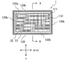
- FIG. 1 shows a configuration example of the partition member of the present invention.
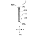
- FIG. 2 is a cross-sectional view of the partition member shown in FIG. 1 cut along the line AA.
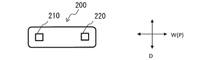
- FIG. 3 shows an example of a single cell.
- FIG. 4 is a front view of the unit cell shown in FIG.
- FIG. 5 is a side view of the unit cell shown in FIG.
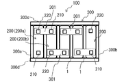
- FIG. 6 is a top view showing an example of a battery pack.
- FIG. 7 is a side view schematically showing the side surface of the battery pack shown in FIG. 6 with the side plate on the front side removed.
- the partitioning member of the present invention is a partitioning member for partitioning between single cells or between single cells and members other than single cells, and contains a powdered inorganic substance and a fibrous inorganic substance, and its density is 0.23 to 1.10 g / cm. It is characterized by including a heat insulating material which is 3 . Moreover, it is preferable that this heat insulating material is a porous body and can hold a liquid. Furthermore, the partition member may be made of only the heat insulating material as long as it includes the heat insulating material having the above features, but in the preferred embodiment, the heat insulating material is accommodated in the outer package. It is a thing.
- the partition member includes the above-described heat insulating material, it is possible to prevent the heat insulating material from significantly reducing or losing the heat resistance and the heat insulating property due to the pressure applied to the partition member. That is, when the heat insulating material of the partition member which receives the heat from the secondary battery maintains the desired heat resistance and heat insulating property, it is possible to block the heat transfer to another secondary battery or the like.
- FIG. 1 shows a configuration example of the partition member of the present invention.
- a front view of the partition member 1 is shown in FIG.
- FIG. 2 shows a cross section on the right side in the case where the partition member shown in FIG. 1 is cut along the line AA.
- the partition member 1 has a flat or sheet-like overall shape having a height direction (H), a width direction (W) and a thickness direction (D).
- the partition member 1 has a thickness direction (D) and a surface direction (P) orthogonal to the thickness direction (D).
- the plane direction (P) includes the height direction (H) and the width direction (D) described above, and a plurality of oblique directions between the height direction (H) and the width direction (D).
- the partition member 1 is used in the thickness direction (D) to partition between the unit cells constituting the assembled battery, or to divide the unit cell and a member other than the unit cell.
- the partition member 1 includes a heat insulating material 110, and preferably includes an exterior body 120 that houses the heat insulating material 110 capable of holding a liquid.
- the heat insulating material 110 includes a powdered inorganic substance and a fibrous inorganic substance.
- fibrous inorganic substance means an inorganic substance having a shape with a major axis of 100 times or more of the minor axis
- “powdered inorganic substance” means an inorganic substance with a major axis less than 100 times the minor axis.
- long diameter means fiber length
- short diameter means the diameter of a cross section orthogonal to the long diameter direction.
- the heat insulating material used for the partition member is made of only a powdery inorganic substance, the formability of the heat insulating material is poor and the shape is difficult to maintain, and therefore, it is necessary to use a binder or the like for hardening. When such a partition member is placed under pressure and compressed, it becomes difficult to maintain its shape, and the heat resistance is deteriorated.
- the heat insulating material used for the partition member is made of only fibrous inorganic material, the heat insulating property tends to increase due to the air layer in the gaps of the fibers constituting the heat insulating material, but under high temperature Heat insulation will be reduced.
- the partition member is placed under pressure and compressed, there is a problem that the partition member is easily deformed.
- the heat insulating material used for the partition member of the present invention solves the above-mentioned point by using a powdery inorganic material and a fibrous inorganic material in combination.
- the fibrous inorganic substance is, for example, at least one selected from the group consisting of paper, cotton sheet, polyimide fiber, aramid fiber, polytetrafluoroethylene (PTFE) fiber, glass fiber, rock wool, ceramic fiber and biosoluble inorganic fiber Among these, at least one selected from glass fiber, rock wool, ceramic fiber and biosoluble inorganic fiber is particularly preferable.
- the powdered inorganic substance is preferably at least one selected from the group consisting of silica particles, alumina particles, calcium silicate, clay minerals, vermiculite, mica, cement, perlite, fumed silica and airgel, for example.
- silica particles, alumina particles, calcium silicate and vermiculite is particularly preferable.
- types of calcium silicate, Zonotrite, Tobermorite, Wollastonite, and Gyrolight are preferable, and Gyrolight is particularly preferable.
- Gyrolight having a petal-like structure maintains a porous structure even when it is compressed and deformed, so it is excellent in liquid retention.
- the clay minerals are mainly magnesium silicate (including talc and sepiolite), montmorillonite and kaolinite.
- thermoelectric material As a heat insulating material containing a fibrous inorganic substance and a powdered inorganic substance, it is possible to select and use one of known ones that satisfies a predetermined density. For example, those selected from those described in JP-A 2003-202099 can be used.
- the heat insulating material has a density of 0.23 to 1.10 g / cm 3 in order to be lightweight and to maintain heat insulation even at high temperatures.
- the density of the heat insulating material is more than the above lower limit value, it is preferable from the viewpoints of heat insulation and liquid retention since there are many air layers in the internal void, while on the other hand, the deformation amount at compression is less than the above upper limit value Is preferable from the viewpoint that Further, from these viewpoints, the density of the heat insulating material is preferably 0.35 g / cm 3 or more, more preferably 0.55 g / cm 3 or more, and preferably 1.05 g / cm 3 or less. And more preferably 1.00 g / cm 3 or less.
- the whole of the heat insulating material 110 is formed with a porous body.
- the entire heat insulating material 110 is formed of a porous body, and the liquid is held in the cavity of the porous body.
- the heat insulating material 110 preferably has elasticity so as to correspond to pressure. However, it may not have elasticity.
- the liquid to be used is preferably a liquid having a boiling point of 80 ° C. to 250 ° C. at normal pressure, and more preferably a liquid having a boiling point of 100 ° C. to 150 ° C. at normal pressure.
- Specific examples of the liquid to be used include, besides water, at least one selected from the group consisting of alcohols, esters, ethers, ketones, hydrocarbons, fluorine compounds and silicone oils, for example. preferable. These can be used alone or as a mixture of two or more.
- the liquid may contain additives such as antifreeze imparting substances (antifreeze agents), preservatives, pH adjusters and the like.
- the provision of the antifreeze property can prevent breakage of the outer package due to expansion due to freezing.
- the pH of the liquid is changed by the addition of the pH adjusting agent depending on the components eluted from the powdered inorganic substance, and the possibility of deterioration of the powdered inorganic substance, the package, and the liquid (water) itself can be reduced. What is included in water is not limited to this, and can be added as needed.
- the exterior body 120 encloses the liquid and the heat insulating material 110 in a sealed state.
- a resin or metal film or sheet can be applied.
- the metal examples include aluminum foil, copper foil, tin foil, nickel foil, stainless steel foil, lead foil, tin-lead alloy foil, blue copper foil, silver foil, iridium foil and phosphor blue copper foil.
- aluminum foil, copper foil and nickel foil are preferable, and aluminum foil is more preferable.
- the metal is preferably at least one selected from the examples listed above.
- thermosetting resin at least one of a thermosetting resin and a thermoplastic resin
- a thermoplastic resin it is preferable to use a thermoplastic resin.
- the resin include polyethylene, polypropylene, polystyrene, nylon, acrylic, epoxy resin, polyurethane, polyetheretherketone, polyethylene terephthalate, polyphenylene sulfide, polycarbonate, aramid and the like.
- at least one selected from polypropylene, nylon and polyethylene terephthalate is preferable.
- the thickness of the exterior body 120 is not particularly limited, and is, for example, 5 ⁇ m to 200 ⁇ m.
- the metal foil can be 3 ⁇ m to 50 ⁇ m, and the resin layer can be 2 ⁇ m to 150 ⁇ m. Thereby, the heat resistance and the low water vapor permeability of the metal foil can be exhibited, and the sealing property can be improved by the resin.
- the heat insulating material 110 is sealed (sealed) in the outer package 120 by bonding the peripheral portions of the two outer packages in an annular shape by heat fusion, adhesion, or the like.
- one outer package may be bent and the peripheral portions thereof may be joined by heat fusion, adhesion or the like to seal (seal) the liquid and the heat insulating material 110.
- the exterior body 120 preferably has flexibility (elasticity), but may not have flexibility.
- the case 120 is provided with a sealing portion 120 a for sealing the peripheral portion thereof, and the heat insulating material 110 is an internal space 111 formed in the case 120 by sealing with the sealing portion 120 a.
- a gap 120 b is provided between the sealing portion 120 a and the heat insulating material 110.
- region S2 region S2.
- the gap 120 b is not necessarily required.
- the gap 120 b may be in a state in which the inner surfaces of the exterior body 120 are in contact with each other when there is no fluid (gas and liquid).
- the volume of the internal space 111 is defined as the product of the area of the internal space 111 and the thickness of the heat insulating material 110.
- the arrangement of the heat insulating material does not necessarily have to be at the center of the inner space and is not necessarily parallel to the outer package.
- the assembled battery includes, for example, electric vehicles (EVs), hybrid electric vehicles (Hybrid Electric Vehicles (HEVs), plug-in hybrid electric vehicles (PHEVs), electric heavy motors, electric motorcycles, electric assists. Bicycles, ships, aircraft, trains, Uninterruptible Power Supply (UPS), household storage systems, storage battery systems for power system stabilization using renewable energy such as wind power / solar power / tidal power / geothermal power, etc. Applied to the battery pack mounted on the. However, the battery pack can also be used as a power source for supplying power to devices other than the above-described EV and the like.
- EVs electric vehicles
- HEVs Hybrid Electric Vehicles
- PHEVs plug-in hybrid electric vehicles
- Electric heavy motors electric motorcycles
- Electric assists Bicycles, ships, aircraft, trains, Uninterruptible Power Supply (UPS), household storage systems, storage battery systems for power system stabilization using renewable energy such as wind power / solar power / tidal power / geother
- FIG. 3 is a plan view showing an example of a unit cell constituting the assembled battery
- FIG. 4 is a front view of the unit cell shown in FIG. 3
- FIG. 5 is a right side view of the unit cell.
- the unit cell 200 is formed in a rectangular shape having a height direction (H), a width direction (W), and a thickness direction (D), and the terminals 210 and 220 are provided on the top surface thereof.
- the unit cell 200 is, for example, a lithium ion secondary battery including a positive electrode and a negative electrode capable of inserting and extracting lithium ions, and an electrolyte.
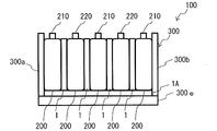
- secondary batteries such as lithium ion all solid batteries, nickel hydrogen batteries, nickel cadmium batteries, lead storage batteries and the like can be applied.
- FIG. 6 shows a top view of a battery assembly 100 formed using a plurality of unit cells 200
- FIG. 7 is a side view schematically showing a state in which the side plate 300d is removed from the battery assembly 100 shown in FIG.
- the battery assembly 100 includes a housing 300 and a plurality of single cells 200 housed in the housing 300.
- the housing 300 includes a bottom plate 300e and side plates 300a, 300b, 300c, and 300d erected along the outer periphery of the bottom plate 300e.
- FIG. 6 and FIG. 7 illustrate five single cells 200 as an example, the number of single cells can be appropriately selected.
- the plurality of unit cells 200 are arranged in the thickness direction, and the partition member 1 described above is arranged between the unit cells 200.
- the battery pack 100 is electrically connected in series by the bus bar 301 with the positive electrode terminal (e.g., the terminal 210) and the negative electrode terminal (e.g., the terminal 220) of the adjacent (opposing) single cells 200 via the partition member 1.
- the partition member 1 ⁇ / b> A is disposed between the upper surface of the bottom plate 300 e of the housing 300 and each of the single cells 200.
- the partition member 1A has the same configuration as the partition member 1.
- Heat generation and heat transfer in a battery pack A part or all of the electrodes constituting the unit cell 200 or the chemical substances constituting the electrolytic solution cause a decomposition reaction while generating heat in the unit cell 200, whereby the temperature of the unit cell 200 rises, and the unit cell Some or all of the region 200 may reach 200 ° C. or higher. In the present invention, this state is called "abnormal heating state".
- the stability of the crystal structure after lithium removal by charging is greatly influenced by the safety of the positive electrode material among the materials constituting the unit cell 200.
- Materials such as LiCoO 2 , Li (Ni 1/3 Mn 1/3 Co 1/3 ) O 2 , Li (Ni 0.8 Co 0.15 Al 0.05 ) O 2 generally used as positive electrode materials are charged. In the state, under high temperature, crystal collapse accompanied by oxygen release occurs. Oxygen released from the positive electrode causes oxidation or the like of the electrolytic solution, resulting in a rapid exothermic reaction. Structural analysis using synchrotron radiation has reported that crystal phase transition occurs at around 200 ° C. in the above-mentioned positive electrode material species.
- the chargeable negative electrode (lithium insertion carbon negative electrode) basically exhibits the same strong reducibility as lithium metal, and on the negative electrode surface by the reaction with the electrolyte. It is known that a film is formed on the surface, which suppresses the further reaction. Therefore, the chemical composition, structure, and thermal stability of the protective film greatly affect the thermal stability of the chargeable negative electrode when the temperature rises.
- the reaction between the charged negative electrode and the electrolyte is explained by the formation of a protective film and the subsequent explosive reductive decomposition reaction by film destruction.
- a state in which a chemical substance constituting an electrode constituting a single cell 200, an electrolytic solution or the like does not cause a decomposition reaction with a predetermined heat generation rate or more in the single cell 200 is referred to as a "normal state".
- the heat generation state of the unit cell 200 is evaluated using ARC (Accelerating rate calorie) which is a means for quantitatively measuring the thermal behavior when the reactive chemical substance self-decomposes under adiabatic conditions.
- ARC Accelelerating rate calorie
- the unit cells 200 in the normal state are "unit cells holding the normal state", and the unit cells 200 deviate from the normal state and have not reached the abnormal heat generation state. " The heat generation inside the unit cell 200 is transferred to the other unit cells 200 via various transfer paths. For example, the heat generation inside the single battery 200 can be transmitted to another single battery 200 via the partition member 1.
- the upper limit value of the surface average temperature assumed when the unit cell 200 in contact with or close to the partition member 1 deviates from the normal state and does not reach the abnormal heat generation state is 180 ° C.
- the general-purpose separator material is made of polyethylene or polypropylene, its meltdown temperature is known to be 160 to 200 ° C. For this reason, when the surface average temperature of the unit cell 200 exceeds 180 ° C., a part of the general-purpose separator material constituting the unit cell 200 may melt down, leading to an abnormal heat generation state.
- the partition member 1 is a unit cell in the battery assembly 100.
- a member which transmits heat from the cell 200 (for example, the cell 200a) in its thickness direction and faces the cell 200a via the partition member 1 and the other cell 200 (cell 200b) or the cell 200 300e) can be transmitted.
- the heat causes the liquid contained in the opening of the partition member 1 to flow out in the gas phase state or the liquid phase state.
- Air (having a heat insulating effect) enters the heat insulating material 110 in the partition member 1 by the outflow, and the heat insulating property (heat resistance) in the thickness direction is increased. By this, it is possible to prevent another single battery 200 from being out of the normal state when one single battery 200 becomes out of the normal state.
- the upper limit value of the surface average temperature assumed when the single battery 200 in contact with or in proximity to the partition member 1 does not deviate from the normal state is usually 80.degree.
- the boiling point of the general-purpose electrolyte solution component is 90 ° C. or more as shown in Table 1 below.
- General-purpose electrolyte solution components are, for example, ethylene carbonate (EC), diethyl carbonate, dimethyl carbonate (DMC), ethyl methyl carbonate (EMC).
- EC ethylene carbonate
- DMC dimethyl carbonate
- EMC ethyl methyl carbonate
- the heat transfer in the thickness direction is promoted by the contained liquid.
- the heat transfer resistance of the partition member 1 is lower than that of the conventional product, so that the temperature equalization between the cells 200 in the battery assembly 100 is successful. The effect of reducing the deterioration of the single battery 200 due to unevenness can be expected.
- Example 1 Vermiculite paper (height 50 mm, width 50 mm, thickness 2 mm, density 0.85 g / cm 3 , porous material containing vermiculite (powdery inorganic material) and glass fiber (fibrous inorganic material) was prepared as the heat insulating material 110 .
- the heater temperature was raised to 80 ° C., and when the heater temperature reached 80 ° C., heating at that temperature was continued for 30 minutes.
- the thickness (referred to as "film thickness") of the heat insulating material (partition member) was measured, and the film thickness at compression was determined to be 1.8 mm.
- the room temperature thermal conductivity k L of the heat insulating material was determined from the temperature at each position at the end of heating, the heat conduction resistance from the heater to the heat insulating material, and the thickness of the heat insulating material when compressed according to the following equation.
- k L ( ⁇ T1 ⁇ L) / ( ⁇ T2 ⁇ R) k L : Thermal conductivity of heat insulating material [W / (m ⁇ K)]
- ⁇ T1 temperature difference [K] between the high temperature side surface and the low temperature side surface of the heat insulating plate
- L Film thickness at the time of compression of the heat insulating material [m]
- R Heat conduction resistance from the heater to the heat insulating material 6.8 ⁇ 10 -3 [m 2 ⁇ K / W]
- the thermal conductivity k L was 0.08 W / (m ⁇ K) 30 minutes after the heater reached 80 ° C.
- the temperature of the heater was raised to 600 ° C., and after the temperature of the heater reached 600 ° C., heating at that temperature was continued for 1 hour.
- the film thickness of the heat insulating material (partition member) was measured, and the film thickness at compression was determined to be 1.9 mm. From the temperature at each position at the end of heating, the heat conduction resistance from the heater to the heat insulating material, and the film thickness at the time of compression of the heat insulating material, the thermal conductivity k H of the heat insulating material was determined according to the following equation.
- k H ( ⁇ T 3 / R ⁇ q) ⁇ L / ⁇ T 4 (Expression)
- k H Thermal conductivity of thermal insulation material [W / (m ⁇ K)]
- ⁇ T3 temperature difference [K] between the high temperature side surface and the low temperature side surface of the heat insulating plate
- a ⁇ T4 Temperature difference [K] between the high temperature side and the low temperature side of the heat insulating material
- L Thickness (film thickness) at the time of compression of the heat insulating material [m]
- R Heat conduction resistance from the heater to the heat insulating material 1.65 ⁇ 10 -4 [m 2 ⁇ K / W]
- q Heat loss due to convection and radiation from each brass plate and heat insulating material 1.35 ⁇ 10 4 [W / m 2 ]
- the surface on the high temperature side and the surface on the low temperature side in the above equation indicate the surface near the heater and the opposite surface, respectively.
- the thermal conductivity k H after one hour after the heater reached 600 ° C. was 0.08 W / (m ⁇ K).
- Example 2 Using a heat insulating sheet (density 0.95 g / cm 3 , porous body containing wollastonite (powdery inorganic substance) and rock wool (fibrous inorganic substance)) having a thickness of 2 mm instead of the vermiculite paper in Example 1 The same experiment as in Example 1 was performed.
- the film thickness at the time of compression in normal temperature thermal conductivity measurement was 1.8 mm
- the film thickness at the time of compression in high temperature thermal conductivity measurement was 1.9 mm.
- Example 3 Instead of vermiculite paper in Example 1, calcium silicate paper (density 0.38 g / cm 3 , porous body containing calcium silicate (powdery inorganic substance) and rock wool (fibrous inorganic substance)) having a thickness of 1 mm 2
- Example 3 the film thickness at compression in normal temperature thermal conductivity measurement was 1.9 mm, and the film thickness at compression in high temperature thermal conductivity measurement was 1.7 mm.
- Example 4 Example 1 using a stack of two sheets of calcium silicate paper (density 0.25 g / cm 3 , a porous body containing calcium silicate and rock wool) having a thickness of 1 mm instead of the vermiculite paper in Example 1. The same experiment was performed.
- the film thickness at the time of compression in normal temperature thermal conductivity measurement was 1.7 mm
- the film thickness at the time of compression in high temperature thermal conductivity measurement was 1.6 mm.
- Example 1 The same experiment as in Example 1 except that four sheets of glass fiber paper (porous body with a density of 0.22 g / cm 3 ) containing 0.6 mm thick vermiculite were used instead of the vermiculite paper in Example 1 Did.
- the film thickness at the time of compression in normal temperature thermal conductivity measurement was 1.4 mm
- the film thickness at the time of compression in high temperature thermal conductivity measurement was 1.6 mm.
- Example 2 The same experiment as in Example 1 using a stack of three sheets of rock wool paper (porous body with a density of 1.16 g / cm 3 ) containing vermiculite having a thickness of 0.9 mm instead of the vermiculite paper in Example 1 Did.
- the film thickness at the time of compression in normal temperature thermal conductivity measurement was 2.0 mm
- the film thickness at the time of compression in high temperature thermal conductivity measurement was 2.0 mm.
- Example 3 The same experiment as in Example 1 was performed using a stack of four glass fiber papers (porous bodies with a density of 0.125 g / cm 3 ) having a thickness of 0.6 mm instead of the vermiculite paper in Example 1.
- the film thickness at the time of compression in normal temperature thermal conductivity measurement was 1.4 mm
- the film thickness at the time of compression in high temperature thermal conductivity measurement was 1.4 mm.
- Example 4 In place of the vermiculite paper in Example 1, vermiculite powder (containing no fibrous inorganic substance) was used. The vermiculite powder alone has poor formability and is likely to lose its shape, so an aluminum laminate film (including polyethylene (inner), aluminum, polyethylene terephthalate (outer) including 0.15 mm thick) containing vermiculite powder (thickness 2 mm) The same experiment as in Example 1 was performed using a density of 0.6 g / cm 3 ). In the comparative example 4, the film thickness at the time of compression in normal temperature thermal conductivity measurement was 1.7 mm, and the film thickness at the time of compression in high temperature thermal conductivity measurement was 1.8 mm.
- Example 5 The same experiment as in Example 1 was performed using a 1.8 mm thick vermiculite paper (density 1.56 g / cm 3 , a porous body containing vermiculite and glass fibers) instead of the vermiculite paper in Example 1.
- the film thickness at the time of compression in normal temperature thermal conductivity measurement was 1.8 mm
- the film thickness at the time of compression in high temperature thermal conductivity measurement was 1.8 mm.
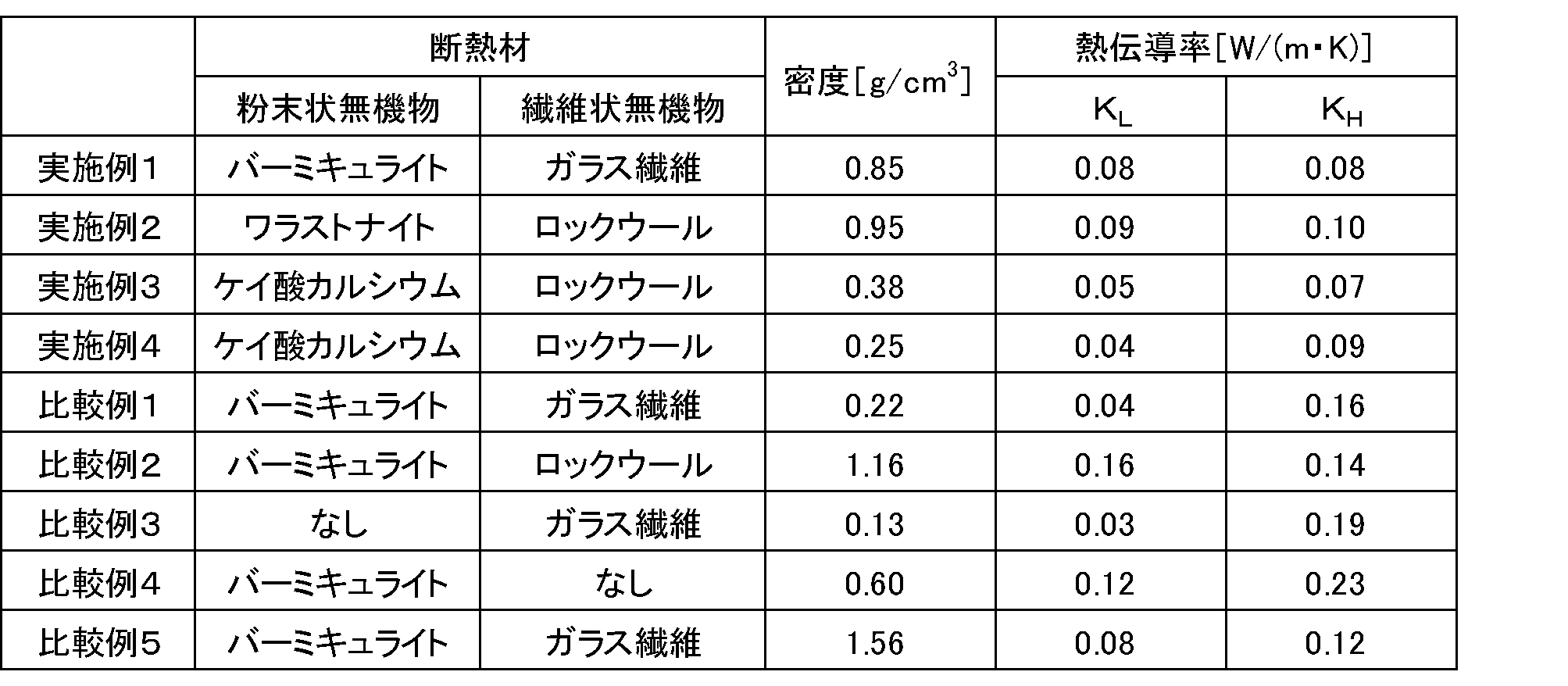
- Table 2 shows the relationship between the thermal conductivity and the density of the heat insulating material used in each of the partition members obtained by the experiments according to Examples 1 to 4 and Comparative Examples 1 to 5 described above. From the experimental results, the partition member of the present invention which is used in combination with the powdery inorganic substance and the fibrous inorganic substance has a high temperature thermal conductivity lower than that of Comparative Example 3 and Comparative Example 4 and has better thermal insulation at high temperatures. I understand that.
- the partition member according to the present invention is a comparative example 1 using a heat insulating material having a density of 0.22 g / cm 3 as a partition member, and a heat insulator having a density of 1.16 g / cm 3 It can be seen that the thermal conductivity is particularly low at high temperature and shows better thermal insulation at high temperatures than each of Comparative Example 2 used as a member and Comparative Example 5 used a partition member with a heat insulating material having a density of 1.56 cm 3. .
Landscapes
- Chemical & Material Sciences (AREA)
- Chemical Kinetics & Catalysis (AREA)
- Electrochemistry (AREA)
- General Chemical & Material Sciences (AREA)
- Engineering & Computer Science (AREA)
- Manufacturing & Machinery (AREA)
- Ceramic Engineering (AREA)
- Materials Engineering (AREA)
- Structural Engineering (AREA)
- Organic Chemistry (AREA)
- Secondary Cells (AREA)
- Battery Mounting, Suspending (AREA)
Abstract
Description
[2]前記断熱材が多孔質体である、[1]に記載の仕切り部材。
[3]前記粉末状無機物がシリカ粒子、アルミナ粒子、ケイ酸カルシウム及びバーミキュライトから選ばれる少なくとも一つである、[1]又は[2]に記載の仕切り部材。
[4]前記繊維状無機物がガラス繊維、ロックウール、セラミック繊維及び生体溶解性無機繊維から選ばれる少なくとも一つである、[1]乃至[3]のいずれか一つに記載の仕切り部材。
本発明の仕切り部材は、単電池間又は単電池と単電池以外の部材とを仕切る仕切り部材であって、粉末状無機物及び繊維状無機物を含み、その密度が0.23~1.10g/cm3である断熱材を含むことを特徴とする。また、この断熱材は多孔質体であり、液体を保持可能なものであることが好ましい。更に、この仕切り部材は上記の特徴を有する断熱材を含むものであれば、断熱材のみからなるものであっても構わないが、その好ましい実施形態は、断熱材が外装体に収容されているものである。
断熱材110は、粉末状無機物及び繊維状無機物を含む。本発明において、「繊維状無機物」は長径が短径の100倍以上の形状を有する無機物を意味し、「粉末状無機物」は長径が短径の100倍未満の形状を有する無機物を意味する。なお、特に繊維状である場合には「長径」は繊維長を意味し、「短径」は長径方向に対して直行する断面の径を意味する。
多孔質体に液体を保持させる場合、用いる液体としては、常圧における沸点が80℃以上250℃以下の液体が好ましく、常圧における沸点が100℃以上150℃以下の液体がさらに好ましい。用いる液体の具体例としては、水の他、例えば、アルコール類、エステル類、エーテル類、ケトン類、炭化水素類、フッ素系化合物及びシリコーン系オイルからなる群から選ばれる少なくとも一つを含むことが好ましい。これらは一種のみでも、二種以上の混合物として用いることもできる。液体は、不凍性を付与する物質(不凍剤)、防腐剤、pH調整剤などの添加物を含んでもよい。不凍性の付与により、凍結に伴う膨張により外装体が破損するのを回避し得る。また、pH調整剤の添加によって、粉末状無機物から溶出する成分等によって液体のpHが変化し、粉末状無機物、外装体、液体(水)自体が変質する可能性を低減できる。水に含めるものはこれに限られず、必要に応じて追加することができる。
外装体120は、液体及び断熱材110を密封状態で収容する。外装体120としては、例えば、樹脂や金属製のフィルムやシートを適用することができる。例えば、金属と樹脂とを積層したフィルムやシートを用いて液体を保持した断熱材をラミネートするのが高い耐熱性及び強度を得る上で好ましい。上記ラミネートに用いる、金属と樹脂との積層構造を有するラミネート体として、樹脂層、金属層、樹脂シーラント層を含む3層以上のラミネート体を適用するのが好ましい。金属は、例えば、アルミニウム箔、銅箔、錫箔、ニッケル箔、ステンレス箔、鉛箔、錫鉛合金箔、青銅箔、銀箔、イリジウム箔及び燐青銅箔などである。特に、アルミニウム箔、銅箔、ニッケル箔であるのが好ましく、アルミニウム箔であるのがさらに好ましい。金属は、上記列記した例示から少なくとも一つ選択されるのが好ましい。
次に、仕切り部材1が適用される組電池について説明する。組電池は、例えば、電気自動車(Electric Vehicle: EV)、ハイブリッド電気自動車(Hybrid Electric Vehicle: HEV)、プラグインハイブリッド電気自動車(Plug-in Hybrid Electric Vehicle: PHEV)、電動重機、電動バイク、電動アシスト自転車、船舶、航空機、電車、無停電電源装置(Uninterruptible Power Supply: UPS)、家庭用蓄電システム、風力/太陽光/潮力/地熱等の再生可能エネルギーを利用した電力系統安定化用蓄電池システム等に搭載される電池パックに適用される。但し、組電池は、上述のEV等以外の機器に電力を供給する電力源としても使用し得る。
図3は組電池を構成する単電池の一例を示す平面図であり、図4は図3に示した単電池の正面図であり、図5は、単電池の右側面図である。単電池200は、高さ方向(H)、幅方向(W)、厚み方向(D)を有する直方体状に形成されており、その上面に端子210、端子220が設けられている。単電池200は、例えば、リチウムイオンを吸蔵・放出可能な正極及び負極、並びに電解質を備えるリチウムイオン二次電池である。リチウムイオン二次電池以外に、リチウムイオン全固体電池、ニッケル水素電池、ニッケルカドミウム電池、鉛蓄電池等の二次電池を適用し得る。
図6は、複数の単電池200を用いて形成された組電池100の上面図を示し、図7は、図6に示した組電池100から側板300dを取り外した状態を模式的に示す側面図である。図6及び図7において、組電池100は、筐体300と筐体300内に収容された複数の単電池200とを含む。筐体300は、底板300eと、底板300eの外周に沿って立設された側板300a、300b、300c及び300dとを有する。図6及び図7では、一例として5個の単電池200が例示されているが、単電池の数は適宜選択可能である。
単電池200を構成する電極や電解液等を構成する化学物質の一部ないし全てが、単電池200内部で発熱を伴いながら分解反応を起こすことにより、単電池200の温度が上昇し、単電池200の一部ないし全領域が200℃以上になる場合がある。本発明において、この状態を「異常発熱状態」という。

(実施例1)
断熱材110として、バーミキュライト紙(高さ50mm、幅50mm、厚さ2mm、密度0.85g/cm3、バーミキュライト(粉末状無機物)とガラス繊維(繊維状無機物)を含む多孔質体)を用意した。
上記した断熱材を用いて、ヒーター、真鍮板、断熱板A(ミスミ社、型式:HIPHA、厚さ10mm)、真鍮板、多孔質体、真鍮板、断熱板A、真鍮板、断熱板B(ミスミ社、型式:HIPHA、厚さ40mm)の順番ではさんで各部材を密着させ、前述の断熱材を仕切り部材として用いた。断熱板Bの上側から油圧プレス機HYP505H(日本オートマチックマシン社製)を用いて荷重が375kgとなるように調整した(15kgf/cm2に相当する)。
kL= (ΔT1×L)/(ΔT2×R)
kL:断熱材の熱伝導率[W/(m・K)]
ΔT1:断熱板Aの高温側の面と低温側の面の温度差[K]
ΔT2:断熱材高温側の面と低温側の面の温度差[K]
L:断熱材の圧縮時の膜厚[m]
R:ヒーターから断熱材までの熱伝導抵抗 6.8×10⁻³[m2・K/W]
上記した常温熱伝導率測定に用いたものと同様の断熱材を用いて、下から順に、ヒーター、真鍮板(同じものを2枚重ねて使用)、断熱材、真鍮板、断熱板A、真鍮板、断熱板Bの順番で重ねて各部材を密着させ、前述の断熱材を仕切り部材として用いた。断熱板Bの上側から油圧プレス機を用いて荷重が375kgとなるように調整した(15kgf/cm2に相当する)。
kH=(ΔT3/R-q)×L/ΔT4・・・(式)
kH:断熱材の熱伝導率[W/(m・K)]
ΔT3:断熱板Aの高温側の面と低温側の面の温度差[K]
ΔT4:断熱材の高温側の面と低温側の面の温度差[K]
L:断熱材の圧縮時の厚み(膜厚)[m]
R:ヒーターから断熱材までの熱伝導抵抗 1.65×10⁻⁴[m2・K/W]
q:各真鍮板、断熱材からの対流・放射による熱損失 1.35×10⁴[W/m2 ]
実施例1におけるバーミキュライト紙の代わりに、厚み2mmの断熱シート(密度0.95g/cm3、ワラストナイト(粉末状無機物)とロックウール(繊維状無機物)とを含む多孔質体)を用いて実施例1と同じ実験を行った。実施例2において、常温熱伝導率測定における圧縮時の膜厚は1.8mm、高温熱伝導率測定における圧縮時の膜厚は1.9mmであった。
実施例1におけるバーミキュライト紙の代わりに、厚み1mmのケイ酸カルシウム紙(密度0.38g/cm3、ケイ酸カルシウム(粉末状無機物)とロックウール(繊維状無機物)を含む多孔質体)を2枚重ねたものを用いて実施例1と同じ実験を行った。実施例3において、常温熱伝導率測定における圧縮時の膜厚は1.9mm、高温熱伝導率測定における圧縮時の膜厚は1.7mmであった。
実施例1におけるバーミキュライト紙の代わりに、厚み1mmのケイ酸カルシウム紙(密度0.25g/cm3、ケイ酸カルシウムとロックウールを含む多孔質体)を2枚重ねたものを用いて実施例1と同じ実験を行った。実施例4において、常温熱伝導率測定における圧縮時の膜厚は1.7mm、高温熱伝導率測定における圧縮時の膜厚は1.6mmであった。
実施例1におけるバーミキュライト紙の代わりに、厚み0.6mmのバーミキュライトを含んだガラス繊維紙(密度0.22g/cm3の多孔質体)を4枚重ねたものを用いて実施例1と同じ実験を行った。比較例1において、常温熱伝導率測定における圧縮時の膜厚は1.4mm、高温熱伝導率測定における圧縮時の膜厚は1.6mmであった。
実施例1におけるバーミキュライト紙の代わりに、厚み0.9mmのバーミキュライトを含んだロックウール紙(密度1.16g/cm3の多孔質体)を3枚重ねたものを用いて実施例1と同じ実験を行った。比較例2において、常温熱伝導率測定における圧縮時の膜厚は2.0mm、高温熱伝導率測定における圧縮時の膜厚は2.0mmであった。
実施例1におけるバーミキュライト紙の代わりに、厚み0.6mmのガラス繊維紙(密度0.125g/cm3の多孔質体)を4枚重ねたものを用いて実施例1と同じ実験を行った。比較例3において、常温熱伝導率測定における圧縮時の膜厚は1.4mm、高温熱伝導率測定における圧縮時の膜厚は1.4mmであった。
実施例1におけるバーミキュライト紙の代わりに、バーミキュライト粉末(繊維状無機物を含まないもの)を用いた。バーミキュライト粉末単体では成形性が悪く形状が崩れやすいためアルミラミネートフィルム(ポリエチレン(内側)、アルミニウム、ポリエチレンテレフタレート(外側)を含む。厚み0.15mm)内にバーミキュライト粉末を内包させたもの(厚み2mm、密度0.6g/cm3)を用いて実施例1と同じ実験を行った。比較例4において、常温熱伝導率測定における圧縮時の膜厚は1.7mm、高温熱伝導率測定における圧縮時の膜厚は1.8mmであった。
実施例1におけるバーミキュライト紙の代わりに、厚み1.8mmのバーミキュライト紙(密度1.56g/cm3、バーミキュライトとガラス繊維を含む多孔質体)を用いて実施例1と同じ実験を行った。比較例5において、常温熱伝導率測定における圧縮時の膜厚は1.8mm、高温熱伝導率測定における圧縮時の膜厚は1.8mmであった。
100 組電池
110 断熱材
120 外装体
200 単電池
300 筐体
Claims (5)
- 単電池間又は単電池と単電池以外の部材とを仕切る仕切り部材であって、
粉末状無機物及び繊維状無機物を含み、その密度が0.23~1.10g/cm3である断熱材を含む仕切り部材。 - 前記断熱材が多孔質体である、請求項1に記載の仕切り部材。
- 前記粉末状無機物がシリカ粒子、アルミナ粒子、ケイ酸カルシウム及びバーミキュライトから選ばれる少なくとも一つである、請求項1又は2に記載の仕切り部材。
- 前記繊維状無機物がガラス繊維、ロックウール、セラミック繊維及び生体溶解性無機繊維から選ばれる少なくとも一つである、請求項1乃至3のいずれか一項に記載の仕切り部材。
- 複数の単電池と、請求項1乃至4のいずれか一項に記載の仕切り部材とを含む組電池。
Priority Applications (5)
| Application Number | Priority Date | Filing Date | Title |
|---|---|---|---|
| CN201880076401.1A CN111386627B (zh) | 2017-11-30 | 2018-11-30 | 分隔构件和电池组 |
| EP18883501.1A EP3719922B1 (en) | 2017-11-30 | 2018-11-30 | Partition member and assembled battery |
| JP2019556760A JP7354842B2 (ja) | 2017-11-30 | 2018-11-30 | 仕切り部材及び組電池 |
| US16/885,465 US12583799B2 (en) | 2017-11-30 | 2020-05-28 | Partition member and assembled battery |
| JP2023093995A JP7605249B2 (ja) | 2017-11-30 | 2023-06-07 | 仕切り部材及び組電池 |
Applications Claiming Priority (2)
| Application Number | Priority Date | Filing Date | Title |
|---|---|---|---|
| JP2017231170 | 2017-11-30 | ||
| JP2017-231170 | 2017-11-30 |
Related Child Applications (1)
| Application Number | Title | Priority Date | Filing Date |
|---|---|---|---|
| US16/885,465 Continuation US12583799B2 (en) | 2017-11-30 | 2020-05-28 | Partition member and assembled battery |
Publications (1)
| Publication Number | Publication Date |
|---|---|
| WO2019107560A1 true WO2019107560A1 (ja) | 2019-06-06 |
Family
ID=66665637
Family Applications (1)
| Application Number | Title | Priority Date | Filing Date |
|---|---|---|---|
| PCT/JP2018/044271 Ceased WO2019107560A1 (ja) | 2017-11-30 | 2018-11-30 | 仕切り部材及び組電池 |
Country Status (5)
| Country | Link |
|---|---|
| US (1) | US12583799B2 (ja) |
| EP (1) | EP3719922B1 (ja) |
| JP (2) | JP7354842B2 (ja) |
| CN (1) | CN111386627B (ja) |
| WO (1) | WO2019107560A1 (ja) |
Cited By (11)
| Publication number | Priority date | Publication date | Assignee | Title |
|---|---|---|---|---|
| JP2021008089A (ja) * | 2019-07-03 | 2021-01-28 | 三菱製紙株式会社 | 熱暴走抑制耐火シート |
| WO2021181951A1 (ja) * | 2020-03-12 | 2021-09-16 | 住友理工株式会社 | バッテリーパック用断熱材およびバッテリーパック |
| WO2022024078A1 (en) * | 2020-07-30 | 2022-02-03 | 3M Innovative Properties Company | Battery cell thermal runaway barrier |
| US20230070599A1 (en) * | 2020-02-21 | 2023-03-09 | Byd Company Limited | Cell array, battery pack, and vehicle |
| JP2023084120A (ja) * | 2021-12-06 | 2023-06-16 | カール・フロイデンベルク・カーゲー | エネルギ貯蔵器システム |
| WO2024048707A1 (ja) * | 2022-08-31 | 2024-03-07 | 三菱ケミカル株式会社 | 仕切部材と組電池及びその製造方法 |
| JP2024514901A (ja) * | 2021-10-12 | 2024-04-03 | メルセデス・ベンツ グループ アクチェンゲゼルシャフト | バッテリハウジング用の隔壁アセンブリ、バッテリ、及び車両 |
| WO2024143441A1 (ja) | 2022-12-28 | 2024-07-04 | 三菱ケミカル株式会社 | 仕切り部材及び組電池 |
| WO2024203354A1 (ja) * | 2023-03-29 | 2024-10-03 | イビデン株式会社 | カバープロテクタ及びその製造方法、並びに電池モジュール |
| JP2025511625A (ja) * | 2022-11-17 | 2025-04-16 | エルジー エナジー ソリューション リミテッド | モジュール内部の温度安定性が改善された二次電池モジュール |
| WO2026038568A1 (ja) * | 2024-08-14 | 2026-02-19 | 日本碍子株式会社 | 断熱材および断熱材の製造方法 |
Families Citing this family (9)
| Publication number | Priority date | Publication date | Assignee | Title |
|---|---|---|---|---|
| US12300848B2 (en) | 2019-09-05 | 2025-05-13 | Samsung Sdi Co., Ltd. | Energy storage module including extinguisher sheet |
| US12355098B2 (en) | 2019-09-05 | 2025-07-08 | Samsung Sdi Co., Ltd. | Energy storage module |
| US12288895B2 (en) | 2019-09-05 | 2025-04-29 | Samsung Sdi Co., Ltd. | Energy storage module |
| US20220123386A1 (en) * | 2019-09-05 | 2022-04-21 | Samsung Sdi Co., Ltd. | Energy storage module |
| US20230291061A1 (en) * | 2022-03-08 | 2023-09-14 | Cuberg, Inc. | Battery assemblies comprising lithium-metal electrochemical cells and pressure-applying structures |
| US20260085457A1 (en) * | 2022-09-16 | 2026-03-26 | Cabot Corporation | Aerogel composition for thermal insulation |
| US20250038297A1 (en) * | 2023-07-24 | 2025-01-30 | Ford Global Technologies, Llc | Traction battery pack thermal barrier and method of assembling traction battery pack thermal barrier |
| JP7763886B2 (ja) * | 2024-03-25 | 2025-11-04 | 本田技研工業株式会社 | セパレータ部材及び電池パック |
| CN120473608A (zh) * | 2024-09-13 | 2025-08-12 | 比亚迪股份有限公司 | 一种电池组件及用电设备 |
Citations (8)
| Publication number | Priority date | Publication date | Assignee | Title |
|---|---|---|---|---|
| US6146783A (en) | 1997-05-22 | 2000-11-14 | Varta Batterie Aktiengesellschaft | Multi-cell storage battery |
| JP2003202099A (ja) | 1992-01-09 | 2003-07-18 | Ibiden Co Ltd | 断熱材組成物 |
| JP2010097693A (ja) | 2008-10-14 | 2010-04-30 | Toyota Motor Corp | 蓄電装置 |
| JP2011165390A (ja) * | 2010-02-05 | 2011-08-25 | Panasonic Corp | 電池ユニット |
| JP2013131428A (ja) | 2011-12-22 | 2013-07-04 | Panasonic Corp | 冷却部付き電池 |
| JP2014035043A (ja) * | 2012-08-09 | 2014-02-24 | Panasonic Corp | 断熱材 |
| JP2016084836A (ja) * | 2014-10-23 | 2016-05-19 | 日東電工株式会社 | 断熱材およびバッテリーカバー |
| WO2017159527A1 (ja) * | 2016-03-14 | 2017-09-21 | パナソニックIpマネジメント株式会社 | 複合シートおよびこれを用いた電池パック |
Family Cites Families (30)
| Publication number | Priority date | Publication date | Assignee | Title |
|---|---|---|---|---|
| FR2752088B1 (fr) * | 1996-08-05 | 1998-09-04 | Accumulateurs Fixes | Batterie monobloc etanche |
| JP2001220258A (ja) * | 2000-02-09 | 2001-08-14 | Toshiba Monofrax Co Ltd | 耐火断熱材 |
| JP4290376B2 (ja) * | 2002-03-20 | 2009-07-01 | ニチアス株式会社 | 防音断熱材およびその製造方法 |
| JP5240963B2 (ja) * | 2003-10-01 | 2013-07-17 | 日産自動車株式会社 | 組電池 |
| US20090053585A1 (en) | 2005-10-03 | 2009-02-26 | Densei-Lambda Kabushiki Kaisha | Battery Pack |
| JP2007134138A (ja) | 2005-11-09 | 2007-05-31 | Nissan Motor Co Ltd | 組電池 |
| US20070292751A1 (en) * | 2006-06-15 | 2007-12-20 | Jing-Yih Cherng | Battery Apparatus with Heat Absorbing Body |
| WO2010032484A1 (ja) | 2008-09-22 | 2010-03-25 | パナソニック株式会社 | 携帯電子機器 |
| KR20110004480A (ko) | 2008-09-22 | 2011-01-13 | 파나소닉 주식회사 | 휴대 전자기기 |
| US8592067B2 (en) * | 2009-06-08 | 2013-11-26 | Panasonic Corporation | Battery pack having a heat insulating layer |
| EP2273162B1 (de) * | 2009-07-06 | 2019-01-09 | Carl Freudenberg KG | Dichtungsrahmen zur Verwendung in einer Batterie |
| US8541126B2 (en) * | 2009-08-31 | 2013-09-24 | Tesla Motors, Inc. | Thermal barrier structure for containing thermal runaway propagation within a battery pack |
| JP2011136859A (ja) * | 2009-12-28 | 2011-07-14 | Asahi Fiber Glass Co Ltd | 繊維系断熱材及びその製造方法 |
| DE102010030881A1 (de) | 2010-07-02 | 2012-01-05 | Robert Bosch Gmbh | Thermische Entkopplung von Batteriezellen im Störfall |
| JP4977253B1 (ja) * | 2011-03-30 | 2012-07-18 | ニチアス株式会社 | 無機繊維質ペーパー及びその製造方法並びに設備 |
| CN103043998B (zh) * | 2011-10-11 | 2016-01-20 | 旭化成化学株式会社 | 绝热材料及其制造方法 |
| JP5271462B1 (ja) * | 2011-10-31 | 2013-08-21 | パナソニック株式会社 | 二次電池ユニット |
| JP5826640B2 (ja) | 2012-01-17 | 2015-12-02 | 日立オートモティブシステムズメジャメント株式会社 | 充電装置 |
| JP2014072055A (ja) | 2012-09-28 | 2014-04-21 | Lithium Energy Japan:Kk | 電池モジュール |
| JP6695800B2 (ja) * | 2013-08-30 | 2020-05-20 | ゴゴロ インク | 熱暴走緩和を伴う携帯式電気エネルギー蓄電装置 |
| JP5905861B2 (ja) * | 2013-09-02 | 2016-04-20 | ニチアス株式会社 | 無機多孔質体を用いた吸熱材 |
| DE102014008000B4 (de) * | 2014-05-26 | 2023-02-02 | K.Tex Knein Technische Textilien Gmbh | Akkumulatorvorrichtung |
| US10603865B2 (en) * | 2014-12-25 | 2020-03-31 | AGC Inc. | Insulating member and its attaching method |
| DE102015007408A1 (de) * | 2015-06-10 | 2016-12-15 | Daimler Ag | Batterie mit wenigstens einem sich unter Wärmeeinwirkung in Dickenrichtung vergrößernden thermischen Isolationselement |
| US10714798B2 (en) * | 2015-09-24 | 2020-07-14 | Autonetworks Technologies, Ltd. | Cooling member and power storage module with same |
| WO2017083743A1 (en) * | 2015-11-13 | 2017-05-18 | Saint-Gobain Ceramics & Plastics, Inc. | Insulation and compression of a high temperature device |
| KR102171649B1 (ko) * | 2015-12-15 | 2020-10-29 | 애플 인크. | 미세다공성 절연체 |
| JP6686828B2 (ja) * | 2016-09-30 | 2020-04-22 | 株式会社オートネットワーク技術研究所 | 蓄電モジュール |
| CN106784518A (zh) | 2017-01-10 | 2017-05-31 | 方乐同 | 一种安全的电池组 |
| EP3598566B1 (en) * | 2017-03-17 | 2024-01-17 | Mitsubishi Chemical Corporation | Partition member and battery pack |
-
2018
- 2018-11-30 CN CN201880076401.1A patent/CN111386627B/zh active Active
- 2018-11-30 WO PCT/JP2018/044271 patent/WO2019107560A1/ja not_active Ceased
- 2018-11-30 EP EP18883501.1A patent/EP3719922B1/en active Active
- 2018-11-30 JP JP2019556760A patent/JP7354842B2/ja active Active
-
2020
- 2020-05-28 US US16/885,465 patent/US12583799B2/en active Active
-
2023
- 2023-06-07 JP JP2023093995A patent/JP7605249B2/ja active Active
Patent Citations (8)
| Publication number | Priority date | Publication date | Assignee | Title |
|---|---|---|---|---|
| JP2003202099A (ja) | 1992-01-09 | 2003-07-18 | Ibiden Co Ltd | 断熱材組成物 |
| US6146783A (en) | 1997-05-22 | 2000-11-14 | Varta Batterie Aktiengesellschaft | Multi-cell storage battery |
| JP2010097693A (ja) | 2008-10-14 | 2010-04-30 | Toyota Motor Corp | 蓄電装置 |
| JP2011165390A (ja) * | 2010-02-05 | 2011-08-25 | Panasonic Corp | 電池ユニット |
| JP2013131428A (ja) | 2011-12-22 | 2013-07-04 | Panasonic Corp | 冷却部付き電池 |
| JP2014035043A (ja) * | 2012-08-09 | 2014-02-24 | Panasonic Corp | 断熱材 |
| JP2016084836A (ja) * | 2014-10-23 | 2016-05-19 | 日東電工株式会社 | 断熱材およびバッテリーカバー |
| WO2017159527A1 (ja) * | 2016-03-14 | 2017-09-21 | パナソニックIpマネジメント株式会社 | 複合シートおよびこれを用いた電池パック |
Non-Patent Citations (4)
| Title |
|---|
| "Battery Handbook", vol. 1, OHMSHA, LTD., article "Denchi Hando Bukku", pages: 591 |
| HIRONORI KOBAYASHI: "Techniques for evaluation and analysis of positive electrode materials for lithium ion secondary batteries using radiant light", 2011, INDUSTRIAL USERS SOCIETY OF SPRING-8, article "Housya-kou wo Mochiita Lithium ion Niji Denchi You Seikyoku Zairyou no Hyouka-Kaiseki Gijutsu" |
| J. DAHN ET AL., ELECTROCHEMISTRY COMMUNICATION, vol. 9, 2007, pages 2534 - 2540 |
| J. DAHN ET AL., ELECTROCHIMICA ACTA, vol. 49, 2004, pages 4599 - 4604 |
Cited By (34)
| Publication number | Priority date | Publication date | Assignee | Title |
|---|---|---|---|---|
| JP2021008089A (ja) * | 2019-07-03 | 2021-01-28 | 三菱製紙株式会社 | 熱暴走抑制耐火シート |
| JP7157013B2 (ja) | 2019-07-03 | 2022-10-19 | 三菱製紙株式会社 | 熱暴走抑制耐火シート |
| JP2023515439A (ja) * | 2020-02-21 | 2023-04-13 | ビーワイディー カンパニー リミテッド | 電池列、電池パック及び車両 |
| JP7492594B2 (ja) | 2020-02-21 | 2024-05-29 | ビーワイディー カンパニー リミテッド | 電池列、電池パック及び車両 |
| US20230070599A1 (en) * | 2020-02-21 | 2023-03-09 | Byd Company Limited | Cell array, battery pack, and vehicle |
| WO2021181951A1 (ja) * | 2020-03-12 | 2021-09-16 | 住友理工株式会社 | バッテリーパック用断熱材およびバッテリーパック |
| JP2021144879A (ja) * | 2020-03-12 | 2021-09-24 | 住友理工株式会社 | バッテリーパック用断熱材およびバッテリーパック |
| JP7009534B2 (ja) | 2020-03-12 | 2022-01-25 | 住友理工株式会社 | バッテリーパック用断熱材およびバッテリーパック |
| CN114080719B (zh) * | 2020-03-12 | 2023-04-28 | 住友理工株式会社 | 电池组用绝热材料以及电池组 |
| CN114080719A (zh) * | 2020-03-12 | 2022-02-22 | 住友理工株式会社 | 电池组用绝热材料以及电池组 |
| WO2022024085A1 (en) * | 2020-07-30 | 2022-02-03 | 3M Innovative Properties Company | Battery cell thermal runaway barrier |
| WO2022024076A1 (en) * | 2020-07-30 | 2022-02-03 | 3M Innovative Properties Company | Battery cell thermal runaway barrier |
| JP7785062B2 (ja) | 2020-07-30 | 2025-12-12 | スリーエム イノベイティブ プロパティズ カンパニー | 電池セル熱暴走バリア |
| US20230238600A1 (en) * | 2020-07-30 | 2023-07-27 | 3M Innovative Properties Company | Battery cell thermal runaway barrier |
| JP2023535480A (ja) * | 2020-07-30 | 2023-08-17 | スリーエム イノベイティブ プロパティズ カンパニー | 電池セル熱暴走バリア |
| JP2023535481A (ja) * | 2020-07-30 | 2023-08-17 | スリーエム イノベイティブ プロパティズ カンパニー | 電池セル熱暴走バリア |
| JP7837314B2 (ja) | 2020-07-30 | 2026-03-30 | スリーエム イノベイティブ プロパティズ カンパニー | 電池セル熱暴走バリア |
| US12626966B2 (en) * | 2020-07-30 | 2026-05-12 | 3M Innovative Properties Company | Battery cell thermal runaway barrier |
| EP4401200A1 (en) * | 2020-07-30 | 2024-07-17 | 3M Innovative Properties Co. | Battery cell thermal runaway barrier |
| WO2022024078A1 (en) * | 2020-07-30 | 2022-02-03 | 3M Innovative Properties Company | Battery cell thermal runaway barrier |
| EP4386122A3 (en) * | 2020-07-30 | 2024-06-26 | 3M Innovative Properties Co. | Battery cell thermal runaway barrier |
| JP2024514901A (ja) * | 2021-10-12 | 2024-04-03 | メルセデス・ベンツ グループ アクチェンゲゼルシャフト | バッテリハウジング用の隔壁アセンブリ、バッテリ、及び車両 |
| JP7675844B2 (ja) | 2021-10-12 | 2025-05-13 | メルセデス・ベンツ グループ アクチェンゲゼルシャフト | バッテリハウジング用の隔壁アセンブリ、バッテリ、及び車両 |
| JP7560526B2 (ja) | 2021-12-06 | 2024-10-02 | カール・フロイデンベルク・カーゲー | エネルギ貯蔵器システム |
| JP2023084120A (ja) * | 2021-12-06 | 2023-06-16 | カール・フロイデンベルク・カーゲー | エネルギ貯蔵器システム |
| WO2024048707A1 (ja) * | 2022-08-31 | 2024-03-07 | 三菱ケミカル株式会社 | 仕切部材と組電池及びその製造方法 |
| JP7794326B2 (ja) | 2022-08-31 | 2026-01-06 | 三菱ケミカル株式会社 | 仕切部材と組電池及びその製造方法 |
| JPWO2024048707A1 (ja) * | 2022-08-31 | 2024-03-07 | ||
| JP2025511625A (ja) * | 2022-11-17 | 2025-04-16 | エルジー エナジー ソリューション リミテッド | モジュール内部の温度安定性が改善された二次電池モジュール |
| JP7765151B2 (ja) | 2022-11-17 | 2025-11-06 | エルジー エナジー ソリューション リミテッド | モジュール内部の温度安定性が改善された二次電池モジュール |
| EP4645560A1 (en) | 2022-12-28 | 2025-11-05 | Mitsubishi Chemical Corporation | Partition member and battery assembly |
| WO2024143441A1 (ja) | 2022-12-28 | 2024-07-04 | 三菱ケミカル株式会社 | 仕切り部材及び組電池 |
| WO2024203354A1 (ja) * | 2023-03-29 | 2024-10-03 | イビデン株式会社 | カバープロテクタ及びその製造方法、並びに電池モジュール |
| WO2026038568A1 (ja) * | 2024-08-14 | 2026-02-19 | 日本碍子株式会社 | 断熱材および断熱材の製造方法 |
Also Published As
| Publication number | Publication date |
|---|---|
| EP3719922A1 (en) | 2020-10-07 |
| US12583799B2 (en) | 2026-03-24 |
| EP3719922B1 (en) | 2026-04-08 |
| EP3719922A4 (en) | 2020-12-23 |
| CN111386627A (zh) | 2020-07-07 |
| CN111386627B (zh) | 2026-03-17 |
| US20200290933A1 (en) | 2020-09-17 |
| JPWO2019107560A1 (ja) | 2020-12-03 |
| JP2023110064A (ja) | 2023-08-08 |
| JP7605249B2 (ja) | 2024-12-24 |
| JP7354842B2 (ja) | 2023-10-03 |
Similar Documents
| Publication | Publication Date | Title |
|---|---|---|
| JP7605249B2 (ja) | 仕切り部材及び組電池 | |
| JP7200944B2 (ja) | 仕切り部材及び組電池 | |
| JP7043813B2 (ja) | 仕切り部材及び組電池 | |
| US11509015B2 (en) | Energy storage module and energy storage device | |
| EP2442380A1 (en) | Battery pack | |
| JP7009892B2 (ja) | 蓄電モジュール及び蓄電パック | |
| JP7027768B2 (ja) | 蓄電モジュール及び蓄電パック | |
| JP7856009B2 (ja) | 組電池 | |
| JPWO2018124231A1 (ja) | 仕切り部材、組電池及び組電池の熱伝達制御方法 | |
| JP6954213B2 (ja) | 充填部材、組電池及び熱伝達の制御方法 | |
| CN119994353B (zh) | 一种电池装置和用电设备 | |
| JP6950416B2 (ja) | 蓄電モジュール及び蓄電パック | |
| JP7464042B2 (ja) | 仕切り部材及び組電池 | |
| WO2026000435A1 (zh) | 电池和用电装置 | |
| JP6954214B2 (ja) | 充填部材、組電池、及び熱伝達の制御方法 | |
| JP7285878B2 (ja) | 二次電池、電池モジュールおよび二次電池の製造方法 | |
| CN119994352B (zh) | 一种电池装置和用电设备 | |
| CN120049107B (zh) | 一种电池装置和用电设备 | |
| WO2026105880A1 (ja) | スペーサ及び組電池 | |
| WO2014010414A1 (ja) | 電池構造体 |
Legal Events
| Date | Code | Title | Description |
|---|---|---|---|
| 121 | Ep: the epo has been informed by wipo that ep was designated in this application |
Ref document number: 18883501 Country of ref document: EP Kind code of ref document: A1 |
|
| ENP | Entry into the national phase |
Ref document number: 2019556760 Country of ref document: JP Kind code of ref document: A |
|
| NENP | Non-entry into the national phase |
Ref country code: DE |
|
| ENP | Entry into the national phase |
Ref document number: 2018883501 Country of ref document: EP Effective date: 20200630 |
|
| WWG | Wipo information: grant in national office |
Ref document number: 2018883501 Country of ref document: EP |