WO2019110011A1 - 一种资源配置方法和装置 - Google Patents
一种资源配置方法和装置 Download PDFInfo
- Publication number
- WO2019110011A1 WO2019110011A1 PCT/CN2018/119843 CN2018119843W WO2019110011A1 WO 2019110011 A1 WO2019110011 A1 WO 2019110011A1 CN 2018119843 W CN2018119843 W CN 2018119843W WO 2019110011 A1 WO2019110011 A1 WO 2019110011A1
- Authority
- WO
- WIPO (PCT)
- Prior art keywords
- symbols
- backhaul
- information
- transmission
- symbol
- Prior art date
- Legal status (The legal status is an assumption and is not a legal conclusion. Google has not performed a legal analysis and makes no representation as to the accuracy of the status listed.)
- Ceased
Links
Images




Classifications
-
- H—ELECTRICITY
- H04—ELECTRIC COMMUNICATION TECHNIQUE
- H04L—TRANSMISSION OF DIGITAL INFORMATION, e.g. TELEGRAPHIC COMMUNICATION
- H04L5/00—Arrangements affording multiple use of the transmission path
- H04L5/003—Arrangements for allocating sub-channels of the transmission path
- H04L5/0044—Allocation of payload; Allocation of data channels, e.g. PDSCH or PUSCH
-
- H—ELECTRICITY
- H04—ELECTRIC COMMUNICATION TECHNIQUE
- H04B—TRANSMISSION
- H04B7/00—Radio transmission systems, i.e. using radiation field
- H04B7/14—Relay systems
- H04B7/15—Active relay systems
- H04B7/155—Ground-based stations
- H04B7/15528—Control of operation parameters of a relay station to exploit the physical medium
- H04B7/15542—Selecting at relay station its transmit and receive resources
-
- H—ELECTRICITY
- H04—ELECTRIC COMMUNICATION TECHNIQUE
- H04B—TRANSMISSION
- H04B7/00—Radio transmission systems, i.e. using radiation field
- H04B7/14—Relay systems
- H04B7/15—Active relay systems
- H04B7/155—Ground-based stations
-
- H—ELECTRICITY
- H04—ELECTRIC COMMUNICATION TECHNIQUE
- H04W—WIRELESS COMMUNICATION NETWORKS
- H04W56/00—Synchronisation arrangements
- H04W56/001—Synchronization between nodes
Definitions
- the present invention relates to the field of communications technologies, and in particular, to a resource configuration method and apparatus.
- the relay technology in a nutshell, is that when the downlink transmission is performed, the signal that the base station needs to send to the terminal is not directly sent to the UE, but is first sent to a relay node (RN), and then forwarded by the relay node.
- RN relay node
- the relay node needs to add some new connection links.
- the different connection links according to the link service object can be classified into the following three types: an access (AC) link, a direct link, and a backhaul (BH) link.
- the direct link is used for the base station to communicate with nearby terminals
- the access link is used for the relay node to communicate with the terminal served by the relay node
- the backhaul link is used for communication between the relay node and the base station.
- the receiving node receiving data from the base station may be regarded as a BH downlink transmission
- the relay node transmitting data to the base station may be regarded as a BH uplink transmission.
- BH uplink transmission and BH downlink transmission can be collectively referred to as BH transmission.
- the relay node transmitting data to the terminal may be regarded as an AC downlink transmission, and the relay node receiving data from the terminal may be regarded as an AC uplink transmission.
- AC uplink transmission and AC downlink transmission can be collectively referred to as AC transmission.
- the relay node when it is switched from the AC downlink transmission to the BH downlink transmission, it is equivalent to the relay node switching from the transmission data to the reception data. Similarly, when the relay node is switched from the AC uplink transmission to the BH uplink transmission, it is equivalent to the relay node switching from the received data to the transmission data. Therefore, it is necessary to consider how to reserve the time resource for the relay node to perform the switching.
- the embodiment of the present application provides a resource configuration method and apparatus.
- the method and the device can adapt to the situation that the available resources of the backhaul transmission change, and improve the utilization rate of the backhaul transmission resources.
- an embodiment of the present application provides a resource configuration method.
- the method includes: the first device sends a first message to the second device, where the first message carries the information of the available symbols transmitted by the backhaul; the first device receives the second message from the second device, where the second message is used to indicate the first Information about the symbol occupied by the device for backhaul transmission.
- the information of the available symbols includes one or more of the following: the number of available symbols, the number of available symbols, the number of unavailable symbols, the number of unavailable symbols, the propagation delay of the backhaul link, and the transmission and reception switching time of the first device.
- the number of available symbols or the number of unavailable symbols may be determined by a symbol time length, a propagation delay of the backhaul link, and a transmission and reception switching time of the first device.
- the number n of unavailable symbols is n satisfying nT-T p ⁇ T Rx/Tx , and n is smaller than m.
- T represents the length of time of a symbol
- T p represents the propagation delay of the backhaul transmission
- T Rx/Tx represents the transmission and reception switching time of the first device
- m is the total number of symbols of the time slot in which the backhaul transmission is located.
- the number n of unavailable symbols is n satisfying nT ⁇ T Rx/Tx , and n is smaller than m.
- T represents the length of time of one symbol
- T Rx/Tx represents the switching time of the first device
- m is the total number of symbols of the time slot in which the backhaul transmission is located.
- the first device When the first device sends the first message to the second device, it generally carries the minimum number of unavailable symbols or the maximum number of available symbols.
- the second device When transmitting the second message to the first device, the second device may use 1 bit to indicate whether the first device performs backhaul transmission according to the minimum unavailable symbol number or the maximum available symbol number.
- an embodiment of the present application provides a resource configuration method.
- the method includes: receiving, by the second device, a first message from the first device, where the first message carries information of available symbols transmitted by the backhaul; and the second device sends a second message to the first device, where the second message is used to indicate A device performs information on the symbols occupied by the backhaul transmission.
- the information of the available symbols includes one or more of the following: the number of available symbols, the number of available symbols, the number of unavailable symbols, the number of unavailable symbols, the propagation delay of the backhaul link, and the transmission and reception switching time of the first device.
- the embodiment of the present application provides a first device for resource configuration.
- the first device includes: a sending unit, configured to send a first message to the second device, where the first message carries information of available symbols for backhaul transmission; and a receiving unit, configured to receive a second message from the second device, the second The message is used to indicate information of the symbol occupied by the first device for backhaul transmission.
- the information of the available symbols includes one or more of the following: the number of available symbols, the number of available symbols, the number of unavailable symbols, the number of unavailable symbols, the propagation delay of the backhaul link, and the transmission and reception switching time of the first device.
- the embodiment of the present application provides a second device for resource configuration.
- the second device includes: a receiving unit, configured to receive, by the first device, a first message, where the first message carries information of available symbols for backhaul transmission, and a sending unit, configured to send a second message to the first device, where the second device
- the message is used to indicate information about the symbol occupied by the first device for backhaul transmission.
- the information of the available symbols includes one or more of the following: the number of available symbols, the number of available symbols, the number of unavailable symbols, the number of unavailable symbols, the propagation delay of the backhaul link, and the transmission and reception switching time of the first device.
- the number of available symbols or the number of unavailable symbols may be transmitted by the symbol time length, the propagation delay of the backhaul link, and the first device. Switch the time to determine. Specifically, when the frame structure is synchronized between the first device and the second device, the number n of unavailable symbols is n satisfying nT-T p ⁇ T Rx/Tx , and n is smaller than m.
- T represents the length of time of a symbol
- T p represents the propagation delay of the backhaul transmission
- T Rx/Tx represents the transmission and reception switching time of the first device
- m is the total number of symbols of the time slot in which the backhaul transmission is located.
- the number n of unavailable symbols is n satisfying nT ⁇ T Rx/Tx , and n is smaller than m.
- T represents the length of time of one symbol
- T Rx/Tx represents the switching time of the first device
- m is the total number of symbols of the time slot in which the backhaul transmission is located.
- the first device sends the first message to the second device, it generally carries the minimum number of unavailable symbols or the maximum number of available symbols.
- the second device may use 1 bit to indicate whether the first device performs backhaul transmission according to the minimum unavailable symbol number or the maximum available symbol number.
- an embodiment of the present application provides a resource configuration method.
- the method includes: the second device generates a configuration message, where the configuration message carries information about a symbol used by the first device to perform backhaul transmission, and the information of the symbol occupied by the backhaul transmission is transmitted by the second device according to the numerology information and the backhaul. Corresponding relationship between the information of the available symbols and the numerology information of the first device; the second device sends a configuration message to the first device.
- an embodiment of the present application provides a resource configuration method.
- the method includes: receiving, by the first device, the configuration message from the second device, where the configuration message carries information about a symbol used for backhaul transmission by the first device, where the information of the occupied symbol for the backhaul transmission is the second device according to the numerology Corresponding relationship between the information and the information of the available symbols of the backhaul transmission and the numerology information of the first device; the first device performs backhaul transmission according to the configuration message.
- the embodiment of the present application provides a first device.
- the first device includes: a receiving unit, configured to receive, by the second device, the configuration message, where the configuration message carries information about a symbol used by the first device to perform backhaul transmission, where the information of the symbol occupied by the backhaul transmission is the first.
- the two devices are obtained according to the correspondence between the numerology information and the information of the available symbols transmitted by the backhaul and the numerology information of the first device; and the processing unit is configured to perform backhaul transmission according to the configuration message.
- an embodiment of the present application provides a second device.
- the second device includes: a processing unit, configured to generate a configuration message, where the configuration message carries information about a symbol used for backhaul transmission by the first device, where the information of the occupied symbol for the backhaul transmission is the second device according to the numerology information Corresponding relationship between the information of the available symbols transmitted by the backhaul and the numerology information of the first device; the sending unit, configured to send the configuration message to the first device.
- the information for performing the backhaul transmission occupied symbol includes a symbol number or a symbol number for performing backhaul transmission.
- the numerology information includes one or more of the following parameter information: subcarrier spacing, cyclic prefix (CP), time unit, bandwidth, and the like.
- the information of the available symbols includes one or more of the following: the number of available symbols, the number of available symbols, the number of unavailable symbols, the number of unavailable symbols, the propagation delay of the backhaul link, and the switching time of the first device.
- the correspondence between the numerology information and the information of the available symbols of the backhaul transmission may be predefined. The correspondence may pre-exist in the second device and the first device.
- the correspondence between the numerology information and the information of the available symbols of the backhaul transmission may be a predefined correspondence table between the subcarrier spacing and the available symbol number.
- the second device can learn the number of available symbols of the first device according to the subcarrier spacing configured for the first device and the predefined correspondence table. The number of symbols or symbol number that the second device performs backhaul transmission for the first device configuration according to the number of available symbols.
- the second device may send configuration information of the subcarrier spacing to the first device, and the first device may also obtain the number of available symbols according to the predefined correspondence table.
- the second device does not need to configure the symbol number or symbol number of the backhaul transmission for the first device. That is, the second device implicitly notifies the first device of the symbol number or symbol number of the backhaul transmission by the subcarrier spacing information.
- the method further includes: the second device receiving the information of the backhaul link reported by the first device; and the second device determining, according to the backhaul link information, a correspondence between the numerology information and the number of available symbols of the backhaul transmission. For example, when the propagation delay of the backhaul link is within a certain interval, it corresponds to a predefined correspondence table. Thereby, a predefined correspondence table can be determined according to the propagation delay of the backhaul link.
- the updating method includes the second device configuring a new correspondence for the first device by using signaling such as RRC, MAC layer CE, or downlink control information (DCI). For example, in a plurality of predefined correspondences, the second device uses the RRC signaling, the MAC layer CE, or the DCI to notify the first device which specific relationship is adopted.
- signaling such as RRC, MAC layer CE, or downlink control information (DCI).
- DCI downlink control information
- an embodiment of the present invention provides a device, where the device includes a transceiver and a processor.
- the memory is coupled to the processor.
- the transceiver performs reception and/or transmission of a message.
- the processor runs the code in the memory such that the device performs the method of any of the first, second, fifth or sixth aspect.
- an embodiment of the present invention provides a readable storage medium, where the readable storage medium stores instructions, when the instructions stored in the readable storage medium are run on a device, causing the device to perform the first
- an embodiment of the invention provides a computer program product, when the computer program product is run on a computer, causing the computer to perform any of the first aspect, the second aspect, the fifth aspect, or the sixth aspect The method described in the item.
- an embodiment of the present invention provides a chip, where the chip includes a communication interface and a processor.
- the communication interface performs reception and/or transmission of a message.
- the processor executes code in a memory such that the chip performs the method of any of the first aspect, the second aspect, the fifth aspect, or the sixth aspect.
- the second device may be a previous hop device, a higher-level node, or an upstream node of the first device on the link from the base station to the terminal.
- the first device includes a first relay node
- the second device includes a base station.
- the first device includes a second relay node
- the second device includes a third relay node.
- the third relay node is the last hop device of the second relay node.
- the first device may be a relay node of the same level
- the second device may be a relay node of the upper level of the relay node of the level.
- the upper-level relay node configures the local-level relay by receiving information of available symbols (or obtaining information of available symbols according to a predefined correspondence) and transmitting information indicating a symbol used by the relay node of the current level for backhaul transmission.
- the backhaul transmission of the node In the scenario of the multi-hop relay, the method provided by the embodiment of the present application may be adopted between the base station and the first relay node, or between the upper-level relay node and the current-level relay node. Because the upper-level relay node can be a base station functioning as a relay, the upper-level relay node can configure the current-level relay node according to the received information of the available symbols.
- the first device may notify the second device of the available symbol information, so that the second device can perform better configuration in the available or unavailable symbols, so that the relay can be adapted.
- the situation in which the available resources of the backhaul transmission such as the node connection handover, the mobile, and the different subcarrier intervals are changed, and the utilization of the backhaul transmission resource is provided.
- FIG. 1 is a schematic structural diagram of a wireless communication system to which an embodiment of the present application is applied;
- FIG. 2 is a resource configuration method according to an embodiment of the present application
- FIG. 3 is a schematic diagram of a frame structure of a base station and a relay node in a BH downlink transmission scenario
- FIG. 4 is a schematic diagram of a frame structure of a base station and a relay node in a BH downlink transmission scenario
- FIG. 5 is a schematic diagram of a frame structure of a base station and a relay node in a BH uplink transmission scenario
- FIG. 6 is a schematic diagram of downlink transmission of a frame structure of a base station and a relay node
- FIG. 7 is a schematic diagram of an uplink transmission of a frame structure of a base station and a relay node
- FIG. 8 is a schematic diagram of a frame structure of BH downlink transmission under different subcarrier intervals
- FIG. 9 is a schematic diagram of a resource configuration method according to an embodiment of the present application.
- FIG. 10 is a schematic structural diagram of a first device according to an embodiment of the present disclosure.
- FIG. 11 is a schematic diagram of a possible logical structure of a first device according to an embodiment of the present disclosure.
- FIG. 12 is a schematic structural diagram of a second device according to an embodiment of the present disclosure.
- FIG. 13 is a schematic diagram of a possible logical structure of a second device according to an embodiment of the present disclosure.
- FIG. 1 is a schematic structural diagram of a wireless communication system to which an embodiment of the present application is applied.
- the wireless communication system includes a base station, a relay node, and a terminal.
- the terminal can connect to the base station in a wireless manner and perform data transmission with the base station.
- the terminal can also connect to the relay node wirelessly and perform data transmission with the relay node.
- FIG. 1 is only a schematic diagram, and the communication system may further include other network devices, such as more base stations, more relay nodes, and more terminals.
- the base station in the embodiment of the present application is an access device that is accessed by the terminal to the wireless communication system by using a wireless device, and may be a base station, an evolved base station, a base station in a next-generation communication system, or an access node in a WiFi system.
- the relay node in this embodiment of the present application may be a base station or a micro base station. The relay node can operate in the low frequency band or in the high frequency band.
- the terminal in the embodiment of the present application may also be referred to as a terminal device, a user equipment (UE), a mobile station (MS), a mobile terminal (MT), and the like.
- the terminal can be a mobile phone, a tablet, a computer with wireless transceiver function, and other terminals with wireless transceiver functions.
- the typical switching time of the relay node may be 8us, and the subcarrier spacing is 120KHz, and the symbol length is about 8.9us.
- the symbol may be an Orthogonal Frequency-Division Multiplexing (OFDM) symbol.
- OFDM Orthogonal Frequency-Division Multiplexing
- ISD inter-site distance
- the node 1 is connected to the relay station 1, the base station 1 and the relay node is a physical distance close to 1, the smaller propagation delay of the backhaul link.
- the relay node 1 switches to the base station 2, the physical distance between the base station 2 and the relay node 1 is relatively long, and the propagation delay of the backhaul link is large.
- the transmission and reception switching time in the embodiment of the present application may also be referred to as a transmission and reception transition time.
- the sending and receiving switching time may specifically include a switching time from the received transmission and/or a switching time from the sending to the receiving.
- the frame structure synchronization of the base station and the relay node means that when the base station and the relay node communicate, the frames transmitted between the two are time-aligned.
- the frame structure of the base station and the relay node means that when the base station and the relay node communicate, the frames transmitted between the two are time-aligned.
- subcarrier spacings for example, 15 kHz to 480 kHz
- symbol lengths corresponding to different subcarrier spacings are different, so the same transmission and reception switching time needs to be reserved (or vacant, the same below).
- the number of symbols is also different, so that the number of symbols used for transceiving switching may also vary.
- FIG. 2 is a resource configuration method according to an embodiment of the present application.
- the second device may be a previous hop device, a higher level node, or an upstream node of the first device on the link from the base station to the terminal.
- the first device includes a first relay node, and the second device includes a base station.
- the first device includes a second relay node, and the second device includes a third relay node.
- the third relay node is the last hop device of the second relay node.
- the first device may be a relay node of the same level
- the second device may be a relay node of the upper level of the relay node of the level.
- the method provided by the embodiment of the present application may be adopted between the base station and the first relay node, or between the upper-level relay node and the current-level relay node.
- the first device may be the relay node 1 in FIG. 1, and the second device may be the base station 1 in FIG.
- the first device may be the relay node 1 in FIG. 1, and the second device may be the relay node 2 in FIG.
- the method includes the following steps.
- Step 201 The first device sends a first message to the second device, where the first message carries information about available symbols of the backhaul transmission.
- the information of the available symbols includes one or more of the following: the number of available symbols, the number of available symbols, the number of unavailable symbols, the number of unavailable symbols, the propagation delay of the backhaul link, and the switching time of the first device.
- the number of available symbols can be determined by the number of unavailable symbols and the total number of symbols of the time slot in which the backhaul transmission is located. In the case where the total number of symbols of the slot in which the backhaul transmission is located is known, the number of available symbols is equal to the total number of symbols of the slot in which the backhaul transmission is located minus the number of unavailable symbols. Similarly, the number of unavailable symbols can be obtained from the number of available symbols.
- the number of available symbols can be determined by all symbols of the time slot in which the backhaul transmission is located and the number of unavailable symbols.
- the number of unavailable symbols can be determined by all symbols of the time slot in which the backhaul is transmitted and the number of available symbols.
- the first device can also report the transmission and reception switching time and the propagation delay of the backhaul link, and then the second device combines the symbol time length to calculate the number of available symbols for the backhaul transmission. Therefore, the number of available symbols for the backhaul transmission can be determined according to the symbol time length, the propagation delay of the backhaul link, and the transmission and reception switching time of the first device.
- the number of unavailable symbols or the number of available symbols that satisfy the condition may be plural.
- the smallest value among the number of unavailable symbols is called the minimum number of unavailable symbols.
- the largest value among the number of available symbols is called the maximum number of available symbols.
- the second device receives the first message from the first device.
- the second device may configure, for the first device, a symbol number or a symbol number for backhaul transmission according to the received first message. For example, the second device configures the first device to perform backhaul transmission on the available symbols indicated by the first message. Alternatively, the second device determines a symbol that does not perform backhaul transmission according to the number of available symbols reported by the first device. The symbol that does not perform backhaul transmission cannot be a symbol that should transmit BH control information. In addition, when determining which symbols are not for backhaul transmission, the impact on AC transmission should be considered as small as possible. In order to ensure resource utilization, the symbol for the specific backhaul transmission can also be determined according to the maximum number of available symbols.
- the second device may send the information of the symbol occupied by the backhaul of the first device to the first device by using the second message.
- the information of the available symbols is the number of available symbols.
- the number of available symbols includes the starting symbol number of the available symbols and/or the ending symbol number of the available symbols.
- the number may be an index configured by the second device for the first device.
- the configuration bits corresponding to the start symbol number and the end symbol number can be obtained by encoding the start symbol number and the end symbol number.
- a correspondence table known to both the second device and the first device may be defined in advance.
- the first device can directly report the configuration bit when reporting the available symbol number.
- the second device can obtain the number of available symbols according to the correspondence table.
- Table 1 is a correspondence table of a configuration bit and a start symbol number and an end symbol number.
- the numbers of the four available symbols can be configured.
- the specific starting symbol number and ending symbol number in Table 1 may be other values. It is also possible to increase the number of configuration bits to indicate more of the start symbol number and the end symbol number.
- Table 1 Correspondence table of a configuration bit and a start symbol number and an end symbol number
- the first device may utilize radio resource control (RRC) signaling, a control element (CE) of a media access control (MAC) layer, and uplink control information (UCI). Etc. as the first message carries the number of available symbols or the number of available symbols.
- RRC radio resource control
- CE control element
- UCI uplink control information
- Step 202 The first device receives a second message from the second device, where the second message is used to instruct the first device to perform backhaul transmission of information occupied by the symbol.
- the information of the symbols occupied by the backhaul transmission includes the number of symbols or symbol numbers for performing backhaul transmission.
- the second device may send a configuration bit similar to Table 1 to indicate the start symbol number and the end symbol number of the symbol occupied by the backhaul transmission.
- the second message may be RRC signaling, MAC layer CE, or the like.
- the first device performs backhaul transmission on the corresponding symbol according to the indication of the second message.
- the RRC signaling and the MAC layer CE in the embodiment of the present application may be triggered by the network side or the terminal side. Generally speaking it can be sent aperiodically. Of course, it can also be sent periodically.
- the first device is used as the first relay node
- the second device is used as the base station as an example for description.
- the case where the first device is the second relay node and the second device is the third relay node can be similarly obtained, and details are not described herein again.
- the first relay node is referred to as a relay node in a particular embodiment.
- the first message sent by the relay node to the base station carries the maximum number of available symbols. Therefore, the following embodiments mainly describe the information of the available symbols as the maximum number of available symbols, and the information of other available symbols can be similarly obtained, and therefore will not be described again.
- the relay node may report the maximum number of available symbols of the BH downlink transmission to the base station by using the first message.
- the base station sends a second message to the relay node to configure the symbol number or symbol number of the relay node to perform BH downlink transmission.
- FIG. 3 is a schematic diagram of a frame structure of a base station and a relay node in a BH downlink transmission scenario.
- "AC DL” and "BH DL” indicate AC downlink transmission and BH downlink transmission, respectively.
- a small square in Figure 3 represents a symbol. The number in the small square indicates the number of the symbol in its time slot. There are three consecutive time slots in Figure 3, each with 14 symbols. The number of symbols in each time slot may be more or less, which is not limited in this application.
- an uplink symbol and/or a downlink symbol may be dynamically configured in one time slot.
- the resource configuration method provided by the present application may also be used to reserve time resources for transmitting and receiving handovers.
- the time slot in the embodiment of the present application can also be understood as a resource for a period of time.
- the time slot in which the backhaul transmission or the backhaul transmission is located refers to a time resource used for backhaul transmission.
- the relay node performs AC downlink transmission in the first time slot and the third time slot, and performs BH downlink transmission in the second time slot, so in the first time slot and The transceiver switching time needs to be reserved between the second time slot and between the second time slot and the third time slot.
- T represents the time length of one symbol
- T p represents the propagation delay of downlink transmission BH.
- the base station connected to the relay node is a base station 1, at this time the propagation delay is small. If the time TT p is sufficient for the switching of the relay node, the relay node only needs to reserve the last symbol when performing the BH downlink transmission.
- the relay node switches to connect to the base station 2. At this time, the propagation delay is large, and the TT p is not enough for the relay node to transmit and receive the handover. Therefore, the BH downlink transmission needs to reserve 2 symbols to ensure 2T-T. p is sufficient for the switching of the relay node. And so on.
- the maximum number of available symbols or the symbolic number of the BH downlink transmission is reported.
- the maximum number of available symbols can be determined by the following method. Assume that the total number of symbols in the time slot in which the BH downlink transmission is located is m, and the switching time of the relay node is T Rx/Tx , and the value that satisfies the minimum value of nT-T p ⁇ T Rx/Tx is the symbol that needs to be reserved. number.
- the base station generally configures the symbol that the relay node reserves the tail of its time slot. Mn is the maximum number of symbols available for this time slot.
- T p is not enough as a relay node sending / receiving switch may reserve a first downlink transmission BH symbol or the last symbol of a slot.
- the relay node time t 1 in Figure 3 is the last symbol in the first slot may be reserved for transmitting and receiving switching.
- TA uplink timing advance
- the relay node calculates the propagation delay of the BH downlink transmission according to the downlink synchronization and the whole network timing, and combines the transmission and reception switching time of the relay node to obtain the number of symbols that need to be reserved (or vacant), so the relay node Reporting is the best option.
- FIG. 4 is a schematic diagram of a frame structure of a base station and a relay node in a BH downlink transmission scenario.
- the BH downlink transmission is followed by the AC uplink transmission.
- the “DL/UL gap” indicates the timing advance of the uplink transmission with respect to the downlink transmission.
- the DL/UL gap can be considered as the timing advance of the time slot for performing AC uplink transmission in FIG. 4 with respect to the third time slot in FIG. 3 (AC downlink transmission is performed for the time slot). Since the timing advance of "DL/UL gap" will occupy a part of several symbols reserved by the base station in FIG. 3, the remaining time resources may not be sufficient for the transmission and reception switching of the base station.
- the base station needs to determine whether the remaining time resources are sufficient to complete the transmission/reception handover or the transmission handover of the base station. If not, one or more BH downlink transmission symbols or AC uplink transmission symbols need to be reserved. For example, the symbol 12 of the BH downlink transmission in FIG. 4 is also reserved for transceiving handover.
- the relay node may report the maximum number of available symbols of the BH uplink transmission to the base station by using the first message.
- the base station sends a second message to the relay node to configure the symbol number or symbol number of the relay node to perform BH uplink transmission.
- FIG. 5 is a schematic diagram of a frame structure of a base station and a relay node in a BH uplink transmission scenario.
- "AC UL" and "BH UL” respectively indicate AC uplink transmission and BH uplink transmission.
- the method of determining the maximum number of available symbols for BH uplink transmission is similar to that of BH downlink transmission.
- the base station generally configures the symbol of the head of the slot where the relay node reserves the BH uplink transmission. The reason is that the tail symbol of the BH uplink transmission slot is generally used for the transmission of the uplink control channel or the uplink reference signal, and it is better to ensure normal transmission.
- the symbol number of the relay node is generally based on the base station number, so the symbol number of the relay node that is destroyed and actually transmitted is also determined according to the numbering rule of the base station.
- the relay node may report the maximum number of available symbols for the backhaul transmission to the base station by using the first message.
- the base station sends a second message to the relay node to configure the symbol number or symbol number of the relay node for backhaul transmission.
- the maximum number of available symbols for backhaul transmission can be determined as follows. For the BH uplink transmission or the BH downlink transmission, it is assumed that the transmission and reception switching time of the relay node is T Rx/Tx , and the transmission and reception switching time may specifically include the transmission/reception switching time T Rx ⁇ Tx and the transmission/reception switching time T Tx ⁇ Rx. .
- nT ⁇ T Rx/Tx The minimum value of n that satisfies nT ⁇ T Rx/Tx is the number of symbols to be reserved, and mn is the maximum number of symbols available for the time slot. It should be noted that the location or number of the reserved symbols is determined according to the asynchronous timing relationship between the base station and the relay node and the switching time of the relay node, and may include several symbols of the head or/and the tail of the time slot in which the backhaul transmission is located. . In addition, for the case where the relay node has only the transmission/reception switching, it is still possible to obtain n according to nT ⁇ T Rx ⁇ Tx . At this time, T Tx ⁇ Rx can be considered to be zero.
- T Rx ⁇ Tx can be considered to be zero.
- the base station After receiving the maximum number of available symbols reported by the relay node, the base station needs to determine whether the reserved symbols can meet the requirements for base station transceiving handover (similar to the case of FIG. 4). If not, you need to reserve one or more BH or AC symbols and then decide on the number of symbols or symbol numbers available for the backhaul transmission.
- FIG. 6 is a schematic diagram of downlink transmission of a frame structure of a base station and a relay node.
- FIG. 7 is a schematic diagram of an uplink transmission of a frame structure of a base station and a relay node.
- the minimum n that satisfies nT ⁇ T Rx/Tx is the number of symbols that need to be reserved, thereby obtaining the number of symbols that need to be reserved in the case where the frame structure is asynchronous.
- the value of n obtained is set to 2 as shown in FIG. 6 and FIG. 7, the first symbol and the last symbol of the slot in which the backhaul transmission is located are reserved for transmission and reception switching of the relay node.
- the AC downlink transmission of the relay node has a fixed delay T D relative to the AC downlink transmission of the base station.
- the AC uplink transmission of the relay node has a fixed timing advance T A relative to the base station AC uplink transmission.
- the fixed delay T D and the fixed timing advance T A may be predefined, and there is no necessary connection between T D and T A and the propagation delay of the backhaul link and the number of reserved symbols for backhaul transmission. In general, by controlling the range of values of T D and T A , the minimum number of reserved symbols n is not affected. However, if the values of T D and T A exceed a certain range, it is necessary to increase the number of reserved symbols.
- the smallest n satisfying nT ⁇ T Rx/Tx is not the number of symbols finally reserved, and the number of symbols finally reserved needs to be further increased by one or more symbols on the basis of n.
- the added one or more symbols can generally be at the head or tail of the time slot in which the backhaul is transmitted. That is, one or more symbols are reserved in the head or tail of the slot in which the backhaul transmission is located.
- the maximum available number of symbols can also be determined by predefining the correspondence between the maximum available symbol number and the subcarrier spacing (or other numerology).
- numerology is a parameter used by the communication system.
- Communication systems (such as 5G) can support a variety of numerologies.
- Numerology can be defined by one or more of the following parameter information: subcarrier spacing, cyclic prefix (CP), time unit, bandwidth, and so on.
- numerology can be defined by subcarrier spacing and CP.
- the subcarrier spacing may be 15 kHz, 30 kHz, 60 kHz, 120 kHz, 240 kHz, 480 kHz, and the like.
- the CP information may include a CP length and/or a CP type.
- the bandwidth can be a contiguous resource in the frequency domain.
- FIG. 8 is a schematic diagram of a frame structure of BH downlink transmission under different subcarrier intervals. It is assumed that the number of symbols transmitted by the BH downlink in one slot is 14, the handover time of the relay node is 8 us, and the propagation delay of the BH downlink transmission is 1 us.
- the three subcarrier spacings are 120KHz, 240KHz, and 480KHz, respectively, and the symbol lengths corresponding to the three subcarrier spacings are 8.92us, 4.46us, and 2.23us, respectively.
- n which satisfies the minimum value of nT-T p ⁇ T Rx / Tx is 2, 3, and 5, respectively.
- the number of symbols that need to be reserved is 2, 3, and 5, respectively.
- the maximum number of available symbols is 12, 11, and 9.
- the number of symbols transmitted by the BH downlink in one slot is other numbers, the maximum number of available symbols of the slot can be similarly obtained.
- the number of symbols for BH downlink transmission in the time slot may be 7.
- the maximum number of available symbols can be obtained as shown in Table 3.
- the maximum available number of symbols and the subcarrier spacing (or other numerology) can be obtained. Correspondence relationship.
- the maximum number of available symbols and the subcarrier spacing may be obtained by referring to the method provided above, and details are not described herein again.
- the reserved number of symbols or the maximum number of available symbols corresponding to each subcarrier spacing may be obtained by referring to the method provided above, and details are not described herein again.
- Subcarrier spacing 120K 240K 480K Maximum number of symbols available for backhaul transmission 12 11 9
- Subcarrier spacing 120K 240K 480K Maximum number of symbols available for backhaul transmission 5 4 2
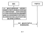
- FIG. 9 is a schematic diagram of a resource configuration method according to an embodiment of the present application. The method includes the following steps.
- Step 901 The base station generates a configuration message, where the configuration message carries information about a symbol used by the relay node to perform backhaul transmission, and the information of the symbol occupied by the backhaul transmission is information of the available symbols transmitted by the base station according to the numerology information and the backhaul. Correspondence between the correspondence and the numerology information of the relay node.
- the correspondence between the numerology information and the information of the available symbols of the backhaul transmission may be a correspondence table between the subcarrier spacing and the number of available symbols or the number of unavailable symbols of the backhaul transmission.
- the correspondence between the numerology information and the information of the available symbols of the backhaul transmission is a correspondence table between the subcarrier spacing and the maximum number of available symbols of the backhaul transmission.
- the subcarrier spacing in Table 2 or 3 can be replaced with other numerology information, such as cyclic prefix, time unit, bandwidth.
- the maximum number of available symbols for backhaul transmissions may also be replaced with information for other available symbols, such as the number of available symbols, the number of unavailable symbols, the propagation delay of the backhaul link, and the switching time of the relay node.
- Step 902 The base station sends a configuration message to the relay node.
- the relay node receives the configuration message.
- the relay node performs backhaul transmission according to the configuration message.
- the base station may implicitly notify the relay node of the maximum number of available symbols for backhaul transmission through the subcarrier interval based on the correspondence between the maximum number of available symbols of the backhaul transmission and the subcarrier spacing (or other numerology). Specifically, the base station may send configuration information of the subcarrier spacing to the relay node, and the relay node may also obtain the maximum number of available symbols according to the predefined correspondence table. If the relay node performs backhaul transmission by default according to the symbol determined by the maximum number of available symbols, the base station does not need to configure the symbol number or symbol number of the backhaul transmission for the relay node. When the relay node moves or the connection is switched, the foregoing correspondence needs to be updated.
- the update method includes the base station configuring a new correspondence relationship for the relay node by using signaling such as RRC, MAC layer CE, or downlink control information (DCI).
- signaling such as RRC, MAC layer CE, or downlink control information (DCI).
- the base station uses the RRC signaling, the MAC layer CE, or the DCI to notify the relay node which specific relationship is adopted.
- the plurality of predefined correspondence tables are mainly related to information such as propagation delay of the backhaul link.
- the method further includes: the base station receiving the information of the backhaul link reported by the relay node; and the base station determining, according to the backhaul link information, a correspondence between the numerology information and the maximum number of available symbols of the backhaul transmission. For example, when the propagation delay of the backhaul link is within a certain interval, it corresponds to a predefined correspondence table. Thereby, a predefined correspondence table can be determined according to the propagation delay of the backhaul link.
- the resource configuration method proposed by the embodiment of the present application can adapt to the situation that the available resources of the backhaul transmission such as the relay node connection handover, the mobile, and the different subcarrier intervals change, and provide the utilization rate of the backhaul transmission resource.
- the embodiment of the present application may divide the function module by using the first device and the second device.
- each function module may be divided according to each function, or two or more functions may be integrated in the function.
- a processing module In a processing module.
- the above integrated modules can be implemented in the form of hardware or in the form of software functional modules. It should be noted that the division of the module in the embodiment of the present application is schematic, and is only a logical function division, and the actual implementation may have another division manner.
- FIG. 10 is a schematic diagram of a possible structure of a first device according to an embodiment of the present disclosure.
- the first device includes: a sending unit 1001 and a receiving unit 1002.
- the sending unit 1001 is configured to support a related step of the first device in the method embodiment to send the first message (or the information of the available symbols).
- the first device performs step 201 in FIG.
- the receiving unit 1002 is configured to support a related step of the first device receiving the second message (or the configuration of the second device regarding the backhaul transmission).
- the first device performs step 202 in FIG.
- the first device further includes: a processing unit 1003, configured to support information about the available symbols of the first device, and related steps about the configuration of the backhaul transmission.
- the processing unit 1003 may be a processor or a processing circuit, etc.; the sending unit 1001 may be a transmitter or a transmitting circuit, etc., the receiving unit 1002 may be a receiver or a receiving circuit, etc., and the sending unit 1001 and the receiving unit 1002 may be Form a communication interface.
- FIG. 11 is a schematic diagram of a possible logical structure of a first device provided by an embodiment of the present application.
- the first device includes a communication interface 1103.
- the communication interface 1103 is configured to support the first device to communicate.
- the communication interface 1103 is configured to support a related step of the first device to send the first message, or a related step of supporting the first device to receive the second device.
- the first device may further include a memory 1101, a bus 1104, and a processor 1102.
- the processor 1102 and the memory 1101 can be connected to one another via a bus 1104.
- the processor 1102 can be used to support the first device's information about the available symbols and the related steps regarding the configuration of the backhaul transmission and the like.
- the memory 1101 is configured to store code and data of the first device.
- FIG. 12 is a schematic diagram of a possible structure of a second device according to an embodiment of the present disclosure.
- the second device includes: a receiving unit 1201 and a sending unit 1202.
- the receiving unit 1201 is configured to support a related step of the second device receiving the first message.
- the sending unit 1202 is configured to support a related step of the second device sending the second message.
- the second device may further include a processing unit 1203.
- the processing unit 1203 is configured to process the information of the available symbols by the second device and/or the related steps of performing the backhaul transmission configuration on the first device.
- the processing unit 1203 may be a processor or a processing circuit, etc.; the sending unit 1202 may be a transmitter or a transmitting circuit, etc., the receiving unit 1201 may be a receiver or a receiving circuit, etc., and the sending unit 1202 and the receiving unit 1201 may be Form a communication interface.
- FIG. 13 is a schematic diagram of a possible logical structure of a second device provided by an embodiment of the present application.
- the second device includes a communication interface 1303.
- the communication interface 1303 is configured to support communication by the second device.
- the communication interface 1303 is configured to support the second device to receive the first message and/or send the second message.
- the second device may further include a memory 1301, a bus 1304, and a processor 1302.
- the processor 1302 and the memory 1301 are connected to one another via a bus 1304.
- the memory 1301 is configured to store program codes and data of the second device.
- the processor 1302 calls the code stored in the memory 1301 for control management.
- the memory 1301 may or may not be coupled to the processor.
- the processor 1102 and the processor 1302 may be a central processing unit, a general purpose processor, a digital signal processor, an application specific integrated circuit, a field programmable gate array or other programmable logic device, a transistor logic device, and a hardware component. Or any combination thereof. It is possible to implement or carry out the various illustrative logical blocks, modules and circuits described in connection with the present disclosure.
- the processor may also be a combination of computing functions, for example, including one or more microprocessor combinations, combinations of digital signal processors and microprocessors, and the like.
- the bus 1104 and the bus 1304 may be peripheral component interconnect standard PCI buses or extended industry standard architecture EISA buses and the like. The bus can be divided into an address bus, a data bus, a control bus, and the like. For ease of representation, only one thick line is shown in FIGS. 11 and 13, but it does not mean that there is only one bus or one type of bus.
- each network element such as the first device, the second device, and the third device, in order to implement the above functions, includes corresponding hardware structures and/or software modules for performing the respective functions.
- the present application can be implemented in a combination of hardware or hardware and computer software in conjunction with the network elements and algorithm steps of the various examples described in the embodiments disclosed herein. Whether a function is implemented in hardware or computer software to drive hardware depends on the specific application and design constraints of the solution. A person skilled in the art can use different methods to implement the described functions for each particular application, but such implementation should not be considered to be beyond the scope of the present application.
- a readable storage medium wherein the readable storage medium stores computer execution instructions, when a device (which may be a single chip microcomputer, a chip, etc.) or the processor can invoke the readable storage medium
- the steps of storing a computer-executable instruction to perform the steps of the first device or the second device in the method provided in FIG. 2 or performing the relay node or base station in the method provided in FIG. 9 are stored therein.
- the aforementioned readable storage medium may include various media that can store program codes, such as a USB flash drive, a removable hard disk, a read only memory, a random access memory, a magnetic disk, or an optical disk.
- a computer program product comprising computer executed instructions stored in a computer readable storage medium; at least one processor of the device may be Reading the storage medium to read the computer execution instructions, the at least one processor executing the computer to execute the instructions such that the device implements the steps of the first device or the second device in the method provided in FIG. 2 or performs the method in the method provided in FIG. The steps of a node or base station.
- a communication system including a plurality of devices including a first device and a second device.
- the first device may be the first device provided in FIG. 10 or FIG. 11 and used to perform the steps of the first device in the method provided in FIG. 2 or FIG. 9; and/or the second device may be FIG. 12 Or the second device provided in FIG. 13 and used to perform the steps of the second device in the method provided in FIG. 2 or 9.
- the embodiment of the present application also provides a chip that implements the method described in the above embodiment (for example, FIG. 2 or FIG. 9).
- the chip includes a processing circuit and a transceiver circuit.
- the transceiver circuit can be, for example, an input/output interface, a pin or a circuit, or the like.
- the processing circuit can execute computer executed instructions stored by the memory unit.
- the chip may also include a memory unit.
- the storage unit may be a register, a cache, or the like. Of course, it is also possible to provide an additional memory unit for the chip.
- the storage unit may also be a storage unit located outside the chip in the terminal or the access device, such as a read-only memory (ROM) or other type of static storage device that can store static information and instructions. Random access memory (RAM), etc.
- the chip can be applied to a base station or a relay node.
- Yet another aspect of the present application is directed to an apparatus that includes code in the processor running memory such that the apparatus performs the various methods described above.
- the memory stores code and data.
- the memory is located in the device, the memory being coupled to the processor.
- the memory can also be located outside of the device.
- the above embodiments it may be implemented in whole or in part by software, hardware, firmware, or any combination thereof.
- software it may be implemented in whole or in part in the form of a computer program product.
- the computer program product includes one or more computer instructions.
- the computer program instructions When the computer program instructions are loaded and executed on a computer, the processes or functions described in accordance with embodiments of the present invention are generated in whole or in part.
- the computer can be a general purpose computer, a special purpose computer, a computer network, or other programmable device.
- the computer instructions can be stored in a computer readable storage medium or transferred from one computer readable storage medium to another computer readable storage medium, for example, the computer instructions can be from a website site, computer, server or data center Transfer to another website site, computer, server, or data center by wire (eg, coaxial cable, fiber optic, digital subscriber line (DSL), or wireless (eg, infrared, wireless, microwave, etc.).
- the computer readable storage medium can be any available media that can be accessed by a computer or a data storage device such as a server, data center, or the like that includes one or more available media.
- the usable medium may be a magnetic medium (eg, a floppy disk, a hard disk, a magnetic tape), an optical medium (eg, a DVD), or a semiconductor medium (such as a solid state disk (SSD)).
Landscapes
- Engineering & Computer Science (AREA)
- Signal Processing (AREA)
- Computer Networks & Wireless Communication (AREA)
- Mobile Radio Communication Systems (AREA)
Abstract
Description
| 配置比特 | 起始符号编号 | 结束符号编号 |
| 00 | 0 | 13 |
| 01 | 0 | 12 |
| 10 | 0 | 11 |
| 11 | 0 | 10 |
| 子载波间隔(Hz) | 120K | 240K | 480K |
| 回程传输的最大可用符号数 | 12 | 11 | 9 |
| 子载波间隔(Hz) | 120K | 240K | 480K |
| 回程传输的最大可用符号数 | 5 | 4 | 2 |
Claims (28)
- 一种资源配置方法,其特征在于,所述方法包括:第一设备向第二设备发送第一消息,所述第一消息携带回程传输的可用符号的信息;其中,所述第一设备包括第一中继节点,所述第二设备包括基站;或者,所述第一设备包括第二中继节点,所述第二设备包括第三中继节点;所述第一设备从所述第二设备接收第二消息,所述第二消息用于指示所述第一设备进行回程传输所占用符号的信息。
- 根据权利要求1所述的方法,其特征在于,所述可用符号的信息包括以下一个或多个:可用符号数、可用符号的编号、不可用符号数、不可用符号的编号、回程链路的传播时延和所述第一设备的收发切换时间。
- 根据权利要求2所述的方法,其特征在于,所述可用符号数由符号时间长度、所述回程链路的传播时延和所述第一设备的收发切换时间来确定。
- 根据权利要求3所述的方法,其特征在于,当所述第一设备和所述第二设备之间帧结构同步时,所述可用符号数N=m-n,其中m为回程传输所在时隙的总符号数,n为满足nT-T p≥T Rx/Tx的n,且n小于m,T表示一个符号的时间长度,T p表示回程传输的传播时延,T Rx/Tx表示所述第一设备的收发切换时间。
- 根据权利要求3所述的方法,其特征在于,当所述第一设备和所述第二设备之间帧结构异步时,所述可用符号数N=m-n,其中m为回程传输所在时隙的总符号数,n为满足nT≥T Rx/Tx的n,且n小于m,T表示一个符号的时间长度,T Rx/Tx表示所述第一设备的收发切换时间。
- 一种资源配置方法,其特征在于,所述方法包括:第二设备从第一设备接收第一消息,所述第一消息携带回程传输的可用符号的信息;所述第二设备向所述第一设备发送第二消息,所述第二消息用于指示所述第一设备进行回程传输所占用符号的信息。
- 根据权利要求6所述的方法,其特征在于,所述可用符号的信息包括以下一个或多个:可用符号数、可用符号的编号、不可用符号数、不可用符号的编号、回程链路的传播时延和所述第一设备的收发切换时间。
- 根据权利要求7所述的方法,其特征在于,所述可用符号数由符号时间长度、所述回程链路的传播时延和所述第一设备的收发切换时间来确定。
- 根据权利要求8所述的方法,其特征在于,当所述第一设备和所述第二设备之间帧结构同步时,所述可用符号数N=m-n,其中m为回程传输所在时隙的总符号数,n为满足nT-T p≥T Rx/Tx的n,且n小于m,T表示一个符号的时间长度,T p表示回程传输的传播时延,T Rx/Tx表示所述第一设备的收发切换时间。
- 根据权利要求8所述的方法,其特征在于,当所述第一设备和所述第二设备之间帧结构异步时,所述可用符号数N=m-n,其中m为回程传输所在时隙的总符号数,n为满足nT≥T Rx/Tx的n,且n小于m,T表示一个符号的时间长度,T p表示回程传输的传播时延,T Rx/Tx表示所述第一设备的收发切换时间。
- 一种用于资源配置的第一设备,其特征在于,所述第一设备包括:发送单元,用于向第二设备发送第一消息,所述第一消息携带回程传输的可用符号的信息;其中,所述第一设备包括第一中继节点,所述第二设备包括基站;或者,所述第一设备包括第二中继节点,所述第二设备包括第三中继节点;接收单元,用于从所述第二设备接收第二消息,所述第二消息用于指示所述第一设备进行回程传输所占用符号的信息。
- 根据权利要求11所述的第一设备,其特征在于,所述可用符号的信息包括以下一个或多个:可用符号数、可用符号的编号、不可用符号数、不可用符号的编号、回程链路的传播时延和所述第一设备的收发切换时间。
- 根据权利要求12所述的第一设备,其特征在于,所述可用符号数由符号时间长度、所述回程链路的传播时延和所述第一设备的收发切换时间来确定。
- 根据权利要求13所述的第一设备,其特征在于,当所述第一设备和所述第二设备之间帧结构同步时,所述可用符号数N=m-n,其中m为回程传输所在时隙的总符号数,n为满足nT-T p≥T Rx/Tx的n,且n小于m,T表示一个符号的时间长度,T p表示回程传输的传播时延,T Rx/Tx表示所述第一设备的收发切换时间。
- 根据权利要求13所述的第一设备,其特征在于,当所述第一设备和所述第二设备之间帧结构异步时,所述可用符号数N=m-n,其中m为回程传输所在时隙的总符号数,n为满足nT≥T Rx/Tx的n,且n小于m,T表示一个符号的时间长度,T Rx/Tx表示所述第一设备的收发切换时间。
- 一种用于资源配置的第二设备,其特征在于,所述第二包括:接收单元,用于从第一设备接收第一消息,所述第一消息携带回程传输的可用符号的信息;发送单元,用于向所述第一设备发送第二消息,所述第二消息用于指示所述第一设备进行回程传输所占用符号的信息。
- 根据权利要求16所述的第二设备,其特征在于,所述可用符号的信息包括以下一个或多个:可用符号数、可用符号的编号、不可用符号数、不可用符号的编号、回程链路的传播时延和所述第一设备的收发切换时间。
- 根据权利要求17所述的第二设备,其特征在于,所述可用符号数由符号时间长度、所述回程链路的传播时延和所述第一设备的收发切换时间来确定。
- 根据权利要求18所述的第二设备,其特征在于,当所述第一设备和所述第二设备之间帧结构同步时,所述可用符号数N=m-n,其中m为回程传输所在时隙的总符号数,n为满足nT-T p≥T Rx/Tx的n,且n小于m,T表示一个符号的时间长度,T p表示回程传输的传播时延,T Rx/Tx表示所述第一设备的收发切换时间。
- 根据权利要求18所述的第二设备,其特征在于,当所述第一设备和所述第二设备之间帧结构异步时,所述可用符号数N=m-n,其中m为回程传输所在时隙的总符号数,n为满足nT≥T Rx/Tx的n,且n小于m,T表示一个符号的时间长度,T p表示回程传输的传播时延,T Rx/Tx表示所述第一设备的收发切换时间。
- 一种资源配置方法,其特征在于,所述方法包括:第二设备生成配置消息,所述配置消息携带为第一设备配置进行回程传输所占用符号的信息,所述进行回程传输所占用符号的信息是所述第二设备根据numerology信息与回程传输的可用符号的信息之间的对应关系以及所述第一设备的numerology信息得到的;所述第二设备向第一设备发送配置消息。
- 一种资源配置方法,其特征在于,所述方法包括:第一设备从第二设备接收所述配置消息,所述配置消息携带为第一设备配置进行回程传输所占用符号的信息,所述进行回程传输所占用符号的信息是所述第二设备根据numerology信息与回程传输的可用符号的信息之间的对应关系以及所述第一设备的numerology信息得到的;所述第一设备根据所述配置消息进行回程传输。
- 一种第一设备,其特征在于,所述第一设备包括:接收单元,用于从第二设备接收所述配置消息,所述配置消息携带为第一设备配置进行回程传输所占用符号的信息,所述进行回程传输所占用符号的信息是所述第二设备根据numerology信息与回程传输的可用符号的信息之间的对应关系以及所述第一设备的numerology信息得到的;处理单元,用于根据所述配置消息进行回程传输。
- 一种第二设备,其特征在于,所述第二设备包括:处理单元,用于生成配置消息,所述配置消息携带为第一设备配置进行回程传输所占用符号的信息,所述进行回程传输所占用符号的信息是所述第二设备根据numerology信息与回程传输的可用符号的信息之间的对应关系以及所述第一设备的numerology信息得到的;发送单元,用于向所述第一设备发送配置消息。
- 一种设备,其特征在于,所述设备包括收发器和处理器;所述处理器运行存储器中的代码使得所述设备执行权利要求1-10、21、22任一项所述的方法。
- 一种可读存储介质,其特征在于,所述可读存储介质中存储有指令;当所述可读存储介质中存储的指令在设备上运行时,使得所述设备执行权利要求1-10、21、22任一项所述的方法。
- 一种计算机程序产品,其特征在于,当所述计算机程序产品在计算机上运行时,使得所述计算机执行执行权利要求1-10、21、22任一项所述的方法。
- 一种芯片,其特征在于,所述芯片包括通信接口和处理器;所述通信接口进行消息的接收和/或发送。所述处理器运行存储器中的代码使得所述芯片执行权利要求1-10、21、22任一项所述的方法。
Priority Applications (3)
| Application Number | Priority Date | Filing Date | Title |
|---|---|---|---|
| BR112020011369-7A BR112020011369A2 (pt) | 2017-12-08 | 2018-12-07 | método e dispositivo de configuração de recurso, meio de armazenamento, produto, e chip de computador |
| EP18885955.7A EP3716500A4 (en) | 2017-12-08 | 2018-12-07 | RESOURCE ALLOCATION PROCESS AND DEVICE |
| US16/894,077 US20200304255A1 (en) | 2017-12-08 | 2020-06-05 | Resource configuration method and apparatus |
Applications Claiming Priority (2)
| Application Number | Priority Date | Filing Date | Title |
|---|---|---|---|
| CN201711297552.3A CN109905160B (zh) | 2017-12-08 | 2017-12-08 | 一种资源配置方法和装置 |
| CN201711297552.3 | 2017-12-08 |
Related Child Applications (1)
| Application Number | Title | Priority Date | Filing Date |
|---|---|---|---|
| US16/894,077 Continuation US20200304255A1 (en) | 2017-12-08 | 2020-06-05 | Resource configuration method and apparatus |
Publications (1)
| Publication Number | Publication Date |
|---|---|
| WO2019110011A1 true WO2019110011A1 (zh) | 2019-06-13 |
Family
ID=66750415
Family Applications (1)
| Application Number | Title | Priority Date | Filing Date |
|---|---|---|---|
| PCT/CN2018/119843 Ceased WO2019110011A1 (zh) | 2017-12-08 | 2018-12-07 | 一种资源配置方法和装置 |
Country Status (5)
| Country | Link |
|---|---|
| US (1) | US20200304255A1 (zh) |
| EP (1) | EP3716500A4 (zh) |
| CN (1) | CN109905160B (zh) |
| BR (1) | BR112020011369A2 (zh) |
| WO (1) | WO2019110011A1 (zh) |
Families Citing this family (8)
| Publication number | Priority date | Publication date | Assignee | Title |
|---|---|---|---|---|
| CN110545581B (zh) * | 2018-05-29 | 2021-12-24 | 上海朗帛通信技术有限公司 | 一种被用于无线通信的节点中的方法和装置 |
| US12232126B2 (en) * | 2019-04-02 | 2025-02-18 | Apple Inc. | Resource allocation for repeated uplink transmissions |
| US12107661B2 (en) | 2019-08-01 | 2024-10-01 | Qualcomm Incorporated | Control method for smart repeaters |
| US12101165B2 (en) | 2019-08-01 | 2024-09-24 | Qualcomm Incorporated | Access procedure of smart directional repeaters |
| US12047999B2 (en) | 2019-08-01 | 2024-07-23 | Qualcomm Incorporated | Access procedure configuration of a millimeter wave repeater |
| CN110536466A (zh) * | 2019-08-16 | 2019-12-03 | 中兴通讯股份有限公司 | 数据传输方法、装置和系统 |
| US12309830B2 (en) * | 2020-03-23 | 2025-05-20 | Qualcomm Incorporated | Access procedure configuration of a millimeter wave repeater |
| CN118283797A (zh) * | 2022-12-30 | 2024-07-02 | 中国移动通信有限公司研究院 | 一种链路的传输配置方法、网络设备及存储介质 |
Citations (4)
| Publication number | Priority date | Publication date | Assignee | Title |
|---|---|---|---|---|
| CN102801461A (zh) * | 2011-05-26 | 2012-11-28 | 中兴通讯股份有限公司 | 下行回程子帧结构配置方法及系统 |
| US20130039254A1 (en) * | 2010-05-07 | 2013-02-14 | Lg Electronics Inc. | Method for backhaul subframe setting between a base station and a relay node in a wireless communication system and a device therefor |
| CN103391618A (zh) * | 2012-05-09 | 2013-11-13 | 中兴通讯股份有限公司 | 子帧配置方法及装置 |
| US20170265187A1 (en) * | 2016-03-11 | 2017-09-14 | Qualcomm Incorporated | Relay for enhanced machine type communication and narrow band-internet of things |
Family Cites Families (10)
| Publication number | Priority date | Publication date | Assignee | Title |
|---|---|---|---|---|
| US8027308B1 (en) * | 2007-10-26 | 2011-09-27 | Sprint Communications Company L.P. | Method of optimizing handoff time in a wireless telecommunication network through dynamic data source control |
| CN101459581B (zh) * | 2007-12-12 | 2014-12-10 | 中国移动通信集团公司 | 资源调度的方法、装置及一种通信系统 |
| WO2010107234A2 (ko) * | 2009-03-17 | 2010-09-23 | 한국전자통신연구원 | 릴레이를 포함하는 무선 통신 시스템의 데이터 전송 방법 |
| KR101295584B1 (ko) * | 2009-04-09 | 2013-09-03 | 엘지전자 주식회사 | 릴레이 방식의 통신 시스템에서 신호 전송 방법 및 장치 |
| CN101938794A (zh) * | 2009-07-02 | 2011-01-05 | 华为技术有限公司 | 无线自回程传输的切换处理方法及装置 |
| CN102036399B (zh) * | 2009-09-29 | 2014-08-13 | 中兴通讯股份有限公司 | 一种在回程链路发送上行控制信息的方法 |
| CN102045103B (zh) * | 2009-10-26 | 2013-09-04 | 中国移动通信集团公司 | 一种在中继系统中进行收发转换的方法及设备 |
| CN102148784B (zh) * | 2010-02-10 | 2013-09-18 | 中国移动通信集团公司 | 中继系统中基站与中继站之间通信的方法、系统及装置 |
| EP2629473B1 (en) * | 2010-10-13 | 2019-04-24 | LG Electronics Inc. | Method of transmitting control information and device for same |
| WO2012138112A2 (ko) * | 2011-04-04 | 2012-10-11 | 엘지전자 주식회사 | 무선 통신 시스템에서 상향링크 제어 정보를 전송하는 방법 및 이를 위한 장치 |
-
2017
- 2017-12-08 CN CN201711297552.3A patent/CN109905160B/zh active Active
-
2018
- 2018-12-07 BR BR112020011369-7A patent/BR112020011369A2/pt unknown
- 2018-12-07 WO PCT/CN2018/119843 patent/WO2019110011A1/zh not_active Ceased
- 2018-12-07 EP EP18885955.7A patent/EP3716500A4/en active Pending
-
2020
- 2020-06-05 US US16/894,077 patent/US20200304255A1/en not_active Abandoned
Patent Citations (4)
| Publication number | Priority date | Publication date | Assignee | Title |
|---|---|---|---|---|
| US20130039254A1 (en) * | 2010-05-07 | 2013-02-14 | Lg Electronics Inc. | Method for backhaul subframe setting between a base station and a relay node in a wireless communication system and a device therefor |
| CN102801461A (zh) * | 2011-05-26 | 2012-11-28 | 中兴通讯股份有限公司 | 下行回程子帧结构配置方法及系统 |
| CN103391618A (zh) * | 2012-05-09 | 2013-11-13 | 中兴通讯股份有限公司 | 子帧配置方法及装置 |
| US20170265187A1 (en) * | 2016-03-11 | 2017-09-14 | Qualcomm Incorporated | Relay for enhanced machine type communication and narrow band-internet of things |
Non-Patent Citations (1)
| Title |
|---|
| See also references of EP3716500A4 * |
Also Published As
| Publication number | Publication date |
|---|---|
| US20200304255A1 (en) | 2020-09-24 |
| EP3716500A4 (en) | 2021-01-27 |
| EP3716500A1 (en) | 2020-09-30 |
| CN109905160B (zh) | 2022-03-29 |
| CN109905160A (zh) | 2019-06-18 |
| BR112020011369A2 (pt) | 2020-11-17 |
Similar Documents
| Publication | Publication Date | Title |
|---|---|---|
| WO2019110011A1 (zh) | 一种资源配置方法和装置 | |
| US11265903B2 (en) | Uplink transmission method and apparatus | |
| CN110401515B (zh) | 一种资源配置方法及节点 | |
| CN112399585B (zh) | 一种资源复用方法及装置 | |
| AU2018401518B2 (en) | Transmission configuration method and related product | |
| KR102071535B1 (ko) | 무선 통신 시스템에서 매크로 셀과 스몰 셀 간 스위칭을 위한 자원 할당 장치 및 방법 | |
| CN110768768B (zh) | 探测参考信号的资源配置方法及通信装置 | |
| WO2019091488A1 (zh) | 一种上行传输方法及终端 | |
| CN109150379B (zh) | 一种通信方法、网络设备及终端设备 | |
| CN110611957A (zh) | 一种信号传输方法及装置 | |
| CN110167174B (zh) | 一种中继传输方法及装置 | |
| CN111436085B (zh) | 通信方法及装置 | |
| JP2023554474A (ja) | 情報伝送方法、装置、iabノード及びネットワーク機器 | |
| CN109151955B (zh) | 一种通信方法及设备 | |
| EP4185050A1 (en) | Communication method and device | |
| CN112584518A (zh) | 一种资源确定方法及装置 | |
| JP2016518062A (ja) | 二重接続をサポートするための方法および装置 | |
| JP2023523804A (ja) | リンク状態の変換方法及び通信機器 | |
| CN112235869B (zh) | 数据传输方法和设备 | |
| US10944625B2 (en) | Bearer configuration method and related products | |
| WO2019157982A1 (zh) | 一种中继传输方法及装置 | |
| CN113677010A (zh) | 资源复用方法及装置 | |
| CN111756509B (zh) | 一种传输公共信号块的方法和装置 | |
| CN117413590A (zh) | 用于确定srs天线切换的保护时段位置的方法和装置 | |
| WO2018233697A1 (zh) | 一种检测下行控制信道的方法及设备 |
Legal Events
| Date | Code | Title | Description |
|---|---|---|---|
| 121 | Ep: the epo has been informed by wipo that ep was designated in this application |
Ref document number: 18885955 Country of ref document: EP Kind code of ref document: A1 |
|
| NENP | Non-entry into the national phase |
Ref country code: DE |
|
| ENP | Entry into the national phase |
Ref document number: 2018885955 Country of ref document: EP Effective date: 20200623 |
|
| REG | Reference to national code |
Ref country code: BR Ref legal event code: B01A Ref document number: 112020011369 Country of ref document: BR |
|
| ENP | Entry into the national phase |
Ref document number: 112020011369 Country of ref document: BR Kind code of ref document: A2 Effective date: 20200605 |