WO2019111308A1 - 空気調和機の室内機 - Google Patents
空気調和機の室内機 Download PDFInfo
- Publication number
- WO2019111308A1 WO2019111308A1 PCT/JP2017/043574 JP2017043574W WO2019111308A1 WO 2019111308 A1 WO2019111308 A1 WO 2019111308A1 JP 2017043574 W JP2017043574 W JP 2017043574W WO 2019111308 A1 WO2019111308 A1 WO 2019111308A1
- Authority
- WO
- WIPO (PCT)
- Prior art keywords
- angle
- indoor unit
- louver
- air conditioner
- air
- Prior art date
- Legal status (The legal status is an assumption and is not a legal conclusion. Google has not performed a legal analysis and makes no representation as to the accuracy of the status listed.)
- Ceased
Links
Images


Classifications
-
- F—MECHANICAL ENGINEERING; LIGHTING; HEATING; WEAPONS; BLASTING
- F24—HEATING; RANGES; VENTILATING
- F24F—AIR-CONDITIONING; AIR-HUMIDIFICATION; VENTILATION; USE OF AIR CURRENTS FOR SCREENING
- F24F1/00—Room units for air-conditioning, e.g. separate or self-contained units or units receiving primary air from a central station
- F24F1/0007—Indoor units, e.g. fan coil units
- F24F1/0011—Indoor units, e.g. fan coil units characterised by air outlets
- F24F1/0014—Indoor units, e.g. fan coil units characterised by air outlets having two or more outlet openings
-
- F—MECHANICAL ENGINEERING; LIGHTING; HEATING; WEAPONS; BLASTING
- F24—HEATING; RANGES; VENTILATING
- F24F—AIR-CONDITIONING; AIR-HUMIDIFICATION; VENTILATION; USE OF AIR CURRENTS FOR SCREENING
- F24F1/00—Room units for air-conditioning, e.g. separate or self-contained units or units receiving primary air from a central station
- F24F1/0007—Indoor units, e.g. fan coil units
- F24F1/0043—Indoor units, e.g. fan coil units characterised by mounting arrangements
- F24F1/0047—Indoor units, e.g. fan coil units characterised by mounting arrangements mounted in the ceiling or at the ceiling
-
- F—MECHANICAL ENGINEERING; LIGHTING; HEATING; WEAPONS; BLASTING
- F24—HEATING; RANGES; VENTILATING
- F24F—AIR-CONDITIONING; AIR-HUMIDIFICATION; VENTILATION; USE OF AIR CURRENTS FOR SCREENING
- F24F11/00—Control or safety arrangements
- F24F11/50—Control or safety arrangements characterised by user interfaces or communication
- F24F11/56—Remote control
-
- F—MECHANICAL ENGINEERING; LIGHTING; HEATING; WEAPONS; BLASTING
- F24—HEATING; RANGES; VENTILATING
- F24F—AIR-CONDITIONING; AIR-HUMIDIFICATION; VENTILATION; USE OF AIR CURRENTS FOR SCREENING
- F24F11/00—Control or safety arrangements
- F24F11/70—Control systems characterised by their outputs; Constructional details thereof
- F24F11/72—Control systems characterised by their outputs; Constructional details thereof for controlling the supply of treated air, e.g. its pressure
- F24F11/74—Control systems characterised by their outputs; Constructional details thereof for controlling the supply of treated air, e.g. its pressure for controlling air flow rate or air velocity
-
- F—MECHANICAL ENGINEERING; LIGHTING; HEATING; WEAPONS; BLASTING
- F24—HEATING; RANGES; VENTILATING
- F24F—AIR-CONDITIONING; AIR-HUMIDIFICATION; VENTILATION; USE OF AIR CURRENTS FOR SCREENING
- F24F11/00—Control or safety arrangements
- F24F11/70—Control systems characterised by their outputs; Constructional details thereof
- F24F11/72—Control systems characterised by their outputs; Constructional details thereof for controlling the supply of treated air, e.g. its pressure
- F24F11/79—Control systems characterised by their outputs; Constructional details thereof for controlling the supply of treated air, e.g. its pressure for controlling the direction of the supplied air
-
- F—MECHANICAL ENGINEERING; LIGHTING; HEATING; WEAPONS; BLASTING
- F24—HEATING; RANGES; VENTILATING
- F24F—AIR-CONDITIONING; AIR-HUMIDIFICATION; VENTILATION; USE OF AIR CURRENTS FOR SCREENING
- F24F13/00—Details common to, or for air-conditioning, air-humidification, ventilation or use of air currents for screening
- F24F13/08—Air-flow control members, e.g. louvres, grilles, flaps or guide plates
- F24F13/10—Air-flow control members, e.g. louvres, grilles, flaps or guide plates movable, e.g. dampers
- F24F13/14—Air-flow control members, e.g. louvres, grilles, flaps or guide plates movable, e.g. dampers built up of tilting members, e.g. louvre
Definitions
- an indoor unit of an air conditioner provided with a plurality of outlets (for example, four), and in such an indoor unit, a plurality of indoor units to improve the temperature unevenness in the heating operation.
- a stirring operation of air is performed by setting the blowing directions of the heated air blown out from the blowout port to different wind directions.
- the louver angle of some of the outlets is not used in normal operation, the opening area is narrowed, the air volume is concentrated on the remaining outlets, and the wind speed is increased. There is also.
- patent documents 1 As this kind of prior art, there is a thing as described in patent 6135734 (patent documents 1), in the thing of this patent document 1, when indoor load is high at the time of heating operation, it is one of the blow-out mouth of an indoor unit. Set the louver to the air flow block position to rotate the louver to a larger angle than the maximum downward blowing position so as to reduce the opening area, and control the louvers of the remaining air outlets to the horizontal blowing position. There is.
- the air flow block position is a position at which the louver's blades further penetrate into the air outlet from the maximum angle (down blow) which the louver normally uses. With this configuration, the flow path of the air flow is blocked by the louver blades. At the outlet where the louver is at the air flow block position, the amount of air blown out is greatly reduced, so that the wind speed at the remaining outlets can be increased, and the blown air can reach farther than usual.
- An object of the present invention is to provide an indoor unit of an air conditioner capable of suppressing deflection of a louver provided at each outlet while enabling high-speed blowing from a part of the outlets of the plurality of outlets. It is.
- the present invention relates to an indoor unit of an air conditioner comprising: a plurality of outlets; and a plurality of louvers provided in the outlets and configured to be able to adjust the blowing direction.
- the louver is turned in the closing direction of the air outlet, and the louver angle at the time of stopping the indoor unit rotated in the closing direction of the air outlet is the fully closed angle.
- a remote control for setting the operation of the louver wherein a minimum angle of the louver angles that can be set by the remote control is a first angle, and a maximum angle is a second angle, the predetermined operation determined in advance
- the louver angle of some of the plurality of the outlets is set to a third angle which is larger than the fully closed angle which is the louver angle when the indoor unit is stopped and smaller than the first angle.
- Another feature of the present invention is an indoor unit of an air conditioner comprising a plurality of outlets and a plurality of louvers provided in the outlets and configured to be adjustable in the direction of blowing.
- the louver is turned in the direction to close the outlet, and the louver angle at the time of stopping the indoor unit rotated in the direction to close the outlet is a fully closed angle, and the louver is turned When it has an auto-swing function, and the minimum angle of the louver at the time of the automatic swing is a first angle, and the maximum angle is a second angle, in a predetermined operation condition determined in advance, among the plurality of air outlets
- the louver angle of a part of the outlets is set to a third angle which is larger than the fully closed angle which is the louver angle at the time of stopping the indoor unit and smaller than the first angle; Swing or It is to be set to any angle.
- an indoor unit of an air conditioner capable of suppressing deflection of a louver provided at each of the outlets while enabling high-speed blowing from a part of the outlets of the plurality of outlets.
- FIG. 3 is a cross-sectional view of one essential part of the air outlet shown in FIG. 1 and FIG. 2, in which the louver is in a fully closed state.
- FIG. 1 shows the minimum angle (1st angle) and the maximum angle (2nd angle) of the louver in operation of an indoor unit by one principal part sectional view of the blower outlet shown to FIG. 1, FIG.
- FIG. 1 shows the minimum angle (1st angle) and the maximum angle (2nd angle) of the louver in operation of an indoor unit by one principal part sectional view of the blower outlet shown to FIG. 1, FIG.
- FIG. 1 shows the minimum angle (1st angle) and the maximum angle (2nd angle) of the louver in operation of an indoor unit by one principal part sectional view of the blower outlet shown to FIG. 1, FIG.
- FIG. 1 shows the minimum angle (1st angle) and the maximum angle (2nd angle) of the louver in operation of an indoor unit by one principal part sectional view of the blower outlet shown to FIG. 1, FIG.
- FIG. 1 shows the 3r
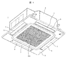
- FIG. 1 is a perspective view showing the indoor unit of the air conditioner of the first embodiment.
- the indoor unit 1 of the air conditioner is connected to an outdoor unit (not shown) by a refrigerant pipe to form a refrigerant circuit, and the refrigerant is circulated to form a refrigeration cycle.
- the indoor unit 1 is a so-called ceiling cassette type, and includes a casing 2 embedded in a ceiling or the like in the room, and a decorative panel 3 provided to close the lower surface opening of the casing 2.
- the suction grille 6 is provided in the said suction port 4, Moreover, the louver 7 which adjusts the blowing direction of the air which each blows off from the said blower outlet 5 is rotatably provided in each said blower outlet 5.
- the louver 7 shown in FIG. 1 shows a state in which the indoor unit 1 is stopped and fully closed, that is, a state in which the louver angle is a fully closed angle (0 degree).
- the fully closed state includes not only the state in which the blowout port 5 is completely closed, but also the state in which the louver is substantially horizontal and the opening area is minimized so as to substantially close the blowout port.
- FIG. 2 is a longitudinal sectional view of the indoor unit 1 shown in FIG.
- a motor 8 and a centrifugal fan 9 connected to a rotational shaft of the motor 8 are installed at a central portion in the housing 2.
- the motor 8 is fixed at the center of the top plate of the housing 2.
- a heat exchanger 10 shaped like a square in plan view is installed around the centrifugal fan 9 so as to surround the centrifugal fan 9.
- the heat exchanger 10 is a cross fin type fin and tube heat exchanger.
- a drain pan 11 for receiving dew condensation water generated in the heat exchanger 10 is installed at the lower part of the heat exchanger 10.
- a heat insulating material made of expanded polystyrene is used as the drain pan 11, and a water receiving groove is formed along the lower end of the heat exchanger 10, and the lower end portion of the heat exchanger 10 enters the water receiving groove.
- the air outlet 5 is formed of a heat insulating material that is integral with or separate from the heat insulating material that constitutes the drain pan 11.
- Reference numeral 20 denotes a ceiling of the room, and the indoor unit 1 is installed with the portion of the housing 2 embedded in the ceiling 20.
- the decorative panel 3 is formed in a square shape that is slightly larger than the housing 2 and is disposed along the ceiling 20 so as to cover the lower surface of the housing 2 and is exposed to the indoor space.
- the louver 7 provided at the outlet 5 of the decorative panel 3 is in the fully closed position (louver angle is 0 degree) in FIG. 2 and shows a state in which the operation of the indoor unit 1 is stopped. .
- the louver 7 is rotated so as to open the outlet 5, and fixed at a predetermined angle set by the user from a remote control (not shown), such as downward blowing or side blowing Be done.
- a remote control not shown
- the louver 7 performs the auto swing operation in the range from the minimum angle to the maximum angle.
- the louver 7 when the louver 7 is set at the downward blowing angle, the conditioned air is blown downward, and when the louver 7 is set at the lateral blowing angle, the air is blown out in the lateral direction (horizontal direction). Furthermore, when the automatic swing is set as described above, the louver 7 performs an automatic swing operation in the range from the minimum angle to the maximum angle, so that the conditioned air is vertical from a nearly horizontal direction according to the movement of the louver 7 It blows out to the direction close to. In FIG.
- reference numeral 15 denotes a bell mouth disposed below the centrifugal fan 9 and having an opening which rises toward the suction portion 12 of the centrifugal fan 9 while gradually reducing the diameter at the central portion,
- the bell mouth 15 is for guiding the air sucked from the suction port 4 to the centrifugal fan 9. Further, the bell mouth 15 divides the internal space of the housing 2 into a suction side and a blow side of the centrifugal fan 9 together with the drain pan 11.
- An electrical equipment box 16 stores control boards and the like for controlling the operation of the indoor unit 1, and the electrical equipment box 16 is installed on the lower surface of the bell mouth 15.
- Reference numeral 17 denotes a suction filter installed on the upper side of the suction grille 6.
- FIG. 3 is a cross-sectional view of one of the main parts of the air outlet shown in FIGS. 1 and 2, in which the louver is in a fully closed angle state.
- the louver 7 is in the state of the fully closed angle shown in FIG. 3 to prevent foreign matter from entering the indoor unit while the indoor unit 1 is stopped and stopping the indoor unit. I improve the design at the time.
- the fully closed angle (0 degree) of the louver 7 is generally not in the state of completely closing the blowout port 5 as shown in FIG. 3, but forming the blowout port 5 with the left end and right end of the louver 7 A slight gap is formed between the wall surface of the decorative panel 3 and the wall surface of the louver 7 and the air outlet 5 so as not to interfere with each other.
- 3a is a heat insulating material, such as a product made of expanded polystyrene which forms the said blower outlet 5. As shown in FIG.
- the louver 7 is formed in an elongated plate or wing shape extending from one end to the other in the longitudinal direction of the blowout port 5, and the louver 7 has a central axis extending in the longitudinal direction It is fixed to 18 via the mounting member 19.
- the central shaft 18 is rotatably supported by support members (not shown) disposed at both ends thereof, and its rotation is controlled by a stepping motor or the like.
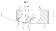
- FIG. 4 is a cross-sectional view of one of the main parts of the air outlet shown in FIGS. 1 and 2, showing the minimum angle and the maximum angle of the louver during the operation of the indoor unit. That is, FIG. 4 shows the operation range of the louver 7 in a state where the indoor unit 1 is in operation, and the louver 7a shown by a solid line is the minimum angle of the louver 7 which can be set by the user with a remote control (not shown). A (first angle) is shown, and a louver 7b indicated by an alternate long and short dash line indicates a maximum angle (second angle) of the louver 7 which can be set by the user with the remote controller.
- the louver 7 When the louver 7 is set to the position 7a of the minimum angle (first angle), the conditioned air blown out from the blowout port 5 is a side-blowing operation in which the air is blown out in a substantially horizontal direction. On the other hand, when the louver 7 is set to the position 7b at the maximum angle (second angle), the conditioned air blown out from the blowout port 5 is in a downward blowing operation where it is blown out in a substantially vertical direction.
- the minimum angle (first angle) is 28 degrees, for example.
- the second angle) is, for example, 64 degrees.
- the minimum angle (first angle) may be set arbitrarily within a range of, for example, 27 to 30 degrees.
- the maximum angle (second angle) may be set arbitrarily within a range of, for example, about 60 to 70 degrees.
- the angle of the louver 7 during the operation of the indoor unit 1 can be set not only from the remote control to the above-mentioned minimum and maximum angles, but also from the remote control from multiple steps in several degrees between the above-mentioned minimum and maximum angles It is configured to be configurable.
- the minimum angle is set to the first step
- the maximum angle is set to the seventh step
- an angle of five steps (second to sixth steps) can be set between the first and seventh steps.
- the angle of the louver 7 is not limited to seven, and may be larger or smaller.
- the louver angle may be set to an arbitrary angle in a stepless manner.
- the louver 7 sets the angle at the start of the auto swing setting, for example, the maximum angle from the first step which is the minimum angle to the second step, the third step,.
- the reciprocation operation is repeated to increase to the seventh stage, and then sequentially decrease in the reverse direction to the sixth stage, the fifth stage, and so on to the first stage of the minimum angle.
- the auto swing is not limited to the reciprocating operation between the first and seventh stages, and may be configured to reciprocate, for example, the third and seventh stages.
- the louver angle can be configured to change steplessly and smoothly.
- the wind direction is lowered so that warm air is supplied downward during high load operation where the temperature difference between the outside air temperature and the room temperature is very large.
- blowing is performed, there is a case where the blowing air can not sufficiently reach the floor surface.
- FIG. 7 is a sectional view of an essential part for explaining a conventional indoor unit in which the louver 7 is turned to the air flow block position.
- the louver 7 of a portion of the blowout port 5 of the indoor unit 1 is positioned at the maximum lower blowing position (1 in FIG. 4) so as to reduce the opening area of the blowout port. It is made to rotate to a still larger angle than the position of the maximum angle shown with a dashed dotted line.
- the louver 7 is at the air outlet 5 of the decorative panel 3 and the air outlet 5 of the drain pan 11 (see FIG. 2). It penetrates deeply and interferes with the heat insulating material 3a forming the blowout port, or the heat insulating material forming the blowout port 5 of the portion of the drain pan 11.
- louver 7 does not interfere with the wall surface of the air outlet 5 formed of a heat insulating material or the like, it is not necessary to change the internal structure of the air outlet 5 near the louver 7.
- louvers 7 of some of the outlets 5 being in the fully closed position
- the louvers in the fully closed position are largely bent by the wind pressure of the blown air and the blown air is hot.
- the louver made of resin has a problem that it tends to cause plastic deformation when it is operated for a long time.
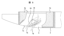
- FIG. 5 is a cross-sectional view of one of the main parts of the air outlet shown in FIGS. 1 and 2, illustrating the third angle of the louver in the first embodiment
- FIG. 6 shows the state of the third angle of the louver shown in FIG. It is a figure explaining an operation in.
- the position 7a of the louver 7 indicated by the alternate long and short dash line shows the case where the louver 7 is set at the position of the minimum angle (first angle), and the position 7b of the louver 7 similarly indicated by the alternate long and short dash line
- the case where the louver 7 is set at the position of the maximum angle (second angle) is shown.
- Positions 7a and 7b of these louvers 7 are angles of the louvers 7 which can be set from a remote controller (not shown), which is a function generally provided to a conventional indoor unit.
- the louver 7 is generally provided with a function of auto-swing in the range of the first angular position 7a to the second angular position, and can be set from a remote controller.
- the angles of the respective louvers 7 at the four outlets 5 shown in FIG. It is configured to be set to a position 7c of a third angle which is larger than a degree and smaller than a first angle which is a minimum opening degree of the louver 7 which can be set from the remote controller.
- the position 7c at the third angle of the louver 7 is not an angle that can be set by the user from the remote control, but the indoor unit 1 of the air conditioner or the like under a predetermined operation condition defined in advance such as at the start of the heating operation.
- the angular position of the louver 7 is automatically set from the provided control device. For example, when the first angle is 28 degrees, the third angle is larger than 0 degrees, which is a fully closed angle when the indoor unit is stopped, and the first angle which is the minimum angle that the user can set from the remote control It is set to an angle smaller than 28 degrees, for example, 14 degrees.
- the third angle is not limited to 14 degrees, and may be set arbitrarily in the range of 5 to 25 degrees.
- each louver 7 is configured to be able to be set at the position 7c of the third angle (0.5th step angle), and the air conditioner performs a predetermined operation determined in advance.
- the louvers 7 of the plurality of outlets 5 are set to the position 7c at the third angle under the conditions.
- the louvers 7 of some of the outlets 5 are set at the position of the third angle (the angle larger than the fully closed angle of the louvers but smaller than the first angle), as shown by hatching circles in FIG.
- a small gap 21 can be formed between the wall surface of the outlet 5 and the end of the louver 7. Therefore, since the air flow can be blown out from the gap 21, the deflection of the louver due to the wind pressure can be reduced. Therefore, since the deflection of the louver 7 can be suppressed to a small value, plastic deformation of the louver can be suppressed even when high temperature air is blown out into the room.
- the louvers 7 set to the third angle may be configured to be sequentially switched at predetermined time intervals.
- the louvers 7 of the other outlets 5 are louver operations that can be set from the remote control. That is, the other louvers 7 are set to the automatic swing or set to an arbitrary louver angle.
- the predetermined predetermined operating condition of the air conditioner is, for example, the following operating condition, and when the following operation is performed, a part of the outlets of the louvers of the plurality of outlets.
- the louver may be automatically set to the third angle from, for example, a control device (not shown) provided in the indoor unit 1.
- a predetermined temperature difference which is predetermined, during heating operation or cooling operation.
- the high-speed blowout setting is made to allow the blowout air to reach far from the normal such as near the floor surface.
- the stirring operation is set to increase the blowing air velocity and reduce the temperature difference between the upper and lower portions of the room during heating operation or the control device of the air conditioner automatically executes the stirring operation If.
- the third angle is not allowing the user to set an arbitrary louver to the third angle from the remote control, and the air conditioning is performed when the high-speed blowout setting or the like is performed.
- This is an angle that is automatically set from the machine control unit. For example, when one of the operations (1), (3), and (4) described above is set, or when the operation is performed under the conditions of the above (2), the stirring operation of the above (4) is automatically executed. In this case, the angle of the louver 7 of any of the outlets 5 is automatically set to the third angular position from the control device.
- the opening area of the blowout port 5 of the louver portion set at the third angle is reduced, so the volume of air blown out from the blowout port 5 is significantly reduced. It is possible to sufficiently increase the wind speed from the air. Therefore, the blown air can reach a sufficiently distant position such as a floor surface.
- the small gap 21 described above can be formed between the wall surface of the blowout port 5 and the end of the louver 7. Since the air flow can be blown out from the above, the deflection of the louver 7 due to the wind pressure can be reduced. Therefore, even if a large amount of high temperature air is blown into the room by increasing the rotational speed of the centrifugal fan 9, the deflection of the louver 7 can be reduced, and therefore the plastic deformation of the louver 7 can be suppressed.
- the angle of the louver of a part of the plurality of the outlets is set to the third angle when a predetermined operation condition is reached.
- it may be configured as follows. That is, when the predetermined operation condition is reached, the angle of the louver 7 of a part of the plurality of air outlets 5 is not immediately controlled to the third angle, and the louver 7 is plastic first Alternatively, the louver 7 may be first controlled to the third angle after the predetermined time has elapsed after the predetermined closing time is maintained for a predetermined time that does not cause deformation.
- the minimum angle which can be set by the remote control is the first angle
- the louver angle which is larger than the fully closed angle which is the louver angle when the indoor unit is stopped and smaller than the first angle may be configured as follows. That is, if the louver has the function of causing the automatic swing, the minimum angle of the louver at the time of the automatic swing is taken as the first angle, which is larger than the fully closed angle which is the louver angle at the time of stopping the indoor unit and smaller than the first angle.
- the louver angle may be set to the third angle. In this case, the louvers of the other outlets 5 provided with louvers other than the louvers set to the third angle are set to an automatic swing or an arbitrary angle.
- the angle of the louver 7 of a part of the plurality of the blowout ports 5 under a predetermined operation condition set in advance for example, when the high speed blowout setting is made Is set to a third angle which is larger than the fully closed angle (0 degree) which is the louver angle when the indoor unit is stopped and which can be set by the remote control or smaller than the first angle which is the minimum angle when Since the louvers 7 of the air outlet are configured to perform louver operation that can be set from the remote controller, they are provided at each air outlet 5 while enabling high-speed air outlet from some air outlets of the plurality of air outlets 5 There is an effect that it is possible to obtain the indoor unit of the air conditioner that can also suppress the deflection of the louver 7 that is being performed.
Landscapes
- Engineering & Computer Science (AREA)
- Chemical & Material Sciences (AREA)
- Combustion & Propulsion (AREA)
- Mechanical Engineering (AREA)
- General Engineering & Computer Science (AREA)
- Human Computer Interaction (AREA)
- Physics & Mathematics (AREA)
- Fluid Mechanics (AREA)
- Air Conditioning Control Device (AREA)
- Air-Flow Control Members (AREA)
- Air Filters, Heat-Exchange Apparatuses, And Housings Of Air-Conditioning Units (AREA)
Abstract
Description
まず、図1を用いて本実施例1における空気調和機の室内機の全体構成を説明する。図1は、本実施例1の空気調和機の室内機を示す斜視図である。
なお、図2において、15は前記遠心ファン9の下方に配置され、中央部に徐々に径を小さくしながら前記遠心ファン9の吸込部12に向けて立ち上がった開口部をもつベルマウスであり、このベルマウス15は前記吸込口4から吸い込まれた空気を前記遠心ファン9に案内するためのものである。また、前記ベルマウス15は、前記ドレンパン11と共に、前記筐体2の内部空間を、前記遠心ファン9の吸込側と吹出側に仕切っている。
なお、図3において、3aは前記吹出口5を形成している発泡スチロール製などの断熱材である。
例えば前記第1の角度が28度である場合、前記第3角度は、室内機停止時の全閉角度である0度よりも大きく、ユーザがリモコンから設定できる最小角度である前記第1角度(28度)よりも小さい角度、例えば14度などに設定される。前記第3角度は、14度には限られず、5~25度の範囲で任意に設定すると良い。
(1)暖房運転が設定された場合。
(2)暖房運転時や冷房運転時に、外気温度と室温との温度差が予め定めた所定の温度差以上に大きい高負荷運転条件で運転される場合。
(3)暖房運転時や冷房運転時に、吹出し空気を床面付近など通常より遠くまで到達させる高速吹出し設定が為された場合。
(4)暖房運転時等に吹出し風速を大きくして、室内の上部と下部の温度差を小さくする攪拌運転が設定された場合、或いは空気調和機の制御装置が自動的に攪拌運転を実行する場合。
即ち、前記所定の運転条件になった場合、複数の吹出口5の内の一部の吹出口のルーバ7の角度を、すぐに前記第3角度に制御するのではなく、まずルーバ7が塑性変形を起こさない程度の所定時間だけ、まず全閉角度に保持し、その後、前記所定時間経過後に前記ルーバ7を前記第3角度に制御するようにしても良い。
即ち、ルーバをオートスイングさせる機能を有するものでは、オートスイング時のルーバの最小角度を第1角度とし、室内機停止時のルーバ角度である全閉角度よりも大きく且つ前記第1角度よりも小さいルーバ角度を第3角度に設定しても良い。この場合、第3角度に設定されたルーバ以外のルーバを備える他の吹出口5のルーバはオートスイング或いは任意の角度に設定される。
Claims (10)
- 複数の吹出口と、前記各吹出口に設けられ吹出し方向を調節可能に構成されている複数のルーバと、を備える空気調和機の室内機において、
室内機の停止時には前記ルーバは前記吹出口を閉じる方向に回動されると共に、前記吹出口を閉じる方向に回動された室内機停止時のルーバ角度を全閉角度とし、
前記室内機の運転時に前記ルーバの動作を設定するためのリモコンを備え、前記リモコンで設定可能な前記ルーバの角度のうちの最小角度を第1角度とし、最大角度を第2角度としたとき、
予め定めた所定の運転条件では、複数の前記吹出口の内、一部の吹出口のルーバ角度を、室内機停止時のルーバ角度である全閉角度よりも大きく且つ前記第1角度よりも小さい第3角度に設定され、他の前記吹出口のルーバは前記リモコンから設定可能なルーバ動作を行うことを特徴とする空気調和機の室内機。 - 請求項1に記載の空気調和機の室内機において、
前記所定の運転条件になると、複数の前記ルーバの内の一部のルーバの角度を、所定時間全閉角度に保持し、その後、前記第3角度に制御されることを特徴とする空気調和機の室内機。 - 請求項1に記載の空気調和機の室内機において、
室内機停止時のルーバ角度である全閉角度を0度としたとき、前記第1角度は27~30度の範囲で、前記第2角度は60~70度の範囲で、それぞれ任意に設定され、更に前記第3角度は5~25度の範囲で任意に設定されていることを特徴とする空気調和機の室内機。 - 請求項1に記載の空気調和機の室内機において、
前記吹出口は、前記室内機の中央の吸込口を囲むように4か所設けられ、前記第3角度に設定されるルーバは所定時間毎に順次切り替えられるように構成されていることを特徴とする空気調和機の室内機。 - 請求項1に記載の空気調和機の室内機において、
前記所定の運転条件は暖房運転であることを特徴とする空気調和機の室内機。 - 請求項1に記載の空気調和機の室内機において、
前記所定の運転条件は、外気温度と室温との温度差が予め定めた所定の温度差以上に大きい高負荷運転条件で運転される場合であることを特徴とする空気調和機の室内機。 - 請求項1に記載の空気調和機の室内機において、
前記所定の運転条件は高速吹出しが設定された場合であることを特徴とする空気調和機の室内機。 - 請求項1に記載の空気調和機の室内機において、
前記所定の運転条件は、吹出し風速を大きくして、室内の上部と下部の温度差を小さくする攪拌運転を行う場合であることを特徴とする空気調和機の室内機。 - 複数の吹出口と、前記各吹出口に設けられ吹出し方向を調節可能に構成されている複数のルーバと、を備える空気調和機の室内機において、
室内機の停止時には前記ルーバは前記吹出口を閉じる方向に回動されると共に、前記吹出口を閉じる方向に回動された室内機停止時のルーバ角度を全閉角度とし、
前記室内機の運転時に前記ルーバをオートスイングさせる機能を有し、前記オートスイング時の前記ルーバの最小角度を第1角度とし、最大角度を第2角度としたとき、
予め定めた所定の運転条件では、複数の前記吹出口の内、一部の吹出口のルーバ角度を、室内機停止時のルーバ角度である全閉角度よりも大きく且つ前記第1角度よりも小さい第3角度に設定され、他の前記吹出口のルーバはオートスイング或いは任意の角度に設定されることを特徴とする空気調和機の室内機。 - 請求項9に記載の空気調和機の室内機において、
前記室内機の運転時に前記ルーバの動作を設定するためのリモコンを備え、前記第1角度は前記リモコンで設定可能な前記ルーバの角度のうちの最小角度であることを特徴とする空気調和機の室内機。
Priority Applications (6)
| Application Number | Priority Date | Filing Date | Title |
|---|---|---|---|
| US16/321,599 US20200224889A1 (en) | 2017-12-05 | 2017-12-05 | Indoor unit of air conditioner |
| EP17918690.3A EP3722692A4 (en) | 2017-12-05 | 2017-12-05 | INDOOR UNIT FOR AIR CONDITIONING |
| CN201780044176.9A CN110121621B (zh) | 2017-12-05 | 2017-12-05 | 空调机的室内机 |
| PCT/JP2017/043574 WO2019111308A1 (ja) | 2017-12-05 | 2017-12-05 | 空気調和機の室内機 |
| KR1020197004822A KR102135622B1 (ko) | 2017-12-05 | 2017-12-05 | 공기 조화기의 실내기 |
| JP2019503366A JP6668552B2 (ja) | 2017-12-05 | 2017-12-05 | 空気調和機の室内機 |
Applications Claiming Priority (1)
| Application Number | Priority Date | Filing Date | Title |
|---|---|---|---|
| PCT/JP2017/043574 WO2019111308A1 (ja) | 2017-12-05 | 2017-12-05 | 空気調和機の室内機 |
Publications (1)
| Publication Number | Publication Date |
|---|---|
| WO2019111308A1 true WO2019111308A1 (ja) | 2019-06-13 |
Family
ID=66751333
Family Applications (1)
| Application Number | Title | Priority Date | Filing Date |
|---|---|---|---|
| PCT/JP2017/043574 Ceased WO2019111308A1 (ja) | 2017-12-05 | 2017-12-05 | 空気調和機の室内機 |
Country Status (6)
| Country | Link |
|---|---|
| US (1) | US20200224889A1 (ja) |
| EP (1) | EP3722692A4 (ja) |
| JP (1) | JP6668552B2 (ja) |
| KR (1) | KR102135622B1 (ja) |
| CN (1) | CN110121621B (ja) |
| WO (1) | WO2019111308A1 (ja) |
Families Citing this family (4)
| Publication number | Priority date | Publication date | Assignee | Title |
|---|---|---|---|---|
| WO2020039492A1 (ja) * | 2018-08-21 | 2020-02-27 | 日立ジョンソンコントロールズ空調株式会社 | 空気調和機の室内機 |
| WO2020090641A1 (ja) * | 2018-11-02 | 2020-05-07 | パナソニックIpマネジメント株式会社 | 環境制御システム、及び、環境制御方法 |
| CN113188185A (zh) * | 2020-01-14 | 2021-07-30 | 青岛海尔空调电子有限公司 | 用于空调器的导风板控制方法及空调器 |
| US12292204B2 (en) * | 2021-12-23 | 2025-05-06 | Samsung Electronics Co., Ltd. | Air conditioner |
Citations (4)
| Publication number | Priority date | Publication date | Assignee | Title |
|---|---|---|---|---|
| JPS6135734B2 (ja) | 1979-11-30 | 1986-08-14 | Siemens Ag | |
| JP2011069592A (ja) * | 2009-09-28 | 2011-04-07 | Daikin Industries Ltd | 制御装置 |
| JP2015135201A (ja) * | 2014-01-16 | 2015-07-27 | 三菱電機株式会社 | 空気調和機 |
| JP2017036899A (ja) * | 2015-08-13 | 2017-02-16 | 三菱重工業株式会社 | 室内機及びそれを備えた空気調和装置、室内機の制御方法並びに制御プログラム |
Family Cites Families (19)
| Publication number | Priority date | Publication date | Assignee | Title |
|---|---|---|---|---|
| CH584872A5 (ja) * | 1974-10-22 | 1977-02-15 | Luwa Ag | |
| JP2001116324A (ja) * | 1999-10-12 | 2001-04-27 | Matsushita Refrig Co Ltd | 空気調和機 |
| JP2001174043A (ja) * | 1999-12-20 | 2001-06-29 | Fujitsu General Ltd | 天井埋込型空気調和機 |
| JP2007024453A (ja) * | 2005-07-21 | 2007-02-01 | Mitsubishi Electric Corp | 空気調和機 |
| CN2861849Y (zh) * | 2005-12-27 | 2007-01-24 | 上海日立家用电器有限公司 | 带有调节风向偏向和分区域控制的空调器具 |
| JP4580377B2 (ja) * | 2006-11-22 | 2010-11-10 | シャープ株式会社 | 空気調和機 |
| ES2822108T3 (es) * | 2009-09-28 | 2021-04-29 | Daikin Ind Ltd | Dispositivo de control |
| JP5304574B2 (ja) * | 2009-09-28 | 2013-10-02 | ダイキン工業株式会社 | 制御装置 |
| CN102725589B (zh) * | 2010-01-26 | 2015-03-04 | 大金工业株式会社 | 空调装置的顶置式室内单元 |
| JP5518013B2 (ja) * | 2011-08-18 | 2014-06-11 | 三菱電機株式会社 | 空気調和機の室内機、及びこの室内機を備えた空気調和機 |
| JP5267628B2 (ja) * | 2011-08-31 | 2013-08-21 | ダイキン工業株式会社 | 空調室内機 |
| JP5692327B1 (ja) * | 2013-09-30 | 2015-04-01 | ダイキン工業株式会社 | 空気調和装置 |
| JP6444224B2 (ja) * | 2015-03-06 | 2018-12-26 | 日立ジョンソンコントロールズ空調株式会社 | 空気調和機の室内機 |
| JP2016183806A (ja) * | 2015-03-26 | 2016-10-20 | ダイキン工業株式会社 | 空気調和装置 |
| JP6229741B2 (ja) * | 2015-09-29 | 2017-11-15 | ダイキン工業株式会社 | 空気調和装置の室内ユニット |
| JP6135734B2 (ja) * | 2015-09-29 | 2017-05-31 | ダイキン工業株式会社 | 空気調和装置の室内ユニット |
| WO2017208404A1 (ja) * | 2016-06-01 | 2017-12-07 | 三菱電機株式会社 | 空気調和機 |
| CN106403227B (zh) * | 2016-08-30 | 2020-06-05 | 芜湖美智空调设备有限公司 | 空调导风板和具有其的空调器 |
| CN206626675U (zh) * | 2017-03-17 | 2017-11-10 | 广东美的制冷设备有限公司 | 用于空调室内机的导风板组件、空调室内机及空调器 |
-
2017
- 2017-12-05 WO PCT/JP2017/043574 patent/WO2019111308A1/ja not_active Ceased
- 2017-12-05 CN CN201780044176.9A patent/CN110121621B/zh active Active
- 2017-12-05 EP EP17918690.3A patent/EP3722692A4/en not_active Withdrawn
- 2017-12-05 KR KR1020197004822A patent/KR102135622B1/ko active Active
- 2017-12-05 US US16/321,599 patent/US20200224889A1/en not_active Abandoned
- 2017-12-05 JP JP2019503366A patent/JP6668552B2/ja active Active
Patent Citations (4)
| Publication number | Priority date | Publication date | Assignee | Title |
|---|---|---|---|---|
| JPS6135734B2 (ja) | 1979-11-30 | 1986-08-14 | Siemens Ag | |
| JP2011069592A (ja) * | 2009-09-28 | 2011-04-07 | Daikin Industries Ltd | 制御装置 |
| JP2015135201A (ja) * | 2014-01-16 | 2015-07-27 | 三菱電機株式会社 | 空気調和機 |
| JP2017036899A (ja) * | 2015-08-13 | 2017-02-16 | 三菱重工業株式会社 | 室内機及びそれを備えた空気調和装置、室内機の制御方法並びに制御プログラム |
Non-Patent Citations (1)
| Title |
|---|
| See also references of EP3722692A4 * |
Also Published As
| Publication number | Publication date |
|---|---|
| JPWO2019111308A1 (ja) | 2019-12-12 |
| CN110121621A (zh) | 2019-08-13 |
| EP3722692A1 (en) | 2020-10-14 |
| CN110121621B (zh) | 2021-04-27 |
| EP3722692A4 (en) | 2021-11-03 |
| JP6668552B2 (ja) | 2020-03-18 |
| US20200224889A1 (en) | 2020-07-16 |
| KR20190076947A (ko) | 2019-07-02 |
| KR102135622B1 (ko) | 2020-07-20 |
Similar Documents
| Publication | Publication Date | Title |
|---|---|---|
| WO2021036405A1 (zh) | 室内机、空调器及空调器控制的方法 | |
| JP5987882B2 (ja) | 空気調和装置の室内ユニット | |
| JP6734624B2 (ja) | 空気調和装置の室内ユニット | |
| CN108474581B (zh) | 空调系统 | |
| JP6135734B2 (ja) | 空気調和装置の室内ユニット | |
| JP6668552B2 (ja) | 空気調和機の室内機 | |
| JP2007198641A (ja) | 床置き型空調室内機 | |
| JP6599022B2 (ja) | 空気調和機の室内機 | |
| KR20190078003A (ko) | 스탠드형 공기조화기 | |
| KR20150102202A (ko) | 공기조화기 및 그 운전방법 | |
| JP2017116146A (ja) | 空気調和装置の室内ユニット | |
| CN111279136A (zh) | 空调机 | |
| JP6418147B2 (ja) | 空調機 | |
| JP6233398B2 (ja) | 空気調和装置の室内ユニット | |
| KR20180085127A (ko) | 에어컨 | |
| JP6237755B2 (ja) | 室内機 | |
| JP6592884B2 (ja) | 空気調和装置の室内ユニット | |
| JP6609722B1 (ja) | 空気調和機の室内機 | |
| WO2017209078A1 (ja) | 空気調和機 | |
| JP6323469B2 (ja) | 空気調和装置の室内ユニット | |
| JP2008151477A (ja) | 床置型空気調和機 | |
| EP4509765A1 (en) | Air conditioner having an auxiliary flap provided on the sub flap | |
| JP6344375B2 (ja) | 空気調和装置の室内ユニット | |
| KR20180085125A (ko) | 에어컨 | |
| KR20180085126A (ko) | 에어컨 |
Legal Events
| Date | Code | Title | Description |
|---|---|---|---|
| ENP | Entry into the national phase |
Ref document number: 2019503366 Country of ref document: JP Kind code of ref document: A |
|
| ENP | Entry into the national phase |
Ref document number: 20197004822 Country of ref document: KR Kind code of ref document: A |
|
| 121 | Ep: the epo has been informed by wipo that ep was designated in this application |
Ref document number: 17918690 Country of ref document: EP Kind code of ref document: A1 |
|
| NENP | Non-entry into the national phase |
Ref country code: DE |
|
| ENP | Entry into the national phase |
Ref document number: 2017918690 Country of ref document: EP Effective date: 20200706 |