WO2019111821A1 - 検査用照明装置 - Google Patents
検査用照明装置 Download PDFInfo
- Publication number
- WO2019111821A1 WO2019111821A1 PCT/JP2018/044235 JP2018044235W WO2019111821A1 WO 2019111821 A1 WO2019111821 A1 WO 2019111821A1 JP 2018044235 W JP2018044235 W JP 2018044235W WO 2019111821 A1 WO2019111821 A1 WO 2019111821A1
- Authority
- WO
- WIPO (PCT)
- Prior art keywords
- light
- light source
- guide plate
- light guide
- inspection
- Prior art date
- Legal status (The legal status is an assumption and is not a legal conclusion. Google has not performed a legal analysis and makes no representation as to the accuracy of the status listed.)
- Ceased
Links
Images


Classifications
-
- G—PHYSICS
- G01—MEASURING; TESTING
- G01N—INVESTIGATING OR ANALYSING MATERIALS BY DETERMINING THEIR CHEMICAL OR PHYSICAL PROPERTIES
- G01N21/00—Investigating or analysing materials by the use of optical means, i.e. using sub-millimetre waves, infrared, visible or ultraviolet light
- G01N21/84—Systems specially adapted for particular applications
- G01N21/88—Investigating the presence of flaws or contamination
- G01N21/8806—Specially adapted optical and illumination features
-
- F—MECHANICAL ENGINEERING; LIGHTING; HEATING; WEAPONS; BLASTING
- F21—LIGHTING
- F21V—FUNCTIONAL FEATURES OR DETAILS OF LIGHTING DEVICES OR SYSTEMS THEREOF; STRUCTURAL COMBINATIONS OF LIGHTING DEVICES WITH OTHER ARTICLES, NOT OTHERWISE PROVIDED FOR
- F21V7/00—Reflectors for light sources
- F21V7/0091—Reflectors for light sources using total internal reflection
-
- G—PHYSICS
- G02—OPTICS
- G02B—OPTICAL ELEMENTS, SYSTEMS OR APPARATUS
- G02B6/00—Light guides; Structural details of arrangements comprising light guides and other optical elements, e.g. couplings
- G02B6/0001—Light guides; Structural details of arrangements comprising light guides and other optical elements, e.g. couplings specially adapted for lighting devices or systems
- G02B6/0011—Light guides; Structural details of arrangements comprising light guides and other optical elements, e.g. couplings specially adapted for lighting devices or systems the light guides being planar or of plate-like form
- G02B6/0033—Means for improving the coupling-out of light from the light guide
- G02B6/005—Means for improving the coupling-out of light from the light guide provided by one optical element, or plurality thereof, placed on the light output side of the light guide
- G02B6/0055—Reflecting element, sheet or layer
-
- G—PHYSICS
- G02—OPTICS
- G02B—OPTICAL ELEMENTS, SYSTEMS OR APPARATUS
- G02B6/00—Light guides; Structural details of arrangements comprising light guides and other optical elements, e.g. couplings
- G02B6/0001—Light guides; Structural details of arrangements comprising light guides and other optical elements, e.g. couplings specially adapted for lighting devices or systems
- G02B6/0011—Light guides; Structural details of arrangements comprising light guides and other optical elements, e.g. couplings specially adapted for lighting devices or systems the light guides being planar or of plate-like form
- G02B6/0066—Light guides; Structural details of arrangements comprising light guides and other optical elements, e.g. couplings specially adapted for lighting devices or systems the light guides being planar or of plate-like form characterised by the light source being coupled to the light guide
- G02B6/0068—Arrangements of plural sources, e.g. multi-colour light sources
-
- G—PHYSICS
- G02—OPTICS
- G02B—OPTICAL ELEMENTS, SYSTEMS OR APPARATUS
- G02B6/00—Light guides; Structural details of arrangements comprising light guides and other optical elements, e.g. couplings
- G02B6/0001—Light guides; Structural details of arrangements comprising light guides and other optical elements, e.g. couplings specially adapted for lighting devices or systems
- G02B6/0011—Light guides; Structural details of arrangements comprising light guides and other optical elements, e.g. couplings specially adapted for lighting devices or systems the light guides being planar or of plate-like form
- G02B6/0081—Mechanical or electrical aspects of the light guide and light source in the lighting device peculiar to the adaptation to planar light guides, e.g. concerning packaging
- G02B6/0086—Positioning aspects
- G02B6/0091—Positioning aspects of the light source relative to the light guide
-
- F—MECHANICAL ENGINEERING; LIGHTING; HEATING; WEAPONS; BLASTING
- F21—LIGHTING
- F21V—FUNCTIONAL FEATURES OR DETAILS OF LIGHTING DEVICES OR SYSTEMS THEREOF; STRUCTURAL COMBINATIONS OF LIGHTING DEVICES WITH OTHER ARTICLES, NOT OTHERWISE PROVIDED FOR
- F21V2200/00—Use of light guides, e.g. fibre optic devices, in lighting devices or systems
- F21V2200/20—Use of light guides, e.g. fibre optic devices, in lighting devices or systems of light guides of a generally planar shape
-
- G—PHYSICS
- G01—MEASURING; TESTING
- G01N—INVESTIGATING OR ANALYSING MATERIALS BY DETERMINING THEIR CHEMICAL OR PHYSICAL PROPERTIES
- G01N21/00—Investigating or analysing materials by the use of optical means, i.e. using sub-millimetre waves, infrared, visible or ultraviolet light
- G01N21/84—Systems specially adapted for particular applications
- G01N21/88—Investigating the presence of flaws or contamination
- G01N21/8806—Specially adapted optical and illumination features
- G01N2021/8812—Diffuse illumination, e.g. "sky"
- G01N2021/8816—Diffuse illumination, e.g. "sky" by using multiple sources, e.g. LEDs
-
- G—PHYSICS
- G01—MEASURING; TESTING
- G01N—INVESTIGATING OR ANALYSING MATERIALS BY DETERMINING THEIR CHEMICAL OR PHYSICAL PROPERTIES
- G01N21/00—Investigating or analysing materials by the use of optical means, i.e. using sub-millimetre waves, infrared, visible or ultraviolet light
- G01N21/84—Systems specially adapted for particular applications
- G01N21/88—Investigating the presence of flaws or contamination
- G01N21/8806—Specially adapted optical and illumination features
- G01N2021/8838—Stroboscopic illumination; synchronised illumination
-
- G—PHYSICS
- G01—MEASURING; TESTING
- G01N—INVESTIGATING OR ANALYSING MATERIALS BY DETERMINING THEIR CHEMICAL OR PHYSICAL PROPERTIES
- G01N21/00—Investigating or analysing materials by the use of optical means, i.e. using sub-millimetre waves, infrared, visible or ultraviolet light
- G01N21/84—Systems specially adapted for particular applications
- G01N21/88—Investigating the presence of flaws or contamination
- G01N21/8806—Specially adapted optical and illumination features
- G01N2021/8845—Multiple wavelengths of illumination or detection
-
- G—PHYSICS
- G01—MEASURING; TESTING
- G01N—INVESTIGATING OR ANALYSING MATERIALS BY DETERMINING THEIR CHEMICAL OR PHYSICAL PROPERTIES
- G01N2201/00—Features of devices classified in G01N21/00
- G01N2201/06—Illumination; Optics
- G01N2201/061—Sources
- G01N2201/06146—Multisources for homogeneisation, as well sequential as simultaneous operation
-
- G—PHYSICS
- G01—MEASURING; TESTING
- G01N—INVESTIGATING OR ANALYSING MATERIALS BY DETERMINING THEIR CHEMICAL OR PHYSICAL PROPERTIES
- G01N2201/00—Features of devices classified in G01N21/00
- G01N2201/06—Illumination; Optics
- G01N2201/063—Illuminating optical parts
- G01N2201/0636—Reflectors
-
- G—PHYSICS
- G01—MEASURING; TESTING
- G01N—INVESTIGATING OR ANALYSING MATERIALS BY DETERMINING THEIR CHEMICAL OR PHYSICAL PROPERTIES
- G01N2201/00—Features of devices classified in G01N21/00
- G01N2201/08—Optical fibres; light guides
Definitions
- the present invention relates to an inspection illumination device that emits light to an article to inspect the article.
- Patent Document 1 introduces light emitted from an LED from an end face of a light guide plate and irradiates an article placed below, and captures reflected light of the article with a camera located above the light guide plate It is.
- a V-shaped recess in the upper surface portion of the light guide plate, and the recess reflects light to an article located below.
- an area without a recess is also provided to make it easy for the camera to receive the reflected light of the article.
- An object of the present invention is to provide an inspection lighting device that can be inspected with light of a plurality of colors and has a simple structure.
- the inspection illumination device includes a housing, four light source units disposed in the housing, a light guide plate having four end surfaces and guiding light emitted from the light source unit, and the light guide plate And a reflective portion formed on the upper surface and reflecting light toward the lower surface of the light guide plate, wherein each of the light source portions is provided for each of the end faces and can emit light of one color.
- the four light source units are capable of emitting light of at least two or more colors in total.
- Each of the light source units can be mounted independently in the housing without mutual connection.
- the inspection illumination device of the present invention since light of a plurality of colors is emitted by all of the four light source units, inspection can be performed with light of a plurality of colors. Since each light source unit emits light of one color and is independent, the structure is simplified.
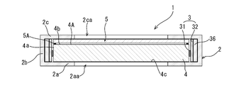
- the inspection illumination apparatus 1 includes a housing 2, four light source units 3, a light guide plate 4, and a light transmission plate 5, as shown in FIGS.
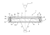
- the inspection illumination device 1 introduces light L1 emitted from the light source unit 3 from the end face portion 4a of the light guide plate 4 as shown in FIG.
- the article M is irradiated with the light L1, and the reflected light L2 from the article M passes through the light guide plate 4 (and the light transmission plate 5) and enters the camera C disposed thereabove to photograph the article M It is to inspect.
- the articles M are placed on a conveyor, a mounting table, or the like.
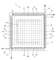
- FIG. 1 is a cross-sectional view taken along the line AA in FIG. In FIG.
- an upper wall 2 c to be described later of the housing 2 is drawn through. Further, in FIG. 2, the light guide plate 4 and the light transmission plate 5 are seen overlapping. Moreover, in FIG. 2, the light transmission board attachment member 5A mentioned later is abbreviate
- the housing 2 arranges and supports four light source units 3, a light guide plate 4 and a light transmission plate 5 inside.
- the housing 2 has a bottom wall 2a, a peripheral wall 2b connected to the bottom wall 2a, and an upper wall 2c connected to the peripheral wall 2b.
- the peripheral wall 2b has four sides, and the outer periphery of the housing 2 is square (see FIG. 2). Openings 2aa and 2ca are provided in the bottom wall 2a and the top wall 2c, respectively, to allow light to pass therethrough.
- the housing 2 is formed of a metal material such as aluminum or copper or a resin material. Although illustration is abbreviate
- the light guide plate 4 is rectangular in plan view (see FIG. 2) and has four end face portions 4a.
- One light source unit 3 is provided for each of the end surface portions 4a.
- the light source unit 3 includes a plurality of light emitting elements 31 as shown in FIG.
- the light emitting element 31 is mounted on an elongated printed circuit board 32 (see FIG. 2).
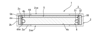
- the light emitting element 31 may be a surface mounted type LED (light emitting diode) as shown in FIGS. 1 and 2 or a shell type LED as shown in FIGS. 5 and 6.
- FIG. 5 is a cross-sectional view taken along a line AA in FIG.
- a predetermined number of the plurality of light emitting elements 31 are connected in series with the current limiting resistor 31A, and the series body is connected in parallel by a predetermined number of columns.
- the number of light emitting elements 31 is not particularly limited, and is determined according to the desired specification.
- One wiring cable 33 is provided for one light source unit 3 (see FIG. 2).
- the plus terminal 34 and the minus terminal 35 (see FIG. 4) of the light source unit 3 are connected to a dimming power supply (not shown) via the wiring cable 33.
- the light modulation control current for example, PWM current
- the light modulation power supply device is input to the plus terminal 34, the current flows through the plurality of light emitting elements 31, and the light modulation power supply device is It is output.
- PWM current for example, PWM current
- the light source unit 3 has only two terminals (plus terminal 34 and minus terminal 35), there is no mutual connection with the other light source units 3, and each light source unit 3 is independent, It is a simple structure. When one light source unit 3 breaks down, it is only necessary to replace only the light source unit 3 and maintenance is easy.
- the four light source units 3 are attached to the housing 2 independently.
- the method of attaching the light source unit 3 to the inside of the housing 2 is not particularly limited, but a heat conductive sheet 36 formed of silicone resin or the like is provided inside the housing 2, and the light source unit 3 is It is preferable to attach it so as to be pressed toward the light guide plate 4. Then, the light source unit 3 can be easily attached, and the heat generated by the light emitting element 31 can be efficiently conducted to the housing 2 by the heat conduction sheet 36 to dissipate heat.
- the color of light emitted by one light source unit 3 is one color. Therefore, in each light source unit 3, all the light emitting elements 31 mounted on one printed circuit board 32 emit the same color. Note that light includes infrared light and ultraviolet light as well as visible light, and one color (same color) means light whose wavelength can be regarded as substantially the same. Since one light source unit 3 emits only one color, light control can be simplified.
- the four light source units 3 can emit light of at least two or more colors in total.
- a plurality of light emitting elements 31 of one color for example, white
- a light emitting element 31 of one color for example, infrared color
- the dimming power supply device performs dimming control for each light source unit 3.
- a plurality of light emitting elements 31 of one color for example, white
- a plurality of light emitting elements 31 of one color for example, infrared color
- the dimming power supply device performs dimming control for each light source unit 3.
- a plurality of light emitting elements 31 of one color are mounted on one light source unit 3, and a plurality of light emitting elements 31 of one color (for example, green) are mounted on the other light source unit 3.
- a plurality of light emitting elements 31 of one color (for example, blue) are mounted on another light source unit 3 and a plurality of light emitting elements 31 of one color (for example, infrared color) are mounted on the other light source unit 3 .
- the dimming power supply device performs dimming control for each light source unit 3.
- the light guide plate 4 is a plate and is disposed inside the housing 2.
- a member having a predetermined refractive index and excellent in light guiding property is used, and a resin material such as transparent acrylic is applied.
- the light guide plate 4 is rectangular.
- the size and thickness of the light guide plate 4 are not particularly limited, but for example, one having a side length of about 10 to 20 cm and a thickness of about 5 mm can be used.
- the end face 4a of the light guide plate 4 is flat.
- storage holes 4aa for storing the light emitting element 31 are provided at constant intervals in the end face portion 4a of the light guide plate 4. It is also possible to flatten the end face portion 4 a of the light plate 4 (without providing the storage hole 4 aa) and bring the light emitting element 31 close to or in close contact therewith.
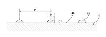
- the reflecting portion 4A can be a hemispherical and transparent hemispherical body in structure.
- the hemispherical shape refers to one in which the height decreases smoothly as it is away from the center of the surface (the center in plan view), and includes a semi-elliptical shape and the like.
- Transparent means something that is not colored, such as white.
- the semispherical reflective portion 4A can be formed by inkjet printing using an ultraviolet curing ink.
- the ultraviolet curing ink can be, for example, an acrylic resin-based transparent ink.
- the size of the reflecting portion 4A of the hemispherical body is not limited, but can be, for example, about 20 to 100 ⁇ m in diameter D and about 10 to 40 ⁇ m in height H.
- the interval (pitch) P of the reflecting portions 4A of the hemispherical body is determined according to the size of the reflecting portions 4A and the like, but can be, for example, about 100 to 300 ⁇ m.
- the size and interval P of the reflecting portion 4A of the hemispherical body may be changed according to the place.
- 4 A of reflection parts are not limited to a hemispherical body. As long as the light is well reflected, protrusions having various shapes or recesses (or grooves) as shown in Patent Document 1 may be used.
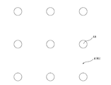
- the light L1 of the light emitting element 31 is incident to the inside of the light guide plate 4 from the end face portion 4a of the light guide plate 4.
- the light guide plate 4 can reflect toward the article M in order to irradiate the incident light to the article M placed below the lower surface 4 c by the plurality of reflecting portions 4A.
- the interface (the upper surface 4 b and the lower surface 4 c of the light guide plate 4) If the incident angle to the light is smaller than the critical angle (for example, 35 to 40 °), a part is transmitted and the rest is reflected, and as shown by the arrowed broken line in FIG.
- the light whose incident angle is larger than the critical angle repeats reflection to reach a wide range including the central portion of the light guide plate 4.
- the light entering the reflecting portion 4A is from the reflecting portion 4A to the outside as shown by the solid line with an arrow in FIG. 9 due to the difference in refractive index between the reflecting portion 4A and air.
- the incident angle to the interface is smaller than the critical angle (for example, 35 to 40 °)
- the critical angle for example, 35 to 40 °
- the surface of the reflective portion 4A is a curved surface, it travels to the article M from various directions.
- the reflected light L2 from the article M is incident from the lower surface 4c of the light guide plate 4, passes through the upper surface 4b or the reflecting portion 4A, and most of the light is emitted upward.
- the light transmitting plate 5 is disposed above the plurality of reflecting portions 4A with a gap.
- the light transmitting plate 5 is a member that transmits light well, and a resin material such as transparent acrylic is usually applied.
- the light transmission plate 5 is fixed in the housing 2 by being attached to the light guide plate 4 directly or in some cases to the housing 2 or the light source unit 3. This attachment is performed by the light transmission plate attachment member 5A, and the attachment member 5A uses a member (for example, double-sided tape or the like) of such a thickness as to make the gap. Since such a light transmitting plate 5 is disposed with a gap from the plurality of reflecting portions 4A, air exists in the gap, and protects the interface between the plurality of reflecting portions 4A and the light guide plate 4 and the air. Characteristics can be secured.
- the light transmitting plate 5 can be omitted or replaced by other means as long as it can protect the interface between the plurality of reflecting portions 4A and the air to ensure the characteristics.
- the camera C is provided with a light receiving element of CCD or CMOS, and converts a photographed image into digital data.
- the digital data is image processed by a computer and used to detect defects.
- the illumination device 1 for inspection of the present application irradiates light of a plurality of colors to the article M, enables inspection with light of a plurality of colors with a single camera, and reduces the price while lowering the cost. Inspection is possible. Furthermore, since each light source unit 3 emits light of one color and is independent, the structure is simple, the wiring etc. is simple, and each light source unit 3 can be maintained independently.
- the present invention can be carried out in the mode which added various improvement, correction, and modification based on the knowledge of those skilled in the art in the range which does not deviate from the main point It is.
- Inspection illumination device 2 Housing 2a: Lower wall 2b: Peripheral wall 2c: Upper wall 2aa, 2ca: Opening 3: Light source 31: Light emitting element 31A: Resistance 32: Printed circuit board 33: Wiring cable 34: Plus terminal 35 : Negative terminal 36: heat conductive sheet 4: light guide plate 4a: end face portion 4aa: accommodation hole 4b: upper surface 4c: lower surface 4A: reflection portion 5: light transmission plate 5A: member for light transmission plate attachment C: camera M: article
Landscapes
- Physics & Mathematics (AREA)
- General Physics & Mathematics (AREA)
- Optics & Photonics (AREA)
- Engineering & Computer Science (AREA)
- General Engineering & Computer Science (AREA)
- Analytical Chemistry (AREA)
- Life Sciences & Earth Sciences (AREA)
- Chemical & Material Sciences (AREA)
- Health & Medical Sciences (AREA)
- Biochemistry (AREA)
- General Health & Medical Sciences (AREA)
- Immunology (AREA)
- Pathology (AREA)
- Planar Illumination Modules (AREA)
- Investigating Materials By The Use Of Optical Means Adapted For Particular Applications (AREA)
- Investigating Or Analysing Materials By Optical Means (AREA)
Abstract
Description
2:ハウジング
2a:下壁
2b:周壁
2c:上壁
2aa、2ca:開口部
3:光源部
31:発光素子
31A:抵抗
32:プリント基板
33:配線ケーブル
34:プラス端子
35:マイナス端子
36:熱伝導シート
4:導光板
4a:端面部
4aa:収納穴
4b:上面
4c:下面
4A:反射部
5:光透過板
5A:光透過板取り付け用の部材
C:カメラ
M:物品
Claims (2)
- ハウジングと、
前記ハウジング内に配置された4つの光源部と、
前記光源部で発光された光を導き、4つの端面部を有する導光板と、
前記導光板の上面に形成されており、導光板の下面に向けて光を反射させる反射部と、
を備え、
前記光源部の各々は、前記端面部ごとに設けられ、1つの色の光を発光可能であって独立に調光制御され、
前記4つの光源部は、全体で少なくとも2つ以上の色の光を発光可能であることを特徴とする検査用照明装置。 - 請求項1に記載の検査用照明装置において、
前記光源部の各々は、相互の結線がなく、独立に前記ハウジング内に取り付けられていることを特徴とする検査用照明装置。
Priority Applications (7)
| Application Number | Priority Date | Filing Date | Title |
|---|---|---|---|
| KR1020197033858A KR20190139285A (ko) | 2017-12-04 | 2018-11-30 | 검사용 조명 장치 |
| KR1020227044573A KR20230003414A (ko) | 2017-12-04 | 2018-11-30 | 검사용 조명 장치 |
| CN201880035465.7A CN110691967A (zh) | 2017-12-04 | 2018-11-30 | 检查用照明装置 |
| KR1020217021520A KR20210089793A (ko) | 2017-12-04 | 2018-11-30 | 검사용 조명 장치 |
| US16/626,080 US11105488B2 (en) | 2017-12-04 | 2018-11-30 | Lighting device for inspection |
| JP2019558188A JP6775264B2 (ja) | 2017-12-04 | 2018-11-30 | 検査用照明装置 |
| EP18885909.4A EP3722791A4 (en) | 2017-12-04 | 2018-11-30 | LIGHTING DEVICE FOR INSPECTION |
Applications Claiming Priority (2)
| Application Number | Priority Date | Filing Date | Title |
|---|---|---|---|
| JP2017232960 | 2017-12-04 | ||
| JP2017-232960 | 2017-12-04 |
Publications (1)
| Publication Number | Publication Date |
|---|---|
| WO2019111821A1 true WO2019111821A1 (ja) | 2019-06-13 |
Family
ID=66751491
Family Applications (1)
| Application Number | Title | Priority Date | Filing Date |
|---|---|---|---|
| PCT/JP2018/044235 Ceased WO2019111821A1 (ja) | 2017-12-04 | 2018-11-30 | 検査用照明装置 |
Country Status (6)
| Country | Link |
|---|---|
| US (1) | US11105488B2 (ja) |
| EP (1) | EP3722791A4 (ja) |
| JP (1) | JP6775264B2 (ja) |
| KR (3) | KR20230003414A (ja) |
| CN (1) | CN110691967A (ja) |
| WO (1) | WO2019111821A1 (ja) |
Cited By (4)
| Publication number | Priority date | Publication date | Assignee | Title |
|---|---|---|---|---|
| JP2021085808A (ja) * | 2019-11-29 | 2021-06-03 | シーシーエス株式会社 | 光照射装置 |
| JP2021148726A (ja) * | 2020-03-23 | 2021-09-27 | 東京エレクトロン株式会社 | 光源、分光分析システム及び分光分析方法 |
| JP2023085027A (ja) * | 2021-12-08 | 2023-06-20 | シーシーエス株式会社 | 検査用光照射装置、及び、検査システム |
| WO2026042500A1 (ja) * | 2024-08-20 | 2026-02-26 | シーシーエス株式会社 | 検査用光照射装置、表面形状解析システム |
Families Citing this family (2)
| Publication number | Priority date | Publication date | Assignee | Title |
|---|---|---|---|---|
| KR102845713B1 (ko) * | 2020-06-11 | 2025-08-13 | 현대자동차주식회사 | 순차점등 조명 시스템 및 그 제어 방법 |
| KR102744196B1 (ko) * | 2024-08-02 | 2024-12-18 | 주식회사 제이디 | 광택을 가진 표면 검사 및 측정 방법 |
Citations (6)
| Publication number | Priority date | Publication date | Assignee | Title |
|---|---|---|---|---|
| JPH10319877A (ja) * | 1997-05-16 | 1998-12-04 | Toshiba Corp | 画像表示装置及び発光装置 |
| JPH1164639A (ja) * | 1997-08-13 | 1999-03-05 | Seiko Epson Corp | 照明装置、液晶装置及び電子機器 |
| JP2003139712A (ja) * | 2001-10-31 | 2003-05-14 | Ccs Inc | Led照明装置 |
| JP2013254711A (ja) * | 2012-06-08 | 2013-12-19 | Bando Chemical Industries Ltd | 面発光装置 |
| JP2016085171A (ja) * | 2014-10-28 | 2016-05-19 | コニカミノルタ株式会社 | アレイ物検査用照明装置、アレイ物検査装置およびアレイ物検査用導光板 |
| JP2016136124A (ja) | 2015-01-24 | 2016-07-28 | 株式会社イマック | 検査用照明装置 |
Family Cites Families (21)
| Publication number | Priority date | Publication date | Assignee | Title |
|---|---|---|---|---|
| JP2000021206A (ja) * | 1998-07-02 | 2000-01-21 | Ccs Kk | 照明装置 |
| CN1384352A (zh) * | 2001-04-30 | 2002-12-11 | 瀚宇彩晶股份有限公司 | 多颜色光源异物检查装置 |
| JP2002350846A (ja) | 2001-05-22 | 2002-12-04 | Yazaki Corp | Ledバックライト |
| US20050117145A1 (en) * | 2003-11-28 | 2005-06-02 | Joshua Altman | Detection of imperfections in precious stones |
| US20060132383A1 (en) * | 2004-09-27 | 2006-06-22 | Idc, Llc | System and method for illuminating interferometric modulator display |
| CN101248348B (zh) * | 2005-08-26 | 2012-05-30 | Ccs株式会社 | 光照射装置和光学构件 |
| US20070097066A1 (en) | 2005-10-27 | 2007-05-03 | Ward Calvin B | LCD display utilizing light emitters with variable light output |
| CN101393137B (zh) * | 2008-10-24 | 2011-02-02 | 胡伟 | 一种产品外观质量检测系统及产品外观质量检测设备 |
| CN101793363A (zh) * | 2010-04-20 | 2010-08-04 | 威海华菱光电有限公司 | 一种照明装置 |
| CN101846255A (zh) * | 2010-05-12 | 2010-09-29 | 威海华菱光电有限公司 | 一种照明装置光源 |
| JP2012026862A (ja) * | 2010-07-23 | 2012-02-09 | Konica Minolta Business Technologies Inc | 表面検査装置、表面検査方法 |
| DE102011104214A1 (de) * | 2011-06-15 | 2012-12-20 | Osram Opto Semiconductors Gmbh | Flächenleuchte mit veränderbarer Lichtfarbe |
| CN102691918A (zh) * | 2012-06-15 | 2012-09-26 | 昆山翰辉电子科技有限公司 | 有色平面led灯 |
| WO2014055962A1 (en) * | 2012-10-05 | 2014-04-10 | Seagate Technology Llc | Imaging a transparent article |
| JP2016161812A (ja) * | 2015-03-03 | 2016-09-05 | パナソニックIpマネジメント株式会社 | 映像表示装置 |
| DE102015212910A1 (de) * | 2015-07-09 | 2017-01-12 | Sac Sirius Advanced Cybernetics Gmbh | Vorrichtung zur Beleuchtung von Gegenständen |
| CN205664193U (zh) | 2016-03-25 | 2016-10-26 | 安徽泽润光电有限公司 | Led面板灯 |
| CN205535130U (zh) | 2016-04-05 | 2016-08-31 | 苏州百仕照明有限公司 | 一种安装拆卸简便的led平板灯 |
| CN106532431A (zh) * | 2016-12-28 | 2017-03-22 | 尚华 | 一种应用于人体内的激光发生光导入装置 |
| WO2019035830A1 (en) * | 2017-08-16 | 2019-02-21 | Ecosense Lighting Inc | MULTI-CHANNEL WHITE LIGHT DEVICE FOR HIGH-COLOR RENDERABLE WHITE LED ACCORDING LIGHT DELIVERY |
| US10481097B1 (en) * | 2018-10-01 | 2019-11-19 | Guardian Glass, LLC | Method and system for detecting inclusions in float glass based on spectral reflectance analysis |
-
2018
- 2018-11-30 KR KR1020227044573A patent/KR20230003414A/ko not_active Ceased
- 2018-11-30 US US16/626,080 patent/US11105488B2/en active Active
- 2018-11-30 EP EP18885909.4A patent/EP3722791A4/en not_active Ceased
- 2018-11-30 WO PCT/JP2018/044235 patent/WO2019111821A1/ja not_active Ceased
- 2018-11-30 JP JP2019558188A patent/JP6775264B2/ja active Active
- 2018-11-30 KR KR1020197033858A patent/KR20190139285A/ko not_active Ceased
- 2018-11-30 CN CN201880035465.7A patent/CN110691967A/zh active Pending
- 2018-11-30 KR KR1020217021520A patent/KR20210089793A/ko not_active Ceased
Patent Citations (6)
| Publication number | Priority date | Publication date | Assignee | Title |
|---|---|---|---|---|
| JPH10319877A (ja) * | 1997-05-16 | 1998-12-04 | Toshiba Corp | 画像表示装置及び発光装置 |
| JPH1164639A (ja) * | 1997-08-13 | 1999-03-05 | Seiko Epson Corp | 照明装置、液晶装置及び電子機器 |
| JP2003139712A (ja) * | 2001-10-31 | 2003-05-14 | Ccs Inc | Led照明装置 |
| JP2013254711A (ja) * | 2012-06-08 | 2013-12-19 | Bando Chemical Industries Ltd | 面発光装置 |
| JP2016085171A (ja) * | 2014-10-28 | 2016-05-19 | コニカミノルタ株式会社 | アレイ物検査用照明装置、アレイ物検査装置およびアレイ物検査用導光板 |
| JP2016136124A (ja) | 2015-01-24 | 2016-07-28 | 株式会社イマック | 検査用照明装置 |
Non-Patent Citations (1)
| Title |
|---|
| See also references of EP3722791A4 |
Cited By (6)
| Publication number | Priority date | Publication date | Assignee | Title |
|---|---|---|---|---|
| JP2021085808A (ja) * | 2019-11-29 | 2021-06-03 | シーシーエス株式会社 | 光照射装置 |
| JP2021148726A (ja) * | 2020-03-23 | 2021-09-27 | 東京エレクトロン株式会社 | 光源、分光分析システム及び分光分析方法 |
| JP7562277B2 (ja) | 2020-03-23 | 2024-10-07 | 東京エレクトロン株式会社 | 分光分析システム及び分光分析方法 |
| JP2023085027A (ja) * | 2021-12-08 | 2023-06-20 | シーシーエス株式会社 | 検査用光照射装置、及び、検査システム |
| JP7807220B2 (ja) | 2021-12-08 | 2026-01-27 | シーシーエス株式会社 | 検査用光照射装置、及び、検査システム |
| WO2026042500A1 (ja) * | 2024-08-20 | 2026-02-26 | シーシーエス株式会社 | 検査用光照射装置、表面形状解析システム |
Also Published As
| Publication number | Publication date |
|---|---|
| JP6775264B2 (ja) | 2020-10-28 |
| EP3722791A1 (en) | 2020-10-14 |
| JPWO2019111821A1 (ja) | 2020-10-08 |
| KR20230003414A (ko) | 2023-01-05 |
| EP3722791A4 (en) | 2021-07-07 |
| US20200208805A1 (en) | 2020-07-02 |
| CN110691967A (zh) | 2020-01-14 |
| KR20190139285A (ko) | 2019-12-17 |
| KR20210089793A (ko) | 2021-07-16 |
| US11105488B2 (en) | 2021-08-31 |
Similar Documents
| Publication | Publication Date | Title |
|---|---|---|
| WO2019111821A1 (ja) | 検査用照明装置 | |
| EP2389536B1 (en) | Light emitting diode linear light for machine vision | |
| JP6042402B2 (ja) | 照明モジュール及びこれを用いる外観検査システム | |
| TW402856B (en) | LED illuminator | |
| JPH11312898A (ja) | 電子部品実装装置 | |
| US8714455B2 (en) | External illumination apparatus for optical information reading apparatus | |
| JP2012064551A (ja) | Ledを使った外部照明ユニット | |
| CN101390451A (zh) | Led照明设备 | |
| JPH11295047A (ja) | 照明装置 | |
| WO2022071161A1 (ja) | 光源装置及び導光アレイ部 | |
| JP4659155B2 (ja) | 目視検査用ライト | |
| CN105180032B (zh) | 一种照明灯具及照明灯具组合 | |
| JP5004360B2 (ja) | 検査用照明装置 | |
| JP2017107821A (ja) | 照明器具 | |
| TWI426247B (zh) | 光源測量方法 | |
| JP7046511B2 (ja) | 同軸落射照明装置 | |
| KR101071727B1 (ko) | 조명장치 | |
| JP7515107B2 (ja) | 照明器具 | |
| KR101790050B1 (ko) | 발광소자 어레이 | |
| JP5578329B2 (ja) | ライン光源 | |
| KR20050121403A (ko) | 백라이트 조명 기구 및 이를 이용한 검사 장치 | |
| JP2012064179A (ja) | 光学情報読取装置用のled照明装置 | |
| KR20110008116A (ko) | 광섬유와 발광다이오드 기반 장식타일 | |
| JP2002373517A (ja) | 照明装置 | |
| JP6193053B2 (ja) | Led照明装置 |
Legal Events
| Date | Code | Title | Description |
|---|---|---|---|
| 121 | Ep: the epo has been informed by wipo that ep was designated in this application |
Ref document number: 18885909 Country of ref document: EP Kind code of ref document: A1 |
|
| ENP | Entry into the national phase |
Ref document number: 20197033858 Country of ref document: KR Kind code of ref document: A |
|
| ENP | Entry into the national phase |
Ref document number: 2019558188 Country of ref document: JP Kind code of ref document: A |
|
| NENP | Non-entry into the national phase |
Ref country code: DE |
|
| ENP | Entry into the national phase |
Ref document number: 2018885909 Country of ref document: EP Effective date: 20200706 |
|
| WWP | Wipo information: published in national office |
Ref document number: 2018885909 Country of ref document: EP |
|
| WWW | Wipo information: withdrawn in national office |
Ref document number: 2018885909 Country of ref document: EP |