WO2019116442A1 - 部品供給装置及び、部品供給方法 - Google Patents
部品供給装置及び、部品供給方法 Download PDFInfo
- Publication number
- WO2019116442A1 WO2019116442A1 PCT/JP2017/044519 JP2017044519W WO2019116442A1 WO 2019116442 A1 WO2019116442 A1 WO 2019116442A1 JP 2017044519 W JP2017044519 W JP 2017044519W WO 2019116442 A1 WO2019116442 A1 WO 2019116442A1
- Authority
- WO
- WIPO (PCT)
- Prior art keywords
- component
- parts
- lead
- stage
- components
- Prior art date
- Legal status (The legal status is an assumption and is not a legal conclusion. Google has not performed a legal analysis and makes no representation as to the accuracy of the status listed.)
- Ceased
Links
Images





Classifications
-
- H—ELECTRICITY
- H05—ELECTRIC TECHNIQUES NOT OTHERWISE PROVIDED FOR
- H05K—PRINTED CIRCUITS; CASINGS OR CONSTRUCTIONAL DETAILS OF ELECTRIC APPARATUS; MANUFACTURE OF ASSEMBLAGES OF ELECTRICAL COMPONENTS
- H05K13/00—Apparatus or processes specially adapted for manufacturing or adjusting assemblages of electric components
- H05K13/08—Monitoring manufacture of assemblages
- H05K13/086—Supply management, e.g. supply of components or of substrates
-
- B—PERFORMING OPERATIONS; TRANSPORTING
- B65—CONVEYING; PACKING; STORING; HANDLING THIN OR FILAMENTARY MATERIAL
- B65G—TRANSPORT OR STORAGE DEVICES, e.g. CONVEYORS FOR LOADING OR TIPPING, SHOP CONVEYOR SYSTEMS OR PNEUMATIC TUBE CONVEYORS
- B65G47/00—Article or material-handling devices associated with conveyors; Methods employing such devices
- B65G47/02—Devices for feeding articles or materials to conveyors
- B65G47/04—Devices for feeding articles or materials to conveyors for feeding articles
- B65G47/12—Devices for feeding articles or materials to conveyors for feeding articles from disorderly-arranged article piles or from loose assemblages of articles
- B65G47/14—Devices for feeding articles or materials to conveyors for feeding articles from disorderly-arranged article piles or from loose assemblages of articles arranging or orientating the articles by mechanical or pneumatic means during feeding
- B65G47/1492—Devices for feeding articles or materials to conveyors for feeding articles from disorderly-arranged article piles or from loose assemblages of articles arranging or orientating the articles by mechanical or pneumatic means during feeding the articles being fed from a feeding conveyor
-
- B—PERFORMING OPERATIONS; TRANSPORTING
- B65—CONVEYING; PACKING; STORING; HANDLING THIN OR FILAMENTARY MATERIAL
- B65G—TRANSPORT OR STORAGE DEVICES, e.g. CONVEYORS FOR LOADING OR TIPPING, SHOP CONVEYOR SYSTEMS OR PNEUMATIC TUBE CONVEYORS
- B65G47/00—Article or material-handling devices associated with conveyors; Methods employing such devices
- B65G47/74—Feeding, transfer, or discharging devices of particular kinds or types
- B65G47/90—Devices for picking-up and depositing articles or materials
- B65G47/91—Devices for picking-up and depositing articles or materials incorporating pneumatic, e.g. suction, grippers
- B65G47/912—Devices for picking-up and depositing articles or materials incorporating pneumatic, e.g. suction, grippers provided with drive systems with rectilinear movements only
-
- H—ELECTRICITY
- H05—ELECTRIC TECHNIQUES NOT OTHERWISE PROVIDED FOR
- H05K—PRINTED CIRCUITS; CASINGS OR CONSTRUCTIONAL DETAILS OF ELECTRIC APPARATUS; MANUFACTURE OF ASSEMBLAGES OF ELECTRICAL COMPONENTS
- H05K13/00—Apparatus or processes specially adapted for manufacturing or adjusting assemblages of electric components
- H05K13/02—Feeding of components
- H05K13/028—Simultaneously loading a plurality of loose objects, e.g. by means of vibrations, pressure differences, magnetic fields
-
- H—ELECTRICITY
- H05—ELECTRIC TECHNIQUES NOT OTHERWISE PROVIDED FOR
- H05K—PRINTED CIRCUITS; CASINGS OR CONSTRUCTIONAL DETAILS OF ELECTRIC APPARATUS; MANUFACTURE OF ASSEMBLAGES OF ELECTRICAL COMPONENTS
- H05K13/00—Apparatus or processes specially adapted for manufacturing or adjusting assemblages of electric components
- H05K13/04—Mounting of components, e.g. of leadless components
- H05K13/043—Feeding one by one by other means than belts
Definitions
- the present invention relates to a parts supply apparatus and the like including a replenishment apparatus for replenishing parts and a stage in which parts replenished from the replenishment apparatus are scattered.
- Some component supply apparatuses supply components in a state of being scattered on a stage, as described in the following patent documents.
- the present specification describes a plurality of replenishment devices for replenishing components of different shapes, a plurality of stages in which the components to be replenished from the replenishment device are interspersed, and the plurality of replenishments. And a control unit for supplying the components at any timing from each of the devices to the stage.
- the present specification describes a component mounting apparatus in which components of different shapes supplied to each of a plurality of stages from each of a plurality of replenishment devices are scattered in each of the plurality of stages.
- a component supply method which is capable of changing the amount of components for each of the plurality of stages.
- components can be replenished from any of the plurality of replenishment devices to the stage at any timing.
- the amount of parts to be replenished from the replenishment device that replenishes the stages can be changed.
- FIG. 6 shows the conveyor belt with the lead parts of small dimensions entering between two adjacent protrusions.
- FIG. 5 is a view showing the conveyor belt in a state in which large-sized lead parts are inserted between two adjacent protrusions.
- FIG. 1 shows a component mounter 10.
- the component mounter 10 is a device for performing the mounting operation of components on the circuit substrate 12.
- the component mounter 10 includes an apparatus main body 20, a base material conveyance / holding device 22, a component mounting device 24, imaging devices 26, 28, a component supply device 30, a bulk component supply device 32, and a control device 34 (see FIG. 11).
- a circuit board, a base material of a three-dimensional structure, etc. are mentioned as circuit base material 12
- a printed wiring board, a printed circuit board, etc. are mentioned as a circuit board.
- the apparatus body 20 is constituted by a frame portion 40 and a beam portion 42 mounted on the frame portion 40.
- the base material transport and holding device 22 is disposed at the center of the frame portion 40 in the front-rear direction, and includes a transport device 50 and a clamp device 52.
- the transfer device 50 is a device for transferring the circuit substrate 12
- the clamp device 52 is a device for holding the circuit substrate 12.
- the base material transport and holding device 22 transports the circuit base material 12 and holds the circuit base material 12 fixedly at a predetermined position.
- the transport direction of the circuit substrate 12 is referred to as the X direction
- the horizontal direction perpendicular to the direction is referred to as the Y direction
- the vertical direction is referred to as the Z direction. That is, the width direction of the component mounter 10 is the X direction, and the front-rear direction is the Y direction.
- the component mounting device 24 is disposed in the beam unit 42 and has two working heads 60 and 62 and a working head moving device 64.
- Each work head 60, 62 has a suction nozzle (see FIG. 2) 66, and holds the components by the suction nozzle 66.
- the working head moving device 64 has an X direction moving device 68, a Y direction moving device 70, and a Z direction moving device 72.
- the two working heads 60 and 62 are integrally moved to an arbitrary position on the frame portion 40 by the X-direction moving device 68 and the Y-direction moving device 70. Further, as shown in FIG.
- the working heads 60 and 62 are detachably mounted on the sliders 74 and 76, and the Z-direction moving device 72 moves the sliders 74 and 76 individually in the vertical direction. In other words, the work heads 60 and 62 are individually moved in the vertical direction by the Z-direction moving device 72.
- the imaging device 26 is attached to the slider 74 in a state of facing downward, and is moved together with the working head 60 in the X direction, the Y direction, and the Z direction. Thereby, the imaging device 26 captures an arbitrary position on the frame unit 40. As shown in FIG. 1, the imaging device 28 is disposed between the base material conveyance and holding device 22 on the frame portion 40 and the component supply device 30 so as to face upward. Thereby, the imaging device 28 images the component held by the suction nozzle 66 of the working heads 60 and 62.
- the component supply device 30 is disposed at one end of the frame portion 40 in the front-rear direction.
- the component supply device 30 has a tray-type component supply device 78 and a feeder-type component supply device (not shown).
- the tray-type component supply device 78 is a device that supplies components in a state of being placed on the tray.
- the feeder type component supply device is a device that supplies components by a tape feeder (not shown) and a stick feeder (not shown).
- the bulk parts supply device 32 is disposed at the other end of the frame portion 40 in the front-rear direction.
- the loose parts feeder 32 is a device for aligning a plurality of parts scattered in a scattered state and supplying the parts in an aligned state. That is, it is an apparatus which aligns a plurality of parts of an arbitrary posture to a predetermined posture and supplies the components of the predetermined posture.
- the configuration of the component supply device 32 will be described in detail below.
- the parts supplied by the parts supply device 30 and the bulk parts supply device 32 roughly different types of parts, specifically, for example, electronic circuit parts, components of a solar cell, components of a power module, etc. It can be mentioned. Further, there are electronic circuit parts including parts having leads, parts not having leads, and the like.
- the bulk parts supply device 32 has a main body 80, a parts supply unit 82, an imaging device 84, and a parts delivery device 86.
- the component supply unit 82 includes a component supply device 88, a component interspersing device 90 (see FIG. 4), and a component return device 92 (see FIG. 4). And the component return device 92 are integrally configured.
- the component supply unit 82 is detachably assembled to the base 96 of the main body 80. In the bulk component supply device 32, five component supply units 82 are arranged in a line in the X direction.
- the parts feeder 88 is generally in the form of a rectangular box, and extends in the Y direction as shown in FIGS. 4 and 5. Note that the Y direction is described as the front-rear direction of the component feeder 88, the direction toward the side on which the component return device 92 is disposed in the component supply unit 82 is described as the front, and the component supplier 88 is disposed. The direction toward the side that is being used is referred to as the rear.
- the component feeder 88 is open at the top surface and the front surface, the opening at the top surface is the inlet 97 for the component, and the opening at the front surface is the outlet 98 for the component.
- the inclined plate 104 is disposed below the insertion port 97. The inclined plate 104 is disposed so as to incline downward from the end face on the rear side of the component feeder 88 toward the central direction.
- a conveyor device 106 is disposed on the front side of the inclined plate 104.
- the conveyor device 106 is disposed to be inclined upward from the front end of the inclined plate 104 toward the front of the component feeder 88.
- the conveyor belt 112 of the conveyor device 106 rotates counterclockwise in FIG. That is, the conveyance direction by the conveyor device 106 is obliquely upward from the front end of the inclined plate 104 toward the front.
- a plurality of protrusions 115 are formed on the surface of the conveyor belt 112, that is, on the conveyance surface so as to extend in the width direction of the conveyor belt 112.
- the plurality of protrusions 115 are formed at regular intervals in the rotational direction of the conveyor belt 112, and the spacing is longer than the dimension in the longitudinal direction of the components supplied by the component feeder 88.
- an inclined plate 126 is disposed below the front end of the conveyor device 106.
- the inclined plate 126 is disposed from the end surface on the front side of the component feeder 88 toward the lower side of the conveyor device 106, and the end on the rear side is inclined obliquely downward.
- the inclined plate 128 is disposed below the inclined plate 126. The inclined plate 128 is inclined from the lower side of the central portion of the conveyor device 106 toward the discharge port 98 of the component feeder 88 so that the front end is positioned downward.
- a pair of side frame portions 130 is assembled to the base 96.
- the pair of side frame portions 130 are erected so as to extend in parallel with each other and in the Y direction in the opposite state.
- the distance between the pair of side frame portions 130 is slightly larger than the dimension in the width direction of the component feeder 88, and the component feeder 88 can be detachably attached between the pair of side frame portions 130. It is attached to.
- the part interspersing device 90 includes a part support member 150 and a part support member moving device 152.
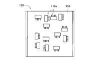
- the component support member 150 is configured of a stage 156 and a pair of side wall portions 158.
- the stage 156 has a generally elongated plate shape, and is disposed so as to extend from the lower side to the front side of the parts feeder 88 mounted between the pair of side frame portions 130.
- the upper surface of the stage 156 is generally horizontal, and as shown in FIG. 5, is disposed with a slight clearance from the front end of the inclined plate 128 of the component feeder 88.
- the pair of side wall portions 158 is fixed in a state of being erected on both sides in the longitudinal direction of the stage 156, and the upper end of each side wall portion 158 is from the upper surface of the stage 156 It extends upward.
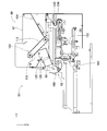
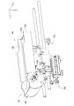
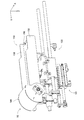
- the component support member moving device 152 slides the component support member 150 in the Y direction by the operation of the air cylinder (see FIG. 11) 166. At this time, the component support member 150 moves between a stored state (see FIG. 6) stored under the component feeder 88 and an exposed state exposed from below the component feeder 88 (see FIG. 5). .
- the component return device 92 includes a component storage container 180 and a container swing device 181, as shown in FIG.
- the component storage container 180 generally has a box shape, and the bottom surface has an arc shape.
- the component storage container 180 is pivotally held at the front end of the stage 156 of the component support member 150, and is pivoted by the operation of the container swing device 181. At this time, the component storage container 180 swings between a storage orientation (see FIG. 7) with the opening directed upward and a return orientation (see FIG. 8) with the opening directed to the upper surface of the stage 156 of the component support member 150.
- a storage orientation see FIG. 7
- a return orientation see FIG. 8
- the imaging device 84 includes a camera 290 and a camera moving device 292, as shown in FIG.
- the camera moving device 292 includes a guide rail 296 and a slider 298.
- the guide rail 296 is fixed to the main body 80 so as to extend in the width direction (X direction) of the bulk component feeder 32 above the component feeder 88.
- the slider 298 is slidably attached to the guide rail 296, and slides to an arbitrary position by the operation of an electromagnetic motor (see FIG. 11) 299.
- the camera 290 is mounted on the slider 298 in a state of facing downward.
- the parts delivery device 86 includes a parts holding head moving device 300, a parts holding head 302, and two shuttle devices 304, as shown in FIG.
- the component holding head moving device 300 includes an X direction moving device 310, a Y direction moving device 312, and a Z direction moving device 314.
- the Y-direction moving device 312 has a Y-slider 316 disposed above the component supply unit 82 so as to extend in the X-direction, and the Y-slider 316 is driven by an electromagnetic motor (see FIG. 11) 319. Move to any position in the Y direction.
- the X-direction moving device 310 has an X-slider 320 disposed on the side surface of the Y-slider 316, and the X-slider 320 is moved to an arbitrary position in the X-direction by driving an electromagnetic motor (see FIG. 11) 321. Moving.
- the Z-direction moving device 314 has a Z-slider 322 disposed on the side surface of the X-slider 320, and the Z-slider 322 is positioned at an arbitrary position in the Z-direction by driving an electromagnetic motor (see FIG. 11). Moving.
- the component holding head 302 includes a head main body 330, a suction nozzle 332, a nozzle rotation device 334, and a nozzle rotation device 335, as shown in FIG.
- the head body 330 is integrally formed with the Z-slider 322.
- the suction nozzle 332 holds components, and is detachably mounted to the lower end of the holder 340.
- the holder 340 is bendable at the support shaft 344, and the operation of the nozzle turning device 334 causes the holder 340 to bend upward by 90 degrees.
- the suction nozzle 332 mounted at the lower end of the holder 340 turns 90 degrees and is positioned at the turning position.
- the suction nozzle 332 is pivoted between the non-orbiting position and the pivoting position by the operation of the nozzle pivoting device 334.
- the nozzle rotation device 335 also rotates the suction nozzle 332 about its axis.
- each of the two shuttle devices 304 includes a component carrier 388 and a component carrier moving device 390 as shown in FIG. 3 and is fixed to the main body 80 side by side on the front side of the component supply unit 82. It is done.
- Five component receiving members 392 are mounted on the component carrier 388 in a line in the lateral direction, and the components are mounted on the respective component receiving members 392.
- the loose parts supply device 32 can supply various parts, and various parts receiving members 392 are prepared according to the shape of the parts.
- various parts receiving members 392 are prepared according to the shape of the parts.
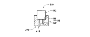
- an electronic circuit component supplied by the bulk component supply device 32 as shown in FIG. 10, a component receiving member 392 corresponding to the lead component 410 having a lead will be described.
- the lead component 410 is composed of a block-shaped component body 412 and two leads 414 projecting from the bottom surface of the component body 412.
- a component receiving recess 416 having a shape corresponding to the lead component 410 is formed in the component receiving member 392.
- the component receiving recess 416 is a stepped recess, and includes a main portion receiving recess 418 opening on the top surface of the component receiving member 392 and a lead receiving recess 420 opening on the bottom surface of the main portion receiving recess 418 There is. Then, the lead part 410 is inserted into the inside of the part receiving recess 416 with the lead 414 directed downward. Thus, the lead component 410 is placed inside the component receiving recess 416 in a state where the lead 414 is inserted into the lead receiving recess 420 and the component body 412 is inserted into the main body receiving recess 418.
- the component carrier moving device 390 is a plate-like longitudinal member, and is disposed on the front side of the component supply unit 82 so as to extend in the front-rear direction.
- a component carrier 388 is slidably provided in the front-rear direction on the top surface of the component carrier moving device 390, and slides to an arbitrary position in the front-rear direction by driving of an electromagnetic motor (see FIG. 11) 430.
- the component carrier 388 slides in a direction approaching the component supply unit 82
- the component carrier 388 slides to the component receiving position positioned within the moving range of the component holding head 302 by the component holding head moving device 300.
- the component carrier 388 slides in the direction away from the component supply unit 82
- the component carrier 388 slides to the component supply position located within the movement range of the working heads 60, 62 by the working head moving device 64.
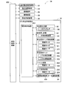
- the control device 34 includes a general control device 450, a plurality of individual control devices (only one is shown in the drawing) 452, and an image processing device 454.
- the general control unit 450 is mainly composed of a computer, and is connected to the base material conveyance and holding unit 22, the component mounting unit 24, the imaging unit 26, the imaging unit 28, the component supply unit 30, and the bulk component supply unit 32. ing.
- the general control device 450 controls the base material conveyance and holding device 22, the component mounting device 24, the imaging device 26, the imaging device 28, the component supply device 30, and the bulk component supply device 32 in an integrated manner.
- the plurality of individual control devices 452 are mainly composed of a computer, and are used for the base material conveyance and holding device 22, the component mounting device 24, the imaging device 26, the imaging device 28, the component supply device 30, and the bulk component supply device 32. It is provided correspondingly (in the figure, only the individual control device 452 corresponding to the bulk component supply device 32 is shown).
- the individual control device 452 of the bulk component supply device 32 is connected to the component interspersing device 90, the component returning device 92, the camera moving device 292, the component holding head moving device 300, the component holding head 302, and the shuttle device 304. Thereby, the individual control device 452 of the bulk component supply device 32 controls the component interspersing device 90, the component returning device 92, the camera moving device 292, the component holding head moving device 300, the component holding head 302, and the shuttle device 304.
- the image processing device 454 is connected to the imaging device 84 and processes imaging data captured by the imaging device 84.
- the image processing device 454 is connected to the individual control device 452 of the bulk component supply device 32. Thereby, the individual control device 452 of the bulk component supply device 32 acquires imaging data imaged by the imaging device 84.
- the component mounter 10 mounts components on the circuit substrate 12 held by the substrate conveyance and holding device 22 according to the above-described configuration. Specifically, the circuit substrate 12 is conveyed to the working position, and is held fixed by the clamp device 52 at that position. Next, the imaging device 26 moves above the circuit substrate 12 and images the circuit substrate 12. Thereby, information on the error of the holding position of the circuit substrate 12 can be obtained. Further, the component supply device 30 or the bulk component supply device 32 supplies components at a predetermined supply position. The supply of parts by the bulk parts supply device 32 will be described in detail later. Then, either of the working heads 60 and 62 moves above the supply position of the parts, and the suction nozzle 66 holds the parts.
- the working heads 60 and 62 holding the components move to the upper side of the imaging device 28, and the components held by the suction nozzle 66 are imaged by the imaging device 28. This provides information on the error in the holding position of the part. Then, the working heads 60 and 62 holding the components move above the circuit substrate 12 and correct the holding position error of the circuit substrate 12, the holding position error of the components, etc. , And mounted on the circuit substrate 12.
- the worker inserts the lead component 410 from the inlet 97 on the top surface of the component feeder 88.
- the component support member 150 is moved to the lower side of the component feeder 88 by the operation of the component support member moving device 152, and is in the stored state (see FIG. 6).
- the component storage container 180 disposed at the front end of the component support member 150 is located in front of the component feeder 88, A posture (accommodating posture) in which the opening of the storage container 180 is directed upward.
- the lead component 410 loaded from the inlet 97 of the component feeder 88 falls onto the inclined plate 104 of the component feeder 88 and rolls down to the lower end on the front side of the inclined plate 104. At this time, the lead component 410 rolled down to the lower end on the front side of the inclined plate 104 is piled up between the lower end on the front side of the inclined plate 104 and the lower end on the rear side of the conveyor device 106. Then, when the conveyor device 106 is operated, the conveyor belt 112 of the conveyor device 106 orbits counterclockwise in FIG.
- the lead parts 410 transported by the conveyor belt 112 fall onto the inclined plate 126 from the upper end on the front side of the conveyor device 106.
- the lead parts 410 dropped onto the inclined plate 126 roll back on the inclined plate 126 and fall onto the inclined plate 128.
- the lead component 410 dropped onto the inclined plate 128 rolls down toward the front and is discharged from the outlet 98 on the front side of the component feeder 88.
- the lead component 410 discharged from the discharge port 98 of the component feeder 88 is accommodated inside the component container 180. Then, when the lead component 410 of a predetermined amount is discharged from the component supply device 88, that is, when the conveyor device 106 operates a predetermined amount, the conveyor device 106 is stopped. Next, the component support member 150 is moved forward from the stored state by the operation of the component support member moving device 152.
- the container swinging device 181 of the component returning device 92 operates to swing the component storage container 180.
- the posture of the component storage container 180 vigorously changes from the posture in which the opening is directed upward (housing posture) to the posture in which the opening is directed to the stage 156 (return posture).
- the lead component 410 accommodated in the component accommodating container 180 is vigorously discharged toward the stage 156.
- the lead parts 410 are interspersed from the part container 180 on the stage 156.
- the peristaltic operation of the component storage container is set to be completed before the component support member 150 is completely exposed, so that the cycle time does not extend.
- the camera 290 of the imaging device 84 operates the camera moving device 292 to Moving upward, the lead component 410 is imaged.
- the plurality of lead components 410 scattered on the upper surface of the component support member 150 are divided into lead components that can be picked up by the suction nozzle 332 and lead components that can not be picked up, based on the imaging data.
- a lead component that can be picked up by the suction nozzle 332 is described as a pickup target component, and a lead component that can not be picked up by the suction nozzle 332 is described as a non-pickup target component.
- the method of dividing the pickup target component and the non-pickup target component is briefly described because it is not related to the present invention, but the lead component 410 in a state in which the surface that is difficult to adsorb such as uneven surface faces upward, The lead parts 410 and the lead parts 410 and the like which are too close to the side wall portion 158 and can not be suctioned are classified as non-pickup target parts, and the other lead parts 410 are classified as pickup target parts. Further, with respect to the lead component 410 divided into pickup target components, information such as the position on the component support member 150, the attitude of the lead component 410, and the like is acquired based on the imaging data.
- the component holding head 302 is moved above the pickup target component by the operation of the component holding head moving device 300 based on the acquired position information of the pickup target component, and the suction target component is attracted and held by the suction nozzle 332 Be done.
- the suction nozzle 332 is located at the non-rotational position.
- the component holding head 302 is moved above the component carrier 388.
- the component carrier 388 is moved to the component receiving position by the operation of the component carrier moving device 390.
- the suction nozzle 332 is pivoted to the pivot position. The suction nozzle 332 is turned by the operation of the nozzle rotation device 335 so that the lead 414 of the lead part 410 held by the suction nozzle 332 in the turning position is directed downward in the vertical direction.
- the lead component 410 with the lead 414 directed downward in the vertical direction is inserted into the component receiving recess 416 of the component receiving member 392.
- the lead component 410 is placed on the component receiving member 392 with the lead 414 directed downward in the vertical direction.
- the component carrier 388 is moved to the component supply position by the operation of the component carrier moving device 390.
- the component carrier 388 moved to the component supply position is located within the movement range of the working heads 60 and 62, so that the loose component supply apparatus 32 supplies the lead component 410 to the component mounter 10 at this position.
- the lead component 410 is supplied with the lead 414 directed downward and the top surface facing the bottom surface to which the lead 414 is connected facing upward. Therefore, the suction nozzle 66 of the working heads 60 and 62 can properly hold the lead component 410.
- lead components 410 determined to be pickable are picked up, and lead components 410 determined to be impossible to pick up, or lead components 410 determined to be undeterminable remain on the stage 156. If so, the lead component 410 can not be picked up from the stage 156.
- the lead component 410 remaining on the stage 156 is collected in the component housing container 180. Then, the lead parts 410 collected in the part housing container 180 are scattered again on the stage 156, and the attitude of the lead parts 410 is changed, so that the pickup of the lead parts 410 from the stage 156 is resumed. Ru.
- the part support member 150 is moved downward of the part supply device 88 by the operation of the part support member moving device 152. That is, the component support member 150 moves from the exposed state (see FIG. 5) toward the stored state (see FIG. 6). At this time, the component storage container 180 disposed at the front end of the component support member 150 is in a posture (recovery posture) in which the opening is directed upward. Then, when the component support member 150 moves from the exposed state to the stored state, the lead component 410 on the stage 156 of the component support member 150 is pegged by the front end of the inclined plate 128 of the component feeder 88 It is stopped.
- the lead component 410 on the stage 156 is scraped off into the inside of the component storage container 180.
- the lead parts 410 on the stage 156 are collected into the part container 180.
- the collected lead component 410 is replenished on the stage 156.
- the component support member 150 is in the stored state as shown in FIG. For this reason, the component support member 150 is moved forward from the stored state by the operation of the component support member moving device 152. Then, at the timing when the component support member 150 moves from the stored state toward the exposed state by a predetermined amount, the container swinging device 181 of the component returning device 92 operates to swing the component storage container 180. As a result, the posture of the component storage container 180 vigorously changes from the posture in which the opening is directed upward (housing posture) to the posture in which the opening is directed to the stage 156 (return posture).
- the lead component 410 accommodated in the component accommodating container 180 is vigorously discharged toward the stage 156.
- the lead parts 410 are interspersed from the part container 180 on the stage 156. That is, the lead component 410 collected in the component storage container 180 is supplied to the stage 156. Thereby, the posture of the supplied lead part 410 is changed, and the lead part 410 is picked up again from above the stage 156.
- the ratio of the lead components 410 on the stage 156 is used as an index value for estimating the number of lead components 410 scattered on the stage 156.
- the stage 156 is imaged by the camera 290 before the lead component 410 is accommodated from the stage 156 into the component accommodating container 180. Then, on the basis of the imaging data, the area of the portion of the stage 156 in which the lead parts 410 are scattered is calculated where the lead parts 410 are not placed. That is, the area of the portion where the stage 156 is exposed (hereinafter referred to as “exposed area”) is calculated. Specifically, for example, when the color of the stage 156 is white and the color of the lead part 410 is black, a portion recognized as white is extracted based on the acquired imaging data, and The area of the extracted portion is calculated as the exposed area.
- stage area the area of the stage 156 (hereinafter referred to as “stage area”) is calculated. That is, for example, when the color of the stage 156 is white, the white part is extracted based on the imaging data, and the area of the extracted part is calculated as the stage area.
- the part occupancy rate can be used as an index value for estimating the number of lead parts 410 scattered on the stage 156.
- the calculated component occupancy rate becomes equal to or less than the threshold value
- work of the lead components 410 from the components supply device 88 is demonstrated previously, the detail is abbreviate
- the lead component 410 is supplied from the component feeder 88 onto the stage 156 while moving from the exposed state to the stored state. For this reason, the lead component 410 supplied from the component feeder 88 to the stage 156 and the lead component 410 remaining on the stage 156 before the lead component 410 is fed from the component feeder 88 are component-accommodated. It is accommodated in the container 180. Then, the lead parts 410 accommodated in the part accommodating container 180 are scattered on the stage 156 according to the above procedure. As a result, when the number of lead parts 410 remaining on the stage 156 decreases, the lead parts 410 are supplied from the parts supply unit 88 at that timing, and the lead parts 410 are continuously picked up from the stage 156. Is possible.
- the lead parts 410 remaining on the stage 156 and the parts supplied from the parts supply device 88 are once accommodated in the part accommodating container 180, and the accommodated parts are scattered again on the stage. Be done. For this reason, the components supplied to the stage 156 include components scattered on the stage 156 before being accommodated in the component container 180.
- the component supply device 88 and the component storage container 180 function as a replenishment device.
- (D) Adjustment of the Number of Lead Components on the Stage As described above, when the component occupancy rate becomes equal to or less than the threshold, the lead component 410 is supplied from the component supply unit 88 onto the stage 156, whereby the stage It is possible to continuously pick up the lead part 410 from 156. However, regardless of the type of lead component 410, if the threshold value is set uniformly, there is a possibility that the lead components 410 scattered on the stage 156 may overlap.
- the lead component 410b of the large dimension becomes equal to or less than the threshold A
- the lead component 410b is supplied from the component feeder 88
- the lead component 410b overlaps on the stage 156 and is not picked up
- the probability of becoming As described above, when the probability that the lead component 410b will be a non-pickup target component is high, the number of executions such as the recovery operation to the component storage container 180 is increased, and the operation efficiency is lowered.
- lead components 410 that easily overlap and lead components 410 that are difficult to overlap. For this reason, even when the lead component 410 is supplied from the component supply unit 88 when the component occupancy rate of the lead component 410 having a shape that does not easily overlap becomes equal to or less than the threshold A, the lead component 410 does not easily overlap. On the other hand, when the component occupancy rate of the lead component 410 in the easily overlapping shape becomes equal to or less than the threshold A, if the lead component 410 is replenished from the component feeder 88, the lead component 410 is likely to overlap. In other words, lead components with different dimensions can also be considered as lead components with different shapes.
- a threshold is set according to the type of the lead parts 410.
- the threshold A1 set for the large-sized lead component 410b is set smaller than the threshold A2 set for the small-sized lead component 410a. That is, in the case where the lead component 410b of a large size is scattered on the stage 156, the lead component 410b from the component supply device 88 with fewer components remaining on the stage 156 as compared to the lead component 410a of a small size. Is replenished.
- the threshold A3 set for the lead component 410 having a shape that easily overlaps is set smaller than the threshold A4 set for the lead component 410 that does not easily overlap. That is, when the lead parts 410 having a shape that easily overlaps are scattered on the stage 156, the leads from the component supply device 88 in a state where the number of parts remaining on the stage 156 is smaller compared to the lead components 410 that have a difficult shape. Parts 410 are replenished.
- the threshold value according to the type of the lead component 410, it is possible to suppress the overlap of the lead components when the lead component is replenished from the component feeder 88.
- the lead parts 410 are supplied from the parts supply unit 88 to the stage 156, the number of parts supplied from the parts supply unit 88 varies depending on the type of the lead parts 410. There is a risk that the quantity of lead parts 410 can not be interspersed.
- the lead component 410 is supplied to the stage 156 by the rotation of the conveyor belt 112.
- the conveyor belt 112 has, for example, two adjacent protrusions 115.
- the conveyor belt 112 is rotated by a distance corresponding to the size between them. For this reason, the lead component 410 which has entered between two adjacent protrusions 115 is supplied from the component feeder 88 to the stage 156.
- the lead component 410a of a small dimension is supplied from the component feeder 88, as shown in FIG. 14, nine lead components 410a are provided between two adjacent protruding portions 115. Since it has entered, nine lead parts 410 a are supplied from the parts supply unit 88 to the stage 156.
- the lead component 410b of a large size is supplied from the component feeder 88, as shown in FIG. 15, two lead components 410a are inserted between two adjacent protruding portions 115. Two lead parts 410 b are supplied from the parts supply unit 88 to the stage 156.
- the lead parts 410 having a shape easy to overlap easily overlap between the two adjacent protrusions 115 a relatively large number of lead parts 410 enter and a large number of parts are fed from the parts supply device 88 to the stage 156. Lead parts 410 are supplied.
- the lead parts 410 having a non-overlapping shape are difficult to overlap between two adjacent protrusions 115, only a relatively small number of lead parts 410 can be inserted, and a small number of leads from the parts supply unit 88 to the stage 156 Parts 410 are supplied.
- the lead parts 410 are supplied from the parts supply unit 88, if the amount of rotation of the conveyor belt 112 is uniformly set regardless of the type of parts, according to the type of parts, The number of parts supplied from the parts supplier 88 is different, and the stage 156 can not be interspersed with an appropriate amount of lead parts 410 after refueling. In view of such a thing, according to the kind of lead part 410, the amount of rotation of conveyor belt 112 at the time of parts supply is set up.
- the turning amount of the conveyor belt 112 at the time of replenishment of the lead component 410a having a small dimension is an individual control device at a distance corresponding to the dimension between two adjacent protrusions 115 (hereinafter referred to as "set distance"). It is set to 452 or the general control device 450.
- the amount of rotation of the conveyor belt 112 at the time of supply of the lead component 410b having a large size is set to a distance five times the set distance.
- the amount of rotation of the conveyor belt 112 at the time of supply of the lead components 410 having a non-overlapping shape is set larger than the amount of rotation of the conveyor belt 112 at the time of supply of the lead components 410 having an easily overlapping shape.
- the amount of rotation of the conveyor belt 112 at the time of component replenishment in accordance with the type of components, the number of components replenished from the component feeder 88 to the stage 156 can be roughly determined regardless of the type of components. It is possible to do the same. This allows the stage 156 to be interspersed with an appropriate amount of parts after the parts supply 88 has replenished the parts. Further, the amount of rotation of the conveyor belt may not be limited to an integral multiple of the set distance.
- the threshold used when specifying the timing for supplying the parts from the parts supply device 88 and the amount of rotation of the conveyor belt 112 at the time of parts supply are set according to the type of parts. As a result, the number of parts scattered in the stage 156 is appropriately adjusted, and appropriate parts supply is secured.
- the bulk parts supply device 32 as described above, five parts supply units 82 are provided.
- one stage is associated with one component supplier 88, and one component supplier 88 associated with one stage. Parts are supplied from For this reason, it is possible to adjust the amount of components on the stage 156 for every five component supply units 82. That is, when different types of parts are supplied for every five parts supply units 82, the threshold used for specifying the timing for supplying parts from the parts supply device 88 for each stage 156, and parts supply The amount of rotation of the conveyor belt 112 at the time is different. Therefore, the amount of parts scattered on the stage 156 is adjusted for every five parts supply units 82.
- a plurality of parts supply devices 88 are provided because the threshold used when specifying the timing for supplying parts is different for each stage 156 and the amount of rotation of the conveyor belt 112 at the time of parts replenishment. It is possible to supply components from each of the stages 156 to the stage 156 at any timing. As this timing, it is possible to adopt the timing when the operation of the conveyor belt 112 starts at the time of component replenishment and the timing when it stops. For this reason, the timing of parts replenishment can be made the timing based on the number of times of replenishment of parts from the conveyor belt 112 per unit time.
- the bulk parts supply device 32 is an example of a parts supply device.
- the parts supply device 88 is an example of a replenishment device.
- the stage 156 is an example of a stage.
- the component storage container 180 is an example of a replenishment device.
- the individual control device 452 is an example of a control device.
- the present invention is not limited to the above-described embodiments, and can be implemented in various modes in which various changes and improvements are made based on the knowledge of those skilled in the art.
- the threshold used when specifying the timing for supplying a component from the component supplier 88, and the amount of rotation of the conveyor belt 112 at the time of component supply correspond to the type of component.
- the component amount of the stage 156 is adjusted by being set.
- the component amount of the stage 156 may be adjusted by setting at least one of the threshold value and the amount of rotation of the conveyor belt 112 according to the type of component.
- one stage is associated with one component supplier, but for example, two stages may be associated with three component suppliers.
- the parts are supplied from the two parts suppliers associated with the first stage, and the parts from the remaining one parts supplier associated with the second stage Supplied.
- the amount of rotation of the conveyor belt 112 is set according to the type of parts, so that the number of parts supplied from the parts supply unit 88 is adjusted.
- the number of parts supplied from the parts supply unit 88 may be adjusted by setting according to the type of parts.
- the number of times of supply from the bucket is set according to the type of components. The number of parts supplied from the parts supplier 88 may be adjusted.
- the part occupancy rate is used as an index value for estimating the number of parts scattered in the stage 156, but even if the number of parts scattered in the stage 156 is used Good.
- the outlines of parts of various postures may be distinguished based on imaging data, and the number of parts scattered on the stage 156 may be calculated based on the distinguished outlines. . In this case, when the calculated number of parts becomes equal to or less than the threshold value, parts are replenished from the parts supply unit 88 to the stage 156.
- the area occupied by all parts is calculated by subtracting the exposed area from the stage area, but the area occupied by parts may be calculated based on the imaging data. Specifically, for example, when the color of the stage 156 is white or light and the color of the lead part 410 is black or dark, a portion recognized as black or dark is extracted based on the imaging data, and The area of the extracted portion may be calculated as the part exclusive area.
- the present invention is applied to the lead component 410 in the above embodiment, the present invention can be applied to various types of components.
- the present invention can be generally applied to irregular shaped parts, specifically, for example, components of solar cells, components of power modules, electronic circuit components without leads, and the like.
Landscapes
- Engineering & Computer Science (AREA)
- Manufacturing & Machinery (AREA)
- Microelectronics & Electronic Packaging (AREA)
- Mechanical Engineering (AREA)
- Operations Research (AREA)
- Supply And Installment Of Electrical Components (AREA)
- Feeding Of Articles To Conveyors (AREA)
Abstract
各々に異なる形状の部品を補給する複数の補給装置と、前記補給装置から補給される前記部品が散在される複数のステージと、前記複数の補給装置の各々から前記ステージへ任意のタイミングで前記部品を補給させる制御部と、を備えた部品供給装置。また、複数の補給装置の各々から複数のステージの各々に補給される異なる形状の部品を前記複数のステージの各々に散在させた状態で部品装着装置に供給する部品供給方法であって、前記複数のステージの各々のステージ毎に、部品量を変更することが可能とされた部品供給方法。
Description
本発明は、部品を補給する補給装置と、補給装置から補給される部品が散在されるステージとを備える部品供給装置等に関するものである。
部品供給装置には、下記特許文献に記載されているように、ステージの上に散在された状態で部品を供給するものがある。
上記特許文献では、1台のステージ上で部品が供給されており、複数台のステージ上で部品が供給されることについて記載されていない。そこで、本発明は、複数台のステージの各々において好適に部品を供給することを課題とする。
上記課題を解決するために、本明細書は、各々に異なる形状の部品を補給する複数の補給装置と、前記補給装置から補給される前記部品が散在される複数のステージと、前記複数の補給装置の各々から前記ステージへ任意のタイミングで前記部品を補給させる制御部と、を備えた部品供給装置を開示する。
上記課題を解決するために、本明細書は、複数の補給装置の各々から複数のステージの各々に補給される異なる形状の部品を前記複数のステージの各々に散在させた状態で部品装着装置に供給する部品供給方法であって、前記複数のステージの各々のステージ毎に、部品量を変更することが可能とされた部品供給方法を開示する。
本開示によれば、複数の補給装置の各々からステージへ任意のタイミングで部品を補給することができる。また、複数のステージの各々のステージ毎に、そのステージに部品を補給する補給装置から補給される部品量を変更することができる。
以下、本発明を実施するための形態として、本発明の実施例を、図を参照しつつ詳しく説明する。
(A)部品実装機の構成
図1に、部品実装機10を示す。部品実装機10は、回路基材12に対する部品の実装作業を実行するための装置である。部品実装機10は、装置本体20、基材搬送保持装置22、部品装着装置24、撮像装置26,28、部品供給装置30、ばら部品供給装置32、制御装置(図11参照)34を備えている。なお、回路基材12として、回路基板、三次元構造の基材等が挙げられ、回路基板として、プリント配線板、プリント回路板等が挙げられる。
図1に、部品実装機10を示す。部品実装機10は、回路基材12に対する部品の実装作業を実行するための装置である。部品実装機10は、装置本体20、基材搬送保持装置22、部品装着装置24、撮像装置26,28、部品供給装置30、ばら部品供給装置32、制御装置(図11参照)34を備えている。なお、回路基材12として、回路基板、三次元構造の基材等が挙げられ、回路基板として、プリント配線板、プリント回路板等が挙げられる。
装置本体20は、フレーム部40と、そのフレーム部40に上架されたビーム部42とによって構成されている。基材搬送保持装置22は、フレーム部40の前後方向の中央に配設されており、搬送装置50とクランプ装置52とを有している。搬送装置50は、回路基材12を搬送する装置であり、クランプ装置52は、回路基材12を保持する装置である。これにより、基材搬送保持装置22は、回路基材12を搬送するとともに、所定の位置において、回路基材12を固定的に保持する。なお、以下の説明において、回路基材12の搬送方向をX方向と称し、その方向に直角な水平の方向をY方向と称し、鉛直方向をZ方向と称する。つまり、部品実装機10の幅方向は、X方向であり、前後方向は、Y方向である。
部品装着装置24は、ビーム部42に配設されており、2台の作業ヘッド60,62と作業ヘッド移動装置64とを有している。各作業ヘッド60,62は、吸着ノズル(図2参照)66を有しており、吸着ノズル66によって部品を保持する。また、作業ヘッド移動装置64は、X方向移動装置68とY方向移動装置70とZ方向移動装置72とを有している。そして、X方向移動装置68とY方向移動装置70とによって、2台の作業ヘッド60,62は、一体的にフレーム部40上の任意の位置に移動させられる。また、各作業ヘッド60,62は、図2に示すように、スライダ74,76に着脱可能に装着されており、Z方向移動装置72は、スライダ74,76を個別に上下方向に移動させる。つまり、作業ヘッド60,62は、Z方向移動装置72によって、個別に上下方向に移動させられる。
撮像装置26は、下方を向いた状態でスライダ74に取り付けられており、作業ヘッド60とともに、X方向,Y方向およびZ方向に移動させられる。これにより、撮像装置26は、フレーム部40上の任意の位置を撮像する。撮像装置28は、図1に示すように、フレーム部40上の基材搬送保持装置22と部品供給装置30との間に、上を向いた状態で配設されている。これにより、撮像装置28は、作業ヘッド60,62の吸着ノズル66に保持された部品を撮像する。
部品供給装置30は、フレーム部40の前後方向での一方側の端部に配設されている。部品供給装置30は、トレイ型部品供給装置78とフィーダ型部品供給装置(図示省略)とを有している。トレイ型部品供給装置78は、トレイ上に載置された状態の部品を供給する装置である。フィーダ型部品供給装置は、テープフィーダ(図示省略)、スティックフィーダ(図示省略)によって部品を供給する装置である。
ばら部品供給装置32は、フレーム部40の前後方向での他方側の端部に配設されている。ばら部品供給装置32は、ばらばらに散在された状態の複数の部品を整列させて、整列させた状態で部品を供給する装置である。つまり、任意の姿勢の複数の部品を、所定の姿勢に整列させて、所定の姿勢の部品を供給する装置である。以下に、部品供給装置32の構成について詳しく説明する。なお、部品供給装置30および、ばら部品供給装置32によって供給される部品として、大まかには異型部品、具体的には、例えば、電子回路部品,太陽電池の構成部品,パワーモジュールの構成部品等が挙げられる。また、電子回路部品には、リードを有する部品,リードを有さない部品等が有る。
ばら部品供給装置32は、図3に示すように、本体80と、部品供給ユニット82と、撮像装置84と、部品引渡し装置86とを有している。
(a)部品供給ユニット
部品供給ユニット82は、部品供給器88と部品散在装置(図4参照)90と部品戻し装置(図4参照)92とを含み、それら部品供給器88と部品散在装置90と部品戻し装置92とが一体的に構成されたものである。部品供給ユニット82は、本体80のベース96に着脱可能に組み付けられており、ばら部品供給装置32では、5台の部品供給ユニット82が、X方向に1列に並んで配設されている。
部品供給ユニット82は、部品供給器88と部品散在装置(図4参照)90と部品戻し装置(図4参照)92とを含み、それら部品供給器88と部品散在装置90と部品戻し装置92とが一体的に構成されたものである。部品供給ユニット82は、本体80のベース96に着脱可能に組み付けられており、ばら部品供給装置32では、5台の部品供給ユニット82が、X方向に1列に並んで配設されている。
部品供給器88は、概して直方体の箱形状をなし、図4及び図5に示すように、Y方向に延びるように配設されている。なお、Y方向を部品供給器88の前後方向と記載し、部品供給ユニット82において、部品戻し装置92が配設されている側に向かう方向を、前方と記載し、部品供給器88が配設されている側に向かう方向を、後方と記載する。
部品供給器88は、上面と前面とにおいて開口しており、上面の開口は、部品の投入口97とされ、前面の開口は部品の排出口98とされている。部品供給器88では、投入口97の下方に、傾斜板104が配設されている。傾斜板104は、部品供給器88の後方側の端面から中央方向に向かって、下方に傾斜するように配設されている。
また、傾斜板104の前方側に、図5に示すように、コンベア装置106が配設されている。コンベア装置106は、傾斜板104の前方側端部から部品供給器88の前方に向かって、上方に傾斜するように配設されている。なお、コンベア装置106のコンベアベルト112は、図5での反時計回りに回転する。つまり、コンベア装置106による搬送方向は、傾斜板104の前端部から前方に向かって斜め上方とされている。また、コンベアベルト112の表面、つまり、搬送面には、コンベアベルト112の幅方向に延びるように、複数の突起部115が形成されている。複数の突起部115は、コンベアベルト112の回転方向において一定の間隔で形成されており、その間隔は、部品供給器88によって供給される部品の長さ方向の寸法より長くされている。
また、コンベア装置106の前方側端部の下方には、傾斜板126が配設されている。傾斜板126は、部品供給器88の前方側の端面からコンベア装置106の下方に向かって配設されており、後方側の端部が斜め下方に傾斜している。さらに、その傾斜板126の下方にも、傾斜板128が配設されている。傾斜板128は、コンベア装置106の中央部の下方から部品供給器88の排出口98に向かって、前方側の端部が下方に位置するように傾斜している。
また、ベース96には、図4に示すように、1対のサイドフレーム部130が組み付けられている。1対のサイドフレーム部130は、対向した状態で互いに平行且つ、Y方向に延びるように立設されている。そして、1対のサイドフレーム部130の間の距離は、部品供給器88の幅方向の寸法より僅かに大きくされており、1対のサイドフレーム部130の間に、部品供給器88が着脱可能に装着されている。
部品散在装置90は、部品支持部材150と部品支持部材移動装置152とを含む。部品支持部材150は、ステージ156と1対の側壁部158とによって構成されている。ステージ156は、概して長手形状の板形状をなし、1対のサイドフレーム部130の間に装着された部品供給器88の下方から前方に延び出すように、配設されている。なお、ステージ156の上面は、概して水平とされており、図5に示すように、部品供給器88の傾斜板128の前方側の端部と僅かなクリアランスのある状態で配設されている。また、1対の側壁部158は、図4に示すように、ステージ156の長手方向の両側部に立設された状態で固定されており、各側壁部158の上端は、ステージ156の上面より上方に延び出している。
また、部品支持部材移動装置152は、部品支持部材150をエアシリンダ(図11参照)166の作動によりY方向にスライドさせる。この際、部品支持部材150は、部品供給器88の下方に格納された格納状態(図6参照)と、部品供給器88の下方から露出した露出状態(図5参照)との間で移動する。
部品戻し装置92は、図7に示すように、部品収容容器180と容器搖動装置181とを含む。部品収容容器180は、概して箱状をなし、底面が円弧形状とされている。部品収容容器180は、部品支持部材150のステージ156の前方側の端部において搖動可能に保持されており、容器搖動装置181の作動により、揺動する。この際、部品収容容器180は、開口を上方に向けた収容姿勢(図7参照)と、開口を部品支持部材150のステージ156の上面に向けた戻し姿勢(図8参照)との間で搖動する。
(b)撮像装置
撮像装置84は、図3に示すように、カメラ290とカメラ移動装置292とを含む。カメラ移動装置292は、ガイドレール296とスライダ298とを含む。ガイドレール296は、部品供給器88の上方において、ばら部品供給装置32の幅方向(X方向)に延びるように、本体80に固定されている。スライダ298は、ガイドレール296にスライド可能に取り付けられており、電磁モータ(図11参照)299の作動により、任意の位置にスライドする。また、カメラ290は、下方を向いた状態でスライダ298に装着されている。
撮像装置84は、図3に示すように、カメラ290とカメラ移動装置292とを含む。カメラ移動装置292は、ガイドレール296とスライダ298とを含む。ガイドレール296は、部品供給器88の上方において、ばら部品供給装置32の幅方向(X方向)に延びるように、本体80に固定されている。スライダ298は、ガイドレール296にスライド可能に取り付けられており、電磁モータ(図11参照)299の作動により、任意の位置にスライドする。また、カメラ290は、下方を向いた状態でスライダ298に装着されている。
(c)部品引渡し装置
部品引渡し装置86は、図3に示すように、部品保持ヘッド移動装置300と部品保持ヘッド302と2台のシャトル装置304とを含む。
部品引渡し装置86は、図3に示すように、部品保持ヘッド移動装置300と部品保持ヘッド302と2台のシャトル装置304とを含む。
部品保持ヘッド移動装置300は、X方向移動装置310とY方向移動装置312とZ方向移動装置314とを含む。Y方向移動装置312は、X方向に延びるように、部品供給ユニット82の上方に配設されたYスライダ316を有しており、Yスライダ316は、電磁モータ(図11参照)319の駆動により、Y方向の任意の位置に移動する。X方向移動装置310は、Yスライダ316の側面に配設されたXスライダ320を有しており、Xスライダ320は、電磁モータ(図11参照)321の駆動により、X方向の任意の位置に移動する。Z方向移動装置314は、Xスライダ320の側面に配設されたZスライダ322を有しており、Zスライダ322は、電磁モータ(図11参照)323の駆動により、Z方向の任意の位置に移動する。
部品保持ヘッド302は、図9に示すように、ヘッド本体330と吸着ノズル332とノズル旋回装置334とノズル回転装置335とを含む。ヘッド本体330は、Zスライダ322と一体的に形成されている。吸着ノズル332は、部品を保持するものであり、ホルダ340の下端部に着脱可能に装着されている。ホルダ340は、支持軸344において屈曲可能とされており、ノズル旋回装置334の作動により、ホルダ340が上方向に90度屈曲する。これにより、ホルダ340の下端部に装着されている吸着ノズル332は、90度旋回し、旋回位置に位置する。つまり、吸着ノズル332は、ノズル旋回装置334の作動により、非旋回位置と旋回位置との間で旋回する。もちろん、非旋回位置と旋回位置との間の角度で位置決め停止させることも可能である。また、ノズル回転装置335は、吸着ノズル332をそれの軸心周りに回転させる。
また、2台のシャトル装置304の各々は、図3に示すように、部品キャリヤ388と部品キャリヤ移動装置390とを含み、部品供給ユニット82の前方側に横方向に並んで、本体80に固定されている。部品キャリヤ388には、5個の部品受け部材392が、横方向に一列に並んだ状態で装着されており、各部品受け部材392に、部品が載置される。
なお、ばら部品供給装置32は、種々の部品を供給することが可能であり、部品受け部材392は、部品の形状に応じて種々のものが用意されている。ここでは、ばら部品供給装置32により供給される電子回路部品として、図10に示すように、リードを有するリード部品410に対応する部品受け部材392について説明する。リード部品410は、ブロック状の部品本体412と、部品本体412の底面から突出する2本のリード414とから構成されている。
また、部品受け部材392には、リード部品410に応じた形状の部品受容凹部416が形成されている。部品受容凹部416は、段付き形状の凹部であり、部品受け部材392の上面に開口する本体部受容凹部418と、その本体部受容凹部418の底面に開口するリード受容凹部420とから構成されている。そして、リード部品410は、リード414が下方を向く姿勢で、部品受容凹部416の内部に挿入される。これにより、リード414がリード受容凹部420に挿入されるとともに、部品本体412が本体部受容凹部418に挿入された状態で、リード部品410が部品受容凹部416の内部に載置される。
また、部品キャリヤ移動装置390は、図3に示すように、板状の長手部材であり、前後方向に延びるように、部品供給ユニット82の前方側に配設されている。部品キャリヤ移動装置390の上面には、部品キャリヤ388が前後方向にスライド可能に配設されており、電磁モータ(図11参照)430の駆動により、前後方向の任意の位置にスライドする。なお、部品キャリヤ388が、部品供給ユニット82に接近する方向にスライドした際には、部品保持ヘッド移動装置300による部品保持ヘッド302の移動範囲内に位置する部品受取位置までスライドする。一方、部品キャリヤ388が、部品供給ユニット82から離れる方向にスライドした際には、作業ヘッド移動装置64による作業ヘッド60,62の移動範囲内に位置する部品供給位置までスライドする。
また、制御装置34は、図11に示すように、統括制御装置450と、複数の個別制御装置(図では1つのみ図示されている)452と、画像処理装置454とを含む。統括制御装置450は、コンピュータを主体として構成されたものであり、基材搬送保持装置22,部品装着装置24,撮像装置26,撮像装置28,部品供給装置30,ばら部品供給装置32に接続されている。これにより、統括制御装置450は、基材搬送保持装置22,部品装着装置24,撮像装置26,撮像装置28,部品供給装置30,ばら部品供給装置32を統括して制御する。複数の個別制御装置452は、コンピュータを主体として構成されたものであり、基材搬送保持装置22,部品装着装置24,撮像装置26,撮像装置28,部品供給装置30,ばら部品供給装置32に対応して設けられている(図では、ばら部品供給装置32に対応する個別制御装置452のみが図示されている)。
ばら部品供給装置32の個別制御装置452は、部品散在装置90,部品戻し装置92,カメラ移動装置292,部品保持ヘッド移動装置300,部品保持ヘッド302,シャトル装置304に接続されている。これにより、ばら部品供給装置32の個別制御装置452は、部品散在装置90,部品戻し装置92,カメラ移動装置292,部品保持ヘッド移動装置300,部品保持ヘッド302,シャトル装置304を制御する。また、画像処理装置454は、撮像装置84に接続されており、撮像装置84により撮像された撮像データを処理する。その画像処理装置454は、ばら部品供給装置32の個別制御装置452に接続されている。これにより、ばら部品供給装置32の個別制御装置452は、撮像装置84により撮像された撮像データを取得する。
(B)部品実装機の作動
部品実装機10は、上述した構成によって、基材搬送保持装置22に保持された回路基材12に対して部品の装着作業が行われる。具体的には、回路基材12が、作業位置まで搬送され、その位置において、クランプ装置52によって固定的に保持される。次に、撮像装置26が、回路基材12の上方に移動し、回路基材12を撮像する。これにより、回路基材12の保持位置の誤差に関する情報が得られる。また、部品供給装置30若しくは、ばら部品供給装置32は、所定の供給位置において、部品を供給する。なお、ばら部品供給装置32による部品の供給に関しては、後で詳しく説明する。そして、作業ヘッド60,62の何れかが、部品の供給位置の上方に移動し、吸着ノズル66によって部品を保持する。続いて、部品を保持した作業ヘッド60,62が、撮像装置28の上方に移動し、撮像装置28によって、吸着ノズル66に保持された部品が撮像される。これにより、部品の保持位置の誤差に関する情報が得られる。そして、部品を保持した作業ヘッド60,62が、回路基材12の上方に移動し、保持している部品を、回路基材12の保持位置の誤差,部品の保持位置の誤差等を補正し、回路基材12上に装着する。
部品実装機10は、上述した構成によって、基材搬送保持装置22に保持された回路基材12に対して部品の装着作業が行われる。具体的には、回路基材12が、作業位置まで搬送され、その位置において、クランプ装置52によって固定的に保持される。次に、撮像装置26が、回路基材12の上方に移動し、回路基材12を撮像する。これにより、回路基材12の保持位置の誤差に関する情報が得られる。また、部品供給装置30若しくは、ばら部品供給装置32は、所定の供給位置において、部品を供給する。なお、ばら部品供給装置32による部品の供給に関しては、後で詳しく説明する。そして、作業ヘッド60,62の何れかが、部品の供給位置の上方に移動し、吸着ノズル66によって部品を保持する。続いて、部品を保持した作業ヘッド60,62が、撮像装置28の上方に移動し、撮像装置28によって、吸着ノズル66に保持された部品が撮像される。これにより、部品の保持位置の誤差に関する情報が得られる。そして、部品を保持した作業ヘッド60,62が、回路基材12の上方に移動し、保持している部品を、回路基材12の保持位置の誤差,部品の保持位置の誤差等を補正し、回路基材12上に装着する。
(C)ばら部品供給装置の作動
(a)ばら部品供給装置によるリード部品の供給
ばら部品供給装置32では、リード部品410が、作業者によって部品供給器88の投入口97から投入され、その投入されたリード部品410が、部品供給ユニット82,部品引渡し装置86の作動により、部品キャリヤ388の部品受け部材392に載置された状態で供給される。
(a)ばら部品供給装置によるリード部品の供給
ばら部品供給装置32では、リード部品410が、作業者によって部品供給器88の投入口97から投入され、その投入されたリード部品410が、部品供給ユニット82,部品引渡し装置86の作動により、部品キャリヤ388の部品受け部材392に載置された状態で供給される。
詳しくは、作業者は、部品供給器88の上面の投入口97から、リード部品410を投入する。この際、部品支持部材150は、部品支持部材移動装置152の作動により、部品供給器88の下方に移動しており、格納状態とされている(図6参照)。なお、部品支持部材150が格納状態とされている際に、部品支持部材150の前方側の端部に配設された部品収容容器180は、部品供給器88の前方に位置しており、部品収容容器180の開口を上方に向けた姿勢(収容姿勢)とされている。
部品供給器88の投入口97から投入されたリード部品410は、部品供給器88の傾斜板104の上に落下し、傾斜板104の前方側の下端まで転がり落ちる。この際、傾斜板104の前方側の下端まで転がり落ちたリード部品410は、傾斜板104の前方側の下端と、コンベア装置106の後方側の下端との間に山積される。そして、コンベア装置106が作動されることで、コンベア装置106のコンベアベルト112が図6での反時計回りに周回する。この際、傾斜板104とコンベアベルト112との間に山積されたリード部品410のうちの所定数のリード部品410が、コンベアベルト112の隣り合う2つの突起部115の間に入り込み、それら複数のリード部品410が、コンベアベルト112によって斜め上方に向かって搬送される。
そして、コンベアベルト112によって搬送されたリード部品410は、コンベア装置106の前方側の上端から傾斜板126の上に落下する。その傾斜板126の上に落下したリード部品410は、傾斜板126の上を後方に向かって転がり落ち、傾斜板128の上に落下する。その傾斜板128の上に落下したリード部品410は前方に向かって転がり落ち、部品供給器88の前方側の排出口98から排出される。
これにより、部品供給器88の排出口98から排出されたリード部品410は、部品収容容器180の内部に収容される。そして、部品供給器88から所定量のリード部品410が排出されると、つまり、コンベア装置106が一定量作動すると、コンベア装置106が停止する。次に、部品支持部材150が、部品支持部材移動装置152の作動により、格納状態から前方に向かって移動する。
そして、部品支持部材150が格納状態から所定量、露出状態となる前方に向かって移動したタイミングで、部品戻し装置92の容器搖動装置181が作動し、部品収容容器180が搖動する。これにより、部品収容容器180の姿勢が、開口を上方に向けた姿勢(収容姿勢)から、開口をステージ156に向けた姿勢(戻し姿勢)に勢いよく変化する。この際、部品収容容器180に収容されたリード部品410が、ステージ156に向かって勢いよく放出される。これにより、部品収容容器180からステージ156の上にリード部品410が散在される。また、この部品収容容器の搖動動作はサイクルタイムが伸びないように、部品支持部材150が完全に露出状態となる前に完了するように設定されている。
上述した手順に従って、部品供給器88から部品支持部材150のステージ156の上にリード部品410が散在されると、撮像装置84のカメラ290が、カメラ移動装置292の作動により、部品支持部材150の上方に移動し、リード部品410を撮像する。そして、部品支持部材150の上面に散在された複数のリード部品410が、撮像データに基づいて、吸着ノズル332によってピックアップ可能なリード部品と、ピックアップ不可能なリード部品とに分けられる。なお、吸着ノズル332によってピックアップ可能なリード部品を、ピックアップ対象部品と記載し、吸着ノズル332によってピックアップ不能なリード部品を、非ピックアップ対象部品と記載する。
ピックアップ対象部品と非ピックアップ対象部品との区分け手法は、本発明とは関係ないため、簡単に説明するが、凹凸面等の吸着し難い面が上を向いた状態のリード部品410,重なった状態のリード部品410、側壁部158に近すぎて吸着が不能な状態のリード部品410等が、非ピックアップ対象部品に区分けされ、それ以外のリード部品410が、ピックアップ対象部品に区分けされる。また、ピックアップ対象部品に区分けされたリード部品410に対して、撮像データに基づいて、部品支持部材150上での位置、リード部品410の姿勢等の情報が取得される。
そして、取得されたピックアップ対象部品の位置情報に基づいて、ピックアップ対象部品の上方に、部品保持ヘッド302が、部品保持ヘッド移動装置300の作動により移動し、吸着ノズル332によってピックアップ対象部品が吸着保持される。なお、吸着ノズル332によってピックアップ対象部品が吸着保持される際には、吸着ノズル332は、非旋回位置に位置している。
次に、リード部品410が吸着ノズル332によって保持された後に、部品保持ヘッド302が部品キャリヤ388の上方に移動する。この際、部品キャリヤ388は、部品キャリヤ移動装置390の作動により、部品受取位置に移動している。また、部品保持ヘッド302が部品キャリヤ388の上方に移動する際に、吸着ノズル332は、旋回位置に旋回される。なお、旋回位置の吸着ノズル332に保持されたリード部品410のリード414が、鉛直方向での下方を向くように、吸着ノズル332は、ノズル回転装置335の作動により、旋回する。
部品保持ヘッド302が部品キャリヤ388の上方に移動すると、リード414が鉛直方向での下方を向いた状態のリード部品410が、部品受け部材392の部品受容凹部416内に挿入される。これにより、リード部品410は、図10に示すように、リード414を鉛直方向での下方に向けた状態で、部品受け部材392に載置される。
そして、リード部品410が部品受け部材392に載置されると、部品キャリヤ388は、部品キャリヤ移動装置390の作動により、部品供給位置に移動する。部品供給位置に移動した部品キャリヤ388は、作業ヘッド60,62の移動範囲に位置しているため、ばら部品供給装置32では、この位置においてリード部品410が部品実装機10に供給される。このように、ばら部品供給装置32では、リード414が下方を向き、リード414が接続された底面と対向する上面が上方を向いた状態で、リード部品410が供給される。このため、作業ヘッド60,62の吸着ノズル66は、適切にリード部品410を保持することができる。
(b)リード部品の部品収容容器への収容、及びステージへの散在
ばら部品供給装置32では、部品支持部材150のステージ156の上にピックアップ対象部品が散在されている際に、散在されているピックアップ対象部品のピックアップが繰り返され、ピックアップされたピックアップ対象部品が部品受け部材392に載置される。そして、部品受け部材392の装着された部品キャリヤ388が部品供給位置に移動することで、リード部品410の供給が行われる。ただし、部品支持部材150のステージ156の上にピックアップ対象部品が散在されていない場合には、ステージ156からリード部品410をピックアップすることができない。つまり、ピックアップが可能と判断されたリード部品410が全てピックアップされ、ピックアップが不可能と判断されたリード部品410、若しくは、判別が不能と判断されたリード部品410がステージ156の上に残存している場合には、ステージ156からリード部品410をピックアップすることができない。
ばら部品供給装置32では、部品支持部材150のステージ156の上にピックアップ対象部品が散在されている際に、散在されているピックアップ対象部品のピックアップが繰り返され、ピックアップされたピックアップ対象部品が部品受け部材392に載置される。そして、部品受け部材392の装着された部品キャリヤ388が部品供給位置に移動することで、リード部品410の供給が行われる。ただし、部品支持部材150のステージ156の上にピックアップ対象部品が散在されていない場合には、ステージ156からリード部品410をピックアップすることができない。つまり、ピックアップが可能と判断されたリード部品410が全てピックアップされ、ピックアップが不可能と判断されたリード部品410、若しくは、判別が不能と判断されたリード部品410がステージ156の上に残存している場合には、ステージ156からリード部品410をピックアップすることができない。
このため、ばら部品供給装置32では、そのような場合に、ステージ156の上に残存しているリード部品410が部品収容容器180に回収される。そして、部品収容容器180に回収されたリード部品410が、ステージ156の上に、再度、散在され、リード部品410の姿勢が変更されることで、ステージ156からのリード部品410のピックアップが再開される。
具体的には、ステージ156の上のピックアップ対象部品が全てピックアップされると、部品支持部材150が、部品支持部材移動装置152の作動により、部品供給器88の下方に向かって移動する。つまり、部品支持部材150が、露出状態(図5参照)から格納状態(図6参照)に向かって移動する。この際、部品支持部材150の前端部に配設されている部品収容容器180は、開口を上方に向けた姿勢(回収姿勢)とされている。そして、部品支持部材150が露出状態から格納状態に向かって移動する際に、部品支持部材150のステージ156上のリード部品410は、部品供給器88の傾斜板128の前方側の端部によって堰き止められる。
さらに、部品支持部材150が、図6に示すように、格納状態に至るまで移動すると、ステージ156上のリード部品410が、部品収容容器180の内部に掻き落とされる。これにより、ステージ156の上のリード部品410が、部品収容容器180に回収される。このように、ステージ156の上のリード部品410が部品収容容器180に回収されると、その回収されたリード部品410が、ステージ156の上に補給される。
詳しくは、部品収容容器180へのリード部品410の回収が完了した際に、部品支持部材150は、図6に示すように、格納状態とされている。このため、部品支持部材150が、部品支持部材移動装置152の作動により、格納状態から前方に向かって移動する。そして、部品支持部材150が格納状態から所定量、露出状態となる前方に向かって移動したタイミングで、部品戻し装置92の容器搖動装置181が作動し、部品収容容器180が搖動する。これにより、部品収容容器180の姿勢が、開口を上方に向けた姿勢(収容姿勢)から、開口をステージ156に向けた姿勢(戻し姿勢)に勢いよく変化する。
この際、部品収容容器180に収容されたリード部品410が、ステージ156に向かって勢いよく放出される。これにより、部品収容容器180からステージ156の上にリード部品410が散在される。つまり、部品収容容器180に回収されたリード部品410が、ステージ156に補給される。これにより、補給されたリード部品410の姿勢が変更され、ステージ156の上から、再度、リード部品410がピックアップされる。
(c)部品供給器からステージへのリード部品の補給
また、ステージ156から部品収容容器180へのリード部品410の収容および、部品収容容器180からステージ156へのリード部品410の補給が繰り返されると、ステージ156の上に散在されるリード部品410の数が少なくなる。このため、ステージ156の上に散在されるリード部品410の数が少なくなると、部品供給器88からリード部品410が補給される。
また、ステージ156から部品収容容器180へのリード部品410の収容および、部品収容容器180からステージ156へのリード部品410の補給が繰り返されると、ステージ156の上に散在されるリード部品410の数が少なくなる。このため、ステージ156の上に散在されるリード部品410の数が少なくなると、部品供給器88からリード部品410が補給される。
具体的には、部品供給器88からリード部品410を補給するために、ステージ156の上に散在されているリード部品410の数を認識する必要がある。そこで、ステージ156の上でのリード部品410の占める比率が、ステージ156の上に散在されているリード部品410の数を推定する指標値として用いられる。
詳しくは、ステージ156から部品収容容器180にリード部品410が収容される前に、ステージ156が、カメラ290により撮像される。そして、撮像データに基づいて、リード部品410が散在されているステージ156のうちの、リード部品410が載置されていない箇所の面積が演算される。つまり、ステージ156が露出している箇所の面積(以下、「露出面積」と記載する)が演算される。具体的には、例えば、ステージ156の色が白色で、リード部品410の色が黒色である場合に、その取得された撮像データに基づいて、白色であると認識された箇所が抽出され、その抽出された箇所の面積が、露出面積として演算される。
なお、ステージ156の上にリード部品410が散在される前、つまり、何も載置されていない状態のステージ156が、カメラ290により撮像されている。そして、その撮像データに基づいて、ステージ156の面積(以下、「ステージ面積」と記載する)が演算されている。つまり、例えば、ステージ156の色が白色である場合に、撮像データに基づいて、白色の箇所が抽出され、その抽出された箇所の面積が、ステージ面積として演算されている。
そして、ステージ面積から露出面積を減算することで、ステージ156に散在されたリード部品410が占める面積(以下、「部品占有面積」と記載する)が演算される。次に、その部品占有面積のステージ面積に対する比率を演算することで、ステージ156の上でのリード部品410の占める比率(以下、「部品占有率」と記載する)が演算される。部品占有率は高いほど、ステージ156の上に散在されているリード部品410の数が多いことを示し、部品占有率が低いほど、ステージ156の上に散在されているリード部品410の数が少ないことを示す。このため、部品占有率は、ステージ156の上に散在されているリード部品410の数を推定する指標値として用いることができる。
このため、演算された部品占有率が閾値以下となった場合に、ステージ156の上に残存しているリード部品410の数が所定数以下になったと推定され、部品供給器88からステージ156に部品が補給される。具体的には、演算された部品占有率が閾値以下となった場合に、部品支持部材150が、部品支持部材移動装置152の作動により、露出状態から格納状態に向かって移動する。この際、そのタイミングで部品供給器88からリード部品410が供給される。なお、部品供給器88からのリード部品410の供給作業の説明は、先に説明しているため、詳細は省略する。
つまり、演算された部品占有率が閾値以下となった場合に、ステージ156が露出状態から格納状態に向かって移動しつつ、部品供給器88からステージ156の上にリード部品410が供給される。このため、部品供給器88からステージ156に供給されたリード部品410、および、部品供給器88からリード部品410が供給される前にステージ156の上に残存していたリード部品410が、部品収容容器180に収容される。そして、部品収容容器180に収容されたリード部品410は、上記手順に従って、ステージ156の上に散在される。これにより、ステージ156に残存しているリード部品410の数が少なくなった場合に、そのタイミングで部品供給器88からリード部品410が補給され、ステージ156からリード部品410を継続してピックアップすることが可能となる。
なお、ステージ156の上に残存していたリード部品410、および、部品供給器88から供給された部品が、一旦、部品収容容器180に収容され、その収容された部品が、再度、ステージに散在される。このため、ステージ156に補給される部品は、部品収容容器180に収容される前にステージ156に散在していた部品を含んでいる。また、部品供給器88及び部品収容容器180が補給装置として機能している。
(d)ステージ上のリード部品の数の調整
上述したように、部品占有率が閾値以下となった場合に、部品供給器88からステージ156の上にリード部品410が供給されることで、ステージ156からリード部品410を継続してピックアップすることが可能とされている。ただし、リード部品410の種類に関わらず、閾値を一律的に設定していると、ステージ156の上に散在されたリード部品410が重なる虞がある。
上述したように、部品占有率が閾値以下となった場合に、部品供給器88からステージ156の上にリード部品410が供給されることで、ステージ156からリード部品410を継続してピックアップすることが可能とされている。ただし、リード部品410の種類に関わらず、閾値を一律的に設定していると、ステージ156の上に散在されたリード部品410が重なる虞がある。
具体的には、例えば、図12に示すように、小さな寸法のリード部品410aの部品占有率が閾値A以下となった場合には、隣り合うリード部品410aの間に、比較的、大きなクリアランスがある。このため、小さな寸法のリード部品410aの部品占有率が閾値A以下となった場合に、部品供給器88からリード部品410aが補給されても、ステージ156の上には、新たに補給されたリード部品410aが散在される余地はあり、リード部品410aは重なり難い。
一方、図13に示すように、大きな寸法のリード部品410bの部品占有率が閾値A以下となった場合には、隣り合うリード部品410bの間に、殆どクリアランスは存在しない。このため、大きな寸法のリード部品410bの部品占有率が閾値A以下となった場合に、部品供給器88からリード部品410bが補給されると、ステージ156の上に、新たに補給されたリード部品410bが散在される余地はなく、リード部品410bは重なり易い。
つまり、大きな寸法のリード部品410bの部品占有率が閾値A以下となった場合に、部品供給器88からリード部品410bが供給されると、リード部品410bがステージ156で重なり、非ピックアップ対象部品となる確率が高くなる。このように、リード部品410bが非ピックアップ対象部品となる確率が高くなると、部品収容容器180への回収作業等の実行回数が多くなり、作業効率が低下する。
また、リード部品410の寸法だけでなく、リード部品410の形状に応じて、重なりやすいリード部品410と、重なり難いリード部品410とがある。このため、重なり難い形状のリード部品410の部品占有率が閾値A以下となった場合に、部品供給器88からリード部品410が補給されても、リード部品410は重なり難い。一方で、重なり易い形状のリード部品410の部品占有率が閾値A以下となった場合に、部品供給器88からリード部品410が補給されると、リード部品410は重なり易い。換言すれば、寸法の違うリード部品とは、形状の異なるリード部品と考えることもできる
このようなことに鑑みて、ばら部品供給装置32では、リード部品410の種類に応じて、閾値が設定されている。例えば、大きな寸法のリード部品410bに対して設定される閾値A1は、小さな寸法のリード部品410aに対して設定される閾値A2より小さく設定されている。つまり、大きな寸法のリード部品410bがステージ156に散在される場合において、小さな寸法のリード部品410aと比較して、ステージ156に残存する部品が少なくなった状態で、部品供給器88からリード部品410bが補給される。
また、例えば、重なり易い形状のリード部品410に対して設定される閾値A3は、重なり難い形状のリード部品410に対して設定される閾値A4より小さく設定されている。つまり、重なり易い形状のリード部品410がステージ156に散在される場合において、重なり難い形状のリード部品410と比較して、ステージ156に残存する部品が少なくなった状態で、部品供給器88からリード部品410が補給される。このように、リード部品410の種類に応じて、閾値を設定することで、部品供給器88からリード部品が補給された際のリード部品の重なりを抑制することが可能となる。
ただし、部品供給器88からステージ156にリード部品410が補給される際に、リード部品410の種類に応じて、部品供給器88から補給される部品数が異なるため、補給後にステージ156に適切な量のリード部品410を散在できない虞がある。詳しくは、部品供給器88では、コンベアベルト112が回動することで、ステージ156にリード部品410が補給されるが、この際に、コンベアベルト112は、例えば、隣り合う2つの突起部115の間の寸法に相当する距離、コンベアベルト112が回動する。このため、隣り合う2つの突起部115の間に入り込んでいるリード部品410が、部品供給器88からステージ156に供給される。
具体的に、例えば、部品供給器88から小さな寸法のリード部品410aが供給される場合には、図14に示すように、隣り合う2つの突起部115の間に、9個のリード部品410aが入り込んでいるため、部品供給器88からステージ156に、9個のリード部品410aが供給される。一方、部品供給器88から大きな寸法のリード部品410bが供給される場合には、図15に示すように、隣り合う2つの突起部115の間に、2個のリード部品410aが入り込んでいるため、部品供給器88からステージ156に、2個のリード部品410bが供給される。
また、重なり易い形状のリード部品410は、隣り合う2つの突起部115の間で重なり易いため、比較的多くの数のリード部品410が入り込み、部品供給器88からステージ156に、多くの数のリード部品410が供給される。一方、重なり難い形状のリード部品410は、隣り合う2つの突起部115の間で重なり難いため、比較的少ない数のリード部品410しか入り込まず、部品供給器88からステージ156に、少ない数のリード部品410が供給される。
このように、部品供給器88からリード部品410が補給される際に、コンベアベルト112の回動量が、部品の種類に関わらず、一律的に設定されていると、部品の種類に応じて、部品供給器88から補給される部品数が異なり、補給後にステージ156に適切な量のリード部品410を散在できない。このようなことに鑑みて、リード部品410の種類に応じて、部品補給時におけるコンベアベルト112の回動量が設定されている。
例えば、小さな寸法のリード部品410aの補給時におけるコンベアベルト112の回動量は、隣り合う2つの突起部115の間の寸法に相当する距離(以下、「設定距離」と記載する)に個別制御装置452あるいは統括制御装置450に設定されている。一方、大きな寸法のリード部品410bの補給時におけるコンベアベルト112の回動量は、設定距離の5倍の距離に設定されている。これにより、部品供給器88からステージ156に部品が補給される際に、小さな寸法のリード部品410aは9個程度、補給され、大きな寸法のリード部品410bは10個程度、補給される。また、重なり難い形状のリード部品410の補給時におけるコンベアベルト112の回動量は、重なり易い形状のリード部品410の補給時におけるコンベアベルト112の回動量より、多く設定されている。
このように、部品の種類に応じて、部品補給時におけるコンベアベルト112の回動量を設定することで、部品の種類に関わらず、部品供給器88からステージ156に補給される部品の数を概ね同じにすることが可能となる。これにより、部品供給器88から部品が補給された後において、ステージ156に適切な量の部品を散在させることが可能となる。また、コンベアベルトの回動量が設定距離の整数倍に限定されなくとも良い。
このため、ばら部品供給装置32では、部品供給器88から部品を補給するタイミングを特定する際に用いられる閾値と、部品補給時におけるコンベアベルト112の回動量とが、部品の種類に応じて設定されることで、ステージ156に散在される部品の数が適切に調整され、適切な部品供給が担保されている。
また、ばら部品供給装置32では、上述したように、5台の部品供給ユニット82が設けられている。また、5台の部品供給ユニット82の各々では、1台のステージと、1台の部品供給器88とが対応付けられており、1台のステージに関連付けられている1台の部品供給器88から部品が供給される。このため、5台の部品供給ユニット82毎に、ステージ156での部品量を調整することが可能とされている。つまり、5台の部品供給ユニット82毎に、異なる種類の部品が供給される場合に、ステージ156毎に、部品供給器88から部品を補給するタイミングを特定する際に用いられる閾値と、部品補給時におけるコンベアベルト112の回動量とが異なる。このため、5台の部品供給ユニット82毎に、ステージ156の上に散在される部品量が調整される。これにより、部品供給ユニット82の各々から供給される部品量に応じて、ステージ156上の部品量を調整することが可能となり、ばら部品供給装置32が種々の部品をバランス良く供給することが可能となる。つまり、必要とされる部品供給スピードに応じて的確に部品を供給することが可能となる。
さらに、ばら部品供給装置32では、ステージ156毎に、部品を補給するタイミングを特定する際に用いられる閾値と、部品補給時におけるコンベアベルト112の回動量とが異なるため、複数の部品供給器88の各々からステージ156へ任意のタイミングで部品を補給することが可能となる。このタイミングとして、部品補給時におけるコンベアベルト112の作動が開始するタイミングと停止するタイミングとを採用することが可能である。このため、部品補給のタイミングを、単位時間当たりのコンベアベルト112からの部品の補給回数に基づくタイミングとすることができる。
ちなみに、ばら部品供給装置32は、部品供給装置の一例である。部品供給器88は、補給装置の一例である。ステージ156は、ステージの一例である。部品収容容器180は、補給装置の一例である。個別制御装置452は、制御装置の一例である。
なお、本発明は、上記実施例に限定されるものではなく、当業者の知識に基づいて種々の変更、改良を施した種々の態様で実施することが可能である。具体的には、例えば、上記実施例では、部品供給器88から部品を補給するタイミングを特定する際に用いられる閾値と、部品補給時におけるコンベアベルト112の回動量とが、部品の種類に応じて設定されることで、ステージ156の部品量が調整されている。一方で、閾値とコンベアベルト112の回動量との少なくとも一方が、部品の種類に応じて設定されることで、ステージ156の部品量が調整されてもよい。
また、上記実施例では、1台のステージと、1台の部品供給器とが対応付けられているが、例えば、2台のステージと、3台の部品供給器とが対応付けられてもよい。このような場合には、1台目のステージに関連付けられている2台の部品供給器から部品が供給され、2台目のステージに関連付けられている残りの1台の部品供給器から部品が供給される。
また、上記実施例では、コンベアベルト112の回動量が、部品の種類に応じて設定されることで、部品供給器88から補給される部品の数が調整されるが、コンベアベルト112の作動時間が、部品の種類に応じて設定されることで、部品供給器88から補給される部品の数が調整されてもよい。また、部品供給器88からステージ156に部品を供給する装置として、コンベア装置106でなく、バケット等が用いられる場合には、バケットからの供給回数が、部品の種類に応じて設定されることで、部品供給器88から補給される部品の数が調整されてもよい。
また、上記実施例では、部品占有率が、ステージ156に散在されている部品の数を推定するための指標値として用いられているが、ステージ156に散在されている部品の数を用いてもよい。具体的には、例えば、撮像データに基づいて、種々の姿勢の部品の外形線を区別し、区別された外形線に基づいて、ステージ156に散在されている部品の数を演算してもよい。この場合には、その演算された部品数が閾値以下となった場合に、部品供給器88からステージ156に部品が補給される。
また、上記実施例では、ステージ面積から露出面積が減算されることで、全部品専有面積が演算されているが、撮像データに基づいて、部品専有面積が演算されてもよい。具体的に、例えば、ステージ156の色が白色あるいは明色で、リード部品410の色が黒色あるいは暗色である場合に、撮像データに基づいて、黒色あるいは暗色と認識された箇所が抽出され、その抽出された箇所の面積が、部品専有面積として演算されてもよい。
また、上記実施例では、リード部品410に本発明が適用されているが、種々の種類の部品に本発明を適用することが可能である。大まかには異形部品、具体的には、例えば、太陽電池の構成部品,パワーモジュールの構成部品,リードを有さない電子回路部品等に、本発明を適用することが可能である。
32:ばら部品供給装置(作業機) 82:部品供給ユニット(部品供給装置) 88:部品供給器(補給装置) 156:ステージ
Claims (6)
- 各々に異なる形状の部品を補給する複数の補給装置と、
前記補給装置から補給される前記部品が散在される複数のステージと、
前記複数の補給装置の各々から前記ステージへ任意のタイミングで前記部品を補給させる制御部と、
を備えた部品供給装置。 - 前記複数のステージの各々は、そのステージに一対一で関連付けされた補給装置から前記異なる形状の部品を補給する請求項1に記載の部品供給装置。
- 前記複数の補給装置の各々が前記ステージへ前記異なる形状の部品を補給するタイミングは、単位時間当たりの補給回数に基づくタイミングである請求項1ないし請求項2に記載の部品供給装置。
- 前記補給装置から前記ステージに一回あたりに補給される部品数は、前記異なる形状の部品に応じて設定される請求項1ないし請求項3のいずれか1つに記載の部品供給装置。
- 前記補給装置から前記ステージに補給される前記異なる形状の部品は、前記ステージに散在した部品を含む請求項1ないし請求項4のいずれか1つに記載の部品供給装置。
- 複数の補給装置の各々から複数のステージの各々に補給される異なる形状の部品を前記複数のステージの各々に散在させた状態で部品装着装置に供給する部品供給方法であって、
前記複数のステージの各々のステージ毎に、部品量を変更することが可能とされた部品供給方法。
Priority Applications (5)
| Application Number | Priority Date | Filing Date | Title |
|---|---|---|---|
| PCT/JP2017/044519 WO2019116442A1 (ja) | 2017-12-12 | 2017-12-12 | 部品供給装置及び、部品供給方法 |
| US16/768,787 US11570941B2 (en) | 2017-12-12 | 2017-12-12 | Component feeding device and component feeding method |
| EP17934876.8A EP3726948B1 (en) | 2017-12-12 | 2017-12-12 | Component feeding device and component feeding method |
| CN201780097511.1A CN111434201B (zh) | 2017-12-12 | 2017-12-12 | 元件供给装置以及元件供给方法 |
| JP2019559442A JP6921234B2 (ja) | 2017-12-12 | 2017-12-12 | 部品供給装置及び、部品供給方法 |
Applications Claiming Priority (1)
| Application Number | Priority Date | Filing Date | Title |
|---|---|---|---|
| PCT/JP2017/044519 WO2019116442A1 (ja) | 2017-12-12 | 2017-12-12 | 部品供給装置及び、部品供給方法 |
Publications (1)
| Publication Number | Publication Date |
|---|---|
| WO2019116442A1 true WO2019116442A1 (ja) | 2019-06-20 |
Family
ID=66820059
Family Applications (1)
| Application Number | Title | Priority Date | Filing Date |
|---|---|---|---|
| PCT/JP2017/044519 Ceased WO2019116442A1 (ja) | 2017-12-12 | 2017-12-12 | 部品供給装置及び、部品供給方法 |
Country Status (5)
| Country | Link |
|---|---|
| US (1) | US11570941B2 (ja) |
| EP (1) | EP3726948B1 (ja) |
| JP (1) | JP6921234B2 (ja) |
| CN (1) | CN111434201B (ja) |
| WO (1) | WO2019116442A1 (ja) |
Cited By (2)
| Publication number | Priority date | Publication date | Assignee | Title |
|---|---|---|---|---|
| WO2024003984A1 (ja) * | 2022-06-27 | 2024-01-04 | 株式会社Fuji | 部品供給装置 |
| WO2024247098A1 (ja) * | 2023-05-30 | 2024-12-05 | 株式会社Fuji | 部品供給システム |
Families Citing this family (1)
| Publication number | Priority date | Publication date | Assignee | Title |
|---|---|---|---|---|
| DE112019002010T5 (de) | 2018-04-18 | 2021-01-21 | Panasonic Intellectual Property Management Co., Ltd. | Bauteilbestückungssystem und bandabfallsammelvorrichtung |
Citations (5)
| Publication number | Priority date | Publication date | Assignee | Title |
|---|---|---|---|---|
| US4678073A (en) * | 1985-04-04 | 1987-07-07 | American Telephone And Telegraph Company, At&T Technologies, Inc. | Apparatus and methods for handling bulk arrays of articles |
| JP2010228819A (ja) | 2009-03-25 | 2010-10-14 | Honda Motor Co Ltd | パーツ供給装置 |
| WO2016071984A1 (ja) * | 2014-11-06 | 2016-05-12 | 富士機械製造株式会社 | 部品供給装置 |
| WO2016147331A1 (ja) * | 2015-03-18 | 2016-09-22 | 富士機械製造株式会社 | 部品供給装置 |
| WO2017208325A1 (ja) * | 2016-05-31 | 2017-12-07 | 富士機械製造株式会社 | 部品供給システム |
Family Cites Families (9)
| Publication number | Priority date | Publication date | Assignee | Title |
|---|---|---|---|---|
| US6056108A (en) | 1997-11-17 | 2000-05-02 | Adept Technology, Inc. | Impulse-based, flexible parts feeder |
| CN103249295B (zh) * | 2012-02-08 | 2017-07-07 | Juki株式会社 | 电子部件安装方法、电子部件安装装置以及电子部件安装系统 |
| US10080320B2 (en) * | 2012-09-20 | 2018-09-18 | Fuji Corporation | Bulk component supply system and bulk component replenishment method |
| WO2015004797A1 (ja) * | 2013-07-12 | 2015-01-15 | 富士機械製造株式会社 | フィーダ自動配膳制御装置および制御方法 |
| CN106465572B (zh) * | 2014-06-03 | 2019-10-22 | 株式会社富士 | 散装元件供给装置及元件安装装置 |
| US10206318B2 (en) * | 2015-03-03 | 2019-02-12 | Fuji Corporation | Mounting work machine |
| JP2017168712A (ja) * | 2016-03-17 | 2017-09-21 | 富士機械製造株式会社 | 部品供給システム |
| JP2017191889A (ja) * | 2016-04-14 | 2017-10-19 | 富士機械製造株式会社 | 部品供給装置 |
| US11032957B2 (en) | 2016-05-31 | 2021-06-08 | Fuji Corporation | Component supply device |
-
2017
- 2017-12-12 CN CN201780097511.1A patent/CN111434201B/zh active Active
- 2017-12-12 EP EP17934876.8A patent/EP3726948B1/en active Active
- 2017-12-12 US US16/768,787 patent/US11570941B2/en active Active
- 2017-12-12 JP JP2019559442A patent/JP6921234B2/ja active Active
- 2017-12-12 WO PCT/JP2017/044519 patent/WO2019116442A1/ja not_active Ceased
Patent Citations (5)
| Publication number | Priority date | Publication date | Assignee | Title |
|---|---|---|---|---|
| US4678073A (en) * | 1985-04-04 | 1987-07-07 | American Telephone And Telegraph Company, At&T Technologies, Inc. | Apparatus and methods for handling bulk arrays of articles |
| JP2010228819A (ja) | 2009-03-25 | 2010-10-14 | Honda Motor Co Ltd | パーツ供給装置 |
| WO2016071984A1 (ja) * | 2014-11-06 | 2016-05-12 | 富士機械製造株式会社 | 部品供給装置 |
| WO2016147331A1 (ja) * | 2015-03-18 | 2016-09-22 | 富士機械製造株式会社 | 部品供給装置 |
| WO2017208325A1 (ja) * | 2016-05-31 | 2017-12-07 | 富士機械製造株式会社 | 部品供給システム |
Non-Patent Citations (1)
| Title |
|---|
| See also references of EP3726948A4 |
Cited By (3)
| Publication number | Priority date | Publication date | Assignee | Title |
|---|---|---|---|---|
| WO2024003984A1 (ja) * | 2022-06-27 | 2024-01-04 | 株式会社Fuji | 部品供給装置 |
| JPWO2024003984A1 (ja) * | 2022-06-27 | 2024-01-04 | ||
| WO2024247098A1 (ja) * | 2023-05-30 | 2024-12-05 | 株式会社Fuji | 部品供給システム |
Also Published As
| Publication number | Publication date |
|---|---|
| EP3726948B1 (en) | 2024-12-25 |
| JPWO2019116442A1 (ja) | 2020-10-22 |
| US20210176906A1 (en) | 2021-06-10 |
| JP6921234B2 (ja) | 2021-08-18 |
| CN111434201B (zh) | 2021-12-07 |
| EP3726948A4 (en) | 2020-12-09 |
| EP3726948A1 (en) | 2020-10-21 |
| CN111434201A (zh) | 2020-07-17 |
| US11570941B2 (en) | 2023-01-31 |
Similar Documents
| Publication | Publication Date | Title |
|---|---|---|
| JP6748714B2 (ja) | 部品供給システム | |
| CN111052890B (zh) | 元件供给系统 | |
| CN109716878B (zh) | 元件供给系统 | |
| JP6748713B2 (ja) | 部品供給装置 | |
| JPWO2017208323A1 (ja) | 部品供給装置 | |
| JP6921234B2 (ja) | 部品供給装置及び、部品供給方法 | |
| JPWO2019058499A1 (ja) | 部品供給装置 | |
| CN110248777B (zh) | 作业机 | |
| CN109997426B (zh) | 作业机 | |
| JP7168709B2 (ja) | ピックアップ装置 | |
| JP7221387B2 (ja) | 部品供給装置 | |
| JP7008835B2 (ja) | 部品供給装置 | |
| JPWO2018083752A1 (ja) | 部品供給システム | |
| JP7260286B2 (ja) | 作業機、および載置方法 | |
| JP7110318B2 (ja) | 部品実装システム及び、部品保持方法 | |
| JPWO2018211657A1 (ja) | 部品供給装置 | |
| WO2019130463A1 (ja) | 部品供給装置 | |
| JP2025183496A (ja) | 保持装置 | |
| WO2024003984A1 (ja) | 部品供給装置 | |
| WO2025069385A1 (ja) | 部品保持システム、および散在部品の保持方法 | |
| WO2024247098A1 (ja) | 部品供給システム |
Legal Events
| Date | Code | Title | Description |
|---|---|---|---|
| 121 | Ep: the epo has been informed by wipo that ep was designated in this application |
Ref document number: 17934876 Country of ref document: EP Kind code of ref document: A1 |
|
| ENP | Entry into the national phase |
Ref document number: 2019559442 Country of ref document: JP Kind code of ref document: A |
|
| NENP | Non-entry into the national phase |
Ref country code: DE |
|
| ENP | Entry into the national phase |
Ref document number: 2017934876 Country of ref document: EP Effective date: 20200713 |