WO2019116890A1 - 信号処理装置および方法、並びにプログラム - Google Patents
信号処理装置および方法、並びにプログラム Download PDFInfo
- Publication number
- WO2019116890A1 WO2019116890A1 PCT/JP2018/043695 JP2018043695W WO2019116890A1 WO 2019116890 A1 WO2019116890 A1 WO 2019116890A1 JP 2018043695 W JP2018043695 W JP 2018043695W WO 2019116890 A1 WO2019116890 A1 WO 2019116890A1
- Authority
- WO
- WIPO (PCT)
- Prior art keywords
- rendering
- transfer function
- signal
- audio object
- related transfer
- Prior art date
- Legal status (The legal status is an assumption and is not a legal conclusion. Google has not performed a legal analysis and makes no representation as to the accuracy of the status listed.)
- Ceased
Links
Images


Classifications
-
- H—ELECTRICITY
- H04—ELECTRIC COMMUNICATION TECHNIQUE
- H04S—STEREOPHONIC SYSTEMS
- H04S7/00—Indicating arrangements; Control arrangements, e.g. balance control
- H04S7/30—Control circuits for electronic adaptation of the sound field
- H04S7/302—Electronic adaptation of stereophonic sound system to listener position or orientation
- H04S7/303—Tracking of listener position or orientation
-
- H—ELECTRICITY
- H04—ELECTRIC COMMUNICATION TECHNIQUE
- H04S—STEREOPHONIC SYSTEMS
- H04S7/00—Indicating arrangements; Control arrangements, e.g. balance control
- H04S7/30—Control circuits for electronic adaptation of the sound field
-
- H—ELECTRICITY
- H04—ELECTRIC COMMUNICATION TECHNIQUE
- H04S—STEREOPHONIC SYSTEMS
- H04S3/00—Systems employing more than two channels, e.g. quadraphonic
- H04S3/008—Systems employing more than two channels, e.g. quadraphonic in which the audio signals are in digital form, i.e. employing more than two discrete digital channels
-
- G—PHYSICS
- G10—MUSICAL INSTRUMENTS; ACOUSTICS
- G10L—SPEECH ANALYSIS TECHNIQUES OR SPEECH SYNTHESIS; SPEECH RECOGNITION; SPEECH OR VOICE PROCESSING TECHNIQUES; SPEECH OR AUDIO CODING OR DECODING
- G10L19/00—Speech or audio signals analysis-synthesis techniques for redundancy reduction, e.g. in vocoders; Coding or decoding of speech or audio signals, using source filter models or psychoacoustic analysis
- G10L19/008—Multichannel audio signal coding or decoding using interchannel correlation to reduce redundancy, e.g. joint-stereo, intensity-coding or matrixing
-
- H—ELECTRICITY
- H04—ELECTRIC COMMUNICATION TECHNIQUE
- H04S—STEREOPHONIC SYSTEMS
- H04S2400/00—Details of stereophonic systems covered by H04S but not provided for in its groups
- H04S2400/01—Multi-channel, i.e. more than two input channels, sound reproduction with two speakers wherein the multi-channel information is substantially preserved
-
- H—ELECTRICITY
- H04—ELECTRIC COMMUNICATION TECHNIQUE
- H04S—STEREOPHONIC SYSTEMS
- H04S2400/00—Details of stereophonic systems covered by H04S but not provided for in its groups
- H04S2400/11—Positioning of individual sound objects, e.g. moving airplane, within a sound field
-
- H—ELECTRICITY
- H04—ELECTRIC COMMUNICATION TECHNIQUE
- H04S—STEREOPHONIC SYSTEMS
- H04S2420/00—Techniques used stereophonic systems covered by H04S but not provided for in its groups
- H04S2420/01—Enhancing the perception of the sound image or of the spatial distribution using head related transfer functions [HRTF's] or equivalents thereof, e.g. interaural time difference [ITD] or interaural level difference [ILD]
-
- H—ELECTRICITY
- H04—ELECTRIC COMMUNICATION TECHNIQUE
- H04S—STEREOPHONIC SYSTEMS
- H04S3/00—Systems employing more than two channels, e.g. quadraphonic
- H04S3/002—Non-adaptive circuits, e.g. manually adjustable or static, for enhancing the sound image or the spatial distribution
Definitions
- the present technology relates to a signal processing device and method, and a program, and more particularly to a signal processing device and method, and a program that can improve the reproducibility of a sound image with a small amount of calculation.
- object audio technology is used in movies, games, etc., and a coding method that can handle object audio has also been developed.
- an international standard such as MPEG (Moving Picture Experts Group) -H Part 3: 3D audio standard, is known (see, for example, Non-Patent Document 1).
- reproduction can be performed in various viewing environments in which the number and arrangement of speakers are different.
- it is possible to easily process the sound of the specific sound source at the time of reproduction such as volume adjustment of the sound of the specific sound source, which is difficult in the conventional encoding method, or adding an effect to the sound of the specific sound source.
- Non-Patent Document 1 a method called three-dimensional vector-based amplitude panning (hereinafter, simply referred to as VBAP) is used for rendering processing.
- VBAP three-dimensional vector-based amplitude panning
- panning This is one of the rendering methods generally called panning, and among the speakers present on the surface of the sphere whose origin is the listening position, the gain is applied to the three speakers closest to the audio object also present on the surface of the sphere.
- Non-Patent Document 2 rendering processing by a panning method called Speaker-anchored coordinates panner, which distributes gain to each of the x axis, y axis, and z axis, is also known (for example, Non-Patent Document 2) reference).
- filters of head-related transfer functions are often obtained as follows.
- a head related transfer function at a desired position may be obtained by distance correction using a head related transfer function at each position in the space measured at a constant distance interval by a three-dimensional synthesis method.
- Patent Document 1 a method for generating a head-related transfer function filter of an arbitrary distance using parameters necessary for generating a head-related transfer function filter obtained by sampling a sphere surface of a fixed distance. Is described.
- the listening position is one point.
- the difference between the arrival times of the sound wave reaching the listener's left ear and the sound wave reaching the listener's right ear can not be ignored.
- the amount of processing of FIR filtering of these head related transfer functions is much greater than the amount of processing of panning. Therefore, when there are a large number of audio objects, it may not be appropriate to render all audio objects using head related transfer functions.
- the present technology has been made in view of such a situation, and is intended to improve the reproducibility of a sound image with a small amount of calculation.
- a signal processing device selects a rendering method selection unit that selects one or more of a plurality of methods of rendering processing for localizing a sound image of an audio signal in a listening space from among different methods; And a rendering processing unit that performs the rendering processing of the audio signal according to the method selected by the unit.
- a signal processing method or program selects one or more rendering processing methods for localizing a sound image of an audio signal in a listening space from among a plurality of different methods, and uses the selected method to select the audio Performing the rendering of the signal.
- At least one method of rendering processing for localizing a sound image of an audio signal in a listening space is selected from a plurality of different methods, and the rendering processing of the audio signal is performed by the selected method. Is done.
- VBAP It is a figure which shows the structural example of a signal processing apparatus. It is a figure which shows the structural example of a rendering process part. It is a figure which shows the example of metadata. It is a figure explaining audio object position information. It is a figure explaining selection of a rendering method. It is a figure explaining head related transfer function processing. It is a figure explaining selection of a rendering method. It is a flowchart explaining audio output processing. It is a figure which shows the example of metadata. It is a figure which shows the example of metadata. It is a figure showing an example of composition of a computer.
- the present technology selects, for each audio object, at least one of a plurality of different rendering methods depending on the position of the audio object in the listening space, It is possible to improve the reproducibility of the sound image even with a small amount of calculation. That is, the present technology makes it possible to realize sound image localization in which a small amount of operation is perceived as if the sound image is at the originally intended position.
- one or more of a plurality of rendering methods in which the calculation amount (calculation load) and the sound image localization performance are mutually different as a rendering processing method for localizing a sound image of an audio signal in a listening space The rendering method is selected.
- the audio signal to be selected for the rendering method is the audio signal of the audio object (audio object signal)
- audio object signal the audio signal to be selected for the rendering method
- the present invention is not limited to this, and the audio signal to be selected for the rendering method may be any audio signal as long as it is intended to localize a sound image in the listening space.
- gains are distributed to the three speakers closest to the audio object also present on the surface of the sphere.
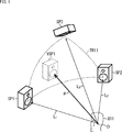
- a listener U11 is in a listening space which is a three-dimensional space, and three speakers SP1 to SP3 are arranged in front of the listener U11.
- the position of the head of the listener U11 is an origin O
- the speakers SP1 to SP3 are located on the surface of a sphere whose center is the origin O.
- gains are distributed to the speakers SP1 to SP3 around the position VSP1.
- the position VSP1 is represented by a three-dimensional vector P having the origin O as a start point and the position VSP1 as an end point.
- the vector L 1 can be represented by a linear sum of the vector L 3.
- equation (1) can be modified to obtain equation (2).
- the coefficients g 1 through coefficient g 3 which was calculated such expressions (2) as the gain, and outputs an audio object signal is a signal of sound of the audio objects to the speaker SP1 to speaker SP3,
- the sound image can be localized at the position VSP1.
- the inverse matrix L 123 -1 can be obtained in advance. Therefore, in VBAP, rendering can be performed with relatively easy calculation, that is, with a small amount of operation.
- the sound image can be properly localized with a small amount of calculation if rendering is performed by panning processing such as VBAP.
- one or more rendering methods are selected from panning processing and rendering processing using a head-related transfer function filter (hereinafter also referred to as head-related transfer function processing) according to the position of the audio object, Made to do the rendering process.
- head-related transfer function processing hereinafter also referred to as head-related transfer function processing
- the rendering method is selected based on the relative positional relationship between the listening position, which is the position of the listener in the listening space, and the position of the audio object.
- panning processing such as VBAP is selected as the rendering method.
- head related transfer function processing is selected as the rendering method.
- FIG. 2 is a diagram illustrating a configuration example of an embodiment of a signal processing device to which the present technology is applied.
- the signal processing device 11 illustrated in FIG. 2 includes a core decoding processing unit 21 and a rendering processing unit 22.
- the core decoding processing unit 21 receives and decodes (decodes) the transmitted input bit stream, and supplies the audio object position information and the audio object signal obtained as a result to the rendering processing unit 22. In other words, the core decoding processing unit 21 acquires audio object position information and an audio object signal.
- the audio object signal is an audio signal for reproducing the sound of the audio object.
- the audio object position information is metadata of an audio object, that is, an audio object signal, which is required for rendering performed in the rendering processing unit 22.
- the audio object position information is information indicating the position in the three-dimensional space of the audio object, that is, in the listening space.
- the rendering processing unit 22 generates an output audio signal based on the audio object position information and the audio object signal supplied from the core decoding processing unit 21 and supplies the output audio signal to a speaker, a recording unit, or the like in the subsequent stage.
- the rendering processing unit 22 selects a rendering method based on the audio object position information, that is, any one of a panning process, a head transfer function process, or a panning process and a head transfer function process as a rendering process. .
- the rendering processing unit 22 performs the selected rendering processing to perform rendering on a playback device such as a speaker or headphone, which is an output destination of the output audio signal, and generates an output audio signal.
- the rendering processing unit 22 may select one or more rendering methods from among three or more different rendering methods including panning processing and head related transfer function processing.
- the rendering processing unit 22 is configured, for example, as shown in FIG.
- the rendering processing unit 22 includes a rendering method selection unit 51, a panning processing unit 52, a head related transfer function processing unit 53, and a mixing processing unit 54.
- the rendering method selection unit 51 is supplied with audio object position information and an audio object signal from the core decoding processing unit 21.
- the rendering method selection unit 51 selects, based on the audio object position information supplied from the core decoding processing unit 21, a method of rendering processing for an audio object, that is, a rendering method, for each audio object.
- the rendering method selection unit 51 is configured to receive at least the panning processing unit 52 and the head related transfer function processing unit 53 of the audio object position information and the audio object signal supplied from the core decoding processing unit 21 according to the selection result of the rendering method. Supply to either one.
- the panning processing unit 52 performs panning processing based on the audio object position information and the audio object signal supplied from the rendering method selecting unit 51, and supplies the panning processing output signal obtained as a result to the mixing processing unit 54.
- the panning processing output signal is an audio signal of each channel for reproducing the sound of the audio object so that the sound image of the sound of the audio object is localized at the position in the listening space indicated by the audio object position information. is there.
- the channel configuration of the output destination of the output audio signal is predetermined, and the audio signal of each channel of that channel configuration is generated as a panning processing output signal.
- the output destination of the output audio signal is the speaker system including the speakers SP1 to SP3 shown in FIG. 1, for example, audio signals of channels corresponding to the speakers SP1 to SP3 are output as panning processing output signals. It is generated.
- an audio signal obtained by multiplying the audio object signal supplied from the rendering method selection unit 51 by the coefficient g 1 which is gain is A panning process output signal of a channel corresponding to the speaker SP1 is used.
- the audio object signal, the audio signal obtained by multiplying each of the coefficients g 2 and the coefficient g 3 is a panning process output signal of the channel corresponding to each of the speakers SP2 and the speaker SP3.
- any processing such as VBAP adopted according to the MPEG-H Part 3: 3D audio standard or a panning method called Speaker-anchored coordinates panner is performed as the panning processing, for example. You may do so.
- VBAP may be selected as the rendering method, or Speaker-anchored coordinates panner may be selected.
- the head related transfer function processing unit 53 performs head related transfer function processing based on the audio object position information and the audio object signal supplied from the rendering method selection unit 51, and the head related transfer function processing output signal obtained as a result is obtained The signal is supplied to the mixing processing unit 54.
- the head related transfer function processing output signal is for each channel for reproducing the sound of the audio object so that the sound image of the sound of the audio object is localized at the position in the listening space indicated by the audio object position information. It is an audio signal.
- the head related transfer function processing output signal corresponds to a panning processing output signal
- the head related transfer function processing output signal and the panning processing output signal are head related transfer function processing when generating an audio signal. Whether it is processing or panning processing is different.
- the above-described panning processing unit 52 and head related transfer function processing unit 53 function as a rendering processing unit that performs rendering processing by the rendering method selected by the rendering method selection unit 51, such as panning processing and head related transfer function processing.
- the mixing processing unit 54 outputs an output audio signal based on at least one of the panning processing output signal supplied from the panning processing unit 52 and the head-related transfer function processing output signal supplied from the head-related transfer function processing unit 53. Generate and output to the latter stage.
- audio object position information of one audio object and an audio object signal are stored in the input bit stream.
- the mixing processing unit 54 performs correction processing to generate an output audio signal.
- the panning processing output signal and the head related transfer function processing output signal are synthesized (blended) for each channel to be an output audio signal.
- the mixing processing unit 54 uses the supplied signal as it is as an output audio signal. .
- audio object position information and audio object signals of a plurality of audio objects are stored in the input bit stream.
- the mixing processing unit 54 performs correction processing as necessary to generate an output audio signal for each audio object.
- the mixing processing unit 54 performs mixing processing of adding (combining) the output audio signal of each audio object obtained as described above for each channel, and the output audio signal of each channel obtained as a result is finally obtained.
- Output audio signal That is, the output audio signals of the same channel obtained for each audio object are added to be the final output audio signal of that channel.
- the mixing processing unit 54 functions as an output audio signal generation unit that generates an output audio signal by performing correction processing or mixing processing that combines the panning processing output signal and the head-related transfer function processing output signal as necessary. Function.
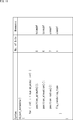
- the audio object position information described above is encoded using, for example, the format shown in FIG. 4 at predetermined time intervals (every predetermined number of frames), and is stored in the input bit stream.
- number_objects indicates the number of audio objects included in the input bit stream.
- tcimsbf is an abbreviation of "Two's complement integer, most significant (sign) bit first", and the sign bit indicates the first two's complement.
- Uimsbf is an abbreviation of "Unsigned integer, most significant bit first”, and the most significant bit indicates a leading unsigned integer.
- position_azimuth [i] As Furthermore, “position_azimuth [i]”, “position_elevation [i]”, and “position_radius [i]” respectively indicate audio object position information of the ith audio object included in the input bit stream.
- position_azimuth [i] indicates the azimuth angle of the position of the audio object in the spherical coordinate system
- position_elevation [i] indicates the elevation angle of the position of the audio object in the spherical coordinate system.
- position_radius [i] indicates the distance to the position of the audio object in the spherical coordinate system, that is, the radius.
- the X axis, the Y axis, and the Z axis which are perpendicular to one another through the origin O are axes of the three-dimensional orthogonal coordinate system.
- the position of the audio object OB11 in the space is X1 which is the X coordinate indicating the position in the X axis direction
- Y1 which is the Y coordinate indicating the position in the Y axis direction
- Z1 which is a Z coordinate indicating X
- the azimuth position_azimuth, elevation angle position_elevation, and radius position_radius are used to represent the position of the audio object OB11 in space.
- a straight line connecting the origin O and the position of the audio object OB11 in the listening space be a straight line r
- a straight line obtained by projecting the straight line r on the XY plane be a straight line L.
- an angle ⁇ formed between the X axis and the straight line L is taken as an azimuth angle position_azimuth indicating the position of the audio object OB11, and this angle ⁇ corresponds to the azimuth angle position_azimuth [i] shown in FIG.
- an angle ⁇ formed between the straight line r and the XY plane is set as an elevation angle position_elevation indicating the position of the audio object OB11, and a length of the straight line r is set as a radius position_radius indicating the position of the audio object OB11.
- the angle ⁇ corresponds to the elevation angle position_elevation [i] shown in FIG. 4, and the length of the straight line r corresponds to the radius position_radius [i] shown in FIG.
- the position of the origin O is the position of a listener (user) who listens to the sound of the content including the sound of the audio object etc.
- the positive direction of the X direction (X axis direction), that is, the near direction in FIG.
- the front direction viewed from the listener is a positive direction in the Y direction (Y axis direction), that is, the right direction in FIG. 5 is the left direction viewed from the listener.
- the position of the audio object is represented by spherical coordinates.
- the position of the audio object in the listening space indicated by such audio object position information is a physical quantity that changes at predetermined time intervals.
- the sound image localization position of the audio object can be moved according to the change of the audio object position information.
- FIG. 6 to FIG. 8 parts corresponding to each other are given the same reference numerals, and the description thereof will be omitted as appropriate. Further, in the present technology, it is assumed that the listening space is a three-dimensional space, but the present technology is also applicable to the case where the listening space is a two-dimensional plane. 6 to 8, in order to simplify the description, it is assumed that the listening space is a two-dimensional plane.
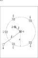
- FIG. 6 there is a listener U21 who is a user who listens to the content sound at the position of the origin O, and used to reproduce the sound of the content on the circumference of a circle of radius R SP centered on the origin O It is assumed that five speakers SP11 to SP15 which are to be connected are disposed. That is, on a horizontal plane including the origin O, the distance from the origin O to each of the speakers SP11 to SP15 is the radius R SP .
- the origin O that is, the distance from the listener U21 to the audio object OBJ1 is R OBJ1
- R OBJ2 the distance from the origin O to the audio object OBJ2 .
- the distance R OBJ1 is a value larger than the radius R SP .
- the distance R OBJ2 is a value smaller than the radius R SP .
- the distance R OBJ1 and the distance R OBJ2 are radius position_radius [i] included in the audio object position information of each of the audio object OBJ1 and the audio object OBJ2.
- the rendering method selection unit 51 selects a rendering method to be performed on the audio object OBJ1 and the audio object OBJ2 by comparing the predetermined radius R SP with the distance R OBJ1 and the distance R OBJ2 .
- panning processing is selected as the rendering method.
- head related transfer function processing is selected as the rendering method.
- the panning process is selected for the audio object OBJ1 of which the distance R OBJ1 is equal to or greater than the radius R SP in this example, and the audio object position information of the audio object OBJ1 and the audio object signal are supplied to the panning process unit 52. Then, in the panning processing unit 52, processing such as VBAP described with reference to FIG. 1 is performed on the audio object OBJ1 as panning processing.
- the head related transfer function processing is selected, and the audio object position information of the audio object OBJ2 and the audio object signal are supplied to the head related transfer function processing unit 53. Be done.
- head related transfer function processing unit 53 head related transfer function processing using the head related transfer function is performed on the audio object OBJ2 as shown in FIG. 7, for example, and the head related transfer function for the audio object OBJ2 is A processing output signal is generated.
- the head related transfer function processing unit 53 prepares each of the left and right ears prepared in advance with respect to the position in the listening space of the audio object OBJ2 based on the audio object position information of the audio object OBJ2. Read out the head related transfer function, more specifically the head related transfer function filter.
- sampling points For example, several points in the area inside the circle (on the side of the origin O) in which the speakers SP11 to SP15 are arranged are used as sampling points. Then, for each of the sampling points, a head-related transfer function indicating the transfer characteristic of sound from the sampling point to the ear of the listener U21 at the origin O is prepared in advance for each of the left and right ears. Shall be held by
- the head related transfer function processing unit 53 reads the head related transfer function of the sampling point closest to the position of the audio object OBJ2 as the head related transfer function of the position of the audio object OBJ2.
- a head-related transfer function at the position of the audio object OBJ2 may be generated by interpolation processing such as linear interpolation from head-related transfer functions of several sampling points in the vicinity of the position of the audio object OBJ2.
- a head-related transfer function on the position of the audio object OBJ2 may be stored in the metadata of the input bit stream.
- the rendering method selection unit 51 supplies the audio object position information and the head-related transfer function supplied from the core decoding processing unit 21 to the head-related transfer function processing unit 53 as metadata.
- the head-related transfer function with respect to the position of the audio object will in particular also be referred to as the object position head-related transfer function.
- the head related transfer function processing unit 53 outputs an audio signal (a signal of sound presented to the ears of the left and right ears of the listener U21)
- a speaker (channel) supplied as a head-related transfer function processing output signal) is selected.
- the speaker to which the output audio signal of the sound to be presented to the left or right ear of the listener U21 is to be output is also referred to as a selection speaker in particular.
- the head related transfer function processing unit 53 selects the speaker SP11 disposed at the position closest to the audio object OBJ2 on the left side of the audio object OBJ2 as viewed from the listener U21 as a selected speaker for the left ear Do. Similarly, the head related transfer function processing unit 53 selects the speaker SP13 disposed at the position closest to the audio object OBJ2 on the right side of the audio object OBJ2 as viewed from the listener U21 as a selection speaker for the right ear .
- the head related transfer function processing unit 53 obtains a head related transfer function, more specifically, a filter for the head related transfer function with respect to the arrangement positions of those selected speakers.
- the head related transfer function processing unit 53 appropriately performs interpolation processing based on the head related transfer function of each sampling point held in advance, and the head at each position of the speaker SP11 and the speaker SP13 Generate a transfer function.
- the head related transfer function about the arrangement position of each speaker may be previously held in the head related transfer function processing unit 53, or the head related transfer function of the arrangement position of the selected speaker is metadata as metadata. It may be stored in the input bit stream.
- the head-related transfer function of the arrangement position of the selected speaker will be particularly referred to as a speaker position head-related transfer function.
- the head related transfer function processing unit 53 convolutes the audio object signal of the audio object OBJ2 with the object position head related transfer function of the left ear, and the signal obtained as a result, the speaker position head related transmission of the left ear The function is convoluted to generate an audio signal for the left ear.
- the head related transfer function processing unit 53 convolutes the audio object signal of the audio object OBJ2 with the object position head related transfer function of the right ear, and the resulting signal, and the speaker position head of the right ear A partial transfer function is convoluted to generate an audio signal for the right ear.
- the audio signal for the left ear and the audio signal for the right ear present the sound of the audio object OBJ2 so that the listener U21 can perceive it as if the sound could be heard from the position of the audio object OBJ2. It is a signal to do. That is, it is an audio signal that realizes sound image localization to the position of the audio object OBJ2.
- the reproduced sound O2 SP11 is presented to the left ear of the listener U21, and at the same time the sound is transmitted by the speaker SP13 based on the audio signal for the right ear
- the reproduced sound O2 SP13 is presented to the right ear of the listener U21.
- the listener U21 is perceived as if the sound of the audio object OBJ2 is heard from the position of the audio object OBJ2.
- the reproduction sound O2 SP11 is represented by an arrow connecting the speaker SP11 and the left ear of the listener U21
- the reproduction sound O2 SP13 is represented by an arrow connecting the speaker SP13 and the right ear of the listener U21.
- the reproduced sound O2 SP11-CT is a crosstalk component of the reproduced sound O2 SP11 that leaks to the right ear of the listener U21. That is, the reproduced sound O2 SP11-CT is a crosstalk component of the reproduced sound O2 SP11 that reaches the ear (here, the right ear) different from the purpose of the listener U21.
- the reproduced sound O2 SP13-CT propagating from the speaker SP13 to the left ear of the listener U21 is the speaker SP13 and the listener U21. It is represented by an arrow connecting the left ear.
- the reproduced sound O2 SP13-CT is a crosstalk component of the reproduced sound O2 SP13 .
- the head related transfer function processing unit 53 Based on the audio signal for the left ear, the head related transfer function processing unit 53 generates a cancel signal for canceling the reproduced sound O2 SP11-CT which is a crosstalk component, and the audio signal for the left ear and the cancel signal And generate a final left-ear audio signal. Then, the final left-ear audio signal including the crosstalk cancellation component and the space transfer function correction component obtained in this manner is taken as the head-related transfer function processed output signal of the channel corresponding to the speaker SP11. Ru.
- the head related transfer function processing unit 53 based on the audio signal for the right ear, the head related transfer function processing unit 53 generates a cancellation signal for canceling the reproduced sound O2 SP13-CT , which is a crosstalk component, and generates an audio signal for the right ear.
- a final right ear audio signal is generated based on the cancellation signal. Then, the final right-ear audio signal including the crosstalk cancellation component and the space transfer function correction component obtained in this manner is used as a head transfer function processing output signal of the channel corresponding to the speaker SP13.
- transaural process The process of rendering on the speaker including the crosstalk correction process of generating the audio signal for the left ear and the audio signal for the right ear as described above is called transaural process.
- transaural processing is described in detail, for example, in JP-A-2016-140039.
- an example in which one speaker is selected for each of the left and right ears as the selected speaker has been described, but two or more speakers are selected for each of the left and right ears as the selected speakers.
- An audio signal for the left ear or an audio signal for the right ear may be generated.
- all the speakers constituting the speaker system such as the speakers SP11 to SP15, may be selected as the selection speakers.
- binaural processing may be performed as head related transfer function processing.
- Binaural processing is rendering processing for rendering an audio object (audio object signal) on an output unit such as headphones worn on the left and right ears using a head-related transfer function.
- panning processing for distributing gains to the left and right channels is selected as a rendering method.
- binaural processing is selected as the rendering method.
- the audio object may gradually approach the listener U21 with time from a position at a distance greater than or equal to the radius R SP .
- the audio object OBJ2 that is at a position longer than the radius R SP as viewed from the listener U21 at a predetermined time is depicted as approaching the listener U21 with time.
- an area inside a circle of radius R SP centered at the origin O is a speaker radius area RG11
- an area inside a circle of radius R HRTF centered at the origin O is a HRTF area RG12
- a speaker radius area RG11 the region is not a HRTF region RG12 of the transition region R TS.
- the transition area R TS is an area where the distance from the origin O (the listener U 21) is a distance between the radius R HRTF and the radius R SP .
- the rendering method switches suddenly when the audio object OBJ 2 reaches the inside of the transition area R TS. It will be. Then, a discontinuous point occurs in the sound of the audio object OBJ2, which may cause a sense of discomfort.
- panning processing is selected as the rendering method.
- HRTF processing is selected as the rendering method.
- the correction process is performed so as closer to the panning process output signal.
- the panning processing output signal of the channel corresponding to the speaker SP11 generated by the panning processing is O2 PAN11 (R 0 )
- the panning processing output signal of the channel corresponding to the speaker SP13 is O2 PAN13 (R 0 ).
- the head related transfer function processed output signal of the channel corresponding to the speaker SP11 generated by the head related transfer function processing is O2 HRTF11 (R 0 ), and the head related transfer function processed output signal of the channel corresponding to the speaker SP13 It is set as O2 HRTF13 (R 0 ).
- the output audio signal O2 SP11 (R 0 ) of the channel corresponding to the speaker SP11 and the output audio signal O2 SP13 (R 0 ) of the channel corresponding to the speaker SP13 are calculated by calculating the following equation (3) You can get it. That is, in the mixing processing unit 54, the calculation of the following Expression (3) is performed as the correction processing.
- the panning process output signal and the head transmitted proration ratio according to the distance R 0 to the audio object function processing adds the output signal (synthesis) to A correction process is performed to obtain an output audio signal.
- the output of the panning process and the output of the head related transfer function process are proportionally divided according to the distance R 0 .
- the listening position where the listener is present is the origin O
- the case where the listening position is always the same position is described as an example, but the listener may move with time.
- the position of the listener at each time may be set as the origin O, and the relative position of the audio object or the speaker viewed from the origin O may be recalculated.
- step S11 the core decoding processing unit 21 decodes (decodes) the received input bit stream, and supplies the audio object position information and the audio object signal obtained as a result to the rendering method selecting unit 51.
- step S12 the rendering method selection unit 51 determines, based on the audio object position information supplied from the core decode processing unit 21, whether to perform panning processing as rendering of the audio object.
- step S12 when the distance from the listener indicated by the audio object position information to the audio object is equal to or larger than the radius R HRTF described with reference to FIG. That is, at least panning is selected as the rendering method.
- step S12 when there is an instruction input instructing whether or not to perform the panning process by a user who operates the signal processing apparatus 11 or the like, and the execution of the panning process is designated (instruction) by the instruction input, step S12. It may be determined that the panning process is to be performed. In this case, the rendering method to be executed is selected by the instruction input by the user or the like.
- step S12 If it is determined in step S12 that the panning process is not to be performed, the process of step S13 is not performed, and then the process proceeds to step S14.
- step S12 when it is determined in step S12 that the panning process is to be performed, the rendering method selecting unit 51 supplies the audio object position information and the audio object signal supplied from the core decoding processing unit 21 to the panning processing unit 52. After that, the process proceeds to step S13.
- step S13 the panning processing unit 52 performs panning processing based on the audio object position information and the audio object signal supplied from the rendering method selecting unit 51, and generates a panning processing output signal.
- step S13 the above-described VBAP or the like is performed as the panning process.
- the panning processing unit 52 supplies the panning processing output signal obtained by the panning processing to the mixing processing unit 54.
- step S14 If it is determined that the process of step S13 is performed or if the panning process is not performed in step S12, the process of step S14 is performed.
- step S14 the rendering method selection unit 51 determines, based on the audio object position information supplied from the core decode processing unit 21, whether or not head-related transfer function processing is to be performed as rendering of the audio object.
- step S14 when the distance from the listener indicated by the audio object position information to the audio object is less than the radius R SP described with reference to FIG. That is, at least head-related transfer function processing is selected as the rendering method.
- step S14 there is an instruction input for instructing whether or not to perform head-related transfer function processing by a user who operates the signal processing apparatus 11 or the like, and execution of the head-related transfer function processing is designated (instruction) by the instruction input. In this case, it may be determined in step S14 that head related transfer function processing is to be performed.
- step S14 If it is determined in step S14 that head-related transfer function processing is not to be performed, the processing in steps S15 to S19 is not performed, and then the processing proceeds to step S20.
- step S14 when it is determined in step S14 that the head-related transfer function processing is to be performed, the rendering method selection unit 51 performs head-related transfer function on the audio object position information and the audio object signal supplied from the core decoding processing unit 21. After supplying the processing unit 53, the process proceeds to step S15.
- step S ⁇ b> 15 the head related transfer function processing unit 53 acquires an object position head related transfer function of the position of the audio object based on the audio object position information supplied from the rendering method selection unit 51.
- the object position head-related transfer function may be read out in advance, or may be obtained by interpolation processing from a plurality of head-related transfer functions held in advance, or from the input bit stream It may be read out.
- step S16 the head related transfer function processing unit 53 selects a selected speaker based on the audio object position information supplied from the rendering method selection unit 51, and acquires a speaker position head related transfer function of the selected speaker position. .
- the speaker position head transfer function may be read out in advance, or may be obtained by interpolation processing from a plurality of head transfer functions held in advance, or from the input bit stream It may be read out.
- step S17 the head related transfer function processing unit 53 convolutes the audio object signal supplied from the rendering method selection unit 51 with the object position head related transfer function obtained in step S15 for each of the left and right ears.
- step S18 the head related transfer function processing unit 53 convolutes the audio signal obtained in step S17 and the speaker position head related transfer function for each of the left and right ears. Thereby, an audio signal for the left ear and an audio signal for the right ear can be obtained.
- step S19 the head related transfer function processing unit 53 generates a head related transfer function processing output signal based on the audio signal for the left ear and the audio signal for the right ear, and supplies the generated signal to the mixing processing unit 54.
- the cancel signal is appropriately generated to generate the final head related transfer function processing output signal.
- the transaural process described with reference to FIG. 8 as head-related transfer function processing is performed, and a head-related transfer function processed output signal is generated.
- a head-related transfer function processed output signal is generated.
- the output destination of the output audio signal is not a speaker but a playback device such as headphones, binaural processing or the like is performed as head-related transfer function processing, and a head-related transfer function processing output signal is generated.
- step S19 If the process of step S19 is performed or it is determined in step S14 that the head related transfer function process is not performed, the process of step S20 is performed thereafter.
- step S20 the mixing processing unit 54 combines the panning processing output signal supplied from the panning processing unit 52 and the head-related transfer function processing output signal supplied from the head-related transfer function processing unit 53, and outputs an output audio signal.
- step S20 the calculation of the equation (3) described above is performed as a correction process to generate an output audio signal.
- step S13 the process of step S13 is performed, and the process of step S15 to step S19 is not performed, or the process of step S15 to step S19 is performed and the process of step S13 is not performed. There is no processing.
- the panning process output signal obtained as a result is used as the output audio signal as it is.
- the head-related transfer function processed output signal obtained as a result is used as an output audio signal as it is.
- the mixing processing unit 54 performs the mixing process It will be. That is, the output audio signals obtained for each audio object are added (combined) for each channel to be one final output audio signal.
- the mixing processing unit 54 outputs the obtained output audio signal to the subsequent stage, and the audio output processing ends.
- the signal processing apparatus 11 selects one or more rendering methods from the plurality of rendering methods based on the audio object position information, that is, based on the distance from the listening position to the audio object. Then, the signal processing device 11 performs rendering according to the selected rendering method to generate an output audio signal.
- panning processing is selected as the rendering method.
- the audio object is sufficiently far from the listening position, it is not necessary to consider the difference in the arrival time of the sound to the listener's left and right ears, and the sound image is localized with sufficient reproducibility even with a small amount of computation. be able to.
- the audio object is at a position close to the listening position, for example, HRTF processing is selected as the rendering method.
- HRTF processing is selected as the rendering method.
- the sound image can be localized with sufficient reproducibility, although the amount of calculation increases somewhat.
- the head-related transfer function processing is selected as the rendering method. It may be selected.
- head-related transfer function processing is selected as a rendering method
- head-related transfer functions are performed using head-related transfer functions according to the distance from the listening position to the audio object, It is possible to prevent the occurrence of discontinuous points.
- the head related transfer function processing unit 53 As the distance to the audio object is longer, that is, as the position of the audio object is closer to the boundary position of the speaker radius area RG11, the head related transfer functions of the left and right ears are substantially It should be made to become the same thing.
- the increase in the degree of similarity of the head transfer functions can mean that the difference between the head transfer functions for the left ear and the head transfer functions for the right ear is reduced.
- a common head related transfer function is used for the left and right ears.
- the head related transfer function processing unit 53 determines the actual position of the audio object. The one close to the head related transfer function obtained by the measurement is used.
- the head transfer function processing output signal becomes the same as the panning processing output signal. It is.
- the resource availability of the signal processing device 11, the importance of the audio object, etc. may be taken into consideration.
- the rendering method selection unit 51 selects head-related transfer function processing as the rendering method. Conversely, the rendering method selection unit 51 selects panning processing as the rendering method when the resource availability of the signal processing device 11 is small.
- the rendering method selection unit 51 selects head-related transfer function processing as the rendering method.
- the rendering method selection unit 51 selects panning as the rendering method.
- the importance of each audio object may be included in the input bitstream as metadata of the audio objects. Also, the importance of the audio object may be designated by an external operation input or the like.
- rendering for headphone reproduction may be performed using the concept of a virtual speaker.
- the computational cost for performing head-related transfer function processing becomes large, as in the case of rendering on a speaker.
- the output destination of the output audio signal is a playback device such as headphones that performs playback on the left and right two channels, and once rendering to a virtual speaker, the playback device further uses a head related transfer function.
- the present technology is also applicable when rendering is performed.
- the rendering method selection unit 51 may select one or more rendering methods at the time of rendering from among a plurality of rendering methods, for example, regarding the speakers SP11 to SP15 illustrated in FIG. 8 as virtual speakers. .
- the panning method is selected as the rendering method It should be done.
- rendering to a virtual speaker is performed by panning processing. Then, based on the audio signal obtained by the panning process and the head transfer function for each of the left and right ears from the virtual speaker to the listening position, the head transfer function processing further renders the headphone or the like to a reproduction device Is performed to generate an output audio signal.
- head related transfer function processing may be selected as the rendering method.
- binaural processing as head-related transfer function processing directly performs rendering on a reproduction device such as headphones to generate an output audio signal.
- the encoding format based on the present technology that is, the metadata of the audio object is as shown in FIG. 10, for example.
- radius_hrtf is information (parameter) indicating the distance from the listening position (origin O), which is used to determine whether or not head-related transfer function processing is selected as the rendering method.
- radius_panning is information (parameter) indicating the distance from the listening position (origin O), which is used to determine whether or not panning is selected as the rendering method.
- the metadata stores the audio object position information of each audio object, the distance radius_hrtf, and the distance radius_panning. These pieces of information are read by the core decoding processing unit 21 as metadata. It is output to the rendering method selection unit 51.
- the rendering method selection unit 51 selects head related transfer function processing as the rendering method if the distance from the listener to the audio object is equal to or less than the distance radius_hrtf regardless of the radius R SP indicating the distance to each speaker Do. In addition, the rendering method selection unit 51 does not select head-related transfer function processing as the rendering method if the distance from the listener to the audio object is longer than the distance radius_hrtf.
- the rendering method selection unit 51 selects panning processing as the rendering method if the distance from the listener to the audio object is equal to or more than the distance radius_panning. In addition, the rendering method selection unit 51 does not select the panning process as the rendering method if the distance from the listener to the audio object is shorter than the distance radius_panning.
- the distance radius_hrtf and the distance radius_panning may be the same distance or different distances from each other.
- both the panning process and the head-related transfer function process are selected as the rendering method when the distance from the listener to the audio object is greater than or equal to the distance radius_panning and less than or equal to the distance radius_hrtf.
- the mixing processing unit 54 performs the calculation of the equation (3) described above based on the panning process output signal and the head-related transfer function process output signal to generate an output audio signal. That is, according to the distance from the listener to the audio object, the correction processing divides the panning processing output signal and the head related transfer function processing output signal to generate an output audio signal.
- ⁇ Modified Example 1 of Third Embodiment> On selection of rendering method> Furthermore, on the output side of the input bit stream, that is, the creator side of the content, a rendering method at each time such as a frame is selected for each audio object, and selection instruction information indicating the selection result is input as metadata. It may be stored in a stream.
- the selection instruction information is information indicating an instruction for selecting a rendering method for the audio object
- the rendering method selection unit 51 performs rendering based on the selection instruction information supplied from the core decoding processing unit 21. Choose a method. In other words, the rendering method selection unit 51 selects the rendering method designated by the selection instruction information for the audio object signal.
- the encoding format based on the present technology that is, the metadata of the audio object is as shown in FIG. 11, for example.
- Flg_rendering_type is selection instruction information indicating which rendering method to use.
- the selection instruction information flg_rendering_type is flag information (parameter) indicating whether to select panning processing or head-related transfer function processing as the rendering method.
- the value “0” of the selection instruction information flg_rendering_type indicates that the panning process is selected as the rendering method.
- the value “1” of the selection indication information flg_rendering_type indicates that the head-related transfer function processing is selected as the rendering method.
- selection designation information flg_rendering_type is stored in the metadata for each audio object for each frame (each time).
- audio object position information and selection instruction information flg_rendering_type are stored in the metadata for each audio object, and these pieces of information are read out by the core decoding processing unit 21 as metadata. , And supplied to the rendering method selection unit 51.
- the rendering method selection unit 51 selects the rendering method according to the value of the selection instruction information flg_rendering_type regardless of the distance from the listener to the audio object. That is, the rendering method selection unit 51 selects panning as the rendering method if the value of the selection instruction information flg_rendering_type is “0”, and transmits the head transmission as the rendering method if the value of the selection instruction information flg_rendering_type is “1”. Select function processing.
- the selection instruction information flg_rendering_type may be any of a plurality of three or more types of values. Good. For example, when the value of the selection instruction information flg_rendering_type is “2”, panning processing and head-related transfer function processing may be selected as the rendering method.
- the present technology as described in, for example, the first to third modifications of the first embodiment, even when there are a large number of audio objects, the amount of computation is reduced while the amount of computation is high. Sound image expression with reproducibility can be realized.
- the present technology is applicable not only to speaker reproduction using an actual speaker, but also to headphone reproduction by rendering using a virtual speaker.
- the series of processes described above can be executed by hardware or software.
- a program that configures the software is installed on a computer.
- the computer includes, for example, a general-purpose personal computer that can execute various functions by installing a computer incorporated in dedicated hardware and various programs.
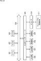
- FIG. 12 is a block diagram showing an example of a hardware configuration of a computer that executes the series of processes described above according to a program.
- a central processing unit (CPU) 501 a read only memory (ROM) 502, and a random access memory (RAM) 503 are mutually connected by a bus 504.
- CPU central processing unit
- ROM read only memory
- RAM random access memory
- an input / output interface 505 is connected to the bus 504.
- An input unit 506, an output unit 507, a recording unit 508, a communication unit 509, and a drive 510 are connected to the input / output interface 505.
- the input unit 506 includes a keyboard, a mouse, a microphone, an imaging device, and the like.
- the output unit 507 includes a display, a speaker, and the like.
- the recording unit 508 includes a hard disk, a non-volatile memory, and the like.
- the communication unit 509 is formed of a network interface or the like.
- the drive 510 drives a removable recording medium 511 such as a magnetic disk, an optical disk, a magneto-optical disk, or a semiconductor memory.
- the CPU 501 loads, for example, the program recorded in the recording unit 508 into the RAM 503 via the input / output interface 505 and the bus 504, and executes the above-described series. Processing is performed.
- the program executed by the computer (CPU 501) can be provided by being recorded on, for example, a removable recording medium 511 as a package medium or the like. Also, the program can be provided via a wired or wireless transmission medium such as a local area network, the Internet, or digital satellite broadcasting.
- the program can be installed in the recording unit 508 via the input / output interface 505 by attaching the removable recording medium 511 to the drive 510. Also, the program can be received by the communication unit 509 via a wired or wireless transmission medium and installed in the recording unit 508. In addition, the program can be installed in advance in the ROM 502 or the recording unit 508.
- the program executed by the computer may be a program that performs processing in chronological order according to the order described in this specification, in parallel, or when necessary, such as when a call is made. It may be a program to be processed.
- the present technology can have a cloud computing configuration in which one function is shared and processed by a plurality of devices via a network.
- each step described in the above-described flowchart can be executed by one device or in a shared manner by a plurality of devices.
- the plurality of processes included in one step can be executed by being shared by a plurality of devices in addition to being executed by one device.
- present technology can also be configured as follows.
- a rendering method selection unit that selects one or more of a plurality of different rendering methods for rendering a sound image of an audio signal in the listening space; A rendering processing unit that performs the rendering process of the audio signal according to the method selected by the rendering method selection unit.
- the plurality of techniques include panning processing.
- the signal processing apparatus according to any one of (1) to (3), wherein the plurality of techniques include the rendering process using a head related transfer function.
- the signal processing device according to (4), wherein the rendering process using the head related transfer function is a transaural process or a binaural process.
- the rendering processing unit performs the rendering process so that the difference between the head related transfer function for the left ear and the head related transfer function for the right ear decreases as the distance approaches the first distance.
- the signal processing apparatus according to (9), wherein the head related transfer function to be used is selected.
- the rendering method selection unit selects the rendering process using a head related transfer function as a method of the rendering process (7).
- the signal processing device as described.
- the rendering method selection unit performs the rendering process using the panning process and the head related transfer function as a method of the rendering process.
- the signal processing device according to (11).
- An output audio signal generation unit that combines an signal obtained by the panning process and a signal obtained by the rendering process using the head related transfer function to generate an output audio signal Signal processing equipment.
- the signal processing apparatus according to any one of (1) to (5), wherein the rendering method selection unit selects a method specified for the audio signal as a method of the rendering process.
- the signal processor Select one or more rendering methods for localization of the sound image of the audio signal in the listening space from among different methods, A signal processing method for performing the rendering process of the audio signal according to a selected method.
- Reference Signs List 11 signal processing device 21 core decoding processing unit, 22 rendering processing unit, 51 rendering method selecting unit, 52 panning processing unit, 53 head transfer function processing unit, 54 mixing processing unit
Landscapes
- Engineering & Computer Science (AREA)
- Physics & Mathematics (AREA)
- Acoustics & Sound (AREA)
- Signal Processing (AREA)
- Multimedia (AREA)
- Mathematical Physics (AREA)
- Computational Linguistics (AREA)
- Health & Medical Sciences (AREA)
- Audiology, Speech & Language Pathology (AREA)
- Human Computer Interaction (AREA)
- Stereophonic System (AREA)
- Circuit For Audible Band Transducer (AREA)
Abstract
Description
〈本技術について〉
本技術は、オーディオオブジェクトのレンダリングを行う場合に、オーディオオブジェクトごとに、そのオーディオオブジェクトの聴取空間内の位置に応じて、互いに異なる複数のレンダリング手法のなかから1以上の手法を選択することで、少ない演算量でも音像の再現性を向上させることができるようにするものである。すなわち、本技術は、少ない演算量でも本来意図した位置に音像があるかのように知覚させる音像定位を実現することができるようにするものである。
それでは、以下、本技術についてより詳細に説明する。
次に、図2に示した信号処理装置11のレンダリング処理部22のより詳細な構成例について説明する。
ところで、上述したオーディオオブジェクト位置情報は、例えば所定の時間間隔ごと(所定フレーム数ごと)に図4に示すフォーマットが用いられて符号化され、入力ビットストリームに格納される。
次に、レンダリング手法選択部51によるレンダリング手法の選択の具体的な例について、図6乃至図8を参照して説明する。

次に、信号処理装置11の具体的な動作について説明する。すなわち、以下、図9のフローチャートを参照して、信号処理装置11によるオーディオ出力処理について説明する。なお、ここでは説明を簡単にするため、入力ビットストリームには1つ分のオーディオオブジェクトのデータのみが格納されているものとして説明を行う。
〈頭部伝達関数処理について〉
また、以上においては、頭部伝達関数処理としてトランスオーラル処理が行われる例について説明した。つまり頭部伝達関数処理ではスピーカへのレンダリングが行われる例について説明した。
〈レンダリング手法の選択について〉
また、レンダリング手法を選択するにあたり、すなわちレンダリング手法を切り替えるにあたり、フレーム等の各時刻においてレンダリング手法を選択するのに必要となるパラメータの一部または全部が入力ビットストリームに格納されて伝送されてもよい。
〈レンダリング手法の選択について〉
さらに、入力ビットストリームの出力側、つまりコンテンツの制作者側において、オーディオオブジェクトごとにフレーム等の各時刻でのレンダリング手法を選択しておき、その選択結果を示す選択指示情報をメタデータとして入力ビットストリームに格納するようにしてもよい。
ところで、上述した一連の処理は、ハードウェアにより実行することもできるし、ソフトウェアにより実行することもできる。一連の処理をソフトウェアにより実行する場合には、そのソフトウェアを構成するプログラムが、コンピュータにインストールされる。ここで、コンピュータには、専用のハードウェアに組み込まれているコンピュータや、各種のプログラムをインストールすることで、各種の機能を実行することが可能な、例えば汎用のパーソナルコンピュータなどが含まれる。
オーディオ信号の音像を聴取空間内に定位させるレンダリング処理の手法を、互いに異なる複数の手法のなかから1以上選択するレンダリング手法選択部と、
前記レンダリング手法選択部によって選択された手法により前記オーディオ信号の前記レンダリング処理を行うレンダリング処理部と
を備える信号処理装置。
(2)
前記オーディオ信号は、オーディオオブジェクトのオーディオ信号である
(1)に記載の信号処理装置。
(3)
前記複数の手法には、パニング処理が含まれている
(1)または(2)に記載の信号処理装置。
(4)
前記複数の手法には、頭部伝達関数を用いた前記レンダリング処理が含まれている
(1)乃至(3)の何れか一項に記載の信号処理装置。
(5)
前記頭部伝達関数を用いた前記レンダリング処理は、トランスオーラル処理またはバイノーラル処理である
(4)に記載の信号処理装置。
(6)
前記レンダリング手法選択部は、前記聴取空間内における前記オーディオオブジェクトの位置に基づいて前記レンダリング処理の手法を選択する
(2)に記載の信号処理装置。
(7)
前記レンダリング手法選択部は、聴取位置から前記オーディオオブジェクトまでの距離が所定の第1の距離以上である場合、前記レンダリング処理の手法としてパニング処理を選択する
(6)に記載の信号処理装置。
(8)
前記レンダリング手法選択部は、前記距離が前記第1の距離未満である場合、前記レンダリング処理の手法として頭部伝達関数を用いた前記レンダリング処理を選択する
(7)に記載の信号処理装置。
(9)
前記レンダリング処理部は、前記距離が前記第1の距離未満である場合、前記聴取位置から前記オーディオオブジェクトまでの前記距離に応じた前記頭部伝達関数を用いて前記レンダリング処理を行う
(8)に記載の信号処理装置。
(10)
前記レンダリング処理部は、前記距離が前記第1の距離に近くなるほど、左耳用の前記頭部伝達関数と右耳用の前記頭部伝達関数との差が小さくなるように、前記レンダリング処理に用いる前記頭部伝達関数を選択する
(9)に記載の信号処理装置。
(11)
前記レンダリング手法選択部は、前記距離が前記第1の距離とは異なる第2の距離未満である場合、前記レンダリング処理の手法として頭部伝達関数を用いた前記レンダリング処理を選択する
(7)に記載の信号処理装置。
(12)
前記レンダリング手法選択部は、前記距離が前記第1の距離以上かつ前記第2の距離未満である場合、前記レンダリング処理の手法として、前記パニング処理および前記頭部伝達関数を用いた前記レンダリング処理を選択する
(11)に記載の信号処理装置。
(13)
前記パニング処理により得られた信号と、前記頭部伝達関数を用いた前記レンダリング処理により得られた信号とを合成して出力オーディオ信号を生成する出力オーディオ信号生成部をさらに備える
(12)に記載の信号処理装置。
(14)
前記レンダリング手法選択部は、前記レンダリング処理の手法として、前記オーディオ信号に対して指定された手法を選択する
(1)乃至(5)の何れか一項に記載の信号処理装置。
(15)
信号処理装置が、
オーディオ信号の音像を聴取空間内に定位させるレンダリング処理の手法を、互いに異なる複数の手法のなかから1以上選択し、
選択された手法により前記オーディオ信号の前記レンダリング処理を行う
信号処理方法。
(16)
オーディオ信号の音像を聴取空間内に定位させるレンダリング処理の手法を、互いに異なる複数の手法のなかから1以上選択し、
選択された手法により前記オーディオ信号の前記レンダリング処理を行う
ステップを含む処理をコンピュータに実行させるプログラム。
Claims (16)
- オーディオ信号の音像を聴取空間内に定位させるレンダリング処理の手法を、互いに異なる複数の手法のなかから1以上選択するレンダリング手法選択部と、
前記レンダリング手法選択部によって選択された手法により前記オーディオ信号の前記レンダリング処理を行うレンダリング処理部と
を備える信号処理装置。 - 前記オーディオ信号は、オーディオオブジェクトのオーディオ信号である
請求項1に記載の信号処理装置。 - 前記複数の手法には、パニング処理が含まれている
請求項1に記載の信号処理装置。 - 前記複数の手法には、頭部伝達関数を用いた前記レンダリング処理が含まれている
請求項1に記載の信号処理装置。 - 前記頭部伝達関数を用いた前記レンダリング処理は、トランスオーラル処理またはバイノーラル処理である
請求項4に記載の信号処理装置。 - 前記レンダリング手法選択部は、前記聴取空間内における前記オーディオオブジェクトの位置に基づいて前記レンダリング処理の手法を選択する
請求項2に記載の信号処理装置。 - 前記レンダリング手法選択部は、聴取位置から前記オーディオオブジェクトまでの距離が所定の第1の距離以上である場合、前記レンダリング処理の手法としてパニング処理を選択する
請求項6に記載の信号処理装置。 - 前記レンダリング手法選択部は、前記距離が前記第1の距離未満である場合、前記レンダリング処理の手法として頭部伝達関数を用いた前記レンダリング処理を選択する
請求項7に記載の信号処理装置。 - 前記レンダリング処理部は、前記距離が前記第1の距離未満である場合、前記聴取位置から前記オーディオオブジェクトまでの前記距離に応じた前記頭部伝達関数を用いて前記レンダリング処理を行う
請求項8に記載の信号処理装置。 - 前記レンダリング処理部は、前記距離が前記第1の距離に近くなるほど、左耳用の前記頭部伝達関数と右耳用の前記頭部伝達関数との差が小さくなるように、前記レンダリング処理に用いる前記頭部伝達関数を選択する
請求項9に記載の信号処理装置。 - 前記レンダリング手法選択部は、前記距離が前記第1の距離とは異なる第2の距離未満である場合、前記レンダリング処理の手法として頭部伝達関数を用いた前記レンダリング処理を選択する
請求項7に記載の信号処理装置。 - 前記レンダリング手法選択部は、前記距離が前記第1の距離以上かつ前記第2の距離未満である場合、前記レンダリング処理の手法として、前記パニング処理および前記頭部伝達関数を用いた前記レンダリング処理を選択する
請求項11に記載の信号処理装置。 - 前記パニング処理により得られた信号と、前記頭部伝達関数を用いた前記レンダリング処理により得られた信号とを合成して出力オーディオ信号を生成する出力オーディオ信号生成部をさらに備える
請求項12に記載の信号処理装置。 - 前記レンダリング手法選択部は、前記レンダリング処理の手法として、前記オーディオ信号に対して指定された手法を選択する
請求項1に記載の信号処理装置。 - 信号処理装置が、
オーディオ信号の音像を聴取空間内に定位させるレンダリング処理の手法を、互いに異なる複数の手法のなかから1以上選択し、
選択された手法により前記オーディオ信号の前記レンダリング処理を行う
信号処理方法。 - オーディオ信号の音像を聴取空間内に定位させるレンダリング処理の手法を、互いに異なる複数の手法のなかから1以上選択し、
選択された手法により前記オーディオ信号の前記レンダリング処理を行う
ステップを含む処理をコンピュータに実行させるプログラム。
Priority Applications (8)
| Application Number | Priority Date | Filing Date | Title |
|---|---|---|---|
| JP2019559531A JP7283392B2 (ja) | 2017-12-12 | 2018-11-28 | 信号処理装置および方法、並びにプログラム |
| US16/770,565 US11310619B2 (en) | 2017-12-12 | 2018-11-28 | Signal processing device and method, and program |
| RU2020116581A RU2020116581A (ru) | 2017-12-12 | 2018-11-28 | Программа, способ и устройство для обработки сигнала |
| EP18887300.4A EP3726859A4 (en) | 2017-12-12 | 2018-11-28 | SIGNAL PROCESSING DEVICE AND METHOD AND PROGRAM |
| CN201880077702.6A CN111434126B (zh) | 2017-12-12 | 2018-11-28 | 信号处理装置和方法以及程序 |
| CN202210366454.5A CN114710740A (zh) | 2017-12-12 | 2018-11-28 | 信号处理装置和方法以及计算机可读存储介质 |
| KR1020207014699A KR102561608B1 (ko) | 2017-12-12 | 2018-11-28 | 신호 처리 장치 및 방법, 그리고 프로그램 |
| US17/709,550 US11838742B2 (en) | 2017-12-12 | 2022-03-31 | Signal processing device and method, and program |
Applications Claiming Priority (2)
| Application Number | Priority Date | Filing Date | Title |
|---|---|---|---|
| JP2017237402 | 2017-12-12 | ||
| JP2017-237402 | 2017-12-12 |
Related Child Applications (2)
| Application Number | Title | Priority Date | Filing Date |
|---|---|---|---|
| US16/770,565 A-371-Of-International US11310619B2 (en) | 2017-12-12 | 2018-11-28 | Signal processing device and method, and program |
| US17/709,550 Continuation US11838742B2 (en) | 2017-12-12 | 2022-03-31 | Signal processing device and method, and program |
Publications (1)
| Publication Number | Publication Date |
|---|---|
| WO2019116890A1 true WO2019116890A1 (ja) | 2019-06-20 |
Family
ID=66819655
Family Applications (1)
| Application Number | Title | Priority Date | Filing Date |
|---|---|---|---|
| PCT/JP2018/043695 Ceased WO2019116890A1 (ja) | 2017-12-12 | 2018-11-28 | 信号処理装置および方法、並びにプログラム |
Country Status (7)
| Country | Link |
|---|---|
| US (2) | US11310619B2 (ja) |
| EP (1) | EP3726859A4 (ja) |
| JP (2) | JP7283392B2 (ja) |
| KR (1) | KR102561608B1 (ja) |
| CN (2) | CN111434126B (ja) |
| RU (1) | RU2020116581A (ja) |
| WO (1) | WO2019116890A1 (ja) |
Cited By (8)
| Publication number | Priority date | Publication date | Assignee | Title |
|---|---|---|---|---|
| JPWO2020255810A1 (ja) * | 2019-06-21 | 2020-12-24 | ||
| JP2022152984A (ja) * | 2021-03-29 | 2022-10-12 | ヤマハ株式会社 | オーディオミキサ及び音響信号の処理方法 |
| JP2023070650A (ja) * | 2021-11-09 | 2023-05-19 | ノキア テクノロジーズ オサケユイチア | 音場の少なくとも一部の位置決めによる空間オーディオ再生 |
| JP2024515736A (ja) * | 2021-04-29 | 2024-04-10 | 華為技術有限公司 | レンダリング方法および関連するデバイス |
| WO2024080001A1 (ja) * | 2022-10-13 | 2024-04-18 | ヤマハ株式会社 | 音処理方法、音処理装置、および音処理プログラム |
| WO2024214799A1 (ja) * | 2023-04-14 | 2024-10-17 | パナソニックホールディングス株式会社 | 情報処理装置、情報処理方法、及び、プログラム |
| WO2025177809A1 (ja) * | 2024-02-19 | 2025-08-28 | ソニーグループ株式会社 | 情報処理装置および方法、並びにプログラム |
| WO2025205328A1 (ja) * | 2024-03-25 | 2025-10-02 | 公立大学法人秋田県立大学 | 情報処理装置、情報処理方法、及び、プログラム |
Families Citing this family (10)
| Publication number | Priority date | Publication date | Assignee | Title |
|---|---|---|---|---|
| WO2019116890A1 (ja) | 2017-12-12 | 2019-06-20 | ソニー株式会社 | 信号処理装置および方法、並びにプログラム |
| WO2020030303A1 (en) * | 2018-08-09 | 2020-02-13 | Fraunhofer-Gesellschaft zur Förderung der angewandten Forschung e.V. | An audio processor and a method for providing loudspeaker signals |
| CN110856094A (zh) * | 2018-08-20 | 2020-02-28 | 华为技术有限公司 | 音频处理方法和装置 |
| US11272310B2 (en) * | 2018-08-29 | 2022-03-08 | Dolby Laboratories Licensing Corporation | Scalable binaural audio stream generation |
| JP7157885B2 (ja) * | 2019-05-03 | 2022-10-20 | ドルビー ラボラトリーズ ライセンシング コーポレイション | 複数のタイプのレンダラーを用いたオーディオ・オブジェクトのレンダリング |
| WO2022008595A1 (en) * | 2020-07-09 | 2022-01-13 | Telefonaktiebolaget Lm Ericsson (Publ) | Seamless rendering of audio elements with both interior and exterior representations |
| CN114067810B (zh) * | 2020-07-31 | 2025-12-12 | 华为技术有限公司 | 音频信号渲染方法和装置 |
| WO2022047078A1 (en) * | 2020-08-27 | 2022-03-03 | Dolby Laboratories Licensing Corporation | Matrix coded stereo signal with periphonic elements |
| US11736886B2 (en) * | 2021-08-09 | 2023-08-22 | Harman International Industries, Incorporated | Immersive sound reproduction using multiple transducers |
| GB2640535A (en) * | 2024-04-23 | 2025-10-29 | Nokia Technologies Oy | Rendering audio |
Citations (7)
| Publication number | Priority date | Publication date | Assignee | Title |
|---|---|---|---|---|
| JPS5752414B2 (ja) | 1974-10-05 | 1982-11-08 | ||
| JP2011124974A (ja) * | 2009-12-09 | 2011-06-23 | Korea Electronics Telecommun | ラウドスピーカアレイを用いる音場再生装置および方法 |
| US20160066118A1 (en) * | 2013-04-15 | 2016-03-03 | Intellectual Discovery Co., Ltd. | Audio signal processing method using generating virtual object |
| JP2016039568A (ja) * | 2014-08-08 | 2016-03-22 | キヤノン株式会社 | 音響処理装置および方法、並びにプログラム |
| JP2016140039A (ja) | 2015-01-29 | 2016-08-04 | ソニー株式会社 | 音響信号処理装置、音響信号処理方法、及び、プログラム |
| JP2017215592A (ja) * | 2011-07-01 | 2017-12-07 | ドルビー ラボラトリーズ ライセンシング コーポレイション | オーディオコンテンツのオーサリング及びレンダリング方法及び装置 |
| WO2018047667A1 (ja) * | 2016-09-12 | 2018-03-15 | ソニー株式会社 | 音声処理装置および方法 |
Family Cites Families (17)
| Publication number | Priority date | Publication date | Assignee | Title |
|---|---|---|---|---|
| JPS5752414U (ja) | 1980-09-10 | 1982-03-26 | ||
| JP2004144912A (ja) * | 2002-10-23 | 2004-05-20 | Matsushita Electric Ind Co Ltd | 音声情報変換方法、音声情報変換プログラム、および音声情報変換装置 |
| KR100818660B1 (ko) * | 2007-03-22 | 2008-04-02 | 광주과학기술원 | 근거리 모델을 위한 3차원 음향 생성 장치 |
| US8682679B2 (en) | 2007-06-26 | 2014-03-25 | Koninklijke Philips N.V. | Binaural object-oriented audio decoder |
| KR101844511B1 (ko) | 2010-03-19 | 2018-05-18 | 삼성전자주식회사 | 입체 음향 재생 방법 및 장치 |
| KR102712214B1 (ko) | 2013-03-28 | 2024-10-04 | 돌비 인터네셔널 에이비 | 임의적 라우드스피커 배치들로의 겉보기 크기를 갖는 오디오 오브젝트들의 렌더링 |
| JP6384735B2 (ja) | 2013-04-26 | 2018-09-05 | ソニー株式会社 | 音声処理装置および方法、並びにプログラム |
| WO2014184353A1 (en) | 2013-05-16 | 2014-11-20 | Koninklijke Philips N.V. | An audio processing apparatus and method therefor |
| EP2806658B1 (en) * | 2013-05-24 | 2017-09-27 | Barco N.V. | Arrangement and method for reproducing audio data of an acoustic scene |
| KR102231755B1 (ko) * | 2013-10-25 | 2021-03-24 | 삼성전자주식회사 | 입체 음향 재생 방법 및 장치 |
| CN106105269B (zh) | 2014-03-19 | 2018-06-19 | 韦勒斯标准与技术协会公司 | 音频信号处理方法和设备 |
| GB2544458B (en) * | 2015-10-08 | 2019-10-02 | Facebook Inc | Binaural synthesis |
| KR20170125660A (ko) * | 2016-05-04 | 2017-11-15 | 가우디오디오랩 주식회사 | 오디오 신호 처리 방법 및 장치 |
| EP3472832A4 (en) * | 2016-06-17 | 2020-03-11 | DTS, Inc. | DISTANCE-BASED PANORAMIC USING NEAR / FAR FIELD RENDERING |
| US10880649B2 (en) * | 2017-09-29 | 2020-12-29 | Apple Inc. | System to move sound into and out of a listener's head using a virtual acoustic system |
| WO2019116890A1 (ja) | 2017-12-12 | 2019-06-20 | ソニー株式会社 | 信号処理装置および方法、並びにプログラム |
| WO2019188394A1 (ja) | 2018-03-30 | 2019-10-03 | ソニー株式会社 | 信号処理装置および方法、並びにプログラム |
-
2018
- 2018-11-28 WO PCT/JP2018/043695 patent/WO2019116890A1/ja not_active Ceased
- 2018-11-28 CN CN201880077702.6A patent/CN111434126B/zh active Active
- 2018-11-28 RU RU2020116581A patent/RU2020116581A/ru unknown
- 2018-11-28 CN CN202210366454.5A patent/CN114710740A/zh not_active Withdrawn
- 2018-11-28 JP JP2019559531A patent/JP7283392B2/ja active Active
- 2018-11-28 KR KR1020207014699A patent/KR102561608B1/ko active Active
- 2018-11-28 US US16/770,565 patent/US11310619B2/en active Active
- 2018-11-28 EP EP18887300.4A patent/EP3726859A4/en active Pending
-
2022
- 2022-03-31 US US17/709,550 patent/US11838742B2/en active Active
-
2023
- 2023-05-18 JP JP2023082538A patent/JP7544182B2/ja active Active
Patent Citations (7)
| Publication number | Priority date | Publication date | Assignee | Title |
|---|---|---|---|---|
| JPS5752414B2 (ja) | 1974-10-05 | 1982-11-08 | ||
| JP2011124974A (ja) * | 2009-12-09 | 2011-06-23 | Korea Electronics Telecommun | ラウドスピーカアレイを用いる音場再生装置および方法 |
| JP2017215592A (ja) * | 2011-07-01 | 2017-12-07 | ドルビー ラボラトリーズ ライセンシング コーポレイション | オーディオコンテンツのオーサリング及びレンダリング方法及び装置 |
| US20160066118A1 (en) * | 2013-04-15 | 2016-03-03 | Intellectual Discovery Co., Ltd. | Audio signal processing method using generating virtual object |
| JP2016039568A (ja) * | 2014-08-08 | 2016-03-22 | キヤノン株式会社 | 音響処理装置および方法、並びにプログラム |
| JP2016140039A (ja) | 2015-01-29 | 2016-08-04 | ソニー株式会社 | 音響信号処理装置、音響信号処理方法、及び、プログラム |
| WO2018047667A1 (ja) * | 2016-09-12 | 2018-03-15 | ソニー株式会社 | 音声処理装置および方法 |
Non-Patent Citations (2)
| Title |
|---|
| "INTERNATIONAL STANDARD ISO/IEC 23008-3", 15 October 2015, article "Information technology High efficiency coding and media delivery in heterogeneous environments Part 3: 3D audio" |
| ETSI TS 103 448, September 2016 (2016-09-01) |
Cited By (17)
| Publication number | Priority date | Publication date | Assignee | Title |
|---|---|---|---|---|
| KR102790646B1 (ko) * | 2019-06-21 | 2025-04-04 | 소니그룹주식회사 | 신호 처리 장치 및 방법, 그리고 컴퓨터 판독가능한 기록 매체에 저장된 프로그램 |
| WO2020255810A1 (ja) * | 2019-06-21 | 2020-12-24 | ソニー株式会社 | 信号処理装置および方法、並びにプログラム |
| KR20220023348A (ko) * | 2019-06-21 | 2022-03-02 | 소니그룹주식회사 | 신호 처리 장치 및 방법, 그리고 프로그램 |
| JP7759806B2 (ja) | 2019-06-21 | 2025-10-24 | ソニーグループ株式会社 | 信号処理装置および方法、並びにプログラム |
| US11997472B2 (en) | 2019-06-21 | 2024-05-28 | Sony Group Corporation | Signal processing device, signal processing method, and program |
| JPWO2020255810A1 (ja) * | 2019-06-21 | 2020-12-24 | ||
| JP2022152984A (ja) * | 2021-03-29 | 2022-10-12 | ヤマハ株式会社 | オーディオミキサ及び音響信号の処理方法 |
| JP7661742B2 (ja) | 2021-03-29 | 2025-04-15 | ヤマハ株式会社 | オーディオミキサ及び音響信号の処理方法 |
| JP2024515736A (ja) * | 2021-04-29 | 2024-04-10 | 華為技術有限公司 | レンダリング方法および関連するデバイス |
| JP7700266B2 (ja) | 2021-04-29 | 2025-06-30 | 華為技術有限公司 | レンダリング方法および関連するデバイス |
| US12300215B2 (en) | 2021-11-09 | 2025-05-13 | Nokia Technologies Oy | Spatial audio reproduction by positioning at least part of a sound field |
| JP7614158B2 (ja) | 2021-11-09 | 2025-01-15 | ノキア テクノロジーズ オサケユイチア | 音場の少なくとも一部の位置決めによる空間オーディオ再生 |
| JP2023070650A (ja) * | 2021-11-09 | 2023-05-19 | ノキア テクノロジーズ オサケユイチア | 音場の少なくとも一部の位置決めによる空間オーディオ再生 |
| WO2024080001A1 (ja) * | 2022-10-13 | 2024-04-18 | ヤマハ株式会社 | 音処理方法、音処理装置、および音処理プログラム |
| WO2024214799A1 (ja) * | 2023-04-14 | 2024-10-17 | パナソニックホールディングス株式会社 | 情報処理装置、情報処理方法、及び、プログラム |
| WO2025177809A1 (ja) * | 2024-02-19 | 2025-08-28 | ソニーグループ株式会社 | 情報処理装置および方法、並びにプログラム |
| WO2025205328A1 (ja) * | 2024-03-25 | 2025-10-02 | 公立大学法人秋田県立大学 | 情報処理装置、情報処理方法、及び、プログラム |
Also Published As
| Publication number | Publication date |
|---|---|
| CN111434126A (zh) | 2020-07-17 |
| EP3726859A4 (en) | 2021-04-14 |
| CN114710740A (zh) | 2022-07-05 |
| JP7283392B2 (ja) | 2023-05-30 |
| US20220225051A1 (en) | 2022-07-14 |
| US11310619B2 (en) | 2022-04-19 |
| JP2023101016A (ja) | 2023-07-19 |
| CN111434126B (zh) | 2022-04-26 |
| US11838742B2 (en) | 2023-12-05 |
| RU2020116581A3 (ja) | 2022-03-24 |
| RU2020116581A (ru) | 2021-11-22 |
| KR102561608B1 (ko) | 2023-08-01 |
| JPWO2019116890A1 (ja) | 2020-12-17 |
| US20210168548A1 (en) | 2021-06-03 |
| EP3726859A1 (en) | 2020-10-21 |
| JP7544182B2 (ja) | 2024-09-03 |
| KR20200096508A (ko) | 2020-08-12 |
Similar Documents
| Publication | Publication Date | Title |
|---|---|---|
| JP7544182B2 (ja) | 信号処理装置および方法、並びにプログラム | |
| JP7626190B2 (ja) | 音声処理装置および方法、並びにプログラム | |
| US10231073B2 (en) | Ambisonic audio rendering with depth decoding | |
| RU2591179C2 (ru) | Способ и система для генерирования передаточной функции головы путем линейного микширования передаточных функций головы | |
| US11943605B2 (en) | Spatial audio signal manipulation | |
| US10764709B2 (en) | Methods, apparatus and systems for dynamic equalization for cross-talk cancellation | |
| KR20220044973A (ko) | 다중-층 묘사를 이용하여 증강된 음장 묘사 또는 수정된 음장 묘사를 생성하기 위한 개념 | |
| JP7447798B2 (ja) | 信号処理装置および方法、並びにプログラム | |
| US20210084424A1 (en) | Method for generating binaural signals from stereo signals using upmixing binauralization, and apparatus therefor | |
| US10595148B2 (en) | Sound processing apparatus and method, and program | |
| JP2023164970A (ja) | 情報処理装置および方法、並びにプログラム | |
| CN115955622A (zh) | 针对在麦克风阵列之外的位置的麦克风阵列所捕获的音频的6dof渲染 | |
| US20230088922A1 (en) | Representation and rendering of audio objects | |
| JP7847447B2 (ja) | 音響信号処理装置、および、プログラム | |
| US11758348B1 (en) | Auditory origin synthesis | |
| US20220295213A1 (en) | Signal processing device, signal processing method, and program | |
| WO2025177809A1 (ja) | 情報処理装置および方法、並びにプログラム |
Legal Events
| Date | Code | Title | Description |
|---|---|---|---|
| 121 | Ep: the epo has been informed by wipo that ep was designated in this application |
Ref document number: 18887300 Country of ref document: EP Kind code of ref document: A1 |
|
| ENP | Entry into the national phase |
Ref document number: 2019559531 Country of ref document: JP Kind code of ref document: A |
|
| NENP | Non-entry into the national phase |
Ref country code: DE |
|
| ENP | Entry into the national phase |
Ref document number: 2018887300 Country of ref document: EP Effective date: 20200713 |
|
| WWW | Wipo information: withdrawn in national office |
Ref document number: 2018887300 Country of ref document: EP |