WO2019123587A1 - 駐車制御方法及び駐車制御装置 - Google Patents
駐車制御方法及び駐車制御装置 Download PDFInfo
- Publication number
- WO2019123587A1 WO2019123587A1 PCT/JP2017/045819 JP2017045819W WO2019123587A1 WO 2019123587 A1 WO2019123587 A1 WO 2019123587A1 JP 2017045819 W JP2017045819 W JP 2017045819W WO 2019123587 A1 WO2019123587 A1 WO 2019123587A1
- Authority
- WO
- WIPO (PCT)
- Prior art keywords
- vehicle
- parking
- passage
- control device
- rescue
- Prior art date
- Legal status (The legal status is an assumption and is not a legal conclusion. Google has not performed a legal analysis and makes no representation as to the accuracy of the status listed.)
- Ceased
Links
Images






Classifications
-
- G—PHYSICS
- G08—SIGNALLING
- G08G—TRAFFIC CONTROL SYSTEMS
- G08G1/00—Traffic control systems for road vehicles
- G08G1/16—Anti-collision systems
- G08G1/168—Driving aids for parking, e.g. acoustic or visual feedback on parking space
-
- B—PERFORMING OPERATIONS; TRANSPORTING
- B60—VEHICLES IN GENERAL
- B60R—VEHICLES, VEHICLE FITTINGS, OR VEHICLE PARTS, NOT OTHERWISE PROVIDED FOR
- B60R21/00—Arrangements or fittings on vehicles for protecting or preventing injuries to occupants or pedestrians in case of accidents or other traffic risks
-
- B—PERFORMING OPERATIONS; TRANSPORTING
- B60—VEHICLES IN GENERAL
- B60W—CONJOINT CONTROL OF VEHICLE SUB-UNITS OF DIFFERENT TYPE OR DIFFERENT FUNCTION; CONTROL SYSTEMS SPECIALLY ADAPTED FOR HYBRID VEHICLES; ROAD VEHICLE DRIVE CONTROL SYSTEMS FOR PURPOSES NOT RELATED TO THE CONTROL OF A PARTICULAR SUB-UNIT
- B60W30/00—Purposes of road vehicle drive control systems not related to the control of a particular sub-unit, e.g. of systems using conjoint control of vehicle sub-units
- B60W30/06—Automatic manoeuvring for parking
-
- G—PHYSICS
- G05—CONTROLLING; REGULATING
- G05D—SYSTEMS FOR CONTROLLING OR REGULATING NON-ELECTRIC VARIABLES
- G05D1/00—Control of position, course, altitude or attitude of land, water, air or space vehicles, e.g. using automatic pilots
- G05D1/20—Control system inputs
- G05D1/22—Command input arrangements
- G05D1/221—Remote-control arrangements
-
- G—PHYSICS
- G06—COMPUTING OR CALCULATING; COUNTING
- G06V—IMAGE OR VIDEO RECOGNITION OR UNDERSTANDING
- G06V20/00—Scenes; Scene-specific elements
- G06V20/50—Context or environment of the image
- G06V20/56—Context or environment of the image exterior to a vehicle by using sensors mounted on the vehicle
- G06V20/58—Recognition of moving objects or obstacles, e.g. vehicles or pedestrians; Recognition of traffic objects, e.g. traffic signs, traffic lights or roads
- G06V20/586—Recognition of moving objects or obstacles, e.g. vehicles or pedestrians; Recognition of traffic objects, e.g. traffic signs, traffic lights or roads of parking space
-
- G—PHYSICS
- G08—SIGNALLING
- G08G—TRAFFIC CONTROL SYSTEMS
- G08G1/00—Traffic control systems for road vehicles
- G08G1/14—Traffic control systems for road vehicles indicating individual free spaces in parking areas
-
- G—PHYSICS
- G08—SIGNALLING
- G08G—TRAFFIC CONTROL SYSTEMS
- G08G1/00—Traffic control systems for road vehicles
- G08G1/16—Anti-collision systems
Definitions
- the present invention relates to a parking control method and a parking control device.
- Patent Document 1 As a technique for an operator to remotely operate a vehicle, there is known one that stops the vehicle when an obstacle is detected when parking the vehicle in a parking space (Patent Document 1).
- the operator After the vehicle is stopped by the detection of the obstacle, the operator has to give an instruction of the next traveling direction or the like in order to park the vehicle in the next parking space, which may cause a burden on the operator.
- the problem to be solved by the present invention is that the burden on the operator is caused by moving the vehicle in the direction based on the passing direction of the passage for the vehicle even if it is determined that parking can not be made once and the vehicle leaves the target parking position.
- the present invention calculates the moving direction of the vehicle based on the passing direction of the passage for the vehicle adjacent to the target parking position when the parking control to the target parking position is interrupted and the vehicle leaves the target parking position.
- the above problem is solved by moving the vehicle in the calculated moving direction.
- the present invention even if it is determined that the vehicle can not be parked once and the vehicle leaves the target parking position, in order to move the vehicle in the direction based on the passing direction of the passage for vehicles beforehand It is possible to prevent the operator from being burdened and reduce the burden on the operator.
- FIG. 1 is a block diagram showing an example of a parking control system of the present embodiment according to the present invention.
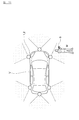
- FIG. 2A is a diagram for describing a first detection method as an example of a method of detecting the position of the operator.
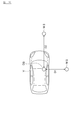
- FIG. 2B is a diagram for describing a second detection method as an example of a method of detecting the position of the operator.
- FIG. 2C is a diagram for explaining a third detection method as an example of the method of detecting the position of the operator.
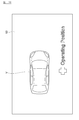
- FIG. 2D is a diagram for describing a fourth detection method as an example of a method of detecting the position of the operator.
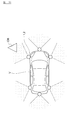
- FIG. 3A is a diagram for describing a first detection method as an example of a method for detecting an obstacle.
- FIG. 3B is a diagram for describing a second detection method as an example of the obstacle detection method.
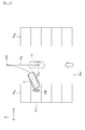
- FIG. 4A is a diagram for explaining the operation of the first rescue mode as an example of the operation of the rescue mode according to the present embodiment.
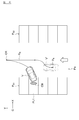
- FIG. 4B is a diagram for describing the operation of the second rescue mode as an example of the operation of the rescue mode according to the present embodiment.
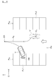
- FIG. 4C is a diagram for explaining the operation of the third rescue mode as an example of the operation of the rescue mode according to the present embodiment.
- FIG. 4D is a diagram for describing an operation of a fourth rescue mode as an example of the operation of the rescue mode according to the present embodiment.
- FIG. 4A is a diagram for explaining the operation of the first rescue mode as an example of the operation of the rescue mode according to the present embodiment.
- FIG. 4B is a diagram for describing the operation of the second rescue mode as an example of the operation of the rescue mode according to the present embodiment.
- FIG. 4C is a diagram for explaining the operation of
- FIG. 4E is a diagram for describing an operation of a fifth rescue mode as an example of the operation of the rescue mode according to the present embodiment.
- FIG. 5 is a flowchart showing an example of the control procedure of the parking control system of the present embodiment.
- FIG. 6 is a flowchart showing an example of the control procedure of the rescue mode according to the present embodiment.
- the parking control device according to the present invention is applied to a parking control system
- a configuration in which the parking control device is mounted on a vehicle is described as an example, but the parking control device is a portable operation terminal (smart phone, PDA: Personal Digital Assistant, etc.) capable of exchanging information with the in-vehicle device. Equipment).
- the parking control method according to the present invention can be used in a parking control device described later.
- FIG. 1 is a block diagram of a parking control system 1000 having a parking control apparatus 100 according to an embodiment of the present invention.
- the parking control system 1000 of the present embodiment includes a camera group 1, a distance measuring device 2, an information server 3, an operation terminal 5, a parking control device 100, and an on-vehicle device 200.
- the in-vehicle device 200 includes a vehicle controller 70, a drive system 40, a steering angle sensor 50, and a vehicle speed sensor 60.
- the parking control apparatus 100 controls an operation of moving (parking) a vehicle to be controlled in a parking space based on an operation command input from the operation terminal 5.
- the camera group 1 includes, for example, cameras 1a to 1d as illustrated.
- the cameras 1a to 1d are respectively installed in the front, the right, the left, and the rear of the vehicle.
- the camera 1a is installed in the front bumper of a vehicle or in the vicinity thereof, captures an image in front of the vehicle, and outputs image information to the parking control device 100.
- the camera 1 b is installed on the right side of the vehicle (for example, the front right side of the vehicle), captures an image on the right side of the vehicle, and outputs image information to the parking control device 100.
- the camera 1 c is installed on the left side of the vehicle (for example, the front left side of the vehicle), captures an image on the left side of the vehicle, and outputs image information to the parking control device 100.
- the camera 1d is installed in the rear bumper of the vehicle or in the vicinity thereof, captures an image of the rear of the vehicle, and outputs image information to the parking control device 100.
- the distance measuring device 2 measures the distance from the vehicle to an object present around the vehicle.
- Examples of the distance measuring device 2 include a radar device such as a millimeter wave radar, a laser radar, and an ultrasonic radar, or a sonar.
- the number of the distance measuring devices 2 is not particularly limited, and may be plural.
- the distance measuring apparatus 2 may be installed at the same position as the cameras 1a to 1d of the camera group 1, or may be installed at different positions. Objects existing around the vehicle include obstacles, pedestrians, and other vehicles.
- the distance measuring device 2 is not limited to the distance to the object, and detects the presence or absence of the object and the position of the object with respect to the vehicle.
- the distance measuring device 2 detects the presence or absence of an object, the distance to the object, and the position of the object, and outputs the detection result to the parking control device 100.
- the information server 3 is an information providing device provided on a communicable network.
- the information server includes a communication device 131 and a storage device 132.
- the storage device 132 includes readable map information 133 and parking lot information 134.
- the map information 133 includes position information of the parking facility.
- the parking lot information 134 includes, for each parking facility, the location of each parking lot (parking lot), an identification number, and location information such as an aisle, a pillar, a wall, a storage space, etc. in the parking facility.
- the parking lot information 134 also includes the passing direction of the vehicle in the passage of the parking facility.
- the parking lot information 134 is not limited to the above information, and may include, for each parking facility, the information of the parking available space as the information of the parking lot where the vehicle can park.
- the parking control device 100 and the operation terminal 5 can access the storage device 132 of the information server 3 to acquire each information.
- the operation terminal 5 is a computer having a portable input function and a communication function that can be brought out of the vehicle.
- Operation terminal 5 receives an input of an operator's operation command for controlling the driving (operation) of the vehicle for parking.
- Driving includes parking (receipt and exit) operations.
- the operator inputs an instruction including an operation instruction for performing parking via the operation terminal 5.
- the operation command includes execution / stop of parking control, selection / change of a target parking position, selection / change of a parking path, and other information necessary for parking.
- the operator can also cause the parking control device 100 to recognize (input) an instruction including an operation instruction by an operator's gesture or the like without using the operation terminal 5.
- the operation terminal 5 includes a communication device, and can exchange information with the parking control device 100 and the information server 3.
- the operation terminal 5 transmits an operation command input outside the vehicle to the parking control device 100 via the communication network, and causes the parking control device 100 to input the operation command.
- the operation terminal 5 communicates with the parking control device 100 using a signal including a unique identification symbol.
- the operation terminal 5 includes a display 53.
- the display 53 presents an input interface and various information. When the display 53 is a touch panel display, it has a function of receiving an operation command.
- the operation terminal 5 receives an input of an operation command used in the parking control method of the present embodiment, and a smartphone such as a smart phone or PDA: Personal Digital Assistant, etc., installed with an application for transmitting the operation command to the parking control apparatus 100. It may be a type of device.
- the vehicle controller 70 is a controller that performs drive control of the vehicle. Examples of the vehicle controller 70 include a computer and an ECU (Electronic Control Unit). The vehicle controller 70 executes the ROM 72 storing the vehicle drive control program and the program stored in the ROM 72 to function as a CPU 71 as an operation circuit functioning as a drive control device and an accessible storage device. And a RAM 73. A target steering angle and a target speed of the vehicle are input to the vehicle controller 70 from the parking control device 100, and a detection value of the steering angle sensor 50 and a detection value of the vehicle speed sensor 60 are input. The vehicle controller 70 controls the operation of the drive system 40 based on the target steering angle and the target speed input to the parking control device 100 when executing control to park the vehicle. Further, the vehicle controller 70 outputs the detection value of the steering angle sensor 50 and the detection value of the vehicle speed sensor 60 to the parking control device 100. The target steering angle and the target speed of the vehicle input from the parking control device 100 will be described later.
- the drive system 40 moves (travels) the vehicle from the current position to the target parking position by driving based on the control command signal acquired from the parking control device 100 via the vehicle controller 70.
- the steering device (shown) of the present embodiment is a drive mechanism that moves the vehicle in the left and right direction.
- Drive system 40 includes an EPS motor.
- the EPS motor acquires a control command signal from the parking control device 100 via the vehicle controller 70.
- the EPS motor drives the power steering mechanism provided in the steering of the steering device based on the acquired control command signal to control the steering amount, and controls the operation when moving the vehicle to the target parking position.
- the control content and operation method of the vehicle for parking are not particularly limited, and methods known at the time of filing can be applied as appropriate.
- the steering angle sensor 50 is installed, for example, inside the steering column, detects the rotation angle of the steering wheel, and outputs a detected value to the parking control device 100 via the vehicle controller 70.
- the vehicle speed sensor 60 calculates, for example, the vehicle speed of the vehicle from the wheel speed detected by a wheel side sensor (shown in the drawing) that detects the number of rotations of the wheel, and outputs a detected value to the parking control device 100 via the vehicle controller 70. Do.
- the parking control device 100 of the present embodiment includes a control device 10, an input device 20, and an output device 30. Each configuration of the parking control device 100 is connected by a CAN (Controller Area Network) or another in-vehicle LAN in order to exchange information with each other.
- the input device 20 includes a communication device 21.
- the communication device 21 receives the operation command transmitted from the external operation terminal 5, and inputs the operation command to the input device 20.
- a subject who inputs an operation command to the external operation terminal 5 may be a human (a user, an occupant, a driver, a worker of a parking facility).
- the input device 20 transmits the received operation command to the control device 10.
- the output device 30 includes a display 31.
- the output device 30 can convey parking control information to the occupant of the vehicle via the display 31.
- the output device 30 can transmit parking control information to the operation terminal 5, and can convey parking control information to the operator of the operation terminal 5 via the display 53 of the operation terminal 5.
- the display 31 of the present embodiment is a touch panel display having an input function and an output function. When the display 31 has an input function, the display 31 functions as the input device 20. Even when the vehicle is controlled based on the operation command input from the operation terminal 5, the occupant can input an operation command such as an emergency stop via the input device 20.
- the control device 10 of the parking control device 100 executes the ROM 12 in which the parking control program is stored and the program stored in the ROM 12 to function as an operation circuit functioning as the parking control device 100 according to the present embodiment.
- It is a computer for parking control provided with CPU11 as, and RAM13 which functions as an accessible storage device.
- the parking control program of the present embodiment is a program for performing parking control to move the vehicle to the target parking position based on the operation command transmitted from the external operation terminal 5.
- the parking control device 100 outputs the target speed and the target steering angle of the vehicle calculated by the program to the vehicle controller 70.
- the vehicle can be moved along the parking path at an appropriate speed for parking at the target parking position by having the vehicle controller 70 operate the drive system 40 according to the target speed and the target steering angle.
- the parking control program of the present embodiment moves the vehicle in a direction away from the target parking position when the vehicle can not park at the target parking position for some reason while moving for parking at the target parking position. It is a program to move.
- the parking control device 100 interrupts the parking control. Then, the parking control device 100 operates the operating terminal 5 to stop the parking control and to select the rescue mode in order to make the operator select whether to shift the control of the vehicle from the parking control to the rescue mode. Send to
- the rescue mode when the vehicle can not park at the target parking position while executing parking control at the target parking position, parking control is interrupted and the vehicle is moved to the predetermined position away from the target parking position. It is a so-called return mode to move. Specific processing after transition to the rescue mode will be described later.
- the operator touches a button on the screen for executing the rescue mode displayed on the screen of the display 53 of the operation terminal 5 an operation command for executing the rescue mode is received via the communication network. Operation command information for causing the rescue mode to be executed is input to the parking control device 100, and the rescue mode program is executed.
- the parking control apparatus 100 of the present embodiment is of a remote control type that sends an operation command from the outside, controls the movement of the vehicle, and parks the vehicle in a predetermined parking space.
- the passenger of the vehicle may be outside the vehicle or may be inside the vehicle.
- the control device 10 of the parking control device 100 performs a target parking frame setting process, a parking start position setting process, a current position estimation process, an operator position detection process, for a vehicle as a function of executing the above-described parking control. It has a function to execute passage recognition processing and parking path generation processing. Further, the control device 10 has a function of executing obstacle detection processing, vehicle passage recognition processing, deceleration processing, operator position detection processing, and rescue route generation processing as functions of executing the above-described rescue mode. Furthermore, the control device 10 executes a path following process and a target speed generating process to move the vehicle along the parking path generated by the parking path generating process or the rescue path generated by the rescue path generating process. It has a function. The rescue route will be described later.
- the above-described respective processes are executed by cooperation of software for realizing the respective processes and the hardware described above. Each processing will be described below.
- Control device 10 sets a parking frame (hereinafter referred to as a target parking frame) for parking the vehicle by automatic driving.
- the control device 10 detects a parking frame present in the parking lot from the captured image captured by the camera group 1.
- the control device 10 generates a bird's-eye view image from the captured image of the camera group 1 and detects a candidate of a frame line constituting the parking frame from the bird's-eye view image.
- the control device 10 determines whether or not the detected frame line candidate satisfies the determination conditions for the interval with another frame line, the relative angle with another frame line, the length, and the like.
- the space divided by the border line candidate satisfying the determination condition of is detected as a parking frame.
- it is not restricted to generating a bird's-eye view image from the captured image of the camera group 1 and detecting a parking frame from the bird's-eye view image, for example, communication with the outside of a car, so-called road-to-vehicle communication, information on parking frame by inter-vehicle communication. You may get
- the automatic driving is that the parking control device 100, not the driver, automatically performs the steering operation, the accelerator operation and the brake operation of the steering device via the vehicle controller 70.
- the parking control device 100 is not limited to a type that automatically performs all of the drive control of the vehicle, and may be a semi-automatic type in which a steering operation is automatically performed and an accelerator and a brake operation are performed. In this case, for example, the driver gets into the vehicle and performs the accelerator / brake operation, and the occupant of the vehicle other than the driver and the worker of the parking facility operate the operation terminal 5.
- the control device 10 detects a parking available space (hereinafter referred to as a parking available space) from the detected parking spaces. For example, based on the distance measurement information (reflection point information) of the distance measurement device 2, the control device 10 has an obstacle such as a parking vehicle in the detected parking frame and the route for parking in the parking frame. Determine if it exists. Then, the control device 10 detects a parking frame in which no obstacle exists as a parking available space. In addition, it is not limited to detecting a parking available space based on distance measurement information of the distance measuring device 2.
- the parking available space may be detected from a captured image of a camera installed in the camera group 1 or a parking lot. . Further, for example, the information server 3 may be accessed to acquire information of the parking available space from the parking lot information 134.
- the control device 10 detects a parking space recommended for the driver and the occupant of the host vehicle (hereinafter referred to as a recommended parking space) from among the available parking spaces and presents the driver and the occupant of the host vehicle. For example, control device 10 transmits information on the recommended parking space to operation terminal 5 and causes display 53 of operation terminal 5 to display the information on the recommended parking space. Further, the control device 10 causes the display 31 of the output device 30 to display information of the recommended parking space.
- the control device 10 sets the parkable space having the shortest required time for parking in each of the parkable spaces as the recommended parking space. Also, for example, the control device 10 sets a parking available space closest to the gaze point of the driver of the host vehicle as a recommended parking space.
- the control device 10 receives specification of the target parking frame by the driver or the occupant of the host vehicle, and sets a target parking position for parking the vehicle.
- the driver or the occupant of the host vehicle touches the recommended parking space displayed on the touch panel display 53 of the operation terminal 5 or moves the display space to the recommended space with the cursor operation keys displayed on the display 53, and the determination button
- a target parking frame can be designated by operating or the like.
- specification of a target parking frame is not restricted to what a person specifies,
- the parking facility side may specify a target parking frame automatically. For example, one recommended parking space designated by the parking facility may be displayed on the display 53 of the operation terminal 5, and the driver or the occupant of the vehicle may designate this recommended parking space.
- the control device 10 sets a target parking position as a position for parking the vehicle.
- Control device 10 sets a position at which parking control is to be started (hereinafter referred to as a parking start position) in order to calculate a parking path described later.
- a parking start position a position at which parking control is to be started
- the current position of the vehicle at that time is set as the parking start position.
- the method of specifying the current position is not particularly limited.
- the control device 10 may access the information server 3 via the antenna 211 and calculate the current position from the map information 133, or GPS (Global Positioning System) The current position of the vehicle may be measured using GPS (Global Positioning System)
- the control device 10 estimates the current position of the vehicle in order to move the vehicle along a parking path or a rescue path described later. For example, the control device 10 measures the current position of the vehicle using GPS, acquires the current position by road-vehicle communication, or calculates the current position based on the steering amount of the steering wheel and the accelerator operation amount. Do.
- Control device 10 detects the position of the operator of operation terminal 5.
- the position of the operator is used to generate a parking path or a rescue path.
- the position of the operator includes information on the position on the movement plane of the vehicle and information on the height position.
- the control device 10 detects the position of the operation terminal 5 possessed by the operator, and calculates the position of the operator based on the position of the operation terminal 5.
- the operation terminal 5 may be provided at a predetermined position or may be possessed by the operator. When the operation terminal 5 is provided at a predetermined position, the operator moves to the installation position of the operation terminal 5 and uses the operation terminal 5. In these cases, the control device 10 can set the position of the operation terminal 5 as the position of the operator.
- FIG. 2A is a diagram for describing detection of the position of the operator M based on detection results of the plurality of distance measuring devices 2 provided in the vehicle V and / or captured images of the camera group 1.
- the control device 10 detects the position of the operator M based on the images captured by the cameras 1a to 1d. Further, the control device 10 detects the two-dimensional position and / or the three-dimensional position of the operator M based on the detection result of the distance measuring device 2.
- FIG. 2B illustrates detection of the position of the operator M holding the operation terminal 5 or the operation terminal 5 based on communication radio waves between the operation terminal 5 and each of the antennas 211 provided at different positions of the vehicle V. It is a figure for.
- the plurality of antennas 211 communicate with one operation terminal 5, the strengths of the radio waves received by the respective antennas 211 are different.
- Control device 10 calculates the position of operation terminal 5 based on the intensity difference of the received radio waves of each antenna 211. Further, the control device 10 calculates the two-dimensional position and / or the three-dimensional position of the operation terminal 5 or the operator M from the intensity difference of the received radio waves of the respective antennas 211.
- FIG. 2C is a diagram for describing designating in advance a predetermined position (direction / distance: D1, D2) as the operation position of the operator M or the installation position of the operation terminal 5 with respect to the driver's seat DS of the vehicle. is there.
- a predetermined position direction / distance: D1, D2
- the control device 10 operates the operator M or the operator for the vehicle V
- the initial position of the operation terminal 5 held by M is calculated.
- FIG. 2D is a diagram for describing display of image information indicating the calculated operation position (the standing position of the operator M: Operation Position) on the display 53 of the operation terminal 5.
- the control device 10 When detecting the position of the operator, the control device 10 causes the display 53 of the operation terminal 5 to display an image as shown in FIG. 2D. Note that this display control may be executed by an application installed on the operation terminal 5 side or may be executed based on an instruction of the control device 10.
- the control device 10 generates a path from the parking start position to the target parking position (hereinafter referred to as a parking path) as a path for parking the vehicle in the target parking frame.
- the shape of the parking path is not particularly limited, and the parking path may be a straight path, a curved path, or a combination thereof.
- the parking path includes a route from the parking start position to the turning position and a route from the turning position to the target parking position.
- the control device 10 calculates, as a parking path, a path obtained by combining a curved path from the parking start position to the turning position and a straight path from the turning position to the target parking position.
- the parking path defined for every parking frame is beforehand memorized in memory (for example, ROM12), and control device 10 uses the parking path from this memory. It may be read out.
- the control device 10 may generate a parking path by acquiring information on a predetermined parking path by road-to-vehicle communication or inter-vehicle communication.
- an intermediate position between the parking start position and the target parking position is set to generate a parking path from the parking start position to the intermediate position, and when the intermediate position is approached, parking from the intermediate position to the target parking position It is also possible to generate a route.
- the parking path can be regenerated and changed during control.
- Control device 10 detects an obstacle existing outside the vehicle. Obstacles include parking lot walls, pillars and other structures, installations around vehicles, pedestrians, other vehicles, parked vehicles and the like.
- FIG. 3A is a diagram for describing detection of an obstacle OB present around the vehicle V.
- the control apparatus 10 detects the obstruction OB based on the captured image of the camera group 1 as a detection result of several ranging apparatus 2 provided in the vehicle.
- the detection result of the distance measuring device 2 includes the presence or absence of the obstacle OB, the position of the obstacle OB, the size of the obstacle OB, and the distance to the obstacle OB.
- the control device 10 performs image processing on the captured image captured by each of the cameras 1a to 1d to obtain the presence or absence of the obstacle OB, the position of the obstacle OB, the size of the obstacle OB, and the obstacle OB. Detect the distance to Note that the detection of an obstacle is not limited to the above-described method, and may be performed using, for example, a motion stereo technique with the cameras 1a to 1d.
- FIG. 3B is a view for explaining a method of detecting an obstacle including a structure such as a wall of a parking lot and a pillar.
- the control device 10 accesses the storage device 132 of the information server 3 to acquire the parking lot information 134. Since the parking lot information 134 includes information of a structure such as a wall of a parking lot and a pillar, the control device 10 detects an obstacle including a structure based on the parking lot information 134.
- a specific floor map MP of the temporary parking lot ST is shown as the parking lot information 134, and in the floor map MP, for example, the position of each parking lot PL is indicated by X coordinates and Y coordinates.
- the detection result by the obstacle detection process is used as a trigger for shifting from the parking control to the rescue mode
- the present invention is not limited to this.
- the control device 10 can continuously acquire the detection result of the obstacle and use the detection result for other processing.
- the control device 10 may use the detection result of the obstacle in the process of setting the target parking position, may use the detection result of the obstacle in the process of calculating the parking route, or rescue described later
- the detection result of the obstacle may be used in the process of calculating the route.
- the control device 10 recognizes the passage for the vehicle in the parking facility. Specifically, the control device 10 detects the presence or absence of the passage for the vehicle and the passing direction of the passage for the vehicle.
- the passage for vehicles is a passage for vehicles to move a parking facility, and is a passage adjacent to each parking lot (also referred to as a parking frame) provided in the parking facility.
- a vehicle moves into a parking lot by moving from a passage for vehicles toward a parking lot and parks. On the contrary, the vehicle leaves the parking lot by starting (advancing or reversing) from the parking lot to the passage for the vehicle.
- the passage for vehicles includes information of either one-way or two-way passage, for example, according to the passage rule of the parking facility, the passage for vehicles is one-way
- the passage direction of the passage for vehicles can be defined as from north to south.
- regulating the passage direction of the passage for vehicles is not specifically limited to the method of using north, south, east, west.
- the passage direction of the passage for vehicles may be defined as left-hand traffic or right-hand traffic.
- the map of the parking facility can be acquired, the information on the passing direction of the passage for the vehicle included in the map information can be used.
- a method of recognizing a passage for a vehicle will be described.
- the control device 10 acquires the map of the parking facility from the memory, and for a plurality of vehicles provided in the parking facility.
- the passage direction of the passage is detected for each passage.
- the control device 10 accesses the storage device 132 of the information server 3 to acquire the parking lot information 134.
- the parking lot information 134 includes, as information indicating the moving direction of the vehicle at the parking facility, information on the passing direction of the passage for the vehicle.
- the control device 10 recognizes a passage for a vehicle based on the parking lot information 134.
- a specific floor map MP of the temporary parking lot ST is shown as the parking lot information 134, and in the floor map MP, information on whether the aisle for the vehicle is facing or one-way passing is shown. It contains information on the direction of travel for each aisle.
- the method of recognizing the passage for the vehicle is not limited to the method of acquiring information stored in advance in the memory such as the ROM 12 or the memory or the information server 3, and the control device 10 can , Can recognize the passage for the vehicle.
- the control device 10 recognizes the passing direction of the passage for the vehicle by detecting a symbol indicating the moving direction of the vehicle drawn in the passage for the vehicle, a white line, or the like from the captured image of the camera group 1 be able to. Further, when the guidance display board indicating the moving direction of the vehicle is included in the captured image, the control device 10 can detect the passage of the vehicle and the passing direction of the passage.
- the control device 10 detects an obstacle while the vehicle is moving along the parking path toward the target parking position, the control device 10 forcibly decelerates the vehicle to prevent the obstacle from coming into contact with the vehicle. Stop it. For example, even in the case where the target speed gradually decelerates as the target speed approaches the target parking position in the parking control, the control device 10 forcibly stops the vehicle by increasing the rate of deceleration. In addition, the control device 10 stops the vehicle even if the parking path includes the turning position and the obstacle is detected while the vehicle is moving toward the turning position.
- the rescue route is a route for moving the vehicle away from the target parking position when shifting to the rescue mode.
- the control device 10 evacuates as a movement route from the position where the vehicle stopped to the target position (hereinafter referred to as the rescue position) where the vehicle is moving.
- Generate a route (hereinafter referred to as a rescue route).
- the passage for the vehicle adjacent to the target parking position is a passage for the vehicle provided in a direction in which the vehicle can enter and exit from the target parking position based on the target parking position.
- the shape of the rescue route is not particularly limited, and the rescue route may be a linear route, a curved route, or a combination of them.
- the control device 10 generates a rescue route that allows the vehicle to move safely to the rescue position in consideration of the detection result of the obstacle and the position information of the operator. Specific examples of the rescue route will be described later.
- control device 10 calculates a target steering angle and a target speed in order to move the vehicle along these paths.
- Control device 10 outputs the calculated target steering angle and target speed to vehicle controller 70.
- the control device 10 forcibly decelerates the target speed by deceleration processing.
- the method of calculating the target steering angle and the target speed is not particularly limited, and any method known at the time of filing can be applied as appropriate.
- FIGS. 4A to 4E are diagrams showing an example of the operation in the rescue mode.
- FIGS. 4A to 4E show a scene in which the obstacle OB is detected while the parking control device 100 executes the parking control for parking the vehicle V backward in the parking lot PL1.
- the control device 10 determines that the vehicle V can not be parked in the parking lot PL1 and shifts to the rescue mode to make the operator of the operation terminal 5 select whether to shift to the rescue mode.
- the display 53 of the operation terminal 5 is made to present possible information. It is assumed that the operator selects the rescue mode and presses the determination button of the operation terminal 5.
- parking group P G1 is composed of a plurality of parking including parking PL1, each parking are adjacent to each other.
- parking group P G2 is the parking group P G1 on the opposite side across the passage Pa for a vehicle, is provided to face the parking group P G1.
- a parked vehicle exists in the parking lot PL1, when the vehicle starts (forwards or reverses) from the parking lot PL1, it exits the passage Pa for the vehicle.
- a parked vehicle exists in a parking lot configuring the parking lot group PG2 , when the vehicle starts (forwards or reverses) from the parking lot, it exits the passage Pa for the vehicle.
- the control device 10 when shifting to the rescue mode, first, the control device 10 recognizes the passage Pa for the vehicle. In the example of FIG. 4A, the control device 10 detects that the passage Pa for the vehicle is one-way and that the passage direction of the passage Pa for the vehicle is a positive direction along the y axis. For example, the control device 10 recognizes the passage Pa for the vehicle based on the information of the parking facility stored in advance in the memory.
- the control device 10 is located at a position where the traveling direction of the vehicle V is substantially parallel to the passing direction (y-axis positive direction) of the passage Pa for the vehicle, and the rescue position P R is at a position on the passage Pa for the vehicle.
- Set Control device 10 generates rescue route R R from the current position of vehicle V to rescue position P R.
- the controller 10 generates a path which the vehicle V reaches the turn-back position CR turn left while advancing, the path which the vehicle V is in reverse from the crosscut position CR reaches the rescue position P R .
- the control device 10 calculates a target steering angle and a target speed for moving the vehicle V along the rescue route R R to the rescue position P R and outputs the target steering angle and the target speed to the vehicle controller 70.
- the direction in which the vehicle V moves along the rescue route R R to the rescue position P R is the movement direction.
- the movement direction also includes the traveling direction in which the vehicle V advances when the vehicle V completes the movement along the rescue route R R to the rescue position P R.
- Vehicle V by moving to the rescue position P R, can be retracted from the obstacle OB and parking PL1.
- a result of the vehicle V has moved to the rescue position P R, and shows a state in which the front is stopped facing in a direction along the passing direction of the passage Pa for a vehicle as the vehicle V '.
- the vehicle V moves to a place away from the obstacle OB and the parking lot PL1 by the vehicle controller 70, and stops with the traveling direction along the passing direction of the passage Pa for the vehicle.
- the rescue route R R includes the turning position CR, but the rescue route R R is not limited to including the turning position CR.
- the route to the position CR may be the rescue route R R.
- FIG. 4B differs from FIG. 4A in that the passage Pa for a vehicle is facing traffic as compared to the passage Pa for a vehicle shown in FIG. 4A.
- the passage Pa for the vehicle is configured by two passages of the passage Pa1 for the vehicle and the passage Pa2 for the vehicle, with the boundary line B interposed therebetween.
- the passage Pa for vehicles is on the left.
- the passing direction of the passage Pa1 for a vehicle is a positive direction along the y axis
- the passing direction of the passage Pa2 for a vehicle is a negative direction along the y axis.
- parking group P G1 is adjacent to the passage Pa1 for vehicles
- parking group P G2 is adjacent the path Pa2 for a vehicle.
- the control device 10 when shifting to the rescue mode, first, the control device 10 recognizes the passage Pa for the vehicle. In the example of FIG. 4B, the control device 10 detects that the passage Pa for the vehicle is a facing traffic and a left traffic. Specifically, in the control device 10, the passage direction of the passage Pa1 for a vehicle is a positive direction along the y axis, and the passage direction of the passage Pa2 for a vehicle is a negative direction along the y axis To detect Further, the control device 10 detects that the route for the vehicle adjacent to the parking lot PL1 which is the target parking position is the passage Pa1 for the vehicle.
- the control device 10 recognizes the passage Pa for the vehicle based on the information of the parking facility stored in advance in the memory, and among the passages Pa for the vehicle, the side adjacent to the target parking lot PL1 is the passage for the vehicle Recognize that it is Pa1. Also, if the aisle width is a passable width (for example, 6 m or more), according to the traffic rule of the country, for example, in the case of left-hand traffic, as shown in FIG. It may be determined that the passing direction of the passage Pa1 is positive along the y axis, and that the passing direction of the passage Pa2 for the vehicle is negative along the y axis. Further, an indication (paint of arrow) indicating the passing direction may be detected on the road surface of the passage Pa1 for the vehicle to recognize the passing direction.
- a passable width for example, 6 m or more
- And control device 10 is a position where the traveling direction of vehicle V becomes approximately parallel to the passing direction (y-axis positive direction) of passage Pa1 for vehicles, and the rescue position P R is at the position on passage Pa for vehicles.
- Set Control device 10 generates rescue route R R from the current position of vehicle V to rescue position P R.
- the control device 10 turns to the left while the vehicle V advances, a route to reach the turning position CR, a route to reverse the vehicle V from the turning position CR, and to reach a predetermined position; Generates a path approaching the passage Pa1 side for the vehicle while moving backward from the predetermined position.
- Vehicle V is driven by control vehicle controller 70 executes, by moving to the rescue position P R, can be retracted from the obstacle OB and parking PL1.
- the direction in which the vehicle V moves along the rescue route R R to the rescue position P R is the movement direction.
- the moving direction also includes the advancing direction in which the vehicle V advances when the vehicle V completes moving along the rescue route R R to the rescue position P R. Further, the moving direction also includes the traveling direction of the vehicle out of the parking space and heading for the turning position CR.
- the result of the vehicle V has moved to the rescue position P R, and shows a state in which the front of the vehicle V is stopped facing the direction along the passage direction of the passages Pa1 for a vehicle as the vehicle V '.
- the vehicle V moves to a location away from the obstacle OB and the parking lot PL1 by the vehicle controller 70, and stops with the traveling direction along the passing direction of the passage Pa1 for the vehicle.
- the vehicle V ' moves and stops in a state in which the traveling direction is opposite to the passing direction of the passage Pa2 for the vehicle, and the passage of the passage Pa for the vehicle is blocked while the vehicle V ' is moving and stopped.
- Can prevent when the operator of operation terminal 5 rides on vehicle V ′ and drives, the operator advances the passage Pa1 for vehicle without changing the direction of the vehicle V ′ and performs the next parking It is possible to move to the space available.
- FIG. 4C is a scene similar to the scene shown in FIG. 4A, the same symbols as those in FIG. 4A are attached, and the description thereof is used. Another example of the rescue mode operation will be described with reference to FIG. 4C. Also in the example of FIG. 4C, as in the example of FIG. 4A, when shifting to the rescue mode, the control device 10 first recognizes the passage Pa for the vehicle. The control device 10 detects that the passage Pa for the vehicle is one way and that the passage direction of the passage Pa for the vehicle is a positive direction along the y axis.
- the control device 10 is located at a position where the traveling direction of the vehicle V is substantially parallel to the passing direction (y-axis positive direction) of the passage Pa for the vehicle, and the rescue position P R is at a position on the passage Pa for the vehicle.
- the control unit 10 in the width direction of the passage Pa for a vehicle (x-axis direction), and sets the rescue position P R in the parking lot PL1 side.
- Control device 10 generates rescue route R R from the current position of vehicle V to rescue position P R.
- FIG. 4C the control unit 10 in the width direction of the passage Pa for a vehicle (x-axis direction)
- the control device 10 turns to the left while the vehicle V is moving forward, reaches the turning position CR, and moves backward from the turning position CR to reach a predetermined position, and the vehicle V Generates a path approaching the parking lot PL1 while moving backward from the predetermined position.
- Vehicle V is driven by control vehicle controller 70 executes, by moving to the rescue position P R, can be retracted from the obstacle OB and parking PL1.
- the direction in which the vehicle V moves along the rescue route R R to the rescue position P R is the movement direction.
- the moving direction also includes the advancing direction in which the vehicle V advances when the vehicle V completes moving along the rescue route R R to the rescue position P R.
- the moving direction also includes the traveling direction of the vehicle out of the parking space and heading for the turning position CR.
- the results of the vehicle V has moved to the rescue position P R, together with the front of the vehicle V are in the direction along the passage direction of the passages Pa for vehicles, parking in the width direction of the passage Pa for vehicles
- the stopped state on the PL1 side is shown as a vehicle V ′ .
- the vehicle V moves to a place away from the obstacle OB and the parking lot PL1 by the vehicle controller 70, and stops with the traveling direction along the passing direction of the passage Pa for the vehicle.
- the vehicle stops at the parking lot PL1 side, which is the initial target parking position, in the width direction of the passage Pa for the vehicle.
- the direction in which the vehicle V moves along the rescue route R R to the rescue position P R is the movement direction.
- the moving direction also includes the advancing direction in which the vehicle V advances when the vehicle V completes moving along the rescue route R R to the rescue position P R.
- the moving direction also includes the traveling direction of the vehicle out of the parking space and heading for the turning position CR. Further, 'when driving riding, the operator of the vehicle V' operation by the operator terminal 5 the vehicle V in rescue position P R without the driving operation for changing the direction of the, as it advances the passage Pa for vehicles You can move to the next available parking space.
- FIG. 4D is a scene similar to the scene shown in FIG. 4A, the same symbols as those in FIG. 4A are attached and the description thereof is used. Another example of the rescue mode operation will be described with reference to FIG. 4D. Also in the example of FIG. 4D, as in the example of FIG. 4A, when shifting to the rescue mode, the control device 10 first recognizes the passage Pa for the vehicle. The control device 10 detects that the passage Pa for the vehicle is one way and that the passage direction of the passage Pa for the vehicle is a positive direction along the y axis.
- the control device 10 is located at a position where the traveling direction of the vehicle V is substantially parallel to the passing direction (y-axis positive direction) of the passage Pa for the vehicle, and the rescue position P R is at a position on the passage Pa for the vehicle.
- the control unit 10 in the width direction of the passage Pa for a vehicle (x-axis direction), and sets the rescue position P R in the parking lot PL2 side which is the next target parking position.
- Control device 10 generates rescue route R R from the current position of vehicle V to rescue position P R.
- FIG. 4D the control unit 10 in the width direction of the passage Pa for a vehicle (x-axis direction)
- the control device 10 turns the vehicle V to the left while turning forward to the turning position CR, and the vehicle V moves backward from the turning position CR to the predetermined position, and the vehicle V Generates a route approaching the parking lot PL2 while moving backward from the predetermined position.
- Vehicle V is driven by control vehicle controller 70 executes, by moving to the rescue position P R, can be retracted from the obstacle OB and parking PL1.
- a result of the vehicle V has moved to the rescue position P R, forward with facing direction along the passing direction of the passage Pa for a vehicle, the parking PL2 side in the width direction of the passage Pa for vehicles
- the stopped state is shown as a vehicle V ' .
- the control device 10 sets the next target parking position with reference to the execution result of the target parking frame setting process.
- the control device 10 selects the next available parking space from among the available parking spaces not selected as the recommended parking space, when a plurality of available parking spaces are detected in the process of the target parking frame setting process.
- the control device 10 sets the next target parking position based on the next available parking space.
- the control device 10 sets the parkable space closest to the current position of the stopped vehicle as the next parkable space.
- control device 10 sets a parking available space having the shortest required time for parking as the next parking available space, taking into consideration not only the current position but also the direction of the vehicle.
- the timing for detecting the next target parking position is not particularly limited, and may be before the vehicle V detects the obstacle OB or may be after transition to the rescue mode.
- the vehicle V moves to a place away from the obstacle OB and the parking lot PL1 by the vehicle controller 70, and stops with the traveling direction along the passing direction of the passage Pa for the vehicle. In addition, it stops on the parking lot PL2 side which is the next target parking position in the width direction of the passage Pa for vehicles. As a result, the vehicle V stops at a position relatively close to the next target parking position, so that the operator of the operation terminal 5 can smoothly perform the next parking control by driving or remote control.
- FIG. 4E is a scene similar to the scene shown to FIG. 4A, the same symbol as FIG. 4A is attached and the description is used. Another rescue operation example will be described with reference to FIG. 4E. Also in the example of FIG. 4E, as in the example of FIG. 4A, when shifting to the rescue mode, first, the control device 10 recognizes the passage Pa for the vehicle. The control device 10 detects that the passage Pa for the vehicle is one way and that the passage direction of the passage Pa for the vehicle is a positive direction along the y axis.
- the control device 10 is located at a position where the traveling direction of the vehicle V is substantially parallel to the passing direction (y-axis positive direction) of the passage Pa for the vehicle, and the rescue position P R is at a position on the passage Pa for the vehicle.
- the control unit 10 in the width direction of the passage Pa for a vehicle (x-axis direction) the operator M sets the rescue position P R on the side position.
- Control device 10 generates rescue route R R from the current position of vehicle V to rescue position P R.
- FIG. 4E the control unit 10 in the width direction of the passage Pa for a vehicle (x-axis direction)
- the control device 10 turns to the left while the vehicle V is moving forward, reaches the turning position CR, and moves backward the vehicle V from the turning position CR to reach a predetermined position, and the vehicle V Generates a path approaching the operator M while moving backward from the predetermined position.
- Vehicle V is driven by control vehicle controller 70 executes, by moving to the rescue position P R, can be retracted from the obstacle OB and parking PL1.
- the front turns to a direction along the passing direction of the passage Pa for the vehicle and to the operator M side in the width direction of the passage Pa for the vehicle
- the stopped state is shown as a vehicle V ' .
- the control device 10 uses, as a method for detecting the position of the operator M, any one of the methods described with reference to FIGS. 2A to 2C or a combination of these methods. Further, the timing of detecting the operator M is not particularly limited, and may be before the vehicle V detects the obstacle OB or after transition to the rescue mode.
- the vehicle V moves to a place away from the obstacle OB and the parking lot PL1 by the vehicle controller 70, and stops with the traveling direction along the passing direction of the passage Pa for the vehicle. Moreover, it stops on the operator M side in the width direction of the passage Pa for vehicles. Thus, the operator M can easily get in the vehicle V. Further, the operator M can move forward to the next passage Pa for the next parking available space without performing the driving operation for changing the direction of the vehicle V ′ .
- FIG. 5 is a flowchart showing a control procedure of the parking control process performed by the parking control system 1000 according to the present embodiment.
- the start trigger of the parking control process is not particularly limited, and may be triggered by the operation of the start switch of the parking control device 100.
- step S101 the control device 10 of the parking control device 100 acquires information around the vehicle.
- the control device 10 acquires distance measurement signals from the distance measurement devices 2 attached to a plurality of locations of the vehicle, as necessary. Further, the control device 10 acquires captured images captured by the cameras 1a to 1d attached to a plurality of locations of the vehicle, as necessary. Note that the acquisition of the distance measurement signal from the distance measuring device 2 and the acquisition of the captured image from the camera group 1 may be performed alternatively.
- step S102 the control device 10 detects a parking available space.
- the control device 10 detects a frame (area) of the parking space based on the images captured by the cameras 1a to 1d.
- the control device 10 detects a vacant parking space by using detection data of the distance measuring device 2 and detection data extracted from the captured image.
- the control device 10 detects, among the parking spaces, a parking space which is empty (other vehicles are not parked) and whose route for completing the parking can be calculated as the parking available space.
- being able to calculate the parking path means that the path of the path from the current position to the target parking position can be drawn on the road surface coordinates without interference with an obstacle (including a parked vehicle).
- step S103 the control device 10 recognizes a passage for a vehicle.
- the control device 10 acquires information of a parking facility stored in advance in a memory such as the ROM 12, or accesses the information server 3 to acquire the parking lot information 134 stored in the storage device 132. By doing this, it is possible to recognize the passage for the vehicle provided in the parking facility.
- the control device 10 detects, with respect to the parkable space detected in step S102, whether the passage for the vehicle adjacent to the start side is one-way or face-to-face. In the case of face-to-face traffic, the control device 10 detects which one of the parking spaces and the aisles adjacent to the vehicle are. The control device 10 also detects the passing direction of the passage for the vehicle.
- step S104 the control device 10 transmits the parking available space to the operation terminal 5, causes the display 53 of the operation terminal 5 to display, and requests the operator to input the selection information of the target parking position for parking the vehicle.
- the target parking position may be automatically selected by the control device 10 or the parking facility side.
- the parking available space is set as a target parking position.
- the operator gets off the vehicle and performs so-called remote parking processing to park the vehicle from the outside.
- step S105 the operator of the operation terminal 5 and the occupants of other vehicles get off.
- the operator who has got out of the vehicle inputs operation information on the parking process into the operation terminal 5.
- the operation information at least includes an instruction to start the parking process.
- the operation information is sent to the control device 10.
- step S106 the control device 10 detects the position of the operator.
- the control device 10 detects the position of the operator, for example, by the method described with reference to FIGS. 2A to 2C. For example, when the operator is detected from the captured image of the camera group 1 or the detection data of the distance measuring device 2, the control device 10 detects the relative position of the operator with respect to the vehicle.
- step S107 the control device 10 calculates a parking path leading to the target parking position.
- the parking path includes the turning position necessary to move to the parking available space.
- the parking path is defined as a line and is defined as a band-like area according to the occupied area of the vehicle according to the vehicle width.
- the occupied area of the vehicle is defined in consideration of the vehicle width and the allowance width secured for movement.
- the control device 10 generates a control command to move the vehicle along the calculated parking path.
- the control device 10 causes the display 53 of the operation terminal 5 to display the parking path, and urges the operator to confirm.
- step S108 when the operator confirms the parking path and inputs an execution command to the operation terminal 5, the control device 10 starts the execution of the parking control.
- the vehicle starts moving along the parking path toward the target parking position.
- step S109 the control device 10 determines whether an obstacle is detected on the parking path or in the vicinity of the parking path.
- the control device 10 continuously acquires a captured image of the camera group 1 and detection data of the distance measuring device 2 and determines whether or not an obstacle exists around the vehicle. If an obstacle is detected, it will progress to step S110, and if an obstacle is not detected, it will progress to step S113.
- step S110 the control device 10 stops the vehicle in order to avoid contact between the vehicle and the obstacle.
- control device 10 acquires the distance from the vehicle to the obstacle detected in step S109, and calculates the target velocity deceleration according to the acquired distance. Then, the control device 10 forcibly decelerates the target speed to stop the vehicle.
- step S111 the control device 10 causes the display 53 of the operation terminal 5 to present information capable of shifting to the rescue mode in order to make the operator select whether to shift to the rescue mode.
- the display 53 displays information that the vehicle has stopped due to the detection of an obstacle, and information that can shift to the rescue mode, and the operator shifts to the rescue mode by selecting the rescue mode and operating the determination button. can do. If it transfers to rescue mode, it will progress to step S112, and conversely, if it does not shift to rescue mode, it will progress to step S113.
- step S112 the control device 10 starts control for separating the vehicle stopped in step S110 from the obstacle and the target parking position. The operation after transition to the rescue mode will be described later.
- step S113 the control device 10 determines whether the vehicle has reached the turning position. For example, the control device 10 performs determination by comparing the current position of the vehicle with the switching position. If it is determined that the vehicle has reached the turning position, the process proceeds to step S114. Conversely, if it is determined that the vehicle has not reached the turning position, the process returns to step S109.
- step S114 the control device 10 executes the shift change included in the control command. Thereafter, the control device 10 completes the parking control by continuously executing the control command in step S115. If the parking path calculated in step S107 does not include the switching position, steps S113 and S114 may be omitted.
- control device 10 recognizes the passage for the vehicle in step S116.
- the method of recognizing a passage for a vehicle may be the same as or different from the method of recognition in step S103 shown in FIG.
- control device 10 recognizes a passage for a vehicle adjacent to the target parking position set in step S104 shown in FIG. 5 in the direction in which the vehicle is delivered.
- the control device 10 detects whether the passage for the vehicle is one-way or face-to-face and the passing direction of the passage for the vehicle. In the case of face-to-face traffic, the control device 10 detects which of the target parking position and the passage for the adjacent vehicle are.
- control device 10 calculates the moving direction of the vehicle. Specifically, the control device 10 sets the rescue position based on the traveling direction of the passage for the vehicle, and calculates the rescue route leading to the rescue position. First, the control device 10 sets the rescue position. For example, as in the example of FIG. 4A, the control device 10 sets the rescue position at a position on the passage for the vehicle at a position where the traveling direction of the vehicle is substantially parallel to the passing direction of the passage for the vehicle. . In addition, when the passage for the vehicle is a facing traffic, as in the example of FIG. 4B, the control device 10 passes the passage on the side of the passage for the vehicle adjacent to the target parking position among the passages for the vehicle.
- a rescue position is set at a position substantially parallel to the direction and on this passage.
- the control device 10 may adjust the rescue position in the width direction of the passage for the vehicle. For example, as in the example of FIG. 4C, the control device 10 may set the rescue position on the side of the initial target parking position in the width direction of the passage for the vehicle. Also, for example, as in the example of FIG. 4D, the control device 10 may set the rescue position on the side of the next target parking position in the width direction of the passage for the vehicle. Further, for example, the control device 10 may set the rescue position on the operator side in the width direction of the passage for the vehicle as in the example of FIG. 4E.
- the control device 10 calculates the moving direction of the vehicle by generating a rescue route from the current position to the set rescue position.
- the control device 10 calculates the rescue route R R so as to stop in a state in which the traveling direction is substantially parallel to the traveling direction of the passage Pa for the vehicle.
- step S118 when the operator confirms the rescue route and inputs an execution command to the operation terminal 5, the control device 10 starts the execution of the rescue control.
- the vehicle starts moving along the rescue route toward the rescue position.
- step S119 the control device 10 determines whether the vehicle has reached the switchback position. If it is determined that the vehicle has reached the turning position, the process proceeds to step S120, and in step S120, the control device 10 executes the shift change included in the control command. Conversely, if it is determined that the vehicle has not reached the turnaround position, the process waits in step S119 until the turnaround position is reached.
- step S121 when the vehicle reaches the rescue position along the rescue path, in step S122, the control device 10 stops the vehicle and ends the parking control process.
- the passing direction of the passage for the vehicle adjacent to the target parking position Calculate the rescue route based on and move the vehicle along the rescue route.
- the direction of travel of the vehicle in the passage for the vehicle is a position along the passage direction of the passage for the vehicle
- the rescue position is at a position on the passage for the vehicle.
- the vehicle is moved along a rescue route that ends at the rescue position.
- the vehicle can be prevented from obstructing passage, for example, when the vehicle stops in a state in which the vehicle runs in the direction opposite to the passage direction of the passage for the vehicle.
- the rescue position on the target parking position side in the width direction of the vehicle passage Set and move the vehicle along a rescue route that ends at the rescue position.
- the vehicle stopped near the target parking position is moved to the target parking position in the width direction of the passage for the vehicle, so that the vehicle can be retracted from the target parking position by a relatively short moving distance.
- the next target parking position is specified, and the width direction of the passage for the vehicle
- the rescue position is set on the next target parking position side, and the vehicle is moved along the rescue route ending at the rescue position.
- the vehicle is parked smoothly to the next target parking position by driving or remote control in order to move the vehicle having the vehicle stopped near the target parking position to the next target parking position side in the width direction of the passage for the vehicle be able to.
- the parking control to the target parking position is interrupted and the vehicle leaves the target parking position
- the position of the operator is detected, and in the width direction of the passage for the vehicle.
- the rescue position is set on the side where the operator is located, and the vehicle is moved along a rescue route ending at the rescue position.
- the vehicle stops at a position relatively close to the operator, so that the operator can get into the vehicle.
- the control device 10 detects the parked vehicle from the captured image of the camera group 1 and recognizes the passage for the vehicle from the arrangement of the parked vehicles. May be For example, the control device 10 may identify the passage for the vehicle from the direction along the front or rear of the plurality of parked vehicles. This can improve the accuracy of identifying the passage for the vehicle.
- the present invention has been described by taking the case where the rescue position is set at a position where the traveling direction is substantially parallel to the passing direction of the passage for vehicles.
- the rescue position is set so that the traveling direction is substantially parallel to the passing direction of the passage for the vehicle, and the rescue position is made the end point.
- a rescue route may be generated.
Landscapes
- Engineering & Computer Science (AREA)
- General Physics & Mathematics (AREA)
- Physics & Mathematics (AREA)
- Mechanical Engineering (AREA)
- Automation & Control Theory (AREA)
- Transportation (AREA)
- Radar, Positioning & Navigation (AREA)
- Aviation & Aerospace Engineering (AREA)
- Remote Sensing (AREA)
- Theoretical Computer Science (AREA)
- Multimedia (AREA)
- Traffic Control Systems (AREA)
- Control Of Driving Devices And Active Controlling Of Vehicle (AREA)
Abstract
Description
本実施形態では、本発明に係る駐車制御装置を、駐車制御システムに適用した場合を例にして説明する。本実施形態では、駐車制御装置を車両に搭載する構成を例に説明するが、駐車制御装置は、車載装置と情報の授受が可能な可搬の操作端末(スマートフォン、PDA:Personal Digital Assistantなどの機器)に適用してもよい。また、本発明に係る駐車制御方法は後述する駐車制御装置において使用できる。
100…駐車制御装置
10…制御装置
11…CPU
12…ROM
13…RAM
20…入力装置
21…通信装置
211…アンテナ
30…出力装置
31…ディスプレイ
1a~1d…カメラ
2…測距装置
3…情報サーバ
131…通信装置
132…記憶装置
133…地図情報
134…駐車場情報
5…操作端末
51…通信装置
511…アンテナ
52…入力装置
53…ディスプレイ
200…車載装置
40…駆動システム
50…操舵角センサ
60…車速センサ
70…車両コントローラ
71…CPU
72…ROM
73…RAM
Claims (6)
- 車両の外の操作者から取得した操作指令に基づき、前記車両を目標駐車位置に移動させる駐車制御を行い、
前記目標駐車位置への前記駐車制御を中断して、前記車両が前記目標駐車位置から離れる場合、前記目標駐車位置に隣接する車両用の通路の通行方向に基づいて、前記車両の移動方向を算出し、
前記移動方向へ前記車両を移動させる駐車制御方法。 - 前記通路での前記車両の進行方向が前記通行方向に沿うように前記車両を移動させる請求項1に記載の駐車制御方法。
- 前記通路の幅方向において前記目標駐車位置側に前記車両を移動させる請求項1又は2に記載の駐車制御方法。
- 次の前記目標駐車位置を特定し、
前記通路の幅方向において前記次の目標駐車位置側に前記車両を移動させる請求項1~3の何れか一項に記載の駐車制御方法。 - 前記操作者の位置を検出し、
前記通路の幅方向において前記操作者側に前記車両を移動させる請求項1~4の何れか一項に記載の駐車制御方法。 - 車両の外の操作者から取得した操作指令に基づき、前記車両を目標駐車位置に移動させる駐車制御を行う制御装置を備え、
前記制御装置は、
前記目標駐車位置への前記駐車制御を中断して、前記車両が前記目標駐車位置から離れる場合、前記目標駐車位置に隣接する車両用の通路の通行方向に基づいて、前記車両の移動方向を算出し、
前記移動方向へ前記車両を移動させる駐車制御装置。
Priority Applications (6)
| Application Number | Priority Date | Filing Date | Title |
|---|---|---|---|
| US16/954,860 US20210086759A1 (en) | 2017-12-20 | 2017-12-20 | Parking Control Method and Parking Control Apparatus |
| RU2020123684A RU2746684C1 (ru) | 2017-12-20 | 2017-12-20 | Способ управления парковкой и оборудование управления парковкой |
| EP17935514.4A EP3730352A4 (en) | 2017-12-20 | 2017-12-20 | PARKING CONTROL PROCESS AND PARKING CONTROL DEVICE |
| PCT/JP2017/045819 WO2019123587A1 (ja) | 2017-12-20 | 2017-12-20 | 駐車制御方法及び駐車制御装置 |
| JP2019559947A JP6927330B2 (ja) | 2017-12-20 | 2017-12-20 | 駐車制御方法及び駐車制御装置 |
| CN201780097856.7A CN111527010A (zh) | 2017-12-20 | 2017-12-20 | 驻车控制方法以及驻车控制装置 |
Applications Claiming Priority (1)
| Application Number | Priority Date | Filing Date | Title |
|---|---|---|---|
| PCT/JP2017/045819 WO2019123587A1 (ja) | 2017-12-20 | 2017-12-20 | 駐車制御方法及び駐車制御装置 |
Publications (1)
| Publication Number | Publication Date |
|---|---|
| WO2019123587A1 true WO2019123587A1 (ja) | 2019-06-27 |
Family
ID=66993205
Family Applications (1)
| Application Number | Title | Priority Date | Filing Date |
|---|---|---|---|
| PCT/JP2017/045819 Ceased WO2019123587A1 (ja) | 2017-12-20 | 2017-12-20 | 駐車制御方法及び駐車制御装置 |
Country Status (6)
| Country | Link |
|---|---|
| US (1) | US20210086759A1 (ja) |
| EP (1) | EP3730352A4 (ja) |
| JP (1) | JP6927330B2 (ja) |
| CN (1) | CN111527010A (ja) |
| RU (1) | RU2746684C1 (ja) |
| WO (1) | WO2019123587A1 (ja) |
Cited By (5)
| Publication number | Priority date | Publication date | Assignee | Title |
|---|---|---|---|---|
| CN112208518A (zh) * | 2020-09-28 | 2021-01-12 | 惠州华阳通用电子有限公司 | 一种泊车路径自动规划方法 |
| JP2021062754A (ja) * | 2019-10-15 | 2021-04-22 | アイシン精機株式会社 | 駐車支援装置、駐車支援方法、およびプログラム |
| JP2021126978A (ja) * | 2020-02-13 | 2021-09-02 | フォルシアクラリオン・エレクトロニクス株式会社 | 駐車支援装置、駐車支援システム及び駐車支援方法 |
| JP2022134954A (ja) * | 2021-03-04 | 2022-09-15 | スズキ株式会社 | 自動駐車装置 |
| JP2024525309A (ja) * | 2021-06-08 | 2024-07-12 | ヴァレオ・シャルター・ウント・ゼンゾーレン・ゲーエムベーハー | 可搬式駐車支援システム、方法、およびコンピュータプログラム製品 |
Families Citing this family (7)
| Publication number | Priority date | Publication date | Assignee | Title |
|---|---|---|---|---|
| KR102077573B1 (ko) * | 2018-01-31 | 2020-02-17 | 엘지전자 주식회사 | 자동 주차 시스템 및 차량 |
| US11364992B2 (en) * | 2018-10-23 | 2022-06-21 | The Boeing Company | Aligning aircraft with runway centerline during takeoff |
| JP7172973B2 (ja) | 2019-12-06 | 2022-11-16 | トヨタ自動車株式会社 | 自動駐車システム |
| JP7188372B2 (ja) * | 2019-12-06 | 2022-12-13 | トヨタ自動車株式会社 | 自動駐車システム |
| US12596582B2 (en) | 2021-06-25 | 2026-04-07 | Nvidia Corporation | 5G-NR multi-cell software framework |
| JP7643397B2 (ja) * | 2022-05-19 | 2025-03-11 | トヨタ自動車株式会社 | パーキング設備及びパーキングシステム |
| US12236784B2 (en) * | 2022-07-22 | 2025-02-25 | Subaru Corporation | Feeder lane direction warning systems and methods |
Citations (11)
| Publication number | Priority date | Publication date | Assignee | Title |
|---|---|---|---|---|
| JP2008074296A (ja) | 2006-09-22 | 2008-04-03 | Denso Corp | 駐車支援機能付き車両 |
| JP2011008385A (ja) * | 2009-06-24 | 2011-01-13 | Nissan Motor Co Ltd | 車両走行支援装置 |
| JP2014069722A (ja) * | 2012-09-28 | 2014-04-21 | Aisin Seiki Co Ltd | 駐車支援装置、駐車支援方法およびプログラム |
| JP2015081022A (ja) * | 2013-10-23 | 2015-04-27 | クラリオン株式会社 | 自動駐車制御装置および駐車支援装置 |
| US20150370255A1 (en) * | 2015-02-01 | 2015-12-24 | Thomas Danaher Harvey | Methods for operation of autonomous vehicles in special control zones |
| JP2016031660A (ja) * | 2014-07-29 | 2016-03-07 | クラリオン株式会社 | 車両制御装置 |
| JP2016042221A (ja) * | 2014-08-14 | 2016-03-31 | 富士通株式会社 | 誘導支援プログラム、誘導支援装置、および誘導支援方法 |
| JP2016099953A (ja) * | 2014-11-26 | 2016-05-30 | 株式会社デンソー | 車両自動運転システム |
| WO2017068698A1 (ja) * | 2015-10-22 | 2017-04-27 | 日産自動車株式会社 | 駐車支援方法及び駐車支援装置 |
| WO2017122723A1 (ja) * | 2016-01-12 | 2017-07-20 | 三菱重工業株式会社 | 駐車支援システム、駐車支援方法及びプログラム |
| JP2017182263A (ja) * | 2016-03-29 | 2017-10-05 | 株式会社日立製作所 | 自動バレーパーキング装置及び方法 |
Family Cites Families (11)
| Publication number | Priority date | Publication date | Assignee | Title |
|---|---|---|---|---|
| DE102009046163A1 (de) * | 2009-10-29 | 2011-05-05 | Robert Bosch Gmbh | Verfahren zur Unterstützung beim Ausparken |
| CN103770745B (zh) * | 2010-02-16 | 2017-03-29 | 丰田自动车株式会社 | 车辆远程操作系统以及车载机 |
| EP2576324B1 (de) * | 2010-06-04 | 2014-12-17 | Volkswagen Aktiengesellschaft | Verfahren und vorrichtung zum unterstützten parken eines kraftfahrzeugs |
| JP2014054912A (ja) * | 2012-09-12 | 2014-03-27 | Denso Corp | 駐車支援システム |
| DE102014200611A1 (de) * | 2014-01-15 | 2015-07-16 | Robert Bosch Gmbh | Verfahren zum autonomen Parken eines Fahrzeugs, Fahrerassistenzvorrichtung zur Durchführung des Verfahrens, sowie Fahrzeug mit der Fahrerassistenzvorrichtung |
| JP5983680B2 (ja) * | 2014-06-06 | 2016-09-06 | トヨタ自動車株式会社 | 自動駐車システム |
| US9731714B2 (en) * | 2014-06-25 | 2017-08-15 | Fujitsu Ten Limited | Vehicle apparatus |
| JP6067635B2 (ja) * | 2014-09-12 | 2017-01-25 | アイシン精機株式会社 | 駐車支援装置 |
| JP6511978B2 (ja) * | 2015-06-17 | 2019-05-15 | 日産自動車株式会社 | 駐車支援装置及び方法 |
| KR101973624B1 (ko) * | 2016-12-13 | 2019-04-29 | 엘지전자 주식회사 | 차량에 구비된 차량 제어 장치 및 차량의 제어방법 |
| DE102017220247A1 (de) * | 2017-11-14 | 2019-05-16 | Continental Automotive Gmbh | Verfahren zur Steuerung eines Parkvorgangs eines Kraftfahrzeugs |
-
2017
- 2017-12-20 WO PCT/JP2017/045819 patent/WO2019123587A1/ja not_active Ceased
- 2017-12-20 RU RU2020123684A patent/RU2746684C1/ru active
- 2017-12-20 CN CN201780097856.7A patent/CN111527010A/zh active Pending
- 2017-12-20 JP JP2019559947A patent/JP6927330B2/ja active Active
- 2017-12-20 EP EP17935514.4A patent/EP3730352A4/en not_active Withdrawn
- 2017-12-20 US US16/954,860 patent/US20210086759A1/en not_active Abandoned
Patent Citations (11)
| Publication number | Priority date | Publication date | Assignee | Title |
|---|---|---|---|---|
| JP2008074296A (ja) | 2006-09-22 | 2008-04-03 | Denso Corp | 駐車支援機能付き車両 |
| JP2011008385A (ja) * | 2009-06-24 | 2011-01-13 | Nissan Motor Co Ltd | 車両走行支援装置 |
| JP2014069722A (ja) * | 2012-09-28 | 2014-04-21 | Aisin Seiki Co Ltd | 駐車支援装置、駐車支援方法およびプログラム |
| JP2015081022A (ja) * | 2013-10-23 | 2015-04-27 | クラリオン株式会社 | 自動駐車制御装置および駐車支援装置 |
| JP2016031660A (ja) * | 2014-07-29 | 2016-03-07 | クラリオン株式会社 | 車両制御装置 |
| JP2016042221A (ja) * | 2014-08-14 | 2016-03-31 | 富士通株式会社 | 誘導支援プログラム、誘導支援装置、および誘導支援方法 |
| JP2016099953A (ja) * | 2014-11-26 | 2016-05-30 | 株式会社デンソー | 車両自動運転システム |
| US20150370255A1 (en) * | 2015-02-01 | 2015-12-24 | Thomas Danaher Harvey | Methods for operation of autonomous vehicles in special control zones |
| WO2017068698A1 (ja) * | 2015-10-22 | 2017-04-27 | 日産自動車株式会社 | 駐車支援方法及び駐車支援装置 |
| WO2017122723A1 (ja) * | 2016-01-12 | 2017-07-20 | 三菱重工業株式会社 | 駐車支援システム、駐車支援方法及びプログラム |
| JP2017182263A (ja) * | 2016-03-29 | 2017-10-05 | 株式会社日立製作所 | 自動バレーパーキング装置及び方法 |
Non-Patent Citations (1)
| Title |
|---|
| See also references of EP3730352A4 |
Cited By (8)
| Publication number | Priority date | Publication date | Assignee | Title |
|---|---|---|---|---|
| JP2021062754A (ja) * | 2019-10-15 | 2021-04-22 | アイシン精機株式会社 | 駐車支援装置、駐車支援方法、およびプログラム |
| JP7423971B2 (ja) | 2019-10-15 | 2024-01-30 | 株式会社アイシン | 駐車支援装置、駐車支援方法、およびプログラム |
| JP2021126978A (ja) * | 2020-02-13 | 2021-09-02 | フォルシアクラリオン・エレクトロニクス株式会社 | 駐車支援装置、駐車支援システム及び駐車支援方法 |
| JP7465668B2 (ja) | 2020-02-13 | 2024-04-11 | フォルシアクラリオン・エレクトロニクス株式会社 | 車載装置、駐車支援システム及び駐車支援方法 |
| CN112208518A (zh) * | 2020-09-28 | 2021-01-12 | 惠州华阳通用电子有限公司 | 一种泊车路径自动规划方法 |
| JP2022134954A (ja) * | 2021-03-04 | 2022-09-15 | スズキ株式会社 | 自動駐車装置 |
| JP2024525309A (ja) * | 2021-06-08 | 2024-07-12 | ヴァレオ・シャルター・ウント・ゼンゾーレン・ゲーエムベーハー | 可搬式駐車支援システム、方法、およびコンピュータプログラム製品 |
| JP7688168B2 (ja) | 2021-06-08 | 2025-06-03 | ヴァレオ・シャルター・ウント・ゼンゾーレン・ゲーエムベーハー | 可搬式駐車支援システム、方法、およびコンピュータプログラム製品 |
Also Published As
| Publication number | Publication date |
|---|---|
| JPWO2019123587A1 (ja) | 2021-01-21 |
| US20210086759A1 (en) | 2021-03-25 |
| EP3730352A4 (en) | 2020-12-16 |
| EP3730352A1 (en) | 2020-10-28 |
| JP6927330B2 (ja) | 2021-08-25 |
| CN111527010A (zh) | 2020-08-11 |
| RU2746684C1 (ru) | 2021-04-19 |
Similar Documents
| Publication | Publication Date | Title |
|---|---|---|
| JP6927330B2 (ja) | 駐車制御方法及び駐車制御装置 | |
| EP3730353B1 (en) | Parking control method and parking control device | |
| JP7067567B2 (ja) | 駐車制御方法及び駐車制御装置 | |
| CA3067960C (en) | Parking control method and device | |
| CN110621550B (zh) | 泊车控制方法以及泊车控制装置 | |
| EP3693231B1 (en) | Parking control method and parking control device | |
| JP7274468B2 (ja) | 車両の駐車プロセスを制御するための方法 | |
| JP7149790B2 (ja) | 駐車支援方法及び駐車支援装置 | |
| CN109661338B (zh) | 障碍物的判定方法、停车辅助方法、出库辅助方法及障碍物判定装置 | |
| JP7271571B2 (ja) | 駐車時の車両走行制御方法及び車両走行制御装置 | |
| EP3693230B1 (en) | Parking control method and parking control device | |
| WO2019030923A1 (ja) | 駐車制御方法及び駐車制御装置 | |
| KR20180012128A (ko) | 차량의 3차원 위치 추정 장치 및 그 방법 | |
| JP7081148B2 (ja) | 駐車制御方法及び駐車制御装置 | |
| JP7278760B2 (ja) | 駐車時の車両走行制御方法及び車両走行制御装置 | |
| JP7517298B2 (ja) | 遠隔支援サーバ、遠隔支援方法及び遠隔支援プログラム |
Legal Events
| Date | Code | Title | Description |
|---|---|---|---|
| 121 | Ep: the epo has been informed by wipo that ep was designated in this application |
Ref document number: 17935514 Country of ref document: EP Kind code of ref document: A1 |
|
| ENP | Entry into the national phase |
Ref document number: 2019559947 Country of ref document: JP Kind code of ref document: A |
|
| NENP | Non-entry into the national phase |
Ref country code: DE |
|
| ENP | Entry into the national phase |
Ref document number: 2017935514 Country of ref document: EP Effective date: 20200720 |
|
| WWW | Wipo information: withdrawn in national office |
Ref document number: 2017935514 Country of ref document: EP |