WO2019124203A1 - テープ状プリプレグ及びその製造方法 - Google Patents
テープ状プリプレグ及びその製造方法 Download PDFInfo
- Publication number
- WO2019124203A1 WO2019124203A1 PCT/JP2018/045826 JP2018045826W WO2019124203A1 WO 2019124203 A1 WO2019124203 A1 WO 2019124203A1 JP 2018045826 W JP2018045826 W JP 2018045826W WO 2019124203 A1 WO2019124203 A1 WO 2019124203A1
- Authority
- WO
- WIPO (PCT)
- Prior art keywords
- tape
- prepreg
- cooling
- cooling mechanism
- shaped
- Prior art date
- Legal status (The legal status is an assumption and is not a legal conclusion. Google has not performed a legal analysis and makes no representation as to the accuracy of the status listed.)
- Ceased
Links
Images



Classifications
-
- B—PERFORMING OPERATIONS; TRANSPORTING
- B29—WORKING OF PLASTICS; WORKING OF SUBSTANCES IN A PLASTIC STATE IN GENERAL
- B29B—PREPARATION OR PRETREATMENT OF THE MATERIAL TO BE SHAPED; MAKING GRANULES OR PREFORMS; RECOVERY OF PLASTICS OR OTHER CONSTITUENTS OF WASTE MATERIAL CONTAINING PLASTICS
- B29B15/00—Pretreatment of the material to be shaped, not covered by groups B29B7/00 - B29B13/00
- B29B15/08—Pretreatment of the material to be shaped, not covered by groups B29B7/00 - B29B13/00 of reinforcements or fillers
- B29B15/10—Coating or impregnating independently of the moulding or shaping step
- B29B15/12—Coating or impregnating independently of the moulding or shaping step of reinforcements of indefinite length
-
- B—PERFORMING OPERATIONS; TRANSPORTING
- B29—WORKING OF PLASTICS; WORKING OF SUBSTANCES IN A PLASTIC STATE IN GENERAL
- B29B—PREPARATION OR PRETREATMENT OF THE MATERIAL TO BE SHAPED; MAKING GRANULES OR PREFORMS; RECOVERY OF PLASTICS OR OTHER CONSTITUENTS OF WASTE MATERIAL CONTAINING PLASTICS
- B29B15/00—Pretreatment of the material to be shaped, not covered by groups B29B7/00 - B29B13/00
- B29B15/08—Pretreatment of the material to be shaped, not covered by groups B29B7/00 - B29B13/00 of reinforcements or fillers
- B29B15/10—Coating or impregnating independently of the moulding or shaping step
- B29B15/12—Coating or impregnating independently of the moulding or shaping step of reinforcements of indefinite length
- B29B15/122—Coating or impregnating independently of the moulding or shaping step of reinforcements of indefinite length with a matrix in liquid form, e.g. as melt, solution or latex
-
- B—PERFORMING OPERATIONS; TRANSPORTING
- B29—WORKING OF PLASTICS; WORKING OF SUBSTANCES IN A PLASTIC STATE IN GENERAL
- B29B—PREPARATION OR PRETREATMENT OF THE MATERIAL TO BE SHAPED; MAKING GRANULES OR PREFORMS; RECOVERY OF PLASTICS OR OTHER CONSTITUENTS OF WASTE MATERIAL CONTAINING PLASTICS
- B29B11/00—Making preforms
- B29B11/14—Making preforms characterised by structure or composition
- B29B11/16—Making preforms characterised by structure or composition comprising fillers or reinforcement
-
- B—PERFORMING OPERATIONS; TRANSPORTING
- B29—WORKING OF PLASTICS; WORKING OF SUBSTANCES IN A PLASTIC STATE IN GENERAL
- B29C—SHAPING OR JOINING OF PLASTICS; SHAPING OF MATERIAL IN A PLASTIC STATE, NOT OTHERWISE PROVIDED FOR; AFTER-TREATMENT OF THE SHAPED PRODUCTS, e.g. REPAIRING
- B29C70/00—Shaping composites, i.e. plastics material comprising reinforcements, fillers or preformed parts, e.g. inserts
- B29C70/04—Shaping composites, i.e. plastics material comprising reinforcements, fillers or preformed parts, e.g. inserts comprising reinforcements only, e.g. self-reinforcing plastics
- B29C70/06—Fibrous reinforcements only
- B29C70/10—Fibrous reinforcements only characterised by the structure of fibrous reinforcements, e.g. hollow fibres
- B29C70/16—Fibrous reinforcements only characterised by the structure of fibrous reinforcements, e.g. hollow fibres using fibres of substantial or continuous length
- B29C70/20—Fibrous reinforcements only characterised by the structure of fibrous reinforcements, e.g. hollow fibres using fibres of substantial or continuous length oriented in a single direction, e.g. roofing or other parallel fibres
-
- B—PERFORMING OPERATIONS; TRANSPORTING
- B29—WORKING OF PLASTICS; WORKING OF SUBSTANCES IN A PLASTIC STATE IN GENERAL
- B29C—SHAPING OR JOINING OF PLASTICS; SHAPING OF MATERIAL IN A PLASTIC STATE, NOT OTHERWISE PROVIDED FOR; AFTER-TREATMENT OF THE SHAPED PRODUCTS, e.g. REPAIRING
- B29C70/00—Shaping composites, i.e. plastics material comprising reinforcements, fillers or preformed parts, e.g. inserts
- B29C70/04—Shaping composites, i.e. plastics material comprising reinforcements, fillers or preformed parts, e.g. inserts comprising reinforcements only, e.g. self-reinforcing plastics
- B29C70/28—Shaping operations therefor
- B29C70/40—Shaping or impregnating by compression not applied
- B29C70/50—Shaping or impregnating by compression not applied for producing articles of indefinite length, e.g. prepregs, sheet moulding compounds [SMC] or cross moulding compounds [XMC]
- B29C70/52—Pultrusion, i.e. forming and compressing by continuously pulling through a die
-
- B—PERFORMING OPERATIONS; TRANSPORTING
- B29—WORKING OF PLASTICS; WORKING OF SUBSTANCES IN A PLASTIC STATE IN GENERAL
- B29C—SHAPING OR JOINING OF PLASTICS; SHAPING OF MATERIAL IN A PLASTIC STATE, NOT OTHERWISE PROVIDED FOR; AFTER-TREATMENT OF THE SHAPED PRODUCTS, e.g. REPAIRING
- B29C70/00—Shaping composites, i.e. plastics material comprising reinforcements, fillers or preformed parts, e.g. inserts
- B29C70/04—Shaping composites, i.e. plastics material comprising reinforcements, fillers or preformed parts, e.g. inserts comprising reinforcements only, e.g. self-reinforcing plastics
- B29C70/28—Shaping operations therefor
- B29C70/40—Shaping or impregnating by compression not applied
- B29C70/50—Shaping or impregnating by compression not applied for producing articles of indefinite length, e.g. prepregs, sheet moulding compounds [SMC] or cross moulding compounds [XMC]
- B29C70/52—Pultrusion, i.e. forming and compressing by continuously pulling through a die
- B29C70/525—Component parts, details or accessories; Auxiliary operations
- B29C70/528—Heating or cooling
-
- B—PERFORMING OPERATIONS; TRANSPORTING
- B32—LAYERED PRODUCTS
- B32B—LAYERED PRODUCTS, i.e. PRODUCTS BUILT-UP OF STRATA OF FLAT OR NON-FLAT, e.g. CELLULAR OR HONEYCOMB, FORM
- B32B5/00—Layered products characterised by the non- homogeneity or physical structure, i.e. comprising a fibrous, filamentary, particulate or foam layer; Layered products characterised by having a layer differing constitutionally or physically in different parts
- B32B5/22—Layered products characterised by the non- homogeneity or physical structure, i.e. comprising a fibrous, filamentary, particulate or foam layer; Layered products characterised by having a layer differing constitutionally or physically in different parts characterised by the presence of two or more layers which are next to each other and are fibrous, filamentary, formed of particles or foamed
- B32B5/24—Layered products characterised by the non- homogeneity or physical structure, i.e. comprising a fibrous, filamentary, particulate or foam layer; Layered products characterised by having a layer differing constitutionally or physically in different parts characterised by the presence of two or more layers which are next to each other and are fibrous, filamentary, formed of particles or foamed one layer being a fibrous or filamentary layer
- B32B5/26—Layered products characterised by the non- homogeneity or physical structure, i.e. comprising a fibrous, filamentary, particulate or foam layer; Layered products characterised by having a layer differing constitutionally or physically in different parts characterised by the presence of two or more layers which are next to each other and are fibrous, filamentary, formed of particles or foamed one layer being a fibrous or filamentary layer another layer next to it also being fibrous or filamentary
-
- C—CHEMISTRY; METALLURGY
- C08—ORGANIC MACROMOLECULAR COMPOUNDS; THEIR PREPARATION OR CHEMICAL WORKING-UP; COMPOSITIONS BASED THEREON
- C08J—WORKING-UP; GENERAL PROCESSES OF COMPOUNDING; AFTER-TREATMENT NOT COVERED BY SUBCLASSES C08B, C08C, C08F, C08G or C08H
- C08J5/00—Manufacture of articles or shaped materials containing macromolecular substances
- C08J5/24—Impregnating materials with prepolymers which can be polymerised in situ, e.g. manufacture of prepregs
- C08J5/241—Impregnating materials with prepolymers which can be polymerised in situ, e.g. manufacture of prepregs using inorganic fibres
- C08J5/243—Impregnating materials with prepolymers which can be polymerised in situ, e.g. manufacture of prepregs using inorganic fibres using carbon fibres
-
- B—PERFORMING OPERATIONS; TRANSPORTING
- B29—WORKING OF PLASTICS; WORKING OF SUBSTANCES IN A PLASTIC STATE IN GENERAL
- B29C—SHAPING OR JOINING OF PLASTICS; SHAPING OF MATERIAL IN A PLASTIC STATE, NOT OTHERWISE PROVIDED FOR; AFTER-TREATMENT OF THE SHAPED PRODUCTS, e.g. REPAIRING
- B29C70/00—Shaping composites, i.e. plastics material comprising reinforcements, fillers or preformed parts, e.g. inserts
- B29C70/04—Shaping composites, i.e. plastics material comprising reinforcements, fillers or preformed parts, e.g. inserts comprising reinforcements only, e.g. self-reinforcing plastics
- B29C70/28—Shaping operations therefor
- B29C70/40—Shaping or impregnating by compression not applied
- B29C70/50—Shaping or impregnating by compression not applied for producing articles of indefinite length, e.g. prepregs, sheet moulding compounds [SMC] or cross moulding compounds [XMC]
- B29C70/52—Pultrusion, i.e. forming and compressing by continuously pulling through a die
- B29C70/521—Pultrusion, i.e. forming and compressing by continuously pulling through a die and impregnating the reinforcement before the die
-
- B—PERFORMING OPERATIONS; TRANSPORTING
- B29—WORKING OF PLASTICS; WORKING OF SUBSTANCES IN A PLASTIC STATE IN GENERAL
- B29K—INDEXING SCHEME ASSOCIATED WITH SUBCLASSES B29B, B29C OR B29D, RELATING TO MOULDING MATERIALS OR TO MATERIALS FOR MOULDS, REINFORCEMENTS, FILLERS OR PREFORMED PARTS, e.g. INSERTS
- B29K2077/00—Use of PA, i.e. polyamides, e.g. polyesteramides or derivatives thereof, as moulding material
-
- B—PERFORMING OPERATIONS; TRANSPORTING
- B29—WORKING OF PLASTICS; WORKING OF SUBSTANCES IN A PLASTIC STATE IN GENERAL
- B29K—INDEXING SCHEME ASSOCIATED WITH SUBCLASSES B29B, B29C OR B29D, RELATING TO MOULDING MATERIALS OR TO MATERIALS FOR MOULDS, REINFORCEMENTS, FILLERS OR PREFORMED PARTS, e.g. INSERTS
- B29K2101/00—Use of unspecified macromolecular compounds as moulding material
- B29K2101/12—Thermoplastic materials
-
- B—PERFORMING OPERATIONS; TRANSPORTING
- B29—WORKING OF PLASTICS; WORKING OF SUBSTANCES IN A PLASTIC STATE IN GENERAL
- B29K—INDEXING SCHEME ASSOCIATED WITH SUBCLASSES B29B, B29C OR B29D, RELATING TO MOULDING MATERIALS OR TO MATERIALS FOR MOULDS, REINFORCEMENTS, FILLERS OR PREFORMED PARTS, e.g. INSERTS
- B29K2105/00—Condition, form or state of moulded material or of the material to be shaped
- B29K2105/06—Condition, form or state of moulded material or of the material to be shaped containing reinforcements, fillers or inserts
- B29K2105/08—Condition, form or state of moulded material or of the material to be shaped containing reinforcements, fillers or inserts of continuous length, e.g. cords, rovings, mats, fabrics, strands or yarns
- B29K2105/0872—Prepregs
-
- B—PERFORMING OPERATIONS; TRANSPORTING
- B29—WORKING OF PLASTICS; WORKING OF SUBSTANCES IN A PLASTIC STATE IN GENERAL
- B29K—INDEXING SCHEME ASSOCIATED WITH SUBCLASSES B29B, B29C OR B29D, RELATING TO MOULDING MATERIALS OR TO MATERIALS FOR MOULDS, REINFORCEMENTS, FILLERS OR PREFORMED PARTS, e.g. INSERTS
- B29K2105/00—Condition, form or state of moulded material or of the material to be shaped
- B29K2105/06—Condition, form or state of moulded material or of the material to be shaped containing reinforcements, fillers or inserts
- B29K2105/08—Condition, form or state of moulded material or of the material to be shaped containing reinforcements, fillers or inserts of continuous length, e.g. cords, rovings, mats, fabrics, strands or yarns
- B29K2105/0872—Prepregs
- B29K2105/0881—Prepregs unidirectional
-
- B—PERFORMING OPERATIONS; TRANSPORTING
- B29—WORKING OF PLASTICS; WORKING OF SUBSTANCES IN A PLASTIC STATE IN GENERAL
- B29K—INDEXING SCHEME ASSOCIATED WITH SUBCLASSES B29B, B29C OR B29D, RELATING TO MOULDING MATERIALS OR TO MATERIALS FOR MOULDS, REINFORCEMENTS, FILLERS OR PREFORMED PARTS, e.g. INSERTS
- B29K2307/00—Use of elements other than metals as reinforcement
- B29K2307/04—Carbon
-
- B—PERFORMING OPERATIONS; TRANSPORTING
- B32—LAYERED PRODUCTS
- B32B—LAYERED PRODUCTS, i.e. PRODUCTS BUILT-UP OF STRATA OF FLAT OR NON-FLAT, e.g. CELLULAR OR HONEYCOMB, FORM
- B32B2307/00—Properties of the layers or laminate
- B32B2307/50—Properties of the layers or laminate having particular mechanical properties
- B32B2307/538—Roughness
-
- C—CHEMISTRY; METALLURGY
- C08—ORGANIC MACROMOLECULAR COMPOUNDS; THEIR PREPARATION OR CHEMICAL WORKING-UP; COMPOSITIONS BASED THEREON
- C08J—WORKING-UP; GENERAL PROCESSES OF COMPOUNDING; AFTER-TREATMENT NOT COVERED BY SUBCLASSES C08B, C08C, C08F, C08G or C08H
- C08J2377/00—Characterised by the use of polyamides obtained by reactions forming a carboxylic amide link in the main chain; Derivatives of such polymers
-
- Y—GENERAL TAGGING OF NEW TECHNOLOGICAL DEVELOPMENTS; GENERAL TAGGING OF CROSS-SECTIONAL TECHNOLOGIES SPANNING OVER SEVERAL SECTIONS OF THE IPC; TECHNICAL SUBJECTS COVERED BY FORMER USPC CROSS-REFERENCE ART COLLECTIONS [XRACs] AND DIGESTS
- Y10—TECHNICAL SUBJECTS COVERED BY FORMER USPC
- Y10T—TECHNICAL SUBJECTS COVERED BY FORMER US CLASSIFICATION
- Y10T428/00—Stock material or miscellaneous articles
- Y10T428/249921—Web or sheet containing structurally defined element or component
- Y10T428/249924—Noninterengaged fiber-containing paper-free web or sheet which is not of specified porosity
- Y10T428/24994—Fiber embedded in or on the surface of a polymeric matrix
-
- Y—GENERAL TAGGING OF NEW TECHNOLOGICAL DEVELOPMENTS; GENERAL TAGGING OF CROSS-SECTIONAL TECHNOLOGIES SPANNING OVER SEVERAL SECTIONS OF THE IPC; TECHNICAL SUBJECTS COVERED BY FORMER USPC CROSS-REFERENCE ART COLLECTIONS [XRACs] AND DIGESTS
- Y10—TECHNICAL SUBJECTS COVERED BY FORMER USPC
- Y10T—TECHNICAL SUBJECTS COVERED BY FORMER US CLASSIFICATION
- Y10T428/00—Stock material or miscellaneous articles
- Y10T428/249921—Web or sheet containing structurally defined element or component
- Y10T428/249924—Noninterengaged fiber-containing paper-free web or sheet which is not of specified porosity
- Y10T428/24994—Fiber embedded in or on the surface of a polymeric matrix
- Y10T428/249942—Fibers are aligned substantially parallel
-
- Y—GENERAL TAGGING OF NEW TECHNOLOGICAL DEVELOPMENTS; GENERAL TAGGING OF CROSS-SECTIONAL TECHNOLOGIES SPANNING OVER SEVERAL SECTIONS OF THE IPC; TECHNICAL SUBJECTS COVERED BY FORMER USPC CROSS-REFERENCE ART COLLECTIONS [XRACs] AND DIGESTS
- Y10—TECHNICAL SUBJECTS COVERED BY FORMER USPC
- Y10T—TECHNICAL SUBJECTS COVERED BY FORMER US CLASSIFICATION
- Y10T428/00—Stock material or miscellaneous articles
- Y10T428/249921—Web or sheet containing structurally defined element or component
- Y10T428/249924—Noninterengaged fiber-containing paper-free web or sheet which is not of specified porosity
- Y10T428/24994—Fiber embedded in or on the surface of a polymeric matrix
- Y10T428/249942—Fibers are aligned substantially parallel
- Y10T428/249944—Fiber is precoated
-
- Y—GENERAL TAGGING OF NEW TECHNOLOGICAL DEVELOPMENTS; GENERAL TAGGING OF CROSS-SECTIONAL TECHNOLOGIES SPANNING OVER SEVERAL SECTIONS OF THE IPC; TECHNICAL SUBJECTS COVERED BY FORMER USPC CROSS-REFERENCE ART COLLECTIONS [XRACs] AND DIGESTS
- Y10—TECHNICAL SUBJECTS COVERED BY FORMER USPC
- Y10T—TECHNICAL SUBJECTS COVERED BY FORMER US CLASSIFICATION
- Y10T428/00—Stock material or miscellaneous articles
- Y10T428/249921—Web or sheet containing structurally defined element or component
- Y10T428/249924—Noninterengaged fiber-containing paper-free web or sheet which is not of specified porosity
- Y10T428/24994—Fiber embedded in or on the surface of a polymeric matrix
- Y10T428/249942—Fibers are aligned substantially parallel
- Y10T428/249945—Carbon or carbonaceous fiber
-
- Y—GENERAL TAGGING OF NEW TECHNOLOGICAL DEVELOPMENTS; GENERAL TAGGING OF CROSS-SECTIONAL TECHNOLOGIES SPANNING OVER SEVERAL SECTIONS OF THE IPC; TECHNICAL SUBJECTS COVERED BY FORMER USPC CROSS-REFERENCE ART COLLECTIONS [XRACs] AND DIGESTS
- Y10—TECHNICAL SUBJECTS COVERED BY FORMER USPC
- Y10T—TECHNICAL SUBJECTS COVERED BY FORMER US CLASSIFICATION
- Y10T428/00—Stock material or miscellaneous articles
- Y10T428/31—Surface property or characteristic of web, sheet or block
Definitions
- the present invention relates to a tape-like prepreg comprising reinforcing fibers oriented in one direction and a thermoplastic resin composition, and a method for producing the same. More particularly, the present invention relates to a tape-like prepreg excellent in handleability and adhesive strength with other members, and a method for producing the same.
- Fiber reinforced thermoplastic resin material using a thermoplastic resin as the resin is easy to be melted by heating and solidified by cooling compared to a fiber reinforced thermosetting resin material, and therefore, the handling property at the time of molding, Expected effects such as shortening of cycle time are expected, and are attracting attention from the viewpoint of productivity improvement and cost reduction.
- thermoplastic resin materials are diversified and subdivided.
- a tape-like prepreg using reinforcing fibers oriented unidirectionally as reinforcing fibers has excellent mechanical properties and is in increasing demand as an intermediate base material.
- the tape-like prepreg When the tape-like prepreg is used as a laminate or a reinforcing material, if the warp of the tape-like prepreg is large, the handling property in operation and the applicability to an automatic forming machine deteriorate. In addition, when the surface smoothness is poor, the formability is poor and the productivity is lowered.
- Patent Document 1 a fiber reinforced thermoplastic resin injection molded article used for a top plate of a notebook computer, a surface of a digital camera, etc. is described, and the amount of warpage of the molded article is specified. It is done.
- Patent Document 2 describes a manufacturing method and apparatus for sufficiently impregnating a plurality of continuous reinforcing fibers with a thermoplastic resin.
- the distance between the nozzle through which the tape-like prepreg passes and the cooling mechanism is defined by the thickness dimension of the tape-like prepreg to reduce the occurrence of defects in the tape-like prepreg.
- the description relates to the manufacturing method and apparatus.
- thermoplastic resin composition When a thermoplastic resin composition is used, its production involves the process of heating and cooling. In particular, in the process of cooling, shrinkage of the thermoplastic resin composition accompanied by cooling occurs, so it can be said that it is an intermediate substrate which is difficult to avoid warpage and roughening of the surface roughness.
- the tape-like prepreg as the intermediate substrate is not described as occurrence of warpage, and there is no description of the handleability as the intermediate substrate.
- Patent Document 2 does not have a detailed description of a cooling mechanism or a cooling method that prevents warpage and roughening of the surface roughness
- Patent Document 3 has an endothermic capability of the cooling mechanism used or The influence of the cooling mechanism on the warp and the surface properties of the tape-like prepreg is not described in detail.
- the present invention relates to the above-mentioned prior art, and an object thereof is to provide a tape-like prepreg which is excellent in handleability at the time of molding and adhesiveness to other members.
- the tape-like prepreg of the present invention is a tape-like prepreg comprising reinforcing fibers oriented in one direction and a thermoplastic resin composition,
- the arithmetic average roughness (Ra) measured based on JIS B 0601: 2013 in the direction orthogonal to the orientation direction of the reinforcing fibers is 0.1 to 10 ⁇ m, and
- the tape-like prepreg having a length of 100 mm in the fiber orientation direction is placed on a flat surface so that the end floats upward.
- Warpage ratio (%) Warpage length [mm] / 100 [mm] ⁇ 100
- another aspect of the tape-like prepreg of the present invention is a tape-like prepreg containing reinforcing fibers oriented in one direction, and a thermoplastic resin composition
- the maximum cross-sectional height (Wt) of the waviness curve measured based on JIS B 0601: 2013 in the direction orthogonal to the orientation direction of the reinforcing fiber is 80 ⁇ m or less
- Warpage ratio (%) warpage length (mm) / 100 (mm) ⁇ 100
- a thermoplastic resin composition in a molten state is contained in a tank having an inlet portion and an outlet portion. And impregnating a plurality of continuous reinforcing fibers introduced from the inlet of the tank, A method for producing a tape-like prepreg comprising the thermoplastic resin composition and a plurality of continuous reinforcing fibers by passing through a cooling mechanism after passing through the outlet of the tank.
- a tape-like prepreg having good handleability at the time of molding and excellent adhesion to other members, and a tape-like prepreg having excellent surface smoothness and dimensional accuracy can be obtained. It is possible to provide a method for producing a tape-like prepreg to be produced by holding.
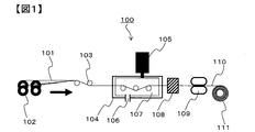
- FIG. 1 Schematic cross-sectional view of an example of the manufacturing method according to the present invention
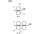
- a schematic view of an example of a cooling mechanism of a tape-like prepreg holding structure by roller-shaped parts A schematic view of an example of a cooling mechanism of a tape-like prepreg holding structure by roller-shaped parts
- a schematic view of an example of a cooling mechanism of a tape-like prepreg contact structure by plate-shaped parts A schematic view of an example of a cooling mechanism of a tape-like prepreg holding structure using a combination of a roller-shaped part and a plate-shaped part
- the present invention relates to a tape-like prepreg containing reinforcing fibers oriented in one direction and a thermoplastic resin composition, and a method for producing the same.
- the tape-like prepreg of the present invention is a tape-like prepreg comprising reinforcing fibers oriented in one direction and a thermoplastic resin composition,
- the arithmetic average roughness (Ra) measured based on JIS B 0601: 2013 in the direction orthogonal to the orientation direction of the reinforcing fibers is 0.1 to 10 ⁇ m, and
- the tape-like prepreg having a length of 100 mm in the fiber orientation direction is placed on a flat surface so that the end floats upward.
- the tape-like prepreg means a prepreg having a continuous length in the direction in which the reinforcing fibers are oriented. The width is usually 1000 mm in many cases, but this is not the case. In addition, the thing of a tape-like prepreg may only be called a prepreg.
- the tape-like prepreg of the present invention has an arithmetic average roughness (Ra) of 0.1 to 10 ⁇ m, which is measured based on JIS B 0601: 2013 in the direction orthogonal to the orientation direction of the reinforcing fibers, and )
- Ra arithmetic average roughness
- the tape-like prepreg of the present invention is a tape-like prepreg comprising a reinforcing fiber oriented in one direction, and a thermoplastic resin composition
- the maximum cross-sectional height (Wt) of the waviness curve measured based on JIS B 0601: 2013 in the direction orthogonal to the orientation direction of the reinforcing fiber is 80 ⁇ m or less
- a tape-like prepreg having a warp rate of 5% or less as determined by the above (i) to (iii) can be mentioned.
- the maximum cross-sectional height (Wt) of the waviness curve measured based on JIS B 0601: 2013 in the direction orthogonal to the orientation direction of the reinforcing fibers is 80 ⁇ m or less, and the above (i) to (iii) ) Is 5% or less, so that it has a good handling property when handled manually during molding or when applied to an automatic machine, and has a desired shape when laminating or reinforcing other members
- the tape-like prepreg can be easily provided, and the handling property at the time of bonding can be improved, and the tape-like prepreg excellent in the adhesion to other members can be provided.
- a tape-like prepreg of the present invention is a tape-like prepreg comprising a reinforcing fiber oriented in one direction and a thermoplastic resin composition
- the arithmetic average roughness (Ra) measured based on JIS B 0601: 2013 in the direction orthogonal to the orientation direction of the reinforcing fibers is 0.1 to 10 ⁇ m, and in the direction orthogonal to the orientation direction of the reinforcing fibers
- the maximum cross-sectional height (Wt) of the undulation curve measured based on JIS B 0601: 2013 is 80 ⁇ m or less, and More preferably, it is a tape-like prepreg having a warp rate of 5% or less as determined by the above (i) to (iii).
- the tape-like prepreg can be easily placed along the desired shape during lamination or when reinforcing other members, and the handling during molding can be improved, and the surface is smooth. It is possible to provide a tape-like prepreg in which the adhesion improvement with other members is compatible.
- the reinforcing fibers oriented in one direction are substantially uniformly distributed in the tape-like prepreg without being localized at a specific position in a direction perpendicular to the direction of orientation of the reinforcing fibers. It is preferable that the gap between reinforcing fibers oriented in one direction be filled with the thermoplastic resin composition. That is, in the tape-like prepreg of the present invention, it is preferable that the reinforcing resin oriented in one direction be impregnated with the thermoplastic resin composition.
- a melting method, a powder method, a film method, mixed fiber (commingle The law etc. are illustrated.
- the method of impregnation is not particularly limited, but a melting method which does not require processing of the thermoplastic resin composition in advance is preferably used. Further preferred production methods will be described later.
- the reinforcing fibers used in the tape-shaped prepreg of the present invention are not particularly limited, but carbon fibers, metal fibers, organic fibers and inorganic fibers are exemplified, and these may be used by mixing.
- carbon fibers examples include polyacrylonitrile (Poly Acrylo-Nitrile) carbon fibers (hereinafter sometimes abbreviated as PAN carbon fibers), pitch carbon fibers, cellulosic carbon fibers, vapor grown carbon fibers, and the like.
- PAN-based carbon fibers are carbon fibers made of polyacrylonitrile fiber as a raw material.
- Pitch-based carbon fibers are carbon fibers made from petroleum tar or petroleum pitch.
- Cellulose-based carbon fibers are carbon fibers that use viscose rayon or cellulose acetate as a raw material.
- Vapor grown carbon fibers are carbon fibers that use hydrocarbons or the like as a raw material.
- PAN-based carbon fiber is preferably used in that it is excellent in the balance between strength and elastic modulus.
- Examples of the organic fibers include fibers made of an organic material such as aramid fibers, polyphenylene sulfide fibers, polyester fibers, polyamide fibers and polyethylene fibers.
- Examples of aramid fibers include para-aramid fibers excellent in strength and elastic modulus and meta-aramid fibers excellent in flame retardancy and long-term heat resistance.
- Examples of para-aramid fibers include poly-p-phenylene terephthalamide fibers, copoly-p-phenylene-3,4'-oxydiphenylene terephthalamide fibers, etc.
- meta-aramid fibers poly-meta-phenylene isophthalamide fibers and the like Can be mentioned.
- As aramid fibers para-aramid fibers having a higher elastic modulus than meta-aramid fibers are preferably used.
- the inorganic fibers include fibers made of inorganic materials such as glass, basalt, silicon carbide and silicon nitride.
- glass fiber although E glass fiber (for electricity), C glass fiber (food resistance), S glass fiber, T glass fiber (high strength, high elastic modulus) etc. are illustrated, you may use any of these.
- Basalt fiber is a fiber of mineralized basalt and is a highly heat-resistant fiber. Basalt generally contains 9 to 25% by mass of FeO or FeO 2 which is a compound of iron and 1 to 6% by mass of TiO or TiO 2 which is a compound of titanium. It is also possible to fiberize.
- a reinforcing fiber one or a plurality of types of reinforcing fibers of carbon fiber, glass fiber, basalt fiber, and aramid fiber.
- a carbon fiber that efficiently exhibits mechanical properties such as weight reduction and strength.
- a composite effect can be expected by combining these fibers. For example, by combining carbon fibers and glass fibers, a high reinforcing effect by carbon fibers and a cost due to inexpensive glass fibers Can be compatible.
- the reinforcing fibers are usually formed by arranging one or more reinforcing fiber bundles in which a large number of single fibers are bundled.
- the total number of filaments of the reinforcing fibers (the number of single fibers) when one or more reinforcing fiber bundles are arranged is in the range of 1,000 to 2,500,000 in the tape-like prepreg of the present invention Is preferred.
- the total number of filaments of reinforcing fibers in the tape-like prepreg of the present invention is preferably 1,000 to 1,000,000, more preferably 1,000 to 600,000, 1 In particular, 1,000 to 300,000 are preferable.
- the upper limit and the lower limit may be combined.
- the upper limit of the total number of filaments of the reinforcing fiber is selected so as to maintain good productivity, dispersibility, and handleability, in consideration of the balance with the dispersibility and the handleability.
- the average diameter of single fibers of reinforcing fibers is preferably 5 to 10 ⁇ m, more preferably 6 to 8 ⁇ m.
- the upper limit and the lower limit may be combined.
- the tensile strength of the reinforcing fiber is preferably 3,000 to 6,000 MPa.
- the strength of the reinforcing fiber as referred to herein means one calculated on a single fiber basis as shown in the following equation.
- Reinforcement fiber strength [MPa] (single fiber strength [N]) / single fiber cross section [mm 2 ]
- the reinforcing fiber may be provided with a sizing agent on the surface in order to improve the adhesiveness, the composite comprehensive property, and the high-order processability.
- viscosity adjustment of components such as bisphenol type epoxy compound, linear low molecular weight epoxy compound, polyethylene glycol, polyurethane, polyester, emulsifier or surfactant, scratch resistance improvement, fuzz resistance improvement, focusing property improvement What is mixed for the purpose of improvement of high-order processability etc. is preferable.
- the means for applying the sizing agent to the reinforcing fiber is not particularly limited.
- a method of immersing the reinforcing fiber in the sizing solution through a roller a method of contacting the reinforcing fiber on the roller to which the sizing solution is attached, sizing There is a method of atomizing the liquid and spraying it onto the reinforcing fiber.
- either a batch system or a continuous system may be used, but a continuous system which can be reduced in variation with a high productivity is preferable.
- thermoplastic resin contained in the thermoplastic resin composition in the tape-shaped prepreg of the present invention is not particularly limited as long as it is a thermoplastic resin, for example, polypropylene, polyethylene, polystyrene, polyvinyl chloride, polyvinyl acetate, ABS resin, polyethylene terephthalate, polybutylene terephthalate, polyamide, polyamideimide, polyacetal, polycarbonate, modified polyphenylene oxide, polyvinyl alcohol, polyalkylene oxide, polysulfone, polyphenylene sulfide, polyarylate, polyetherimide, polyetheretherketone, polyethersulfone , Polyimide, polymethyl methacrylate, polysulfone and the like.
- a thermoplastic resin for example, polypropylene, polyethylene, polystyrene, polyvinyl chloride, polyvinyl acetate, ABS resin, polyethylene terephthalate, polybutylene terephthalate, polyamide, polyamideimide,
- thermoplastic resin composition in the tape-like prepreg of the present invention. Is preferred.
- the polyamide resin is a polyamide having an amino acid, a lactam or a diamine and a dicarboxylic acid as main components.
- the main components thereof include amino acids such as 6-aminocaproic acid, 11-aminoundecanoic acid, 12-aminododecanoic acid, and paraaminomethylbenzoic acid, lactams such as ⁇ -caprolactam, ⁇ -laurolactam, and tetramethylene diamine Hexamethylenediamine, 2-methylpentamethylenediamine, nonamethylenediamine, undecamethylenediamine, dodecamethylenediamine, 2,2,4 / 2,4,4-trimethylhexamethylenediamine, 5-methylnonamethylenediamine, Metaxylylenediamine, paraxylylenediamine, 1,3-bis (aminomethyl) cyclohexane, 1,4-bis (aminomethyl) cyclohexane, 1-amino-3-
- the reason for expressing the polyamide resin with the raw materials is in view of the difficulty in expressing the structure when a plurality of these are combined.
- the purpose is to specify the structure of the polymer. That is, the raw materials are not limited or those manufactured from different raw materials are not excluded (the same applies hereinafter).
- polyamide resin particularly useful as the thermoplastic resin contained in the thermoplastic resin composition in the tape-like prepreg of the present invention include polycaproamide (nylon 6) and polyhexamethylene adipamide (nylon 66). ), Polytetramethylene adipamide (nylon 46), polyhexamethylene sebacamide (nylon 610), polyhexamethylene dodecamide (nylon 612), poêtcane amide (nylon 11), poly dodecane amide (nylon 12), Polycaproamide / polyhexamethylene adipamide copolymer (nylon 6/66), polycaproamide / polyhexamethylene terephthalamide copolymer (nylon 6 / 6T), polyhexamethylene adipamide / polyhexamethylene terephthalamide copolymer (nylon 6 / 6T), polyhexamethylene adipamide / polyhexamethylene isophthalamide / polycaproamide copolymer (nylon 66 / 6
- the warpage rate of the tape-like prepreg is measured by the following (i) to (iii).
- (I) A tape-like prepreg having a length of 100 mm in the fiber orientation direction is placed on a flat surface so that its end floats upward. At this time, a tape with a long tape length can be cut into a sample of 100 mm, but care should be taken so that no warping occurs at the time of cutting. It is necessary to ensure that the tape-like prepreg does not float or sink unevenly on a flat surface, it is preferable to stand on a hard flat surface, and it is preferable to stand on a smooth flat surface .
- Warpage ratio (%) Warpage length [mm] / 100 [mm] ⁇ 100
- the warp rate of the tape-like prepreg in the present invention is 5% or less, and more preferably 3% or less.
- the warpage rate exceeds 5%, it is difficult to make the tape-like prepreg conform to a desired shape during lamination or when reinforcing other members, and the handleability at the time of molding is deteriorated. Although it is practically difficult to completely eliminate the warp, in the measurement method used in the present invention, both ends of the tape-like prepreg are completely in contact with the smooth surface due to the self-weight of the tape-like prepreg. In some cases, the lower limit of the warpage rate in the present invention is 0%.
- the tape-like prepreg of the present invention has a surface roughness (Ra) in the direction orthogonal to the reinforcing fiber measured based on JIS B 0601: 2013 of 10 ⁇ m or less, more preferably 8.0 ⁇ m or less, still more preferably 6 .3 ⁇ m or less.
- the surface roughness (Ra) exceeds 10 ⁇ m, the handleability at the time of lamination or at the time of reinforcing other members is deteriorated, and the productivity is inferior.
- the lower limit is considered to be 0.1 ⁇ m or more, and 0.4 ⁇ m or more can withstand practical use, which is preferable depending on the application. And, from that point of view, more preferably 0.8 ⁇ m or more. If the thickness is less than 0.1 ⁇ m, the adhesion when reinforcing other members may be poor.
- the upper limit and the lower limit may be combined.
- the heat absorption capacity Pc [W] of the cooling mechanism and the cooling mechanism are passed in 1 second.
- the ratio of the volume Qp [m 3 / s] of the prepreg to be made, Pc / Qp [W ⁇ s / m 3 ] may be adjusted.
- the thickness of the tape-like prepreg in the present invention is preferably 0.05 to 15 mm, more preferably 0.2 to 15 mm, and still more preferably 0.2 to 5 mm.
- the upper limit and the lower limit may be combined. If the thickness of the tape-like prepreg is 0.05 mm or more, the productivity is improved by reducing the number of laminated sheets and the reinforcing effect is excellent, and if the thickness of the tape-like prepreg is 15 mm or less, other members are reinforced during lamination. It is excellent in the handling at the time of.
- the thickness of the tape-like prepreg can be adjusted by the gap thickness of the nozzle disposed at the outlet side of the tank, ie, downstream.
- the thickness of the tape-like prepreg is a value obtained by arithmetically averaging the measured values of the thickness of 15 or more different points of the tape-like prepreg.
- the fiber volume content in 100% by volume of the tape-like prepreg of the present invention is preferably 30 to 70% by volume, more preferably 35 to 65% by volume, and still more preferably 40 to 60% by volume.
- the upper limit and the lower limit may be combined.
- the fiber volume content is 30% by volume or more, the mechanical properties and reinforcing effect of the tape-like prepreg are excellent. It is excellent in the impregnatability of the thermoplastic resin composition to a reinforced fiber at the time of manufacturing a tape-like prepreg as a fiber volume content rate is 70 volume% or less.
- the porosity in 100% by volume of the tape-like prepreg of the present invention is preferably 5% by volume or less, more preferably 4% by volume or less, and still more preferably 3% by volume or less.
- the porosity of the tape-shaped prepreg is preferably as small as possible, so the lower limit is 0% by volume. The method of measuring the porosity is as described later in the Examples.
- thermoplastic resin composition As a means for controlling the porosity to 5% by volume or less, there are means such as lowering the melt viscosity of the thermoplastic resin composition to be impregnated and increasing the pressure applied during the impregnation.
- the maximum cross-sectional height (Wt) of an undulation curve measured based on JIS B 0601: 2013 is preferably 80 ⁇ m or less, more preferably 60 ⁇ m or less.
- the tape-like prepreg can be easily placed in a desired shape during lamination or when reinforcing other members, and the handleability at the time of molding is improved.
- the lower the maximum cross-sectional height of the undulation curve is the lower the better, but it may be practically difficult to make it zero, so the lower limit is usually 1 ⁇ m.
- thermoplastic resin composition in a molten state is impregnated into a plurality of continuous reinforcing fibers introduced from the inlet of the tank, in a tank having an inlet and an outlet.
- a method for producing a tape-like prepreg comprising the thermoplastic resin composition and a plurality of continuous reinforcing fibers by passing through a cooling mechanism after passing through the outlet of the tank.
- the Pc and Qp are as follows (A Method for producing a tape-like prepreg satisfying the formula 2.8 ⁇ 10 8 ⁇ Pc / Qp ⁇ 23.2 ⁇ 10 8 (A)
- the tape-like prepreg can be surely cooled and solidified, and the shrinkage of the thermoplastic resin composition can be controlled, and a tape-like prepreg excellent in surface smoothness and dimensional accuracy can be produced at a high level. It can be manufactured with sex.
- the present invention which relates to a method for producing a tape-like prepreg containing a plurality of continuous reinforcing fibers and a thermoplastic resin, has a step of passing a plurality of continuous reinforcing fibers in a tank containing a thermoplastic resin.
- a manufacturing method of the tape-like prepreg which has the process of making the tank containing a thermoplastic resin pass the continuous reinforcement fiber of the number of winds, a melting method, a powder method, a mixed fiber (commingle) method etc. are illustrated, for example.
- a melting method which does not need to process the thermoplastic resin in advance is preferably used.
- FIG. 1 shows a method for producing a tape-like prepreg according to an embodiment of the present invention
- 100 shows the entire apparatus for producing a tape-like prepreg.
- a plurality of bobbins 102 in which the continuous reinforcing fibers 101 are wound are prepared, and the plurality of continuous reinforcing fibers 101 are continuously sent out from the plurality of bobbins 102 through the yarn path guide 103.
- thermoplastic resin composition 107 in a molten state can be impregnated into the plurality of continuous reinforcing fibers 101 introduced from the inlet of the tank when passing through the tank 104.
- the plurality of continuous reinforcing fibers 101 impregnated with the thermoplastic resin composition 107 are continuously pulled off by the pulling force of the pulling roll 109 and passed through the outlet of the tank 104 and then passed through the cooling mechanism 108.
- the thermoplastic resin composition 107 is cooled and solidified to produce a tape-like prepreg 110 composed of the thermoplastic resin composition 107 and the continuous reinforcing fibers 101. It is preferable that the manufactured tape-shaped prepreg 110 be wound up by a winding roll 111 and made into a roll shape.
- the width dimension and thickness dimension of the tape-shaped prepreg 110 are defined by the dimensions of the outlet of the tank 104, and the dimensions of the tape-shaped prepreg 110 can be changed by changing the outlet dimension of the tank 104.
- the thermoplastic resin composition 107 filled in the tank 104 may pass through the tank 104 together with the plurality of continuous reinforcing fibers 101, and the thermoplastic resin composition 107 in the tank 104 may be continuous. When it does not pass along with the reinforcing fiber 101, the surplus thermoplastic resin composition 107 in the tank 104 can be discharged from the discharge port 106.
- the continuous reinforcing fibers in the obtained tape-like prepreg can be oriented in one direction. That is, in the tape-like prepreg containing a plurality of continuous reinforcing fibers obtained by the method of producing a tape-like prepreg of the present invention and a thermoplastic resin, the orientation direction of the plurality of continuous reinforcing fibers is not particularly limited. It is preferable to be orientated in one direction, since it is excellent in workability at the time of carrying out.
- the method for producing a tape-shaped prepreg according to the present invention it is preferable to use one or a plurality of roller-shaped parts as cooling components constituting the cooling mechanism 108. It is preferable to use a roller-shaped component as a cooling part constituting the cooling mechanism 108, since friction does not occur between the roller and the tape-like prepreg, so that the possibility of damaging the tape-like prepreg is low.
- FIG. 2 An example in the case of using a roller-shaped component as a component for cooling which comprises the said cooling mechanism 108 is demonstrated using FIG. 2, and FIG.
- FIG. 2 shows one embodiment of the cooling mechanism 108 in FIG. 1, and is a schematic view showing an example of the cooling mechanism in which the tape-shaped prepreg 201 is held in the roller-shaped component.
- a cooling mechanism may be described as a cooling mechanism of a tape-like prepreg holding structure by roller-shaped parts.
- 200 shows a cooling mechanism of the tape-like prepreg holding structure by the roller-shaped parts when one roller-shaped part 202 is used.
- the tape-like prepreg 201 can be cooled and solidified by bringing the tape-like prepreg 201 having passed through the outlet of the tank 104 into contact with one side of the roller-shaped component 202 and passing it.
- Reference numeral 203 denotes a cooling mechanism of the tape-like prepreg holding structure using roller-shaped parts when two roller-shaped parts 202 are used.
- the tape-like prepreg 201 can be cooled and solidified by bringing the tape-like prepreg 201 that has passed through the outlet of the tank 104 into contact with the roller-shaped component 202 and passing it on one side.
- Reference numeral 204 denotes a cooling mechanism of a tape-like prepreg holding structure using roller-shaped parts when four roller-shaped parts 202 are used, and the method of cooling the tape-like prepreg 201 is the same as that of 203.
- the temperature of the roller-shaped parts constituting the cooling mechanism is adjusted by, for example, flowing water inside.
- FIG. 3 shows one embodiment of the cooling mechanism 108 in FIG. 1, and another roller-shaped component constituting the cooling mechanism is installed on the opposite side of one roller-shaped component to form a pair.
- FIG. 3 shows an example of the cooling mechanism of the structure arrange
- a cooling mechanism may be described as a cooling mechanism of a tape-like prepreg holding structure by roller-shaped parts.
- Reference numeral 300 denotes a cooling mechanism of the tape-like prepreg holding structure by the roller-shaped parts when two roller-shaped parts 302 are used.
- the tape-like prepreg 301 can be cooled and solidified by holding the tape-like prepreg 301 having passed through the outlet of the tank 104 on both sides with the roller-shaped component 302 and bringing it into contact and passing.
- Reference numeral 303 denotes a cooling mechanism of the tape-like prepreg holding structure by the roller-shaped parts when four roller-shaped parts 302 are used, and the method of cooling the tape-shaped prepreg 301 is the same as 300.
- the method for producing a tape-like prepreg of the present invention it is also preferable to use one or a plurality of plate-shaped ones as cooling parts constituting the cooling mechanism 108.
- a plate-shaped component is used as the cooling component constituting the cooling mechanism 108, the contact time between the plate-shaped component for cooling and the tape-like prepreg can be extended, which is preferable in that the cooling becomes efficient. .
- FIG. 4 shows one embodiment of the cooling mechanism 108 in FIG. 1, and is a schematic view showing an example of the cooling mechanism in which the tape-shaped prepreg 401 is brought into contact with the plate-shaped component.
- a cooling mechanism may be described as a cooling mechanism of the tape-like prepreg contact structure by plate-shaped parts.
- a reference numeral 400 denotes a cooling mechanism of the tape-like prepreg contact structure by the plate-shaped component when one plate-shaped component 402 is used.
- the tape-like prepreg 401 can be cooled and solidified by bringing the tape-like prepreg 401 having passed through the outlet of the tank 104 into contact with the plate-shaped component 402 and passing it.
- 403 shows the cooling mechanism of the tape-like prepreg contact structure by the plate-shaped parts when two plate-shaped parts 402 are used.
- the tape-like prepreg 401 can be cooled and solidified by bringing the tape-like prepreg 401 having passed through the outlet of the tank 104 into contact with both sides of the plate-shaped component 402 and passing it.
- 404 shows a cooling mechanism of the tape-like prepreg contact structure by the plate-like parts when four plate-like parts 402 are used, and the system for cooling the tape-like prepreg 401 is the same as 403.
- the method for producing a tape-like prepreg of the present invention it is also preferable to use one or a plurality of roller-shaped ones and a plurality of plate-shaped ones as cooling parts constituting the cooling mechanism 108.
- a roller-shaped part and a plate-shaped part are used in combination as the cooling part constituting the cooling mechanism 108, the contact time with the tape-shaped prepreg by the reduction of the friction force by the roller and the part for the plate-shaped cooling It is preferable in that the effect which becomes long can be obtained simultaneously.
- FIG. 5 shows one embodiment of the cooling mechanism 108 in FIG. 1, and another plate-shaped component which constitutes the cooling mechanism is installed on the opposite side of one roller-shaped component to constitute the cooling mechanism.
- FIG. 5 shows an example of the cooling mechanism of the structure which clamped the tape-like prepreg by the components of the roller shape and plate-shaped components which are.
- a cooling mechanism may be referred to as a cooling mechanism of a tape-like prepreg holding structure using a combination of a roller-shaped component and a plate-shaped component.
- Reference numeral 500 denotes a cooling mechanism in the case where one roller-shaped component 502 and one plate-shaped component 503 are used.
- the tape-like prepreg 501 can be cooled and solidified by holding the tape-like prepreg 501 having passed through the outlet of the tank 104 between the roller-shaped part 502 and the plate-shaped part 503 from both sides and bringing it into contact and passing.
- Reference numeral 504 denotes a cooling mechanism in the case where two roller-shaped parts 502 and two plate-shaped parts 503 are used, and the system for cooling the tape-like prepreg 501 is the same as 500.
- Pc / Qp is large means that the heat absorption capacity of the cooling mechanism is large relative to the volume of the tape-like prepreg passing through the cooling mechanism in 1 second, and the tape-like prepreg can be surely cooled and solidified.
- Qp exceeds 23.2 ⁇ 10 8 , a cooling mechanism having an endothermic capacity more than necessary is required, and the equipment is enlarged, resulting in an increase in production cost.
- Pc / Qp is small means that the heat absorption capacity of the cooling mechanism is smaller than that of the tape-like prepreg passing through the cooling mechanism in 1 second, and the tape-like prepreg can not be sufficiently solidified by cooling.
- the heat absorption capacity Pc [W] of the entire cooling mechanism is preferably 1.2 to 3.9 ⁇ 10 5 regardless of the number of parts for cooling constituting the cooling mechanism. More preferably, it is 3.9 to 2.7 ⁇ 10 5 , more preferably 6.9 to 1.6 ⁇ 10 5 .
- the upper limit and the lower limit may be combined.
- the cooling mechanism is installed for the purpose of impregnating the thermoplastic resin into the continuous reinforcing fiber in the tank and cooling the tape-like prepreg which is drawn out from the outlet of the tank and heated.
- the cooling mechanism If the temperature of the prepreg naturally decreases during passage, that is, if there is no system for adjusting the temperature of the mechanism, it is not referred to as the cooling mechanism mentioned here.
- Pc 1.2 or more, a cooling mechanism having high endothermic ability is obtained, and a tape-like prepreg excellent in dimensional accuracy and surface smoothness can be obtained.
- Pc 3.9 ⁇ 10 5 or less, the cooling mechanism can be miniaturized and the structure can be simplified.
- the heat absorption capacity of the cooling mechanism may be designed according to the volume of the tape-like prepreg passing through the cooling mechanism in one second according to the purpose of the present invention according to the type and temperature conditions of the thermoplastic resin used. preferable.
- the volume Qp [m 3 / s] of the tape-like prepreg passing through the cooling mechanism in 1 second is preferably 4.2 ⁇ 10 ⁇ 9 to 1.7 ⁇ 10 ⁇ 4. More preferably, they are 8.3 ⁇ 10 ⁇ 9 to 1.3 ⁇ 10 ⁇ 4 , more preferably 1.3 ⁇ 10 ⁇ 8 to 8.3 ⁇ 10 ⁇ 5 . It may be a range combining any of the above upper limit and the lower limit. If Qp is 1.7 ⁇ 10 -4 or less, the heat absorption capacity of the cooling mechanism is small, and it becomes easy to obtain a tape-shaped prepreg with high dimensional accuracy. In addition, high productivity can be obtained when Qp is 4.2 ⁇ 10 ⁇ 9 or more.
- the volume Qp [m 3 / s] of the tape-like prepreg passing through the cooling mechanism in 1 second is the velocity [m / s] of the tape-like prepreg passing the cooling mechanism and the outlet size (area [m 2 ] of the tank Can be obtained from the product of
- the parts for cooling which constitute the cooling mechanism used in the method for producing the tape-like prepreg of the present invention are not limited in cross-sectional shape, and may be roller-shaped or plate-shaped. Furthermore, there is no limitation on the size, the number, and the arrangement of the cooling parts constituting each cooling mechanism, and even if the cooling mechanism is constituted only by the roller-shaped parts, the cooling mechanism is constituted only by the plate-shaped parts However, the cooling mechanism may be configured by combining the roller-shaped part and the plate-shaped part. When a roller-shaped component is used, the roller-shaped component may be supported by a bearing or the like, and may be naturally rotated, or may be driven and rotated by using a motor or the like.
- the area through which the tape-like prepreg on the surface of the plate passes is a flat surface, and the corner of the plate end that is the introduction point to the cooling mechanism of the tape-like prepreg has a curved surface Or a tapered surface.
- the contact area of the tape-like prepreg to the cooling mechanism can be increased as compared with the case where a roller-shaped component is used, so a high cooling solidification effect can be obtained with a small-scale facility .
- Arithmetic mean roughness (Ra) measured by JIS B 0601: 2013 of parts for cooling constituting the cooling mechanism used in the method for producing a tape-like prepreg of the present invention is different from roller-shaped parts or plate-shaped parts.
- the thickness is preferably 0.1 to 25.0 ⁇ m, more preferably 0.4 to 12.5 ⁇ m, and still more preferably 0.8 to 6.3 ⁇ m.
- the upper limit and the lower limit may be combined. Both the parts for cooling that constitute the cooling mechanism and the tape-like prepreg are suitable if the heat absorption capability of the cooling mechanism and the friction force acting between the tape-like prepreg when passing through the cooling mechanism and the cooling mechanism are both appropriate.
- the Ra of the tape-like prepreg is 10 to 20 times the Ra of the cooling part constituting the cooling mechanism, or the cooling mechanism is adjusted according to the desired Ra of the tape-like prepreg. It is preferable to select Ra of the component for cooling which comprises.
- the parts for cooling which comprise the cooling mechanism used for the manufacturing method of the tape-like prepreg of this invention have a structure which can be temperature-controlled. Even if the cooling mechanism is configured using either a roller-shaped component or a plate-shaped component, when configuring a cooling mechanism using a plurality of cooling components, each cooling component is independent of each other Preferably, the temperature can be adjusted.
- the method and means for adjusting the temperature of parts for cooling a method of flowing a fluid inside the parts for cooling, a method of applying a fluid to the parts for cooling from the outside of the parts for cooling, and cooling
- the system which fixes the apparatus used as a heat source to the inside of the parts for parts may be used.
- the method of flowing the fluid inside the parts for cooling is preferably used because the structure of the parts for cooling is simple and the temperature control is efficiently performed.
- the fluid to be supplied to the inside of the part for cooling constituting the cooling mechanism is not particularly limited, but water, steam, air, oil, antifreeze liquid (ethylene glycol etc.) and the like are exemplified.
- the cross-sectional shape of the flow path formed inside the cooling part constituting the cooling mechanism is not particularly limited when using either a roller shape or a plate shape, and it may be circular or square. It is preferable to take a circular cross-section as the cross-sectional shape of the flow path formed inside the component for cooling, since the structure of the component for cooling can be simplified.
- the cooling mechanism used in the method for producing a tape-like prepreg of the present invention is determined based on the size, the number, the set temperature, the flow rate of the fluid to be used, etc. of the cooling parts constituting the cooling mechanism. It is preferable to design so as to obtain a desired endothermic capacity in accordance with constraints such as specifications and space. In particular, with regard to the size of parts for cooling, since the contact length between the tape-like prepreg and the part for cooling is approximately proportional to the cooling capacity, it is necessary to calculate and design a size commensurate with the cooling capacity. desirable.
- the shape of the cooling component constituting the cooling mechanism used in the method for producing the tape-like prepreg of the present invention is not particularly limited, but it becomes a pair of sandwiching the tape-like prepreg on the opposite side of one cooling component.
- the cooling components sandwiching the tape-like prepreg are used. It is preferable that it is a structure which can set distance arbitrarily.
- a method for arbitrarily setting the distance between parts for cooling is not particularly limited, and a method of adjusting the position of the top dead center or the bottom dead center of the air cylinder or hydraulic cylinder to a desired distance, or between parts for cooling The method of sandwiching a shim plate etc. are mentioned. If the distance between parts for cooling can be set arbitrarily, there are advantages such as excellent workability in preparation for production, and the ability to adjust the degree of contact between the parts for cooling and the tape-like prepreg that constitute the cooling mechanism. If the distance between the parts for cooling is too narrow, the tape-like prepreg can not pass through the cooling mechanism. If the distance between the parts for cooling is too large, the tape-like prepreg may not come in contact with the cooling mechanism, and the tape-like prepreg may not be able to be cooled and solidified.
- the shape of the cooling component constituting the cooling mechanism used in the method for producing the tape-like prepreg of the present invention is not particularly limited, but it becomes a pair of sandwiching the tape-like prepreg on the opposite side of one cooling component.
- the cooling when defining the distance between the cooling components It is preferable to be able to optionally set the force to fix the parts in position in the specified position.
- a method of fixing by fixing means can be adopted.
- the parts for cooling which constitute the cooling mechanism It is preferable that it is a structure which can set the force to fix arbitrarily. If the force for fixing the parts for cooling can be adjusted arbitrarily, an appropriate load can be given to the tape-like prepreg passing through the cooling mechanism with respect to the production conditions of the tape-like prepreg. If the force for fixing the parts for cooling is too small, the reaction force generated when the tape-like prepreg passes through the cooling mechanism causes problems such as the inability to obtain the desired dimensions of the tape-like prepreg.
- the tape-like prepreg passing through the outlet of the tank and passing through the cooling mechanism has a form continuous in a direction perpendicular to the passing direction (ie only one tape-like pull prepreg) Or a divided form (i.e., an aspect in which a plurality of tape-like prepregs are made to run in parallel and manufactured simultaneously).
- the cooling parts constituting the cooling mechanism are not in the form of a roller or plate, and the tape-like prepreg
- the surface of the cooling component to be in contact may have a uniform flat surface, or may have an uneven shape corresponding to the dimensions of the tape-like prepreg.
- the tape-shaped prepreg continuous in the direction orthogonal to the passing direction of the tape-shaped prepreg is excellent in productivity.
- the tape-shaped prepregs divided in the direction orthogonal to the passage direction of the tape-shaped prepreg have high dimensional freedom, and therefore have high ability to follow various component sizes for cooling.
- bobbins 102 on which reinforcing fibers 101 are wound are prepared, and the reinforcing fibers 101 are continuously sent out from the bobbins 102 through the yarn path guides 103.
- the thermoplastic resin composition 107 quantitatively supplied from the feeder 105 filled with the thermoplastic resin composition was impregnated into the reinforcing fiber 101 fed continuously.
- the reinforcing fiber 101 impregnated with the thermoplastic resin composition 107 in the tank 104 was continuously drawn from a nozzle having a width of 50 mm and a thickness of 0.30 mm, which is disposed on the downstream side of the tank 104.
- the reinforcing fiber 101 was used in such an amount that the total cross-sectional area was 50% of the cross-sectional area of the nozzle gap of the tank 104.
- the reinforcing fiber 101 pulled out by the take-up roll 109 passes through the cooling mechanism 108, is cooled and solidified, and is wound up by the take-up roll 111 to obtain a tape-like prepreg 110 having a fiber volume content of 50% by volume.
- (c-1) was used as the shape and the number of parts for cooling which constitute the cooling mechanism.
- the surface roughness (Ra) was all 0.2 ⁇ m.
- Example 2 It implemented similarly to Example 1 except having changed the space
- Example 3 It implemented similarly to Example 1 except having changed the space
- Example 4 It implemented similarly to Example 1 except having changed the space
- Example 5 It is carried out in the same manner as in Example 1 except that a part for cooling having a surface roughness (Ra) of 12.0 ⁇ m is used for the part for cooling having a roller shape used in the cooling mechanism, and the surface roughness is different.
- the tape-shaped prepreg 110 was obtained. The results are shown in Table 1-1.
- Example 6 It implemented similarly to Example 5 except having changed the space
- Example 7 It implemented similarly to Example 5 except having changed the space
- Example 8 A tape-shaped prepreg having a different fiber volume content, which is carried out in the same manner as in Example 1, except that the amount of reinforcing fiber 101 used is changed so that the total cross-sectional area becomes 40% of the cross-sectional area of the nozzle gap of layer 104. I got 110. The results are shown in Table 1-2.
- Example 9 A tape-shaped prepreg having a different fiber volume content, which is carried out in the same manner as in Example 1, except that the amount of reinforcing fiber 101 used is changed so that the total cross-sectional area becomes 60% of the cross-sectional area of the nozzle gap of layer 104. I got 110. The results are shown in Table 1-2.
- Example 10 A tape-shaped prepreg 110 having different porosity was obtained in the same manner as in Example 1 except that the production rate was changed to twice that in Example 1. The results are shown in Table 1-2.
- Example 11 A tape-shaped prepreg 110 was obtained in the same manner as in Example 1 except that Pc / Qp was changed to 18.1 ⁇ 10 8 . The results are shown in Table 1-2.
- Example 12 The same procedure as in Example 11 was carried out except that the gap thickness of the nozzle of the tank 104 was changed to 0.15 mm, to obtain a tape-shaped prepreg 110 having a different thickness. The results are shown in Table 1-2.
- Example 13 The same procedure as in Example 1 was carried out except that the width of the air gap in the nozzle of the layer 104 was changed to 10 mm, and the thickness was changed to 0.05 mm, to obtain a tape-shaped prepreg 110 having different width and thickness. The results are shown in Table 1-3.
- Example 14 A tape-shaped prepreg 110 was obtained in the same manner as in Example 13 except that Pc / Qp was changed to 18.1 ⁇ 10 8 . The results are shown in Table 1-3.
- Example 15 The same procedure as in Example 2 was carried out except that the gap width of the nozzle of the layer 104 was changed to 300 mm, to obtain a tape-like prepreg 110 having different widths and thicknesses. The results are shown in Table 1-3.
- Example 16 A tape-shaped prepreg 110 was obtained in the same manner as in Example 15 except that Pc / Qp was changed to 18.1 ⁇ 10 8 . The results are shown in Table 1-3.
- Example 17 The same procedure as in Example 15 was carried out except that the gap thickness of the nozzle of the layer 104 was changed to 0.30 mm, to obtain a tape-like prepreg 110 having different widths and thicknesses. The results are shown in Table 1-3.
- Example 18 A tape-like prepreg 110 was obtained in the same manner as in Example 17 except that Pc / Qp was changed to 18.1 ⁇ 10 8 . The results are shown in Table 1-3.
- Example 19 A tape-shaped prepreg 110 was obtained in the same manner as in Example 13 except that (c-2) was used as the shape and the number of parts for cooling constituting the cooling mechanism. The results are shown in Table 2-1.
- Example 20 A tape-like prepreg 110 was obtained in the same manner as in Example 19 except that Pc / Qp was changed to 18.1 ⁇ 10 8 . The results are shown in Table 2-1.
- Example 21 A tape-like prepreg 110 was obtained in the same manner as in Example 2 except that (c-2) was used as the shape and the number of parts for cooling constituting the cooling mechanism. The results are shown in Table 2-1.
- Example 22 A tape-shaped prepreg 110 was obtained in the same manner as in Example 21 except that Pc / Qp was changed to 18.1 ⁇ 10 8 . The results are shown in Table 2-1.
- Example 23 The same procedure as in Example 21 was carried out except that the air gap thickness of the nozzle of the layer 104 was changed to 0.30 mm, to obtain a tape-like prepreg 110 having different width and thickness. The results are shown in Table 2-1.
- Example 24 A tape-like prepreg 110 was obtained in the same manner as in Example 23 except that Pc / Qp was changed to 18.1 ⁇ 10 8 . The results are shown in Table 2-1.
- Example 25 The same procedure as in Example 21 was carried out except that the gap width of the nozzle of the layer 104 was changed to 300 mm, to obtain a tape-like prepreg 110 having different width and thickness. The results are shown in Table 2-2.
- Example 26 A tape-shaped prepreg 110 was obtained in the same manner as in Example 25 except that Pc / Qp was changed to 18.1 ⁇ 10 8 . The results are shown in Table 2-2.
- Example 27 The same procedure as in Example 25 was carried out except that the air gap thickness of the nozzle of the layer 104 was changed to 0.30 mm, to obtain a tape-like prepreg 110 having different width and thickness. The results are shown in Table 2-2.
- Example 28 A tape-shaped prepreg 110 was obtained in the same manner as in Example 27 except that Pc / Qp was changed to 18.1 ⁇ 10 8 . The results are shown in Table 2-2.
- Comparative example 2 The same procedure as in Comparative Example 1 was carried out except that the gap thickness of the nozzle of the tank 104 was changed to 0.20 mm, to obtain a tape-shaped prepreg 110 having a different thickness. The results are shown in Table 3-1.
- Comparative example 3 It implemented similarly to the comparative example 1 except having changed the space
- Comparative example 4 The same procedure as in Comparative Example 1 was carried out except that the gap thickness of the nozzle of the tank 104 was changed to 0.15 mm, to obtain a tape-shaped prepreg 110 having a different thickness. The results are shown in Table 3-1.
- Comparative example 6 The same procedure as in Comparative Example 4 was carried out except that the gap width of the nozzle of the tank 104 was changed to 300 mm, to obtain a tape-shaped prepreg 110 having a different thickness. The results are shown in Table 3-1.
- Comparative example 7 The same procedure as in Comparative Example 6 was carried out except that the gap thickness of the nozzle of the tank 104 was changed to 0.30 mm, to obtain a tape-shaped prepreg 110 having a different thickness. The results are shown in Table 3-1.
- Comparative example 9 The same procedure as in Comparative Example 8 was carried out except that the gap thickness of the nozzle of the tank 104 was changed to 0.30 mm, to obtain a tape-shaped prepreg 110 having a different thickness. The results are shown in Table 3-2.
- Comparative example 11 The same procedure as in Comparative Example 8 was carried out except that the gap width of the nozzle of the tank 104 was changed to 300 mm, to obtain a tape-shaped prepreg 110 having a different thickness. The results are shown in Table 3-2.
- Comparative example 12 It implemented similarly to Comparative Example 11 except having changed the space
Landscapes
- Chemical & Material Sciences (AREA)
- Engineering & Computer Science (AREA)
- Mechanical Engineering (AREA)
- Composite Materials (AREA)
- Materials Engineering (AREA)
- Polymers & Plastics (AREA)
- Health & Medical Sciences (AREA)
- Chemical Kinetics & Catalysis (AREA)
- Medicinal Chemistry (AREA)
- Manufacturing & Machinery (AREA)
- Organic Chemistry (AREA)
- Inorganic Chemistry (AREA)
- Textile Engineering (AREA)
- Reinforced Plastic Materials (AREA)
Abstract
Description
前記強化繊維の配向方向と直交する方向における、JIS B 0601:2013に基づいて測定される算術平均粗さ(Ra)が0.1~10μm、かつ、
下記(i)~(iii)によって求められる反り率が5%以下である、テープ状プリプレグである。
(i)繊維配向方向の長さが100mmの前記テープ状プリプレグを平面上に端部が上方に浮く向きで静置する。
(ii)上記上方に浮いたテープの右端の最も高い位置から平面までの垂直距離をa、左端の最も高い位置から平面までの垂直距離をbとし、aとbの算術平均値を反り長と規定する。
(iii)下式で反り率を算出する。
反り率(%)=反り長[mm]/100[mm]×100
また、本発明のテープ状プリプレグの別の態様は、一方向に配向した強化繊維、及び、熱可塑性樹脂組成物を含むテープ状プリプレグであって、
前記強化繊維の配向方向と直交する方向における、JIS B 0601:2013に基づいて測定されるうねり曲線の最大断面高さ(Wt)が80μm以下、かつ、
下記(i)~(iii)によって求められる反り率が5%以下である、テープ状プリプレグである。
(i)繊維配向方向の長さが100mmの前記テープ状プリプレグを平面上に端部が上方に浮く向きで静置する。
(ii)前記上方に浮いたテープの右端の最も高い位置から平面までの垂直距離をa、左端の最も高い位置から平面までの垂直距離をbとし、aとbの算術平均値を反り長と規定する。
(iii)下式で反り率を算出する。
反り率(%)=反り長(mm)/100(mm)×100 また、本発明のテープ状プリプレグの製造方法は、溶融状態の熱可塑性樹脂組成物を、入口部及び出口部を有する槽内で、前記槽の入口部から導入された複数の連続強化繊維に含浸させ、
前記槽の出口部を通過させた後に、冷却機構を通過させて、前記熱可塑性樹脂組成物と複数の連続強化繊維からなるテープ状プリプレグを製造する方法において、
前記冷却機構の吸熱能力をPc[W]として、前記冷却機構を1秒間に通過する前記テープ状プリプレグの体積をQp[m3/s]とした際に、前記PcとQpとが下記(A)式を満たす、テープ状プリプレグの製造方法である。
2.8×10⁸ ≦ Pc/Qp ≦ 23.2×10⁸・・・(A)
前記強化繊維の配向方向と直交する方向における、JIS B 0601:2013に基づいて測定される算術平均粗さ(Ra)が0.1~10μm、かつ、
下記(i)~(iii)によって求められる反り率が5%以下である、テープ状プリプレグである。
(i)繊維配向方向の長さが100mmの前記テープ状プリプレグを平面上に端部が上方に浮く向きで静置する。
(ii)上記上方に浮いたテープの右端の最も高い位置から平面までの垂直距離をa、左端の最も高い位置から平面までの垂直距離をbとし、aとbの算術平均値を反り長と規定する。
(iii)下式で反り率を算出する。
反り率(%)=反り長[mm]/100[mm]×100
本発明において、テープ状プリプレグとは、強化繊維の配向した方向に連続した長さを持ったプリプレグのことをいう。幅については通常1000mmであることが多いが、この限りではない。なお、テープ状プリプレグのことを単にプリプレグと言うこともある。
前記強化繊維の配向方向と直交する方向における、JIS B 0601:2013に基づいて測定されるうねり曲線の最大断面高さ(Wt)が80μm以下、かつ、
上記(i)~(iii)によって求められる反り率が5%以下である、テープ状プリプレグが挙げられる。かかる場合において、前記強化繊維の配向方向と直交する方向における、JIS B 0601:2013に基づいて測定されるうねり曲線の最大断面高さ(Wt)が80μm以下、かつ、上記(i)~(iii)によって求められる反り率が5%以下であることにより、成形時に手作業で取り扱う、または自動機械に適用する際の取り扱い性が良好で、かつ積層時や他部材を補強する際に所望の形状にテープ状プリプレグを沿わせやすくなり、接着時の取り扱い性が向上すると共に、他部材との接着性に優れた、テープ状プリプレグを提供できる。
前記強化繊維の配向方向と直交する方向における、JIS B 0601:2013に基づいて測定される算術平均粗さ(Ra)が0.1~10μmであり、前記強化繊維の配向方向と直交する方向における、JIS B 0601:2013に基づいて測定されるうねり曲線の最大断面高さ(Wt)が80μm以下、であり、かつ、
上記(i)~(iii)によって求められる反り率が5%以下である、テープ状プリプレグであればより好ましい。かかる要件を満たすことによりことにより、積層時や他部材を補強する際に所望の形状にテープ状プリプレグを沿わせやすくなり、成型形時の取り扱い性が向上すると共に、表面が平滑であることから他部材との接着性向上を両立したテープ状プリプレグを提供できる。
強化繊維の強度[MPa]=(単繊維強力[N])/単繊維断面積[mm2]
また、強化繊維は、接着性やコンポジット総合特性、高次加工性を向上させるためにサイジング剤が表面に付与されていてもよい。サイジング剤には、ビスフェノール型エポキシ化合物、直鎖状低分子量エポキシ化合物、ポリエチレングリコール、ポリウレタン、ポリエステル、乳化剤あるいは界面活性剤などの成分を粘度調整、耐擦過性向上、耐毛羽性向上、集束性向上、高次加工性向上等の目的で混合したものが好ましい。
(i)繊維配向方向の長さが100mmのテープ状プリプレグを平面上に端部が上方に浮く向きで静置する。この時、テープ長さが長いものをカットして100mmのサンプルとすることができるが、カット時に反りが発生しないよう注意する。テープ状プリプレグが平面上で不均一に浮いたり、または沈み込むことがないようにする必要があり、固い平面上に静置することが好ましく、また、平滑な平面上に静置することが好ましい。
(ii)上方に浮いたテープの右端の最も高い位置から平面までの垂直距離をa、左端の最も高い位置から平面までの垂直距離をbとし、aとbの算術平均(相加平均)値を反り長と規定する。
(iii)下式で反り率を算出する。
反り率(%)=反り長[mm]/100[mm]×100
本発明におけるテープ状プリプレグの反り率は5%以下であり、3%以下であるとさらに好ましい。反り率が5%を超えると積層時や他部材を補強する際に所望の形状にテープ状プリプレグを沿わせることが難しく、成形時の取り扱い性が悪化する。また、反りを完全に解消することは現実的に困難であるものの、本発明で用いる測定方法においては、テープ状プリプレグの自重によって、テープ状プリプレグの両端部が平滑な表面上に完全に接触することもあるため、本発明における反り率の下限値は0%である。
前記槽の出口部を通過させた後に、冷却機構を通過させて、前記熱可塑性樹脂組成物と複数の連続強化繊維とからなるテープ状プリプレグを製造する方法において、
前記冷却機構の吸熱能力をPc[W]として、前記冷却機構を1秒間に通過する前記テープ状プリプレグの体積をQp[m3/s]とした際に、前記PcとQpとが下記(A)式を満たす、テープ状プリプレグの製造方法である。
2.8×10⁸≦Pc/Qp≦23.2×108・・・(A)
かかる構成を採ることにより、テープ状プリプレグを確実に冷却固化し、熱可塑性樹脂組成物の収縮をコントロールすることが出来るようになり、表面の平滑性と寸法精度に優れたテープ状プリプレグを高い生産性を持って製造することができる。
2.8×10⁸≦Pc/Qp≦23.2×108・・・(A)
すなわち、Pc/Qp[W・s/m3]は、2.8×108~23.2×108であり、
より好ましくは4.7×10⁸~20.4×10⁸、さらに好ましくは5.6×10⁸~19.3×10⁸である。上記の上限と下限のいずれを組み合わせた範囲であってもよい。
比重測定機(ALFA MIRAGE製、ELECTRONIC DENSIMETER SD-200L)を用いて測定した。
約0.5gのテープ状プリプレグを秤量(W1[g])した後、毎分50mLの窒素気流中、500℃の温度に設定した電気炉に120分間放置し、テープ状プリプレグ中の熱可塑性樹脂組成物を完全に熱分解させる。そして、毎分20Lの乾燥窒素気流中の容器に移し、15分間冷却した後の強化繊維を秤量(W2[g])して、強化繊維量を求めた。次に各測定値から次式により各値を算出した。
樹脂体積含有率(%)=((W1-W2)[g]/熱可塑性樹脂組成物比重[g/cm3])/(W1[g]/テープ状プリプレグ比重[g/cm3])×100
空隙率(%)=100-繊維体積含有率(%)-樹脂体積含有率(%)
(3)厚みの測定方法
マイクロメータを用いて、テープ状プリプレグの任意の異なる15点の厚みを測定し、それらを算術平均した値をテープ状プリプレグの厚みとした。
表面粗さ試験機(株式会社東京精密製、SURFCOM480A)を用いて、JIS B 0601:2013に基づいて、テープ状プリプレグと冷却機構を構成する冷却用の部品との表面粗さ(算術平均粗さ(Ra))を測定した。
表面粗さ試験機(株式会社東京精密製、SURFCOM480A)を用いて、JIS B 0601:2013に基づいて、テープ状プリプレグのうねり曲線の最大断面高さ(Wt)を測定した。
長さ300mmのテープ状プリプレグの長辺同士をはんだごてで熱して溶着する作業を実施し、3分未満で苦労なく実施できる場合をA、作業に注意を要して3分以上の時間を要するが作業の実施が可能である場合をB、作業の実施が困難である場合をC、と評価した。本実施例においてはB以上を合格としている。
(A)強化繊維
(a-1)炭素繊維 “トレカ(登録商標)”T700SC-12K-60E(東レ(株)製)
(B)熱可塑性樹脂組成物
(b-1)ポリアミド6 “アミラン(登録商標)”CM1007(東レ(株)製)
(C)冷却機構を構成する冷却用の部品の形状と個数
(c-1) ローラー形状
上下各1個ずつで挟持したものを2組(計4個)
(c-2) プレート形状
上下各1個ずつで挟持したものを1組(計2個)
(実施例1)
強化繊維として(a-1)を、熱可塑性樹脂組成物として(b-1)を用い、図1に示す製造装置を用いてテープ状プリプレグを製造した。
槽104のノズルの空隙厚みを0.15mmに変更した以外は実施例1と同様に実施し、厚みの異なるテープ状プリプレグ110を得た。結果を表1-1に示す。
槽104のノズルの空隙厚みを0.20mmに変更した以外は実施例1と同様に実施し、厚みの異なるテープ状プリプレグ110を得た。結果を表1-1に示す。
槽104のノズルの空隙厚みを0.50mmに変更した以外は実施例1と同様に実施し、厚みの異なるテープ状プリプレグ110を得た。結果を表1-1に示す。
冷却機構に用いるローラー形状をした冷却用の部品に、表面粗さ(Ra)が12.0μmである冷却用の部品を用いたこと以外は実施例1と同様に実施し、表面粗さの異なるテープ状プリプレグ110を得た。結果を表1-1に示す。
槽104のノズルの空隙厚みを0.20mmに変更した以外は実施例5と同様に実施し、厚みの異なるテープ状プリプレグ110を得た。結果を表1-1に示す。
槽104のノズルの空隙厚みを0.50mmに変更した以外は実施例5と同様に実施し、厚みの異なるテープ状プリプレグ110を得た。結果を表1-1に示す。
使用する強化繊維101の量をその総断面積が層104のノズル空隙の断面積の40%となるように変更した以外は実施例1と同様に実施し、繊維体積含有率の異なるテープ状プリプレグ110を得た。結果を表1-2に示す。
使用する強化繊維101の量をその総断面積が層104のノズル空隙の断面積の60%となるように変更した以外は実施例1と同様に実施し、繊維体積含有率の異なるテープ状プリプレグ110を得た。結果を表1-2に示す。
製造速度を実施例1の2倍に変更した以外は実施例1と同様に実施し、空隙率の異なるテープ状プリプレグ110を得た。結果を表1-2に示す。
Pc/Qpを18.1×108に変更した以外は実施例1と同様に実施し、テープ状プリプレグ110を得た。結果を表1-2に示す。
槽104のノズルの空隙厚みを0.15mmに変更した以外は実施例11と同様に実施し、厚みの異なるテープ状プリプレグ110を得た。結果を表1-2に示す。
層104のノズルの空隙の幅を10mm、厚みを0.05mmに変更した以外は実施例1と同様に実施し、幅と厚みの異なるテープ状プリプレグ110を得た。結果を表1-3に示す。
Pc/Qpを18.1×108に変更した以外は実施例13と同様に実施し、テープ状プリプレグ110を得た。結果を表1-3に示す。
層104のノズルの空隙幅を300mmに変更した以外は、実施例2と同様に実施し、幅と厚みの異なるテープ状プリプレグ110を得た。結果を表1-3に示す。
Pc/Qpを18.1×108に変更した以外は実施例15と同様に実施し、テープ状プリプレグ110を得た。結果を表1-3に示す。
層104のノズルの空隙厚みを0.30mmに変更した以外は、実施例15と同様に実施し、幅と厚みの異なるテープ状プリプレグ110を得た。結果を表1-3に示す。
Pc/Qpを18.1×108に変更した以外は実施例17と同様に実施し、テープ状プリプレグ110を得た。結果を表1-3に示す。
冷却機構を構成する冷却用の部品の形状と個数として、(c―2)を用いた以外は、実施例13と同様に実施し、テープ状プリプレグ110を得た。結果を表2-1に示す。
Pc/Qpを18.1×108に変更した以外は実施例19と同様に実施し、テープ状プリプレグ110を得た。結果を表2-1に示す。
冷却機構を構成する冷却用の部品の形状と個数として、(c―2)を用いた以外は、実施例2と同様に実施し、テープ状プリプレグ110を得た。結果を表2-1に示す。
Pc/Qpを18.1×108に変更した以外は実施例21と同様に実施し、テープ状プリプレグ110を得た。結果を表2-1に示す。
層104のノズルの空隙厚みを0.30mmに変更した以外は、実施例21と同様に実施し、幅と厚みの異なるテープ状プリプレグ110を得た。結果を表2-1に示す。
Pc/Qpを18.1×108に変更した以外は実施例23と同様に実施し、テープ状プリプレグ110を得た。結果を表2-1に示す。
層104のノズルの空隙幅を300mmに変更した以外は、実施例21と同様に実施し、幅と厚みの異なるテープ状プリプレグ110を得た。結果を表2-2に示す。
Pc/Qpを18.1×108に変更した以外は実施例25と同様に実施し、テープ状プリプレグ110を得た。結果を表2-2に示す。
層104のノズルの空隙厚みを0.30mmに変更した以外は、実施例25と同様に実施し、幅と厚みの異なるテープ状プリプレグ110を得た。結果を表2-2に示す。
Pc/Qpを18.1×108に変更した以外は実施例27と同様に実施し、テープ状プリプレグ110を得た。結果を表2-2に示す。
Pc/Qpを1.0×108とする以外は実施例1と同様に実施し、テープ状プリプレグ110を得た。結果を表3-1に示す。
槽104のノズルの空隙厚みを0.20mmに変更した以外は比較例1と同様に実施し、厚みの異なるテープ状プリプレグ110を得た。結果を表3-1に示す。
槽104のノズルの空隙厚みを0.50mmに変更した以外は比較例1と同様に実施し、厚みの異なるテープ状プリプレグ110を得た。結果を表3-1に示す。
槽104のノズルの空隙厚みを0.15mmに変更した以外は比較例1と同様に実施し、厚みの異なるテープ状プリプレグ110を得た。結果を表3-1に示す。
Pc/Qpを1.0×108とする以外は実施例13と同様に実施し、テープ状プリプレグ110を得た。結果を表3-1に示す。
槽104のノズルの空隙幅を300mmに変更した以外は比較例4と同様に実施し、厚みの異なるテープ状プリプレグ110を得た。結果を表3-1に示す。
槽104のノズルの空隙厚みを0.30mmに変更した以外は比較例6と同様に実施し、厚みの異なるテープ状プリプレグ110を得た。結果を表3-1に示す。
冷却機構を構成する冷却用の部品の形状と個数として、(c―2)を用いた以外は、比較例4と同様に実施し、テープ状プリプレグ110を得た。結果を表3-2に示す。
槽104のノズルの空隙厚みを0.30mmに変更した以外は比較例8と同様に実施し、厚みの異なるテープ状プリプレグ110を得た。結果を表3-2に示す。
冷却機構を構成する冷却用の部品の形状と個数として、(c―2)を用いた以外は、比較例5と同様に実施し、テープ状プリプレグ110を得た。結果を表3-2に示す。
槽104のノズルの空隙幅を300mmに変更した以外は比較例8と同様に実施し、厚みの異なるテープ状プリプレグ110を得た。結果を表3-2に示す。
槽104のノズルの空隙厚みを0.30mmに変更した以外は比較例11と同様に実施し、厚みの異なるテープ状プリプレグ110を得た。結果を表3-2に示す。


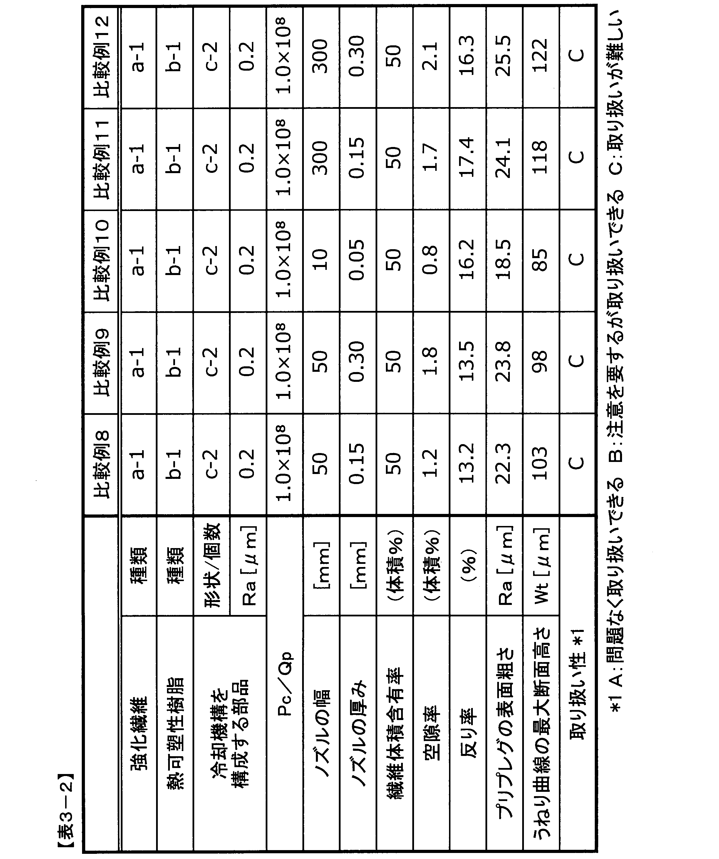
101 強化繊維
102 ボビン
103 糸道ガイド
104 槽
105 フィーダー
106 排出口
107 熱可塑性樹脂組成物
108 冷却機構
109 引取ロール
110 テープ状プリプレグ
111 巻取ロール
200 ローラー形状の部品を1個用いた場合のローラー形状の部品によるテープ状プリプレグ抱き構造の冷却機構
201 テープ状プリプレグ
202 ローラー形状の部品
203 ローラー形状の部品を2個用いた場合のローラー形状の部品によるテープ状プリプレグ抱き構造の冷却機構
204 ローラー形状の部品を4個用いた場合のローラー形状の部品によるテープ状プリプレグ抱き構造の冷却機構
300 ローラー形状の部品を2個用いた場合のローラー形状の部品によるテープ状プリプレグ挟持構造の冷却機構
301 テープ状プリプレグ
302 ローラー形状の部品
303 ローラー形状の部品を4個用いた場合のローラー形状の部品によるテープ状プリプレグ挟持構造の冷却機構
400 プレート形状の部品を1個用いた場合のプレート形状の部品によるテープ状プリプレグ挟持構造の冷却機構
401 テープ状プリプレグ
402 プレート形状の部品
403 プレート形状の部品を2個用いた場合のプレート形状の部品によるテープ状プリプレグ挟持構造の冷却機構
404 プレート形状の部品 を4個用いた場合のプレート形状の部品によるテープ状プリプレグ挟持構造の冷却機構
500 ローラー形状の部品と、プレート形状の部品とをそれぞれ1個ずつ用いた場合の冷却機構
501 テープ状プリプレグ
502 ローラー形状の部品
503 プレート形状の部品
504 ローラー形状の部品と、プレート形状の部品とをそれぞれ2個ずつ用いた場合の冷却機構
Claims (22)
- 一方向に配向した強化繊維、及び、熱可塑性樹脂組成物を含むテープ状プリプレグであって、
前記強化繊維の配向方向と直交する方向における、JIS B 0601:2013に基づいて測定される算術平均粗さ(Ra)が0.1~10μm、 かつ、下記(i)~(iii)によって求められる反り率が5%以下である、テープ状プリプレグ。
(i)繊維配向方向の長さが100mmの前記テープ状プリプレグを平面上に端部が上方に浮く向きで静置する。
(ii)前記上方に浮いたテープの右端の最も高い位置から平面までの垂直距離をa、左端の最も高い位置から平面までの垂直距離をbとし、aとbの算術平均値を反り長と規定する。
(iii)下式で反り率を算出する。
反り率(%)=反り長(mm)/100(mm)×100 - 厚みが0.05~15mmである、請求項1に記載のテープ状プリプレグ。
- 前記強化繊維の繊維体積含有率が30~70%である、請求項1または2に記載のテープ状プリプレグ。
- 空隙率が5体積%以下である、請求項1~3のいずれかに記載のテープ状プリプレグ。
- 前記熱可塑性樹脂組成物がポリアミド樹脂組成物である、請求項1~4のいずれかに記載のテープ状プリプレグ。
- 前記強化繊維が炭素繊維である、請求項1~5のいずれかに記載のテープ状プリプレグ。
- 前記強化繊維の配向方向と直交する方向における、JIS B 0601:2013に基づいて測定されるうねり曲線の最大断面高さ(Wt)が80μm以下である、請求項1~6のいずれかに記載のテープ状プリプレグ。
- 一方向に配向した強化繊維、及び、熱可塑性樹脂組成物を含むテープ状プリプレグであって、
前記強化繊維の配向方向と直交する方向における、JIS B 0601:2013に基づいて測定されるうねり曲線の最大断面高さ(Wt)が80μm以下、かつ、下記(i)~(iii)によって求められる反り率が5%以下である、テープ状プリプレグ。
(i)繊維配向方向の長さが100mmの前記テープ状プリプレグを平面上に端部が上方に浮く向きで静置する。
(ii)前記上方に浮いたテープの右端の最も高い位置から平面までの垂直距離をa、左端の最も高い位置から平面までの垂直距離をbとし、aとbの算術平均値を反り長と規定する。
(iii)下式で反り率を算出する。
反り率(%)=反り長(mm)/100(mm)×100 - 溶融状態の熱可塑性樹脂組成物を、入口部及び出口部を有する槽内で、前記槽の入口部から導入された複数の連続強化繊維に含浸させ、
前記槽の出口部を通過させた後に、冷却機構を通過させて、前記熱可塑性樹脂組成物と複数の連続強化繊維からなるテープ状プリプレグを製造する方法において、
前記冷却機構の吸熱能力をPc[W]として、前記冷却機構を1秒間に通過する前記テープ状プリプレグの体積をQp[m3/s]とした際に、前記PcとQpとが下記(A)式を満たす、テープ状プリプレグの製造方法。
2.8×10⁸≦Pc/Qp≦23.2×108・・・(A) - 前記冷却機構を構成する冷却用の部品として、ローラー形状のものを1個又は複数個用いる、請求項8に記載のテープ状プリプレグの製造方法。
- 前記冷却機構を構成する冷却用の部品として、プレート形状のものを1個又は複数個用いる、請求項8に記載のテープ状プリプレグの製造方法。
- 前記冷却機構を構成する冷却用の部品として、ローラー形状のもの及びプレート形状のものをそれぞれ1個又は複数個ずつ用いる、請求項8に記載のテープ状プリプレグの製造方法。
- 前記冷却機構を構成する冷却用の部品の温度を変更可能である、請求項8~11のいずれかに記載のテープ状プリプレグの製造方法。
- 前記冷却機構を構成する冷却用の部品を複数個使用し、
前記冷却機構を構成する各冷却用の部品の温度をそれぞれ独立に変更可能である、請求項12に記載のテープ状プリプレグの製造方法。 - 前記冷却機構が対向するように設置された少なくとも2つの冷却用の部品を有し、その部品の間を前記テープ状プリプレグが通過する、請求項8~13のいずれかに記載のテープ状プリプレグの製造方法。
- 前記2つの冷却用の部品の間の距離を任意に規定可能である、請求項15に記載のテープ状プリプレグの製造方法。
- 前記2つの冷却用の部品を規定の位置に固定する力を任意に設定可能である、請求項15または16に記載のテープ状プリプレグの製造方法。
- 前記冷却機構を通過して固化したテープ状プリプレグを巻き取る、請求項9~17のいずれかに記載のテープ状プリプレグの製造方法。
- 複数のテープ状プリプレグを並列して、同時に走行させる、請求項9~18のいずれかに記載のテープ状プリプレグの製造方法。
- 前記熱可塑性樹脂組成物が含浸した複数の連続強化繊維は、前記槽の出口部を通過する際に、走行方向に沿って一方向に配列される、請求項9~19のいずれかに記載のテープ状プリプレグの製造方法。
- 前記熱可塑性樹脂組成物がポリアミド樹脂組成物である、請求項9~20のいずれかに記載のテープ状プリプレグの製造方法。
- 前記連続強化繊維の材料が炭素繊維である、請求項9~21のいずれかに記載のテープ状プリプレグの製造方法。
Priority Applications (5)
| Application Number | Priority Date | Filing Date | Title |
|---|---|---|---|
| CN201880081972.4A CN111491769B (zh) | 2017-12-22 | 2018-12-13 | 带状预浸料及其制造方法 |
| US16/772,502 US11938655B2 (en) | 2017-12-22 | 2018-12-13 | Tape-shaped prepreg and a method for production thereof |
| EP18892541.6A EP3730264B1 (en) | 2017-12-22 | 2018-12-13 | Tape-shaped prepreg and production method therefor |
| KR1020207018534A KR102621342B1 (ko) | 2017-12-22 | 2018-12-13 | 테이프형 프리프레그 및 그의 제조 방법 |
| JP2019513859A JPWO2019124203A1 (ja) | 2017-12-22 | 2018-12-13 | テープ状プリプレグ及びその製造方法 |
Applications Claiming Priority (4)
| Application Number | Priority Date | Filing Date | Title |
|---|---|---|---|
| JP2017-245913 | 2017-12-22 | ||
| JP2017245913 | 2017-12-22 | ||
| JP2017-245914 | 2017-12-22 | ||
| JP2017245914 | 2017-12-22 |
Publications (1)
| Publication Number | Publication Date |
|---|---|
| WO2019124203A1 true WO2019124203A1 (ja) | 2019-06-27 |
Family
ID=66994666
Family Applications (1)
| Application Number | Title | Priority Date | Filing Date |
|---|---|---|---|
| PCT/JP2018/045826 Ceased WO2019124203A1 (ja) | 2017-12-22 | 2018-12-13 | テープ状プリプレグ及びその製造方法 |
Country Status (6)
| Country | Link |
|---|---|
| US (1) | US11938655B2 (ja) |
| EP (1) | EP3730264B1 (ja) |
| JP (1) | JPWO2019124203A1 (ja) |
| KR (1) | KR102621342B1 (ja) |
| CN (1) | CN111491769B (ja) |
| WO (1) | WO2019124203A1 (ja) |
Cited By (3)
| Publication number | Priority date | Publication date | Assignee | Title |
|---|---|---|---|---|
| JP2022150747A (ja) * | 2021-03-26 | 2022-10-07 | 帝人株式会社 | プリプレグ、プリプレグの製造方法、スリットプリプレグ、積層基材及び繊維強化複合材料 |
| JP2023539692A (ja) * | 2020-08-28 | 2023-09-15 | トウレ アドバンスト コンポジッツ | 改善された加工性を有するudテープおよびその製造方法 |
| JP2023539952A (ja) * | 2020-08-28 | 2023-09-20 | トウレ アドバンスト コンポジッツ | 改善された加工性および粗面を有するudテープならびにその製造方法 |
Families Citing this family (2)
| Publication number | Priority date | Publication date | Assignee | Title |
|---|---|---|---|---|
| US11938688B2 (en) * | 2018-12-18 | 2024-03-26 | Resonac Corporation | Laminate, printed wiring board, semiconductor package, and method for manufacturing laminate |
| CN112776218B (zh) * | 2021-01-29 | 2025-09-30 | 山东非金属材料研究所 | 一种导电微纳米材料改性预浸料连续化制备装置 |
Citations (10)
| Publication number | Priority date | Publication date | Assignee | Title |
|---|---|---|---|---|
| JPS5626660B2 (ja) | 1972-08-12 | 1981-06-19 | ||
| JPH0631821A (ja) * | 1992-07-14 | 1994-02-08 | Ube Ind Ltd | 熱可塑性複合材料の製造方法 |
| JP2004291558A (ja) | 2003-03-28 | 2004-10-21 | Toray Ind Inc | 繊維強化熱可塑性樹脂製射出成形品およびその製造方法 |
| JP2007076224A (ja) * | 2005-09-15 | 2007-03-29 | Toho Tenax Co Ltd | 炭素繊維強化熱可塑性樹脂テープの製造装置 |
| JP2007118216A (ja) * | 2005-10-25 | 2007-05-17 | Toho Tenax Co Ltd | 炭素繊維強化熱可塑性樹脂テープ及びその製造方法 |
| JP2013159723A (ja) * | 2012-02-07 | 2013-08-19 | Toray Ind Inc | プリプレグおよびその製造方法 |
| JP2015221867A (ja) * | 2014-05-23 | 2015-12-10 | 東レ株式会社 | プリプレグ及びその製造方法ならびに炭素繊維強化複合材料 |
| WO2016009735A1 (ja) * | 2014-07-16 | 2016-01-21 | 株式会社神戸製鋼所 | 繊維強化熱可塑性樹脂テープの製造装置及び製造方法 |
| JP2016083923A (ja) | 2014-07-16 | 2016-05-19 | 株式会社神戸製鋼所 | 繊維強化熱可塑性樹脂テープの製造装置及び製造方法 |
| JP2016216654A (ja) * | 2015-05-22 | 2016-12-22 | 株式会社神戸製鋼所 | テープ状プリプレグ及び繊維強化成形体 |
Family Cites Families (23)
| Publication number | Priority date | Publication date | Assignee | Title |
|---|---|---|---|---|
| JPH0598042A (ja) * | 1991-10-03 | 1993-04-20 | Toray Ind Inc | ポリ−フエニレンスルフイド樹脂含浸繊維シート |
| US5462618A (en) * | 1993-03-23 | 1995-10-31 | Bell Helicopter Textron Inc. | Continuous process of making unidirectional graphite fiber reinforced pultruded rods having minimal fiber waviness |
| DE69427258T2 (de) * | 1993-03-31 | 2001-12-06 | Toray Industries, Inc. | Mit harz imprägnierte faserplatte |
| JP4000253B2 (ja) * | 2001-11-05 | 2007-10-31 | 三菱レイヨン株式会社 | 担持シート付きプリプレグ、及びプリプレグ用担持シート |
| JP2004051660A (ja) * | 2002-07-16 | 2004-02-19 | Toray Ind Inc | プリプレグおよびその製造方法 |
| JP2005161797A (ja) * | 2003-12-05 | 2005-06-23 | Toray Ind Inc | プリプレグの製造方法および製造装置 |
| GB0613834D0 (en) * | 2006-07-12 | 2006-08-23 | Hexcel Composites Ltd | Composite material assembly |
| EP2138530B1 (en) * | 2007-03-20 | 2017-03-29 | Toray Industries, Inc. | Molding material, prepreg, fiber-reinforced composite material, and process for production of fiber-reinforced molding base material |
| JP2008246782A (ja) * | 2007-03-29 | 2008-10-16 | Teijin Techno Products Ltd | 繊維強化熱可塑性樹脂テープ製造装置及び繊維強化熱可塑性樹脂テープの製造方法 |
| GB2471319A (en) * | 2009-06-26 | 2010-12-29 | Hexcel Composites Ltd | Manufacturing composite materials containing conductive fibres |
| EP2589475B1 (en) | 2010-06-30 | 2020-06-17 | Toray Industries, Inc. | Process and apparatus for producing sheet-shaped prepreg |
| US8551380B2 (en) * | 2010-11-12 | 2013-10-08 | The Boeing Company | Method of laying up prepreg plies on contoured tools using a deformable carrier film |
| US9074064B2 (en) * | 2010-12-13 | 2015-07-07 | Toray Industries, Inc. | Carbon fiber prepreg, method for producing same and carbon fiber reinforced composite material |
| US20130164498A1 (en) * | 2011-12-21 | 2013-06-27 | Adc Acquisition Company | Thermoplastic composite prepreg for automated fiber placement |
| CN104684975B (zh) * | 2012-09-28 | 2016-11-23 | 东丽株式会社 | 预浸料坯和碳纤维增强复合材料 |
| CN103847111B (zh) * | 2012-12-01 | 2016-05-11 | 北京化工大学 | 一种连续纤维增强热塑性树脂片材的成型方法 |
| FR3017329B1 (fr) | 2014-02-13 | 2016-07-29 | Arkema France | Procede de fabrication d'un materiau fibreux pre-impregne de polymere thermoplastique en lit fluidise |
| CN105619842A (zh) * | 2014-10-31 | 2016-06-01 | 林世平 | 连续纤维增强热塑性预浸带的二合一浸渍生产法及其设备 |
| ES2842278T3 (es) * | 2014-11-03 | 2021-07-13 | Cytec Ind Inc | Unión de materiales compuestos |
| JP6650228B2 (ja) * | 2015-08-17 | 2020-02-19 | 株式会社神戸製鋼所 | 繊維強化熱可塑性樹脂テープの製造装置及び製造方法 |
| CN106113531B (zh) * | 2016-06-30 | 2018-09-18 | 宁波华业材料科技有限公司 | 一种防卷翘cfrt单向带复合片材的生产工艺 |
| CN106626444A (zh) * | 2016-07-27 | 2017-05-10 | 山东极威新材料科技有限公司 | 一种连续纤维增强热塑性复合材料拉挤型材的生产工艺 |
| TWI848068B (zh) * | 2019-03-08 | 2024-07-11 | 日商Toto股份有限公司 | 具備釉藥層的物品及其製造方法 |
-
2018
- 2018-12-13 JP JP2019513859A patent/JPWO2019124203A1/ja active Pending
- 2018-12-13 CN CN201880081972.4A patent/CN111491769B/zh active Active
- 2018-12-13 EP EP18892541.6A patent/EP3730264B1/en active Active
- 2018-12-13 US US16/772,502 patent/US11938655B2/en active Active
- 2018-12-13 WO PCT/JP2018/045826 patent/WO2019124203A1/ja not_active Ceased
- 2018-12-13 KR KR1020207018534A patent/KR102621342B1/ko active Active
Patent Citations (10)
| Publication number | Priority date | Publication date | Assignee | Title |
|---|---|---|---|---|
| JPS5626660B2 (ja) | 1972-08-12 | 1981-06-19 | ||
| JPH0631821A (ja) * | 1992-07-14 | 1994-02-08 | Ube Ind Ltd | 熱可塑性複合材料の製造方法 |
| JP2004291558A (ja) | 2003-03-28 | 2004-10-21 | Toray Ind Inc | 繊維強化熱可塑性樹脂製射出成形品およびその製造方法 |
| JP2007076224A (ja) * | 2005-09-15 | 2007-03-29 | Toho Tenax Co Ltd | 炭素繊維強化熱可塑性樹脂テープの製造装置 |
| JP2007118216A (ja) * | 2005-10-25 | 2007-05-17 | Toho Tenax Co Ltd | 炭素繊維強化熱可塑性樹脂テープ及びその製造方法 |
| JP2013159723A (ja) * | 2012-02-07 | 2013-08-19 | Toray Ind Inc | プリプレグおよびその製造方法 |
| JP2015221867A (ja) * | 2014-05-23 | 2015-12-10 | 東レ株式会社 | プリプレグ及びその製造方法ならびに炭素繊維強化複合材料 |
| WO2016009735A1 (ja) * | 2014-07-16 | 2016-01-21 | 株式会社神戸製鋼所 | 繊維強化熱可塑性樹脂テープの製造装置及び製造方法 |
| JP2016083923A (ja) | 2014-07-16 | 2016-05-19 | 株式会社神戸製鋼所 | 繊維強化熱可塑性樹脂テープの製造装置及び製造方法 |
| JP2016216654A (ja) * | 2015-05-22 | 2016-12-22 | 株式会社神戸製鋼所 | テープ状プリプレグ及び繊維強化成形体 |
Non-Patent Citations (1)
| Title |
|---|
| See also references of EP3730264A4 |
Cited By (5)
| Publication number | Priority date | Publication date | Assignee | Title |
|---|---|---|---|---|
| JP2023539692A (ja) * | 2020-08-28 | 2023-09-15 | トウレ アドバンスト コンポジッツ | 改善された加工性を有するudテープおよびその製造方法 |
| JP2023539952A (ja) * | 2020-08-28 | 2023-09-20 | トウレ アドバンスト コンポジッツ | 改善された加工性および粗面を有するudテープならびにその製造方法 |
| JP7644242B2 (ja) | 2020-08-28 | 2025-03-11 | トウレ アドバンスト コンポジッツ | 改善された加工性を有するudテープおよびその製造方法 |
| JP7747752B2 (ja) | 2020-08-28 | 2025-10-01 | トウレ アドバンスト コンポジッツ | 改善された加工性および粗面を有するudテープならびにその製造方法 |
| JP2022150747A (ja) * | 2021-03-26 | 2022-10-07 | 帝人株式会社 | プリプレグ、プリプレグの製造方法、スリットプリプレグ、積層基材及び繊維強化複合材料 |
Also Published As
| Publication number | Publication date |
|---|---|
| KR102621342B1 (ko) | 2024-01-08 |
| KR20200098551A (ko) | 2020-08-20 |
| EP3730264B1 (en) | 2022-08-24 |
| EP3730264A4 (en) | 2021-09-01 |
| EP3730264A1 (en) | 2020-10-28 |
| US11938655B2 (en) | 2024-03-26 |
| JPWO2019124203A1 (ja) | 2020-10-22 |
| CN111491769B (zh) | 2022-07-22 |
| CN111491769A (zh) | 2020-08-04 |
| US20200385540A1 (en) | 2020-12-10 |
Similar Documents
| Publication | Publication Date | Title |
|---|---|---|
| WO2019124203A1 (ja) | テープ状プリプレグ及びその製造方法 | |
| JP7234632B2 (ja) | 一方向に配向したテープ状プリプレグ、およびその成形品 | |
| JP6496833B2 (ja) | 一方向繊維強化テープを作製するための方法 | |
| JP7140131B2 (ja) | 離型シート付き多層構造プリプレグ、プリプレグロール、プリプレグテープおよび複合材料 | |
| KR102300301B1 (ko) | 도포액 함침 강화 섬유 패브릭, 시트상 일체물, 프리프레그, 프리프레그 테이프 및 섬유 강화 복합 재료의 제조 방법 | |
| JP5614187B2 (ja) | 複合強化繊維束の製造方法およびそれを用いた成形材料 | |
| WO2013129541A1 (ja) | 繊維強化プラスチック成形体用シート及びその成形体 | |
| CN105385183A (zh) | 包含单向连续纤维和热塑性树脂的复合材料 | |
| JP5494375B2 (ja) | 複合強化繊維束の製造方法およびそれを用いた成形材料 | |
| US12172341B2 (en) | Method of producing thermoplastic resin-impregnated sheet-shaped reinforcing fiber bundle | |
| JP7243629B2 (ja) | プリプレグの製造方法および製造装置 | |
| KR20190095293A (ko) | 분무에 의해 열가소성 폴리머로 예비 함침된 섬유성 재료를 제조하기 위한 방법 | |
| WO2016136793A1 (ja) | 樹脂供給材料、プリフォーム、および繊維強化樹脂の製造方法 | |
| CN104974521A (zh) | 预浸料、碳纤维增强复合材料及机械手 | |
| US11208535B2 (en) | Production method for prepreg, and production method for fiber-reinforced composite material | |
| JP4152230B2 (ja) | 複合基材の製造方法 | |
| JP6946648B2 (ja) | プリプレグの製造方法 | |
| JP2018104537A (ja) | 基材 | |
| JP2020028844A (ja) | 塗液含浸強化繊維シートおよびシート状一体物の製造方法、塗工装置 | |
| WO2012067104A1 (ja) | 炭素繊維強化樹脂複合材及びその製造方法 |
Legal Events
| Date | Code | Title | Description |
|---|---|---|---|
| ENP | Entry into the national phase |
Ref document number: 2019513859 Country of ref document: JP Kind code of ref document: A |
|
| 121 | Ep: the epo has been informed by wipo that ep was designated in this application |
Ref document number: 18892541 Country of ref document: EP Kind code of ref document: A1 |
|
| NENP | Non-entry into the national phase |
Ref country code: DE |
|
| ENP | Entry into the national phase |
Ref document number: 20207018534 Country of ref document: KR Kind code of ref document: A |
|
| ENP | Entry into the national phase |
Ref document number: 2018892541 Country of ref document: EP Effective date: 20200722 |