WO2019124236A1 - 送信方法、受信方法、送信装置、および受信装置 - Google Patents
送信方法、受信方法、送信装置、および受信装置 Download PDFInfo
- Publication number
- WO2019124236A1 WO2019124236A1 PCT/JP2018/046029 JP2018046029W WO2019124236A1 WO 2019124236 A1 WO2019124236 A1 WO 2019124236A1 JP 2018046029 W JP2018046029 W JP 2018046029W WO 2019124236 A1 WO2019124236 A1 WO 2019124236A1
- Authority
- WO
- WIPO (PCT)
- Prior art keywords
- information
- base station
- terminal
- signal
- ssid
- Prior art date
- Legal status (The legal status is an assumption and is not a legal conclusion. Google has not performed a legal analysis and makes no representation as to the accuracy of the status listed.)
- Ceased
Links
Images


Classifications
-
- H—ELECTRICITY
- H04—ELECTRIC COMMUNICATION TECHNIQUE
- H04B—TRANSMISSION
- H04B10/00—Transmission systems employing electromagnetic waves other than radio-waves, e.g. infrared, visible or ultraviolet light, or employing corpuscular radiation, e.g. quantum communication
- H04B10/50—Transmitters
- H04B10/516—Details of coding or modulation
- H04B10/54—Intensity modulation
- H04B10/541—Digital intensity or amplitude modulation
-
- H—ELECTRICITY
- H04—ELECTRIC COMMUNICATION TECHNIQUE
- H04B—TRANSMISSION
- H04B10/00—Transmission systems employing electromagnetic waves other than radio-waves, e.g. infrared, visible or ultraviolet light, or employing corpuscular radiation, e.g. quantum communication
- H04B10/11—Arrangements specific to free-space transmission, i.e. transmission through air or vacuum
- H04B10/114—Indoor or close-range type systems
- H04B10/116—Visible light communication
-
- H—ELECTRICITY
- H04—ELECTRIC COMMUNICATION TECHNIQUE
- H04B—TRANSMISSION
- H04B10/00—Transmission systems employing electromagnetic waves other than radio-waves, e.g. infrared, visible or ultraviolet light, or employing corpuscular radiation, e.g. quantum communication
- H04B10/50—Transmitters
- H04B10/508—Pulse generation, e.g. generation of solitons
-
- H—ELECTRICITY
- H04—ELECTRIC COMMUNICATION TECHNIQUE
- H04B—TRANSMISSION
- H04B10/00—Transmission systems employing electromagnetic waves other than radio-waves, e.g. infrared, visible or ultraviolet light, or employing corpuscular radiation, e.g. quantum communication
- H04B10/60—Receivers
- H04B10/66—Non-coherent receivers, e.g. using direct detection
-
- H—ELECTRICITY
- H04—ELECTRIC COMMUNICATION TECHNIQUE
- H04B—TRANSMISSION
- H04B10/00—Transmission systems employing electromagnetic waves other than radio-waves, e.g. infrared, visible or ultraviolet light, or employing corpuscular radiation, e.g. quantum communication
- H04B10/11—Arrangements specific to free-space transmission, i.e. transmission through air or vacuum
-
- H—ELECTRICITY
- H04—ELECTRIC COMMUNICATION TECHNIQUE
- H04B—TRANSMISSION
- H04B10/00—Transmission systems employing electromagnetic waves other than radio-waves, e.g. infrared, visible or ultraviolet light, or employing corpuscular radiation, e.g. quantum communication
- H04B10/50—Transmitters
- H04B10/516—Details of coding or modulation
- H04B10/5161—Combination of different modulation schemes
Definitions
- the present disclosure relates to a transmission method, a reception method, a transmission apparatus, and a reception apparatus.
- GPS Global Positioning System
- a terminal receives a modulated signal transmitted from a satellite and estimates its own location by performing positioning calculation.
- the terminal receives the radio wave transmitted by the satellite (for example, indoors)
- the terminal is from an access point (AP (access point)) of a wireless LAN (Local Area Network).
- AP access point
- LAN Local Area Network
- the terminal does not hold information such as the service set identifier (SSID) of the access point to be accessed, for example, it is appropriate to which access point the terminal should connect to among the plurality of access points in the vicinity. It is not easy to judge. Therefore, for example, when the terminal connects to the access point in order to obtain information such as its own location, there is a possibility that the terminal may connect to an access point having an unsecured SSID, and there is a threat such as information leakage.
- SSID service set identifier
- One aspect of the present disclosure promotes to provide, for example, a transmission method and the like that can securely obtain information and the like used by a terminal to identify an access point to be connected.
- a light source is turned on at a first luminance in a first period, and a second luminance and a third luminance lower than the second luminance in a second period. And alternately turning on the light source to cause the light source to transmit an optical signal.
- a receiving method receives light of a first brightness from a light source in a first period, and has light of a second brightness and a brightness lower than the second brightness in a second period.
- the light signal transmitted from the light source is received by alternately receiving light of the third luminance, and analysis information is output by analyzing data based on the light signal.
- a terminal can obtain information securely.
- FIG. 1 is a diagram for explaining the principle of line scan sampling.
- FIG. 2 is a view showing an example of a captured image when the exposure time is long.
- FIG. 3 is a view showing an example of a captured image when the exposure time is short.
- FIG. 4A is a diagram for explaining 4 PPM.
- FIG. 4B is a diagram for explaining the Manchester coding scheme.
- FIG. 5 is a view showing a configuration example of a visible light communication system.
- FIG. 6 is a diagram showing an example of configuration of the communication system according to the first embodiment.
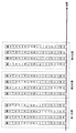
- FIG. 7 is a diagram showing an example of a frame configuration according to the first embodiment.
- FIG. 8 is a diagram showing the positional relationship between a device and a terminal according to the second embodiment.
- FIG. 1 is a diagram for explaining the principle of line scan sampling.
- FIG. 2 is a view showing an example of a captured image when the exposure time is long.
- FIG. 3 is a view showing an example of a captured image
- FIG. 9 is a diagram showing an example of configuration of a communication system according to Embodiment 3.
- FIG. 10 is a diagram showing a display example of the display unit according to the third embodiment.
- FIG. 11 is a diagram illustrating an example of a frame configuration of a modulated signal transmitted by the first device according to the third embodiment.
- FIG. 12 is a diagram showing an example of a frame configuration of a modulated signal transmitted by the base station according to the third embodiment.
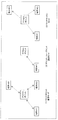
- FIG. 13 is a flowchart of an example of processing in the communication system according to the third embodiment.
- FIG. 14 is a diagram showing a display example of the display unit according to the third embodiment.
- FIG. 15 is a diagram showing an example of configuration of a communication system according to Embodiment 4.
- FIG. 10 is a diagram showing a display example of the display unit according to the third embodiment.
- FIG. 11 is a diagram illustrating an example of a frame configuration of a modulated signal transmitted by the first device according to the third embodiment.
- FIG. 16 is a diagram showing an example of a frame configuration of a modulated signal transmitted by the first device according to the fourth embodiment.
- FIG. 17 is a diagram showing an example of a frame configuration of a modulated signal transmitted by the radio apparatus of the terminal according to the fourth embodiment.
- FIG. 18 is a flowchart of an example of processing in the communication system according to the fourth embodiment.
- FIG. 19 is a diagram showing an example of configuration of a communication system according to Embodiment 5.
- FIG. 20 is a diagram illustrating an example of a frame configuration of a modulated signal including an SSID, which is transmitted by the third device according to the fifth embodiment.
- FIG. 21 is a diagram illustrating an example of a frame configuration of a modulated signal including an encryption key, which is transmitted by the third device according to the fifth embodiment.
- FIG. 22 is a flowchart of an example of processing in the communication system according to the fifth embodiment.
- FIG. 23 is a flowchart illustrating another example of processing in the communication system according to Embodiment 5.
- FIG. 24 is a diagram showing an example of a space in which the communication system according to Embodiment 5 is arranged.
- FIG. 25 is a diagram showing an example of configuration of a communication system according to a sixth embodiment.
- FIG. 26 is a flowchart of an example of processing in the communication system according to Embodiment 6.
- FIG. 27 is a diagram of an exemplary configuration of a communication system according to a seventh embodiment.
- FIG. 28 is a diagram illustrating an example of a frame configuration of a modulated signal transmitted by the fifth device according to the seventh embodiment.
- FIG. 29 is a diagram showing an example of a frame configuration of a modulated signal transmitted by the fifth device according to the seventh embodiment.
- FIG. 30 is a diagram showing an example of a frame configuration of a modulated signal transmitted by the fifth device according to the seventh embodiment.
- FIG. 31 is a diagram illustrating an example of a frame transmission method by the fifth device according to the seventh embodiment.
- FIG. 32 is a diagram showing an example of a space in which the communication system according to Embodiment 7 is arranged.
- FIG. 33 is a flowchart of a process example of the communication system according to the seventh embodiment.
- FIG. 34 is a diagram showing an exemplary configuration of a communication apparatus according to an eighth embodiment.
- FIG. 35 is a diagram showing another configuration example of the communication apparatus according to the eighth embodiment.
- FIG. 36 is a diagram showing a first configuration example of the light receiving device according to the eighth embodiment.
- FIG. 37 is a diagram showing a first configuration example of the light reception signal processing unit according to the eighth embodiment.
- FIG. 38 is a diagram of a second configuration example of the light reception signal processing unit according to the eighth embodiment.
- FIG. 39 is a diagram showing an example of control of the image sensor in the eighth embodiment.
- FIG. 40 is a diagram showing a third configuration example of the light reception signal processing unit according to the eighth embodiment.
- FIG. 41 is a diagram showing a second configuration example of the light receiving device according to the eighth embodiment.
- FIG. 42 is a diagram showing an example in which line scan sampling is performed in parallel in a plurality of areas.
- FIG. 43 is a diagram of an example of a physical configuration of a control unit according to the eighth embodiment.
- FIG. 44 is a diagram of an exemplary configuration of a control unit according to the eighth embodiment.
- FIG. 45 is a diagram illustrating another configuration example of the control unit according to the eighth embodiment.
- FIG. 46 is a first diagram illustrating communication control based on an acquired image according to the eighth embodiment.
- FIG. 47 is a second diagram for explaining communication control based on an acquired image according to the eighth embodiment.
- FIG. 48 is a third diagram illustrating communication control based on an acquired image according to the eighth embodiment.
- FIG. 49 is a fourth diagram illustrating communication control based on an acquired image according to the eighth embodiment.
- FIG. 50 is a fifth diagram illustrating communication control based on an acquired image according to the eighth embodiment.
- FIG. 51 is a sixth diagram illustrating communication control based on an acquired image according to the eighth embodiment.
- FIG. 52 is a diagram showing an example of a configuration of another communication system that performs optical communication.
- FIG. 53 is a diagram of a configuration example of the transmission device and the reception device according to the tenth embodiment.
- FIG. 54 is a diagram of a configuration example of a transmission apparatus and a reception apparatus according to the tenth embodiment.
- FIG. 55 is a diagram showing an example of a frame configuration of the light modulation signal according to the tenth embodiment.
- FIG. 56 is a diagram showing an example of a reception state in the receiving apparatus according to the tenth embodiment.
- FIG. 57 is a diagram showing an example of symbol configurations according to the tenth embodiment.
- FIG. 58 is a diagram showing another example of symbol configurations according to the tenth embodiment.
- FIG. 59 is a diagram showing another example of the reception state in the receiving apparatus according to the tenth embodiment.
- FIG. 60 is a diagram showing another example of the reception state in the receiving apparatus according to the tenth embodiment.
- FIG. 61 is a diagram showing another example of symbol configurations according to Embodiment 10.
- FIG. FIG. 62 is a diagram illustrating another example of symbol configurations according to the tenth embodiment.
- FIG. 63 is a diagram showing another example of symbol configurations according to Embodiment 11.
- FIG. 64 is a diagram showing an example of a configuration of a receiving apparatus according to an eleventh embodiment.
- FIG. 65 is a diagram showing another example of the configuration of the receiving apparatus according to the eleventh embodiment.
- FIG. 66 is a diagram showing another example of the configuration of the receiving apparatus according to the eleventh embodiment.
- FIG. 67 is a diagram showing another example of the configuration of the reception apparatus according to the eleventh embodiment.
- FIG. 68 is a diagram showing an example of a configuration of a communication system according to Embodiment 12. 69 shows an example of recognition results according to Embodiment 12.
- FIG. FIG. 70 is a diagram showing another example of the configuration of the communication system according to Embodiment 12.
- FIG. 70 is a diagram showing another example of the configuration of the communication system according to Embodiment 12.
- FIG. 71A is a diagram illustrating an example of a configuration of a transmission apparatus according to a thirteenth embodiment.
- FIG. 71B is a diagram showing an example of a liquid crystal screen according to Embodiment 13.
- FIG. 72 is a diagram illustrating an example of use of the transmission apparatus according to Embodiment 13.
- FIG. 73 is a diagram showing an example of a configuration of a mirror according to a fourteenth embodiment.
- FIG. 74A is a diagram showing an example of luminance change in an information transmission period and a light lighting period according to the fifteenth embodiment.
- FIG. 74B is a diagram illustrating an example of a frame configuration according to Embodiment 15.
- FIG. 74C is a diagram showing an example of configuration of a communication system according to Embodiment 15.
- FIG. 75 is a diagram illustrating an example of a transmission device according to Embodiment 15 including the illumination light source and the communication light source.
- FIG. 76 is a diagram showing an example of a plurality of light sources provided in a car.
- FIG. 77 is a view showing an example of a plurality of light receiving units provided in a car.
- FIG. 78 is a diagram showing an example of a frame configuration of the light modulation signal.
- FIG. 79 is a diagram illustrating an example of relay of visible light communication.
- FIG. 80 is a diagram showing an example of a frame configuration of a light modulation signal transmitted by the transmission apparatus of the thirteenth embodiment.
- FIG. 81 is a diagram of a transmission device and a communication device according to a thirteenth embodiment.
- FIG. 82 is a diagram showing communication between the first communication device and the second communication device.
- FIG. 83 is a diagram showing an exemplary configuration of a communication apparatus.
- FIG. 84 is a diagram illustrating an example of timing when a training symbol is transmitted from each of a plurality of light sources.
- FIG. 85 is a diagram illustrating an example of reception timing of each of the plurality of light receiving units.
- FIG. 86 is a diagram showing a detailed configuration example of a transmission unit that does not perform precoding in the communication apparatus shown in FIG.
- FIG. 87 is a diagram showing a detailed configuration example of a transmission unit that implements precoding in the communication apparatus shown in FIG. 83.
- FIG. 88 is a diagram showing an example of the configuration of a light source.
- FIG. 90 is a diagram illustrating an example in which the access point performs selection of a light source and setting of parameters and the terminal performs selection of a light receiving unit.
- FIG. 91 is a diagram illustrating an example in which the access point transmits a training symbol for light source parameter.
- FIG. 92 is a diagram illustrating an example where the access point transmits a training symbol for each light source.
- FIG. 93 is a diagram showing a modification of training for optimizing the light source.
- FIG. 94 is a diagram showing an example in which the access point transmits “light source / light receiver selection and light source parameter training symbol”.
- FIG. 95 is a diagram illustrating three modes of communication and transmission.
- an optical communication system for transmitting and receiving a modulation signal as an optical signal is used.
- An image sensor such as a complementary metal oxide semiconductor (CMOS) sensor is mounted on a smartphone or a digital camera.
- CMOS complementary metal oxide semiconductor
- the image taken by the CMOS sensor does not necessarily reflect the scenery at exactly the same time as the whole.
- the shutter operation is performed row by row.
- the amount of light received by the sensor is read out line by line using a rolling shutter method. Therefore, control of the start and end of light reception is performed with a time difference for each line, in anticipation of the time required for reading. That is, the image captured by the CMOS sensor has a form in which a large number of lines with a time lag are gradually superimposed during the exposure period.
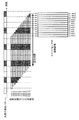
- speeding up of visible light signal reception is realized based on a method that focuses on the nature of the CMOS sensor. That is, in the first example of the visible light communication method, by utilizing the fact that the exposure time is slightly different for each line, as shown in FIG. It is possible to measure the brightness and color of the light source at each point in time, and to capture a signal modulated faster than the frame rate.
- CMOS Charge-Coupled Device
- CMOS organic
- the imaging setting at the time of imaging in the camera function moving image or still image photographing function
- the blinking does not appear as a stripe pattern along the exposure line.
- the exposure time is sufficiently longer than the flashing cycle of the light source, so as shown in FIG. 2, the change in luminance due to the flashing (light emission pattern) of the light source is averaged and the pixel value between the exposure lines is averaged. This is because the change is small and the image becomes almost uniform.
- the length of the exposure period is set to be slightly longer than the length of the minimum period in which the same light emission state continues, and the difference in the start time of the exposure period between adjacent exposure lines is the minimum period in which the same light emission state continues.
- the setting of the exposure period in lie scan sampling is not limited to this.
- the length of the exposure period may be set shorter than the length of the minimum period in which the same light emission state continues, or set to about twice the length of the minimum period in which the same light emission state continues.
- an optical communication system not only a system in which an optical signal is represented by a combination of rectangular waves shown in FIG. 4A, for example, but also a system in which an optical signal changes continuously may be used.
- the receiver using the optical communication scheme needs to use the start time or end time of the exposure period between the exposure lines that are temporally adjacent to the sampling rate required to receive and demodulate the light signal. The difference is set equal to or less than the sampling interval corresponding to the sampling rate.
- the length of the exposure period is set equal to or less than the sampling interval.
- the length of the exposure period may be set to 1.5 times or less of the sampling interval or may be set to 2 times or less.
- the exposure line is designed to be parallel to the long side direction of the image sensor.
- the frame rate is 30 fps (frames per second)
- more than 32400 samples per second can be obtained at a resolution of 1920 ⁇ 1080
- more than 64800 samples per second at a resolution of 3840 ⁇ 2160. Is obtained.
- the method for reading out a signal by controlling an exposure period for each pixel may be used in which the signal is read by controlling the exposure period in a group unit of a plurality of arranged pixels.
- a method may be used in which a signal is read a plurality of times from the same pixel in a period corresponding to one frame in a frame rate used for normal moving image shooting.
- LED light emitting diode
- LEDs are becoming popular as backlight sources for lighting or displays, and can be flashed at high speed.
- a light source used as a transmitter for visible light communication can not be blinked freely for visible light communication. If the change in luminance due to visible light communication can be recognized by human beings, the function of the original light source such as illumination is impaired. Therefore, it is required that the transmission signal be illuminated with a desired brightness so that flicker is not perceived by human eyes.
- 4PPM 4-Pulse Position Modulation
- 4PPM is more suitable than the Manchester coding method as a modulation method of visible light communication.
- the communication performance does not necessarily deteriorate. Therefore, depending on the application, there is a problem even when using a method that causes changes in luminance to be recognized by humans. There is not.
- the transmitter (light source) generates a modulation signal using a modulation method such as, for example, ASK (Amplitude Shift Keying) method, PSK (Phase Shift Keying) method, PAM (Pulse Amplitude Modulation), and turns on the light source. , May be irradiated.
- a modulation method such as, for example, ASK (Amplitude Shift Keying) method, PSK (Phase Shift Keying) method, PAM (Pulse Amplitude Modulation), and turns on the light source. , May be irradiated.
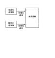
- the communication system for performing visible light communication includes at least a transmitter for transmitting (irradiating) an optical signal and a receiver for receiving (receiving) an optical signal.
- a transmitter for transmitting (irradiating) an optical signal for example, there are two types of transmitters: variable optical transmitters that change transmission content according to the video or content to be displayed, and fixed optical transmitters that continue to transmit fixed transmission content.
- the optical communication system can also be configured with a configuration in which either a variable light transmitter or a fixed light transmitter is present.
- the receiver may receive the optical signal from the transmitter, for example, obtain related information associated with the optical signal and provide it to the user.
- the communication system applicable to the optical communication demonstrated by the following embodiment is not limited to said system.
- the light emitting unit of the transmitter may transmit data using a plurality of light sources.
- the light receiving unit of the receiving apparatus may not be an image sensor such as a CMOS, but may be a communication method that can use a device capable of converting an optical signal such as a photodiode into an electrical signal, for example.
- a communication scheme using radio of a frequency other than visible light such as infrared light and ultraviolet light may be used.
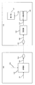
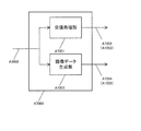
- FIG. 6 shows an example of the configuration of the device 100 and the terminal 150 in the present embodiment.
- the device 100 (corresponding to a transmitter for visible light communication) includes a visible light source such as a light emitting diode (LED), a light, or a light (collectively referred to as a light source).
- a visible light source such as a light emitting diode (LED), a light, or a light (collectively referred to as a light source).
- the device 100 may be referred to as a “first device”.
- the transmission unit 102 receives information on a place or information 101 on a position.
- the transmission unit 102 may receive the information 105 on time.
- the transmission unit 102 may receive both information on a place or information on a position 101 and information on a time 105.
- the transmission unit 102 receives information on a place or information on a position 101 and / or information on a time 105, generates a (light) modulation signal 103 based on these input signals, and outputs the modulation signal 103. . Then, the modulation signal 103 is transmitted from, for example, the light source 104.
- the information on location or the information on location 101 may be information on latitude and / or longitude of the location.
- the information “45 degrees north latitude, 135 degrees east longitude” may be used as the information 101 regarding the place or the position.
- the information on the place or the information on the position 101 may be information on an address.
- the information “Tokyo and Chiyoda Ward ⁇ Town 1-1-1,” may be used as the information 101 about the place or the position.
- the information on the place or the information on the position 101 may be information on a building, a facility, or the like.
- the information “Tokyo Tower” may be information 101 related to a place or information related to a position.
- the information on the place or the information on the position 101 may be information on the unique place / position of the thing installed in a building, a facility or the like.
- the information “A-3” may be information on a place or information 101 on a position.
- the terminal 150 (corresponding to a receiver for visible light communication) in FIG. 6 receives the modulated signal 103 transmitted from the first device 100.
- the light receiving unit (light receiving device) 151 is, for example, an image sensor such as a complementary metal oxide semiconductor (CMOS) or an organic CMOS.
- CMOS complementary metal oxide semiconductor
- the light receiving unit 151 receives light including the modulation signal transmitted from the first device 100, and outputs a reception signal 152.
- the received signal 152 output from the light receiving unit 151 may be a signal including information of an image and a moving image acquired by an image sensor, and performs other light-electric conversion (conversion from light to electric signal Output signal of the device).
- the light receiving unit 151 receives light from the light including the modulation signal.
- a "modulated signal for transmitting information" or "a signal of an image / moving image” and a "modulated signal for transmitting information” are obtained. It means to do.
- the method described above is an example of a method in which a device on the receiving side receives a modulated signal, and the method of receiving a modulated signal is not limited to these.
- the receiving unit 153 receives the received signal 152, performs processing such as demodulation and error correction decoding on the modulated signal included in the received signal 152, and outputs received data 154.
- the data analysis unit 155 receives the received data 154 and analyzes the received data 154 to estimate, for example, the location and position of the terminal 150, and outputs information 156 including at least the location and position information of the terminal 150.
- the display unit 157 receives the information 156, and displays the location and position of the terminal 150 from the location and position information of the terminal 150 included in the information 156.
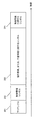
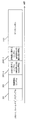
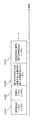
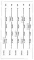
- FIG. 7 shows an example of a frame configuration of a modulated signal transmitted by the first device 100.
- the horizontal axis is time.
- the first device 100 transmits, for example, a preamble 201, and then transmits a control information symbol 202, a symbol 203 related to location information or position information, and a symbol 204 related to time information.
- the preamble 201 is a symbol for the terminal 150 that receives the modulated signal transmitted by the first device 100 to perform, for example, signal detection, time synchronization, frame synchronization, and the like.
- the control information symbol 202 is, for example, a symbol including data such as a method of forming a modulation signal, a method of an error correction coding method used, and a method of forming a frame.
- the symbol 203 relating to the location information or the location information is a symbol including the information relating to the location shown in FIG. 6 or the information 101 relating to the location.
- the frame may include symbols other than the symbols 201, 202, and 203.
- a symbol 204 related to time information may be included.
- the symbol 204 related to time information includes, for example, information 105 related to the time at which the first device 100 transmits a modulation signal.
- the configuration of the frame of the modulated signal transmitted by the first device 100 is not limited to that shown in FIG. 7, and the symbols included in the modulated signal are not limited to the configuration shown in FIG.
- the frame may include symbols containing other data and information.
- the terminal 150 capable of receiving this modulation signal is located far from the place where the first device 100 is present. Not in. Therefore, when the terminal 150 obtains the location and position information transmitted by the first device 100, the terminal 150 can easily obtain high-accuracy position information (without performing complicated signal processing). .
- the terminal 150 can transmit a modulated signal that the first device 100 transmits even in a situation where radio waves from GPS satellites are difficult to receive. By receiving, it is possible to obtain highly accurate position information safely.
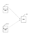
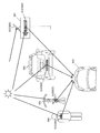
- a first 1-1 device 301-1 having the same configuration as the first device 100 shown in FIG. 6 transmits a modulation signal.
- the terminal 302 having a configuration similar to that of the terminal 150 shown in FIG. 6 receives the modulated signal transmitted by the 1-1st device 301-1, and, for example, information related to the 1-1st place and position, and Get information about time 1-1.
- a first device 1-2 having the same configuration as the first device 100 shown in FIG. 6 transmits a modulation signal.
- the terminal 302 receives the modulated signal transmitted by the 1-2nd device 301-2 and obtains, for example, information on the 1-2th location and position and information on the 1-2nd time.
- the terminal 302 uses the information related to the 1-1st place and position and the information related to the 1-2nd place and position to determine the 1-1st device 301-1 and 1-2th device in FIG. It is possible to calculate the distance between 301-2. Also, the terminal 302 can perform the terminal 302 and the 1-1 based on the information regarding the 1-1st time and, for example, the time when the terminal 302 receives the modulated signal transmitted by the 1-1 terminal 301-1. The distance to the device 301-1 of 1 can be calculated. Similarly, the terminal 302 and the first terminal 302 perform the first operation based on the information on the 1-2nd time and the time when the terminal 302 receives the modulated signal transmitted by the 1-2nd device 301-2, for example. It is possible to calculate the distance between the second device 301 and the second device 301-2.
- the terminal 302 can know the position of the 1-1st device 301-1 from the information on the 1-1st place and position.
- the terminal 302 can know the position of the 1-2nd device 301-2 from the information regarding the 1-2th place and position.
- the terminal 302 indicates “the distance between the 1-1st device 301-1 and the 1-2nd device 301-2”, and “the 1-1st device 301-1 and the terminal 302”. From the “distance” and “the distance between the 1-2nd device 301-2 and the terminal 302", the "1-1st device 301-1 and the 1-2nd device 301-2 and the terminal 302 are configured. Know the triangle to
- the terminal 302 can perform “the position of the 1-1st device 301-1”, “the position of the 1-2nd device 301-2”, and “the 1 st From the triangle formed by the device 301-2 and the terminal 302, the position of the terminal 302 can be calculated and obtained with high accuracy.
- geodetic survey method for the terminal 302 to obtain location and position information is not limited to the above description, and geodetic survey may be performed by any method.
- geodetic survey method there are triangulation, multilateral survey, trilateration, leveling, and the like.
- the terminal 302 estimates the position of the terminal 302 by obtaining the information as described above from the plurality of devices 301 equipped with light sources that transmit location information. Can be done with high accuracy.
- the terminal 302 when the device 301 having a light source for transmitting location information is installed at a location where satellite radio waves from the GPS are hard to receive, the terminal 302 Even in a situation where radio waves from the satellites are difficult to receive, by receiving the modulated signal transmitted by the device 301, highly accurate position information can be obtained safely.
- the terminal 302 receives the modulated signal transmitted by the two devices 301.
- the terminal 302 receives the modulated signal transmitted by more than two devices 301. The same can be carried out in the same case.
- the terminal 302 can calculate position information with high accuracy.
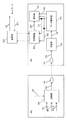
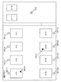
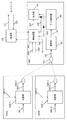
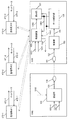
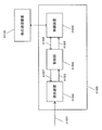
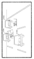
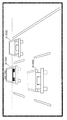
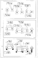
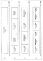
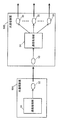
- FIG. 9 shows an example of the configuration of a device 400, a terminal 450, and a base station 470 (or AP (access point)) in communication with the terminal 450 in the present embodiment.
- the device 400 comprises, for example, a visible light source such as an LED, a light, a light source, or a light.
- a visible light source such as an LED
- a light such as an LED
- a light source such as a light
- a light such as a light
- a light source such as a light
- a light such as a light
- a light source such as a light
- the same reference numerals are given to configurations that operate in the same manner as the first device 100 shown in FIG. Further, in the terminal 450 shown in FIG. 9, the same reference numerals are given to configurations that operate in the same manner as the terminal 150 shown in FIG. 6.
- the transmitting unit 102 may, for example, information on location or information on location 101, information on SSID (service set identifier) 401 which is an identifier of the base station 470, information on access destination 401 -2 is input.
- the transmission unit 102 may receive the information 105 on time.
- the transmitting unit 102 receives information on location or information on location 101, information on SSID 401-1, information on access destination 401-2, and / or information on time 105 as input, and based on these input signals , (Light) modulation signal 103 is generated, and the modulation signal 103 is output. Then, the modulation signal 103 is transmitted from, for example, the light source 104.
- Information 401-1 related to the SSID is information indicating the SSID of the base station 470 in FIG.
- the first device 400 transmits the access to the base station 470 which is a safe access destination with respect to the terminal 450. Access can be provided. This enables terminal 450 in FIG. 9 to obtain information securely from base station 470.
- the first device 400 can limit terminals accessing the base station 470 to terminals located in a space where the optical signal transmitted (irradiated) by the first device 400 can be received.
- the terminal 450 may determine that the notified SSID is the SSID of a safe base station. In addition, the terminal 450 may separately perform a process of determining whether the notified SSID is secure. For example, the first device 400 transmits a predetermined identifier included in an optical signal, and the terminal 450 determines whether the notified SSID is the SSID of a secure base station based on the received identifier. May be Further, the terminal 450 selects the first device 400 with high security by using the characteristic of visible light without performing the process of determining whether or not the base station is a safe base station. The optical signal may be received from the first device 400 at 450 to obtain the SSID of the highly secure base station.
- the terminal 450 can use the first device 400 even if one or more base stations (or APs) other than the base station 470 exist, for example.
- the access point 470 accesses the base station 470 using the SSID obtained from the above to obtain information.
- Information on access destination 401-2 is information on an access destination to obtain information after the terminal 450 accesses the base station 470. A specific operation example of the present embodiment will be described later.
- the information 401-1 related to the SSID and the information 401-2 related to the access destination have been described above.
- the terminal 450 receives the modulated signal 103 transmitted from the first device 400.
- the light receiving unit 151 is, for example, an image sensor such as a CMOS or an organic CMOS.
- the light receiving unit 151 receives light including the modulation signal transmitted from the first device 400, and outputs a reception signal 152.
- the receiving unit 153 receives the received signal 152 received by the light receiving unit 151 as input, performs processing such as demodulation and error correction decoding on the modulation signal included in the received signal 152, and outputs received data 154.
- the data analysis unit 155 receives the received data 154 as an input, and estimates the location and position of the terminal 450, for example, from the received data 154. Then, the data analysis unit 155 outputs information 156 including at least location / position information of the terminal 450, information 451 related to the SSID, and information 452 related to the access destination.
- the display unit 157 receives the information 156 including the location / position information of the terminal 450, the information 451 regarding the SSID, and the information 452 regarding the access destination, for example, the location / position of the terminal 450, the wireless device 453 of the terminal 450 accesses
- the SSID of the other party to communicate with and / or the access destination are displayed (hereinafter, this display is referred to as “first display”).
- the wireless device 453 receives information 451 related to the SSID and information 452 related to the access destination. Then, based on the information 451 related to the SSID, the wireless device 453 connects with the other end of the communication by using, for example, a radio wave. In the case of FIG. 9, the wireless device 453 is connected to the base station 470.
- the wireless device 453 generates a modulation signal from the data including the information on the access destination based on the information 452 on the access destination, and transmits the modulation signal to the base station 470 using, for example, a radio wave. .
- a base station 470 which is a communication counterpart of the terminal 450 receives the modulated signal transmitted by the wireless device 453 which the terminal 450 comprises.
- base station 470 performs processing such as demodulation of the received modulated signal, error correction decoding and the like, and outputs received data 471 including the information of the access destination transmitted from terminal 450.
- the base station 470 accesses the desired access destination via the network based on the access destination information, and obtains the desired information 472 from the access destination, for example.
- base station 470 receives desired information 472 as input, generates a modulated signal from desired information 472 and transmits this modulated signal to terminal 450 (wireless device 453) using, for example, radio waves. .
- the wireless device 453 of the terminal 450 receives the modulated signal transmitted from the base station 470, and performs processing such as demodulation and error correction decoding to obtain desired information 472.
- the desired information 472 includes a map, a map of a building / floor guide, a map of a facility / floor guide, a map of a parking lot / floor guide, a concert facility / stadium / airplane / airport lounge / railway / station etc. ⁇ We assume that it is information of "seat, store, facility”.
- the display unit 157 receives the information 454 including the desired information 472, the information 156 including at least the location / position information of the terminal 450, and the information 451 regarding the SSID, and after the first display, the desired information 472 and at least the terminal 450.
- the display of the position of the terminal 450 is displayed on the display of the map, the floor guide, the information of the facility, the information of the seat, and the information of the store from the information 156 including the position and position information of the above.
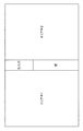
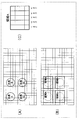
- FIG. 10 shows an example of a specific display of the display unit 157. As shown in FIG.
- the display in FIG. 10 indicates that it is "the third floor”.
- A-1, A-2, A-3, A-4, A-21, A-22, A-23 and A-24 respectively indicate the position of the parking space of the car.
- a-1 and a-2 indicate the position of the elevator.
- the map information including the parking space and the position of the elevator is an example of the desired information 454 (472).
- the display unit 157 maps and displays the current position of the terminal 450 on a map.
- the current position is information obtained from the information 156 including at least the location and position information of the terminal 450.
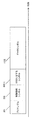
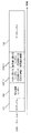
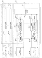
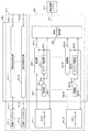
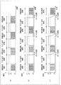
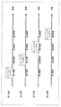
- FIG. 11 shows an example of a frame configuration of a modulated signal transmitted by the first device 400 shown in FIG.
- the horizontal axis is time.
- symbols that transmit the same information as in FIG. 7 are assigned the same reference numerals, and descriptions thereof will be omitted.
- the first device 400 transmits a symbol 600-1 related to the SSID and a symbol 600-2 related to the access destination, in addition to the preamble 201, the control information symbol 202, the symbol 203 related to location information or position information, and the symbol 204 related to time information.
- a symbol 600-1 related to the SSID is a symbol for transmitting information 401-1 related to the SSID in FIG. 9, and a symbol 600-2 related to the access destination is for transmitting information 401-2 related to the access destination in FIG. It is a symbol.
- symbols other than the symbols described in FIG. 11 may be included.
- the frame configuration, including the order of transmission of symbols, is not limited to the configuration of FIG.
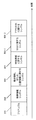
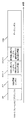
- FIG. 12 shows an example of a frame configuration of a modulated signal transmitted by the base station 470 shown in FIG. In FIG. 12, the horizontal axis is time.
- the base station 470 transmits, for example, a preamble 701 and then transmits a control information symbol 702 and an information symbol 703.
- the preamble 701 is a symbol for the terminal 450 that receives the modulated signal transmitted by the base station 470 to perform, for example, signal detection, time synchronization, frame synchronization, frequency synchronization, frequency offset estimation, and the like.
- the control information symbol 702 is, for example, a symbol including data such as an error correction coding scheme method, information on a modulation scheme, and information on a frame configuration, which is used to generate a modulation signal.
- the wireless device 453 of the terminal 450 demodulates the modulated signal based on the information of the control information symbol 702.
- An information symbol 703 is a symbol for transmitting information.
- the information symbol 703 is a symbol for transmitting the desired information 472 described above.
- Base station 470 shown in FIG. 9 may transmit a frame including symbols other than the symbols described in FIG. 12.
- the base station 470 may transmit a frame or the like including a pilot symbol (reference symbol) in the middle of the information symbol 703.
- the frame configuration, including the order of transmission of symbols is not limited to the configuration of FIG.
- a plurality of symbols may be present in the frequency axis direction. That is, in FIG. 12, symbols may exist in a plurality of frequencies (a plurality of carriers).
- a method of transmitting the modulation signal of the frame configuration shown in FIG. 11 transmitted by the first device 400 at regular timing may be considered.
- the plurality of terminals 450 can perform the operation as described above.
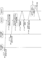
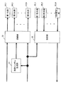
- FIG. 13 is a flowchart showing an example of the process performed by the “first device 400”, the “terminal 450” and the “base station 470” shown in FIG. 9 described above.
- the first device 400 transmits the modulation signal of the frame configuration shown in FIG. 11 (ST801).
- terminal 450 receives the modulated signal transmitted by first device 400, and performs location / position estimation of terminal 450 (ST 802).
- the terminal 450 receives the modulated signal transmitted by the first device 400 and recognizes the SSID of the base station 470 accessed by the terminal 450 (ST 803).
- terminal 450 transmits a modulation signal including data including information 452 on an access destination for obtaining information such as a map to base station 470 using a radio wave, for example (ST 804).
- Base station 470 receives the modulated signal transmitted by terminal 450, obtains access destination information, accesses a desired access destination via a network, and accesses desired information such as a map (information to be transmitted to terminal 450) ) Is obtained (ST 805).
- base station 470 transmits a modulated signal including the desired information such as the acquired map to terminal 450 using, for example, a radio wave (ST 806).
- Terminal 450 receives the modulated signal transmitted by base station 470 and obtains information such as a map. Then, the terminal 450 performs the display as shown in FIG. 10 based on the information such as the map and the information on the location and position of the terminal 450 which has already been obtained.
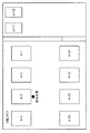
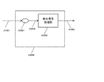
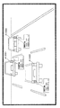
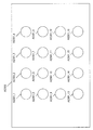
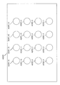
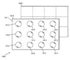
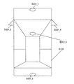
- FIG. 14 describes a map of the same place as FIG. That is, FIG. 14 is a map of “the third floor” as described in FIG. In FIG. 14, A-1, A-2, A-3, A-4, A-21, A-22, A-23 and A-24 indicate parking spaces of the car, and a-1, a- 2 shows an elevator.
- the first device 400 has information “A-1” as information on a place or information on a position, and transmits information “A-1”.
- the first device having the same configuration as the first device 400 of FIG. 9 is installed at the position of “o” 901-2 of FIG.
- the first device having the same configuration as the first device 400 installed at the position of 901-2 will be referred to as a “1-2th device 400”.
- the 1-2nd device 400 has the information “A-2” as the information on the place or the information on the position, and transmits the information “A-2”.
- the first device having the same configuration as the first device 400 of FIG. 9 is installed at the position of “o” 901-3 of FIG.
- the first device having the same configuration as the first device 400 installed at the position of 901-3 will be referred to as “1-3 of the device 400”.
- the first to third devices 400 have information “A-3” as information regarding a place or information regarding a position, and transmit information “A-3”.
- the first device having the same configuration as the first device 400 of FIG. 9 is installed at the position of “o” 901-4 of FIG.
- the first device having the same configuration as the first device 400 installed at the position 901-4 will be referred to as a “1-4th device 400”.
- the first to fourth devices 400 have information “A-4” as information regarding a place or information regarding a position, and transmit information “A-4”.
- the first device having the same configuration as the first device 400 of FIG. 9 is installed at the position of “o” 901-21 of FIG.
- the first device having the same configuration as that of the first device 400 installed at the position 901-21 will be referred to as a “1st-21st device 400”.
- the first device 21-1 has information “A-21” as information on a place or information on a position, and transmits information “A-21”.
- the first device having the same configuration as the first device 400 of FIG. 9 is installed at the position of “o” 901-22 of FIG.
- the first device having the same configuration as the first device 400 installed at the position of 901-22 will be referred to as a “1st-22 first device 400”.
- the device 1-22 has the information “A-22” as the information on the place or the information on the position, and transmits the information “A-22”.
- the first device having the same configuration as the first device 400 of FIG. 9 is installed at the position of “o” 901-23 of FIG.
- the first device having the same configuration as the first device 400 installed at the position of 901-23 will be referred to as “1-23 device 400”.
- the 1st to 23rd apparatus 400 has the information “A-23” as the information on the place or the information on the position, and transmits the information “A-23”.
- the first device having the same configuration as the first device 400 of FIG. 9 is installed at the position of “o” 901-24 of FIG.
- the first device having the same configuration as the first device 400 installed at the position 901-24 will be referred to as “1-24th device 400”.
- the device No. 1-24 has the information “A-24” as the information on the place or the information on the position, and transmits the information “A-24”.
- a base station (or AP) having a configuration similar to that of the base station 470 in FIG. 9 is installed at the position of “ ⁇ ” 902 in FIG.
- a base station (or AP) having a configuration similar to that of base station 470 in FIG. 9 will be simply referred to as “base station 470”.
- the SSID of the base station 470 installed at the position 902 is assumed to be “abcdef”.
- the terminal 450 present around the position shown in the map of FIG. 14 may access the base station 470 installed at the position of 902 of FIG. 14.
- the “1-1st device 400” installed in the 901-1 in FIG. 14 transmits “abcdef” as the information on the SSID (see 401-1 in FIG. 9).
- the “1-2nd device 400” installed in the 901-2 in FIG. 14 transmits “abcdef” as information related to the SSID (see 401-1 in FIG. 9).
- the “first to third device 400” installed in 901-3 of FIG. 14 transmits “abcdef” as information on the SSID (see 401-1 of FIG. 9).
- the “first to fourth device 400” installed in 901-4 in FIG. 14 transmits “abcdef” as information on the SSID (see 401-1 in FIG. 9).
- the “1st device 21-1” installed in 901-21 of FIG. 14 transmits “abcdef” as information on the SSID (see 401-1 in FIG. 9).
- the “1st-2nd device 400” installed in 901-22 in FIG. 14 transmits “abcdef” as information on the SSID (see 401-1 in FIG. 9).
- the “1-23 device 400” installed in 901-23 of FIG. 14 transmits “abcdef” as information related to the SSID (see 401-1 of FIG. 9).
- the “1-24 device 400” installed in 901-24 of FIG. 14 transmits “abcdef” as information related to the SSID (see 401-1 of FIG. 9).
- terminal 450 a terminal having a configuration similar to that of the terminal 450 of FIG. 9 (hereinafter simply referred to as “terminal 450”) exists at the position 903-1 of FIG.
- the terminal 450 receives the modulated signal transmitted by the “first to fourth device 400” at the position 901-4 in FIG. 14, and obtains position information “A-4”.
- the terminal 450 receives the modulated signal transmitted by the “first to fourth device 400” at the position 901-4 in FIG. 14, and obtains information on the SSID “abcdef”. This will cause terminal 450 to access base station 470 located at 902 in FIG.
- the terminal 450 obtains information such as a map from the base station 470 located at 902 in FIG.
- the terminal 450 displays map information and position information (see, for example, FIG. 10, but FIG. 10 is merely an example of display).
- terminal 450 a terminal having a configuration similar to that of the terminal 450 of FIG. 9 (hereinafter simply referred to as “terminal 450”) exists at the position of 903-2 in FIG.
- the terminal 450 receives the modulated signal transmitted by the “first 22 device 400” at the position 901-22 in FIG. 14, and obtains position information “A-22”.
- the terminal 450 receives the modulated signal transmitted by the “first to fourth device 400” at the position 901-22 in FIG. 14, and obtains information of the SSID “abcdef”. This will cause terminal 450 to access base station 470 located at 902 in FIG.
- the terminal 450 obtains information such as a map from the base station 470 located at 902 in FIG.
- the terminal 450 displays map information and position information (see, for example, FIG. 10, but FIG. 10 is merely an example of display).
- Terminal 450 records a map (peripheral information) as shown in FIG. 14 and position information in a storage unit (not shown) of terminal 450, and stores it when a user who uses terminal 450 is required. The information recorded in the unit may be taken out. This allows the user to more conveniently utilize the map (peripheral information) and the position information.
- the terminal 450 that can receive this modulation signal can receive the optical signal from the position of the first device 400. It is limited within the range. Therefore, when the terminal 450 receives the location / position information transmitted by the first device 400, the terminal 450 can easily acquire high-accuracy position information (without performing complicated signal processing).
- the terminal 450 transmits the modulated signal that the first device 400 transmits even in a situation where radio waves from GPS satellites are difficult to receive. By receiving it, highly accurate position information can be obtained safely.
- the terminal 450 connects with the base station (or AP) 470 to obtain the information, and the terminal 450 acquires the information safely. be able to.
- the terminal 450 obtains information from the modulation signal of visible light
- the user can easily recognize the first device 400 that has transmitted the modulation signal by visual inspection or the like because it is visible light, and the information source It is because it is easy to judge whether it is safe.
- the SSID is acquired from a modulated signal of radio waves transmitted by the wireless LAN, it is difficult for the user to determine the device which transmitted the radio waves. For this reason, in terms of securing the security of information, visible light communication is suitable for acquiring an SSID as compared with wireless LAN communication.
- a plurality of signals may be further input to the wireless device 453 of the terminal 450 of FIG. 9.
- a control signal for controlling the wireless device 453 and information to be transmitted to the base station 470 may be input to the wireless device 453.
- an operation in which the wireless device 453 starts communication based on the control signal is considered as an example.
- the configuration of the first device is not limited to the configuration of the first device 400 of FIG. 9, and the configuration of the terminal is limited to the configuration of the terminal 450 of FIG.
- the connection destination and configuration of the base station are not limited to the connection destination and configuration of the base station 470 shown in FIG.
- FIG. 9 describes the case where one base station 470 is arranged, there may be a plurality of (secure) base stations (or APs) accessible by the terminal 450.
- the symbol related to the SSID transmitted by the first device 400 in FIG. 9 may include information indicating the SSID of each of the plurality of base stations (or APs).
- the display unit 157 of the terminal 450 of FIG. 9 displays a list of SSIDs of a plurality of base stations and / or a list of a plurality of access destinations as a display of the access destination (the above-mentioned “first display”). Is displayed.
- the terminal 450 of FIG. 9 may select one or more base stations to which a wireless connection is actually made based on the information of the SSIDs of a plurality of base stations (or APs) (that is, a plurality of base stations). You may connect at the same time).
- the three base stations 470 are arranged.
- the three base stations 470 are referred to as a base station #A, a base station #B, and a base station #C, respectively.
- the SSID of the base station #A is "abcdef”
- the SSID of the base station #B is "ghijk”
- the SSID of the base station #C is "pqrstu”.
- the terminal 450 in FIG. 9 receives the symbol 600-1 relating to the SSID, “an SSID of base station #A is“ abcdef ”,“ an SSID of base station #B is “ghijk”, “base station #C”.
- the one or more base stations 470 to which the wireless connection is actually made are selected based on the information of the “pqrstu” of the SSID of “1”.
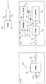
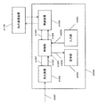
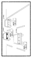
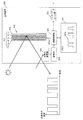
- FIG. 15 is a diagram showing an example of a configuration of a communication system in the present embodiment.
- the communication system in FIG. 15 includes, for example, a device 1000, a terminal 1050, and a base station (or AP) 470 that communicates with the terminal 1050.
- the device 1000 includes, for example, a visible light source such as an LED, an illumination, a light source, and a light (hereinafter, referred to as a light source 104).
- a visible light source such as an LED
- an illumination such as a light source
- a light source 104 a light
- the device 1000 may be referred to as a “second device” in the present embodiment.
- the components operating in the same manner as the first device 100 shown in FIG. Further, in the terminal 1050 shown in FIG. 15, the same elements as those of the terminal 150 shown in FIG. Further, communication between the wireless device 453 of the terminal 1050 and the base station 470 shown in FIG. 15 uses radio waves, for example.
- the transmitting unit 102 receives the information 1001-1 related to the SSID, the information 1001-2 related to the encryption key, and the data 1002 as input, and (light) modulation is performed based on these input signals.
- a signal 103 is generated and a modulation signal 103 is output. Then, the modulation signal 103 is transmitted from, for example, the light source 104.
- the information 1001-1 related to the SSID is information indicating the SSID of the base station 470 in FIG.
- base station 470 transmits the modulated signal to terminal 1050 by radio wave, and receives the modulated signal from terminal 1050 by radio wave. That is, the second device 1000 can provide the terminal 1050 with access to the base station 470, which is a safe access destination. This allows terminal 1050 in FIG. 15 to obtain information securely from base station 470.
- the second device 1000 can limit terminals accessing the base station 470 to terminals located in a space where the optical signal transmitted (irradiated) by the second device 1000 can be received.
- the terminal 1050 may determine that the notified SSID is the SSID of a secure base station. Also, the terminal 1050 may separately perform a process of determining whether the notified SSID is secure. For example, the second device 1000 transmits a predetermined identifier included in an optical signal, and the terminal 1050 determines whether the notified SSID is the SSID of a secure base station based on the received identifier. May be
- the terminal 1050 obtains the SSID acquired from the second device 1000. It will be used to access the base station 470 to obtain information.
- the information 1001-2 related to the encryption key is information related to the encryption key required for the terminal 1050 to communicate with the base station 470.
- the terminal 1050 can perform encrypted communication with the base station 470 by obtaining the information 1001-2 related to the encryption key from the second device 1000.
- the terminal 1050 in FIG. 15 receives the modulated signal transmitted by the second device 1000.
- the same components as those of the terminal 150 of FIG. 6 and the terminal 450 of FIG. 9 are denoted by the same reference numerals.
- the light receiving unit 151 included in the terminal 1050 is, for example, an image sensor such as a CMOS or an organic CMOS.
- the light receiving unit 151 receives light including the modulation signal transmitted from the second device 1000, and outputs a reception signal 152.
- the receiving unit 153 receives the received signal 152 received by the light receiving unit 151 as input, performs processing such as demodulation and error correction decoding on the modulation signal included in the received signal 152, and outputs received data 154.
- the data analysis unit 155 receives the received data 154, and from the received data 154, for example, information 1051 of the SSID of the base station to be connected and information of an encryption key for communicating with the base station to be connected.
- Output 1052 For example, in a wireless LAN (Local Area Network), WEP (Wired Equivalent Privacy), WPA (Wi-Fi Protected Access), WPA2 (Wi-Fi Protected Access 2) (PSK (Pre-Shared Key)) may be used as an encryption method. There is a mode, EAP (Extended Authentication Protocol) mode). Note that the encryption method is not limited to this.
- the display unit 157 receives the information 1051 of the SSID and the information 1052 of the encryption key, and displays, for example, the SSID of the communication counterpart accessed by the wireless device 453 of the terminal 1050 and the encryption key (this display is performed Called “the first display” in the form of
- the wireless device 453 receives the information 1051 of the SSID and the information 1052 of the encryption key, and establishes a connection with the base station 470 (for example, the connection uses a radio wave).
- the base station 470 transmits the modulation signal using, for example, a radio wave.
- the wireless device 453 receives the data 1053 and the control signal 1054, modulates the data 1053 according to the control indicated by the control signal 1054, and transmits the modulated signal by radio wave.
- the base station 470 transmits data to the network (471) and receives data from the network (472). Thereafter, for example, base station 470 transmits the modulated signal to terminal 1050 by radio wave.
- the wireless device 453 included in the terminal 1050 performs processing such as demodulation and error correction decoding on the modulated signal received by radio waves, and acquires received data 1056.
- the display unit 157 performs display based on the received data 1056.
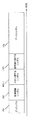
- FIG. 16 shows an example of a frame configuration of a modulated signal transmitted by the second device 1000 shown in FIG.
- the horizontal axis is time.
- the same symbols as in FIG. 7 and FIG. 11 carry the same reference numerals, and the explanation thereof is omitted.
- a symbol 600-1 related to the SSID is a symbol for transmitting the information 1001-1 related to the SSID in FIG. 15, and a symbol 1101 related to the encryption key is a symbol for transmitting the information 1001-2 related to the encryption key in FIG. is there.
- the data symbol 1102 is a symbol for transmitting the data 1002 of FIG.
- the second device 1000 transmits a preamble 201, a control information symbol 202, a symbol 600-1 related to an SSID, a symbol 1101 related to an encryption key, and a data symbol 1102.
- the second device 1000 may transmit a frame including symbols other than the symbols described in FIG. Also, the frame configuration is not limited to the configuration of FIG. 16 including the order of transmitting symbols.
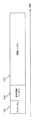
- FIG. 17 illustrates an example of a frame configuration of a modulated signal transmitted by the wireless device 453 included in the terminal 1050 in FIG.
- the horizontal axis is time.
- the wireless device 453 included in the terminal 1050 transmits a preamble 1201 and then transmits a control information symbol 1202 and an information symbol 1203.
- the preamble 1201 is a symbol used by the base station 470 that receives a modulated signal transmitted by the wireless device 453 of the terminal 1050, for example, to perform signal detection, time synchronization, frame synchronization, frequency synchronization, frequency offset estimation, and the like.
- the control information symbol 1202 is, for example, a symbol including data such as an error correction coding method used to generate a modulation signal, information on a modulation method, information on a frame configuration, and information on a transmission method.
- Base station 470 demodulates the modulated signal based on the information included in control information symbol 1202.
- the information symbol 1203 is a symbol for the wireless device 453 of the terminal 1050 to transmit data.
- the wireless device 453 of the terminal 1050 may transmit a frame including symbols other than the symbols described in FIG.
- the wireless device 453 may transmit a frame including a pilot symbol (reference symbol) in the middle of the information symbol 1203.
- the frame configuration, including the order of transmitting symbols is not limited to the configuration of FIG.
- a plurality of symbols may be present in the frequency axis direction. That is, in FIG. 17, symbols may exist in a plurality of frequencies (a plurality of carriers).
- the frame configuration of FIG. 17 may be used.
- the frame configuration of the modulated signal transmitted by base station 470 in the present embodiment is the same as the frame configuration of FIG. 12 described in the third embodiment. That is, as shown in FIG. 12, the base station 470 transmits, for example, a preamble 701, and then transmits a control information symbol 702 and an information symbol 703.
- the preamble 701 is a symbol for the wireless device 453 of the terminal 1050 that receives the modulated signal transmitted by the base station 470 to perform, for example, signal detection, time synchronization, frame synchronization, frequency synchronization, frequency offset estimation and the like.
- the control information symbol 702 is, for example, a symbol including data such as an error correction coding method, information on a modulation method, information on a frame configuration, and information on a transmission method, which is used to generate a modulation signal.
- the wireless device 453 of the terminal 1050 demodulates the modulated signal based on the information of the control information symbol 702.
- the information symbol 703 is a symbol for the base station 470 to transmit data.
- Base station 470 shown in FIG. 15 may transmit a frame including symbols other than the symbols described in FIG.
- the base station 470 may transmit a frame or the like including a pilot symbol (reference symbol) in the middle of the information symbol 703.
- the frame configuration, including the order of transmitting symbols is not limited to the configuration of FIG.
- a plurality of symbols may be present in the frequency axis direction. That is, in FIG. 12, symbols may exist in a plurality of frequencies (a plurality of carriers).
- a method may be considered in which the modulation signal of the frame configuration in FIG. 16 transmitted by the second device 1000 is repeatedly transmitted, for example, at regular timing. Thereby, the plurality of terminals 1050 can perform the operation as described above.
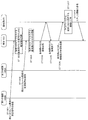
- FIG. 18 is a flowchart illustrating an example of processing performed by the “second device 1000”, the “terminal 1050”, and the “base station 470” illustrated in FIG.
- the second device 1000 transmits the modulation signal of the frame configuration shown in FIG. 16 (ST1301).
- the terminal 1050 receives the modulated signal transmitted by the second device 1000, and acquires the SSID of the base station 470 accessed by the terminal 1050 (ST1302).
- the terminal 1050 acquires an encryption key used for communication with the base station 470 accessed by the terminal 1050 (ST1303).
- terminal 1050 performs connection with base station 470 by radio waves (ST1304).
- terminal 1050 receives the response of the base station 470, the connection with the base station 470 is completed (ST1305).
- terminal 1050 transmits connection destination information to base station 470 using a radio wave (ST1306).
- Base station 470 obtains information for transmission to terminal 1050 from the network (ST 1307).
- base station 470 transmits the obtained information to terminal 1050 using radio waves, and terminal 1050 obtains information (ST1308).
- Terminal 1050 may, for example, obtain necessary information from the network via base station 470 when necessary.
- the terminal 1050 is connected to the base station 470 based on the information on the SSID and the information on the encryption key transmitted from the second device 1000, and security is guaranteed by acquiring the information.
- Information can be obtained securely through base station 470. This is because when the terminal 1050 obtains information from a modulation signal of visible light, the user can easily determine whether the information source is safe because the light is visible light.
- the SSID is acquired from a modulated signal of radio waves transmitted by the wireless LAN, it is difficult for the user to determine the device which transmitted the radio waves. For this reason, in terms of securing the security of information, visible light communication is suitable for acquiring an SSID as compared with wireless LAN communication.
- the second device 1000 transmits the information of the encryption key.
- the second device 1000 may transmit only the information on the SSID without transmitting the information on the encryption key. .
- the configuration of the second device is not limited to the configuration of the second device 1000 shown in FIG. 15, and the configuration of the terminal is not limited to the configuration of the terminal 1050 shown in FIG.
- the destination and the configuration are not limited to the connection destination and configuration of the base station 470 shown in FIG.
- FIG. 15 describes the case where one base station 470 is arranged, a plurality of (secure) base stations (or APs) accessible by the terminal 1050 may exist.
- the plurality of base stations and the terminal 1050 transmit and receive modulated signals using radio waves.
- the symbol related to the SSID transmitted by the second device 1000 in FIG. 15 may include information on the respective SSIDs of the plurality of base stations (or APs).
- the display unit 157 of the terminal 1050 in FIG. 15 displays a list of SSIDs of a plurality of base stations and / or a list of a plurality of access destinations as a display of access destinations.
- the terminal 1050 in FIG. 15 may include information on the encryption key used to connect to each of the plurality of base stations (or APs). . Then, the terminal 1050 in FIG. 15 may select one or more base stations to be actually wirelessly connected (for example, by radio waves) based on the information on the SSIDs of the plurality of base stations and the information on the encryption key ( That is, multiple base stations may be connected simultaneously).
- the three base stations 470 are arranged.
- the three base stations 470 are referred to as a base station #A, a base station #B, and a base station #C, respectively.
- the SSID of the base station #A is "abcdef”
- the SSID of the base station #B is "ghijk”
- the SSID of the base station #C is "pqrstu”.
- the encryption key for connecting to the base station #A is "123”
- the encryption key for connecting to the base station #B is "456”
- the encryption key for connecting to the base station #C is "789".
- the symbol 600-1 related to the SSID in the frame configuration in FIG. 16 of the modulated signal transmitted by the second device 1000 is "Abcdef for SSID of base station #A," “SSID for base station #B.” "Ghijk” and “pqrstu” are included as information on the SSID of the base station #C.
- the symbol 1101 related to the encryption key in the frame configuration in FIG. 16 is "the encryption key for connecting to the base station #A is” 123 ", and” the encryption key for connecting to the base station #B is "456".
- “The encryption key for connecting to the base station #C is“ 789 ””.
- the terminal 1050 in FIG. 15 receives the symbol 600-1 relating to the SSID, and “the SSID of the base station #A is“ abcdef ”,“ the SSID of the base station #B is “ghijk”, “the base station #C Get information of "pqrstu” for the SSID. Also, the terminal 1050 receives the symbol 1101 related to the encryption key, and “the encryption key for connecting to the base station #A is“ 123 ”, and“ the encryption key for connecting to the base station #B is “456” ”. "The encryption key for connecting to the base station #C is" 789 "to obtain information. Then, the terminal 1050 selects and connects one or more base stations to be actually wirelessly connected (for example, by radio waves) based on these pieces of information.
- the present embodiment by setting base station 470 accessed by terminal 1050 using a light source such as an LED as an example, it is possible to use terminal 1050 as a modulation signal for radio transmission by terminal 1050. There is no need for a special setting mode for performing a procedure for wireless communication connection with the base station 470. Also, the modulation signal transmitted by the base station 470 does not require a special setting mode for performing a procedure for connection of wireless communication between the terminal 1050 and the base station 470. Thus, in the present embodiment, the data transmission efficiency of wireless communication can be improved.
- the encryption key may be an encryption key for the SSID of the wireless LAN, or may be an encryption key for limiting the connection mode, the service mode, the connection range of the network, and the like. That is, an encryption key may be introduced for some restriction.
- FIG. 19 is a diagram showing an example of a configuration of a communication system in the present embodiment.
- the communication system in FIG. 19 includes, for example, devices 1400A and 1400B, a terminal 1050, and a base station (or AP) 470 that communicates with the terminal 1050.
- the devices 1400A and 1400B include, for example, visible light sources such as LEDs, illuminations, light sources, and lights (hereinafter referred to as light sources 1406-1 and 1406-2).
- the device 1400A will be referred to as the "third device” in the present embodiment, and the device 1400B will be referred to as the "fourth device” in the present embodiment.
- the transmission unit 1404-1 receives the information 1401-1 and data 1402-1 related to the SSID, and generates the (light) modulation signal 1405-1 based on these input signals. And output the modulation signal 1405-1. Then, the modulation signal 1405-1 is transmitted from, for example, the light source 1406-1.
- the transmitting unit 1404-2 receives the information 1403-2 concerning the encryption key and the data 1402-2, and based on these input signals, the (optical) modulation signal 1405-2 is It generates and outputs a modulation signal 1405-2. Then, the modulation signal 1405-2 is transmitted from, for example, the light source 1406-2.
- the information 1401-1 related to the SSID is information indicating the SSID of the base station 470 in FIG. That is, the third device 1400A can provide the terminal 1050 with access to the base station 470, which is a safe access destination by radio waves. This allows terminal 1050 in FIG. 19 to obtain information securely from base station 470.
- the terminal 1050 may determine that the notified SSID is the SSID of a secure base station. Also, the terminal 1050 may separately perform a process of determining whether the notified SSID is secure. For example, the third device 1400A includes a predetermined identifier in the optical signal and transmits it, and the terminal 1050 determines whether the notified SSID is the SSID of a secure base station based on the received identifier. May be
- the terminal 1050 obtains the SSID and the information acquired from the third device 1400A.
- Information is acquired by accessing the base station 470 using the encryption key acquired from the fourth device 1400B.
- the information 1403-2 related to the encryption key is information related to the encryption key required for the terminal 1050 to communicate with the base station 470 by radio waves.
- the terminal 1050 can perform encrypted communication with the base station 470 by obtaining the information 1403-2 related to the encryption key from the fourth device 1400B.
- the information 1401-1 related to the SSID and the information 1403-2 related to the encryption key have been described above.
- the terminal 1050 in FIG. 19 receives the modulated signal transmitted by the third device 1400A.
- the light receiving unit 151 included in the terminal 1050 is, for example, an image sensor such as a CMOS or an organic CMOS.
- the light receiving unit 151 receives light including the modulation signal transmitted from the third device 1400A, and outputs a reception signal 152.
- the receiving unit 153 receives the received signal 152 received by the light receiving unit 151 as input, performs processing such as demodulation and error correction decoding on the modulation signal included in the received signal 152, and outputs received data 154.
- the data analysis unit 155 receives the received data 154, and outputs, for example, information 1051 of the SSID of a base station to be a connection destination from the received data.
- the wireless device 453 obtains the information of the SSID of the base station 470 to which the wireless device 453 is connected by radio waves from the information 1051 of the SSID.
- the terminal 1050 in FIG. 19 receives the modulated signal transmitted by the fourth device 1400B.
- the light receiving unit 151 of the terminal 1050 is, for example, an image sensor such as a CMOS or an organic CMOS.
- the light receiving unit 151 receives light including the modulation signal transmitted from the fourth device 1400 B, and outputs a reception signal 152.
- the receiving unit 153 receives the received signal 152 received by the light receiving unit 151 as input, performs processing such as demodulation and error correction decoding on the modulation signal included in the received signal 152, and outputs received data 154.
- the data analysis unit 155 receives the received data 154 and outputs, from the received data, for example, information 1052 of an encryption key for communicating with a base station to be a connection destination.
- information 1052 of an encryption key for communicating with a base station to be a connection destination.
- WEP Wi-Fi Protected Access
- WPA2 Wi-Fi Protected Access 2
- PSK Pre-Shared Key
- EAP Extended Authentication Protocol
- the wireless device 453 included in the terminal 1050 is the information on the encryption key of the base station 470 to which the wireless device 453 is connected, from the information 1052 on the encryption key for communicating with the base station to which the connection is made I will get it.
- the display unit 157 receives the information 1051 of the SSID and the information 1052 of the encryption key, and displays, for example, the SSID of the communication counterpart accessed by the wireless device 453 of the terminal 1050 and the encryption key (this display is performed Called “the first display” in the form of
- the wireless device 453 receives the information 1051 of the SSID and the information 1052 of the encryption key, and establishes a radio wave connection with the base station 470.
- the base station 470 transmits the modulation signal using, for example, a radio wave.
- the wireless device 453 receives the data 1053 and the control signal 1054, modulates the data 1053 according to the control indicated by the control signal 1054, and transmits the modulated signal by radio wave.
- the base station 470 transmits data to the network (471) and receives data from the network (472). Thereafter, for example, base station 470 transmits the modulated signal to terminal 1050 by radio wave.
- the wireless device 453 included in the terminal 1050 performs processing such as demodulation and error correction decoding on the modulated signal received by radio waves, and acquires received data 1056.
- the display unit 157 performs display based on the received data 1056.
- FIG. 20 shows an example of a frame configuration of a modulated signal transmitted by the third device 1400A shown in FIG.
- the horizontal axis is time. Further, in FIG. 20, the same symbols as in FIG. 2, FIG. 11, and FIG.
- the symbol 600-1 related to the SSID is a symbol for transmitting the information 1401-1 related to the SSID in FIG.
- Data symbol 1102 is a symbol for transmitting data 1402-1.
- the third device 1400A transmits a preamble 201, a control information symbol 202, a symbol 600-1 related to an SSID, and a data symbol 1102.
- the third device 1400A may transmit a frame including symbols other than the symbols described in FIG. Also, the frame configuration, including the order of transmitting symbols, is not limited to the configuration of FIG.
- FIG. 21 shows an example of a frame configuration of a modulated signal transmitted by the fourth device 1400B of FIG.
- the horizontal axis is time. Further, in FIG. 21, the same symbols as in FIG. 7 and FIG.
- the symbol 1101 related to the encryption key is a symbol for transmitting the information 1403-2 related to the encryption key in FIG.
- Data symbol 1102 is a symbol for transmitting data 1402-2.
- the fourth device 1400 B transmits a preamble 201, a control information symbol 202, a symbol 1101 related to an encryption key, and a data symbol 1102.
- the fourth device 1400B of FIG. 19 may transmit a frame including symbols other than the symbols described in FIG. Also, the frame configuration including the order of transmitting symbols is not limited to that shown in FIG.
- the frame configuration of the modulated signal transmitted by the wireless device 453 in the present embodiment is the same as the frame configuration of FIG. 17 described in the fourth embodiment. That is, as shown in FIG. 17, the wireless device 453 included in the terminal 1050 transmits, for example, a preamble 1201 and then transmits a control information symbol 1202 and an information symbol 1203.
- the preamble 1201 is, for example, signal detection, time synchronization, frame synchronization, frequency synchronization, frequency offset estimation, etc. by the base station (or AP) 470 that receives the modulated signal transmitted by the wireless device 453 of the terminal 1050 in FIG. It is a symbol used to do it.
- the control information symbol 1202 is, for example, a symbol including data such as an error correction coding method, information on a modulation method, information on a frame configuration, and information on a transmission method, which is used to generate a modulation signal.
- Base station 470 demodulates the modulated signal based on the information included in control information symbol 1202.
- the information symbol 1203 is a symbol for the wireless device 453 of the terminal 1050 to transmit data.
- the wireless device 453 of the terminal 1050 shown in FIG. 19 may transmit a frame including symbols other than the symbols described in FIG.
- the wireless device 453 may transmit a frame or the like including a pilot symbol (reference symbol) in the middle of the information symbol 1203.
- the frame configuration, including the order of transmitting symbols is not limited to the configuration of FIG.
- a plurality of symbols may be present in the frequency axis direction. That is, in FIG. 17, symbols may exist in a plurality of frequencies (a plurality of carriers).
- the frame configuration of the modulated signal transmitted by base station 470 in the present embodiment is the same as the frame configuration of FIG. 12 described in the third embodiment. That is, as shown in FIG. 12, the base station 470 transmits, for example, a preamble 701, and then transmits a control information symbol 702 and an information symbol 703.
- the preamble 701 is a symbol for the wireless device 453 of the terminal 1050 in FIG. 19 that receives the modulated signal transmitted by the base station 470 to perform, for example, signal detection, time synchronization, frame synchronization, frequency synchronization, frequency offset estimation, etc. is there.
- the control information symbol 702 is, for example, a symbol including data such as an error correction coding method, information on a modulation method, information on a frame configuration, and information on a transmission method, which is used to generate a modulation signal.
- the wireless device 453 of the terminal 1050 in FIG. 19 performs demodulation of the modulated signal based on the information of the control information symbol 702.
- An information symbol 703 is a symbol for the base station 470 in FIG. 19 to transmit data.
- Base station 470 shown in FIG. 19 may transmit a frame including symbols other than the symbols described in FIG.
- the base station 470 may transmit a frame or the like including a pilot symbol (reference symbol) in the middle of the information symbol 703.
- the frame configuration, including the order of transmitting symbols is not limited to the configuration of FIG.
- a plurality of symbols may be present in the frequency axis direction. That is, in FIG. 12, symbols may exist in a plurality of frequencies (a plurality of carriers).
- a method may be considered in which the modulation signal of the frame configuration in FIG. 20 transmitted by the third device 1400A is repeatedly transmitted, for example, at regular timing. Thereby, the plurality of terminals 1050 can perform the operation as described above.
- the modulation signal of the frame configuration in FIG. 21 transmitted by the fourth device 1400B may be repeatedly transmitted, for example, at regular timing. Thereby, the plurality of terminals 1050 can perform the operation as described above.
- FIG. 22 is a flowchart showing a first example of processing performed by the “third device 1400A”, the “fourth device 1400B”, the “terminal 1050”, and the “base station 470” shown in FIG.
- the same reference numerals are given to those that operate in the same manner as in FIG.
- the third apparatus 1400A transmits a modulated signal having a frame configuration shown in FIG. 20 (ST1701).
- the terminal 1050 receives the modulated signal transmitted by the third device 1400A, and acquires the SSID of the base station 470 accessed by the terminal 1050 (ST1702).
- the fourth device 1400B transmits the modulation signal of the frame configuration shown in FIG. 21 (ST1703).
- the terminal 1050 receives the modulated signal transmitted by the fourth device 1400 B, and acquires an encryption key used for communication with the base station 470 accessed by the terminal 1050 (ST 1704).
- terminal 1050 performs connection with base station 470 by radio waves (ST1304).
- terminal 1050 receives the response of the base station 470, the connection with the base station 470 by radio waves is completed (ST1305).
- terminal 1050 transmits connection destination information to base station 470 using a radio wave (ST1306).
- Base station 470 obtains information for transmission to terminal 1050 from the network (ST 1307).
- base station 470 transmits the obtained information to terminal 1050 using radio waves, and terminal 1050 obtains information (ST1308).
- Terminal 1050 may, for example, obtain necessary information from the network via base station 470 when necessary.
- FIG. 23 is a flowchart showing a second example of the process performed by the “third device 1400A”, the “fourth device 1400B”, the “terminal 1050”, and the “base station 470” shown in FIG. Note that, in FIG. 23, the same operation as in FIG. 18 is denoted by the same reference numeral.
- the fourth device 1400B transmits the modulation signal of the frame configuration shown in FIG. 21 (ST1801).
- terminal 1050 receives the modulated signal transmitted by fourth device 1400 B, and acquires an encryption key used for communication with base station 470 accessed by terminal 1050 (ST 1802).
- the third device 1400A transmits the modulation signal of the frame configuration shown in FIG. 20 (ST1803).
- the terminal 1050 receives the modulated signal transmitted by the third device 1400A, and acquires the SSID of the base station 470 accessed by the terminal 1050 (ST1804).
- terminal 1050 performs connection with base station 470 by radio waves (ST1304).
- terminal 1050 receives the response of the base station 470, the connection with the base station 470 by radio waves is completed (ST1305).
- terminal 1050 transmits connection destination information to base station 470 using a radio wave (ST1306).
- Base station 470 obtains information for transmission to terminal 1050 from the network (ST 1307).
- base station 470 transmits the obtained information to terminal 1050 using radio waves, and terminal 1050 obtains information (ST1308).
- Terminal 1050 may, for example, obtain necessary information from the network via base station 470 when necessary.
- the terminal 1050 connects to the base station 470 and acquires information. . That is, since the device from which the terminal 1050 acquires information on the SSID is different from the device from which the information on the encryption key is acquired, the information can be acquired safely via the base station 470 with guaranteed security. This is because when the terminal 1050 obtains information from a modulation signal of visible light, the user can easily determine whether the information source is safe because the light is visible light. On the other hand, for example, when the SSID is acquired from a modulated signal of radio waves transmitted by the wireless LAN, it is difficult for the user to determine the device which transmitted the radio waves. For this reason, in terms of securing the security of information, visible light communication is suitable for acquiring an SSID as compared with wireless LAN communication.
- the fourth device 1400B transmits the information of the encryption key.
- the information of the encryption key is not transmitted by the fourth device 1400B, and only the information related to the SSID is transmitted by the third device 1400A. It may be sent. In this case, it is possible to implement similarly, only by deleting the configuration related to the encryption key in the above-described lower configuration.
- the terminal 1050 is configured by separately setting the device (third device 1400A) that transmits information related to the SSID and the device (fourth device 1400B) that transmits information related to the encryption key. Can realize more secure communication with the base station 470.
- FIG. 24 For example, consider a space as shown in FIG. In FIG. 24, there are an area # 1 and an area # 2, and there is an entrance and a wall between the area # 1 and the area # 2. That is, in the space of FIG. 24, the movement of the area # 1 to the area # 2 and the movement of the area # 2 to the area # 1 can be performed only from the entrance.
- the base station 470, the third device 1400A, and the fourth device 1400B are installed in the area # 1 of FIG.
- radio waves transmitted by the base station 470 can be received in any of the area # 1 and the area # 2.
- the terminal 1050 present in the area # 1 in which the fourth device 1400B is installed acquires the encryption key of the base station 470 from the fourth device 1400B, and can communicate with the base station 470. Also, even when the terminal 1050 connected to the base station 470 in the area # 1 moves to the area # 2, the base using the encryption key acquired from the fourth device 1400B in the area # 1 Communication with station 470 is possible. Also, the terminal 1050 connected to the base station 470 in area # 1 moves to an area other than area # 1 or area # 2, and then returns to one of area # 1 or area # 2 Also in this case, communication with the base station 470 is possible using the encryption key acquired from the fourth device 1400B in the area # 1.
- the terminal 1050 which can not enter the area # 1 can not obtain the encryption key from the fourth device 1400B.
- the terminal 1050 knows only the SSID of the base station (or AP) 470. Therefore, for example, the terminal 1050 may be able to receive communication with the base station 470 by a service that can be enjoyed by knowing only the SSID of the base station 470.
- the services that can be enjoyed by knowing only the SSID of the base station 470 can be more limited than the services that can be enjoyed when both the SSID and the encryption key are known.
- the terminal 1050 holding the encryption key before the change communicates with the base station 470 by changing the encryption key for the terminal 1050 to communicate with the base station 470 (for example, every certain time interval) It will not be possible. By performing such an operation, more secure communication can be performed.
- the configuration of the third device and the configuration of the fourth device are not limited to the configurations of the third device 1400A and the fourth device 1400B shown in FIG. 19, and the terminal configuration is the terminal shown in FIG.
- the connection destination and configuration of the base station are not limited to those of 1050, and the connection destination and configuration of the base station 470 shown in FIG. 19 are not limited to those.
- FIG. 19 describes the case where one base station 470 is arranged, there may be a plurality of (secure) base stations (or APs) accessible by the terminal 1050.
- the symbol related to the SSID transmitted by the third device 1400A in FIG. 19 may include information on the SSID of each of the plurality of base stations 470.
- the symbol related to the encryption key transmitted by the fourth device 1400B of FIG. 19 may include information of the encryption key used to connect to each of the plurality of base stations.
- the terminal 1050 in FIG. 19 may select one or more base stations to which a wireless connection is actually made based on the information on the SSIDs of the plurality of base stations and the information on the encryption key (that is, a plurality of base stations You may connect at the same time).
- the three base stations 470 are arranged.
- the three base stations 470 are referred to as a base station #A, a base station #B, and a base station #C, respectively.
- the SSID of the base station #A is "abcdef”
- the SSID of the base station #B is "ghijk”
- the SSID of the base station #C is "pqrstu”.
- the encryption key for connecting to the base station #A is "123”
- the encryption key for connecting to the base station #B is "456”
- the encryption key for connecting to the base station #C is "789".
- the symbol 600-1 related to the SSID in the frame configuration of FIG. 20 of the modulated signal transmitted by the third device 1400A is "Abcdef for the SSID of the base station #A," "SSID for the base station #B.” "Ghijk” and “pqrstu” are included as information on the SSID of the base station #C.
- the symbol 1101 related to the encryption key in the frame configuration of FIG. 21 of the modulated signal transmitted by the fourth device 1400B corresponds to “the encryption key for connecting to the base station #A“ 123 ”” and “base station #B and It includes information in which the encryption key for connection is “456”, and the encryption key for connection to the base station #C is “789”.
- the terminal 1050 in FIG. 19 receives the symbol 600-1 relating to the SSID, and “the SSID of the base station #A is“ abcdef ”,“ the SSID of the base station #B is “ghijk”, “the base station #C Get information of "pqrstu” for the SSID. Also, the terminal 1050 receives the symbol 1101 related to the encryption key, and “the encryption key for connecting to the base station #A is“ 123 ”, and“ the encryption key for connecting to the base station #B is “456” ”. "The encryption key for connecting to the base station #C is" 789 "to obtain information. Then, the terminal 1050 selects and connects a base station to be connected wirelessly (for example, by radio waves) based on the information.
- the present embodiment by setting base station 470 accessed by terminal 1050 using a light source such as an LED as an example, it is possible to use terminal 1050 as a modulation signal for radio transmission by terminal 1050. There is no need for a special setting mode for performing a procedure for wireless communication connection with the base station 470. Also, the modulation signal transmitted by the base station 470 does not require a special setting mode for performing a procedure for connection of wireless communication between the terminal 1050 and the base station 470. Thus, in the present embodiment, the data transmission efficiency of wireless communication can be improved.
- the encryption key may be an encryption key for the SSID of the wireless LAN, or may be an encryption key for limiting the connection mode, the service mode, the connection range of the network, and the like. That is, an encryption key may be introduced for some restriction.
- FIG. 25 is a diagram showing an example of a configuration of a communication system in the present embodiment.
- the communication system in FIG. 25 includes, for example, a base station 2000 and a terminal 1050. Further, base station 2000 includes transmitting apparatus 2001 and radio apparatus 2002. In FIG. 25, the same reference numerals are assigned to components operating in the same manner as in FIGS.
- the communication between the wireless device 2002 and the wireless device 453 in FIG. 25 uses, for example, radio waves.
- the transmitter 2001 of the base station (or AP) 2000 in FIG. 25 includes, for example, a visible light source such as an LED, an illumination, a light source, and a light (hereinafter referred to as a light source 104).
- a visible light source such as an LED
- an illumination such as a light source
- a light hereinafter referred to as a light source 104.
- the transmitting unit 102 receives the information 1001-1 related to the SSID, the information 1001-2 related to the encryption key, and the data 1002, generates the (light) modulation signal 103 based on these input signals, and modulates it.
- the signal 103 is output.
- the modulation signal 103 is transmitted from, for example, the light source 104.
- the information 1001-1 related to the SSID is information indicating the SSID of the wireless device 2002 using a radio wave of the base station 2000 in FIG. That is, transmitting apparatus 2001 can provide terminal 1050 with access to wireless apparatus 2002, which is a secure wireless access destination. Thus, terminal 1050 in FIG. 25 can obtain information from wireless device 2002 safely.
- the transmitting apparatus 2001 can restrict terminals that access the wireless apparatus 2002 to terminals located in a space where the optical signal transmitted (irradiated) by the transmitting apparatus 2001 can be received.
- the terminal 1050 may determine that the notified SSID is the SSID of a secure base station. Also, the terminal 1050 may separately perform a process of determining whether the notified SSID is secure. For example, even if the transmitting device 2001 transmits a predetermined identifier included in the optical signal and the terminal 1050 determines whether the notified SSID is the SSID of a secure base station based on the received identifier. Good.
- the terminal 1050 obtains the SSID and the encryption key acquired from the transmitting device 2001. Is used to access the wireless device 2002 of the base station 2000 to obtain information.
- the information 1001-2 related to the encryption key is information related to the encryption key required for the terminal 1050 to communicate with the wireless device 2002.
- the terminal 1050 can perform encrypted communication with the wireless device 2002 by obtaining the information 1001-2 related to the encryption key from the transmitting device 2001.
- the terminal 1050 in FIG. 25 receives the modulated signal transmitted by the transmitting device 2001.
- the light receiving unit 151 included in the terminal 1050 is, for example, an image sensor such as a CMOS or an organic CMOS.
- the light receiving unit 151 receives light including the modulation signal transmitted from the transmission device 2001, and outputs a reception signal 152.
- the receiving unit 153 receives the received signal 152 received by the light receiving unit 151 as input, performs processing such as demodulation and error correction decoding on the modulation signal included in the received signal 152, and outputs received data 154.
- the data analysis unit 155 receives the received data 154, and from the received data, for example, information 1051 of the SSID of the wireless device 2002 of the base station 2000 to be connected and the wireless device 2002 of the base station 2000 to be connected
- the information 1052 of the encryption key for performing communication is output.
- a wireless LAN Local Area Network
- WEP Wi-Fi Protected Access
- WPA2 Wi-Fi Protected Access 2
- PSK Pre-Shared Key
- EAP Extended Authentication Protocol
- the display unit 157 receives the information 1051 of the SSID and the information 1052 of the encryption key, and displays, for example, the SSID of the communication counterpart accessed by the wireless device 453 of the terminal 1050 and the encryption key (this display is performed Called “the first display” in the form of
- the wireless device 453 receives the information 1051 of the SSID and the information 1052 of the encryption key, and establishes a connection with the wireless device 2002 of the base station 2000 (for example, connection uses radio waves It shall be).
- the wireless device 2002 of the base station 2000 also transmits a modulation signal using, for example, a radio wave.
- the wireless device 453 receives the data 1053 and the control signal 1054, modulates the data 1053 according to the control indicated by the control signal 1054, and transmits the modulated signal by radio wave.
- the wireless device 2002 of the base station 2000 transmits data to the network (471) and receives data from the network (472). Thereafter, for example, the wireless device 2002 of the base station 2000 transmits a modulated signal to the terminal 1050 by radio waves.
- the wireless device 453 included in the terminal 1050 performs processing such as demodulation and error correction decoding on the modulated signal received by radio waves, and acquires received data 1056.
- the display unit 157 performs display based on the received data 1056.
- the frame configuration of a modulated signal transmitted by transmitting apparatus 2001 of base station 2000 in the present embodiment is the same as the frame configuration of FIG. 16 described in the fourth embodiment. That is, in FIG. 16, the symbol 600-1 related to the SSID is a symbol for transmitting the information 1001-1 related to the SSID shown in FIG. 25, and the symbol 1101 related to the encryption key corresponds to the information 1001-2 related to the encryption key shown in FIG. It is a symbol for transmission.
- Data symbol 1102 is a symbol for transmitting data 1002 in FIG.
- the transmitting device 2001 of the base station 2000 transmits a preamble 201, a control information symbol 202, a symbol 600-1 related to an SSID, a symbol 1101 related to an encryption key, and a data symbol 1102.
- the transmitting device 2001 of the base station 2000 may transmit a frame including symbols other than the symbols described in FIG. Also, the frame configuration is not limited to the configuration of FIG. 16 including the order of transmitting symbols.
- the frame configuration of a modulated signal transmitted by wireless device 453 included in terminal 1050 in the present embodiment is the same as the frame configuration of FIG. 17 described in the fourth embodiment. That is, as shown in FIG. 17, the wireless device 453 included in the terminal 1050 in FIG. 25 transmits, for example, a preamble 1201 and then transmits a control information symbol 1202 and an information symbol 1203.
- the preamble 1201 is used by the wireless device 2002 of the base station 2000 that receives the modulated signal transmitted by the wireless device 453 to perform, for example, signal detection, time synchronization, frame synchronization, frequency synchronization, frequency offset estimation, etc. It is a symbol.
- the control information symbol 1202 is, for example, a symbol including data such as a method of error correction coding scheme used by the terminal 1050 to generate a modulated signal, information on the modulation scheme, information on the frame configuration, and information on the transmission scheme.
- Radio apparatus 2002 of base station 2000 demodulates the modulated signal based on the information included in control information symbol 1202.
- the information symbol 1203 is a symbol for the wireless device 453 of the terminal 1050 to transmit data.
- the wireless device 453 of the terminal 1050 may transmit a frame including symbols other than the symbols described in FIG.
- the wireless device 453 may transmit a frame including a pilot symbol (reference symbol) in the middle of the information symbol 1203.
- the frame configuration, including the order of transmitting symbols is not limited to the configuration of FIG.
- a plurality of symbols may be present in the frequency axis direction. That is, in FIG. 17, symbols may exist in a plurality of frequencies (a plurality of carriers).
- the frame configuration of the modulated signal transmitted by the wireless device 2002 in this embodiment is the same as the frame configuration of FIG. 12 described in the third embodiment. That is, as shown in FIG. 12, the wireless device 2002 transmits, for example, a preamble 701, and then transmits a control information symbol 702 and an information symbol 703.
- the preamble 701 is a symbol for the wireless device 453 of the terminal 1050 that receives the modulated signal transmitted by the wireless device 2002 to perform, for example, signal detection, time synchronization, frame synchronization, frequency synchronization, frequency offset estimation, and the like.
- the control information symbol 702 is, for example, a symbol including data such as an error correction coding method, information on a modulation method, information on a frame configuration, and information on a transmission method, which is used to generate a modulation signal.
- the wireless device 453 of the terminal 1050 demodulates the modulated signal based on the information of the control information symbol 702.
- the information symbol 703 is a symbol for the wireless device 2002 to transmit data.
- the radio apparatus 2002 of the base station 2000 shown in FIG. 25 may transmit a frame including symbols other than the symbols described in FIG.
- the wireless device 2002 may transmit a frame or the like including a pilot symbol (reference symbol) in the middle of the information symbol 703.
- the frame configuration, including the order of transmitting symbols is not limited to the configuration of FIG.
- a plurality of symbols may be present in the frequency axis direction. That is, in FIG. 12, symbols may exist in a plurality of frequencies (a plurality of carriers).
- a method may be considered in which the modulation signal of the frame configuration in FIG. 16 transmitted by the transmission device 2001 is repeatedly transmitted, for example, at regular timing. Thereby, the plurality of terminals 1050 can perform the operation as described above.
- FIG. 26 is a flowchart showing an example of processing performed by the “transmission apparatus 2001 of the base station 2000”, the “terminal 1050”, and the “wireless apparatus 2002 of the base station 2000” shown in FIG.
- transmitting apparatus 2001 transmits a modulated signal of the frame configuration shown in FIG. 16 (ST1301).
- terminal 1050 receives the modulated signal transmitted by transmitting apparatus 2001, and acquires the SSID of base station 2000 (wireless apparatus 2002) accessed by terminal 1050 (ST1302).
- the terminal 1050 acquires an encryption key used for communication with the base station 2000 (the wireless device 2002) accessed by the terminal 1050 (ST1303).
- terminal 1050 performs connection by radio waves with radio apparatus 2002 of base station 2000 (ST1304).
- terminal 1050 receives a response from the wireless device 2002 of the base station 2000, the connection between the terminal 1050 and the wireless device 2002 of the base station 2000 is completed (ST1305).
- terminal 1050 transmits connection destination information to radio apparatus 2002 of base station 2000 using a radio wave (ST1306).
- Radio apparatus 2002 of base station 2000 obtains information to be transmitted to terminal 1050 from the network (ST 1307).
- the wireless device 2002 of the base station 2000 transmits the obtained information to the terminal 1050 using a radio wave, and the terminal 1050 obtains the information (ST1308).
- the terminal 1050 acquires necessary information from the network, for example, via the wireless device 2002 of the base station 2000, when necessary.
- the terminal 1050 is connected to the wireless device 2002 of the base station 2000 based on the information of the SSID and the information of the encryption key transmitted from the transmitting device 2001 of the base station 2000, and acquires the information.
- Information can be obtained securely through the security-guaranteed base station 2000. This is because when the terminal 1050 obtains information from a modulation signal of visible light, the user can easily determine whether the information source is safe because the light is visible light.
- the SSID is acquired from a modulated signal of radio waves transmitted by the wireless LAN, it is difficult for the user to determine the device which transmitted the radio waves. For this reason, in terms of securing the security of information, visible light communication is suitable for acquiring an SSID as compared with wireless LAN communication.
- transmitting apparatus 2001 transmits information of the encryption key.
- the transmitting device 2001 transmits only the information on the SSID without transmitting the information on the encryption key. It is also good. In this case, it is possible to implement similarly, only by deleting the configuration related to the encryption key among the configurations of the transmission device 2001.
- the SSID and the encryption key of the wireless device 2002 of the base station 2000 may be rewritten.
- the wireless device 2002 receives information 1001-1 related to the SSID and information 1001-2 related to the encryption key.
- the wireless device 2002 of the base station 2000 rewrites the SSID and the encryption key according to the input information 1001-1 on the SSID and the information 1001-2 on the encryption key. In this way, the security of communication between the terminal 1050 and the wireless device 2002 of the base station 2000 is further ensured.
- the wireless device 2002 of the base station 2000 has the function of rewriting the SSID and the encryption key in FIG. 25, the wireless device 2002 may have a configuration without the function of rewriting both the SSID and the encryption key or one of them.
- the configuration of the transmitting apparatus is not limited to the configuration of transmitting apparatus 2001 shown in FIG. 25, and the configuration of the terminal is not limited to the configuration of terminal 1050 shown in FIG. Is not limited to the connection destination and configuration of the wireless device 2002 shown in FIG.
- FIG. 25 describes the case where one base station 2000 is arranged, there are a plurality of wireless devices 2002 of (secure) base stations (or APs) 2000 accessible (safe) to the terminal 1050. It may be The wireless devices 2002 and the terminals 1050 of the plurality of base stations 2000 transmit and receive modulated signals using radio waves. At this time, information on the SSIDs of the wireless devices 2002 of the plurality of base stations 2000 may be included in the symbols related to the SSIDs transmitted by the transmitting device 2001 in FIG. Further, the symbol related to the encryption key transmitted by the transmission apparatus 2001 in FIG. 25 may include information of the encryption key used to connect to each of the wireless apparatuses 2002 of the plurality of base stations 2000. Then, the terminal 1050 in FIG.
- the 25 selects the wireless device 2002 of the base station 2000 to be wirelessly connected (for example, by radio waves) based on the information of the SSID of the wireless devices 2002 of the plurality of base stations 2000 and the information of the encryption key. (Or may be connected with wireless devices of multiple base stations).
- the wireless devices 2002 of the three base stations 2000 are referred to as a wireless device #A, a wireless device #B, and a wireless device #C, respectively.
- the SSID of the wireless device #A is "abcdef”
- the SSID of the wireless device #B is "ghijk”
- the SSID of the wireless device #C is "pqrstu”.
- the encryption key for connecting to the wireless device #A is "123”
- the wireless device for connecting to the wireless device #B is "456”
- the encryption key for connecting to the wireless device #C is "789".
- the symbol 600-1 related to the SSID in the frame configuration of FIG. 16 of the modulated signal transmitted by the transmitting device 2001 is "ABC def for the SSID of the wireless device #A,” “ghijk” for the SSID of the wireless device #B. ",” Contains information that the SSID of the wireless device #C is "pqrstu”.
- the symbol 1101 related to the encryption key in the frame configuration in FIG. 16 is "the encryption key for connecting to the wireless device #A is” 123 ", and” the encryption key for connecting to the wireless device #B is "456".
- “The encryption key for connecting to the wireless device #C is“ 789 ””.
- the terminal 1050 in FIG. 25 receives the symbol 600-1 related to the SSID, and "the SSID of the wireless device #A is” abcdef "," the SSID of the wireless device #B is "ghijk", “the wireless device #C Get information of "pqrstu” for the SSID. Also, the terminal 1050 receives the symbol 1101 related to the encryption key, and “the encryption key for connecting to the wireless device #A is“ 123 ”, and“ the encryption key for connecting to the wireless device #B is “456” ”. , “Encryption key for connecting to the wireless device #C is“ 789 ””. Then, the terminal 1050 selects and connects a base station to be connected wirelessly (for example, by radio waves) based on the information.
- a modulation signal for wireless transmission transmitted by terminal 1050 is set by setting wireless device 2002 of base station 2000 accessed by terminal 1050 using a light source such as an LED.
- a special setting mode for performing a procedure for connection of wireless communication between the terminal 1050 and the base station 2000 is not necessary for the modulation signal transmitted by the base station 2000.
- the data transmission efficiency of wireless communication can be improved.
- the encryption key may be an encryption key for the SSID of the wireless LAN, or may be an encryption key for limiting the connection mode, the service mode, the connection range of the network, and the like. That is, an encryption key may be introduced for some restriction.
- FIG. 27 is a diagram showing an example of a configuration of a communication system in the present embodiment.
- the communication system in FIG. 27 includes a device 1000, a terminal 1050, a base station (or AP) 470-1 (base station # 1) communicating with the terminal 1050, and a base station (or AP) 470-2 (base station # 2). , Base station (or AP) 470-3 (base station # 3).
- base station (or AP) 470-1 base station # 1
- base station (or AP) 470-2 base station # 2
- Base station (or AP) 470-3 base station # 3).
- the same reference numerals are assigned to components operating in the same manner as in FIG. 6, FIG. 9, and FIG.
- the device 1000 includes, for example, visible light such as an LED, an illumination, a light source, and a light (light source 104).
- the device 1000 will be referred to as the “fifth device” in the present embodiment.
- the communication of (base station # 3) uses radio waves, for example.
- the transmitting unit 102 receives the information 1001-1 related to the SSID, the information 1001-2 related to the encryption key, and the data 1002, and the (optical) modulation signal 103 is input based on these input signals. And outputs the modulated signal 103. Then, the modulation signal 103 is transmitted from, for example, the light source 104.
- the information 1001-1 related to the SSID is, for example, information indicating the SSID of the base station 470-1 (base station # 1) in FIG. 27, information indicating the SSID of the base station 470-2 (base station # 2), and the base It includes information indicating the SSID of the station 470-3 (base station # 3).
- the base stations 470-1, 470-2, and 470-3 transmit modulated signals by radio waves and receive modulated signals of radio waves. That is, the fifth device 1000 can provide the terminal 1050 with access to the base stations 470-1, 470-2 and 470-3 which are safe access destinations. This enables terminal 1050 in FIG. 27 to obtain information securely from base stations 470-1, 470-2, 470-3.
- the fifth device 1000 is located in a space where it can receive an optical signal transmitted (irradiated) by the fifth device 1000 for terminals accessing the base stations 470-1, 470-2, 470-3. Can be limited to
- the terminal 1050 may determine that the notified SSID is the SSID of a secure base station. Also, the terminal 1050 may separately perform a process of determining whether the notified SSID is secure. For example, the fifth device 1000 transmits a predetermined identifier included in an optical signal, and the terminal 1050 determines whether the notified SSID is the SSID of a secure base station based on the received identifier. May be
- FIG. 27 shows base stations 470-1, 470-2, and 470-3, for example, base stations (or APs) other than the base stations 470-1, 470-2, and 470-3 may be used. It may exist.
- the information 1001-2 on the encryption key is information on the encryption key required for the terminal 1050 to communicate with the base stations 470-1, 470-2, and 470-3.
- the terminal 1050 obtains “information between the terminal 1050 and the base station 470-1” and “between the terminal 1050 and the base station 470-2” by obtaining the information 1001-2 related to the encryption key from the fifth device 1000. It is possible to perform encrypted communication between the terminal 1050 and the base station 470-3.
- the terminal 1050 in FIG. 27 receives the modulated signal transmitted by the fifth device 1000.
- the same components as those of the terminal 150 of FIG. 6 and the terminal 450 of FIG. 9 are denoted by the same reference numerals.
- the light receiving unit 151 of the terminal 1050 is, for example, an image sensor such as a CMOS or an organic CMOS.
- the light receiving unit 151 receives light including the modulation signal transmitted from the fifth device 1000, and outputs a reception signal 152.
- the receiving unit 153 receives the received signal 152 received by the light receiving unit 151 as input, performs processing such as demodulation and error correction decoding on the modulation signal included in the received signal 152, and outputs received data 154.
- the data analysis unit 155 receives the received data 154, and from the received data 154, for example, information 1051 of the SSIDs of the base stations 470-1, 470-2, and 470-3 to be connected, and a base to be connected It outputs encryption key information 1052 for communicating with the stations 470-1, 470-2, 470-3.
- encryption key information 1052 for communicating with the stations 470-1, 470-2, 470-3.
- WEP Wi-Fi Protected Access
- WPA2 Wi-Fi Protected Access 2
- PSK Pre-Shared Key
- EAP Extended Authentication Protocol
- the display unit 157 receives the information 1051 of the SSID and the information 1052 of the encryption key, and displays, for example, the SSID of the communication counterpart accessed by the wireless device 453 of the terminal 1050 and the encryption key (this display is performed Called “the first display” in the form of
- the wireless device 453 receives the information 1051 of the SSID and the information 1052 of the encryption key, and establishes a connection with any of the base stations 470-1, 470-2, and 470-3.
- connection uses radio waves.
- the connected base station 470 when communicating with the wireless device 453 of the terminal 1050, the connected base station 470 also transmits a modulation signal using, for example, a radio wave.
- the wireless device 453 receives the data 1053 and the control signal 1054, modulates the data 1053 according to the control indicated by the control signal 1054, and transmits the modulated signal as a radio wave.
- the connected base station 470 transmits data to the network (any of 471-1, 471-2, 471-3) and receives data from the network (472-1, 472- 2, do one of 472-3). Thereafter, for example, the connected base station 470 transmits a modulated signal to the terminal 1050 by radio wave.
- the wireless device 453 included in the terminal 1050 performs processing such as demodulation and error correction decoding on the modulated signal received by radio waves, and acquires received data 1056.
- the display unit 157 performs display based on the received data 1056.
- FIG. 28 shows a frame 2300-1 (frame # 1) which is one of three types of frame configurations
- FIG. 29 shows a frame 2300-2 (frame configuration #s) which is one of three types of frame configurations.
- FIG. 30 shows a frame 2300-3 (frame configuration # 3) which is one of three types of frame configurations.
- FIG. 28 shows an example of the configuration of a frame 2300-1 (frame # 1) of a modulated signal transmitted by the fifth device 1000.
- the horizontal axis is time.
- the same symbols as in FIG. 2 and FIG. Frame 2300-1 (frame # 1) in FIG. 28 is the information on the SSID of base station 470-1 (base station # 1) in FIG. 27 and the encryption key (base station # 1) of base station 470-1 (base station # 1). It is a frame for transmitting the information of the encryption key for accessing 470-1.
- the symbol 2301-1 relating to the SSID is a symbol for transmitting the information 1001-1 relating to the SSID in FIG. Further, a symbol 2301-1 relating to the SSID is a symbol for the fifth device 1000 in FIG. 27 to transmit the SSID of the base station 470-1 (base station # 1).
- the symbol 2302-1 relating to the encryption key is a symbol for transmitting the information 1001-2 relating to the encryption key in FIG. Further, the symbol 2302-1 related to the encryption key transmits the encryption key (the encryption key for accessing the base station 470-1) of the base station 470-1 (base station # 1) of the fifth device 1000 in FIG. It is a symbol to
- the fifth device 1000 transmits a preamble 201, a control information symbol 202, a symbol 2301-1 relating to an SSID, a symbol 2302-1 relating to an encryption key, and a data symbol 1102.
- the fifth device 1000 may transmit a frame 2300-1 (frame # 1) including a symbol other than the symbol described in FIG. Further, the configuration of the frame 2300-1 (frame # 1), including the order of symbol transmission, is not limited to the configuration of FIG.
- FIG. 29 shows an example of the configuration of a frame 2300-2 (frame # 2) of a modulated signal transmitted by the fifth device 1000.
- the horizontal axis is time.
- the same symbols as in FIG. 2 and FIG. 16 carry the same reference numerals, and the explanation thereof is omitted.
- Frame 2300-2 (frame # 2) in FIG. 29 is the information on the SSID of base station 470-2 (base station # 2) in FIG. 27 and the encryption key (base station # 2) of base station 470-2 (base station # 2). It is a frame for transmitting information of an encryption key for accessing 470-2.
- the symbol 2301-2 related to the SSID is a symbol for transmitting the information 1001-1 related to the SSID in FIG. Also, a symbol 2301-2 related to the SSID is a symbol for the fifth device 1000 in FIG. 27 to transmit the SSID of the base station 470-2 (base station # 2).
- the symbol 2302-2 related to the encryption key is a symbol for transmitting the information 1001-2 related to the encryption key in FIG. Further, the symbol 2302-2 related to the encryption key transmits the encryption key (the encryption key for accessing the base station 470-2) of the base station 470-2 (base station # 2) of the fifth device 1000 in FIG. It is a symbol to
- the fifth device 1000 transmits a preamble 201, a control information symbol 202, a symbol 2301-2 related to an SSID, a symbol 2302-2 related to an encryption key, and a data symbol 1102.
- the fifth device 1000 may transmit a frame 2300-2 (frame # 2) including a symbol other than the symbol described in FIG. Further, the configuration of the frame 2300-2 (frame # 2), including the order of symbol transmission, is not limited to the configuration of FIG.
- FIG. 30 shows an example of the configuration of a frame 2300-3 (frame # 3) of a modulated signal transmitted by the fifth device 1000.
- the horizontal axis is time.
- the same symbols as in FIG. 2 and FIG. 16 carry the same reference numerals, and the explanation thereof is omitted.
- Frame 2300-3 (frame # 3) in FIG. 30 is the information on the SSID of base station 470-3 (base station # 3) in FIG. 27 and the encryption key (base station # 3) in base station 470-3 (base station # 3). It is a frame for transmitting the information of the encryption key for accessing to 470-3.
- the symbol 2301-3 relating to the SSID is a symbol for transmitting the information 1001-1 relating to the SSID in FIG. Further, a symbol 2301-3 relating to the SSID is a symbol for the fifth device 1000 in FIG. 27 to transmit the SSID of the base station 470-3 (base station # 3).
- the symbol 2302-3 related to the encryption key is a symbol for transmitting the information 1001-2 related to the encryption key in FIG. Also, the symbol 2302-3 related to the encryption key is used by the fifth device 1000 to transmit the encryption key (the encryption key for accessing the base station 470-3) of the base station 470-3 (base station # 3). It is a symbol.
- the fifth device 1000 transmits a preamble 201, a control information symbol 202, a symbol 2301-3 relating to an SSID, a symbol 2302-3 relating to an encryption key, and a data symbol 1102.
- the fifth device 1000 may transmit a frame 2300-3 (frame # 3) including symbols other than the symbols described in FIG. Further, the configuration of the frame 2300-3 (frame # 3) is not limited to the configuration of FIG. 30, including the order of transmission of symbols.
- FIG. 31 shows the fifth device 1000 as “frame 2300-1 (frame # 1 in FIG. 28),“ frame 2300-2 (frame # 2 in FIG. 29) ”,“ frame 2300-3 in FIG.
- the example of the transmission method at the time of transmitting "frame # 3)" is shown.
- the horizontal axis is time.
- FIG. 31 in “frame # 1 group transmission” 2601-1 and 2601-2, one or more frames 2300-1 (frame # 1) in FIG. 28 are transmitted. Further, in the “frame # 2 group transmission” 2602-1 and 2602-2, one or more frames 2300-2 (frame # 2) in FIG. 29 are transmitted. Further, in “frame # 3 group transmission” 2603-1 and 2603-2, one or more frames 2300-3 (frame # 3) in FIG. 30 are transmitted.
- one or more frames 2300-1 (frame # 1) in FIG. 28 are transmitted in “frame # 1 group transmission” 2601-1 and 2601-2.
- the fifth device 1000 sets “frame 2300-1 (frame # 1) in FIG. 28”, “frame 2300-2 (frame # 2) in FIG. 29”, “frame 2300 ⁇ in FIG. 30” in one frame.
- terminal 1050 in FIG. 27 transmits base station 470 of access from a plurality of base stations 470-1, 470-2, and 470-3. It will be difficult to select.
- “frame # 1 group transmission” can be performed by including a plurality of frame 2300-1 (frame # 1) in FIG. 28 in each of “frame # 1 group transmission” 2601-1 and 2601-2.
- the time interval occupied by each of 260 1-1 and 260 1-2 is longer than a frame in a moving image or a still image.
- the terminal 1050 transmits “frame 2300-1 (frame # 1) in FIG. 28” and “frame 2300-2 (frame in FIG. 29) within one frame of a moving image or a still image from the fifth device 1000. It is possible to prevent reception of a modulated signal including “# 2)” and “frame 2300-3 (frame # 3) in FIG. 30”, that is, different SSID and encryption key. Therefore, terminal 1050 in FIG. 27 can easily select base station 470 to access from a plurality of base stations 470-1, 470-2, 470-3.
- ⁇ Method 2-1> As a method 2-1, the time interval occupied by the frame 2300-1 (frame # 1) in FIG. 28 is set to be longer than the frame in a moving image or a still image.
- a plurality of “information on SSID of base station # 1” is included in the symbol 2301-1 related to the SSID in FIG. 28 (that is, “information on SSID of base station # 1 is repeatedly included”)
- the symbol 2302-1 relating to the encryption key includes a plurality of "information of the encryption key of the base station # 1 (information of the encryption key for connecting to the base station # 1)" (that is, "the base station # 1 Information of one encryption key (information of encryption key for connecting to the base station # 1) may be repeatedly included).
- the terminal 1050 transmits “frame # 1 of 2300-1 in FIG. 28” and “frame # 2 of 2300-2 in FIG. 29” in one frame of a moving image or a still image from the fifth device 1000.
- “Frame # 3 of 2300-3 in FIG. 30” that is, reception of a modulated signal including different SSIDs and encryption keys can be prevented.
- the terminal 1050 can easily select the base station 470 to access from the plurality of base stations 470-1, 470-2, 470-3.
- frame # 2 group transmission 2602-1 and 2602-2 may be configured as follows.
- “frame # 2 group transmission” can be performed by including a plurality of frames 2300-2 (frame # 2) in FIG. 29 in each of “frame # 2 group transmission” 2602-1 and 2602-2.
- a time interval occupied by the frame 2300-2 (frame # 2) in FIG. 29 is set to be longer than a frame in a moving image or a still image.
- a plurality of “information on SSID of base station # 2” is included in the symbol 2301-2 related to the SSID in FIG. 29 (that is, “information on SSID of base station # 2” is repeatedly included)
- the symbol 2302-2 related to the encryption key includes a plurality of “information on the encryption key of the base station # 2 (information on the encryption key for connecting to the base station # 2)” (ie, “the base station # 2 It may have a configuration in which information of 2 encryption keys (information of encryption key for connecting to the base station # 2) is repeatedly included.
- “Frame # 3 Group Transmission” 2603-1 and 2603-2 may have the following configuration.
- “frame # 3 group transmission” can be performed by including a plurality of frames 2300-3 (frame # 3) in FIG. 30 in each of “frame # 3 group transmission” 2603-1 and 2603-2.
- a time interval occupied by the frame 2300-3 (frame # 3) in FIG. 30 is set to be longer than a frame in a moving image or a still image.
- a plurality of “information on SSID of base station # 3” is included in the symbol 2301-3 related to the SSID in FIG. 30 (that is, “information on SSID of base station # 3” is repeatedly included)
- the symbol 2302-3 relating to the encryption key includes “a plurality of information on the encryption key of the base station # 3 (information on the encryption key for connecting to the base station # 3)” (ie, “the base station # 3 It may have a configuration in which the information of the 3 encryption keys (information of the encryption key for connecting to the base station # 3) is repeatedly included.
- the fifth device 1000 is arranged at the position of.
- the base station 470-1 (base station # 1) is disposed at the position of “ ⁇ ” 2702-1
- the base station 470-2 (base station # 2) is disposed at the position of “ ⁇ ” 2702-2
- Base station 470-3 (base station # 3) is arranged at the position of “ ⁇ ”2702-3.
- terminal 1050 99 terminals (hereinafter, simply referred to as terminal 1050) having the same configuration as the configuration of the terminal 1050 exist inside the area 2703.
- the fifth device 1000 arranged at the positions of “o” 2701-5 and 2701-10 both transmit information of the SSID of the base station 470-3 (base station # 3), and the base station It transmits information of an encryption key for accessing to 470-3 (base station # 3). This is because the base station closest to the positions of “O” 2701-5 and 2701-10 is the base station 470-3 (base station # 3).
- the 99 terminals 1050 are the base station 470-1 (base station # 1) (the position of “ ⁇ ” 2702-1), the base station 470-2 (base station # 2) ([ ⁇ ] Base station as described above by performing control to access base station 470-2 (base station # 3) (position of [ ⁇ ] 2702-3) as evenly as possible. It is possible to reduce the presence of the terminal 1050 which is difficult to access 470.
- the fifth device 1000 since the timing at which the 99 terminals 1050 access the fifth device 1000 is generally different, the fifth device 1000 as shown in FIGS. 28 to 31 as in this embodiment.
- the 99 terminals 1050 transmit the frame to one of the base stations 470-1, 470-2, and 470-3 according to the timing at which each of the 99 terminals 1050 accesses the fifth device 1000.
- the fifth device 1000 is "frame 2300-1 (frame # 1 in FIG. 28),” frame 2300-2 (frame # 2) in FIG. 29 “," frame 2300-in FIG.
- the example of the transmission method at the time of transmitting 3 (frame # 3) is shown.
- the fifth device 100 is "frame 2300-1 (frame # 1 in FIG. 28),” frame 2300-2 (frame # 2 in FIG. 29) "," frame 2300-3 in FIG. 30 (frame # 3).
- the transmission method at the time of transmitting ") is not limited to this.
- FIG. 31 illustrates a configuration in which the fifth device 1000 repeatedly transmits in the order of “frame # 1 group transmission”, “frame # 2 group transmission”, and “frame # 3 group transmission”. It is not necessary to transmit “1 group transmission”, “frame # 2 group transmission”, and “frame # 3 group transmission” in the order as shown in FIG.
- the fifth device 1000 may transmit “frame group 1 transmission”, “frame group # 2 transmission”, and “frame group # 3 transmission” at random in time, or “frame group 1 transmission”.
- the order of transmission of “frame group # 2 transmission” and “frame group # 3 transmission” may be transmitted in a regular order different from that in FIG. At least the fifth device 1000 may transmit “frame # 1 group transmission”, “frame # 2 group transmission”, and “frame # 3 group transmission”.
- the fifth device 1000 continuously transmits “frame # 1 group transmission”, “frame # 2 group transmission”, and “frame # 3 group transmission”, but transmission is not always continuous. You do not have to.
- frame # 1 group transmission “frame # 2 group transmission”, and “frame # 3 group transmission” are configured in FIG. 31, even if other symbols and other frames exist. Good.
- the number of base stations 470 is three in FIGS. 31 and 27, the number of base stations 470 is not limited to this, and even when the number of base stations 470 is two or more, the number of base stations 470 is It is possible to operate as in the case of three units. Therefore, for example, when there are N base stations 470 (N is an integer of 2 or more), when the fifth device 1000 performs transmission as shown in FIG. 31, “frame #k group transmission” is present. .
- k is an integer of 1 or more and N or less.
- the “frame #k group transmission” includes a symbol related to the SSID (information on the SSID of the base station #k), and a symbol related to the encryption key (information on the encryption key for access to the base station #k) Will be included.
- the frame configuration of a modulated signal transmitted by the wireless device 453 included in the terminal 1050 in FIG. 27 is the same as the frame configuration in FIG. 17 described in the fourth embodiment. That is, as shown in FIG. 17, the wireless device 453 included in the terminal 1050 in FIG. 27 transmits, for example, a preamble 1201 and then transmits a control information symbol 1202 and an information symbol 1203.
- the preamble 1201 is, for example, signal detection, time synchronization, frame synchronization, frequency synchronization, frequency offset estimation, at the base stations 470-1, 470-2, 470-3 which receive the modulated signal transmitted by the wireless device 453 of the terminal 1050. And so on.
- the control information symbol 1202 is, for example, a symbol including data such as an error correction coding method, information on a modulation method, information on a frame configuration, and information on a transmission method, which is used to generate a modulation signal.
- Base stations 470-1, 470-2 and 470-3 demodulate a modulated signal based on the information included in control information symbol 1202.
- the information symbol 1203 is a symbol for the wireless device 453 of the terminal 1050 to transmit data.
- the wireless device 453 of the terminal 1050 in FIG. 27 may transmit a frame including symbols other than the symbols described in FIG. 17 (for example, a pilot symbol (reference symbol) is included in the middle of the information symbol 1203). Frames, etc.). Also, the frame configuration, including the order of transmitting symbols, is not limited to the configuration of FIG. Then, in FIG. 17, a plurality of symbols may exist in the frequency axis direction, that is, a symbol may exist in a plurality of frequencies (a plurality of carriers).
- the frame configurations of modulated signals transmitted by the base stations 470-1, 470-2, and 470-3 in FIG. 27 are the same as the frame configuration in FIG. 12 described in the third embodiment. That is, as shown in FIG. 12, base stations 470-1, 470-2, 470-3 transmit, for example, a preamble 701, and then transmit a control information symbol 702 and an information symbol 703.
- the preamble 701 is, for example, signal detection, time synchronization, frame synchronization, frequency synchronization, frequency offset estimation, for the wireless device 453 of the terminal 1050 that receives the modulated signals transmitted by the base stations 470-1, 470-2, 470-3. And so on.
- the control information symbol 702 is, for example, a symbol including data such as an error correction coding method, information on a modulation method, information on a frame configuration, and information on a transmission method, which is used to generate a modulation signal.
- the wireless device 453 of the terminal 1050 demodulates the modulated signal based on the information of the control information symbol 702.
- the information symbol 703 is a symbol for the base stations 470-1, 470-2, 470-3 to transmit data.
- Base stations 470-1, 470-2, and 470-3 may transmit frames including symbols other than the symbols described in FIG.
- the base stations 470-1, 470-2, and 470-3 may transmit a frame or the like including a pilot symbol (reference symbol) in the middle of the information symbol 703.
- the frame configuration, including the order of transmitting symbols is not limited to the configuration of FIG.
- a plurality of symbols may exist in the frequency axis direction. That is, in FIG. 12, symbols may exist in a plurality of frequencies (a plurality of carriers).
- FIG. 33 is a flowchart illustrating an example of processing performed by the “fifth device 1000”, the “terminal 1050”, and the “base station #X”.
- X is 1 or 2 or 3.
- the fifth device 1000 transmits the modulation signal of the frame configuration of FIG. 31 (ST 2801).
- the terminal 1050 receives the modulated signal transmitted by the fifth device 1000, and the base station accessed by the terminal 1050 is the base station 470-1 (base station # 1), the base station 470-2 (base) of FIG. Station # 2) and base station 470-3 (base station # 3) are selected (ST 2802).
- the terminal 1050 receives the modulated signal transmitted by the fifth device 1000 in order to access any of the base stations 470.
- the terminal 1050 obtains one of “frame # 1 group transmission”, “frame # 2 group transmission”, and “frame # 3 group transmission” in FIG. 31 in one frame with a moving image or a still image. It will be.
- the terminal 1050 selects the base station 470 accessed by the terminal 1050 as the base station 470-1 (base station # 1), the base station 470-2 (base station # 2). And base station 470-3 (base station # 3).
- the terminal 1050 receives the modulated signal transmitted by the fifth device 1000, and acquires the SSID of the base station #X accessed by the terminal 1050 (ST 2803).
- the terminal 1050 acquires an encryption key used for communication with the base station #X accessed by the terminal 1050 (ST2804).
- the terminal 1050 performs connection with the base station #X by radio waves (ST2805).
- the terminal 1050 receives the response from the base station #X, thereby completing the connection between the terminal 1050 and the base station #X (ST2806).
- terminal 1050 transmits information on the connection destination to base station #X using a radio wave (ST2807).
- the base station #X obtains, from the network, information to be transmitted to the terminal 1050 (ST2808).
- base station #X transmits the obtained information to terminal 1050 using a radio wave, and terminal 1050 obtains information (ST 2809).
- the terminal 1050 acquires necessary information from the network via the base station #X, for example, when necessary.
- the terminal 1050 is connected to the base station 470 based on the information on the SSID and the information on the encryption key transmitted from the fifth device 1000, and security is guaranteed by acquiring the information.
- Information can be obtained securely through base station 470. This is because, when information is obtained from the modulation signal of visible light, the user can easily determine whether the information source is safe because the light is visible light.
- the SSID is acquired from a modulated signal of radio waves transmitted by the wireless LAN, it is difficult for the user to determine the device which transmitted the radio waves. For this reason, in terms of securing the security of information, visible light communication is suitable for acquiring an SSID as compared with wireless LAN communication.
- the fifth device 1000 transmits the information of the encryption key.
- the fifth device 1000 may transmit only the information on the SSID without transmitting the information on the encryption key. .
- the configuration of the fifth device is not limited to the configuration of the fifth device 1000 shown in FIG. 27, and the configuration of the terminal is not limited to the configuration of the terminal 1050 shown in FIG.
- the connection destinations and configurations of 1, # 2, and # 3 are not limited to the connection destinations and configurations of the base stations 470-1, 470-2, and 470-3 illustrated in FIG.
- the presence of the terminal 1050 that is difficult to access to the base station 470 can be reduced.
- the frame configuration of the modulated signal transmitted by the fifth device 1000 arranged at the position of ⁇ 10 may be all the same as the configuration of FIG. 31, and the modulated signal transmitted by the fifth device 1000 is different from each other It may be a configuration, and there may be a plurality of fifth devices 1000 that transmit modulated signals of the same frame configuration.
- the communication system according to the embodiment of the present invention is, for example, communication between a car and a car (car-vehicle communication), communication between a communication device installed on or near a road and the car (road-vehicle communication) Can also be applied.
- the basic configuration in the present embodiment will be briefly described.
- this basic configuration can be applied not only to automobiles but also to portable terminals such as smartphones and notebook PCs, and also to other electronic devices.
- FIG. 34 is a block diagram showing a configuration of communication device A 1000 which is an example of the communication device in the present embodiment.
- the communication device A 1000 includes a light receiving device A 1002, a control unit A 1004, and a wireless device A 1006.
- the light receiving device A 1002 receives the light signal A 1001 emitted from a transmitter (not shown) and / or captures a still image or a moving image, and outputs light reception data A 1003.
- the control unit A 1004 controls other devices included in the communication device A 1000 and performs processing on received light data A 1003 input from the light receiving device A 1002 and wireless reception data input from the wireless device A 1006.
- the wireless device A1006 performs wireless communication by wireless connection with another communication device A1100 based on a control signal A1005 from the control unit A1004, and transmits wireless transmission data and receives wireless reception data.
- the wireless transmission data and the wireless reception data are transmitted and received as wireless communication data A 1008 between the wireless device A 1006 and the control unit A 1004.
- the control unit A1004 outputs a control signal A1007 for controlling the operation of the light receiving device A1002, and the light receiving device A1002 controls the operation based on the control signal A1007.
- the control unit A 1004 may perform image processing using still image data or moving image data when the light reception data A 1003 generated by the light receiving device A 1002 includes still image data or moving image data. The details of the example of the image processing performed by the control unit A 1004 will be described later.
- FIG. 35 is a block diagram showing a configuration of a communication apparatus A 2000 which is another example of the communication apparatus according to the present embodiment.
- components having the same functions as those of the communication device A 1000 shown in FIG. 34 have the same reference numerals as in FIG.
- the communication device A2000 differs from the communication device A1000 in that the communication device A2000 includes a presentation unit A2003 and an input unit A2004.
- the control unit A 1004 generates an image based on the light reception data A 1003 and / or wireless reception data, other input information, information read from the memory, and the like, and uses the generated image as the presentation information A 2002 as a presentation unit. Output to A2003.
- the presentation information A2002 is, for example, information including image information and text information generated based on the light reception data A1003 or other data
- the presentation unit A2003 is, for example, image information and text information obtained as the presentation information A2002.
- the liquid crystal display, the plasma display, the organic EL display, etc. which display the image signal generated from the above are not limited to these.
- the presentation information A 2002 may be audio information
- the presentation unit A 2003 may be a speaker that outputs audio in accordance with the audio information.
- the input unit A 2004 outputs input information A 2005 such as information indicating an operation performed by the user or input character information to the control unit A 1004 in accordance with the operation of the user.
- the input unit A 2004 is, for example, a touch panel, a physical key, a floating touch display, a motion sensor, or the like, but is not limited thereto.
- the input unit A 2004 may be a microphone, and the input information A 2005 may be audio information.
- FIG. 36 is a block diagram showing a configuration of a light receiving device A3000 which is a first example of a detailed configuration of the light receiving device A 1002 in the present embodiment.
- the light receiving device A3000 includes a light receiving unit A3001 and a light receiving signal processing unit A3003.
- the light receiving unit A3001 has, for example, the same configuration as the light receiving unit 151 of FIG. 6, receives light incident from the outside, and outputs a reception signal A3002.
- the light reception signal processing unit A3003 transmits a signal obtained by performing a predetermined process on the reception signal A3002 as light reception data A1003.
- the predetermined processing performed by the light reception signal processing unit A3003 on the reception signal A3002 includes, in one example, processing such as demodulation and error correction decoding for the component of the modulation signal included in the reception signal A3002, and is obtained by demodulation Demodulated data A4002 is output as light reception data A1003.
- the light reception signal processing unit A3003 generates still image data or moving image data from the reception signal A3002 acquired by the light reception unit A3001, which is an image sensor such as CMOS or organic CMOS, as predetermined processing.
- the generated still image data or moving image data is output as light reception data A 1003.
- the still image data or the moving image data may be data after encoding encoded using an image compression method or a moving image compression method, or may be uncompressed data. Details of the configuration example of the light reception signal processing unit A3003 will be described below.
- FIG. 37 shows a configuration of a light reception signal processing unit A4000 which is an example of a configuration of the light reception signal processing unit A3003.
- the light reception signal processing unit A4000 has a reception processing unit A4001.
- the reception processing unit A4001 subjects the reception signal A3002 to processing such as demodulation and error correction, and outputs the obtained demodulation data A4002 as light reception data A1003.
- the reception signal A3002 input to the light reception signal processing unit A4000 is, for example, an application example of the above-described line scan sampling and line scan sampling, an image such as a CMOS sensor using a sampling method for receiving an optical signal such as sampling by frame.
- It may be a signal acquired by a sensor, or may be sampled at a sampling rate required for receiving an optical signal using an element different from an image sensor capable of converting an optical signal such as a photodiode into an electrical signal. It may be a signal.
- FIG. 38 shows a configuration of a light reception signal processing unit A5000 which is another example of the configuration of the light reception signal processing unit A3003.
- the light reception signal processing unit A5000 includes an image data generation unit A5001, and outputs image data A5002 including information of the light signal as light reception data A1003. That is, the image data generation unit A 5001 generates still image data or moving image data from the reception signal A 3002, and outputs image data A 5002 which is the generated still image data or moving image data as light reception data A 1003.
- the light receiving unit A 3001 is an image sensor such as a CMOS sensor.
- the light receiving device A 1002 controls, for example, the operation of the light receiving unit A 3001, obtains the reception signal A 3002 using the sampling method for receiving an optical signal in the first period of FIG. 39, and the second period of FIG. Acquires the received signal A3002 using an imaging method for moving image shooting.
- an imaging signal for optical communication a signal acquired using a sampling method for receiving an optical signal
- an imaging signal for moving image a signal acquired using an imaging method for shooting a moving image
- data generated by the image data generation unit A 5001 from the imaging signal for optical communication is referred to as imaging data for optical communication
- data generated from the imaging signal for moving image is referred to as imaging data for moving image.
- FIG. 39 shows an example of a control method of the image sensor in the case of acquiring both an imaging signal for optical communication and an imaging signal for moving image by time division using one image sensor described above.
- the light receiving device A 1002 acquires an imaging signal for optical communication using the light receiving unit A 3001 using a sampling method for receiving an optical signal in the first period of FIG. 39, and a moving image of the light receiving unit A 3001 in the second period.
- An imaging signal for moving image is acquired using an imaging method for imaging.
- the first period and the second period are, for example, periods corresponding to one or more frames in a moving image, respectively.
- the light receiving device A 1002 may switch between the sampling method for receiving an optical signal and the imaging method for shooting a moving image at timing not synchronized with a frame in the moving image.
- the first period may be arranged periodically or may be arranged non-periodically.
- the rules for placing the first period such as the period for placing the first period, may be changed dynamically.
- the light receiving device A 1002 may determine the time to start the first period and / or the time to end the first period based on a signal input from the outside. For example, the light receiving device A 1002 controls the operation of the light receiving unit A 3001 based on the control signal A 1007 input from the control unit A 1004.
- the control unit A 1004 is a signal received from a transmission device external to the communication device A 1000 or A 2000 using a communication method such as wireless communication, wired communication, or optical communication, or an image sensor included in the communication device A 1000 or A 2000.
- a control signal for controlling the operation of the light receiving unit A 3001 may be output based on data acquired from the sensor.
- the control information for controlling the operation of the light receiving unit A3001 may be, for example, a signal specifying a rule for arranging the first period and the second period described above, or, usually, for moving image shooting.
- the control method of the image sensor is not limited to this.
- a third period in which the CMOS sensor is operated by an imaging method or sampling method different from any of the methods implemented in the first period and the second period may be arranged, or the first period and the first period may be arranged.
- a transition period for switching the operation of the image sensor may be included between the two periods.
- one image sensor can be used to acquire both an imaging signal for optical communication and an imaging signal for moving image in a time-division format. As a result, the number of image sensors mounted on the communication device can be reduced.
- the light receiving device A 1002 may operate the light receiving unit A 3001 in a sampling system for receiving an optical signal at all times to acquire the reception signal A 3002.
- the image data generation unit A 5001 may perform encoding processing using a moving image compression method on a moving image signal composed of a plurality of frames generated from the reception signal A 3002 .
- the image data generation unit A5001 is for moving image excluding an image (or a frame) generated from the imaging signal for optical communication.
- a moving image compression process may be performed on a frame generated from an imaging signal of
- the light receiving device A 1002 outputs, as light reception data A 1003, moving image data after encoding and image data generated from an imaging signal for optical communication.
- the imaging signal for optical communication is output from the light receiving device A 1002 as image data
- the imaging signal for optical communication is data of any format as long as it is data of a format that can demodulate an optical signal.
- the light may be output from the light receiving device A 1002.
- data in which a value obtained by averaging or adding luminance values of pixels included in each exposure line, or values obtained by averaging or adding luminance values of pixels included in each area obtained by dividing each exposure line into a plurality of areas are arranged in order It may be
- the moving image encoding process that can be performed by the image data generation unit A 5001 when the reception signal A 3002 includes an imaging signal for optical communication and an imaging signal for moving image is not limited to the above-described moving image encoding process.
- the image data generation unit A 5001 performs common moving image compression processing on a moving image including a frame configured by an imaging signal for optical communication and a frame configured by an imaging signal for moving image, and a light receiving device A1002 may output, as light reception data A1003, moving image data after encoding generated from an imaging signal for optical communication and an imaging signal for moving image.
- control unit A 1004 in the case where the light receiving device A 1002 has the configuration of the light reception signal processing unit A 5000 will be described.
- the control unit A 1004 performs processing such as demodulation and error correction on the optical signal using the imaging data for optical communication included in the light reception data A 1003, and acquires data transmitted as the optical signal.
- the control unit A 1004 adds to processing of demodulation and error correction for an optical signal included in imaging data for optical communication.
- Image processing such as pattern recognition may be performed on imaging data for a moving image, and control on the light receiving device A 1002 and the wireless device A 1006 may be performed based on the result of image processing such as pattern recognition.
- processing of detecting a part of the body such as a person or a face of a person processing of identifying a person, processing of detecting an object such as a car or drone as an example of signal processing using imaging data for moving images
- processing for identifying an object such as a car or a drone processing for detecting movement or movement of a detected person or object, processing for tracking the detected person or object, and the like.
- These processes may be performed by extracting feature quantities determined according to the purpose of the signal processing from imaging data for moving pictures, and using the extracted feature quantities, or using a neural network of a multilayer structure It may be performed on a model created by machine learning.
- the image data for moving image is pre-processed and then the pre-processed data is multi-layered neural network. It may be used to input a model created by machine learning.
- imaging data for a moving image is used for signal processing performed by the control unit A 1004, but voice data and data obtained by other sensors are used in addition to imaging data for a moving image.
- voice data and data obtained by other sensors are used in addition to imaging data for a moving image.
- audio data or data obtained by other sensors may be used instead of imaging data for moving images.
- the control unit A 1004 performs the above signal processing or part of signal processing.
- a moving picture decoding process corresponding to a moving picture coding process may be performed on the coded moving picture data included in the light reception data A 1003.
- FIG. 40 shows a configuration of a light reception signal processing unit A7000 which is a third example of the configuration of the light reception signal processing unit A3003.
- the light reception signal processing unit A7000 includes a reception processing unit A7001 and an image data generation unit A7003.
- the reception processing unit A 7001 of the light reception signal processing unit A 7000 has the same function as the reception processing unit A 4001 included in the light reception signal processing unit A 4000 described with reference to FIG.
- the image data generation unit A 7003 of the light reception signal processing unit A 7000 has the same function as the image data generation unit A 5001 included in the light reception signal processing unit A 5000 described with reference to FIG.
- the light receiving device A 1002 includes the light receiving signal processing unit A 7000
- the light receiving device A 1002 controls the light receiving unit A 3001 to obtain an imaging signal for moving image and an imaging signal for optical communication as a reception signal A 3002.
- the light reception signal processing unit A7000 inputs an imaging signal for moving image to an image data generation unit A7003, and inputs an imaging signal for optical communication to a reception processing unit A7001.
- the light reception signal processing unit A7000 may input an imaging signal for optical communication to the image data generation unit A5001.
- the light reception signal processing unit A7000 outputs the demodulation data A7002 and the moving image data A7004 as the light reception data A1003.
- time information indicating time when the modulation signal corresponding to the demodulated data is received may be added to the demodulation data A 7002 or metadata.
- the time information added to the demodulation data A 7002 may have a format that can identify the relationship with the time information attached to the moving image data A 7004.
- the light reception signal processing unit A7000 may assign the time information of the demodulated data A 7002 and the time information of the moving image data A 7004 based on a common clock signal or timeline, or the moving image data for the time information of the demodulated data A 7002 Information indicating the relationship between time information of demodulated data A 7002 such as information indicating an offset of time information of A 7004 and time information of moving image data A 7004 is included in time information of demodulated data A 4002 or time information of moving image data A 5002 It is also good.
- the demodulation data A 7002 may include, as additional information or metadata, position information indicating the position in the image of the transmitter or the light source that has transmitted the modulation signal corresponding to the demodulated data.
- the additional information of the demodulation data A 7002 may include both time information and position information, or may include only one of them. Further, the additional information of the demodulation data A 7002 may include related information related to the demodulated data other than the time information and the position information.
- position information presupposed that it is the information which shows the position in the image of a transmitter or a light source another information may be sufficient.
- it may be information indicating an area in an image used for detection of an optical signal, or information indicating a position in a three-dimensional space.
- the position information in the three-dimensional space may be, for example, information indicating the direction in which the light receiving device A 1002 is photographing and the position in the image of the imaging data for a moving image, or the light reception estimated from these information It may be information indicating a value or an area of coordinates in a coordinate system centered on the device or the communication device.
- the information may be information indicating coordinate values or areas in an arbitrary coordinate system used in GPS, a three-dimensional map, or the like, estimated using position information of the communication device or the light receiving device.
- the distance image data is used in addition to the shooting data for moving images.
- the position in the dimensional space may be estimated.
- the distance image can be acquired using, for example, a TOF (Time-Of-Flight) method, a distance measurement method using stereo parallax, a LIDER (Laser Imaging Detection and Ranging) method, or the like.
- TOF Time-Of-Flight
- LIDER Laser Imaging Detection and Ranging
- the demodulated data A 7002 and the moving image data A 7004 may be transmitted to the control unit A 1004 of the communication apparatus A 1000 or the control unit A 1004 of the communication apparatus A 2000 as a plurality of separated data streams or data packet strings, or the demodulated data A 7002 and the moving image data Both A7004 may be multiplexed into a data stream of a storable format, and may be transmitted to the control unit A1004 of the communication apparatus A1000 or the control unit A1004 of the communication apparatus A2000 as one data stream or data packet string.
- FIG. 41 shows a configuration of a light receiving device A8000 that is a second example of the configuration of the light receiving device A1002.
- the light receiving device A8000 includes a first light receiving unit A8001-1, a second light receiving unit A8001-2, a first light reception signal processing unit A8003-1, and a second light reception signal processing unit A8003-2.
- the first light receiving unit A8001-1 is an image sensor such as a CCD or CMOS or organic CMOS
- the second light receiving unit A8001-2 is an image sensor such as a CCD or CMOS or organic CMOS, or an optical signal such as a photodiode. It is a device that can be converted to an electrical signal.
- the light receiving device A 8000 operates the first light receiving unit A 800 1-1 in accordance with a moving image shooting imaging method, and acquires a moving image imaging signal as a reception signal A 800 2-1.
- the light receiving device A 8000 When the second light receiving unit A8001-2 is an image sensor, the light receiving device A 8000 operates the second light receiving unit A8001-2 in a sampling method for receiving an optical signal, and uses it as an reception signal A8002-2 for optical communication. Acquire an imaging signal of On the other hand, when the second light receiving unit A8001-2 is a device capable of converting an optical signal such as a photodiode into an electrical signal, the light receiving device A 8000 uses the second light receiving unit A8001-2 to receive an optical signal. The received signal A 8002-2 sampled at the required sampling rate is obtained.
- the first light reception signal processing unit A8003-1 has, for example, the same function as the light reception signal processing unit A5000 shown in FIG. 38, and outputs image data A8004-1 which is imaging data for a moving image as light reception data A1003. .
- the second light reception signal processing unit A8003-2 has the same function as the light reception signal processing unit A4000 shown in FIG. 37, and outputs the demodulation data A8004-2 as light reception data A1003.
- the second light reception signal processing unit A8003-2 has the same function as the light reception signal processing unit A5000 shown in FIG. 38, and outputs image data A8004-2, which is imaging data for optical communication, as light reception data A1003. Do.
- the light receiving device A 8000 can simultaneously acquire the image data A 8004-1 that is imaging data for moving images and the image data A 8004-2 that is demodulation data or imaging data for optical communication. Both optical communication and imaging of moving images can be performed without generating a period in which imaging data for moving images can not be acquired.
- the light receiving device A 8000 has been described by way of an example in which two combinations of the light receiving unit and the light receiving signal processing unit are provided as an example, the light receiving unit A8000 includes N (N is an integer of 3 or more) light receiving unit and light receiving signal processing unit. It may be
- first light receiving unit A8001-1 and the second light receiving unit A8001-2 do not have to be separate elements, and for example, a part of the pixels of the image sensor may be used as the first light receiving unit A8001-1 to capture a moving image. Used for capturing moving images, and another part of the pixels of the same image sensor as the second light receiving unit A8001-2 operated for sampling of the optical signal and used for optical communication May be
- the pixels included in the first region of the image sensor are operated by the imaging method for moving image shooting and used for moving image shooting
- the pixels included in each of the second area to the N-th area of the image sensor may be operated by the sampling method for receiving an optical signal and used for optical communication. Note that if it is not necessary to simultaneously perform moving image shooting and optical communication, the pixels of the image sensor are divided into a plurality of regions without operating any of the pixels of the image sensor by the imaging method for moving image shooting, A plurality of optical communications may be performed in parallel by operating the pixels in each region according to a sampling scheme for receiving an optical signal.
- FIG. 42 shows a state in which four light sources A-D that transmit different light signals are included in the imaging range that can be imaged when using the imaging method for moving image imaging.
- Each square in the imaging range of FIG. 42A corresponds to one pixel.
- the light receiving device A 8000 determines the areas A to D in which each of the light sources A to D is included, and the pixels included in the areas A to D for each area Is operated by a sampling method for receiving an optical signal to acquire an optical signal.
- a sampling method in an image sensor having a shutter function for each pixel will be described as an example of a configuration for performing sampling for receiving an optical signal for each region.
- Example of line scan sampling for each area A case where line scan sampling is performed by forming one line by four pixels aligned in the vertical direction (column direction) in the area A as shown in FIG. 42C will be described. At this time, the area A is composed of five lines.
- the light receiving device obtains the change in the luminance or the color of the modulated light signal by exposing the five lines of the area A with the exposure period being shifted for each line.
- the size of each region that is, the number of pixels in the row direction and the number of pixels in the column direction included in each region is not limited to the example shown in FIG. 42, but may be any number. Also, the size of the area for performing the optical communication sampling may be changed according to the size, position, mutual positional relationship, etc.
- one line is formed by four pixels aligned in the column direction, but for example, one line is formed by five pixels aligned in the row direction, In the case of 42 (C), it may be considered that there are four lines in the row direction.
- the light receiving apparatus reads out the signal of Line 1 which is the left end line of area A in area A of FIG. 42C, and then reads out the signal of the line immediately to the right of the line read out immediately before.
- the process returns to Line 1 which is the left end line, and the process of reading out the signal for each line is repeated.
- the light receiving apparatus performs line scan sampling by acquiring signals in the same processing as in the area A also in each of the area B to the area D in (B) of FIG.
- the light receiving device may expose the left end line of all the regions at the same time or may expose at different times.
- the line of the area A and the line of the area C located in the same column on the image sensor are exposed during the same exposure period
- the line of the area B and the line of the area D located in the same column on the image sensor are the same Exposure may be performed during the exposure period.
- regions A to D include lines that are exposed during the same exposure period.
- At least one pixel included in the image sensor is used for both moving image shooting and optical communication, and the pixel is used to acquire a signal according to an imaging method for moving image shooting, or to use a sampling method for optical communication.
- the composition of the light sensing device provided with an image sensor is not limited to this.
- the image sensor may be provided with pixels used for optical communication separately from pixels used for moving image shooting.
- the shape or size of the pixels used for optical communication may be different from the shape or size of pixels used for moving image shooting.
- either moving image shooting using pixels for moving image shooting and sampling for optical communication using pixels for optical communication are independently controlled, and one of the processes is not required.
- One of the processes may be stopped, and supply of power to a circuit for acquiring a signal necessary for the process may be partially or entirely stopped to suppress power consumption.
- control unit A 1004 provided in the communication device A 1000 or the communication device A 2000 will be described.
- FIG. 43 is a diagram illustrating a control unit A 10000 that is an example of a physical configuration of the control unit A 1004.
- the control unit A 10000 includes a central processing unit (CPU) A 10001 and a memory A 10002.
- the memory A 10002 stores programs executed by the control unit A 1004 and data necessary for processing performed by the control unit.
- the CPU A 10001 performs processing based on a program read from the memory A 10002 to realize a function as the control unit A 1004.
- the memory A 10002 stores data such as image data acquired by the receiving apparatus and reads stored data, for example.
- control unit A 10000 may include, for example, an input / output (I / O) that controls transfer of data between the control unit A 10000 such as the wireless device A 1006 and a device connected thereto.
- I / O input / output
- FIG. 44 is a diagram showing a configuration of a control unit A11000 which is a first example of the configuration of the control unit A1004.
- the control unit A11000 includes a signal processing unit A11002, a wireless control unit A11004, and a light receiving device control unit A11006.
- the signal processing unit A 11002 acquires image data including imaging data for optical communication as light reception data A 1003 from the light receiving device A 1002, or acquires demodulation data subjected to demodulation and error correction as an optical signal.
- the signal processing unit A 11002 obtains a reception signal corresponding to the modulation signal from the imaging data for optical communication, and performs demodulation and error on the reception signal. Demodulation data is acquired by performing correction processing.
- the wireless control unit A11004 outputs a control signal A1005 for controlling the operation of the wireless device A1006 to the wireless device A1006.
- the wireless control unit A 11004 transfers the wireless reception data received via the wireless device A 1006 to the signal processing unit A 11002, and the wireless transmission data to be transmitted to another communication device via the wireless device A 1006 is transmitted from the signal processing unit A 11002 to the wireless device A 1006. Transfer to
- the signal processing unit A 11002 performs signal processing using arbitrary data such as demodulated data of optical communication, moving image pickup data, and wireless reception data acquired via the light receiving device A 1002 and the wireless device A 1006. For example, based on the result of the above-described signal processing, the signal processing unit A 11002 instructs the wireless control unit A 1004 to control the wireless device A 1006 and instructs the light receiving device control unit A 11006 to control the light receiving device (A 11005).
- the light receiving device control unit A11006 controls the light receiving device A1002 based on an instruction from the signal processing unit A11002.
- the light receiving units A3001, A8001-1, and A8001-2 use the imaging method for moving image shooting or acquire the signal, or use the sampling method for receiving an optical signal. Pixels that are operated by the sampling method for receiving an optical signal in the case of acquiring a signal using the sampling method for receiving an optical signal using control of whether to acquire an image or using a part of pixels included in an image sensor Area settings and the like can be mentioned.
- the control for the light receiving device A 1002 is not limited to this.
- control to switch on and off the power of the light receiving device A 1002 control to switch signal processing for the light receiving signal performed inside the light receiving device A 1002, etc.
- You may In addition, part of the control described here may be automatically performed based on the result of signal processing on the light reception signal inside the light reception device A 1002.
- FIG. 45 is a diagram showing a configuration of a control unit A12000 which is a second example of the configuration of the control unit A1004.
- the control unit A12000 is different from the control unit A11000 in that the device control unit A12002 is included.
- the device control unit A12002 receives the moving image pickup data acquired by the signal processing unit A11002 and the processing result of the signal processing unit A11002 as input (A12001), generates an image to be displayed in the presentation unit A2003, and generates the generated image. A signal is output to the presentation unit A 2003 as presentation information A 2002.
- the device control unit A12002 acquires the input information A2005 acquired by the input unit A2004 according to the user's operation on the input unit A2004, and transfers the input information A2005 to the signal processing unit A11002.
- the signal processing unit A 11002 can add input information acquired according to the user's operation in addition to the optical communication demodulation data, the moving image imaging data, and the wireless reception data acquired through the light receiving device A 1002 and the wireless device A 1006. It becomes possible to perform signal processing based on A2005. For example, based on the result of the above-described signal processing, the signal processing unit A11002 instructs the wireless control unit A1004 to control the wireless device A1006, or instructs the light receiving device control unit A11006 to control the light receiving device (A11005), a presentation unit A command to change the image displayed on A2003.
- wireless is based on the demodulated data obtained by receiving the light signal and the result of performing image processing such as pattern recognition on the imaging data for a moving image.
- image processing such as pattern recognition
- a communication control method for controlling the device A 1006 will be described.
- the signal processing unit A 11002 acquires imaging data for a moving image as light reception data A 1003 from the light receiving device A 1002, and performs image processing such as pattern recognition on the imaging data for a moving image.
- the wireless control unit A 11004 controls the wireless device A 1006 based on the result of the image processing in the signal processing unit A 11002.
- the communication control method described in this embodiment indicates the position on the image of the demodulated data obtained by receiving the optical signal and the light source used for transmitting the optical signal or the transmitter that has transmitted the optical signal.
- Demodulated data to which additional information is added which is associated with additional information such as position information, is used.
- any information may be transmitted using optical communication, and the present invention is not limited to the transmission of specific information.
- the third to seventh embodiments will be described as an example. A case will be described in which connection information including information necessary for connection or communication with another wireless communication apparatus, such as the SSID of the base station, is transmitted as an optical signal.
- the signal processing unit A 11002 performs processing using the demodulation data to which the additional information acquired inside the light receiving device A 1002 or the signal processing unit A 11002 is added.
- the demodulated data is connection information corresponding to another wireless communication device.
- the signal processing unit A 11002 controls communication processing performed by the wireless device A 1006 using additional information corresponding to each connection information and an image processing result such as pattern recognition.
- the communication devices A1000 and A2000 are vehicles or devices mounted in a car, and a camera mounted in the vehicle is used as the light receiving device A1002.
- FIG. 46 schematically shows an example of an image captured by a camera for capturing the front of a car.
- three other cars A13001, A13002 and A13003 traveling in front of the car corresponding to the communication devices A1000 and A2000 are shown.
- the other cars A13001, A13002, and A13003 each include a light source such as an LED, and a transmission unit 102 that transmits an optical signal using the light source.
- a light source used for optical communication for example, any light source provided in a car such as headlights and taillights can be used, and which one of a plurality of light sources provided in a car is used to transmit an optical signal It may be designed arbitrarily according to the use form.
- the car may have a transmission unit for optical communication for each of the plurality of light sources, and one transmission unit includes a plurality of light sources. It may be used to transmit an optical signal.
- the car may have a light source used for optical communication separately from the headlights and the taillights.
- the other cars A13001, A13002, and A13003 are equipped with a communication device for wireless communication, which corresponds to the other communication device A1100 described in FIG. 34 and FIG. 35, in addition to the transmitting unit and light source for optical communication.
- the respective vehicles transmit the optical communication transmitting unit 102 to the communication devices A1000 and A2000.
- the light source 104 is provided.
- the control unit A 1004 may control data to be transmitted by the transmission unit 102.
- connection information which is information that can be used to connect to a communication device provided in each car by optical communication Do.
- connection information contains the information which shows the frequency channel which is used for communication in the case where the communication apparatus with which each car is equipped operates as a base station is explained.
- the identifier information included in the connection information is not limited to the SSID.
- it may be a physical address such as a MAC (Media Access Control) address of another communication device, or may be a logical address such as an IP (Internet Protocol) address of another communication device.
- MAC Media Access Control
- IP Internet Protocol
- the identifier information is not used to select another communication device with which the communication device directly communicates, but is used to select a resource to be accessed via a network such as the Internet, a server that communicates via the network such as the Internet Or a Uniform Resource Locator (URL) used to specify a resource on the Internet, a Uniform Resource Name (URN), a Uniform Resource Identifier (URI), or the like.
- the identifier information included in the connection information may be anything as long as it can identify another communication terminal to be accessed or a resource on the Internet.
- connection information notifies the information of the frequency channel used
- connection information may not include the information of the frequency channel used, and other than that Information may be included.
- Examples of other information that can be used as connection information include information related to encryption keys, types of transmission system standards of the corresponding physical layer, and compatible data formats and communication protocols.
- FIG. 47 shows connection information obtained by demodulating the light signal transmitted by the transmitter of each of the other cars A13001, A13002 and A13003 using the light source in the light receiver A1002 or the controller A1004 of the communication device A1000, A2000. Are schematically shown.
- the communication devices A1000 and A2000 acquire connection information indicating that the SSID is "XXX” and the frequency channel being used is "1" from the light signal transmitted by the other car A13001, and the other car A13002 transmits
- the connection information that the SSID is "YYY” and the frequency channel being used is "3" is acquired from the transmitted light signal, and the SSID is "ZZZ” from the light signal transmitted by the other car A13003 and used Connection information indicating that the frequency channel being performed is "3" is acquired.
- the connection information is information that can be acquired by performing carrier sense over a predetermined period by the wireless device A 1006 included in the communication devices A 1000 and A 2000, and receiving signals transmitted from each of a plurality of other communication devices. Some can be substituted. However, it is difficult for the communication devices A1000 and A2000 to identify which other communication device is the signal transmitted from among the plurality of other communication devices in the vicinity, and it is actually difficult There is a possibility that communication may be performed by connecting to a communication apparatus different from another communication apparatus that wants to communicate.
- the control unit A 1004 of the communication devices A 1000 and A 2000 performs image processing on the imaging data for moving images captured by the light receiving device A 1002, for example
- Each of the other vehicles A13001, A13002, and A13003 is detected from the image of FIG.
- the control unit A1004 detects each of the other vehicles A13001, A13002, and A13003 detected from the image based on the positions of the light sources of the received three light signals, and the three connection information received by optical communication. And In this way, it is possible to specify connection information to be used when performing wireless communication with each of the three vehicles detected from the image.
- the control unit A 1004 determines the positional relationship between the other vehicles A 13001, A 13002, and A 13003, the positional relationship between the respective vehicles and the vehicle, and the like from the image, and selects an object to perform wireless communication. For example, the control unit A 1004 may select another vehicle A 13003 closest to the host vehicle as a communication target. In addition, the control unit A 1004 determines the lane in which the vehicle is traveling for each car, and among the vehicles traveling in the lane in which the own vehicle is traveling, the vehicle traveling in the frontmost position in the image The car A13001 may be selected as the communication partner.
- information such as an identifier such as an SSID or an address in wireless communication, which is difficult to associate with a device in real space only by wireless communication, and obtained by a sensor such as an image acquired by an image sensor It is possible to associate the detected data with an object detected by signal processing such as pattern recognition.
- signal processing such as pattern recognition
- the configuration of the vehicle equipped with the communication device A1000, A2000 or the communication device A1000, A2000 and the configuration of the other vehicles A13001, A13002 communicate based on the result of the image processing It is the same as the first example of control.
- another vehicle A15003 which does not have the function of transmitting the light signal instead of the other vehicle A13003 is traveling, This is different from the first example of communication control based on:
- FIG. 48 is a view schematically showing an example of an image captured by a camera for capturing the front of a car in a second example of communication control based on a result of image processing.
- FIG. 48 three other cars A13001, A13002 and A15003 traveling in front of the car corresponding to the communication devices A1000 and A2000 are shown.
- FIG. 49 schematically shows connection information obtained by demodulating the light signal transmitted by the transmitter of each of the other cars A13001 and A13002 using the light source in the light receiving device A1002 or the controller A1004 of the communication device A1000 or A2000.
- the communication devices A1000 and A2000 acquire connection information indicating that the SSID is "XXX” and the frequency channel being used is "1" from the light signal transmitted by the other car A13001, and the other car A13002 transmits
- the connection information that the SSID is “YYY” and the used frequency channel is “3” is acquired from the optical signal.
- the communication devices A1000 and A2000 can not obtain connection information regarding the other car A15003.
- the control unit A 1004 of the communication devices A 1000 and A 2000 performs image processing on the imaging data for moving images captured by the light receiving device A 1002, for example, as shown in FIG.
- Each of the other cars A13001, A13002 and A15003 is detected from the image of FIG.
- the control unit A1004 performs optical communication with the other cars A13001 and A13002 among the other cars A13001, A13002 and A15003 detected from the image based on the positions of the light sources of the two received light signals. Associate the two connection information received at.
- connection information to be used when performing wireless communication with another vehicle A13001 or A13002 detected from an image, and another base station or communication device whose SSID is "XXX” or "YYY” It can be specified that the SSID is not used to communicate with the car A15003.
- the wireless device A 1006 detects three SSIDs of “XXX”, “YYY”, and “PPP” as the SSIDs of the other communication devices installed in the car at a communicable distance by performing carrier sense.
- the control unit A 1004 determines that “PPP” different from “XXX” and “YYY”, which are SSIDs included in the connection information received as an optical signal, is used as the SSID used to communicate with another vehicle A15003. Then, associate the other car A15003 with the SSID "PPP".
- the control unit A 1004 determines the relative positional relationship between the other vehicles A 13001, A 13002, and A 15003, the positional relationship between the respective vehicles and the own vehicle, and the like from the image, and selects a target for wireless communication. For example, the control unit A 1004 may select another vehicle A 15003 closest to the host vehicle as a communication target. In addition, the control unit A 1004 determines the lane in which the vehicle is traveling for each car, and among the vehicles traveling in the lane in which the own vehicle is traveling, the vehicle traveling in the frontmost position in the image The car A13001 may be selected as the communication partner.
- information such as an identifier such as an SSID or an address in wireless communication, which is difficult to associate with a device in real space only by wireless communication, and obtained by a sensor such as an image acquired by an image sensor It is possible to associate the detected data with an object detected by signal processing such as pattern recognition.
- signal processing such as pattern recognition
- the wireless device A 1006 detects two SSIDs “XXX” and “YYY” as the SSIDs of the other communication devices installed in the car within the communicable distance by performing carrier sense. Since the control unit A 1004 does not detect an SSID different from “XXX” and “YYY”, which are SSIDs included in the connection information received as an optical signal, as the SSID of another communication device mounted in the car, the other car A15003 does not have the function of performing wireless communication, or determines that it is not in a relationship in which wireless communication can be performed.
- the control unit A1004 determines the positional relationship between the other vehicles A13001, A13002, and A15003, the positional relationship between the respective vehicles and the vehicle, and the like from the image, and the other vehicle A13001 or other vehicle as a target for wireless communication. Select one of the cars A13002. For example, the control unit A 1004 may select another communicable vehicle A 13002 that is closest to the host vehicle as a communication target. In addition, the control unit A 1004 determines the lane in which the vehicle is traveling for each car, and among the vehicles traveling in the lane in which the own vehicle is traveling, the vehicle traveling in the frontmost position in the image The car A13001 may be selected as the communication partner.
- information such as an identifier such as an SSID or an address in wireless communication, which is difficult to associate with a device in real space only by wireless communication, and obtained by a sensor such as an image acquired by an image sensor
- a sensor such as an image acquired by an image sensor
- signal processing such as pattern recognition
- the configuration of the vehicle equipped with the communication device A1000, A2000 or the communication device A1000, A2000 and the configuration of the other vehicles A13002, A13003 communicate based on the result of the image processing It is the same as the first example of control.
- the third example of the communication control based on the result of the image processing is different from the first example of the communication control based on the result of the image processing in that the police vehicle A17001 is traveling instead of the other car A13001.
- the police vehicle A17001 differs from the other vehicle A13001 in that it is a police vehicle, but has the same configuration as the other vehicle A13001 and has functions of light signal transmission and wireless communication.
- FIG. 50 is a view schematically showing an example of an image captured by a camera for capturing the front of a car in a third example of communication control based on a result of image processing.
- FIG. 50 other vehicles A13002 and A13003 and a police vehicle A17001 traveling in front of vehicles equivalent to the communication devices A1000 and A2000 are shown.
- FIG. 51 shows connection information obtained by demodulating the light signal transmitted by the transmitter of each of the other cars A17001, A13002 and A13003 using the light source in the light receiver A1002 or the controller A1004 of the communication device A1000, A2000.
- the communication devices A1000 and A2000 acquired connection information indicating that the SSID is “QQQ” and the frequency channel being used is “1” from the light signal transmitted by the police vehicle A17001, and the other car A13002 transmitted
- the connection information that the SSID is "YYY” and the used frequency channel is "3” is acquired from the optical signal, and the SSID is "ZZZ" from the optical signal transmitted by the other car A13003 and used Connection information indicating that the frequency channel in question is "3".
- the control unit A 1004 of the communication devices A 1000 and A 2000 performs image processing on imaging data for moving images captured by the light receiving device A 1002, for example, as shown in FIG.
- the police car A17001 and the other cars A13002 and A13003 are detected from the images of FIG.
- the control unit A1004 receives three light communication received from the police vehicle A17001 and the other vehicles A13002 and A13003 detected from the image.
- connection information In this way, connection information to be used when performing wireless communication can be specified for each of the police vehicle A17001 and the other vehicles A13002 and A13002 detected from the image.
- the control unit A 1004 performs detailed classification of the vehicle, such as whether it is a police vehicle or not, using information such as the appearance of the vehicle, for the three vehicles recognized in the image processing, and the vehicle A 17001 is a police vehicle Recognize
- the control unit A 1004 selects a police vehicle A 17001 having a high priority for acquiring information from among the police vehicle A 17001 and the other vehicles A 13002 and A 13003 as a target for wireless communication.
- control which selects the police vehicle mentioned above as a communicating party with a high priority of information acquisition is an example to the last, and when a police vehicle is recognized, you may perform different control.
- the police vehicle A17001 transmits an optical signal including an identifier for identifying the police vehicle, and the control unit A1004 does not directly connect wirelessly to the police vehicle, but instead transmits another vehicle A13002 or another vehicle.
- An identifier received as an optical signal from the police vehicle A 17001 may be designated to the A 13003 to acquire information of the police vehicle A 17001.
- a police vehicle when a police vehicle is detected by image processing, it is not always performed the same communication control, and it is recognized that the warning light of the recognized police vehicle is lit, or the communication devices A1000 and A2000. Is provided with a microphone as a sensor other than an image sensor, and when the control unit A 1004 detects a siren sound by performing signal processing of pattern recognition on voice data acquired by the microphone, gives priority to information collection on a police vehicle Communication control may be performed.
- a modulation signal generated based on transmission data such as an identifier of the other device may be simultaneously transmitted.
- a sound signal may be used instead of the light signal, in which case the light receiving device A 1002 in the communication devices A 1000 and A 2000 is replaced with a sound detecting device such as a microphone. Further, by using an apparatus such as an array microphone capable of specifying the arrival direction of sound as the sound detection apparatus, the correspondence between the apparatus that has generated the sound to be detected and the sound signal can be made more accurate.
- Communication devices A 1000 and A 2000 may have a plurality of wireless devices.
- the communication devices A1000 and A2000 may include a plurality of wireless devices corresponding to communication methods defined by different standards, or may include a plurality of wireless devices corresponding to the same communication method. Good.
- the light receiving device A1002 is, for example, a camera included in a drive recorder, a camera for back monitor, It may be a camera for checking the periphery of the vehicle body, a camera used for projecting an image instead of the side mirror on a monitor, or the like.
- the communication control disclosed in this embodiment can be realized without adding a new camera. , Cost reduction and promotion of the light signal reception function can be promoted.
- the transmission source of the object in the real space detected or recognized from the sensing data and the transmission signal It is possible to determine the correspondence with
- the image sensor as the sensor and transmitting the information used in the processing through the network including the communication as the optical signal
- the visible object and the information used in the processing including the communication The reliability of the association can be improved.
- an identifier used for communication such as an SSID, an address, etc. is transmitted by an optical signal, and an identifier of a target to be connected by communication is selected based on the result of signal processing of image recognition.
- Communication control can be performed based on the positional relationship of objects and the attributes of objects, communication can be performed by specifying an object to be connected, and information acquisition and control can be instructed.
- the configuration of FIG. 5 has been described as an example of the communication system that performs visible light communication
- the configuration of the communication system that performs visible light communication is not limited to the configuration illustrated in FIG.
- a configuration as shown in FIG. 52 may be used (see, for example, "IEEE 802.11-16 / 1499 r1").
- the transmission signal is transmitted as an optical signal in the baseband without being upconverted. That is, the device for transmitting the optical signal of the present embodiment (that is, the device having the light source) has the configuration on the transmission side shown in FIG. 52, and the terminal for receiving the optical signal of the present embodiment has FIG. The configuration of the receiving side shown may be provided.
- the symbol mapping unit inputs transmission data and outputs a symbol sequence (ci) that performs mapping based on a modulation scheme.
- the equalization pre-processing unit receives the symbol sequence, performs equalization pre-processing on the symbol sequence to reduce equalization processing on the reception side, and outputs the symbol sequence after equalization equalization processing.
- the Hermite symmetry processing unit receives the symbol sequence after equalization pre-processing as input, performs subcarrier allocation on the symbol sequence after equalization pre-processing, and outputs a parallel signal so that Hermite symmetry can be ensured.
- the inverse (fast) Fourier transform unit receives parallel signals as input, performs inverse (fast) Fourier transform on the parallel signals, and outputs a signal after inverse (fast) Fourier transform.
- the parallel-serial and cyclic prefix adders receive the signal after inverse (high-speed) Fourier transform as input, add parallel-serial transform and cyclic prefix, and output as a signal after signal processing.
- the digital-to-analog converter receives a signal after signal processing as input, performs digital-to-analog conversion, and outputs an analog signal.
- the analog signal is output as light from one or more LEDs, for example.
- the equalization pre-processing unit and the Hermite symmetry processing unit may not be provided. That is, the signal processing in the equalization pre-processing unit and the Hermite symmetry processing unit may not be performed.
- the photodiode receives light as an input, and obtains a reception signal by TIA (Transimpedance Amplifier).
- TIA Transimpedance Amplifier
- the analog-to-digital converter performs analog-to-digital conversion on the received signal and outputs a digital signal.
- the cyclic prefix removal and the serial-to-parallel converter take a digital signal as input, perform cyclic prefix removal, and then perform serial-to-parallel conversion, and use a parallel signal as input.
- the (fast) Fourier transform unit receives a parallel signal as input, performs (fast) Fourier transform, and outputs a signal after (fast) Fourier transform.
- the detection unit receives the signal after Fourier transform as input, performs detection, and outputs a received symbol sequence.
- the symbol demapper takes a received symbol sequence as an input, performs demapping, and obtains a received data sequence.
- the respective embodiments may be similarly implemented. it can.
- FIG. 53 shows a configuration example of a transmitting device and a receiving device in this embodiment.
- the transmitting apparatus 100 transmits a plurality of light modulation signals
- the receiving apparatus 150 receives a plurality of light modulation signals to obtain reception data.
- the same components as those in FIG. 6 are denoted by the same reference numerals.
- the transmitting apparatus in FIG. 53 transmits M light modulation signals.
- M is an integer of 2 or more.
- the transmission unit A2002_i receives the data A2001_i and the control signal A2005, and performs signal processing based on the error correction coding and transmission method based on the information on the error correction coding method and the information on the transmission method included in the control signal A2005. , And generates and outputs an optical modulation signal A2003_i.
- i is an integer of 1 or more and M or less.
- the light modulation signal A2003_i is transmitted from the light source A2004_i.
- a light receiving unit A 2051 such as an image sensor receives light corresponding to the light modulation signal A 2003 — i. At this time, the light receiving unit A 2051 receives light corresponding to the M light modulation signals.
- the method for receiving a plurality of light reception signals in the light receiving unit A 2051 is, for example, as described in the eighth embodiment.
- the light receiving unit A 2051 outputs a light reception signal A 2052 _i corresponding to the light modulation signal 2003 _i.
- i is an integer of 1 or more and M or less.
- Reception unit A2053_i receives light reception signal A2052_i corresponding to light modulation signal A2003_i, performs processing such as demodulation and error correction decoding, and outputs reception data A2054_i corresponding to data A2001_i.
- the data acquisition unit A2055 receives the data A2054_1, the data A2054_2,..., The data A2054_M, and generates and outputs the data A2056.
- FIG. 54 shows a configuration example of a transmitting device and a receiving device in this embodiment different from FIG. 54.
- elements that operate in the same manner as in FIG. 53 are given the same reference numerals.
- Distribution unit A2102 receives information A2101 and control signal A2005, performs error correction coding on information A2101 based on the information on the error correction coding method included in control signal A2005, and performs error correction coding. Generate data. Then, the distribution unit A2102 distributes data after error correction coding, and outputs data A2001_i after error correction coding.
- the distribution to M pieces of data A 2001 — i after error correction coding may be performed in any manner.
- data after error correction coding may be divided into M data, and the divided M data sequences may be allocated to data A 2001 — i after error correction coding.
- M data sequences composed of the same data may be generated from data after error correction coding, and each data sequence may be assigned to data A 2001 — i after error correction coding.
- the method of assigning data A2001_i after error correction coding is not limited to these, and M data sequences are generated from the data after error correction coding, and each data sequence is data after error correction coding Assign it to A2001_i.
- the transmission unit A 2002 — i receives the data A 2001 — i and the control signal A 2005, performs signal processing based on the transmission method based on the information on the transmission method included in the control signal A 2005, and generates and outputs a light modulation signal A 2003 — i.
- i is an integer of 1 or more and M or less.
- the light modulation signal A2003_i is transmitted from the light source A2004_i.
- a light receiving unit A 2051 such as an image sensor receives light corresponding to the light modulation signal A 2003 — i. At this time, the light receiving unit A 2051 receives light corresponding to the M light modulation signals.
- the method for receiving a plurality of light reception signals in the light receiving unit A 2051 is, for example, as described in the eighth embodiment.
- the light receiving unit A 2051 outputs a light reception signal A 2052 _i corresponding to the light modulation signal 2003 _i.
- i is an integer of 1 or more and M or less.
- Reception unit A2053_i receives light reception signal A2052_i corresponding to light modulation signal A2003_i, performs processing such as demodulation, and outputs reception data (log likelihood ratio) 2054_i corresponding to data A2001_i.
- the error correction decoding unit A2151 receives the received data (log likelihood ratio) 2054_1, the received data (log likelihood ratio) 2054_2,..., The received data (log likelihood ratio) 2054_M, and performs error correction decoding. To output received data A2152.
- FIG. 55 shows an example of the frame configuration of the light modulation signal transmitted by the transmission apparatus 100 in FIG. 53 and FIG.
- the frame configuration A2201_1 in FIG. 55 shows an example of the frame configuration of the light modulation signal A2003_1 in FIGS.
- the horizontal axis is time.
- the frame configuration A 2201 — i in FIG. 55 shows an example of the frame configuration of the light modulation signal A 2003 — i in FIGS.
- the horizontal axis is time.
- i shall be an integer of 1 or more and M or less. (That is, FIG. 55 shows M frame configurations.)
- the transmitting apparatus 100 in FIG. 53 and FIG. 54 transmits the preamble A2210_i, the control information symbol A2211_i, and the data symbol A2212_i in the light modulation signal A2003_i.
- A2300 indicates an image sensor which is an example of a light receiving unit, and A2301_1 is light illuminated by the first light source, and this light includes the first light modulation signal.
- the first light modulation signal corresponds to A2201_1 in FIG.
- A2301_i is light illuminated by the i-th light source, and this light includes the i-th light modulation signal.
- the i-th light modulation signal corresponds to A2201_i in FIG.
- i is an integer of 1 or more and 16 or less.
- the light receiver of the receiver 150 is the light of the fourth light source including the fourth light modulation signal, and the light of the eighth light source including the eighth light modulation signal.
- the reception of the light of the twelfth light source including the twelfth light modulation signal is the reception of the light of the twelfth light source including the twelfth light modulation signal.
- the receiver 150 of FIGS. 53 and 54 has 16 in the state of FIG. Since it is not possible to receive all the light modulation signals, it is difficult to obtain correct reception data. A method to overcome this problem is described below.
- FIG. 57 shows an example of the information contained in the preamble A2210_i of the frame configuration A2201_i of the light modulation signal A2003_i in FIG. 55, the control information symbol A2211_i, and the symbol configuration.
- the preamble A2210_i and the control information symbol A2211_i in the frame configuration A2201_i are a symbol A2401 for signal detection, a symbol A2402 for synchronization, and a symbol A2403 including information on the number of light modulation signals being transmitted, It is assumed that a symbol A2404 including information on an error correction coding method, a transmission method, and a modulation scheme is included.
- the symbol A 2401 for signal detection is a symbol for the receiving device 150 to know the presence of the optical modulation signal, and the receiving device 150 detects that the optical modulation signal is present by detecting this symbol. You will know.
- the symbol A 2402 for synchronization is a symbol for the receiver 150 to perform time synchronization (may include frequency synchronization), and using this symbol enables the receiver 150 to perform time synchronization. , High precision demodulation of each symbol is possible.
- a symbol A 2403 including information on the number of light modulation signals being transmitted is a symbol for notifying the number of light modulation signals being transmitted by the transmission apparatus 100, and the light being transmitted in the state of FIG.
- the symbol A 2403 including information on the number of modulated signals is transmitting information “16”.
- the reception apparatus 150 transmits “16” light modulation signals by receiving the symbol A 2403 including information on the number of light modulation signals being transmitted. Will know. In the reception state of FIG. 56, the receiver 150 knows that only three of the 16 light modulation signals can be received.
- the error correction coding method, the transmission method, the symbol A2404 including information on the modulation method is, for example, an error correction coding method used in data symbols (symbols for transmitting data) of the light modulation signal A2003_i, a transmission method
- the reception apparatus 150 is a symbol including information on a modulation scheme, and the reception apparatus 150 can know an error correction coding method, a transmission method, and a modulation scheme used in the light modulation signal A 2003 — i by receiving the symbol.
- the transmitting device 100 is transmitting the symbols described in FIG. By doing this, as shown in FIG. 56, it is possible to know the number of light modulation signals being transmitted by the transmission device 100 even when the reception device 150 can not receive all the light modulation signals. By this, the receiving device 150 can know "whether all light modulation signals can be received or not received". If all the light modulation signals can not be received, the signal processing can be stopped midway, and an effect that unnecessary power consumption can be suppressed can be obtained.
- FIG. 58 shows an example of a symbol configuration and information included in the preamble A 2210 — i of the frame configuration A 2201 — i of the light modulation signal A 2003 — i in FIG. 55 and the control information symbol A 2211 — i different from FIG.
- a symbol A 2501 including information on the number of the light modulation signal is added as a symbol transmitted by the transmission apparatus 100.
- FIG. 58 shows the frame configuration A2201_i of the light modulation signal A2003_i in FIG. 55, that is, since it is the frame configuration of the ith light modulation signal, the symbol A2501 including information on the number of the light modulation signal is “i”. It will contain information.
- the symbol A 2501 including the information on the number of the light modulation signal transmitted by the transmission apparatus 100 using the first light modulation signal includes the information “1”.
- the reception apparatus 150 transmits “16” light modulation signals by receiving the symbol A 2403 including information on the number of light modulation signals being transmitted. Will know.
- the receiving device 150 will know that it can receive the signal. Knowing this situation will cause the receiving device 150 to take action to improve the reception situation, which will improve the reception quality of the data, but the details of the action will be explained later. I will explain.
- FIG. 59 and 60 Another example of the reception state in the reception device 150 is shown in FIG. 59 and FIG.
- the elements operating in the same manner as in FIG. 56 are assigned the same reference numerals and have already been described, and thus the description thereof is omitted.
- the light receiving unit A2300 of the reception device 150 includes the light of the first light source including the first light modulation signal to the sixteenth light source including the sixteenth light modulation signal. It receives light, that is, 16 light modulation signals. In the case of FIG. 59, for example, the first light modulation signal is received at the upper left of the light receiving unit A2300.
- the light receiving unit A2300 of the reception device 150 includes the light of the first light source including the first light modulation signal to the sixteenth light source including the sixteenth light modulation signal. It receives light, that is, 16 light modulation signals.
- the first light modulation signal is received at the lower right of the light receiving unit A 2300, which is different from FIG.
- the reception states shown in FIGS. 59 and 60 are merely examples, and the receiving apparatus 150 may receive different conditions depending on the circumstances in which it receives the first to sixteenth light modulation signals.
- each light modulation signal has “symbol A 2501 including information on the number of light modulation signal”, “which light modulation signal can be received by which portion of the light receiving unit” "Can be grasped by the receiving device 150.
- the receiving device 150 obtains the ith received data obtained from the received signal of the ith light modulation signal, and when it is necessary to rearrange the first received data to the sixteenth received data, the received data is “ Since it is possible to identify which light modulation signal is received data from “symbol A 2501 including information related to the number of the light modulation signal”, correct rearrangement of received data is possible, whereby the reception quality of data can be obtained. Will improve.
- FIG. 55 shows an example of the frame configuration of the light modulation signal transmitted by the transmission apparatus 100 in FIG. 53 and FIG. 54, and the description thereof is omitted because it has already been described.
- the preambles in the frame configuration A2201_1 in the light modulation signal A2003_1 in FIG. 55 and the configurations of control information symbols are as shown in FIG. 57, and the preambles from “frame configuration A2201_2 in the light modulation signal A2003_2” to The configuration of the control information symbol is shown in FIG.
- FIG. 61 the same components as those in FIG. 57 are given the same reference numerals, and the characteristic point in FIG. 61 is that “symbol A2403 including information on the number of light modulation signals being transmitted”. Is not included. That is, the transmitting device 100 transmits the “symbol A 2403 including information on the number of light modulation signals being transmitted” using only the light modulation signal A 2003 _ 1.
- the receiving apparatus 150 does not obtain “symbol A 2403 including information on the number of light modulation signals being transmitted”. I can not figure out the number of signals. Then, the receiving device 150 determines that it is difficult to receive data correctly, and can stop signal processing of the receiving operation to suppress unnecessary power consumption.
- the transmitting apparatus 100 transmits“ symbol A 2403 containing information on the number of light modulation signals being transmitted ”using only the light modulation signal A 2003 1”.
- the present invention is not limited to the example, and the “transmitting apparatus 100 transmits“ symbol A2403 including information on the number of light modulation signals being transmitted ”in some of the light modulation signals among the light modulation signals A2003_1 to A2003_16. ", The same effect as described above can be obtained.
- FIG. 55 shows an example of the frame configuration of the light modulation signal transmitted by the transmission apparatus 100 in FIG. 53 and FIG. 54, and the description thereof is omitted because it has already been described.
- the preambles in the frame configuration A2201_1 in the light modulation signal A2003_1 in FIG. 55 and the configurations of control information symbols are as in FIG. 58, and the preambles from “frame configuration A2201_2 in the light modulation signal A2003_2” to The configuration of the control information symbol is shown in FIG.
- FIG. 62 the elements operating in the same manner as in FIGS. 57 and 58 are assigned the same reference numerals, and the characteristic point in FIG. 62 is “includes information on the number of light modulation signals being transmitted. It is a point which does not include the symbol A 2403 ". That is, the transmitting device 100 transmits the “symbol A 2403 including information on the number of light modulation signals being transmitted” using only the light modulation signal A 2003 _ 1.
- the receiving apparatus 150 does not obtain “symbol A 2403 including information on the number of light modulation signals being transmitted”. I can not figure out the number of signals. Then, the receiving device 150 determines that it is difficult to receive data correctly, and can stop signal processing of the receiving operation to suppress unnecessary power consumption.
- the transmitting apparatus 100 transmits“ symbol A 2403 containing information on the number of light modulation signals being transmitted ”using only the light modulation signal A 2003 1”.
- the present invention is not limited to the example, and the “transmitting apparatus 100 transmits“ symbol A2403 including information on the number of light modulation signals being transmitted ”in some of the light modulation signals among the light modulation signals A2003_1 to A2003_16. ", The same effect as described above can be obtained.
- the transmitting apparatus 100 may be configured to transmit the preamble and the control information symbol in a part of the light modulation signals of the light modulation signals A2003_1 to A2003_16”.
- the transmission apparatus when the transmission apparatus transmits a plurality of light modulation signals, as described in the present embodiment, the transmission apparatus can obtain high data reception quality by transmitting the light modulation signal. It is possible to obtain the effect that it is possible or power consumption can be reduced.
- the number of light modulation signals transmitted by the transmitter has been described as 16.
- the number of light modulation signals to be transmitted may be changed according to the transmission time. For example, 16 light modulation signals are transmitted at a first time, eight light modulation signals are transmitted at a second time, and one light modulation signal is transmitted at a third time. May be Further, in the case of this example, in the “symbol A2404 including information on the number of light modulation signals being transmitted” in the first time, the information “16” is transmitted, and in the second time, the “light modulation being transmitted” is performed. In the symbol A2404, which includes information related to the number of signals, transmit the information “8”, and in the third time, transmit the information “1” as “symbol A2404 that includes information related to the number of light modulation signals being transmitted. become.
- the frame configuration of FIG. 55 is described as an example, but the frame configuration is not limited to this, and other symbols may be present in the frame. Also, the order of transmitting the symbols is not limited to the order shown in FIG.
- FIG. 57, FIG. 58, FIG. 61, and FIG. 62 have been described as the configuration of the preamble and control information symbol, some symbols do not exist in each diagram, or other symbols exist in each diagram. Even in such a configuration, the same operation may be possible. That is, the configurations of the preamble and the control information symbol are not limited to the configurations of FIG. 57, FIG. 58, FIG. 61 and FIG. Further, the order of transmitting the preamble and the symbols constituting the control information symbol is not limited to the examples shown in FIG. 57, FIG. 58, FIG. 61 and FIG.
- the receiving apparatus 150 when the receiving apparatus 150 is in a state as shown in FIG. 56, for example, it is difficult for the receiving apparatus 150 to obtain received data correctly.
- the reception state of the reception device 150 may be as shown in FIG. In FIG. 63, the elements operating in the same manner as in FIG. 56 are assigned the same reference numerals.
- the reception device 150 may significantly reduce the reception quality of data.
- the transmission device 100 shown in FIG. 53 is an example of the configuration of the transmission device that transmits data. Note that since FIG. 53 has already been described, the description will be omitted.
- FIG. 64 shows the configuration of the receiving apparatus 150 that receives the light modulation signal transmitted by the transmitting apparatus 100 of FIG.
- FIG. 65 shows the configuration of the receiving device 150 that receives the light modulation signal transmitted by the transmitting device 100 of FIG.
- FIG. 64 shows an example of the configuration of the receiving apparatus 150 for receiving the light modulation signal transmitted by the transmitting apparatus 100 of FIG. 53, and the elements operating in the same manner as FIG.
- a lens (group) A3101 receives a lens control signal A3109, and controls the focal length, the aperture, the focus, and the like.
- the image sensor (light receiving unit) A3103 receives the light A3102 after passing through the lens, and outputs light reception signals A2052_1 to A2502_M and an image signal A3104. After that, the image signal A3104 may be subjected to signal processing and displayed as an image on an internal display unit, or may be displayed as an image on an external display unit via an interface.
- the data acquisition unit A2055 receives the reception data A2054_1 to A2054_M, and outputs data A2056 and reception state information A3107.
- the reception state information A3107 is, for example, the information on the number of light modulation signals being transmitted obtained from the “symbol A 2403 including information on the number of light modulation signals being transmitted” transmitted by the transmission apparatus 100 according to the tenth embodiment. "The information on the number of the light modulation signal obtained from the" symbol A2501 including the information on the number of the light modulation signal "transmitted by the transmission apparatus 100" may be, or the reception state information A3107 may be "transmission The information on the reception state generated from the information on the number of light modulation signals being processed and the information on the number of light modulation signals may be used. In addition, it is not a thing limited to this example.
- the object recognition unit A3105 receives an image signal A3104, reception state information A3107, and an instruction signal A3150, and performs object recognition based on the instruction signal A3150. For example, if the instruction signal A3150 indicates "to communicate", the object recognition unit A3105 starts recognition of the light modulation signal. At this time, the object recognition unit A3105 receives the image signal A3104 and the reception state information A3107, and outputs an object recognition signal A3106. The specific operation will be described later.
- the lens control unit A3108 receives the object recognition signal A3106, recognizes, for example, the reception state shown in FIG. 56, FIG. 63, etc., “When performing lens control or performing lens control, The set value and the setting of the focus are determined, and a lens control signal A3109 corresponding to these controls is output. In FIG. 64, the lens control unit A 3108 receives the object recognition signal A 3106 as an input, but other input signals may be present.
- FIG. 65 shows an example of the configuration of the receiving apparatus 150 for receiving the light modulation signal transmitted by the transmitting apparatus 100 of FIG. 54, and the elements operating in the same manner as FIG. 53 and FIG. .
- the operations of the lens (group) A3101, the image sensor A3103, the object recognition unit A3105, and the lens control unit A3108 have already been described, and thus the description thereof is omitted here.
- the error correction decoding unit A2155 receives the reception data A2054_1 to A2054_M, and outputs data A2056 and reception state information A3107.
- the light receiving unit does not receive the light emitted by some light sources, , Difficult to receive data correctly. Also, as described above, when the reception state of the reception device 150 is as shown in FIG. 63, there is a problem that the reception quality of data of the reception device 150 is poor.
- the receiving device 150 when the receiving device 150 is in the receiving state as shown in FIGS. 59 and 60, the reception quality of data is high.
- the receiving apparatus 150 controls the lens (group) A 3101 so as to be in the receiving state as shown in FIGS. 59 and 60, the reception quality of data is improved.
- the receiving device 150 of FIGS. 64 and 65 is an example of a configuration for realizing this.
- the reception state of the reception device 150 is as shown in FIG.
- the reception state information A3107 in FIGS. 64 and 65 is information created on the basis of “information on the number of light modulation signals being transmitted” and “information on the number of light modulation signals”. Because of this, the object recognition unit A3105 in FIG. 64 and FIG. 65 recognizes that 3 light modulation signals can be received out of 16 light modulation signals.
- the object recognition unit A3105 recognizes, from the image signal A3104, "the reception state of the light modulation signal, for example, at which position of the image sensor three light modulation signals are received". That is, the object recognition unit A3105 performs object recognition of the image shown in FIG. Then, the object recognition unit A3105 recognizes “reception state of light modulation signal” and “not able to receive 16 light modulation signals”. Furthermore, in the case of this example, the object recognition unit A3105 determines that lens control is to be performed based on the recognition results, and “a setting value of a suitable focal length, a suitable aperture for realizing suitable communication. To determine the preferred setting of the focus, and output an object recognition signal A3106 including such information. The object recognition signal A3106 only needs to include at least the “preferred focal length setting value”, and the object recognition signal A3106 does not include the preferred aperture setting value and the information of the preferred focus setting. May be
- the lens control unit A3108 receives the object recognition signal A3106, and a lens based on information such as "a suitable focal length setting value, a suitable diaphragm setting value, a suitable focus setting" included in the object recognition signal A3106. (Group) A lens control signal A3109 for controlling the A3101 is output.
- the receiving device 150 of FIG. 64 and FIG. 65 is in the reception state as shown in FIG. 59 and FIG. 60, whereby high data reception quality can be obtained. The effect is obtained.
- FIG. 66 shows an example of the configuration of the receiving apparatus 150 for receiving the light modulation signal transmitted by the transmitting apparatus 100 of FIG. 53, and the elements operating in the same manner as FIG. The description of the part performing the process is omitted.
- the receiving device 150 of FIG. 66 differs from the receiving device 150 of FIG. 64 in that a signal processing unit A3302 is present after the image sensor A3103.
- the signal processing unit A3302 has at least a zoom (image enlargement / reduction) processing function.
- the signal processing unit A3302 performs signal processing for zooming on the image signal A3301 based on information on zoom (image enlargement (reduction)) of the zoom signal A3300, and outputs the image signal A3104 after signal processing. .
- the signal processing unit A3302 When the instruction signal A3150 indicates that "communication mode (perform communication)", the signal processing unit A3302 includes the "preferred focal length setting value, preferred diaphragm setting value included in the object recognition signal A3106. , And performs signal processing for zooming on the image signal A3301 based on information such as “preferred setting of focus”, and outputs the image signal A3104 after signal processing and the light reception signal 2052_1 to A2052_M after signal processing. . As a result, as described above, since the reception state is improved, an effect of improving the reception quality of data can be obtained.
- the receiving apparatus 150 can obtain an effect of improving the reception quality of data because the reception state is improved.
- the lens (group) A3101 does not have the focal length changing function, the focal length is not changed to improve the reception.
- FIG. 67 shows an example of the configuration of the receiving apparatus 150 for receiving the light modulation signal transmitted by the transmitting apparatus 100 of FIG. 54, and the elements operating in the same manner as FIG. The description of the part performing the process is omitted.
- the receiving apparatus 150 of FIG. 67 is different from the receiving apparatus 150 of FIG. 65 in that a signal processing unit A3302 is present after the image sensor A3103 as in FIG.
- the receiving apparatus 150 can obtain an effect of improving the reception quality of data because the reception state is improved.
- the lens (group) A3101 does not have the focal length changing function, the focal length is not changed to improve the reception.
- the lens (group) A3101 can set a plurality of values as the focal length.
- a method is conceivable in which setting of 12 mm or more and 35 mm or less is possible as the focal length, or setting of 12 mm and 25 mm as the focal length is possible. The following description is based on this example.
- the receiver 150 of FIGS. 64, 65, 66, and 67 starts communication when it is set to the “communication mode” by the instruction signal A3150, but at this time, the lens (group) A3101
- the focal length of the lens may be set to, for example, 12 mm, which is the widest angle.
- the focal length or the like may be controlled to a suitable value.
- the focal length is an effective method in terms of improving the reception quality of data.
- the focal length can be set continuously (or finely).
- the receiver 150 of FIGS. 64, 65, 66 and 67 starts communication when it is set as the “communication mode” by the instruction signal A3150, but at this time, the lens (group) A3101
- the focal length of the lens may be set to, for example, 12 mm, which is the widest angle.
- 12 mm which is the widest angle.
- the focal length or the like may be controlled to a suitable value.
- the signal processing unit A 3302 has a processing function of zoom (magnification (reduction) of an image).
- zoom magnification (reduction) of an image.
- the zoom of the signal processing unit A3302 As the reduction) it is preferable to set "magnification (does not perform enlargement) of the image at 1x" which is the widest angle.
- magnification does not perform enlargement
- the zoom value may be controlled to a suitable value.
- FIG. 68 shows an example of the configuration of a communication system mounted on a car.
- the communication system comprises a transmitting device 810 and a receiving device 820.
- the transmitter 810 transmits (irradiates), for example, N light modulation signals.
- N is an integer of 2 or more.
- Such a transmitting device 810 comprises N transmission sets for generating N optical modulation signals that are optical signals, respectively.
- the transmission set includes a light source 811 _i and a transmission signal processor 813 _i.
- i is an integer of 2 or more and N or less (however, i may be an integer of 1 or more).
- the transmission signal processing unit 813 _ i generates and outputs a modulation signal 812 _ 1 based on the information 814 _ i.
- the transmitter 810 does not necessarily transmit the N light modulation signals, that is, the transmitter 810 may not transmit the light modulation signal, or one or more transmitters 810 may be transmitted.
- the following light modulation signal may be transmitted (may be irradiated).
- the light source 811 _i includes, for example, at least one LED, and is a headlight on the left side of the car, a headlight on the right side, a tail light on the left side, a tail light on the left side, a tail light on the right side, a fog light (or right fog light, left fog light) It is used as (or right brake lamp, left brake lamp) or position lamp (or right position lamp, left position lamp) or the like.
- the light source 811 _i is not limited to these lights or lamps, and may be used as lights or lamps for other applications.
- the light source 811 _i transmits an optical modulation signal as an optical signal according to the modulation signal 812 _i by changing in luminance according to the modulation signal 812 _i from the transmission signal processing unit 813 _i.
- the change in luminance is described as an example, but even in the method of transmitting data by the change of color in the color space or color system due to the change of the stimulus values X, Y, Z Good.
- the information 814 _i is information for specifying a vehicle type of a vehicle equipped with the communication system, or vehicle type identification information (or vehicle type information), the traveling speed of the vehicle, and the position of the light source 811 _i And information.
- the information on the position where the light source 811 _i is disposed on the vehicle body is, for example, information on the position on the vehicle body on which the communication system is mounted, and more specifically, front left, front right, rear left, rear right, front It is information such as center, back center, etc.
- the receiver 820 includes M reception sets each for receiving a light modulation signal, and a display information generator 830.
- M is an integer of 1 or more.
- the reception set includes an (electronic) mirror 821_j, a recognition unit 823_j, a demodulation unit 826_j, and a sensor control unit 827_j.
- j is an integer of 1 or more and M or less.
- the mirror 821 _j is, for example, an electronic mirror, and has a function as a light receiving unit that receives light.
- the mirror 821_j electronically realizes a side mirror on the left side of the car, a side mirror on the right side, a rear view mirror, a mirror attached to a bumper, or the like.
- mirror 821_j is not limited to these mirrors, You may be used as a mirror of another use, or a mirror attached to another position.
- the mirror 821_j includes an image sensor such as, for example, a CMOS, an organic CMOS, or a CCD. Such a mirror 821 _ j receives ambient light and outputs imaging data 822 _ j.
- the mirror 821 _j changes the scanning method of the image sensor, that is, the light quantity readout method in accordance with the control signal 829 _j from the sensor control unit 827 _j.
- the mirror 821_j outputs moving image pickup data 822_j as in the eighth embodiment by reading out the light quantity by the line scan sampling method having a long exposure time. .
- the mirror 821 _j reads out the light quantity by the line scan sampling method having a short exposure time, thereby capturing the imaging data 822 _j for optical communication as in the eighth embodiment. Output.
- the imaging data 822 _ j for optical communication is data based on the light modulation signal transmitted from the transmission device 810 of the communication system mounted on another vehicle. More specifically, as shown in FIG. 42, the mirror 821 — j performs line scan sampling for each area included in the image sensor. That is, the mirror 821 _j performs line scan sampling on each of one or more regions indicated by the control signal 829 _j.
- the mirror 821_j can simultaneously receive a plurality of light modulation signals.
- the receiver 820 since the receiver 820 includes a plurality of mirrors 821 _j, it can receive more light modulation signals simultaneously.
- the line sampling has been described in the above example, each pixel may read the light amount without performing the line sampling.
- the recognition unit 823 _ j performs pattern recognition, object recognition, and the like on the imaging data 822 _ j for moving image output from the mirror 82 1 _ j. As a result, the recognition unit 823 _ j recognizes an object that transmits a light modulation signal among a plurality of objects shown in an image that is imaging data for a moving image. Hereinafter, this object is referred to as a "transmission object”.
- the recognition unit 823 _ j outputs an object recognition signal 824 _ j indicating the recognition result of the transmission object.
- the transmission object is a car
- a communication system as shown in FIG. 68 is mounted, and accordingly, the light modulation signal transmitted (irradiated) by the transmission object is vehicle type identification information (or vehicle type information). , And includes information on the traveling speed of the car and the position of the light source disposed on the vehicle body.
- the sensor control unit 827 _ j outputs a control signal 829 _ j corresponding to the object recognition signal 824 _ j to the demodulation unit 826 _ j and the mirror 82 1 _ j.
- the sensor control unit 827 _j outputs a control signal 829 _j indicating control for moving image.
- the sensor control unit 827 _j periodically performs control for moving image control, for example, as shown in FIG. 39 of the eighth embodiment.
- a signal 829 _ j and a control signal 829 _ j indicating control for optical communication are alternately output.
- a control signal 829 _j indicating control for optical communication indicates an area of the image sensor in which the transmission object recognized by the recognition unit 823 _j is projected.
- the control signal 829_j indicating control for optical communication indicates, for each of the plurality of recognized transmission objects, the area of the image sensor in which the transmission object is projected.
- the mirrors 821 _ j simultaneously receive a plurality of light modulation signals by performing line scan sampling in these areas.
- the demodulation unit 826 _j When acquiring imaging data (light reception signal) 822_j for a moving image from the mirror 821_j, the demodulation unit 826 _j outputs reception data 828_j included in the imaging data (light reception signal) 822_j for the moving image.
- the demodulation unit 826 _ j acquires imaging data (optical reception signal) 822 _ j for optical communication from the mirror 821 _ j
- the imaging data (optical reception signal) 822 _ j for optical communication is demodulated, error correction decoding, etc.
- the demodulation unit 826 _ j acquires the control signal 829 _ j from the sensor control unit 827 _ j, and specifies the area of the transmission object indicated by the control signal 829 _ j from the image sensor. Then, the demodulation unit 826 _ j performs processing such as demodulation and error correction decoding on the data of the specified area in the imaging data (optical reception signal) 822 _ j for optical communication, and outputs reception data 828 _ j .
- the received data 828 _ j is the received estimated data of the data transmitted by the transmitting object. Therefore, the received data 828 _i includes the vehicle type identification information, the traveling speed, and the information on the position of the light source disposed on the vehicle body, which the transmission object has transmitted.
- the transmission object is, for example, an oncoming vehicle, a preceding vehicle, or a following vehicle.
- the display information generation unit 830 obtains the reception data 828 _ j and the object recognition signal 824 _ j from each of the M reception sets. Then, the display information generation unit 830 generates and outputs display information 831 based on the received data 828 _j and the object recognition signal 824 _j. The display provided in the car displays an image based on the display information 831.
- the image around the car equipped with the communication system can be displayed on the display.
- information about the car can be displayed in association with the car shown in the image.
- the information regarding the car includes car type identification information of the car, the traveling speed of the car, and the position of the light source of the car disposed on the vehicle body.
- the transmission distance of 100 m or more can be secured, and the light modulation signal can be transmitted and received even at a vehicle speed of 200 km / h or less. .
- the mirror 821 _ j may have a function of instantaneously switching the focal length of the lens for projecting an image on the image sensor.
- At least one component other than the light sources 811_1 to 811_N and the mirrors 821_1 to 821_M may be configured as a CPU or an LSI 850.
- the transmitting object is a car
- the communication system as shown in FIG. 68 is mounted, and therefore, the light modulation signal transmitted (irradiated) by the transmitting object is car type identification information, car And the information on the position of the light source placed on the vehicle body.
- a light modulation signal contains information on vehicle type specification information, a traveling speed of a vehicle, and a position where the light source is disposed on a vehicle body will be described.
- the receiving device 820 receives the light modulation signal transmitted by the transmission object, and performs processing such as demodulation to obtain the vehicle type identification information (or vehicle type information) of the transmission object, and the traveling speed of the vehicle.
- processing such as demodulation to obtain the vehicle type identification information (or vehicle type information) of the transmission object, and the traveling speed of the vehicle.
- vehicle type identification information or vehicle type information
- traveling speed of the vehicle Of the light source, "information of the position of the light source disposed on the vehicle body" will be obtained.
- the receiving device 820 obtains vehicle type identification information (or vehicle type information) of the transmission object, for example, although not shown in FIG. 68, the receiving device 820 relates to “relationship between vehicle type and size”. It is assumed that a storage unit having a database is provided. For example, it is assumed that the database is as follows.
- vehicle type identification information is "0000000000" (binary number)
- vehicle type # total length 3395 mm, vehicle width 1475 mm, total height 1780 mm.
- vehicle type identification information is "0000000001" (binary number)
- vehicle type # 1 total length 4840 mm, vehicle width 1820 mm, total height 1695 mm.
- vehicle type identification information is "1111111111” (binary number)
- vehicle type # 1023 is “vehicle type # 1023 and has a total length of 4270 mm, a vehicle width of 1785 mm, and a total height of 1445 mm.”
- the receiving device 820 receives the light modulation signal transmitted by the transmitting object and demodulates it to obtain the vehicle type identification information, and the storage unit of the receiving device 820 receives the vehicle type identification information as an input, as described above. Obtains and outputs information on "vehicle type, full length, body width, total height" from the database.
- the receiving device 820 can estimate the distance to the transmitting object based on the information of “vehicle type, full length, vehicle body width, total height”.
- the display information generation unit 830 included in the reception device can grasp the transmission object more accurately.
- the receiving apparatus that receives the light modulation signal can obtain an effect that the state of the transmitting object can be grasped more accurately. it can.
- the wireless communication system 842 when the communication system includes the wireless communication system 842, the wireless communication system 842 is used to transmit a modulation signal including vehicle type identification information, and the other party of the wireless communication system 842 is The vehicle type identification information is obtained, modulation transmission including data such as "vehicle type, full length, vehicle body width, total height" and the communication system receives this modulated signal, so that the communication system is "vehicle type, total length, vehicle body width, total height"
- the configuration may be such that information such as is obtained. The operation of FIG. 70 will be described later.
- the reception device obtains “information of the position of the light source disposed on the vehicle body”. The effect at this time will be described using an example.
- the receiving device 820 in the communication system only demodulates the reception signal corresponding to the light modulation signal of the light source of the "right headlight", and the "light source included in the reception signal is disposed on the vehicle body It is recognized that the information of the "right headlight” is obtained from the information of the position where it is.
- the car equipped with the communication system recognizes from the light source of the "right headlight” that one car is present, and also recognizes that a part of the car is hidden by the shield. . It is also possible to recognize that the left side of the transmission object is hidden by the shield.
- the communication system that obtains it estimates the status of the transmission object more specifically. You can get the effect of being able to
- FIG. 69 shows an example of the recognition result.
- the recognition unit 823 _ j acquires an object recognition signal 824 _ j from a mirror 821 _ j used as a rearview mirror. Then, as shown in (a) of FIG. 69, the recognition unit 823 _ j recognizes the headlights of a plurality of following vehicles as a transmission object by performing pattern recognition or the like on the object recognition signal 824 _ j. Then, the recognition unit 823 _ j specifies the positions of the plurality of transmission objects in the object recognition signal 824 _ j.
- the demodulation unit 826_1 performs processing such as demodulation or error correction on each area in the imaging data 822_j for optical communication.
- Each of the regions is a region including the position of the transmission object identified by the recognition unit 823_j.
- the demodulation unit 826 _i acquires information of the transmission object from the area.
- the information on the transmission object includes vehicle type identification information, information on the traveling speed of the vehicle, and "information on the position of the light source disposed on the vehicle body".
- the vehicle type identification information is, for example, “ ⁇ company, vehicle type C”
- the traveling speed information is, for example, “48 Km / h”.
- the information on the arranged position is, for example, "right front”.
- the display information 831 output from the display information generation unit 830 includes the information on each transmission object acquired by the demodulation unit 826 _i. Therefore, when a control unit such as an ECU (Electronic Control Unit) mounted on a car acquires the display information 831, as shown in (b) of FIG. 69, the size of other cars existing around the car is large. , Shape and position can be recognized. Specifically, the control unit specifies the size, shape, and the like of the vehicle from the vehicle type indicated by the vehicle type identification information by referring to the database and the like.
- ECU Electronic Control Unit
- control unit includes information on "the position of the light source disposed on the vehicle body" included in the information on the transmission object, and the position and size of the "light source disposed on the vehicle body” appearing in the object recognition signal 824_j. Based on the distance, the size and position of the car appearing in the object recognition signal 824 _j, as well as surrounding information such as obstacles, overlapping states of cars, etc. are recognized.
- control unit can quickly recognize the image of the object recognition signal 824 — j based on the information of the transmitting object without recognizing the size, shape and position of the other vehicle. In other words, the load on image processing can be reduced to improve the recognition speed of other vehicles present in the vicinity. However, if a sensor that recognizes an object, etc. that is not described in FIG.
- the reception device 820 By obtaining the vehicle type identification information contained in the light modulation signal transmitted by the light source of the transmission object, the information on the traveling speed of the car, and the "information on the position of the light source disposed on the vehicle body" The effect of being able to grasp "the state of the transmitting object, the state around the transmitting object" more accurately can be obtained.
- the information of the transmission object includes “information of the position of the light source disposed on the vehicle body”. Therefore, the control unit can quickly recognize whether the left and right headlights of the other vehicle appear in the image or one of the left and right headlights is hidden. Furthermore, the control unit can recognize a motorcycle or a bicycle that is difficult to determine by a sensor that recognizes an existing object based on vehicle type identification information. In addition, since the information of the transmission object includes the information of the traveling speed, the control unit can accurately recognize the traveling speed of the other vehicle. The above effects can be obtained.
- the display information 831 output from the display information generation unit 830 includes an object recognition signal 824_j as well as the information of the transmission object.
- the object recognition signal 824 _ includes moving image or still image data.
- a control unit such as an ECU (Electronic Control Unit) mounted on a car acquires the display information 831, as shown in FIG. 69 (c), other cars existing around the car are projected. Images can be displayed on the car display. Furthermore, the control unit can superimpose and display the information of the transmitting object on the image displayed on the display. That is, it is possible to display information obtained from the light source in association with the light source which is a transmission object shown in the image. Such an effect can also be obtained.
- ECU Electronic Control Unit
- FIG. 70 is an example different from FIG. 68 of the configuration of the communication system mounted on a car.
- the same components as those included in the communication system shown in FIG. 68 are designated by the same reference numerals and their detailed description will not be repeated. .
- the information transmitted and received via the light modulation signal is vehicle type identification information, information on traveling speed, and "information on the position of the light source disposed on the vehicle body".
- the information transmitted and received via the light modulation signal is information related to the wireless access of a car. That is, the communication system shown in FIG. 70 transmits information on the radio access of the vehicle (that is, the vehicle) equipped with the communication system to other vehicles via the light modulation signal.
- vehicle is referred to as "first car”.
- the information related to wireless access is information of a Service Set Identifier (SSID).
- SSID Service Set Identifier
- the transmitting device 810 in FIG. 70 of the communication system transmits (irradiates) information of the SSID of the wireless communication system 842 mounted on the communication system using the light modulation signal.
- the communication system of the wireless communication system 842 is not limited to the wireless LAN, and when the communication system of the wireless communication system 842 is another wireless communication system using radio waves, the wireless communication system 842 may be distinguished. Possible identification information can be used as information on radio access. This point is described in detail in the other embodiments of the present specification.
- the second car communication system transmits a light modulation signal including information on the wireless access of the wireless communication system 842 included in the communication system of another vehicle (herein referred to as the second car),
- a first car communication system shown at 70, receives a light modulation signal that includes information regarding the wireless access of the wireless communication system 842 included in the second car communication system.
- the first car communication system is transmitted by the wireless communication system 842 included in the second vehicle communication system from the information on the wireless access of the wireless communication system 842 included in the second vehicle communication system. Locate the modulated signal and communicate wirelessly (i.e. radio waves) with the communication system of the second car.
- the first car communication system shown in FIG. 70 includes a wireless access destination specifying unit 840 instead of the display information generating unit 830 in FIG. 68, and further includes a wireless communication system 842.
- the transmission signal processing unit 813 _i of the transmission device 810 generates and outputs a modulation signal 812 _ 1 based on the information 814 _i.
- This information 814 _i is information on wireless access of the vehicle, that is, information on wireless access of the first car. Therefore, the light source 811 _i of the transmission device 810 transmits (irradiates) a light modulation signal including information on wireless access of the vehicle.
- the mirror 821 _ j of the reception device 820 receives an optical modulation signal including information on the second wireless access, and outputs imaging data 822 _ j for optical communication.
- the received data 828 _j output from the demodulator 826 _j includes, as the information on the transmission object, information on the radio access of the second car.
- the mirrors 821_j can simultaneously receive a plurality of light modulation signals. That is, in the communication system shown in FIG. 70, information on wireless access of a plurality of other vehicles can be simultaneously obtained from one receiving unit.
- the wireless access destination specifying unit 840 obtains the received data 828 from each of the M receiving units. As a result, if there are a plurality of other vehicles each equipped with a communication system corresponding to FIG. 70 around the first vehicle, the wireless access destination specifying unit 840 of the first vehicle can Information on wireless access can be obtained simultaneously. Then, the wireless access destination specifying unit 840 outputs the acquired information 841 on the wireless access of the other vehicle to the wireless communication system 842.
- the wireless communication system 842 uses the information 841 on the wireless access of another vehicle to sort out the other communication party, and wirelessly communicates with the wireless communication system included in the communication system included in the selected vehicle. For example, the wireless communication system 842 transmits a modulation signal including the vehicle type identification information of the own vehicle and the traveling speed of the own vehicle by radio (radio wave) to the communication system of another vehicle. Furthermore, the wireless communication system 842 of the first car receives the modulation signal including the vehicle type identification information of the other car and the traveling speed of the other car.
- Such a communication system shown in FIG. 70 can also simultaneously receive a plurality of light modulation signals by one receiving unit. Further, since the communication system shown in FIG. 70 includes a plurality of receiving units, it can receive more light modulation signals simultaneously. Furthermore, even in the communication system shown in FIG. 70, the same effect as the communication system shown in FIG. 68 can be obtained.
- the transmitting device 810 of the communication system shown in FIG. 70 is the information of the SSID of the wireless communication system 842 or the cellular terminal identification ID of the wireless communication system 842 together with or instead of the information regarding the wireless access. And the like may be transmitted.
- the transmitting device 810 in FIG. 70 similarly to the case in FIG.
- the information of the position arranged in the may be transmitted, and in this case, it may have the function of the display information generation unit 830 described with reference to FIG.
- FIG. 71A shows an example of a configuration of a transmission apparatus according to this embodiment.
- the transmission device 900 includes an optical transmission unit (also referred to as a modulation signal generation unit) 910, a liquid crystal control unit 920, a memory 921, and an interface unit 922.
- an optical transmission unit also referred to as a modulation signal generation unit
- the memory 921 is made of, for example, a read only memory (ROM) or a random access memory (RAM), and has an area for storing the modulation signal 921 a.
- ROM read only memory
- RAM random access memory
- the liquid crystal control unit 920 controls the modulation signal generation unit 910. Specifically, the liquid crystal control unit 920 reads the modulation signal 921a from the memory 921 and applies a control voltage according to the modulation signal 921a to the liquid crystal 911b of the light transmission unit 910. For example, it is assumed that the modulation signal 921a is represented as s (t). Here, t is time. At this time, “a control voltage corresponding to the modulation signal 921 a” is expressed as ⁇ s (t) + ⁇ . Here, ⁇ is a real number.
- the light transmitting unit 910 includes a liquid crystal plate 911 and a reflecting plate 912 disposed to overlap the liquid crystal plate 911.
- the liquid crystal plate 911 includes a liquid crystal 911 b and two polarizing plates 911 a and 911 c sandwiching the liquid crystal 911 b.
- the polarization directions of light transmitted by the two polarizing plates 911 a and 911 c are different by 90 ° from each other.
- the light transmittance of the liquid crystal plate 911 varies according to the control voltage applied to the liquid crystal 911 b.
- the liquid crystal 911 b twists the vibration direction of light passing through the liquid crystal 911 b by 90 °.
- the light transmitted through the polarizing plate 911 a is twisted by the liquid crystal 911 b and transmitted through the polarizing plate 911 c. That is, when the voltage value of the control voltage applied to the liquid crystal 911 b is 0 V, as shown in FIG. 71A, when the light of the sun or the light of illumination is irradiated, the light passes through the liquid crystal plate 911 Then, the light is reflected by the reflection plate 912 and transmitted through the liquid crystal plate 911 again to be emitted.
- X is 0 (degree) or more and less than 360 (degree), and X is not 0 (degree), and X is 180 (degree). Even in this case, although the luminance is different depending on the value of X, the light is transmitted.
- the liquid crystal 911b screws the vibration direction of light passing through the liquid crystal 911b. I do not.
- the voltage value of the control voltage applied to the liquid crystal 911 b is a predetermined value (operating voltage value) larger or smaller than 0 V
- the liquid crystal 911b screws the vibration direction of light passing through the liquid crystal 911b. I do not.
- light transmitted through the polarizing plate 911 a can not be transmitted through the polarizing plate 911 c because the light is not twisted by the liquid crystal 911 b. That is, when the voltage value of the control voltage applied to the liquid crystal 911 b is a predetermined value (operating voltage value) larger or smaller than 0 V, the light irradiated to the liquid crystal plate 911 does not pass through the liquid crystal plate 911 .
- Y is 0 (degree) or more and less than 360 (degree)
- Y is not 0 (degree)
- Y is 180 (degree). Even in this case, the value of Y can generate a state in which some luminance remains.
- the modulation signal generation unit 910 performs modulation by temporally changing the luminance of external light such as sunlight, illumination, etc. which is irradiated to and reflected by the modulation signal generation unit 910 according to the modulation signal 921a.
- the signal 921a is emitted as an optical signal, that is, as an optical modulation signal.
- the modulation signal 921a may include, for example, information on the SSID of the base station as in the third embodiment, or, as in the fourth embodiment, information on the encryption key used for communication with the base station. May be included. Also, the modulation signal 921a may include information on the position where the transmission device 900 is attached. The modulation signal 921a is not limited to such information, and may include other information.
- the interface unit 922 is electrically connected to an external device outside the transmission device 900, and mediates transmission and reception of signals between the liquid crystal control unit 920 and the external device.
- the interface unit 922 is a device used for USB (Universal Serial Bus), Bluetooth (registered trademark), proximity wireless communication, RFID (radio frequency identifier), or the like.
- the liquid crystal control unit 920 receives data related to the modulation signal 921a from an external device via the interface unit 922, and stores the modulation signal 921a in the memory 921. Also, when the modulation signal 921a stored in the memory 921 is updated, the liquid crystal control unit 920 receives data related to the modulation signal 921a to be updated from the external device via the interface unit 922. Then, the liquid crystal control unit 920 rewrites the existing modulation signal 921a stored in the memory 921 into a new modulation signal 921a.
- the external device may be a server connected to the transmission device 900 via a communication network. Also, the existing modulation signal 921a may be stored in the memory 921 and this modulation signal may be called up when necessary, so that the transmission apparatus 900 can transmit a modulation signal corresponding to this modulation signal.
- the external device When the external device is a server, it may manage a database related to "the contents of modulated signal and data". At this time, the receiving apparatus which is the receiving party of the transmitting apparatus 900 can demodulate the modulated signal by acquiring the database from this server. For example, it is assumed that the transmission device 900 changes the content of data to be transmitted as described above. At this time, it is difficult for the receiving device to demodulate data unless the information on the change content of the data is obtained. However, as described above, the receiving apparatus can access the server, obtain the database, and demodulate based on the database to demodulate the modulated signal transmitted by the transmitting apparatus 900.
- the transmission device 900 may include a solar power generator 923 and a storage battery 924.
- solar light generator 923 receives external light such as sunlight, it converts the external light into electric power and stores the electric power in storage battery 924.
- the liquid crystal control unit 920 controls the light transmission unit 910 based on the power supplied from the storage battery 924.
- Transmitting apparatus 900 may incorporate a small battery such as a button battery instead of solar power generator 923 and storage battery 924.
- the transmitting apparatus 900 there is no need to include a light source, and only by applying a control voltage to the liquid crystal 911 b, an optical modulation signal can be generated, generated, and transmitted. Therefore, power saving can be achieved, and the transmission device 900 can be miniaturized.
- the transmitting device 900 can be attached to a small object such as a bicycle, a motorcycle or a person.
- the light modulation signal is generated using reflection of sunlight and light, but as another method, the light modulation signal may be used as a light (backlight) for the light transmission unit 910 as well. Can be generated.
- the liquid crystal 911b is expressed as twisting the polarization direction of light passing through the liquid crystal 911b by 90 ° (degree) or X ° (degree) depending on the voltage value applied to the liquid crystal 911b. It can also be expressed that the polarization direction of the light after passing through is changed by 90.degree. (Degree) or X.degree. (Degree) compared to the polarization direction of light before passing through the liquid crystal 911b.
- the polarization directions of the light transmitted by the polarizing plates 911 a and 911 c are different by 90 ° from each other, but the polarization direction of the light transmitted by the polarizing plate 911 a and the polarizing plate 911 c
- the angle of polarization of the light transmitted by is not limited to 90 °.
- the angle between the polarization direction of the light transmitted by the polarizing plate 911a and the polarization direction of the light transmitted by the polarizing plate 911c may be smaller than 90 ° or 0 °.
- the polarization direction of the light transmitted through the polarizing plate 911a and the polarization direction of the light transmitted through the polarizing plate 911c have an angle of 0 °, that is, the polarization direction of the light transmitted through the polarizing plate 911a is transmitted through the polarizing plate 911c
- the liquid crystal control unit 920 reflects light according to the voltage applied to the liquid crystal 911 b and emits light as a light modulation signal. According to this configuration, since the transmitting device 900 reflects light only when the light modulation signal is irradiated, it is possible to easily determine whether the light modulation signal is transmitted in the receiving device.
- the polarizing plate 911 a and the polarizing plate 911 c are disposed such that the polarization direction of light transmitted through the polarizing plate 911 a and the polarization direction of light transmitted through the polarizing plate 911 c have an angle of 90 °. Is useful in applications where it is desired to reflect light, for example, even in the absence of signal transmission, since it reflects unmodulated light even when it is not operating.
- the transmission device 900 controls the control voltage applied to the liquid crystal 911 b by the liquid crystal control unit 920 so that a light modulation signal is output as an operating state when light having a predetermined intensity or more is emitted to the transmission device 900, for example. It is also good. In this case, it may be determined based on the power converted by the solar power generator 923 whether the light having a predetermined intensity or more is irradiated to the transmitting device 900 or not.
- the transmission device 900 may control the liquid crystal plate 911 by the liquid crystal control unit 920 when the solar power generator 923 outputs power of a predetermined threshold or more.
- the transmission device 900 may switch between the operating state and the non-operating state according to a control signal input from the outside via the interface unit 922.
- the control information input from the outside may include information for specifying either the timing or period for generating and outputting the light modulation signal, or information for specifying data to be transmitted as the light modulation signal. May be included.
- the light reflected and modulated to the transmission device 900 is not incident, or the light modulation signal can only output the light modulation signal whose intensity is difficult to receive even when the light modulation signal is output. Since the operation of at least a part of the transmission device 900 is stopped, power consumption can be reduced as compared with the case where the operation for outputting the light modulation signal is always performed.
- the transmission device 900 may be configured to always generate and output the light modulation signal as an operation state.
- the configuration of an apparatus for generating a modulation signal using liquid crystal is not limited to that shown in FIG. 71A.
- data corresponding to the modulation signal 921a is stored in the memory 921.
- the device lacking the liquid crystal and the reflection plate 912 are pasted together as shown in FIG. 71A.
- the liquid crystal may be in a state of “transmitting light (but may be in a state where the luminance is slightly reduced)” and in a state of “blocking light” (however, a state in which some luminance remains).
- the liquid crystal is controlled in the time axis direction in a state of transmitting light and in a state of blocking light.
- the liquid crystal plate may be configured of a plurality of pixels.
- the temporal change timings of the “transmission state” of the light and the “transmission state” of the light of the plurality of pixels are similarly implemented.
- the configuration of the transmission device has been described using liquid crystal as an example, but a device capable of temporally changing “transmission state” of light and “blocking state” of light is used instead of liquid crystal Even if it is, it is possible to implement similarly.
- FIG. 71A a plurality of transmission devices in FIG. 71A may be operated in parallel. The operation at this time will be described using FIG. 71B.
- the liquid crystal screen includes the liquid crystal of the transmission device 7101 in the first liquid crystal region, the liquid crystal of the transmission device 7102 in the second liquid crystal region, the liquid crystal of the transmission device 7103 in the third liquid crystal region, and the transmission device of the fourth liquid crystal region.
- the liquid crystal of the transmission device 7109 in the liquid crystal region is assumed to be formed.
- the transmission device 7106 in the region, the transmission device 7107 in the seventh liquid crystal region, the transmission device 7108 in the eighth liquid crystal region, and the transmission device 7109 in the ninth liquid crystal region respectively have the configuration of the transmission device 900 of FIG. 71A. Do.
- the liquid crystal control unit 920, the interface unit 922, the battery, and the power supply do not need to be separately provided, and the transmission device 7101 in the first liquid crystal region, the transmission device 7102 in the second liquid crystal region, and the transmission device 7103 in the third liquid crystal region.
- the transmission device 7109 may share the liquid crystal control unit 920, the interface unit 922, the battery, and the power supply.
- the transmitter 7106 in the sixth liquid crystal region, the transmitter 7107 in the seventh liquid crystal region, the transmitter 7108 in the eighth liquid crystal region, and the transmitter 7109 in the ninth liquid crystal region respectively have, for example, different light modulation signals. It may be transmitted (irradiated).
- the image sensor that receives the light modulation signal includes the liquid crystal of the transmission device 7101 in the first liquid crystal region, the liquid crystal of the transmission device 7102 in the second liquid crystal region, the liquid crystal of the transmission device 7103 in the third liquid crystal region, The liquid crystal of the transmission device 7104 in the liquid crystal region, the liquid crystal of the transmission device 7105 in the fifth liquid crystal region, the liquid crystal of the transmission device 7106 in the sixth liquid crystal region, the liquid crystal of the transmission device 7107 in the seventh liquid crystal region, the transmission device 7108 of the eighth liquid crystal region.
- Liquid crystal and liquid crystal of the transmitter 7109 in the ninth liquid crystal region may be captured, and the receiver demodulates each light modulation signal to receive data of the data transmitted by the transmitter 7101 in the first liquid crystal region.
- different light modulation signals may not be transmitted by different transmission devices.
- the same light modulation signal may be transmitted by the transmission device 7101 of the first liquid crystal region and the transmission device 7102 of the second liquid crystal region, and transmission of the transmission device 7101 of the first liquid crystal region and the ninth liquid crystal region
- the same light modulation signal may be transmitted by the device 7109, and the same light modulation signal may be transmitted by the transmission device 7105 in the fifth liquid crystal region and the transmission device 7108 in the eighth liquid crystal region, or
- the same light modulation signal may be transmitted by the transmitter 7104 in the fourth liquid crystal region, the transmitter 7105 in the fifth liquid crystal region, and the transmitter 7106 in the sixth liquid crystal region.
- the method of transmitting the same light modulation signal in the transmission devices of a plurality of liquid crystal regions is not limited to the above example.
- FIG. 72 shows an example of use of the transmitter 900.
- the transmission device 900 is attached to a road sign 991, a car 992, a bicycle 993, a clothes of a person 994, or the like.
- the transmitting device 900 may be attached to an obstacle in a parking lot, for example, an obstacle such as a cart, a cart, a wall, a curb or the like.
- the transmission device 900 When the transmission device 900 is attached to the road sign 991, the light transmission unit 910 is attached to the front of the road sign 991.
- the transmission device 900 can be used as a road assistant information provider. That is, by changing the luminance of the reflected light according to the modulation signal 921a, the transmission device 900 changes the road assist information, which is information to be notified by the road sign 991, such as the car 999 existing around the road sign 991 Can be sent to At this time, when sunlight can be expected such as daytime, a light modulation signal can be obtained by the reflecting plate 912 reflecting the sunlight. In this case, the driving power of the liquid crystal control unit 920 can be obtained by, for example, the solar power generator 923. In addition, when it is difficult to expect sunlight, for example, at night, a light modulation signal can be obtained by reflecting light irradiated by the car itself or illumination such as a street lamp, by the reflection plate 912.
- the transmission device 900 when the transmission device 900 is attached to the first car 992, the transmission device 900 is attached to the rear bumper of the car 992, or the like. Thereby, the transmitting device 900 changes the brightness of the reflected light according to the modulation signal 921a, thereby the information on the first car 992 can be the second car 999, for example, located behind the first car 992. Can be sent to For example, when it is sunny in the daytime, the second car 992 does not turn on a light source such as a tail lamp, but even in such a case, a light modulation signal can be transmitted using reflected light or the like.
- a light modulation signal can be transmitted using reflected light or the like.
- the second car 992 (and the second car 992 (and the light reflected by the light emitted by the second car 992 or the light such as a street light) is reflected.
- the second car 992 and the second car 992 (and the light reflected by the light emitted by the second car 992 or the light such as a street light) is reflected.
- other cars can obtain light modulation signals.
- the transmission device 900 when the transmission device 900 is attached to the bicycle 993, the transmission device 900 is attached to the rear of the bicycle 993 as a reflector.
- the transmission device 900 can transmit information on the bicycle 993 to the second car 999 by changing the luminance of the reflected light according to the modulation signal 921a.
- the transmitting device 900 can be miniaturized, and therefore, can be attached to a small object such as the bicycle 993.
- the transmission device 900 when the transmission device 900 is attached to the clothes of the person 994, the transmission device 900 is attached to the clothes of the person as a reflector.
- the transmission device 900 transmits information on the person 994 to, for example, the second car 999 existing around the person 994 by changing the luminance of the reflected light according to the modulation signal 921a. can do.
- the transmitting device 900 can be miniaturized, so that it can be attached to a small object such as a person, for example, through clothes.
- the object to which the transmitting device 900 is attached is not limited to the above-described example.
- the optical transmission unit 910 is provided in the present embodiment, a color QR code (registered trademark) may be provided instead of the transmission device 900.
- the light transmittance of the entire liquid crystal plate 911 is uniformly changed, but the transmittance may be changed for each region of the liquid crystal plate 911.
- the liquid crystal plate 911 is divided into four or eight. Then, for each area obtained by this division, the transmittance of the area is controlled.
- the transmission device 900 can transmit a plurality of light modulation signals simultaneously.
- the plurality of light modulation signals may be identical or different from each other.
- the transmittance of each region may not be changed with time.
- the “light transmitting state” described above is defined as “1”, and the “light blocking state” is defined as “0”.
- the state of the transmission device 7101 in the first liquid crystal region in FIG. 71B is referred to as a “light blocking state”.
- the reception device obtains information of “0”.
- the reception device obtains information of “0”.
- the reception device obtains information “0”.
- the reception device obtains information of “0”.
- the reception device obtains information of “0”.
- the reception device obtains information “0”.
- the reception device obtains information of “0”.
- the reception device obtains information “0”.
- the reception device obtains information of “1”.
- the receiver obtains 9 bits of information "000000001" (binary number).
- Transmission device 7101 in the first liquid crystal region, transmission device 7102 in the second liquid crystal region, transmission device 7103 in the third liquid crystal region, transmission device 7104 in the fourth liquid crystal region, transmission device 7105 in the fifth liquid crystal region, sixth liquid crystal region The transmitting device 7106, the transmitting device 7107 in the seventh liquid crystal region, the transmitting device 7108 in the eighth liquid crystal region, and the transmitting device 7109 in the ninth liquid crystal region maintain 9 bits of information "000000001" by maintaining the above state. It will keep sending.
- the state may be temporally changed, and at this time, the transmission apparatus 900 (the optical transmission unit 910) transmits data on a time axis in units of 9-bit data.
- a color QR code (registered trademark) or a transmission device 900 may be attached to a bag or a cart.
- the transmitting apparatus 900 may transmit the cellular terminal identification ID by changing the luminance of the reflected light according to the modulation signal 921a indicating the cellular terminal identification ID.
- FIG. 73 is a diagram showing an example of a configuration of a mirror in the present embodiment.
- the mirror 1800 shown in FIG. 73 corresponds to the mirror 821 — j of the reception device 820 in the twelfth embodiment.
- the mirror 1800 includes an array lens 1810 and an image sensor 1820.
- the array lens 1810 includes a substantially rectangular flat substrate 1811 and a plurality of lenses 1812 arranged on the substrate 1811.
- the substrate 1811 and the plurality of lenses 1812 are integrally formed of resin, glass, or the like.
- the plurality of lenses 1812 are arranged in three rows and four columns along the surface of the substrate 1811. Here, the focal lengths of the plurality of lenses 1812 are different.
- Image sensor 1820 receives light projected by each of the plurality of lenses 1812 of array lens 1810. That is, each region in the image sensor 1820 receives light projected by the lens 1812 corresponding to that region. Since the plurality of lenses 1812 are arranged in 3 rows and 4 columns, each of the plurality of regions arranged in 3 rows and 4 columns in the image sensor 1820 represents the light projected by the lens 1812 corresponding to the region receive.
- each region of the image sensor 1820 receives the light including the light modulation signal. Then, each area of the image sensor 1820 outputs imaging data (light reception signal) according to the light reception result.
- the focal lengths of the plurality of lenses 1812 of the array lens 1810 are different. Therefore, a plurality of regions of the image sensor 1820 can simultaneously output a plurality of imaging data (light reception signals) having different focal lengths with respect to the same scene.
- the possibility that the light modulation signal can be received with good reception quality becomes high.
- the reception device including the mirror 1800 can reduce the processing for adjusting the focal length, and can receive the modulation signal. That is, in the receiving apparatus, the communication distance can be secured in a wide range.
- the present embodiment since it is possible to obtain a plurality of imaging data having different focal distances from one another without requiring a mechanism that moves mechanically, it is possible to suppress the occurrence of a failure or the like of the receiving apparatus. That is, in the mechanism which moves mechanically, the movement of the mechanism may be limited by the dew condensation caused by the temperature change and its freezing, the high temperature environment, etc., but in the present embodiment, the influence by the temperature change It is hard to receive. Therefore, the occurrence of a failure can be suppressed.
- mirror 1800 is provided with one image sensor 1820, it may be provided with a plurality of image sensors arranged in a matrix. That is, each of the plurality of image sensors receives light projected by the lens 1812 corresponding to the image sensor.
- the array lens 1810 includes twelve lenses 1812 arranged in three rows and four columns, but the number and arrangement of the lenses 1812 are not limited to these.
- the array lens 1810 may include two or more lenses 1812, and the lenses 1812 may be arranged in any manner.
- an information transmission period and a light lighting period are provided to secure the light amount of the illumination.
- the information transmission period is a dedicated period for transmitting the light modulation signal of the portion performing data transmission
- the light lighting period is a dedicated period for illumination.
- m such information transmission period and light lighting period are alternately provided.
- the information transmission section and the light lighting section may not be alternately provided, and the information transmission section and the light lighting section may be arranged in any way in the time axis direction.
- FIG. 74A shows an example of the luminance change in the information transmission period and the light lighting period.
- the transmission apparatus lights the light source with the first luminance y1 in the light lighting period.
- the transmitting device has, for example, the light configured by “the second luminance y2 and the third luminance y3 lower than the second luminance y2” in the information transmission period. Transmit the modulated signal.
- the transmission method of the light modulation signal in the information transmission section is not limited to (a) of FIG. 74A.
- the transmission device may make the first luminance y1 and the second luminance y2 different.
- the transmission apparatus may set the first luminance y1 to be higher than the second luminance y2.
- the transmission device may change the ratio between the first luminance y1 and the second luminance y2 or the time ratio between the information transmission period and the light lighting period according to the surrounding brightness. That is, the temporal configuration of the information transmission section and the light lighting section may be changed according to the communication environment such as the surrounding environment, the data transmission rate request, and the communication quality request. At this time, the luminance y2 of the information transmission section and the luminance y1 of the light lighting section may be changed according to the temporal configuration of the information transmission section and the light lighting section.
- the transmitting apparatus may set the luminance ratio or time ratio described above according to the time zone. It may be changed.
- the transmission apparatus may control the light source such that a guard interval is arranged between the information transmission period and the light lighting period.
- a guard interval is arranged between the information transmission period and the light lighting period.
- Such a transmission apparatus in the present embodiment is realized, for example, by the configuration of the transmission apparatus 100 shown in FIG. That is, the transmission device 100 includes the light source 104 and the transmission unit 102.
- the transmitter 102 turns on the light modulation signal having the first luminance y1 in the light lighting period, and turns on the light modulation signal having the second luminance y2 in the information transmission period.
- the receiving apparatus for receiving the light modulation signal transmitted from the transmission apparatus in the present embodiment receives light based on the light modulation signal, and motivates, for example, time or frame in the light modulation signal of the information transmission period.
- the information transmission section is extracted from the received signal by receiving the reference signal for the signal. Then, the receiving device outputs analysis information by analyzing data based on the light modulation signal.
- the receiving apparatus can receive the light modulation signal and acquire the analysis information in a state where the decrease in the light amount of the illumination is suppressed.
- first luminance y1 and the second luminance y2 may also be different.
- first luminance y1 is higher than the second luminance y2. In this way, it is possible to receive the light modulation signal and acquire analysis information in a situation where the decrease in the light amount of the illumination in the information transmission period is compensated by the light amount of the illumination in the light lighting period.
- the receiving device may receive the light of the guard section disposed between the light lighting period and the information transmission period.
- Such a receiving device in the present embodiment is realized, for example, by the configuration of the receiving device 150 shown in FIG. That is, the receiving device 150 includes the light receiving unit 151 and the data analysis unit 155.
- the light receiving unit 151 receives the light modulation signal transmitted from the light source 104 by receiving the light modulation signal corresponding to the light modulation signal having the second luminance y2 in the information transmission period.
- the data analysis unit 155 outputs analysis information by analyzing data based on the light modulation signal.
- FIG. 74B shows an example of a frame configuration on the time axis of a transmitter that transmits (irradiates) a light modulation signal, which is different from FIG. 74A.
- the horizontal axis is time.
- FIG. 74B is an example of a first frame configuration of the transmission apparatus.
- the frame of the scan section 7401 is transmitted.
- the scan section 7401 is a section for transmitting a frame for implementing the thirteenth embodiment.
- a first car equipped with a transmitter comprises a receiver. Then, as described in the thirteenth embodiment, the first car transmits light so that the light falls on the transmitting device 900 (there may be a plurality of them) of FIG. 71A around the first car. It will be irradiated.
- the irradiation section of this light is the scan section 7401 in FIG. 74B.
- the scan section 7411, the scan section 7413, the scan section 7421, the scan section 7423, the scan section 7431, and the scan section 7434 are similar to this point.
- the first car illuminates with light. Light may be emitted while changing the direction.
- the receiver included in the first vehicle can obtain data by receiving and demodulating the transmitted light modulation signal by the transmitter 900 reflecting light. Note that data may be obtained by receiving and demodulating this light modulation signal by a receiver included in a car other than the first car.
- FIG. 74B is an example of a second frame configuration of the transmission apparatus.
- the scan sections 7411 and 7413 in (b) of FIG. 74B play the same role as the scan section 7401 in (a) of FIG. 74B.
- the lighting sections 7412 and 7414 in (b) of FIG. 74B correspond to the light lighting period in FIG. 74A, and the role thereof is the same as that in FIG.
- FIG. 74B is an example of a third frame configuration of the transmission apparatus.
- the scan sections 7421 and 7423 in (c) of FIG. 74B play the same role as the scan section 7401 in (a) of FIG. 74B.
- the information transmission sections 7422 and 7424 in (c) of FIG. 74B correspond to the information transmission sections in FIG. 74A, and the role thereof is the same as the description in FIG. 74A, so the description will be omitted.
- FIG. 74B is an example of a fourth frame configuration of the transmission apparatus.
- the scan sections 7431 and 7344 in (d) of FIG. 74B play the same role as the scan section 7401 in (a) of FIG. 74B.
- the information transmission sections 7432 and 7435 in (d) of FIG. 74B correspond to the information transmission sections in FIG. 74A, and the role thereof is the same as that described in FIG.
- the lighting sections 7433 and 7436 in FIG. 74B correspond to the light lighting section in FIG. 74A, and the role thereof is the same as that in FIG. 74A, and thus the description thereof is omitted.
- 74A and 74B have been described as an example of the frame configuration of the light modulation signal irradiated by the transmitter, but the frame configuration is not limited to these examples, and “scan section”, “lighting section” As long as the frame configuration is configured by one or more, or two or more types of sections among the three types of sections of “information transmission section”, it can be implemented in the same manner as the above description, Also, each effect can be obtained.
- the “scan section”, the “lighting section”, and the “information transmission section” may include other symbols such as a control information transmission symbol and a reference symbol.
- the transmitting device may change the frame configuration according to the communication status, the environment of the vehicle equipped with the transmitting device, and the like. For example, the type of “section” that constitutes a frame may be changed, or the temporal length in each section may be changed. Also, the user may set the frame configuration of the transmission apparatus.
- FIG. 74C The configuration of the transmitting device and the receiving device for receiving the light modulation signal transmitted by the transmitting device at this time is shown in FIG. 74C.
- the same number is attached
- the control signal 7499 includes, for example, a signal based on communication conditions, a signal based on information such as the environment of a car equipped with the transmission apparatus, and a signal such as a setting signal set by the user.
- the temporal length of the lighting section may be changed according to the length of the information transmission section in order to adjust the brightness.
- the length of time of the lighting section may be changed according to the environment of the car (for example, the ambient brightness such as day or night, the ambient brightness due to the weather, etc.).
- the length of the lighting section may be changed in consideration of the length of the information transmission section and the environment of the car. Thereby, an effect that suitable brightness can be obtained can be obtained.
- the transmitting apparatus may be configured to transmit a frame configuration based on a scan interval and a frame configuration based on a scan interval and a lighting interval shown in (b) of FIG.
- the user may set a frame configuration based on a scan interval, and a frame configuration based on a scan interval and a lighting interval shown in (b) of FIG. 74B.
- the user may set the transmission device to transmit the light modulation signal of the frame configuration as shown in (a) of FIG. 74B and (b) of FIG. 74B.
- a car equipped with a transmitter will collect surrounding information.
- the light source 104 may emit light in various directions.
- the user when it is driving on the road, it is assumed that it is desired to select these frame configurations. can do. This is because, for example, when the light is emitted in various directions, it may interfere with the driving of the user driving the car in the oncoming lane. The effect that such an action can be avoided can be acquired.
- the present invention is not limited to this, and the transmitting device and the receiving device are mounted in other devices.
- the operation described in the present embodiment can be implemented even if the transmitting device and the receiving device exist alone, and similar effects can be obtained.
- the transmission apparatus may include a dedicated light source (hereinafter, referred to as communication light source) for transmitting the light modulation signal and a dedicated light source (hereinafter referred to as illumination light source) for illumination.
- the transmission device may include a plurality of communication light sources. The transmission rates of the plurality of communication light sources may be made different. Further, any communication light source may output the light modulation signal to the ground.
- FIG. 75 shows an example in which a plurality of communication light sources output light modulation signals.
- the first communication light source 1911 outputs the light modulation signal 1911 a to the receiving device 1950. Furthermore, the second communication light source 1912 also outputs a light modulation signal 1912 a.
- the second communication light source 1912 may be hidden by the first communication light source 1911 as viewed from the receiving device 1950. Therefore, the second communication light source 1912 outputs the light modulation signal 1912a to the ground. Thereby, the light modulation signal 1912 a is reflected to the ground and is irradiated to the receiving device 1950. As a result, even if the second communication light source 1912 is hidden by the first communication light source 1911, the receiving device 1950 can receive the light modulation signal 1912a from the second communication light source 1912.
- each embodiment is merely an example, and for example, “modulation scheme, error correction coding scheme (error correction code to be used, code length, coding rate, etc.), control information etc.” is illustrated. Also in the case where another “modulation method, error correction coding method (error correction code to be used, code length, coding rate, etc.), control information, etc.” is applied, the same configuration can be used.
- APSK Amplitude Phase Shift Keying
- PAM Pulse Amplitude Modulation
- PSK Phase Shift Keying
- QAM Quadrature Amplitude Modulation
- the modulation scheme having 64, 128, 256, 1024, etc. signal points is not limited to the signal constellation method of the modulation scheme shown in this specification.
- the radio apparatus described in this specification includes, for example, a broadcasting station, a base station, an access point, a terminal, communication / broadcasting equipment such as a mobile phone, a television, a radio, a terminal, a personal computer And communication devices such as mobile phones, access points, and base stations.
- the wireless device described in the present specification is a device having a communication function, and the device performs some interface to a device for executing an application such as a television, a radio, a personal computer, a mobile phone, etc. It is also conceivable that it is in a form that can be understood and connected.
- the receiver described in this specification includes, for example, a broadcast station, a base station, an access point, a terminal, communication / broadcasting equipment such as a mobile phone, a television, a radio, a terminal, It is conceivable that the communication device is a personal computer, a mobile phone, an access point, a base station or the like.
- symbols other than data symbols for example, pilot symbols (preamble, unique word, postamble, reference symbol, etc.), symbols for control information, etc. are arranged in a frame. It may be And although it is named as a pilot symbol and a symbol for control information here, any naming method may be used, and the role of each symbol is important.
- the pilot symbols may for example be known symbols modulated at the transceiver using PSK modulation (or the receiver may be able to know the symbols transmitted by the transmitter by synchronizing the receiver The receiver should use this symbol to perform frequency synchronization, time synchronization, channel estimation (for each modulated signal) (estimate of CSI (Channel State Information)), signal detection, etc. Become.
- symbols for control information are information that needs to be transmitted to a communication partner (eg, modulation scheme, error correction coding scheme used for communication, etc.) to realize communication other than data (such as application) It is a symbol for transmitting the coding rate of the error correction coding scheme, setting information in the upper layer, and the like.
- the moving picture coding method described in each of the above-described embodiments is, for example, MPEG (Moving Picture Experts Group) 2, H.264, H.264, H.264, H.264, H.323, H.323, H.323, H.323, H.323, H.323, H.323, H.323, H.323, H.323, H.323, H.323, H.323, H.323, H.323, H.323, H.323, H.323, H.323, H.323, H.323, H.323, H.323, and H.323.
- H.264 / AVC Advanced Video Coding
- H.264 It is possible to use a method in accordance with the specifications defined under the names such as H.265 / HEVC (High. Efficiency Video Coding), VC-1, VP8 and VP9.
- the moving picture coding method described in each of the above embodiments may use a moving picture coding method different from the methods enumerated above.
- this indication is not limited to each embodiment, It is possible to change variously and to implement.
- each embodiment describes the case of performing as a communication apparatus, the present invention is not limited to this, and the communication method may be realized by software, hardware, or software in cooperation with hardware. It is possible.
- a program for executing the communication method, the transmission method, or the reception method may be stored in advance in a ROM (Read Only Memory), and the program may be operated by a CPU (Central Processor Unit).
- ROM Read Only Memory
- CPU Central Processor Unit
- a program for executing the communication method, transmission method or reception method is stored in a computer readable storage medium, and the program stored in the storage medium is recorded in a RAM (Random Access Memory) of the computer. May be operated according to the program.
- Each functional block used in the description of each of the above-described embodiments is partially or entirely realized as an LSI (Large Scale Integration) which is an integrated circuit, and each of the respective embodiments described in each of the above-described embodiments.
- the process may be controlled partially or entirely by one LSI or a combination of LSIs.
- the LSI may be configured from individual chips, or may be configured from one chip so as to include some or all of the functional blocks.
- the LSI may have data input and output.
- An LSI may be called an integrated circuit (IC), a system LSI, a super LSI, or an ultra LSI, depending on the degree of integration.
- the method of circuit integration is not limited to LSI's, and implementation using dedicated circuitry, general purpose processors or dedicated processors is also possible. Also, after the LSI is manufactured, a programmable field programmable gate array (FPGA) may be used, or a reconfigurable processor may be used which can reconfigure connection and setting of circuit cells in the LSI.
- FPGA field programmable gate array
- reconfigurable processor may be used which can reconfigure connection and setting of circuit cells in the LSI.
- the present disclosure may be implemented as digital processing or analog processing. Further, if integrated circuit technology comes out to replace LSI's as a result of the advancement of semiconductor technology or a derivative other technology, it is naturally also possible to carry out function block integration using this technology. Adaptation of biotechnology etc. may be possible.
- At least one of an FPGA (Field Programmable Gate Array) and a CPU (Central Processing Unit) wirelessly transmits all or part of software necessary to realize the communication method, transmission method, or reception method described in the present disclosure. It may be configured to be downloadable by communication or wired communication. Furthermore, all or part of the software for updating may be downloaded by wireless communication or wired communication. Then, the digital signal processing described in the present disclosure may be executed by storing the downloaded software in the storage unit and operating at least one of the FPGA and the CPU based on the stored software.
- a device equipped with at least one of the FPGA and the CPU is connected wirelessly or by wire to the communication modem, and the device and the communication modem implement the communication method, transmission method, or reception method described in the present disclosure. It is also good.
- the communication device sending device or receiving device such as a base station, AP, or terminal described in the specification includes at least one of an FPGA and a CPU, and at least one of the FPGA and the CPU
- the communication device may have an interface for obtaining software for operating from the outside.
- the communication apparatus includes a storage unit for storing software obtained from the outside, and operates the FPGA and the CPU based on the stored software to realize the signal processing described in the present disclosure. May be
- the first "car or vehicle” comprises the transmitting device described herein
- the second “car or vehicle” comprises the receiving device described herein and transmits and receives data. You may implement.
- the “receiver” or “part of the function of the transmitter” described herein is connected to the first "car or vehicle” via an interface, and the “receiver” described herein, Alternatively, “part of the receiving device” may be connected to the second "car or vehicle” via the interface, and transmission of data by transmission and reception may be performed.
- the transmission device described in the present specification may be included in the first "car or vehicle", and data transmission / reception may be performed by this transmission device and the reception device described in the present specification.
- a second "car or vehicle” may be included in the receiver described herein, and data may be transmitted and received between the receiver and the transmitter described herein.
- the transmitting device or part of the function of the transmitting device described herein is connected to the first "car or vehicle" through the interface, and this series of transmitting devices and the present specification Data may be transmitted and received with the receiver described in the document.
- the "receiving device or part of the receiving device” described herein is connected to the second "car or vehicle” via an interface, and the transmitting device described herein and this series Data may be transmitted and received with the receiving device.
- the car or vehicle “comprises the transmitter described herein or a portion of the transmitter” or “the” vehicle or vehicle “described herein
- a light source included in the transmitting device described in the present specification the transmitting device or the “a part of functions of the transmitting device described in the present specification” and the case of connecting via an interface ”;
- the light source provided in the “car or vehicle” may be used.
- the car B100 is equipped with light sources B101_1, B101_2, B101_3, B101_4, and one or more of these light sources may be transmitted by the transmitter described in the present specification for transmitting the light modulation signal. It may be a light source.
- the transmission device selects a function of “which light source is used as the light source for transmitting the light modulation signal described in the present specification” among the plurality of light sources mounted on the vehicle B100.
- an apparatus connected to the transmitting apparatus may be provided.
- the brightness of the light source, the irradiation angle of the light source, and the position of the light source may be set together.
- the vehicle or vehicle “comprises the receiver described herein or a portion of the receiver” or “the vehicle or vehicle” has been described "herein As a light receiving unit included in the receiving apparatus described in the present specification, when the receiving apparatus is connected to a part of functions of the receiving apparatus described in the present specification via an interface , “Car or vehicle” may use a light receiving unit (eg, an image sensor, a photodiode, etc.).
- a light receiving unit eg, an image sensor, a photodiode, etc.
- the car B100 includes light receiving units B201_1, B201_2, B201_3, B201_4, B201_5, and B201_6, and one or more of these light receiving units may be light modulated by the receiving apparatus described in this specification. It may be a light receiving unit for receiving a signal.
- a function of selecting “which light receiving unit is used as a light receiving unit for receiving the light modulation signal according to the present specification” among the plurality of light receiving units mounted on the vehicle B100. May be included in the receiver or a device connected to the receiver. Further, the angle of the light receiving unit and the position of the light receiving unit may be set together.
- the fact that the receiving device described in the present specification can receive data may be displayed on the front panel mounted on the car or in the cockpit mounted on the vehicle. Also, the user may be notified that the receiving device described herein can receive data by vibrating the steering wheel itself such as a car or a vibrator provided on the steering wheel.
- the server may provide an application related to processing related to the receiving device, and the terminal may realize the functions of the receiving device described herein by installing this application.
- the application may be provided to the terminal by connecting a communication device equipped with the transmission device described in this specification with a server via a network, and the application may be a communication device having another transmission function. It may be provided to the terminal by connecting to a server via a network.
- the server may provide an application related to processing related to the transmission apparatus, and the communication apparatus may realize the functions of the transmission apparatus described herein by installing this application.
- the application may be provided to the communication device by connecting another communication device to the server via the network.
- the server provides software related to the light source included in the transmission device and the light receiving unit included in the reception device, and by obtaining this software, the light source included in the transmission device transmits the light modulation signal. It is possible to cope with it and to allow the light receiving unit of the receiving apparatus to be capable of receiving the light modulation signal.
- the transmission device in the present specification may have the function of a server, and the application included in the transmission device is provided to the communication device using any communication means, and the communication device is obtained by downloading.
- the receiver in the present specification may be realized.
- illumination unit and “light source” are described, a display for displaying an image, a moving image, an advertisement, etc., and a projector emit light, and the light includes a light modulation signal. May be used. That is, the "lighting unit” and the “light source” may have functions other than the function of emitting light. Also, the “illumination unit” and the “light source” may be configured by a plurality of “illumination” and the "light source”.
- the transmission method used by the communication device that generates the light modulation signal and emits light may be a method other than the transmission method described herein.
- the light modulation signal may include information other than those described in the present specification.
- the illumination / light source itself such as an LED may have the function of the transmission device described herein.
- the present invention is not limited to this, and the transmitting device and the receiving device are mounted in other things.
- the operation described in this specification can be implemented even if a single transmitter or receiver is present, and similar effects can be obtained.
- the communication device and the receiving device in the present disclosure may be any aspect of Embodiments 1-11.
- a first communication device includes a first optical signal transmitting first identifier information indicating an identifier of the first communication device, and a first optical signal indicating an identifier of the second communication device.
- a second light signal transmitting the second identifier information to generate a reception signal by receiving the second optical signal, and demodulating the reception signal to obtain the first identifier information and the second identifier information
- a camera that captures an area including the first light signal and the second light signal and acquires moving image or still image data, and the first image based on the moving image or still image data.
- a control unit that selects one of the identifier information and the second identifier information, and a communication unit that communicates with a communication device corresponding to the selected identifier information.
- a second communication apparatus captures a predetermined area, receives a signal for demodulating an optical signal irradiated to the predetermined area, and a moving image or a still image for use in image processing.
- the plurality of identifiers based on the light receiving unit for acquiring data, the demodulation unit for demodulating the image data, and acquiring a plurality of identifier information indicating identifiers of other corresponding communication devices, and the moving image or still image data
- a control unit that selects one of the pieces of information of the identifier and a communication unit that performs wireless communication with another communication device corresponding to the selected identifier information.
- a first receiving device includes a first optical signal transmitting first identifier information indicating an identifier of the first communication device, and a second optical signal indicating an identifier of the second communication device.
- a first light receiving unit that receives a second optical signal that transmits identifier information to generate an optical reception signal; demodulates the optical reception signal to generate the first identifier information; and the second identifier information
- a second light receiving unit for acquiring moving image or still image data obtained by photographing an area including the first light signal and the second light signal; and the moving image data or still image data.
- a controller configured to select any one of the first identifier information and the second identifier information.
- a second receiving device includes a first optical signal transmitting first identifier information indicating an identifier of the first communication device, and a second optical signal indicating an identifier of the second communication device.
- a light receiving unit that receives a second optical signal that transmits identifier information to generate a reception signal, and demodulates the reception signal to acquire the first identifier information and the second identifier information
- a camera that captures an area including the first light signal and the second light signal and acquires moving image data or still image data; and analyzes the moving image data or still image data to obtain the first image signal.
- an analysis unit that generates relative position information indicating a positional relationship between the first transmitter that has transmitted the light signal and the second transmitter that has transmitted the second light signal.
- a third receiving device includes a first optical signal transmitting first identifier information indicating an identifier of the first communication device, and a second optical signal indicating an identifier of the second communication device.
- a second light signal for transmitting identifier information a light receiving unit for receiving light using an image sensor to generate a reception signal, a first identifier information for demodulating the reception signal, and the second identifier information; And a first position information indicating a position of a first transmitter that transmits the first optical signal, and a position of a second transmitter that transmits the second optical signal.
- an analysis unit that generates second position information.
- a fourth receiving apparatus captures a predetermined area, receives a signal for demodulating an optical signal irradiated to the predetermined area, and a moving image or a still image used for image processing.
- an analysis unit that generates attribute information indicating.
- the transmission method and the reception method in the present disclosure may be an aspect of the fifteenth embodiment.
- the light source is turned on at the first luminance in the first period, and the second luminance and the third luminance lower than the second luminance in the second period.
- a light signal is transmitted from the light source by alternately lighting the light source with the luminance of the light source.
- the first period is the light lighting period of FIG. 74A
- the second period is the information transmission period of FIG. 74A.
- the light source transmits light signals by alternately lighting the light source with the second brightness and the third brightness, so that the receiving apparatus receives the light signals, for example.
- Information such as SSID can be obtained safely.
- the light source is also used for lighting, a reduction in the light quantity of the lighting is assumed by the transmission of the light signal.
- the transmission method according to this aspect since the light source is lit at the first luminance in the first period, a decrease in the light amount of the illumination can be suppressed.
- the transmission method may further control the light source such that a guard interval is disposed between the first period and the second period.
- first brightness and the second brightness may be different.
- the transmission apparatus may set the first luminance higher than the second luminance.
- the decrease in the light amount of the illumination in the second period can be compensated by the light amount of the illumination in the first period, and the decrease of the light amount of the illumination can be further suppressed.
- light of a first luminance is received from a light source in a first period, and light of a second luminance and the second luminance are received in a second period.
- the light signal transmitted from the light source is received by alternately receiving the light having the low third luminance and the analysis information is output by analyzing the data based on the light signal.
- the receiving device can securely obtain information such as the SSID by receiving the light signal.
- the light source is also used for lighting, a reduction in the light quantity of the lighting is assumed by the transmission of the light signal.
- the light source is turned on at the first luminance in the first period, and the light signal is received to acquire analysis information in a state where the decrease in the light amount of the illumination is suppressed. be able to.
- the receiving method may further receive light in a guard section disposed between the first period and the second period.
- first brightness and the second brightness may be different.
- the first luminance is higher than the second luminance. Accordingly, in a situation where the decrease in the light amount of the illumination in the second period is compensated by the light amount of the illumination in the first period, it is possible to receive the light signal and acquire analysis information.
- ⁇ Visible light communication of car> when a car receives a light modulation signal, for example, as shown in FIG. 68, an image sensor is used instead of a mirror such as a side mirror or a rear mirror of the car, and the image sensor Receive the light modulation signal.
- an image sensor for receiving a light modulation signal may be mounted on a vehicle.
- a photodiode instead of the image sensor, may be mounted on the vehicle to receive the light modulation signal.
- the light modulation signal is light
- receiving the light modulation signal has the same meaning as receiving the light modulation signal.
- the optical communication system provided with the photodiode may have a configuration shown in FIG.
- the car or a component of the car may transmit the light modulation signal, which is a device other than the car and a device disposed in the car, or Devices brought into the car may transmit the light modulation signal.
- the light modulation signal which is a device other than the car and a device disposed in the car, or Devices brought into the car may transmit the light modulation signal.
- ⁇ Switching method> there are two transmission systems of the light modulation signal.
- the first of the two systems is the transmission of the light modulation signal by baseband transmission described using FIG. 1, FIG. 2, FIG. 3, and FIG. 4, and the second system is FIG.
- Baseband transmission is transmission based on ASK, Manchester coding, line scan (line scan sampling), or the like.
- the transmitter may switch between these two schemes.
- the transmitting apparatus switches the transmission method according to the target transmission distance (data reception quality) or transmission rate, and the transmission method after switching, that is, light according to the first method or the second method. Transmit the modulated signal.
- the transmitter emits light or emits light according to the switched transmission scheme.
- FIG. 78 shows an example of the frame configuration of the light modulation signal.
- the transmitter transmits the preamble 11, the common control information symbol 12, the preamble 13 and the data symbol 14.
- Each of preamble 11 and preamble 13 includes symbols for time synchronization and signal detection.
- the receiver may perform frequency offset estimation, frequency synchronization, and channel estimation using the preamble.
- the common control information symbol 12 includes at least information indicating the transmission scheme described above, that is, the first scheme or the second scheme.
- the transmitting apparatus transmits the preamble 11 and the common control information symbol 12 in the first scheme, and transmits the preamble 13 and the data symbol 14 in the transmission scheme indicated by the common control information symbol 12.
- the preamble 13 and the data symbol 14 are not transmitted immediately after the common control information symbol 12 is transmitted, but are transmitted after a predetermined time has elapsed.
- the receiving device can switch the mode during this predetermined time so that the light modulation signal can be received in the transmission scheme indicated by the common control information symbol 12.
- the predetermined time may not be necessary. That is, the preamble 13 and the data symbol 14 may be transmitted immediately after the common control information symbol 12 is transmitted.
- each of the first scheme and the second scheme may be any transmission scheme.
- the first scheme and the second scheme may be schemes having different sampling frequencies.
- the transmission scheme is not limited to two, and may have three or more.
- the common control information symbol 12 indicates one of the three or more schemes.
- the transmitter may group cast, unicast or multicast (broadcast or broadcast) the light modulation signal.
- the transmission apparatus may transmit the light modulation signal by changing the luminance of the light source of the transmission apparatus, or, for example, the external light has a configuration shown in FIG. 71A.
- the light modulation signal may be transmitted by utilizing the reflected light of
- group cast transmits data to communication partners of a plurality of specific communications.
- the transmitting device may specify the group cast, unicast or multicast destination by an IP address. That is, when performing the unicast, the transmitting apparatus transmits the IP address of the transmission destination terminal. In addition, when performing a group cast, the transmitting apparatus transmits the IP address assigned to the destination group.
- the transmission destination group is, for example, a group to which an ordinary vehicle belongs, a group to which a large vehicle belongs, or a group to which an electric vehicle belongs.
- the IP addresses of these groups may be fixed or may be arbitrarily assigned depending on places or times. For example, when passing through the gate of ETC (Electronic Toll Collection System), the receiving device of each vehicle may receive the IP address of the group to which the vehicle belongs, which is transmitted from an antenna installed at the gate . Thus, an IP address is assigned to a group of vehicles passing through the gate.
- ETC Electronic Toll Collection System
- the transmitter transmits an IP address corresponding to the multicast.
- a transmitter may transmit the MAC address for group casts or for multicasts.
- a specific MAC address may be set as a group cast or multicast MAC address. Specifically, all bits of the particular MAC address are 1 or 0.
- FIG. 79 shows an example of relay of visible light communication.
- the optical communication device 50A transmits an optical modulation signal to a device at the other end of communication
- the optical communication device 50B relays transmission of the optical modulation signal.
- the optical communication device 50A includes a communication processing unit 51 and a light emitting unit 52.
- the light emitting unit 52 is a light source such as, for example, a light emitting diode (LED) or an organic electro-luminescence (EL).
- the communication processing unit 51 causes the light emitting unit 52 to transmit a light modulation signal by changing the luminance of light emission by the light emitting unit 52.
- the optical communication device 50B includes a light receiving unit 53, a communication processing unit 54, and a plurality of light emitting units 55.
- the light receiving unit 53 is an element such as an image sensor or a photodiode, for example, and receives the light modulation signal transmitted from the light emitting unit 52 of the optical communication device 50A, and transmits the signal indicated by the light modulation signal to the communication processing unit 54.
- Output to The communication processing unit 54 causes the light modulation signal to be transmitted from each of the plurality of light emitting units 55 by changing the luminance of the plurality of light emitting units 55 according to the signal.
- the optical communication device 50B relays the transmission of the light modulation signal from the optical communication device 50A to the device of the communication partner.
- the frame of the transmission signal has an area for transmitting destination information, and designation of group cast or multicast may be performed as the destination information.
- the optical communication device 50B transmits the light modulation signal to each of the plurality of light emitting units 55 in the above-mentioned example, the light modulation signal may be transmitted from one light emitting unit 55.
- the number of hops may be designated in relaying the light modulation signal. For example, it is assumed that there is a region for transmitting the hop count in the frame of the light modulation signal.
- the optical communication device 50B may increment the number of hops, and may stop relaying when the number of hops reaches the upper limit.
- the frame of the light modulation signal to be transmitted may include information indicating the upper limit of the number of hops. Therefore, the optical communication device 50B transmits the transmission frame including the destination information, the hop count, and the information indicating the upper limit of the hop count.
- the optical communication device 50B may transmit the light modulation signal not only once but a plurality of times, continuously or periodically. Furthermore, the optical communication device 50B may transmit the same optical modulation signal as the optical modulation signal of the optical communication device 50A, and adds other data to the data indicated by the optical modulation signal of the optical communication device 50A, An optical modulation signal indicating those data may be transmitted.
- the car equipped with the transmitting device and the receiving device (the first car described above) emits light so that each of the one or more transmitting devices 900 shown in FIG. Do.
- the car may emit light while changing the directivity of the light, and may emit light while changing the irradiation width of the light.
- the car may emit light while keeping its directivity constant in the lighting section, contrary to the scanning section.
- the directivity of the lighting section has a plurality of candidates, and may be set from among the candidates.
- the car may repeatedly transmit information or data in the information transmission section. That is, a repetition of information transmission may be performed.
- the directivity of light when transmitting the first data group at the first time and the directivity of light when transmitting the first data group at the second time may be different.
- the car directs light by moving a light source for transmitting the first data group, or changing an optical system (for example, a lens or a reflection surface) for transmitting the first data group. Make sex different.
- the car may also vary the directionality of the light by electrically changing the characteristics of the lens.
- the car may transmit a plurality of first data groups simultaneously.
- the car simultaneously transmits a plurality of first data groups using, for example, a plurality of LEDs.
- each of the plurality of LEDs may emit light in directions (different directivity) different from one another.
- FIG. 80 shows an example of a frame configuration of an optical modulation signal transmitted by the transmitter 900 of the thirteenth embodiment.
- the light modulation signal transmitted by the transmission apparatus 900 according to the thirteenth embodiment is a signal generated using reflected light of external light such as sunlight.
- transmitting apparatus 900 transmits preamble 16, control information symbol 17, and data symbol 18. That is, the transmission device 900 switches the state of the liquid crystal plate 911 to “the state of transmitting light” and “the state of blocking the light”, that is, the state of the light transmitting portion 910 corresponds to the state of reflecting the light. By switching to the light non-reflective state, the above-mentioned preamble 16 and each symbol are transmitted.
- the preamble 16 includes symbols for time synchronization and signal detection.
- the receiver may perform frequency offset estimation, frequency synchronization, and channel estimation using the preamble.
- Such a preamble 16 is a data sequence known to a transmitting device 900 that controls transmission of light and a receiving device that receives the light modulation signal from the transmitting device 900.
- the control information symbol 17 indicates, for example, the type of data symbol 18. Specifically, the control information symbol 17 indicates information on a road sign (that is, sign information) or information on a vehicle on which the transmission device 900 is mounted. The information on the vehicle indicates, for example, "the vehicle is moving" or "the vehicle is not moving”. Further, the control information symbol 17 may include information such as a transmission method of the data symbol 18 and an error correction coding method.
- FIG. 81 shows a transmitting apparatus 900 and a communication apparatus 25 for performing transmission control of light according to the thirteenth embodiment.
- the communication device 25 is an external device that communicates with the interface unit 922 (see FIG. 71A) of the transmission device 900, and receives a modulation signal via an antenna. Then, the communication device 25 generates transmission data based on the data obtained from the modulated signal, and transmits the transmission data to the transmission device 900.
- the transmission device 900 receives transmission data transmitted from the communication device 25, and stores a modulation signal based on the transmission data in the memory 921. Here, if the modulation signal is already stored in the memory 921, the transmission apparatus 900 may rewrite the existing modulation signal into a modulation signal based on transmission data. Thus, the transmission apparatus 900 can change the light modulation signal or data sequence transmitted by controlling the state of the liquid crystal plate 911 based on the transmission data. At this time, the transmission device 900 may change the control information symbol 17 as needed.
- the communication device 25 may receive the modulated signal by wireless communication using radio waves, or may receive the modulated signal by visible light communication or wired communication.
- FIG. 82 shows communication between the first communication device 30_1 and the second communication device 30_2.
- Each of the first communication device 30_1 and the second communication device 30_2 includes a plurality of light sources for transmitting the light modulation signal and a plurality of light receiving units for receiving the light modulation signal.
- the first communication device 30_1 and the second communication device 30_2 perform optical communication (for example, visible light communication) using a plurality of light sources and a plurality of light receiving units provided in them.
- FIG. 83 shows a configuration example of a communication apparatus.
- Each of the first communication device 30_1 and the second communication device 30_2 has, for example, the configuration shown in FIG.
- Each of the first communication device 30_1 and the second communication device 30_2 includes the control symbol generator 31, the transmitter 32, the receiver 33, the first light source 34_1 to the Nth light source 34_N (N is an integer of 2 or more) , And the first light receiving unit 35_1 to the Mth light receiving unit 35_M (M is an integer of 2 or more).
- the control symbol generator 31 generates a control information symbol.
- This control information symbol is, for example, the control information symbol A2211_i shown in FIG. 55, the common control information symbol 12 shown in FIG. 78, or the control information symbol 17 shown in FIG.
- the transmission unit 32 generates a modulation signal of a frame configuration including the control information symbol generated by the control symbol generation unit 31, and outputs the modulation signal to at least one of the first light source 34_1 to the Nth light source 34_N. That is, the transmitter 32 may transmit the same modulation signal to two or more light sources among the first light source 34_1 to the Nth light source 34_N, and may transmit different modulation signals to the respective light sources. . In addition, the transmitter 32 may select a light source to be used for the next optical communication from the first light source 34_1 to the Nth light source 34_N based on the modulation signal acquired by the receiver 33.
- Each of the first light source 34_1 to the Nth light source 34_N transmits light according to the modulation signal output from the transmission unit 32, thereby transmitting an optical modulation signal which is an optical signal.
- the directivity of each of the first light source 34_1 to the Nth light source 34_N may be different from each other. Or the direction which irradiates the light of these light sources may mutually differ. Moreover, the place where each of these light sources is installed may be different. Thereby, the interference of the light modulation signal transmitted from each of the first light source 34_1 to the Nth light source 34_N can be suppressed.
- Each of the first light receiving unit 35_1 to the Mth light receiving unit 35_M receives the same or different light modulation signals. Then, each of the first light receiving unit 35_1 to the Mth light receiving unit 35_M outputs a modulation signal corresponding to the received light modulation signal to the receiving unit 33.
- the receiving unit 33 obtains the modulation signal output from each of the first light receiving unit 35_1 to the M-th light receiving unit 35_M. Further, the receiving unit 33 may select a light receiving unit to be used for the next optical communication from the first light receiving unit 35_1 to the Mth light receiving unit 35 _M based on the modulation signals.
- the first communication device 30_1 transmits an optical modulation signal to the second communication device 30_2, first, the first communication device 30_1 transmits a light receiving unit used for optical communication to the second communication device 30_2.
- light modulation signals including training symbols are transmitted from each of the first light source 34_1 to the Nth light source 34_N.
- the second communication device 30_2 can know light sources interfering at the same time.
- training using training symbols will be described in detail.
- FIG. 84 shows an example of timing when training symbols are transmitted from each of a plurality of light sources.
- N 4.
- the first light source 34_1 transmits the first training symbol at the first time.
- the second light source 34_2 transmits a second training symbol at a second time.
- the third light source 34_3 transmits the third training symbol at the third time.
- the fourth light source 34_4 transmits the fourth training symbol at the fourth time. That is, the first training symbol, the second training symbol, the third training symbol, and the fourth training symbol are transmitted by TDM (time division multiplexing).
- the first training symbol may include information of an identification (ID) unique to the first light source 34_1.
- the second training symbol may include information of an ID unique to the second light source 34_2
- the third training symbol may include information of an ID unique to the third light source 34_3
- the four training symbols may include information of an ID unique to the fourth light source 34_4.
- FIG. 85 shows an example of reception timing of each of the plurality of light receiving units.
- M 5.
- the second communication device 30_2 receives the reception signal including the training symbol for each training symbol transmitted at the timing shown in FIG. 84 by the first light receiving unit 35_1 to the fifth light receiving unit 35_5.
- the first light receiving unit 35_1 receives a reception signal including the first training symbol at a first time.
- the second light receiving unit 35_2 receives a reception signal including the fourth training symbol at a fourth time.
- the third light receiving unit 35_3 receives a reception signal including the second training symbol at a second time.
- the fourth light receiver 35_4 receives a reception signal including the first training symbol at a first time, and further receives a reception signal including a fourth training symbol at a fourth time.
- the fifth light receiving unit 35_5 receives a reception signal including the third training symbol at a third time.
- the fourth light receiving unit 35_4 can receive the light modulation signal from the first light source 34_1 and the light modulation signal from the fourth light source 34_4.
- the first light receiving unit 35_1 can receive only the light modulation signal from the first light source 34_1
- the second light receiving unit 35_2 can receive only the light modulation signal from the fourth light source 34_4.
- the third light receiving unit 35_3 can receive only the light modulation signal from the second light source 34_2, and the fifth light receiving unit 35_5 can receive only the light modulation signal from the third light source 34_3. .
- the receiving unit 33 of the second communication device 30_2 takes into consideration such a reception state, and the light source used by the first communication device 30_1 to transmit (or irradiate) the light modulation signal and the light reception used to receive the light modulation signal. Select a combination with the department.
- the second communication device 30_2 when the first communication device 30_1 transmits a single stream optical modulation signal, and the reception state in the second communication device 30_2 is the state shown in FIG. 85, the second communication device 30_2 is in the reception state.
- the second communication device 30_2 selects a set of the third light source 34_3 and the fifth light receiving unit 35_5 as a suitable set.
- the second communication device 30_2 transmits request information for requesting transmission by the third light source 34_3 to the first communication device 30_1.
- the first communication device 30_1 that has received the request information transmits (irradiates) the light modulation signal including the data symbol using the third light source 34_3.
- the second communication device 30_2 receives the light modulation signal at the fifth light receiving unit 35_5.
- the first communication apparatus 30_1 may transmit a single stream optical modulation signal.
- the second communication device 30_2 selects a set of all the light sources and all the light receiving units.
- the second communication device 30_2 has less interference, for example.
- a set of a light source and a light receiving unit is searched such that the number of streams that can be received is plural.
- the fourth light receiving unit 35_4 can receive the light modulation signal from the first light source 34_1 and the light modulation signal from the fourth light source 34_4. That is, in the fourth light receiving unit 35_4, the light from the first light source 34_1 and the light from the fourth light source 34_4 interfere with each other.
- the receiving unit 33 of the second communication device 30_2 determines whether the lights from the plurality of light sources interfere with each of the first light receiving unit 35_1 to the fifth light receiving unit 35_5.
- the receiving unit 33 of the second communication device 30_2 includes the first light receiving unit 35_1, the second light receiving unit 35_2, the third light receiving unit 35_3, and It is decided to use the fifth light receiving unit 35_5. Then, the second communication device 30_2 transmits “the transmission (irradiation) of the first light modulation signal from the first light source 34_1 and the transmission of the fourth light modulation signal from the second light source 34_2” to the first communication device 30_1. Irradiation), transmission (irradiation) of the second light modulation signal from the third light source 34_3, and transmission of the third light modulation signal from the fourth light source 34_4 (irradiation) are performed.
- the first communication device 30_1 transmits (irradiates) the first light modulation signal including the data symbol from the first light source 34_1, and transmits the second light modulation signal including the data symbol from the second light source 34_2 (
- the third light source 34_3 transmits (irradiates) a third light modulation signal including data symbols
- the fourth light source 34_4 transmits (irradiates) a fourth light modulation signal including data symbols.
- the first light receiving unit 35_1 of the second communication device 30_2 receives the first light modulation signal
- the second light receiving unit 35_2 receives the fourth light modulation signal
- the third light receiving unit 35_3 receives the second light modulation signal.
- the fifth light receiving unit 35_5 receives the third light modulation signal.
- the reception state of the second communication device 30_2 is in the state shown in FIG. 85, for example, the reception unit 33 of the second communication device 30_2 has good reception states of the third light reception unit 35_3 and the fifth light reception unit 35_5. , And the third light receiving unit 35_3 and the fifth light receiving unit 35_5 are determined to be used. As a result, the second communication device 30_2 transmits “the transmission (irradiation) of the second light modulation signal from the second light source 34_2, transmission of the third light modulation signal from the third light source 34_3” to the first communication device 30_1. (Irradiation) request.
- the first communication device 30_1 transmits (irradiates) the second light modulation signal including the data symbol from the second light source 34_2, and transmits the third light modulation signal including the data symbol from the third light source 34_3 ( Irradiate.
- the second light modulation signal there is a time during which the “fourth light modulation signal, the second light modulation signal” is present.
- the third light receiving unit 35_3 of the second communication device 30_2 receives the second light modulation signal
- the fifth light receiving unit 35_5 receives the third light modulation signal.
- the first communication device 30_1 and the second communication device 30_2 do not perform precoding because the directivity of light is strong.
- the communication device may perform precoding.
- FIG. 86 shows a detailed configuration example of a transmission unit that does not perform precoding in the communication apparatus shown in FIG.
- the transmission unit 32 includes an error correction coding unit 32 a, four mapping units 32 b, four signal processing units 32 c, and a light source selection unit 32 d.
- the error correction coding unit 32a receives the data and the control signal, and generates an error based on information (for example, information of the error correction code, code length (block length), coding rate) related to the error correction code included in the control signal. Correction coding is performed to output coded data.
- information for example, information of the error correction code, code length (block length), coding rate
- the mapping unit 32b receives the encoded data and the control signal, performs mapping corresponding to the modulation scheme based on the information of the modulation signal included in the control signal, and outputs the signal after mapping.
- the signal processing unit 32c receives the mapped signal and the control signal, performs signal processing based on the control signal, and outputs the signal after signal processing.
- the light source selection unit 32d receives the signal after signal processing output from each of the four signal processing units 32c, the control signal, and the control information symbol generated by the control symbol generation unit 31, and inputs the signal based on the control signal. Then, at least one modulation signal is generated, each including control information symbols. Furthermore, the light source selection unit 32d receives at least one of the first light source 34_1 to the fifth light source 34_5 in response to a request from a device (for example, the second communication device 30_2) of the communication partner of the own device provided with the transmission unit 32. Select a light source. Then, the light source selection unit 32 d causes the at least one modulation signal described above to be transmitted as a light modulation signal from the selected at least one light source.
- FIG. 87 shows a detailed configuration example of a transmission unit that implements precoding in the communication apparatus shown in FIG.
- the transmission unit 32 includes an error correction coding unit 32a, four mapping units 32b, four signal processing units 32c, and a light source selection unit 32d, and further includes a weighting synthesis unit 32e.
- the weighting and combining unit 32e receives the mapped signals output from each of the four mapping units 32b and the control signal as input, and performs weighted combining (that is, precoding) based on the control signal. Then, the weighting synthesis unit 32e outputs the weighted signal to each of the four signal processing units 32c.
- the signal processing unit 32c receives the weighted signal and the control signal, performs signal processing based on the control signal, and outputs the signal after signal processing.
- the first communication device 30_1 transmits (irradiates) the light modulation signal, and the second communication device 30_2 receives the light modulation signal.
- the second communication device 30_2 may transmit (irradiate) the light modulation signal, and the first communication device 30_1 may receive the light modulation signal.
- Training in this case is also performed in the same manner as in the case where the first communication device 30_1 transmits an optical modulation signal. Note that sharing training may be difficult.
- the arrangement method of the light source of the first communication device 30_1 is different from the arrangement method of the light source of the second communication device 30_2, and the arrangement method of the light receiving unit of the first communication device 30_1 and the light receiving unit of the second communication device 30_2 Because the arrangement method of is different. However, depending on the device configuration, training may be shared.
- the second communication device 30_2 selects a light receiving unit.
- the light source is selected in the first communication device 30_1.
- FIG. 88 shows a configuration example of a light source.
- the light source 34 shown in FIG. 88 may be any one of the first light source 34_1 to the Nth light source 34_N shown in FIG.
- the light source 34 includes a light emission method determination unit 34a, a first light amount adjustment unit 34b_1 to an Xth light amount adjustment unit 34b_X (X is an integer of 2 or more), and a first light emission unit 34c_1 to an Xth light emission unit 34c_X.
- the light emission method determination unit 34a determines the light emission method, and outputs a signal according to the light emission method to each of the first light amount adjustment unit 34b_1 to the Xth light amount adjustment unit 34b_X.
- Each of the first light quantity adjustment unit 34b_1 to the Xth light quantity adjustment unit 34b_X adjusts the light quantity based on the signal according to the light emission method output from the light emission method determination unit 34a. More specifically, each of the first light quantity adjustment unit 34b_1 to the Xth light quantity adjustment unit 34b_X changes the amplitude (that is, the light intensity) and / or changes the light phase.
- the first light emitting unit 34c_1 to the Xth light emitting unit 34c_X correspond to the first light amount adjusting unit 34b_1 to the Xth light amount adjusting unit 34b_X, respectively.
- Each of the first light emitting unit 34c_1 to the Xth light emitting unit 34c_X transmits (irradiates) a light modulation signal by emitting light according to the amplitude and / or phase adjusted or changed by the light amount adjusting unit corresponding to the light emitting unit Do.
- the light source 34 can adjust the directivity of the light modulation signal.
- the light source 34 is configured by a plurality of light emitting units.
- the light emitting unit is made of, for example, an LED or an organic EL.
- the light source 34 is configured by one light emitting portion, the one light emitting portion is divided into X portions, and the X portions are partially emitted to realize the configuration shown in FIG. It is also good.
- ⁇ MAC frame> For example, there are three types of frames in a MAC (Medium Access Control) frame of the light modulation signal transmitted by the communication apparatus having the light source 34 shown in FIG. Three types of frames are a management frame, a control frame, and a data frame.
- MAC Medium Access Control
- management frames include, for example, frames shown in the following (A1) to (A9).
- Beacon frame is a frame for reporting network information to peripheral radios.
- Probe request frame is a frame for the terminal to inquire about the presence or absence of a wireless cell present in the periphery.
- Probe response frame The probe response frame is a response frame to the probe request frame.
- the Association request frame is a frame for a terminal to request a connection relationship from the base station.
- Association response frame is a response frame to the Association request frame.
- the Disassociation frame is a frame for performing communication disconnection.
- the Authentication frame is a frame for performing authentication between wireless devices.
- the De-authentication frame is a frame for disconnection (authentication termination).
- Action frame The Action frame is a frame for additional functionality in general.
- control frames include, for example, frames shown in (B1) to (B5) below.
- the RTS frame is a frame for requesting data transmission.
Landscapes
- Physics & Mathematics (AREA)
- Electromagnetism (AREA)
- Engineering & Computer Science (AREA)
- Computer Networks & Wireless Communication (AREA)
- Signal Processing (AREA)
- Optical Communication System (AREA)
- Circuit Arrangement For Electric Light Sources In General (AREA)
Abstract
Description
本実施の形態では、変調信号を光信号として送受信する光通信方式を用いる。
スマートフォンまたはデジタルカメラなどには、CMOS(Complementary Metal Oxide Semiconductor)センサなどのイメージセンサが搭載されている。CMOSセンサで撮像された画像は、全体が厳密に同じ時刻の風景を写しているわけではなく、例えば、非特許文献2、非特許文献3に示されているように、行ごとにシャッタ動作を行うローリングシャッタ方式により、1ライン毎にセンサが受光した光の量を読み出す。そのため、読み出しに要する時間を見計らって、1ライン毎に時間差をおいて受光の開始、終了の制御が行われる。つまり、CMOSセンサで撮像された画像は、露光期間に少しずつタイムラグのある多数のラインを重ねた形になる。
なお、上記説明では、一ライン毎に受光した光の量を示す信号を読み出すラインスキャンサンプリングについて説明したが、CMOSなどのイメージセンサを用いた光信号のサンプリング方式はこれに限定されない。光信号の受信に用いるサンプリング方式としては、通常の動画の撮影に用いるフレームレートよりも高いサンプリングレートでサンプリングされた信号を取得できる様々な方式が適用可能である。例えば、非特許文献2、非特許文献3に示されている画素ごとにシャッタ機能を持たせるグローバルシャッタ方式により、画素ごとに露光期間を制御して信号を読み出す方式や、ライン状ではない形状に配置された複数の画素のグループ単位で露光期間を制御して信号が読み出される方式を用いてもよい。また、通常の動画の撮影に用いるフレームレートにおける1フレームに相当する期間内に、同一の画素から複数回信号が読み出される方式を用いてもよい。
さらに、非特許文献2、非特許文献3に示されている画素ごとにシャッタ機能を持たせるフレームレート方式により、フレームレートを高速化した方式においても光信号をサンプリングすることは可能である。
可視光通信では、例えば、LED(Light Emitting Diode)を送信機として利用することができる。LEDは、照明またはディスプレイのバックライト光源として普及しつつあり、高速に点滅させることが可能である。
図5に示すように、可視光通信を行う通信システムは、少なくとも、光信号を送信(照射)する送信機と、光信号を受信(受光)する受信機とを含む。例えば、送信機には、表示する映像またはコンテンツに応じて送信内容を変更する可変光送信機と、固定の送信内容を送信し続ける固定光送信機の2種類がある。ただし、可変光送信機、固定光送信機のいずれかが存在するという構成でも、光による通信システムを構成することができる。
図6は、本実施の形態のおける機器100および端末150の構成の一例を示す。
機器100(可視光通信の送信機に対応)は、LED(Light Emitting Diode)などの可視光源、照明、あるいはライト(総称して、光源ともいう)を具備する。なお、以下では、機器100を「第1の機器」と呼ぶこともある。
場所に関する情報または位置に関する情報101は、場所・位置の緯度および/または経度の情報であってもよい。例えば、「北緯45度、東経135度」という情報を、場所に関する情報または位置に関する情報101としてもよい。
場所に関する情報または位置に関する情報101は、住所の情報であってもよい。例えば、「東京と千代田区○○町1-1-1」という情報を、場所に関する情報または位置に関する情報101としてもよい。
場所に関する情報または位置に関する情報101は、建物、施設などの情報であってもよい。例えば、「東京タワー」という情報を、場所に関する情報または位置に関する情報101としてもよい。
場所に関する情報または位置に関する情報101は、建物、施設などに設置したものの固有の場所・位置に関する情報であってもよい。
図6の端末150(可視光通信の受信機に対応)は、第1の機器100から送信された変調信号103を受信する。
図7は、第1の機器100が送信する変調信号のフレーム構成の一例を示す。
図6、図7で説明したように、第1の機器100が変調信号を送信し、端末150がその変調信号を受信した際の効果について説明する。
本実施の形態では、実施の形態1で説明した第1の機器100が複数台存在する場合について説明する。
図9は、本実施の形態のおける、機器400、端末450、および、端末450と通信を行う基地局470(または、AP(access point))の構成の一例を示す。
図15は、本実施の形態における通信システムの構成の一例を示す図である。
図19は、本実施の形態における通信システムの構成の一例を示す図である。
図25は、本実施の形態における通信システムの構成の一例を示す図である。
図27は、本実施の形態における通信システムの構成の一例を示す図である。
第1-1の方法として、「フレーム#1群送信」2601-1、2601-2の各々に、図28のフレーム2300-1(フレーム#1)を複数含めることで、「フレーム#1群送信」2601-1、2601-2の各々が占める時間区間が、動画または静止画におけるフレームよりも長い時間になるようにする。
第2-1の方法として、図28のフレーム2300-1(フレーム#1)が占める時間区間を、動画または静止画におけるフレームよりも長い時間になるようにする。
第1-2の方法として、「フレーム#2群送信」2602-1、2602-2の各々に、図29のフレーム2300-2(フレーム#2)を複数含めることで、「フレーム#2群送信」が占める時間区間が、動画または静止画におけるフレームよりも長い時間になるようにする。
第2-2の方法として、図29のフレーム2300-2(フレーム#2)が占める時間区間が、動画または静止画におけるフレームよりも長い時間になるようにする。
第1-3の方法として、「フレーム#3群送信」2603-1、2603-2の各々に、図30のフレーム2300-3(フレーム#3)を複数含めることで、「フレーム#3群送信」が占める時間区間が、動画または静止画におけるフレームよりも長い時間になるようにする。
第2-3の方法として、図30のフレーム2300-3(フレーム#3)が占める時間区間が、動画または静止画におけるフレームよりも長い時間になるようにする。
本実施の形態では、上述した光信号を用いた通信方法の適用例の一つとして、光信号を用いた通信方法を画像処理と組み合わせて用いる場合について説明する。本願実施の形態に係る通信システムは、例えば、自動車と自動車との間の通信(車―車間通信)や、道路またはその付近に設置された通信機器と自動車との間の通信(路―車間通信)などに適用することもできる。
図42の(C)に示すように領域Aにおいて、垂直方向(列方向)に並んだ4つの画素で1つのラインを構成してラインスキャンサンプリングを行う場合について説明する。このとき、領域Aは5つのラインで構成される。受光装置は、領域Aの5つのラインについてラインごとに露光期間をずらして露光させることで、変調された光信号の輝度または色の変化を取得する。ただし、各領域のサイズ、すなわち各領域に含まれる行方向の画素の数および列方向の画素の数は図42に示した例に限定されるものではなく、いくつであってもよい。また、各光源の画面内での大きさ、位置、互いの位置関係などに応じて、光通信用のサンプリングを行う領域のサイズを変更してもよい。そして、図42の(C)の例では、列方向に並んだ4つの画素で1つのラインを形成しているが、例えば、行方向に並んだ5つの画素で1つのラインを形成し、図42の(C)の場合、行方向の4つのラインがあると考えてもよい。
本実施の形態では、図52について、補足説明を行う。
実施の形態8において、図42を用いて、送信装置が光変調信号を複数送信し、受信装置が複数の光変調信号を受信する場合の例について説明した。本実施の形態では、このときの実施例について説明する。
フレーム構成A2201_iに示すように、図53、図54における送信装置100は、光変調信号A2003_iにおいて、プリアンブルA2210_i、制御情報シンボルA2211_i、データシンボルA2212_iを送信することになる。
本実施の形態では、例えば、受信装置150の受信状態が、図56のような状況において、受信装置150のデータの受信品質を改善するための実施方法について説明する。
本実施の形態では、送信装置と受信装置とを含む通信システムが車に搭載される場合における、その通信システムの構成および処理動作について説明する。なお、本実施の形態における送信装置および受信装置のそれぞれは、上記各実施の形態における送信装置および受信装置の機能の全てまたは一部を含んでいてもよい。
本実施の形態では、光源を備えず、太陽光などの外光の反射光を利用することによって光変調信号を生成する生成装置の構成および処理動作について説明する。
本実施の形態では、例えば、上記実施の形態12における受信装置820のミラー821_jの詳細な構成について説明する。
本実施の形態では、光信号である光変調信号を送信する送信装置が有する光源の輝度の制御について説明する。
当然であるが、本明細書において説明した実施の形態、その他の内容を複数組み合わせて、実施してもよい。
上記の各実施の形態で説明した動画像符号化方式は、例えば、MPEG(Moving Picture Experts Group)2、H.264/AVC(Advanced Video Coding)、H.265/HEVC(High. Efficiency Video Coding)、VC-1、VP8、VP9などの名称で規定された仕様に準拠した方式を用いることができる。ただし、上記の各実施の形態で説明した動画像符号化方式は、上記で列挙した方式とは異なる動画像符号化方式を用いてもよい。
なお、FPGA(Field Programmable Gate Array)およびCPU(Central Processing Unit)の少なくとも一方が、本開示において説明した通信方法、送信方法、または受信方法を実現するために必要なソフトウェアの全部あるいは一部を無線通信または有線通信によりダウンロードできるような構成であってもよい。さらに、更新のためのソフトウェアの全部あるいは一部を無線通信または有線通信によりダウンロードできるような構成であってもよい。そして、ダウンロードしたソフトウェアを記憶部に格納し、格納されたソフトウェアに基づいてFPGAおよびCPU少なくとも一方を動作させることにより、本開示において説明したデジタル信号処理を実行するようにしてもよい。
本明細書において、受信装置に関連する処理に関するアプリケーションをサーバが提供し、端末は、このアプリケーションをインストールすることで、本明細書で記載した受信装置の機能を実現してもよい。なお、アプリケーションは、本明細書に記載した送信装置を具備する通信装置がネットワークを介しサーバと接続することによって、端末に提供されてもよいし、アプリケーションは、別の送信機能を有する通信装置がネットワークを介しサーバと接続することによって、端末に提供されてもよい。
本開示における通信装置および受信装置は、実施の形態1~11の何れかの態様であってもよい。
以下、実施の形態1~15のそれぞれに対する変形例について、項目ごとに説明する。
上記各実施の形態において、車が光変調信号を受信する場合、例えば図68に示すように、その車のサイドミラーまたはバックミラーなどのミラーの代わりに、イメージセンサが用いられ、そのイメージセンサが光変調信号を受信する。しかし、ミラーの代わりとして用いられるイメージセンサではなく、光変調信号を受信するためのイメージセンサが車に搭載されていてもよい。または、イメージセンサに代わり、光変調信号を受信するためのフォトダイオードが車に搭載されていてもよい。なお、本開示では、光変調信号は光であるため、光変調信号を受信することは、光変調信号を受光することと同一の意味に用いられる。
上述のように、光変調信号の送信方式には、2つの方式がある。その2つの方式のうちの第1の方式は、図1、図2、図3、図4のどを用いて説明したベースバンド伝送による光変調信号の送信であり、第2の方式は、図52に示す構成による光変調信号の送信である。ベースバンド伝送は、ASK、マンチェスタ符号化方式、またはラインスキャン(ラインスキャンサンプリング)方式などに基づく伝送である。
送信装置は、光変調信号をグループキャスト、ユニキャストまたはマルチキャスト(同報、または、ブロードキャスト)してもよい。なお、送信装置は、グループキャスト、ユニキャストまたはマルチキャストでは、その送信装置が有する光源の輝度を変化させることによって光変調信号を送信してもよく、あるいは、例えば図71Aに示す構成によって、外光の反射光を利用することによって光変調信号を送信してもよい。また、グループキャストは、特定の複数の通信の通信相手に対し、データを伝送することになる。
図79は、可視光通信の中継の一例を示す。
図74Bに示すスキャン区間では、送信装置および受信装置を具備する車(上述の第1の車)は、図72に示す1つ以上の送信装置900のそれぞれに光があたるように、光を照射する。このとき、車は、光の指向性を変更しながら光を照射してもよく、その光の照射幅を変更しながら光を照射してもよい。なお、車は、点灯区間では、スキャン区間とは逆に、その指向性を一定に保ちながら光を照射してもよい。ただし、点灯区間の指向性は、複数の候補があり、その候補の中から設定してもよい。
図80は、実施の形態13の送信装置900によって送信される光変調信号のフレーム構成の一例を示す。なお、実施の形態13の送信装置900によって送信される光変調信号は、太陽光などの外光の反射光を利用して生成される信号である。
図82は、第1通信装置30_1と第2通信装置30_2との通信を示す。
第2通信装置30_2における受信状態が図85に示す状態であるとき、例えば、第2通信装置30_2の受信部33は、第1受光部35_1、第2受光部35_2、第3受光部35_3、および第5受光部35_5を使用すると決定する。そして、第2通信装置30_2は、第1通信装置30_1に対して、「第1光源34_1からの第1光変調信号の送信(照射)、第2光源34_2からの第4光変調信号の送信(照射)、第3光源34_3からの第2光変調信号の送信(照射)、および、第4光源34_4からの第3光変調信号の送信(照射)」の要求を行う。
第2通信装置30_2における受信状態が図85に示す状態であるとき、例えば、第2通信装置30_2の受信部33は、第3受光部35_3および第5受光部35_5の受信状態が良好であるため、第3受光部35_3および第5受光部35_5を使用すると決定する。その結果、第2通信装置30_2は、第1通信装置30_1に対して、「第2光源34_2からの第2光変調信号の送信(照射)、第3光源34_3からの第3光変調信号の送信(照射)」の要求を行う。
図88は、光源の構成例を示す。なお、図88に示す光源34は、図83に示す第1光源34_1~第N光源34_Nの何れかの光源であってもよい。
例えば図88に示す光源34を有する通信装置によって送信される光変調信号のMAC(Medium Access Control)フレームには、3種類のフレームがある。3種類のフレームは、マネジメントフレーム、コントロールフレーム、およびデータフレームである。
Beaconフレームは、ネットワーク情報を周辺無線機に報知するためのフレームである。
Probe requestフレームは、端末が周辺に存在する無線セルの有無を問い合わせるためのフレームである。
Probe responseフレームは、Probe requestフレームに対する応答フレームである。
Association requestフレームは、端末が基地局に対し、接続関係を要求するためのフレームである。
Association responseフレームは、Association requestフレームに対する応答フレームである。
Disassociationフレームは、通信の切断を行うためのフレームである。
Authenticationフレームは、無線装置間で認証を行うためのフレームである。
De-authenticationフレームは、切断(認証中止)するためのフレームである。
Actionフレームは、追加の機能全般用のためのフレームである。
RTSフレームは、データ送信のリクエストを行うためのフレームである。
RTSで指定された無線装置が「送信がclear」であることを送信するためのフレームである。
ACKフレームは、データを正常受信したことを確認および応答するためのフレームである。
Block ACK requestフレームは、Block ACKを要求するためのフレームである。
Block ACKフレームは、複数のMACフレームのデータを正常受信したことを確認および応答するためのフレームである。
マネジメントフレームの一部(例えば、Beaconフレーム)、またはコントロールフレームの一部(例えば、RTSフレーム)を送信する際、通信装置は、少なくとも、複数の光源を用いて光変調信号を送信(照射)する。その複数の光源は、例えば、通信装置が備える全ての光源である。
通信装置が、一つ以上の光源を具備しており、各光源が図88に示す構成を有しているものとする。そして、マネジメントフレームの一部(例えば、Beaconフレーム)、またはコントロールフレームの一部(例えば、RTSフレーム)を送信する際、通信装置は、2つ以上の発光部を用いて光変調信号を送信(照射)する。
第1の方法および/または第2の方法を用いることで、変調信号を含む光は、広角に照射される。これにより、複数の通信装置(端末)がこの変調信号を受信することができるため、システムが安定して動作することになり(干渉を与える変調信号の照射を減らすことができる)、システムのデータ伝送効率が向上する。
図89は、通信システムの構成例を示す。
次に、光源の好適化のためのトレーニングの変形例を説明する。
図95は、通信または送信の3つのモードを示す。
102,1404-1、1404-2 送信部
104,1406-1,1406-2 光源
150,1050 端末
151 受光部
153 受信部
155 データ解析部
157 表示部
453,2002 無線装置
470,2000 基地局
2001 送信装置
Claims (8)
- 第1の期間において光源を第1の輝度で点灯させ、
第2の期間において、第2の輝度と、前記第2の輝度よりも低い第3の輝度とで交互に前記光源を点灯させることによって、前記光源から光信号を送信させる
送信方法。 - 前記送信方法は、さらに、
前記第1の期間と前記第2の期間との間にガード区間が配置されるように、前記光源を制御する
請求項1に記載の送信方法。 - 前記第1の輝度と前記第2の輝度とは異なる
請求項1または2に記載の送信方法。 - 第1の期間において光源から第1の輝度の光を受光し、
第2の期間において、第2の輝度の光と、前記第2の輝度よりも低い第3の輝度の光とを交互に受光することによって、前記光源から送信される光信号を受信し、
前記光信号に基づくデータを解析することによって解析情報を出力する
受信方法。 - 前記受信方法は、さらに、
前記第1の期間と前記第2の期間との間に配置されたガード区間の光を受光する
請求項4に記載の受信方法。 - 前記第1の輝度と前記第2の輝度とは異なる
請求項4または5に記載の受信方法。 - 光源と、
第1の期間において前記光源を第1の輝度で点灯させ、第2の期間において、第2の輝度と、前記第2の輝度よりも低い第3の輝度とで交互に前記光源を点灯させることによって、前記光源から光信号を送信させる送信部と
を備える送信装置。 - 第1の期間において光源から第1の輝度の光を受光し、第2の期間において、第2の輝度の光と、前記第2の輝度よりも低い第3の輝度の光とを交互に受光することによって、前記光源から送信される光信号を受信する受光部と、
前記光信号に基づくデータを解析することによって解析情報を出力するデータ解析部と
を備える受信装置。
Priority Applications (9)
| Application Number | Priority Date | Filing Date | Title |
|---|---|---|---|
| JP2019561032A JP7395354B2 (ja) | 2017-12-19 | 2018-12-14 | 受信方法および受信装置 |
| EP18891479.0A EP3731436B1 (en) | 2017-12-19 | 2018-12-14 | Transmission method, reception method, transmitting device, and receiving device |
| EP25187452.5A EP4607824A3 (en) | 2017-12-19 | 2018-12-14 | Transmission method, reception method, transmission device, and reception device |
| CN201880081089.5A CN111492596B (zh) | 2017-12-19 | 2018-12-14 | 发送方法、接收方法、发送装置、以及接收装置 |
| US16/902,619 US11522615B2 (en) | 2017-12-19 | 2020-06-16 | Transmission method, reception method, transmission device, and reception device |
| US17/977,224 US11863236B2 (en) | 2017-12-19 | 2022-10-31 | Transmission method, reception method, transmission device, and reception device |
| US18/509,547 US12368515B2 (en) | 2017-12-19 | 2023-11-15 | Transmission method, reception method, transmission device, and reception device |
| JP2023201464A JP2024019243A (ja) | 2017-12-19 | 2023-11-29 | 送信装置 |
| US19/261,425 US20250337499A1 (en) | 2017-12-19 | 2025-07-07 | Transmission method, reception method, transmission device, and reception device |
Applications Claiming Priority (2)
| Application Number | Priority Date | Filing Date | Title |
|---|---|---|---|
| JP2017242918 | 2017-12-19 | ||
| JP2017-242918 | 2017-12-19 |
Related Child Applications (1)
| Application Number | Title | Priority Date | Filing Date |
|---|---|---|---|
| US16/902,619 Continuation US11522615B2 (en) | 2017-12-19 | 2020-06-16 | Transmission method, reception method, transmission device, and reception device |
Publications (1)
| Publication Number | Publication Date |
|---|---|
| WO2019124236A1 true WO2019124236A1 (ja) | 2019-06-27 |
Family
ID=66994275
Family Applications (1)
| Application Number | Title | Priority Date | Filing Date |
|---|---|---|---|
| PCT/JP2018/046029 Ceased WO2019124236A1 (ja) | 2017-12-19 | 2018-12-14 | 送信方法、受信方法、送信装置、および受信装置 |
Country Status (5)
| Country | Link |
|---|---|
| US (4) | US11522615B2 (ja) |
| EP (2) | EP3731436B1 (ja) |
| JP (2) | JP7395354B2 (ja) |
| CN (1) | CN111492596B (ja) |
| WO (1) | WO2019124236A1 (ja) |
Cited By (1)
| Publication number | Priority date | Publication date | Assignee | Title |
|---|---|---|---|---|
| JP2021064858A (ja) * | 2019-10-11 | 2021-04-22 | ソフトバンク株式会社 | 光無線通信装置、移動体、プログラム及び通信方法 |
Families Citing this family (6)
| Publication number | Priority date | Publication date | Assignee | Title |
|---|---|---|---|---|
| EP3633879B1 (en) * | 2017-06-01 | 2022-07-06 | Panasonic Intellectual Property Corporation of America | Reception device and reception method |
| US20200249673A1 (en) * | 2019-01-31 | 2020-08-06 | National Geospatial-Intelligence Agency | Systems and Methods for Obtaining and Using Location Data |
| US12125373B2 (en) * | 2019-07-19 | 2024-10-22 | Nec Corporation | Cable erroneous disconnection prevention system, management apparatus, cable erroneous disconnection prevention method, and program |
| JP2021131234A (ja) * | 2020-02-18 | 2021-09-09 | 富士フイルムビジネスイノベーション株式会社 | 発光装置およびプログラム |
| FI20215318A1 (en) * | 2021-03-22 | 2022-09-23 | Nokia Technologies Oy | Improving data transfer in wireless communication |
| US20260072863A1 (en) * | 2024-09-10 | 2026-03-12 | SanDisk Technologies, Inc. | Dynamic Lane Allocation On Power Limited, Dual Port PCIe Device |
Citations (4)
| Publication number | Priority date | Publication date | Assignee | Title |
|---|---|---|---|---|
| JP2008154063A (ja) * | 2006-12-19 | 2008-07-03 | Tamura Seisakusho Co Ltd | 可視光通信機能付き可搬照明器及び情報通信システム |
| JP2008283446A (ja) * | 2007-05-10 | 2008-11-20 | Nec Lighting Ltd | 可視光通信装置および可視光通信方法 |
| JP2009176674A (ja) * | 2008-01-28 | 2009-08-06 | Panasonic Electric Works Co Ltd | 非常用照明装置 |
| JP2013026691A (ja) * | 2011-07-15 | 2013-02-04 | Panasonic Corp | 照明光通信装置及びそれを用いた照明器具、並びに照明システム |
Family Cites Families (74)
| Publication number | Priority date | Publication date | Assignee | Title |
|---|---|---|---|---|
| DE2453077B2 (de) * | 1974-11-08 | 1976-09-02 | Precitronic Gesellschaft für Feinmechanik und Electronic mbH, 2000 Hamburg | Empfangs-sendeeinrichtung fuer die informationsuebermittlung mittels gebuendelter, modulierter lichtstrahlen |
| US4436376A (en) * | 1980-02-13 | 1984-03-13 | Fergason James L | Light modulator, demodulator and method of communication employing the same |
| US4941205A (en) * | 1984-06-06 | 1990-07-10 | Ncr Corporation | Bidirectional optical data communications system |
| JPH0237850A (ja) * | 1988-07-27 | 1990-02-07 | Nec Corp | 空間光伝送装置 |
| US4983021A (en) * | 1988-08-10 | 1991-01-08 | Fergason James L | Modulated retroreflector system |
| JP2899013B2 (ja) * | 1989-07-03 | 1999-06-02 | 俊弘 津村 | 移動体に対する位置情報伝達システム |
| US5539565A (en) * | 1995-09-27 | 1996-07-23 | Motorola, Inc. | Method and apparatus for a selective optical retroreflector |
| AU6000898A (en) * | 1997-02-11 | 1998-08-26 | Scientific Generics Limited | Signalling system |
| US6154299A (en) * | 1998-06-15 | 2000-11-28 | The United States Of America As Represented By The Secretary Of The Navy | Modulating retroreflector using multiple quantum well technology |
| US6493123B1 (en) * | 1999-10-27 | 2002-12-10 | Northrop Grumman Corporation | Modulated-retroreflector based optical identification system |
| AU1168101A (en) * | 1999-11-12 | 2001-06-06 | Mass Engineered Design | Modular lcd display system |
| US7035546B2 (en) * | 2000-09-20 | 2006-04-25 | Texas Instruments Incorporated | Optical wireless multiport hub |
| JP3729252B2 (ja) * | 2001-03-26 | 2005-12-21 | セイコーエプソン株式会社 | 画像処理システム、プログラムおよび情報記憶媒体 |
| FR2848375B1 (fr) * | 2002-12-05 | 2005-01-14 | Schneider Electric Ind Sas | Dispositif d'eclairage a diodes electroluminescentes comportant un dispositif de communication et installation comportant un tel dispositif |
| JP3858850B2 (ja) * | 2003-05-06 | 2006-12-20 | セイコーエプソン株式会社 | 表示装置、及び表示方法、並びにプロジェクタ |
| JP4641767B2 (ja) * | 2004-09-01 | 2011-03-02 | アバゴ・テクノロジーズ・イーシービーユー・アイピー(シンガポール)プライベート・リミテッド | 光通信システム及びそれに用いられる照明装置 |
| US7360703B2 (en) * | 2004-09-23 | 2008-04-22 | Ut-Battelle, Llc | Laser scanning system for object monitoring |
| JP4646110B2 (ja) * | 2004-10-22 | 2011-03-09 | 株式会社中川研究所 | 半導体発光素子用電源および照明装置 |
| US20070000849A1 (en) * | 2005-01-25 | 2007-01-04 | Daktronics, Inc. | Modular display system |
| JP4939024B2 (ja) * | 2005-09-27 | 2012-05-23 | 京セラ株式会社 | 光通信装置、及び光通信方法 |
| JP4325604B2 (ja) * | 2005-09-30 | 2009-09-02 | 日本電気株式会社 | 可視光制御装置、可視光通信装置、可視光制御方法及びプログラム |
| US7950812B2 (en) * | 2006-01-11 | 2011-05-31 | Cubic Corporation | Shutters for infra red communication at moderate bandwidths |
| US20070297805A1 (en) * | 2006-06-23 | 2007-12-27 | William Rabinovich | Optical communication system with cats-eye modulating retro-reflector (mrr) assembly, the cats-eye mrr assembly thereof, and the method of optical communication |
| JP5089193B2 (ja) * | 2007-02-22 | 2012-12-05 | 株式会社小糸製作所 | 発光装置 |
| KR100900195B1 (ko) * | 2007-03-09 | 2009-06-02 | 재단법인서울대학교산학협력재단 | 광 식별 태그, 리더 및 시스템 |
| JP5031427B2 (ja) * | 2007-03-30 | 2012-09-19 | 三星電子株式会社 | 可視光送信装置、可視光受信装置、可視光通信システム、及び可視光通信方法 |
| US9455783B2 (en) * | 2013-05-06 | 2016-09-27 | Federal Law Enforcement Development Services, Inc. | Network security and variable pulse wave form with continuous communication |
| KR101473805B1 (ko) * | 2007-10-30 | 2014-12-24 | 삼성디스플레이 주식회사 | 백라이트 드라이버 및 이를 포함하는 액정 표시 장치 |
| US8330379B2 (en) * | 2008-02-12 | 2012-12-11 | Koninklijke Philips Electronics N.V. | Adaptive modulation and data embedding in light for advanced lighting control |
| JP2009239800A (ja) | 2008-03-28 | 2009-10-15 | Nec Corp | 通信装置及び通信システム |
| JP4653828B2 (ja) * | 2008-09-12 | 2011-03-16 | 株式会社東芝 | 可視光通信システム及び可視光通信装置 |
| US8330388B2 (en) * | 2008-12-12 | 2012-12-11 | O2Micro, Inc. | Circuits and methods for driving light sources |
| KR101583729B1 (ko) * | 2009-05-28 | 2016-01-11 | 삼성디스플레이 주식회사 | 표시 장치 |
| US8731406B2 (en) * | 2009-09-16 | 2014-05-20 | Samsung Electronics Co., Ltd. | Apparatus and method for generating high resolution frames for dimming and visibility support in visible light communication |
| JP5556150B2 (ja) * | 2009-11-30 | 2014-07-23 | セイコーエプソン株式会社 | プロジェクター及びその制御方法 |
| WO2011080867A1 (ja) * | 2009-12-28 | 2011-07-07 | パナソニック株式会社 | 機器間の距離に応じてセキュリティレベルを設定するサーバ装置、クライアント装置、通信システム、サーバ制御用集積回路、クライアント制御用集積回路、サーバプログラム、クライアントプログラム、クライアント装置への接続方法、サーバ装置への接続方法、及び通信システム接続方法 |
| KR101653169B1 (ko) * | 2010-03-02 | 2016-09-02 | 삼성디스플레이 주식회사 | 가시광 통신 장치 및 그 방법 |
| KR100991062B1 (ko) * | 2010-03-12 | 2010-10-29 | 한상규 | 가시광 통신용 광송신 장치 및 가시광의 전력 제어 방법 |
| SG189603A1 (en) * | 2011-11-04 | 2013-05-31 | Opulent Electronics Internat Pte Ltd | System for driving a plurality of high powered led units |
| JP5842101B2 (ja) * | 2011-11-22 | 2016-01-13 | パナソニックIpマネジメント株式会社 | 可視光通信用照明器具及びこれを用いた可視光通信システム |
| WO2013100743A1 (ko) * | 2011-12-31 | 2013-07-04 | Lee Moon Key | 깜빡임이 없는 칼라 가시광 통신 시스템 |
| KR101356192B1 (ko) | 2012-04-26 | 2014-01-24 | 서울시립대학교 산학협력단 | 영상매칭 기반의 스마트폰의 위치자세 결정 방법 및 시스템 |
| KR20140075822A (ko) * | 2012-11-22 | 2014-06-20 | 서울반도체 주식회사 | 교류 led 조명을 이용한 광 통신장치 및 이를 이용한 통신방법 |
| CN104871454B (zh) * | 2012-12-27 | 2018-09-28 | 松下电器(美国)知识产权公司 | 信息通信方法和信息通信装置 |
| US9608727B2 (en) * | 2012-12-27 | 2017-03-28 | Panasonic Intellectual Property Corporation Of America | Switched pixel visible light transmitting method, apparatus and program |
| KR102011100B1 (ko) * | 2013-02-08 | 2019-08-14 | 삼성전자주식회사 | 광센서 일체형 튜블러 발광 장치 및 이를 이용한 조명 시스템 |
| US8699887B1 (en) * | 2013-03-14 | 2014-04-15 | Bret Rothenberg | Methods and systems for encoding and decoding visible light with data and illumination capability |
| EP2781824B1 (en) * | 2013-03-18 | 2018-05-09 | Helvar Oy Ab | A driver for a light source |
| CN103383446B (zh) * | 2013-04-09 | 2017-07-07 | 北京半导体照明科技促进中心 | 基于可见光的室内定位方法、装置和系统以及光源 |
| US9407367B2 (en) * | 2013-04-25 | 2016-08-02 | Beijing Guo Cheng Wan Tong Information Co. Ltd | Methods and devices for transmitting/obtaining information by visible light signals |
| CN103795464B (zh) * | 2013-07-31 | 2015-04-15 | 深圳光启创新技术有限公司 | 具有错误重发机制的可见光信号的发送方法和接收方法、装置及系统 |
| US9237620B1 (en) * | 2013-08-20 | 2016-01-12 | Ketra, Inc. | Illumination device and temperature compensation method |
| JP6273574B2 (ja) * | 2014-02-12 | 2018-02-07 | パナソニックIpマネジメント株式会社 | 光信号受信機、光信号通信システム及び光信号受信方法 |
| EP3110040B1 (en) * | 2014-02-19 | 2019-03-13 | Panasonic Intellectual Property Corporation of America | Transmitter, transmission method and receiving method |
| US10009100B2 (en) * | 2014-06-18 | 2018-06-26 | Qualcomm Incorporated | Transmission of identifiers using visible light communication |
| EP3255591B1 (en) * | 2015-02-05 | 2021-04-14 | Sony Corporation | Information processing device, information processing method, program, and information processing system |
| DE102015205220A1 (de) | 2015-03-23 | 2016-09-29 | Osram Gmbh | Tracking-System und Verfahren zum Tracken eines Trägers einer mobilen Kommunikationseinheit |
| JP6504447B2 (ja) * | 2015-04-03 | 2019-04-24 | パナソニックIpマネジメント株式会社 | 点灯装置、照明装置および看板装置 |
| JP6501183B2 (ja) * | 2015-04-03 | 2019-04-17 | パナソニックIpマネジメント株式会社 | 看板装置および看板システム |
| WO2017042093A1 (en) * | 2015-09-07 | 2017-03-16 | Philips Lighting Holding B.V. | Embedding data into light |
| JP6457910B2 (ja) * | 2015-09-28 | 2019-01-23 | ミネベアミツミ株式会社 | 調光器、照明制御システム、制御ユニット、および機器制御システム |
| US10505629B2 (en) * | 2015-10-16 | 2019-12-10 | Trustees Of Boston University | Visible-light communications receiver |
| CN107113058B (zh) * | 2015-11-06 | 2020-12-18 | 松下电器(美国)知识产权公司 | 可见光信号的生成方法、信号生成装置以及介质 |
| WO2017119619A1 (ko) * | 2016-01-08 | 2017-07-13 | 서울과학기술대학교 산학협력단 | 디스플레이의 표출 컬러 및 패턴 형태를 이용한 가시광 통신 방법 |
| CN105487298A (zh) * | 2016-01-25 | 2016-04-13 | 深圳市华星光电技术有限公司 | 液晶显示面板及液晶显示装置 |
| US10637575B2 (en) | 2016-05-25 | 2020-04-28 | Wisconsin Alumni Research Foundation | Spatial location indoors using standard fluorescent fixtures |
| US11150855B2 (en) * | 2016-06-08 | 2021-10-19 | Production Resource Group, L.L.C. | Display support structure |
| JP2018022560A (ja) * | 2016-08-01 | 2018-02-08 | セイコーエプソン株式会社 | 放電灯駆動装置、光源装置、プロジェクター、および放電灯駆動方法 |
| TWI600286B (zh) * | 2016-08-09 | 2017-09-21 | 財團法人工業技術研究院 | 可見光通訊裝置與其驅動方法 |
| JP6857823B2 (ja) * | 2017-04-06 | 2021-04-14 | パナソニックIpマネジメント株式会社 | 照明光通信装置、照明器具、および、照明装置 |
| JP2018194659A (ja) * | 2017-05-17 | 2018-12-06 | キヤノン株式会社 | 画像表示装置、液晶表示方法および液晶表示プログラム |
| CN113217874B (zh) * | 2017-06-17 | 2022-08-23 | 深圳市绎立锐光科技开发有限公司 | 一种车灯系统 |
| KR20190006841A (ko) * | 2017-07-11 | 2019-01-21 | 엘지전자 주식회사 | 듀얼 모드의 가시광 통신과 무선 네트워크 통신을 구현하는 장치 및 방법 |
| US10495467B2 (en) * | 2017-07-28 | 2019-12-03 | Qualcomm Incorporated | Positioning with interleaved VLC signals |
-
2018
- 2018-12-14 JP JP2019561032A patent/JP7395354B2/ja active Active
- 2018-12-14 EP EP18891479.0A patent/EP3731436B1/en active Active
- 2018-12-14 EP EP25187452.5A patent/EP4607824A3/en active Pending
- 2018-12-14 CN CN201880081089.5A patent/CN111492596B/zh active Active
- 2018-12-14 WO PCT/JP2018/046029 patent/WO2019124236A1/ja not_active Ceased
-
2020
- 2020-06-16 US US16/902,619 patent/US11522615B2/en active Active
-
2022
- 2022-10-31 US US17/977,224 patent/US11863236B2/en active Active
-
2023
- 2023-11-15 US US18/509,547 patent/US12368515B2/en active Active
- 2023-11-29 JP JP2023201464A patent/JP2024019243A/ja active Pending
-
2025
- 2025-07-07 US US19/261,425 patent/US20250337499A1/en active Pending
Patent Citations (4)
| Publication number | Priority date | Publication date | Assignee | Title |
|---|---|---|---|---|
| JP2008154063A (ja) * | 2006-12-19 | 2008-07-03 | Tamura Seisakusho Co Ltd | 可視光通信機能付き可搬照明器及び情報通信システム |
| JP2008283446A (ja) * | 2007-05-10 | 2008-11-20 | Nec Lighting Ltd | 可視光通信装置および可視光通信方法 |
| JP2009176674A (ja) * | 2008-01-28 | 2009-08-06 | Panasonic Electric Works Co Ltd | 非常用照明装置 |
| JP2013026691A (ja) * | 2011-07-15 | 2013-02-04 | Panasonic Corp | 照明光通信装置及びそれを用いた照明器具、並びに照明システム |
Non-Patent Citations (5)
| Title |
|---|
| "Advanced Image Sensor", THE JOURNAL OF THE INSTITUTE OF IMAGE INFORMATION AND TELEVISION ENGINEERS, vol. 66, no. 3, 2012, pages 172 - 173 |
| "Bayesian based location estimation system using wireless LAN", THIRD IEEE CONFERENCE ON PERVASIVE COMPUTING AND COMMUN. WORKSHOPS, 2005, pages 273 - 278 |
| "High Speed Technology Trends in CMOS Image Sensors", THE JOURNAL OF THE INSTITUTE OF IMAGE INFORMATION AND TELEVISION ENGINEERS, vol. 66, no. 3, 2012, pages 174 - 177 |
| "Proposal of New Organic CMOS Image Sensor for Reduction in Pixel Size", FUJIFILM RESEARCH & DEVELOPMENT, 2010, pages 14 - 17 |
| See also references of EP3731436A4 |
Cited By (2)
| Publication number | Priority date | Publication date | Assignee | Title |
|---|---|---|---|---|
| JP2021064858A (ja) * | 2019-10-11 | 2021-04-22 | ソフトバンク株式会社 | 光無線通信装置、移動体、プログラム及び通信方法 |
| JP7003096B2 (ja) | 2019-10-11 | 2022-01-20 | ソフトバンク株式会社 | 光無線通信装置、移動体、プログラム、及び通信方法 |
Also Published As
| Publication number | Publication date |
|---|---|
| EP4607824A3 (en) | 2025-11-26 |
| EP3731436A1 (en) | 2020-10-28 |
| CN111492596B (zh) | 2025-03-25 |
| US12368515B2 (en) | 2025-07-22 |
| CN111492596A (zh) | 2020-08-04 |
| US20200313774A1 (en) | 2020-10-01 |
| US20230048618A1 (en) | 2023-02-16 |
| US20250337499A1 (en) | 2025-10-30 |
| US11522615B2 (en) | 2022-12-06 |
| JP7395354B2 (ja) | 2023-12-11 |
| JP2024019243A (ja) | 2024-02-08 |
| US20240080105A1 (en) | 2024-03-07 |
| EP4607824A2 (en) | 2025-08-27 |
| EP3731436B1 (en) | 2025-08-13 |
| EP3731436A4 (en) | 2021-02-17 |
| US11863236B2 (en) | 2024-01-02 |
| JPWO2019124236A1 (ja) | 2020-12-10 |
Similar Documents
| Publication | Publication Date | Title |
|---|---|---|
| US12368515B2 (en) | Transmission method, reception method, transmission device, and reception device | |
| JP7708799B2 (ja) | 受信装置および受信方法 | |
| JP7418503B2 (ja) | 受信方法および受信装置 | |
| JP7466031B2 (ja) | 通信装置及び通信方法 |
Legal Events
| Date | Code | Title | Description |
|---|---|---|---|
| 121 | Ep: the epo has been informed by wipo that ep was designated in this application |
Ref document number: 18891479 Country of ref document: EP Kind code of ref document: A1 |
|
| ENP | Entry into the national phase |
Ref document number: 2019561032 Country of ref document: JP Kind code of ref document: A |
|
| NENP | Non-entry into the national phase |
Ref country code: DE |
|
| ENP | Entry into the national phase |
Ref document number: 2018891479 Country of ref document: EP Effective date: 20200720 |
|
| WWG | Wipo information: grant in national office |
Ref document number: 201880081089.5 Country of ref document: CN |
|
| WWG | Wipo information: grant in national office |
Ref document number: 2018891479 Country of ref document: EP |