WO2019124344A1 - TiAl金属間化合物粉末の製造方法およびTiAl金属間化合物粉末 - Google Patents
TiAl金属間化合物粉末の製造方法およびTiAl金属間化合物粉末 Download PDFInfo
- Publication number
- WO2019124344A1 WO2019124344A1 PCT/JP2018/046501 JP2018046501W WO2019124344A1 WO 2019124344 A1 WO2019124344 A1 WO 2019124344A1 JP 2018046501 W JP2018046501 W JP 2018046501W WO 2019124344 A1 WO2019124344 A1 WO 2019124344A1
- Authority
- WO
- WIPO (PCT)
- Prior art keywords
- intermetallic compound
- tial intermetallic
- compound powder
- powder
- tial
- Prior art date
- Legal status (The legal status is an assumption and is not a legal conclusion. Google has not performed a legal analysis and makes no representation as to the accuracy of the status listed.)
- Ceased
Links
Images


Classifications
-
- B—PERFORMING OPERATIONS; TRANSPORTING
- B22—CASTING; POWDER METALLURGY
- B22F—WORKING METALLIC POWDER; MANUFACTURE OF ARTICLES FROM METALLIC POWDER; MAKING METALLIC POWDER; APPARATUS OR DEVICES SPECIALLY ADAPTED FOR METALLIC POWDER
- B22F9/00—Making metallic powder or suspensions thereof
- B22F9/02—Making metallic powder or suspensions thereof using physical processes
- B22F9/04—Making metallic powder or suspensions thereof using physical processes starting from solid material, e.g. by crushing, grinding or milling
-
- B—PERFORMING OPERATIONS; TRANSPORTING
- B22—CASTING; POWDER METALLURGY
- B22F—WORKING METALLIC POWDER; MANUFACTURE OF ARTICLES FROM METALLIC POWDER; MAKING METALLIC POWDER; APPARATUS OR DEVICES SPECIALLY ADAPTED FOR METALLIC POWDER
- B22F1/00—Metallic powder; Treatment of metallic powder, e.g. to facilitate working or to improve properties
- B22F1/05—Metallic powder characterised by the size or surface area of the particles
-
- B—PERFORMING OPERATIONS; TRANSPORTING
- B22—CASTING; POWDER METALLURGY
- B22F—WORKING METALLIC POWDER; MANUFACTURE OF ARTICLES FROM METALLIC POWDER; MAKING METALLIC POWDER; APPARATUS OR DEVICES SPECIALLY ADAPTED FOR METALLIC POWDER
- B22F1/00—Metallic powder; Treatment of metallic powder, e.g. to facilitate working or to improve properties
- B22F1/06—Metallic powder characterised by the shape of the particles
- B22F1/065—Spherical particles
-
- B—PERFORMING OPERATIONS; TRANSPORTING
- B22—CASTING; POWDER METALLURGY
- B22F—WORKING METALLIC POWDER; MANUFACTURE OF ARTICLES FROM METALLIC POWDER; MAKING METALLIC POWDER; APPARATUS OR DEVICES SPECIALLY ADAPTED FOR METALLIC POWDER
- B22F1/00—Metallic powder; Treatment of metallic powder, e.g. to facilitate working or to improve properties
- B22F1/14—Treatment of metallic powder
- B22F1/142—Thermal or thermo-mechanical treatment
-
- C—CHEMISTRY; METALLURGY
- C22—METALLURGY; FERROUS OR NON-FERROUS ALLOYS; TREATMENT OF ALLOYS OR NON-FERROUS METALS
- C22C—ALLOYS
- C22C14/00—Alloys based on titanium
-
- C—CHEMISTRY; METALLURGY
- C22—METALLURGY; FERROUS OR NON-FERROUS ALLOYS; TREATMENT OF ALLOYS OR NON-FERROUS METALS
- C22C—ALLOYS
- C22C21/00—Alloys based on aluminium
- C22C21/003—Alloys based on aluminium containing at least 2.6% of one or more of the elements: tin, lead, antimony, bismuth, cadmium, and titanium
-
- C—CHEMISTRY; METALLURGY
- C22—METALLURGY; FERROUS OR NON-FERROUS ALLOYS; TREATMENT OF ALLOYS OR NON-FERROUS METALS
- C22C—ALLOYS
- C22C30/00—Alloys containing less than 50% by weight of each constituent
-
- B—PERFORMING OPERATIONS; TRANSPORTING
- B22—CASTING; POWDER METALLURGY
- B22F—WORKING METALLIC POWDER; MANUFACTURE OF ARTICLES FROM METALLIC POWDER; MAKING METALLIC POWDER; APPARATUS OR DEVICES SPECIALLY ADAPTED FOR METALLIC POWDER
- B22F9/00—Making metallic powder or suspensions thereof
- B22F2009/001—Making metallic powder or suspensions thereof from scrap particles
-
- B—PERFORMING OPERATIONS; TRANSPORTING
- B22—CASTING; POWDER METALLURGY
- B22F—WORKING METALLIC POWDER; MANUFACTURE OF ARTICLES FROM METALLIC POWDER; MAKING METALLIC POWDER; APPARATUS OR DEVICES SPECIALLY ADAPTED FOR METALLIC POWDER
- B22F9/00—Making metallic powder or suspensions thereof
- B22F9/02—Making metallic powder or suspensions thereof using physical processes
- B22F9/04—Making metallic powder or suspensions thereof using physical processes starting from solid material, e.g. by crushing, grinding or milling
- B22F2009/045—Making metallic powder or suspensions thereof using physical processes starting from solid material, e.g. by crushing, grinding or milling by other means than ball or jet milling
- B22F2009/046—Making metallic powder or suspensions thereof using physical processes starting from solid material, e.g. by crushing, grinding or milling by other means than ball or jet milling by cutting
-
- B—PERFORMING OPERATIONS; TRANSPORTING
- B22—CASTING; POWDER METALLURGY
- B22F—WORKING METALLIC POWDER; MANUFACTURE OF ARTICLES FROM METALLIC POWDER; MAKING METALLIC POWDER; APPARATUS OR DEVICES SPECIALLY ADAPTED FOR METALLIC POWDER
- B22F2202/00—Treatment under specific physical conditions
- B22F2202/13—Use of plasma
-
- B—PERFORMING OPERATIONS; TRANSPORTING
- B22—CASTING; POWDER METALLURGY
- B22F—WORKING METALLIC POWDER; MANUFACTURE OF ARTICLES FROM METALLIC POWDER; MAKING METALLIC POWDER; APPARATUS OR DEVICES SPECIALLY ADAPTED FOR METALLIC POWDER
- B22F2301/00—Metallic composition of the powder or its coating
- B22F2301/40—Intermetallics other than rare earth-Co or -Ni or -Fe intermetallic alloys
-
- B—PERFORMING OPERATIONS; TRANSPORTING
- B22—CASTING; POWDER METALLURGY
- B22F—WORKING METALLIC POWDER; MANUFACTURE OF ARTICLES FROM METALLIC POWDER; MAKING METALLIC POWDER; APPARATUS OR DEVICES SPECIALLY ADAPTED FOR METALLIC POWDER
- B22F2304/00—Physical aspects of the powder
- B22F2304/10—Micron size particles, i.e. above 1 micrometer up to 500 micrometer
-
- B—PERFORMING OPERATIONS; TRANSPORTING
- B22—CASTING; POWDER METALLURGY
- B22F—WORKING METALLIC POWDER; MANUFACTURE OF ARTICLES FROM METALLIC POWDER; MAKING METALLIC POWDER; APPARATUS OR DEVICES SPECIALLY ADAPTED FOR METALLIC POWDER
- B22F2998/00—Supplementary information concerning processes or compositions relating to powder metallurgy
- B22F2998/10—Processes characterised by the sequence of their steps
-
- B—PERFORMING OPERATIONS; TRANSPORTING
- B22—CASTING; POWDER METALLURGY
- B22F—WORKING METALLIC POWDER; MANUFACTURE OF ARTICLES FROM METALLIC POWDER; MAKING METALLIC POWDER; APPARATUS OR DEVICES SPECIALLY ADAPTED FOR METALLIC POWDER
- B22F2999/00—Aspects linked to processes or compositions used in powder metallurgy
-
- Y—GENERAL TAGGING OF NEW TECHNOLOGICAL DEVELOPMENTS; GENERAL TAGGING OF CROSS-SECTIONAL TECHNOLOGIES SPANNING OVER SEVERAL SECTIONS OF THE IPC; TECHNICAL SUBJECTS COVERED BY FORMER USPC CROSS-REFERENCE ART COLLECTIONS [XRACs] AND DIGESTS
- Y02—TECHNOLOGIES OR APPLICATIONS FOR MITIGATION OR ADAPTATION AGAINST CLIMATE CHANGE
- Y02P—CLIMATE CHANGE MITIGATION TECHNOLOGIES IN THE PRODUCTION OR PROCESSING OF GOODS
- Y02P10/00—Technologies related to metal processing
- Y02P10/25—Process efficiency
Definitions
- the present invention relates to a method of producing a TiAl intermetallic compound powder and a TiAl intermetallic compound powder.
- TiAl intermetallic compounds containing TiAl, Ti 3 Al, TiAl 3 etc. are small in density but excellent in high temperature strength, and therefore useful structural materials for various devices in the aerospace field, power generation field, etc., as useful lightweight heat resistant materials Application to is progressing.
- the TiAl intermetallic compound is a material which is poor in ductility and difficult to machine. Therefore, when producing a TiAl intermetallic compound having a predetermined shape, a powder of the TiAl intermetallic compound is prepared, and this is subjected to various powder metallurgy methods (eg, sintering, hot isostatic pressing, metal powder injection, etc.
- a method of forming into a near net shape by the forming) and the additive manufacturing technique (also called 3D printing or additive manufacturing) is realistic. Then, it is realistic to carry out a cutting process on the surface of the TiAl intermetallic compound formed into the near net shape to finish the final shape of various parts.
- Patent Document 1 As a method of obtaining the above TiAl intermetallic compound powder, a method of "dissolving an alloy containing TiAl intermetallic compound as a main component and rapidly solidifying droplets obtained by the dissolution to obtain metal powder" has been proposed. (Patent Document 1).
- Patent Document 1 is an effective method for refining the structure of TiAl intermetallic compound powder. If the TiAl intermetallic compound powder is refined in structure, for example, when the powder is formed by sintering, the fine structure described above can be maintained, so that the molded product can be given strength. However, even in the case of a molded article obtained by such a method, there is room for improvement in the improvement of the strength. That is, when there are many pores (voids) inside the TiAl intermetallic compound powder, the voids caused by the above pores remain even in the inside of the molded article, and the mechanical properties and reliability of the molded article Can be reduced.
- voids pores
- An object of the present invention is to provide a method for producing a TiAl intermetallic compound powder and the TiAl intermetallic compound powder capable of reducing the internal pores of the TiAl intermetallic compound powder.
- the present invention is a method for producing a TiAl intermetallic compound powder in which a chip of a TiAl intermetallic compound is passed through a thermal plasma flame for spheroidizing treatment. And, preferably, it is a method for producing a TiAl intermetallic compound powder that satisfies one or more of the following requirements.
- the size of the above-mentioned cutting piece is 500 ⁇ m or less.
- the power of the above thermal plasma flame is 10 to 250 kW.
- the above thermal plasma flame is a high frequency plasma flame.
- the working gas of the above thermal plasma flame is an inert gas.
- the carrier gas used to supply the cuttings to the area of the thermal plasma flame mentioned above is an inert gas.
- the present invention is a TiAl intermetallic compound powder having a porosity of 0 to 0.4 area% in a cross section. And, preferably, it is a TiAl intermetallic compound powder that satisfies one or more of the following requirements.
- the area circularity in the secondary projection image is 0.9 or more in 90% or more of the whole.
- the particle size is 1 to 250 ⁇ m at 50% particle size (D50) of cumulative particle size distribution based on volume.
- Component composition is, by mass%, Al: 10 to 80%, balance Ti and impurities.
- Nb 20.0% or less
- Cr 20.0% or less of one or two kinds of elemental species, or V, Ta, Mn, B, Si, C, W, 20.0% or less of one or two or more of the element species of Y, respectively. Used in powder metallurgy or additive manufacturing.
- the pores inside the TiAl intermetallic compound powder can be reduced.
- EPMA electron beam micro analyzer
- the method for producing a TiAl intermetallic compound powder of the present invention is to make a cutting piece of a TiAl intermetallic compound pass through a thermal plasma flame for spheroidizing treatment.
- TiAl intermetallic powder has been manufactured by a method of "melting an alloy containing TiAl intermetallic compound as a main component and rapidly solidifying droplets obtained by the melting to obtain metal powder".
- the method proposed conditionally about this conventional method was the "plasma rotating electrode method” and the "gas atomization method” (patent document 1).
- a TiAl intermetallic compound base material (ingot) is prepared as a starting material.
- the plasma is directly applied to the tip of the rotating electrode using the base material as a rotating electrode, whereby droplets having the component composition of the TiAl intermetallic compound in which the tip of the base material is melted are scattered. . Then, the scattered droplets solidify to obtain a TiAl intermetallic compound powder. Further, according to the gas atomization method, a molten metal having a component composition of a TiAl intermetallic compound is prepared as a starting material. Then, by applying a high pressure jet of gas to the fine stream of the molten metal, the scattered droplets are solidified to obtain a TiAl intermetallic compound powder.
- the ingot needs to be prepared in advance as a cylindrical electrode, and the cost increases due to the increase in the number of manufacturing steps. Further, in the case of the plasma rotating electrode method, it is not easy to produce a fine powder having a particle diameter of 100 ⁇ m or less. And, in the case of the gas atomization method, since the molten metal is made into droplets and solidified while spraying an inert gas (cooling gas) such as argon, the gas is entrained inside and many pores are easily formed inside the powder after solidification .
- an inert gas such as argon
- the above-mentioned starting material is used as a "cutting piece" of the TiAl intermetallic compound. That is, if it is a cutting piece, it is easy to adjust to the size (volume) corresponding to the target TiAl intermetallic compound powder from the beginning, so as in the gas atomization method, “spraying high pressure gas” in the molten state is predetermined It is not necessary to divide into the size of the powder, and the factor of the formation of pores inside the TiAl intermetallic powder can be removed. Moreover, the particle size adjustment of TiAl intermetallic compound powder is also easy by using a cutting piece. The size of the cutting piece can be adjusted appropriately by crushing or classification.
- the size (length) it is preferable to adjust the size (length) to, for example, 500 ⁇ m or less in consideration of the processing capacity and the like in the spheroidizing process described later.
- it is 400 micrometers or less, More preferably, it is 300 micrometers or less, More preferably, it is 200 micrometers or less.
- it is 30 micrometers or more, More preferably, it is 40 micrometers or more, More preferably, it is 50 micrometers or more.
- the TiAl intermetallic compound is a material having poor ductility, the cut pieces produced when cutting this material are likely to be in the shape of being divided into particles without being connected for a long time. Therefore, also from this, the above-mentioned particle size adjustment is easy.
- the initial (starting material) hydrogen content is as “crushed pieces” obtained by combining hydrogen embrittlement of the material and crushing to directly crush large materials. Is also advantageous for reducing the hydrogen content in the TiAl intermetallic compound powder. And thereby, TiAl intermetallic compound powder whose hydrogen content is less than 0.1 mass% can be obtained easily.
- the size of the above-mentioned cutting piece when using the thermal plasma flame in the spheroidizing process to be described later is taken into account, the larger the cutting piece is the excess of Al which is the main component of the TiAl intermetallic compound. It is advantageous in that the amount of volatilization can be reduced. It is considered that this is because when the cutting piece is passed through a thermal plasma flame, the low melting point Al component is easily evaporated and the small cutting piece is easily affected by this. Therefore, by setting the size (length) of the cutting piece to preferably 70 ⁇ m or more, more preferably 80 ⁇ m or more, still more preferably 90 ⁇ m or more, excessive volatilization of Al from the cutting piece during the spheroidizing process is suppressed. can do. This makes it possible to suppress component fluctuations from the starting material. In addition, it is possible to suppress the difference in Al concentration that may occur between the individual TiAl intermetallic compound powders produced.
- a TiAl intermetallic compound powder can be obtained by performing the "spheroidization process" which makes this pass a thermal plasma flame to said cutting piece.
- the starting material such as fragmented metal is passed through a high temperature thermal plasma flame to melt the small particles passing through the area of the thermal plasma flame and to be spheroidized by surface tension, and the spherical shape Powders having a high sphericity (for example, the area circularity obtained by image analysis of a secondary projection image is 0) because solidified small pieces (droplets) are solidified and recovered after leaving the region of the thermal plasma flame. .9) or more powder) is possible.
- the area circularity in the secondary projection image is 0.9 or more in the number of 90% or more of the whole. Preferably it is 0.95 or more.
- the area circularity of about 10000 TiAl intermetallic compound powder can be measured.
- the number of TiAl intermetallic compound powders measured is 10000 or more, the numerical value of the content ratio of the area circularity as a whole becomes stable.
- Such a spheroidizing process can be performed, for example, by the thermal plasma processing apparatus of FIG. 3 (the structure of the thermal plasma processing apparatus of FIG. 3 will be described in the embodiment).
- the area circularity in the above secondary projection image can be measured for a TiAl intermetallic compound powder having a circle equivalent diameter in the secondary projection image of 1 ⁇ m or more.
- the amount of gas existing around the TiAl intermetallic compound is small when it is in the state of droplets easy to take in gas (that is, while passing through the thermal plasma flame) Therefore, the liquid droplets are less likely to be in contact with a large amount of gas, and the factor of the formation of pores in the TiAl intermetallic compound powder can be reduced. And, in the state of a droplet, the fact that the amount of gas present around the droplet is small means that the amount of reactant that can react with the droplet is also small.
- the above-mentioned spheroidizing treatment is a method suitable for the treatment of the TiAl intermetallic compound which is an active metal. And, by the above, for example, a fine TiAl intermetallic compound powder having a particle diameter of 100 ⁇ m or less can be manufactured at low cost.
- the power of the thermal plasma flame during operation is preferably 10 kW or more. Sphericalization can be facilitated by increasing the power of the thermal plasma flame. Preferably it is 12 kW or more.
- the upper limit of the power of the thermal plasma flame during operation is not particularly limited. However, for example, it can be 250 kW or less. Moreover, it can be 200 kW or less, 150 kW or less, and 100 kW or less. Furthermore, it can be 50 kW or less, 40 kW or less, and 30 kW or less. And, by lowering the power of the thermal plasma flame, it is possible to reduce the excessive volatilization amount of Al which is the main component of the TiAl intermetallic compound.
- a thermal plasma flame "a radio frequency (RF) plasma flame.”
- RF radio frequency
- a thermal plasma flame As an RF plasma flame, it is possible to form a high temperature part of about 5000 to 10000K. And thereby, the cutting piece which passes a thermal plasma flame is exposed to high temperature, the surface and the inside are fuse
- an inert gas such as argon, which has low reactivity
- the inert gas is not a mixed gas but refers to an inert gas excluding impurities. It is also possible to use hydrogen as the working gas. However, in this case, the hydrogen content in the TiAl intermetallic compound powder after solidification may increase. When it is desired to obtain a TiAl intermetallic compound powder whose hydrogen content is regulated, it is necessary to carry out a dehydrogenation treatment such as heating the solidified TiAl intermetallic compound powder in a reduced pressure atmosphere or in vacuum. Therefore, the above-mentioned working gas is preferably an inert gas. By this, the hydrogen content of the TiAl intermetallic compound powder can be reduced to, for example, 0.002 mass% or less or 0.001 mass% or less. These working gases can also be used as carrier gases used to supply the cuttings to the area of the thermal plasma flame.
- the TiAl intermetallic compound powder of the present invention has a porosity of 0 to 0.4 area% in its cross section.
- the pores in the powder can be reduced by reducing the pores in the powder in advance, so that the molding can be performed. It is effective to improve the strength of the product.
- it is a TiAl intermetallic compound powder in which the ratio of the area of the pore portion to the cross sectional area of the powder (that is, the porosity in the cross section of the powder) is “0 to 0.4 area%”.
- it is 0.3 area% or less. More preferably, it is 0.2 area% or less. More preferably, it is 0.1 area% or less.
- these porosity can be achieved by the manufacturing method of the TiAl intermetallic compound powder of the present invention mentioned above.
- the cross section of the TiAl intermetallic compound powder whose porosity is to be measured is ideally a cross section divided at the center position of the powder (that is, a cross section whose diameter is the particle diameter).
- a cross section whose diameter is the particle diameter is impractical.
- a plurality of TiAl intermetallic compound powders are arranged in a random state so that a certain degree of thickness can be secured. Embed in Next, one surface of the resin in which the plurality of powders are embedded is polished. Then, the porosity of the cross section of the plurality of powders exposed to the polished surface may be measured.
- FIG. 1 and FIG. 2 are optical micrographs (magnification of 100 times) showing an example of the cross section of the TiAl intermetallic compound powder of the inventive example and the comparative example, respectively.
- the white circle is the cross section of the TiAl intermetallic powder.
- what is confirmed in black inside the thing of the white circular shape is a pore.
- the black circular shape is a trace that the TiAl intermetallic compound powder fell off from the resin during polishing.
- the porosity of the cross section of TiAl intermetallic compound powder can be calculated
- the porosity to be determined is obtained by measuring the porosity of approximately 500 TiAl intermetallic compound powders including the TiAl intermetallic compound powder whose pores are not confirmed in the cross section, and taking the porosity as a whole (average porosity) be able to.
- the number of TiAl intermetallic compound powder whose porosity is measured is 500 or more, the numerical value of the porosity as a whole is stabilized.
- the component composition of the TiAl intermetallic compound according to the present invention can be, for example, a basic component composition of Al: 10 to 80% and the balance Ti (% by mass) (including impurities). And, within the range that the powder maintains the form of the TiAl intermetallic compound, one or two elements of Nb: 20.0% or less and Cr: 20.0% or less in this component composition. May contain seeds. And it is preferable that the sum total of these elemental species is 20.0% or less.
- the Nb content is preferably 0.1% or more, more preferably 1.0% or more, still more preferably 2.0% or more, still more preferably 3.0% or more, and particularly preferably 4.0% or more.
- the Nb content is preferably 16.0% or less, more preferably 13.0% or less, still more preferably 10.0% or less, and still more preferably 6.0% or less.
- the content of Cr is preferably 0.1% or more, more preferably 0.5% or more, still more preferably 1.0% or more, still more preferably 1.5% or more, and particularly preferably 2.0% or more. is there.
- the content of Cr is preferably 16.0% or less, more preferably 13.0% or less, still more preferably 10.0% or less, still more preferably 6.0% or less, particularly preferably 3.0% or less. is there.
- one or more of V, Ta, Mn, B, Si, C, W, and Y may be contained as an impurity as an impurity, or powder
- 20.0% or less can also be included, respectively.
- each may be 0.1% or more.
- the total of these element species is 20.0% or less, or 0.1% or more.
- the component composition described above can be obtained by collecting 0.1 g or more of TiAl intermetallic compound powder and measuring this.
- the TiAl intermetallic compound powder of the present invention can have, for example, a particle diameter of 1 to 250 ⁇ m as a 50% particle diameter (D50) of the cumulative particle size distribution on a volume basis. Furthermore, the particle diameter by this D50 can be 150 micrometers or less. And it can also be set as the fine TiAl intermetallic compound powder which the particle diameter by D50 extends to 100 micrometers or less, or 50 micrometers or less. The lower limit of the particle diameter by D50 can be set to 5 ⁇ m in order to secure the flowability of the TiAl intermetallic compound powder. And about this minimum, it can also be 10 micrometers.
- the TiAl intermetallic compound powder of the present invention is suitable as a raw material powder used to produce a molded article by various powder metallurgy methods and lamination modeling methods.
- FIG. 3 is a structural view showing an example of the RF thermal plasma processing apparatus.
- This RF thermal plasma processing apparatus has a cylindrical plasma generation space of 50 mm in diameter.
- the thermal plasma generation unit is configured of an inductively coupled RF plasma torch.
- This configuration has a plasma generation space 2 partitioned by a cooling wall 1, and a high frequency coil 3 provided on the outside thereof, and a working gas supply unit 4 for supplying a working gas from one of the axial directions of the high frequency coil 3.
- the RF thermal plasma flame is generated by supplying a working gas from the supply unit 4 and applying a voltage to the high frequency coil 3.
- the thermal plasma processing apparatus includes a powder supply nozzle 6 for supplying small pieces as a starting material together with a carrier gas into a thermal plasma flame 5 generated inside the high frequency coil 3, and a downstream side of the thermal plasma flame 5. And an exhaust device 8 for evacuating the chamber 7.
- the cut pieces of the TiAl intermetallic compound were spheroidized to prepare a TiAl intermetallic compound powder (particle diameter: about 45 to 150 ⁇ m).
- the measurement of D50 of each powder was performed on about 3 g of TiAl intermetallic compound powder using a laser diffraction scattering particle distribution measuring apparatus "MT3300" manufactured by Microtrac Bell.
- the area circularity in a secondary projection image was 0.95 or more in the number of objects of 90% or more of the whole among the produced TiAl intermetallic compound powder.
- the measurement of the area circularity in the secondary projection image was performed on 20000 TiAl intermetallic compound powders using a particle image analyzer “Mophorigi G3” manufactured by Malvern Instruments.
- a cutting piece was prepared by cutting an ingot having the component composition shown in Table 2 as a starting material. The cutting pieces were needle-like, and their lengths were adjusted to around 45 to 200 ⁇ m by crushing and classification.
- Table 1 shows the plasma operating conditions at the time of the spheroidizing treatment.
- the pressure in the chamber 7 was a negative pressure of ⁇ 0.02 MPa with respect to the atmospheric pressure.
- the above-described ingot was melted, and a gas atomizing method in which a jet gas and a cooling gas were Ar was applied to the molten metal to prepare a gas atomized powder of a TiAl intermetallic compound. Then, the gas atomized powder was classified so as to have a particle diameter of about 45 to 150 ⁇ m to obtain a TiAl intermetallic compound powder (particle diameter according to D50 is shown in Table 2).
- the number of powders having an area circularity of less than 0.95 in the secondary projection image exceeded 20% of the whole. At this time, the measurement of the area circularity in the secondary projection image was performed on 20000 TiAl intermetallic compound powders using the same apparatus as described above.
- the porosity observed in the cross section was measured according to the procedure mentioned above about each of the TiAl intermetallic compound powder produced by the above spheroidization process and the gas atomization method.
- the composition of the components was also analyzed.
- the analysis of the component composition was performed by collecting 0.1 g or more of the TiAl intermetallic compound powder according to the analysis method of each of the elemental species. With respect to the metal element, the content of Al, Nb and Cr was analyzed by ICP emission spectroscopy with respect to 0.25 g of TiAl intermetallic compound powder.
- oxygen content was analyzed by an inert gas dissolution-infrared absorption method and hydrogen content was analyzed by an inert gas dissolution-thermal conductivity method for 0.3 g of TiAl intermetallic compound powder (cutting The same is true for pieces.
- the results are shown in Table 2 together with the component composition of the starting material (or cutting piece) and the particle size of D50.
- the porosity of the powder 4 of the TiAl intermetallic compound produced by the gas atomization method was 2.2 area%.
- the porosity of the powders 1 to 3 of the TiAl intermetallic compound of the example of the present invention prepared by the spheroidizing treatment was suppressed to 0.4 area% or less.
- the component composition of the powder 1-3 of this invention example is evaluated, the component composition (Al content) of the powder 2 and 3 with a low maximum output at the time of spheroidization will be a fluctuation from the component composition of a starting material was small.
- the powder 3 which did not use hydrogen as working gas at the time of spheroidization processing had low hydrogen content.
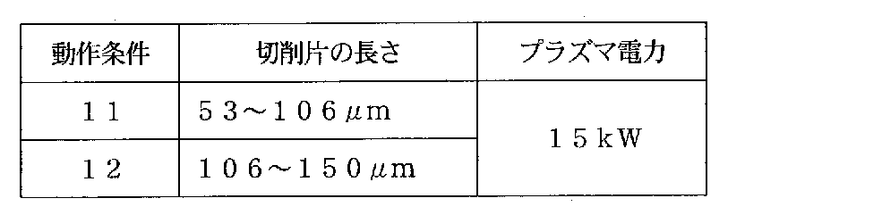
- the cut pieces of the TiAl intermetallic compound were spheroidized under the operating conditions 11 and 12 in Table 3 to produce TiAl intermetallic compound powder.
- the cutting piece was needle-like, and its length was adjusted as shown in Table 3.
- the appearance of this cutting piece is shown in the scanning electron micrograph (magnification of 100 times) of FIG.
- the plasma operating condition at the time of the spheroidizing treatment was Ar gas: 86 L / min (nor) and carrier gas: Ar gas: 4 L / min (nor).
- the pressure in the chamber was a negative pressure of ⁇ 0.02 MPa with respect to the atmospheric pressure.
- another gas atomized powder of TiAl intermetallic compound different from that of Example 1 was also prepared.
- the gas atomized powder is classified to have a particle size of about 45 to 150 ⁇ m.
- the particle diameter by D50 and the area circularity in the secondary projection image of the TiAl intermetallic compound powder produced by the above-mentioned spheroidizing treatment and gas atomizing method were measured.
- the particle diameter according to D50 was measured in the same manner as in Example 1, and the area circularity was measured for 10000 TiAl intermetallic compound powders.
- the TiAl intermetallic compound powder produced by the spheroidizing treatment has an area circularity of 90% or more of the total number of individual powders under any operating conditions. It was 0.95 or more.
- the external shape of each TiAl intermetallic compound powder is shown in the scanning electron micrograph (magnification of 100 times) of FIG. In the TiAl intermetallic compound powder produced by the gas atomization method, the number of powders having an area circularity of less than 0.95 among the individual powders exceeded 20% of the whole.
- FIG. 5 is an elemental mapping diagram (magnification 100 times) when the Al concentration of the cross section of the TiAl intermetallic compound powders 11 and 12 is combined with that of the cutting pieces and analyzed by EPMA.
- an electron beam microanalyzer "JXA-8900R" manufactured by Nippon Denshi Co., Ltd. was used.
- the cutting piece displayed smaller than the actual size has its length direction facing the analysis surface (paper side).
- the cut pieces of the TiAl intermetallic compound were spheroidized under the operating conditions 21 and 22 in Table 5 to prepare TiAl intermetallic compound powder.
- the cutting piece was needle-like, and its length was adjusted as shown in Table 5. The appearance of this cutting piece is shown in the scanning electron micrograph (magnification of 100 times) of FIG.
- the plasma operating condition at the time of the spheroidizing treatment was Ar gas: 86 L / min (nor) and carrier gas: Ar gas: 4 L / min (nor).
- the pressure in the chamber was a negative pressure of ⁇ 0.02 MPa with respect to the atmospheric pressure.
- the particle diameter by D50 of the TiAl intermetallic compound powder produced by the above-mentioned spheroidizing process and the area circularity in a secondary projection image were measured.
- the particle diameter according to D50 was measured in the same manner as in Example 1, and the area circularity was measured for 10000 TiAl intermetallic compound powders.
- the TiAl intermetallic compound powder produced by the spheroidizing treatment has an area circularity of 90% or more of the total number of individual powders under any operating conditions. It was 0.95 or more.
- the external shape of each TiAl intermetallic compound powder is shown in the scanning electron micrograph (magnification of 100 times) of FIG. It can be seen from FIG. 6 that the powder having a high maximum output at the time of the spheroidizing treatment has a high sphericity.
- FIG. 7 is an elemental mapping diagram (magnification 100 times) when the Al concentration of the cross section of the TiAl intermetallic compound powder 21 and 22 is combined with that of the cutting pieces and analyzed by EPMA as in FIG.
Landscapes
- Chemical & Material Sciences (AREA)
- Engineering & Computer Science (AREA)
- Materials Engineering (AREA)
- Mechanical Engineering (AREA)
- Metallurgy (AREA)
- Organic Chemistry (AREA)
- Physics & Mathematics (AREA)
- Thermal Sciences (AREA)
- Nanotechnology (AREA)
- Manufacture Of Metal Powder And Suspensions Thereof (AREA)
- Powder Metallurgy (AREA)
Abstract
Description
ところで、TiAl金属間化合物は、延性に乏しく、機械加工が難しい材料である。よって、所定の形状を有したTiAl金属間化合物を作製するときには、TiAl金属間化合物の粉末を準備して、これを各種の粉末冶金法(例えば、焼結、熱間静水圧プレス、金属粉末射出成形)や積層造形法(3Dプリンティングや付加製造技術(additive manufacturing)とも呼ばれる)によってニアネットシェイプに成形する手法が現実的である。そして、このニアネットシェイプに成形されたTiAl金属間化合物の表面に切削加工を行って、各種部品の最終形状に仕上げる手法が現実的である。
しかし、このような手法で得られた成形品であっても、その強度の向上には改善の余地がある。つまり、TiAl金属間化合物粉末の内部に多くの気孔(空隙)があると、成形品の内部においても、上記の気孔に起因した空隙が少なからず残留して、成形品の機械的特性や信頼性を低下させ得る。
・上記の切削片の大きさが500μm以下である。
・上記の熱プラズマ炎の電力が10~250kWである。
・上記の熱プラズマ炎が高周波プラズマ炎である。
・上記の熱プラズマ炎の動作ガスが不活性ガスである。
・上記の熱プラズマ炎の領域に上記の切削片を供給するために使用するキャリアガスが不活性ガスである。
・二次投影像における面積円形度が、全体の90%以上の個数において、0.9以上である。
・粒子径が、体積基準の累積粒度分布の50%粒子径(D50)で1~250μmである。
・成分組成が、質量%で、Al:10~80%、残部Tiおよび不純物である。そして、さらに、Nb:20.0%以下、Cr:20.0%以下のうちの1種または2種の元素種を含むか、または、V、Ta、Mn、B、Si、C、W、Yのうちの1種または2種以上の元素種を、それぞれ20.0%以下含む。
・粉末冶金法または積層造形法に用いられる。
従来、TiAl金属間化合物粉末は、「TiAl金属間化合物を主成分とする合金を溶解し、前記溶解で得られる液滴を急冷凝固させて金属粉末を得る」手法によって製造されてきた。そして、この従来の手法について、具合的に提案されていた手法は、「プラズマ回転電極法」や「ガスアトマイズ法」であった(特許文献1)。
プラズマ回転電極法によれば、まず、TiAl金属間化合物の母材(インゴット)が出発材料として準備される。そして、この母材を回転電極として、この回転する電極の先端部に、直接、プラズマを照射することで、母材の先端部が溶融したTiAl金属間化合物の成分組成を有する液滴が飛散する。そして、この飛散した液滴が凝固して、TiAl金属間化合物粉末が得られることとなる。
また、ガスアトマイズ法によれば、TiAl金属間化合物の成分組成を有した溶湯が出発材料として準備される。そして、この溶湯の細流にガスの高圧ジェットを当てることで飛散した液滴が凝固して、TiAl金属間化合物粉末が得られることとなる。
そして、ガスアトマイズ法の場合、アルゴン等の不活性ガス(冷却ガス)を吹き付けながら、溶湯を液滴化し、凝固させるため、内部にガスを巻き込み、凝固後の粉末内部に多くの気孔が形成されやすい。
加えて、上記の切削片であれば、大きな素材を直接粉砕するために、素材の水素脆化と粉砕とを組合せて得た「粉砕片」のように、初期(出発材料)の水素含有量が上昇することがないので、TiAl金属間化合物粉末中の水素含有量の低減化にも有利である。そして、このことによって、水素含有量が0.1質量%未満のTiAl金属間化合物粉末を容易に得ることができる。
なお、上記の二次投影像における面積円形度は、二次投影像における円相当径が1μm以上のTiAl金属間化合物粉末について測定することができる。
一方で、動作中の熱プラズマ炎の電力の上限については、格段の制限はない。ただし、例えば、250kW以下とすることができる。また、200kW以下や150kW以下、100kW以下とすることができる。さらに、50kW以下や40kW以下、30kW以下とすることができる。そして、熱プラズマ炎の電力を低くすることで、TiAl金属間化合物の主要成分であるAlの過剰な揮発量を少なくすることができる。好ましくは20kW以下、より好ましくは17kW以下、さらに好ましくは14kW以下である。これによって出発材料からの成分変動を抑制することができる。また、製造されたTiAl金属間化合物粉末の個々の間で生じ得るAl濃度の差も抑制することができる。
熱プラズマを発生させるときの「動作ガス」は、反応性が低いアルゴン等の不活性ガスを用いることが好ましい。不活性ガスとは、混合ガスではなく、不純物を除き不活性ガスからなるものを言う。動作ガスには水素を用いることも可能である。但し、この場合、凝固後のTiAl金属間化合物粉末中の水素含有量が上昇する場合がある。そして、水素含有量が規制されたTiAl金属間化合物粉末を得たい場合、凝固後のTiAl金属間化合物粉末を減圧雰囲気中や真空中で加熱する等の、脱水素処理を要する。よって、上記の動作ガスは、不活性ガスであることが好ましい。このことによって、TiAl金属間化合物粉末の水素含有量を、例えば、0.002質量%以下や、0.001質量%以下にまで低減することもできる。
これらの動作ガスは、切削片を熱プラズマ炎の領域に供給するために使用するキャリアガスとしても利用することができる。
TiAl金属間化合物の粉末を用いて、これを各種の粉末冶金法や積層造形法によって成形するときに、粉末内部の気孔を予め低減しておけば、成形品内部の気孔も低減できるので、成形品の強度を向上させるのに効果的である。具体的には、粉末の断面積に占める気孔部分の面積の比率(つまり、粉末の断面における気孔率)が「0~0.4面積%」のTiAl金属間化合物粉末である。好ましくは0.3面積%以下である。より好ましくは0.2面積%以下である。更に好ましくは0.1面積%以下である。そして、これらの気孔率は、上述した本発明のTiAl金属間化合物粉末の製造方法によって達成することが可能である。
Nbについて、好ましくは0.1%以上、より好ましくは1.0%以上、さらに好ましくは2.0%以上、よりさらに好ましくは3.0%以上、特に好ましくは4.0%以上である。また、Nbについて、好ましくは16.0%以下、より好ましくは13.0%以下、さらに好ましくは10.0%以下、よりさらに好ましくは6.0%以下である。
そして、Crについて、好ましくは0.1%以上、より好ましくは0.5%以上、さらに好ましくは1.0%以上、よりさらに好ましくは1.5%以上、特に好ましくは2.0%以上である。また、Crについて、好ましくは16.0%以下、より好ましくは13.0%以下、さらに好ましくは10.0%以下、よりさらに好ましくは6.0%以下、特に好ましくは3.0%以下である。
以上の成分組成は、TiAl金属間化合物粉末を0.1g以上採取して、これを測定して得ることができる。
また、この熱プラズマ処理装置は、高周波コイル3の内側に発生させた熱プラズマ炎5中に、キャリアガスとともに、出発材料である小片を供給する粉末供給ノズル6と、熱プラズマ炎5の下流側に設けたチャンバー7と、チャンバー7からの排気を行う排気装置8とを具備している。
切削片は、表2に示す成分組成のインゴットを出発材料として、これを切削することで準備した。切削片は針状であり、その長さは、粉砕および分級を行うことによって、45~200μm前後に調整した。球状化処理時のプラズマ動作条件は、表1の通りとした。なお、チャンバー7内の圧力は、大気圧に対し-0.02MPaの負圧とした。

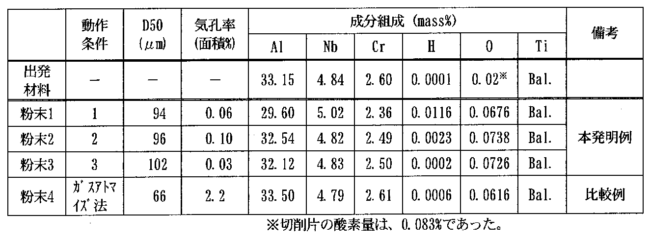
そして、本発明例の粉末1~3の成分組成を評価すれば、球状化処理のときの最大出力が低い粉末2、3の成分組成(Al含有量)は、出発材料の成分組成からの変動が小さかった。また、球状化処理のときの動作ガスに水素を使用しなかった粉末3は、水素含有量が低かった。
また、この一方で、実施例1とは別の、TiAl金属間化合物のガスアトマイズ粉末も準備した。このガスアトマイズ粉末は、粒子径が約45~150μmになるよう分級されたものである。
なお、ガスアトマイズ法で作製したTiAl金属間化合物粉末は、その個々の粉末のうち、面積円形度が0.95未満である粉末の個数が全体の20%を超えていた。

この白黒で表示された元素マッピング図(実際には、図中に示した“色分けによる”Al成分の濃度指標に従って、カラーで表示されている。)において、切削片の色調と比べて、概ね色調の薄い粉末が、Al濃度の低い粉末(つまり、球状化処理中にAl成分が揮発した粉末)である。そして、このようなAl濃度の低い粉末が、粒径の小さいものに多く確認されることがわかる。


2 プラズマ発生空間
3 高周波コイル
4 動作ガス供給部
5 熱プラズマ炎
6 粉末供給ノズル
7 チャンバー
8 排気装置
Claims (13)
- TiAl金属間化合物の切削片を、熱プラズマ炎に通過させて球状化処理することを特徴とするTiAl金属間化合物粉末の製造方法。
- 前記切削片の大きさが500μm以下であることを特徴とする請求項1に記載のTiAl金属間化合物粉末の製造方法。
- 前記熱プラズマ炎の電力が10~250kWであることを特徴とする請求項1または2に記載のTiAl金属間化合物粉末の製造方法。
- 前記熱プラズマ炎が高周波プラズマ炎であることを特徴とする請求項1ないし3のいずれかに記載のTiAl金属間化合物粉末の製造方法。
- 前記熱プラズマ炎の動作ガスが不活性ガスであることを特徴とする請求項1ないし4のいずれかに記載のTiAl金属間化合物粉末の製造方法。
- 前記熱プラズマ炎の領域に前記切削片を供給するために使用するキャリアガスが不活性ガスであることを特徴とする請求項1ないし5のいずれかに記載のTiAl金属間化合物粉末の製造方法。
- 断面における気孔率が0~0.4面積%であることを特徴とするTiAl金属間化合物粉末。
- 二次投影像における面積円形度が、全体の90%以上の個数において、0.9以上であることを特徴とする請求項7に記載のTiAl金属間化合物粉末。
- 粒子径が、体積基準の累積粒度分布の50%粒子径(D50)で1~250μmであることを特徴とする請求項7または8に記載のTiAl金属間化合物粉末。
- 成分組成が、質量%で、Al:10~80%、残部Tiおよび不純物であることを特徴とする請求項7ないし9のいずれかに記載のTiAl金属間化合物粉末。
- 前記成分組成が、質量%で、さらに、Nb:20.0%以下、Cr:20.0%以下のうちの1種または2種の元素種を含むことを特徴とする請求項10に記載のTiAl金属間化合物粉末。
- 前記成分組成が、質量%で、さらに、V、Ta、Mn、B、Si、C、W、Yのうちの1種または2種以上の元素種を、それぞれ20.0%以下含むことを特徴とする請求項10または11に記載のTiAl金属間化合物粉末。
- 粉末冶金法または積層造形法に用いられることを特徴とする請求項7ないし12のいずれかに記載のTiAl金属間化合物粉末。
Priority Applications (6)
| Application Number | Priority Date | Filing Date | Title |
|---|---|---|---|
| CN201880079156.XA CN111465462A (zh) | 2017-12-18 | 2018-12-18 | TiAl金属间化合物粉末的制造方法及TiAl金属间化合物粉末 |
| JP2019537317A JP6703759B2 (ja) | 2017-12-18 | 2018-12-18 | TiAl金属間化合物粉末の製造方法およびTiAl金属間化合物粉末 |
| US16/954,191 US20210162497A1 (en) | 2017-12-18 | 2018-12-18 | Method for producing tial intermetallic compound powder and tial intermetallic compound powder |
| CA3084769A CA3084769C (en) | 2017-12-18 | 2018-12-18 | Method for producing tial intermetallic compound powder, and tial intermetallic compound powder |
| SG11202005142XA SG11202005142XA (en) | 2017-12-18 | 2018-12-18 | Method for producing tial intermetallic compound powder, and tial intermetallic compound powder |
| EP18891799.1A EP3730237A4 (en) | 2017-12-18 | 2018-12-18 | METHOD FOR PRODUCING TIAL INTERMETAL COMPOSITE POWDER AND TIAL INTERMETAL COMPOSITE POWDER |
Applications Claiming Priority (2)
| Application Number | Priority Date | Filing Date | Title |
|---|---|---|---|
| JP2017241301 | 2017-12-18 | ||
| JP2017-241301 | 2017-12-18 |
Publications (1)
| Publication Number | Publication Date |
|---|---|
| WO2019124344A1 true WO2019124344A1 (ja) | 2019-06-27 |
Family
ID=66993646
Family Applications (1)
| Application Number | Title | Priority Date | Filing Date |
|---|---|---|---|
| PCT/JP2018/046501 Ceased WO2019124344A1 (ja) | 2017-12-18 | 2018-12-18 | TiAl金属間化合物粉末の製造方法およびTiAl金属間化合物粉末 |
Country Status (7)
| Country | Link |
|---|---|
| US (1) | US20210162497A1 (ja) |
| EP (1) | EP3730237A4 (ja) |
| JP (1) | JP6703759B2 (ja) |
| CN (1) | CN111465462A (ja) |
| CA (1) | CA3084769C (ja) |
| SG (1) | SG11202005142XA (ja) |
| WO (1) | WO2019124344A1 (ja) |
Cited By (11)
| Publication number | Priority date | Publication date | Assignee | Title |
|---|---|---|---|---|
| CN110643877A (zh) * | 2019-09-09 | 2020-01-03 | 中国航发北京航空材料研究院 | 一种含W、Mn、Si、B、C及稀土元素的TiAl金属间化合物 |
| WO2021066142A1 (ja) * | 2019-10-03 | 2021-04-08 | 東京都公立大学法人 | 耐熱合金、耐熱合金粉末、耐熱合金成形体およびその製造方法 |
| JP2023034814A (ja) * | 2021-08-31 | 2023-03-13 | トーホーテック株式会社 | TiAl金属間化合物粉の製造方法、TiAl金属間化合物粉、及び球状TiAl金属間化合物粉の製造方法 |
| JP2023512391A (ja) * | 2019-11-18 | 2023-03-27 | シックスケー インコーポレイテッド | 球形粉体用の特異な供給原料及び製造方法 |
| US12040162B2 (en) | 2022-06-09 | 2024-07-16 | 6K Inc. | Plasma apparatus and methods for processing feed material utilizing an upstream swirl module and composite gas flows |
| US12094688B2 (en) | 2022-08-25 | 2024-09-17 | 6K Inc. | Plasma apparatus and methods for processing feed material utilizing a powder ingress preventor (PIP) |
| US12176529B2 (en) | 2020-06-25 | 2024-12-24 | 6K Inc. | Microcomposite alloy structure |
| US12195338B2 (en) | 2022-12-15 | 2025-01-14 | 6K Inc. | Systems, methods, and device for pyrolysis of methane in a microwave plasma for hydrogen and structured carbon powder production |
| US12261023B2 (en) | 2022-05-23 | 2025-03-25 | 6K Inc. | Microwave plasma apparatus and methods for processing materials using an interior liner |
| US12311447B2 (en) | 2018-06-19 | 2025-05-27 | 6K Inc. | Process for producing spheroidized powder from feedstock materials |
| US12406829B2 (en) | 2021-01-11 | 2025-09-02 | 6K Inc. | Methods and systems for reclamation of Li-ion cathode materials using microwave plasma processing |
Families Citing this family (4)
| Publication number | Priority date | Publication date | Assignee | Title |
|---|---|---|---|---|
| JP7233658B2 (ja) * | 2019-03-18 | 2023-03-07 | 株式会社Ihi | 熱間鍛造用のチタンアルミナイド合金材及びチタンアルミナイド合金材の鍛造方法 |
| CN114309621B (zh) * | 2021-12-28 | 2023-11-10 | 云航时代(重庆)科技有限公司 | 一种含有难熔金属元素的微细TiAl合金球形粉体的制备方法 |
| CN114472911B (zh) * | 2022-04-02 | 2022-08-05 | 西安欧中材料科技有限公司 | 制备合金粉末的装置、方法及应用该粉末制备靶材的方法 |
| CN115386780B (zh) * | 2022-09-13 | 2023-03-21 | 南京工业大学 | 一种轻质高强高韧高熵超合金及其制备方法 |
Citations (6)
| Publication number | Priority date | Publication date | Assignee | Title |
|---|---|---|---|---|
| JPH02156003A (ja) * | 1988-12-07 | 1990-06-15 | Nippon Steel Weld Prod & Eng Co Ltd | チタン・アルミニウム金属間化合物を含む合金粉末の製造方法 |
| JP2001342506A (ja) * | 2000-05-31 | 2001-12-14 | Hitachi Metals Ltd | 粉末原料の製造方法およびターゲット材の製造方法 |
| JP2003049201A (ja) * | 2001-08-03 | 2003-02-21 | High Frequency Heattreat Co Ltd | 金属及び金属系化合物の球状粉末とその製造方法 |
| JP2008208432A (ja) | 2007-02-27 | 2008-09-11 | Kinzoku Giken Kk | TiAl金属間化合物基合金の粉末焼結体の製造方法 |
| JP2009221603A (ja) * | 2008-02-20 | 2009-10-01 | Hitachi Metals Ltd | 球状チタン合金粉末の製造方法 |
| JP2016532773A (ja) * | 2013-07-04 | 2016-10-20 | サフラン エアークラフト エンジンズ | 高エネルギービームと共に目標方法/材料の組合せに適した粉体を用いる、粉体粒子の融解又は焼結による部品の付加的な製造方法 |
Family Cites Families (11)
| Publication number | Priority date | Publication date | Assignee | Title |
|---|---|---|---|---|
| JPH04131309A (ja) * | 1990-09-21 | 1992-05-06 | Showa Denko Kk | チタンフレークの製造方法 |
| JP3113144B2 (ja) * | 1994-04-08 | 2000-11-27 | 新日本製鐵株式会社 | 高密度焼結チタン合金の製造方法 |
| JP2009287105A (ja) * | 2008-05-30 | 2009-12-10 | Hitachi Metals Ltd | 球状チタン系粉末の製造方法 |
| CN101850424B (zh) * | 2010-05-26 | 2011-07-20 | 北京科技大学 | 一种大量制备微细球形钛铝基合金粉的方法 |
| CN102717086B (zh) * | 2012-07-04 | 2014-09-17 | 北京科技大学 | 一种短流程制备高铌钛铝合金球形微粉的方法 |
| CN103752836B (zh) * | 2014-01-16 | 2015-10-21 | 北京科技大学 | 一种制备细粒径球形铌钛基合金粉末的方法 |
| CN104174856B (zh) * | 2014-08-29 | 2016-03-30 | 中国科学院重庆绿色智能技术研究院 | 制备TiAl基复合粉体材料的方法 |
| JP6652276B2 (ja) * | 2014-09-30 | 2020-02-19 | Jx金属株式会社 | Ti−Al合金スパッタリングターゲット |
| JP6402163B2 (ja) * | 2016-12-07 | 2018-10-10 | 三菱重工航空エンジン株式会社 | TiAl合金体の水素化脱水素化方法及びTiAl合金粉末の製造方法 |
| CN107130139B (zh) * | 2017-06-15 | 2018-09-18 | 北京科技大学 | 一种添加Sn强化烧结粉末冶金TiAl基合金的方法 |
| WO2019246257A1 (en) * | 2018-06-19 | 2019-12-26 | Amastan Technologies Inc. | Process for producing spheroidized powder from feedstock materials |
-
2018
- 2018-12-18 CN CN201880079156.XA patent/CN111465462A/zh active Pending
- 2018-12-18 WO PCT/JP2018/046501 patent/WO2019124344A1/ja not_active Ceased
- 2018-12-18 CA CA3084769A patent/CA3084769C/en active Active
- 2018-12-18 JP JP2019537317A patent/JP6703759B2/ja active Active
- 2018-12-18 EP EP18891799.1A patent/EP3730237A4/en not_active Withdrawn
- 2018-12-18 US US16/954,191 patent/US20210162497A1/en not_active Abandoned
- 2018-12-18 SG SG11202005142XA patent/SG11202005142XA/en unknown
Patent Citations (6)
| Publication number | Priority date | Publication date | Assignee | Title |
|---|---|---|---|---|
| JPH02156003A (ja) * | 1988-12-07 | 1990-06-15 | Nippon Steel Weld Prod & Eng Co Ltd | チタン・アルミニウム金属間化合物を含む合金粉末の製造方法 |
| JP2001342506A (ja) * | 2000-05-31 | 2001-12-14 | Hitachi Metals Ltd | 粉末原料の製造方法およびターゲット材の製造方法 |
| JP2003049201A (ja) * | 2001-08-03 | 2003-02-21 | High Frequency Heattreat Co Ltd | 金属及び金属系化合物の球状粉末とその製造方法 |
| JP2008208432A (ja) | 2007-02-27 | 2008-09-11 | Kinzoku Giken Kk | TiAl金属間化合物基合金の粉末焼結体の製造方法 |
| JP2009221603A (ja) * | 2008-02-20 | 2009-10-01 | Hitachi Metals Ltd | 球状チタン合金粉末の製造方法 |
| JP2016532773A (ja) * | 2013-07-04 | 2016-10-20 | サフラン エアークラフト エンジンズ | 高エネルギービームと共に目標方法/材料の組合せに適した粉体を用いる、粉体粒子の融解又は焼結による部品の付加的な製造方法 |
Non-Patent Citations (1)
| Title |
|---|
| See also references of EP3730237A4 |
Cited By (16)
| Publication number | Priority date | Publication date | Assignee | Title |
|---|---|---|---|---|
| US12311447B2 (en) | 2018-06-19 | 2025-05-27 | 6K Inc. | Process for producing spheroidized powder from feedstock materials |
| CN110643877A (zh) * | 2019-09-09 | 2020-01-03 | 中国航发北京航空材料研究院 | 一种含W、Mn、Si、B、C及稀土元素的TiAl金属间化合物 |
| WO2021066142A1 (ja) * | 2019-10-03 | 2021-04-08 | 東京都公立大学法人 | 耐熱合金、耐熱合金粉末、耐熱合金成形体およびその製造方法 |
| JPWO2021066142A1 (ja) * | 2019-10-03 | 2021-04-08 | ||
| US11846006B2 (en) | 2019-10-03 | 2023-12-19 | Tokyo Metropolitan Public University Corporation | Heat-resistant alloy, heat-resistant alloy powder, heat-resistant alloy structural component, and manufacturing method of the same |
| JP7696141B2 (ja) | 2019-10-03 | 2025-06-20 | 東京都公立大学法人 | 耐熱合金、積層造形用の耐熱合金粉末、耐熱合金積層造形成形体およびその製造方法 |
| US12139776B2 (en) | 2019-10-03 | 2024-11-12 | Tokyo Metropolitan Public University Corporation | Heat-resistant alloy, heat-resistant alloy powder, heat-resistant alloy structural component, and manufacturing method of the same |
| JP2023512391A (ja) * | 2019-11-18 | 2023-03-27 | シックスケー インコーポレイテッド | 球形粉体用の特異な供給原料及び製造方法 |
| US12176529B2 (en) | 2020-06-25 | 2024-12-24 | 6K Inc. | Microcomposite alloy structure |
| US12406829B2 (en) | 2021-01-11 | 2025-09-02 | 6K Inc. | Methods and systems for reclamation of Li-ion cathode materials using microwave plasma processing |
| JP2023034814A (ja) * | 2021-08-31 | 2023-03-13 | トーホーテック株式会社 | TiAl金属間化合物粉の製造方法、TiAl金属間化合物粉、及び球状TiAl金属間化合物粉の製造方法 |
| JP7403135B2 (ja) | 2021-08-31 | 2023-12-22 | トーホーテック株式会社 | TiAl金属間化合物粉の製造方法、TiAl金属間化合物粉、及び球状TiAl金属間化合物粉の製造方法 |
| US12261023B2 (en) | 2022-05-23 | 2025-03-25 | 6K Inc. | Microwave plasma apparatus and methods for processing materials using an interior liner |
| US12040162B2 (en) | 2022-06-09 | 2024-07-16 | 6K Inc. | Plasma apparatus and methods for processing feed material utilizing an upstream swirl module and composite gas flows |
| US12094688B2 (en) | 2022-08-25 | 2024-09-17 | 6K Inc. | Plasma apparatus and methods for processing feed material utilizing a powder ingress preventor (PIP) |
| US12195338B2 (en) | 2022-12-15 | 2025-01-14 | 6K Inc. | Systems, methods, and device for pyrolysis of methane in a microwave plasma for hydrogen and structured carbon powder production |
Also Published As
| Publication number | Publication date |
|---|---|
| SG11202005142XA (en) | 2020-07-29 |
| EP3730237A4 (en) | 2021-08-25 |
| CA3084769A1 (en) | 2019-06-27 |
| JP6703759B2 (ja) | 2020-06-03 |
| EP3730237A1 (en) | 2020-10-28 |
| JPWO2019124344A1 (ja) | 2019-12-19 |
| CN111465462A (zh) | 2020-07-28 |
| CA3084769C (en) | 2023-01-24 |
| US20210162497A1 (en) | 2021-06-03 |
Similar Documents
| Publication | Publication Date | Title |
|---|---|---|
| JP6703759B2 (ja) | TiAl金属間化合物粉末の製造方法およびTiAl金属間化合物粉末 | |
| Sun et al. | Review of the methods for production of spherical Ti and Ti alloy powder | |
| KR102722473B1 (ko) | 알루미늄 합금 부품 제조 공정 | |
| CN112805105B (zh) | 制造铝合金零件的方法 | |
| US20210156005A1 (en) | Process for manufacturing an aluminum alloy part | |
| CN112805106B (zh) | 制造铝合金零件的方法 | |
| CN105764634B (zh) | 采用适用于目标方法/材料对的粉末,通过用高能束熔融或烧结粉末颗粒来叠加制造部件的方法 | |
| JP7386819B2 (ja) | アルミニウム合金からなる部品の製造方法 | |
| US11821059B2 (en) | Ni-based alloy, Ni-based alloy powder, Ni-based alloy member, and product including Ni-based alloy member | |
| CN113412172A (zh) | 制造铝合金零件的方法 | |
| CN114641357A (zh) | 用于制造三维物体的球形粉末 | |
| Enneti et al. | Direct metal laser sintering/selective laser melting of tungsten powders | |
| WO2018122937A1 (ja) | 金属積層造形物、金属積層造形用のアルミニウム系粉末およびその製造方法 | |
| US11713496B2 (en) | Powder material, powder material for additive manufacturing, and method for producing powder material | |
| US20220331858A1 (en) | SPHERICAL Ti-BASED POWDER AND MANUFACTURING METHOD THEREFOR | |
| JP7296232B2 (ja) | 中実球状粉末の製造方法及び造形製品の製造方法 | |
| JP2021075736A (ja) | Cr基合金付加加工物およびその製造方法、ならびにCr基合金粉末の製造方法 | |
| JP7378907B2 (ja) | 3d造形用混合粉末の製造方法 | |
| JP7763997B1 (ja) | 銅合金粉末、及び該銅合金粉を用いた積層造形物の製造方法 | |
| Shah et al. | of AlSi10Mg Alloy Produced by DMLS | |
| Shah et al. | Mechanical Properties, Microstructural and Surface Topography Evaluation of AlSi10Mg Alloy Produced by DMLS Process | |
| JP2025056621A (ja) | 低熱膨張積層合金 | |
| JP2021075737A (ja) | Cr基合金付加加工物およびその製造方法、ならびにCr基合金粉末の製造方法 | |
| WO2023162524A1 (ja) | 3d造形用混合粉末の製造方法 | |
| JP2023126112A (ja) | Cu合金及び3D造形体 |
Legal Events
| Date | Code | Title | Description |
|---|---|---|---|
| ENP | Entry into the national phase |
Ref document number: 2019537317 Country of ref document: JP Kind code of ref document: A |
|
| 121 | Ep: the epo has been informed by wipo that ep was designated in this application |
Ref document number: 18891799 Country of ref document: EP Kind code of ref document: A1 |
|
| ENP | Entry into the national phase |
Ref document number: 3084769 Country of ref document: CA |
|
| NENP | Non-entry into the national phase |
Ref country code: DE |
|
| ENP | Entry into the national phase |
Ref document number: 2018891799 Country of ref document: EP Effective date: 20200720 |