WO2019130663A1 - X線検査装置 - Google Patents
X線検査装置 Download PDFInfo
- Publication number
- WO2019130663A1 WO2019130663A1 PCT/JP2018/032810 JP2018032810W WO2019130663A1 WO 2019130663 A1 WO2019130663 A1 WO 2019130663A1 JP 2018032810 W JP2018032810 W JP 2018032810W WO 2019130663 A1 WO2019130663 A1 WO 2019130663A1
- Authority
- WO
- WIPO (PCT)
- Prior art keywords
- sample
- ray
- axis
- measurement
- unit
- Prior art date
- Legal status (The legal status is an assumption and is not a legal conclusion. Google has not performed a legal analysis and makes no representation as to the accuracy of the status listed.)
- Ceased
Links
Images



Classifications
-
- G—PHYSICS
- G01—MEASURING; TESTING
- G01N—INVESTIGATING OR ANALYSING MATERIALS BY DETERMINING THEIR CHEMICAL OR PHYSICAL PROPERTIES
- G01N23/00—Investigating or analysing materials by the use of wave or particle radiation, e.g. X-rays or neutrons, not covered by groups G01N3/00 – G01N17/00, G01N21/00 or G01N22/00
- G01N23/20—Investigating or analysing materials by the use of wave or particle radiation, e.g. X-rays or neutrons, not covered by groups G01N3/00 – G01N17/00, G01N21/00 or G01N22/00 by using diffraction of the radiation by the materials, e.g. for investigating crystal structure; by using scattering of the radiation by the materials, e.g. for investigating non-crystalline materials; by using reflection of the radiation by the materials
- G01N23/20008—Constructional details of analysers, e.g. characterised by X-ray source, detector or optical system; Accessories therefor; Preparing specimens therefor
- G01N23/20016—Goniometers
-
- G—PHYSICS
- G01—MEASURING; TESTING
- G01N—INVESTIGATING OR ANALYSING MATERIALS BY DETERMINING THEIR CHEMICAL OR PHYSICAL PROPERTIES
- G01N23/00—Investigating or analysing materials by the use of wave or particle radiation, e.g. X-rays or neutrons, not covered by groups G01N3/00 – G01N17/00, G01N21/00 or G01N22/00
- G01N23/20—Investigating or analysing materials by the use of wave or particle radiation, e.g. X-rays or neutrons, not covered by groups G01N3/00 – G01N17/00, G01N21/00 or G01N22/00 by using diffraction of the radiation by the materials, e.g. for investigating crystal structure; by using scattering of the radiation by the materials, e.g. for investigating non-crystalline materials; by using reflection of the radiation by the materials
- G01N23/207—Diffractometry using detectors, e.g. using a probe in a central position and one or more displaceable detectors in circumferential positions
-
- G—PHYSICS
- G01—MEASURING; TESTING
- G01N—INVESTIGATING OR ANALYSING MATERIALS BY DETERMINING THEIR CHEMICAL OR PHYSICAL PROPERTIES
- G01N2223/00—Investigating materials by wave or particle radiation
- G01N2223/05—Investigating materials by wave or particle radiation by diffraction, scatter or reflection
- G01N2223/056—Investigating materials by wave or particle radiation by diffraction, scatter or reflection diffraction
-
- G—PHYSICS
- G01—MEASURING; TESTING
- G01N—INVESTIGATING OR ANALYSING MATERIALS BY DETERMINING THEIR CHEMICAL OR PHYSICAL PROPERTIES
- G01N2223/00—Investigating materials by wave or particle radiation
- G01N2223/30—Accessories, mechanical or electrical features
- G01N2223/33—Accessories, mechanical or electrical features scanning, i.e. relative motion for measurement of successive object-parts
- G01N2223/3306—Accessories, mechanical or electrical features scanning, i.e. relative motion for measurement of successive object-parts object rotates
-
- G—PHYSICS
- G01—MEASURING; TESTING
- G01N—INVESTIGATING OR ANALYSING MATERIALS BY DETERMINING THEIR CHEMICAL OR PHYSICAL PROPERTIES
- G01N2223/00—Investigating materials by wave or particle radiation
- G01N2223/30—Accessories, mechanical or electrical features
- G01N2223/33—Accessories, mechanical or electrical features scanning, i.e. relative motion for measurement of successive object-parts
- G01N2223/3308—Accessories, mechanical or electrical features scanning, i.e. relative motion for measurement of successive object-parts object translates
-
- G—PHYSICS
- G01—MEASURING; TESTING
- G01N—INVESTIGATING OR ANALYSING MATERIALS BY DETERMINING THEIR CHEMICAL OR PHYSICAL PROPERTIES
- G01N2223/00—Investigating materials by wave or particle radiation
- G01N2223/30—Accessories, mechanical or electrical features
- G01N2223/331—Accessories, mechanical or electrical features rocking curve analysis
-
- G—PHYSICS
- G01—MEASURING; TESTING
- G01N—INVESTIGATING OR ANALYSING MATERIALS BY DETERMINING THEIR CHEMICAL OR PHYSICAL PROPERTIES
- G01N2223/00—Investigating materials by wave or particle radiation
- G01N2223/50—Detectors
-
- G—PHYSICS
- G01—MEASURING; TESTING
- G01N—INVESTIGATING OR ANALYSING MATERIALS BY DETERMINING THEIR CHEMICAL OR PHYSICAL PROPERTIES
- G01N2223/00—Investigating materials by wave or particle radiation
- G01N2223/60—Specific applications or type of materials
- G01N2223/611—Specific applications or type of materials patterned objects; electronic devices
- G01N2223/6116—Specific applications or type of materials patterned objects; electronic devices semiconductor wafer
-
- G—PHYSICS
- G01—MEASURING; TESTING
- G01N—INVESTIGATING OR ANALYSING MATERIALS BY DETERMINING THEIR CHEMICAL OR PHYSICAL PROPERTIES
- G01N2223/00—Investigating materials by wave or particle radiation
- G01N2223/60—Specific applications or type of materials
- G01N2223/645—Specific applications or type of materials quality control
Definitions
- the present invention relates to an X-ray inspection apparatus suitable for the technical field of manufacturing an element having a multilayer film structure in which a large number of thin films are stacked on a substrate, such as a semiconductor manufacturing field.
- the characteristics of an element having a multilayer film structure in which a large number of thin films are stacked on a substrate such as a semiconductor vary depending on the film thickness, density, crystallinity, and the like of the thin film to be formed. In recent years, miniaturization and integration of these devices have progressed, and the tendency has become remarkable. Therefore, a thin film inspection apparatus capable of accurately measuring the state of the formed thin film is required.
- TEM cross-sectional transmission electron microscope
- film thickness inspection apparatus using light interference and ellipsometry a film thickness inspection apparatus using light interference and ellipsometry
- photoacoustic apparatus a photoacoustic apparatus, and the like
- TEM cross-sectional transmission electron microscopy
- in-line inspection inspects a thin film to be inspected in real time by being embedded in the manufacturing process, and products extracted from the manufacturing line for inspection are discarded after inspection It was the situation.
- a film thickness inspection apparatus or photoacoustic apparatus using light interference or ellipsometry is suitable for in-line inspection, the accuracy is insufficient for measurement of a thin film of several nm.
- the present applicant incorporates the manufacturing process of a film-forming product, directly inspects the product itself, and enables in-line inspection which enables inspection of even a thin film of several nm without disposability of the wafer.
- Previously proposed an X-ray thin film inspection apparatus see Patent Document 1).
- An object of the present invention is to provide an in-line X-ray inspection apparatus capable of measuring X-ray measurement incorporating the above-described in-plane diffraction with high accuracy and high efficiency, which is incorporated in a manufacturing process.
- the X-ray inspection apparatus of the present invention A sample placement unit for placing a sample to be inspected; A sample placement unit positioning mechanism for moving the sample placement unit; A goniometer including first and second pivoting members pivoting independently; An X-ray irradiation unit mounted on the first pivoting member for condensing and irradiating an X-ray to a preset measurement point; And a two-dimensional x-ray detector mounted on the second pivoting member.
- the goniometer is And a ⁇ s pivoting mechanism which pivots the first pivoting member about the ⁇ s axis extending horizontally through the measurement point to set the incident angle of the X-ray from the X-ray irradiation unit to the sample disposed in the sample placement portion , and a ⁇ d pivoting mechanism configured to pivot the second pivoting member about the ⁇ d axis coincident with the ⁇ s axis to set a scanning angle of the X-ray detector.
- sample placement unit positioning mechanism A ⁇ rotation mechanism that rotates the sample placement unit around a ⁇ axis orthogonal to the surface of the sample placed in the sample placement unit;
- An X moving mechanism for linearly moving the sample placement portion and the ⁇ axis in the X direction intersecting at right angles with the ⁇ s axis and the ⁇ d axis;
- a Y moving mechanism for linearly moving the sample placement portion and the ⁇ axis in a Y direction orthogonal to the X direction;
- a Z moving mechanism for moving the sample placement unit in the Z direction orthogonal to the surface of the sample placed in the sample placement unit;
- a crucible rotation mechanism for rotating the sample placement portion and the ⁇ axis about a crucible axis orthogonal to the ⁇ s axis and the ⁇ d axis at the measurement point and extending in the horizontal direction;
- the sample placement portion and the ⁇ axis are rotated around the ⁇ axis orthogonal to the ⁇ axis at
- the X-ray irradiation unit condenses the X-rays in a lateral direction that is orthogonal to the optical axis of the X-rays and parallel to the ⁇ s axis, and orthogonal to the optical axis of the X-rays and also perpendicular to the ⁇ s axes X-rays are also collected in the vertical direction crossing the
- the crucible rotation mechanism is driven to vertically arrange the surface of the sample disposed in the sample placement unit, and the X-ray irradiation unit Rocking curve measurement of in-plane diffraction can be performed by irradiating the condensed X-ray and changing the incident angle of the X-ray on the sample by the ⁇ s turning mechanism.
- the diffracted X-rays appearing from the surface of the sample at a given range of diffraction angles can be collectively detected by the two-dimensional X-ray detector, measurement with high throughput can be realized.
- the above-described X-ray irradiation unit is preferably configured to condense X-rays in a half width within 100 ⁇ m in the horizontal direction and the vertical direction at the measurement point.
- the Y moving mechanism may be configured such that the direction (Y direction) in which the sample placement unit is moved is parallel to the ⁇ s axis and the ⁇ d axis, with the sample placement unit horizontally disposed by the crucible rotation mechanism. preferable.
- the Y moving mechanism functions as a sample exchange mechanism for placing the sample placement unit at the sample exchange position set in advance. It becomes possible to combine.
- the direction in which the sample placement unit is moved by the Y movement mechanism (that is, the Y direction) is parallel to the ⁇ s axis that is the turning center of the first turning member and the ⁇ d axis that is the turning center of the second turning member.
- the ⁇ rotation mechanism is mounted on the Y moving mechanism, thereby reducing the torque required for driving the ⁇ rotation mechanism. Thereby, downsizing of the ⁇ rotation mechanism and smooth driving with small power can be realized.
- the X-ray inspection apparatus controls the sample placement unit positioning mechanism, the goniometer including the first and second pivot members, and the X-ray irradiation unit to perform rocking curve measurement of in-plane diffraction. It can also be configured to include a control unit including a function.
- the control unit driving the crucible rotation mechanism to vertically arrange the surface of the sample placed in the sample placement unit;
- the Z movement mechanism is driven to adjust the inspection site of the sample placed in the sample placement unit to the height of the measurement point, Drive the ⁇ rotation mechanism, the X movement mechanism and the Y movement mechanism to position the test area of the sample at the measurement point in the preset direction, Further, the ⁇ s turning mechanism and the ⁇ rotating mechanism are driven to irradiate X-rays from the X-ray irradiation unit from a direction close to parallel to the surface of the sample, driving the ⁇ d pivoting mechanism in conjunction with the ⁇ s pivoting mechanism, and disposing the two-dimensional X-ray detector at a position at which diffracted X-rays appearing from the sample according to Bragg's law are detected; And, the ⁇ s pivoting mechanism is driven to change the incident angle of the X-ray to the sample, and the control function is carried out to perform the rocking curve measurement of the in-plane dif
- the control unit can also be configured as follows. That is, the control unit driving the crucible rotation mechanism to vertically arrange the surface of the sample placed in the sample placement unit; The Z movement mechanism is driven to adjust the inspection site of the sample placed in the sample placement unit to the height of the measurement point, Drive the ⁇ rotation mechanism, the X movement mechanism and the Y movement mechanism to position the test area of the sample at the measurement point in the preset direction, Furthermore, the ⁇ s pivoting mechanism is driven to irradiate X-rays from the X-ray irradiation unit from a direction close to parallel to the surface of the sample, driving the ⁇ d pivoting mechanism in conjunction with the ⁇ s pivoting mechanism, and disposing the two-dimensional X-ray detector at a position at which diffracted X-rays appearing from the sample according to Bragg's law are detected; And, while driving the ⁇ rotation mechanism and interlocking the X movement mechanism and the Y movement mechanism with the drive, changing the incident angle of the X-ray to the sample while holding the
- control unit can also be configured as follows. That is, the control unit driving the crucible rotation mechanism to vertically arrange the surface of the sample placed in the sample placement unit; The Z movement mechanism is driven to adjust the inspection site of the sample placed in the sample placement unit to the height of the measurement point, Drive the ⁇ rotation mechanism, the X movement mechanism and the Y movement mechanism to position the test area of the sample at the measurement point in the preset direction, Further, the ⁇ s turning mechanism and the ⁇ rotating mechanism are driven to irradiate X-rays from the X-ray irradiation unit from a direction close to parallel to the surface of the sample, driving the ⁇ d pivoting mechanism in conjunction with the ⁇ s pivoting mechanism, and disposing the two-dimensional X-ray detector at a position at which diffracted X-rays appearing from the sample according to Bragg's law are detected; It may be configured to include a control function of performing rocking curve measurement of in-plane diffraction within the range of the condensing angle of the control unit
- the X-ray inspection apparatus of the present invention controls the sample placement unit positioning mechanism, the goniometer including the first and second pivot members, and the X-ray irradiation unit to perform in-plane diffraction measurement. It can also be set as the composition provided with the control part which contains.
- control unit driving the crucible rotation mechanism to vertically arrange the surface of the sample placed in the sample placement unit;
- the Z movement mechanism is driven to adjust the inspection site of the sample placed in the sample placement unit to the height of the measurement point, Drive the ⁇ rotation mechanism, the X movement mechanism and the Y movement mechanism to position the test area of the sample at the measurement point in the preset direction, Further, the ⁇ s turning mechanism and the ⁇ rotating mechanism are driven to irradiate X-rays from the X-ray irradiation unit from a direction close to parallel to the surface of the sample, Control to perform in-plane diffraction measurement by positioning the two-dimensional X-ray detector at a position where the ⁇ d pivoting mechanism is driven in conjunction with the ⁇ s pivoting mechanism to detect the diffracted X-rays appearing from the surface of the sample according to Bragg's law Configure, including functions.
- the X-ray inspection apparatus of the present invention includes a control function of performing pole point measurement by controlling the sample positioning unit positioning mechanism, the goniometer including the first and second pivot members, and the X-ray irradiation unit.
- a configuration provided with a control unit is also possible.
- the control unit The elevation angle ⁇ of pole measurement is set within the range of 0 ° to 90 ° by driving the eyelid rotation mechanism and rotating the surface of the sample disposed in the sample placement portion about the eyelid axis.
- a control function that performs pole point measurement by setting the in-plane rotation angle ⁇ of pole point measurement by driving the ⁇ rotation mechanism to rotate the surface of the sample disposed in the sample placement unit around the ⁇ axis. And including.
- X-ray measurement capturing in-plane diffraction can be measured with high accuracy and high efficiency in-line by being incorporated into a manufacturing process.
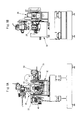
- FIG. 1A is a front view showing the entire structure of an X-ray inspection apparatus according to an embodiment of the present invention.
- FIG. 1B is also a side view.
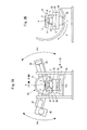
- FIG. 2A is a front view schematically showing the main structure of the X-ray inspection apparatus according to the embodiment of the present invention.
- FIG. 2B is also a side view.
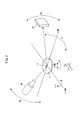
- FIG. 3 is a view schematically showing the moving direction of the sample placement unit by the sample placement unit positioning mechanism.
- FIG. 4A is a front view schematically showing the configuration of the X-ray irradiation unit according to the embodiment of the present invention.
- FIG. 4B is also a bottom view.
- FIG. 5 is a perspective view of the X-ray irradiation unit shown in FIGS. 4A and 4B.
- FIG. 6A is an enlarged front view showing the first X-ray optical element and the second X-ray optical element included in the X-ray irradiation unit shown in FIG. 4A, FIG. 4B and FIG. FIG. 6B is also a bottom view.
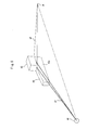
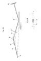
- FIG. 7A is a front view schematically showing a trajectory of X-rays irradiated from the X-ray irradiation unit to the inspection surface of the semiconductor wafer and a trajectory of diffracted X-rays reflected from the inspection surface and incident on the X-ray detector. It is.
- FIG. 7B is a plan view showing a portion of measurement point P in FIG. 7A in an enlarged manner.
- FIG. 8 is a block diagram showing a control system (control unit) of the X-ray inspection apparatus according to the embodiment of the present invention.
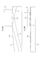
- FIG. 9 is a conceptual diagram for explaining in-plane X-ray diffraction measurement.
- FIG. 10A is a front view corresponding to FIG. 2 for describing an implementation procedure of in-plane X-ray diffraction measurement by the X-ray inspection apparatus according to the embodiment of the present invention.
- FIG. 10B is also a side view.
- FIG. 11 is a schematic view corresponding to FIG. 3 for explaining an implementation procedure of in-plane X-ray diffraction measurement by the X-ray inspection apparatus according to the embodiment of the present invention.
- FIG. 10A is a front view corresponding to FIG. 2 for describing an implementation procedure of in-plane X-ray diffraction measurement by the X-ray inspection apparatus according to the embodiment of the present invention.
- FIG. 10B is also a side view.
- FIG. 11 is a
- FIG. 12 is a conceptual diagram for explaining rocking curve measurement of in-plane diffraction.
- FIG. 13 is a conceptual diagram for explaining pole point measurement.
- FIG. 14A is a front view schematically showing another configuration example of the X-ray inspection apparatus according to the embodiment of the present invention.
- FIG. 14B is also a side view.
- FIG. 1A and FIG. 1B are views showing the entire structure of an X-ray inspection apparatus according to an embodiment of the present invention.
- 2A and 2B schematically show the main structure of the same device.
- the X-ray inspection apparatus according to the embodiment of the present invention comprises a sample stage 10, a goniometer 20, and a sample placement unit positioning mechanism (hereinafter sometimes referred to simply as a "positioning mechanism") 30, X A radiation unit 40 and an X-ray detector 50 are provided.
- a sample placement portion 11 is formed on the top surface of the sample stage 10.
- a semiconductor wafer (sample S) to be inspected is placed in the sample placement unit 11.
- the sample table 10 is driven by the positioning mechanism 30.
- Measurement points P are set in advance in the X-ray examination apparatus. Then, by driving the sample table 10 by the positioning mechanism 30, the measurement point of the sample S disposed in the sample placement unit 11 is positioned at the measurement point P.
- the sample placement unit 11 is equipped with a mechanism (not shown) for fixing the sample S.
- a mechanism (not shown) for fixing the sample S.
- dropping of the sample S from the sample setting unit 11 is prevented even when the surface of the sample setting unit 11 (upper surface of the sample table 10) is vertically arranged as described later.
- a fixing mechanism of the sample S for example, a plurality of suction nozzles are opened on the surface of the sample placement unit 11, and the hollow portion of the suction nozzle is vacuum suctioned by a suction device such as a vacuum pump.
- a suction device such as a vacuum pump.
- a configuration in which the sample S is adsorbed to the surface can be employed.
- other known sample fixing mechanisms may be employed.
- the goniometer 20 incorporates the ⁇ s turning mechanism and the ⁇ d turning mechanism in the goniometer main body 21.
- the ⁇ s pivoting mechanism pivots the first pivoting arm (pivoting member) 22 in the direction of the arrow ⁇ s in FIG. 2A about the ⁇ s axis extending in the horizontal direction through the preset measurement point P.
- An X-ray irradiation unit 40 is mounted on the first pivoting arm 22. Then, by the movement of the first pivoting arm 22, the incident angle of the X-ray from the X-ray irradiation unit 40 to the sample S is set.
- the ⁇ d pivoting mechanism pivots the second pivoting arm (pivotal member) 23 in the direction of the arrow ⁇ d in FIG. 2A about the ⁇ d axis extending in the horizontal direction through the preset measurement point P.
- An X-ray detector 50 is mounted on the second pivoting arm 23. Then, by the movement of the first pivoting arm 22, the scanning angle of the X-ray detector 50 is set. That is, the movement of the first pivoting arm 22 places the X-ray detector 50 at a position where the X-ray detector 50 detects the X-ray diffraction that appears from the surface of the sample S according to Bragg's law.
- the ⁇ s axis and the ⁇ d axis described above are coaxial pivot center axes.
- the positioning mechanism 30 includes a ⁇ rotation mechanism 31 for moving the sample placement unit 11 in each direction, an X movement mechanism 32, a Y movement mechanism 33, a Z movement mechanism 34, an eyelid rotation mechanism 35, and an ⁇ rotation mechanism 36.
- FIG. 3 is a view schematically showing the moving direction of the sample placement unit 11 by the positioning mechanism 30. As shown in FIG. The positioning mechanism 30 will be described with reference to FIG. 2 and FIGS. 2A and 2B.
- the ⁇ rotation mechanism 31 rotates the sample placement unit 11 in the direction of the arrow ⁇ in the figure around the ⁇ axis orthogonal to the surface of the sample S placed in the sample placement unit 11.
- the X moving mechanism 32 linearly moves the sample placement unit 11 and the ⁇ axis in the X direction intersecting at right angles with the ⁇ s axis and the ⁇ d axis.
- the Y moving mechanism 33 linearly moves the sample placement unit 11 and the ⁇ axis in the Y direction orthogonal to the X direction.
- the Z moving mechanism 34 moves the sample placement unit 11 in the Z direction orthogonal to the surface of the sample S placed in the sample placement unit 11.
- the crucible rotation mechanism 35 rotates the sample placement unit 11 and the ⁇ axis in the direction of the arrow ⁇ in the figure about a crucible axis orthogonal to the ⁇ s axis and the ⁇ d axis at the measurement point P and extending in the horizontal direction.
- the ⁇ rotation mechanism 36 has the sample placement portion 11 and the ⁇ axis at the arrow ⁇ in the figure, centering on the ⁇ axis orthogonal to the ⁇ axis at the measurement point P and extending parallel to the surface of the sample disposed in the sample placement portion 11. Rotate in the direction. Further, the ⁇ ⁇ rotation mechanism 36 is rotated by the ⁇ rotation mechanism 35 in the direction of the arrow ⁇ in the figure around the ⁇ axis.
- a sample exchange position (not shown) is set in advance.
- the sample placement unit 11 formed on the upper surface of the sample stage 10 is transported to the sample exchange position.
- a sample exchange device such as a robot arm takes out the inspected sample S from the sample placement unit 11 and places a new sample S to be examined to the sample placement unit 11 Ru.
- the Y moving mechanism 33 is configured to function as a sample exchange mechanism for moving the sample placement unit 11 to the sample exchange position.
- the direction (Y direction) for moving the sample placement unit 11 is configured to be parallel to the ⁇ s axis and the ⁇ d axis .
- the sample exchange position is set on the moving path of the sample placement unit 11 in the direction.
- the ⁇ rotation mechanism 31 is mounted on the Y moving mechanism 33 to reduce the torque necessary for driving the ⁇ rotation mechanism 31. Thereby, downsizing of the ⁇ rotation mechanism 31 and smooth driving with small power can be realized.
- the ⁇ rotation mechanism 36, the X movement mechanism 32, the Y movement mechanism 33, the Z movement mechanism 34, and the ⁇ rotation mechanism 31 and the sample table 10 are mounted.
- the wedge rotation mechanism 35 is configured to rotate the wedge ⁇ rotation mechanism 36 around the wedge axis.
- An X moving mechanism 32 and a Y moving mechanism 33 are mounted on the ⁇ ⁇ rotating mechanism 36.
- a Z moving mechanism 34 is mounted on the Y moving mechanism 33.
- the ⁇ rotation mechanism 31 is mounted on the Z moving mechanism 34.
- the sample table 10 is mounted on the ⁇ rotation mechanism 31.
- the X-ray irradiation unit 40 has a function of monochromating X-rays generated from the X-ray tube into characteristic X-rays of a specific wavelength and condensing the X-rays into one spot.
- the irradiation trajectory of the X-ray is adjusted so that the X-ray is condensed and irradiated to the measurement point P set in advance.
- the measurement point of the sample S placed in the sample placement unit 11 is positioned at the measurement point P.
- the detailed structure of the X-ray irradiation unit 40 will be described later.
- the X-ray detector 50 employs a two-dimensional X-ray detector.
- the two-dimensional X-ray detector has a planar X-ray detection unit configured in two dimensions, and the diffracted X-rays appearing from the surface of the sample S are grouped together in the planar X-ray detection unit. Can be recorded. Therefore, the time required for measurement can be shortened as compared with one-dimensional X-ray detectors such as a proportional counter (PC) and a scintillation counter (SC).
- PC proportional counter
- SC scintillation counter
- the X-ray irradiation unit 40 shown in FIGS. 4A to 7B includes an X-ray tube 41, a first X-ray optical element 42, a second X-ray optical element 43, and a focusing slit 44 (slit member). Contains as a component. Each of these components is incorporated in a unit body (not shown). The unit body is of compact dimensions that can be mounted on the first pivoting arm 22.
- the focusing slit 44 is shown only in FIG. 7A, and is omitted in FIGS. 4A, 4B and 5.
- a microfocus X-ray tube having an electron beam focal size on the target of about ⁇ 100 ⁇ m can be used.
- a target material copper (Cu), molybdenum (Mo), iron (Fe), cobalt (Co), tungsten (W), chromium (Cr), silver (Ag), gold (Au) etc. may be used as necessary. It can be selected.
- copper (Cu) is used as the target material, only characteristic X-rays of Cu—K ⁇ 1 having high angular resolution can be extracted by the first and second X-ray optical elements 42 and 43 described later. Therefore, X-ray thin film inspection with good throughput can be realized by irradiating the sample with the characteristic X-ray of Cu-K ⁇ 1.
- the first and second X-ray optical elements 42 and 43 receive the X-ray a1 emitted from the X-ray tube 41 and extract only characteristic X-rays of a specific wavelength, and also extract the extracted characteristic X-ray a2 as a sample It has a function of collecting light on the surface of the sample placed on the table 10.
- the first X-ray optical element 42 and the second X-ray optical element 43 are surfaces on which X-rays are incident and on which characteristic X-rays are reflected (hereinafter simply referred to as “surface” ) 42a and 43a are arranged orthogonal to each other. Then, as shown in FIG. 7A, the first X-ray optical element 42 and the second X-ray optical element 43 are square on the surface of the sample in which the characteristic X-ray a2 of the specific wavelength is disposed on the sample table 10. The light is collected so as to form a minute spot of shape.
- FIG. 7B is an enlarged plan view schematically showing the position at which the characteristic X-ray a2 is collected on the surface of the sample (semiconductor wafer).
- the first X-ray optical element 42 and the second X-ray optical element 43 are arranged by the Side-by-Side method in which one side is in contact with each other.
- the present invention is not limited thereto. It can also be arranged in series called Baez (KB).
- the measurement point P is a position at which the characteristic X-rays extracted by being reflected by the first and second X-ray optical elements 42 and 43 on the surface of the sample disposed on the sample stage 10 are collected.
- the surfaces 42a and 43a of the X-ray optical elements 42 and 43 are curved in a concave shape.
- the first X-ray optical element 42 condenses the X-rays in the vertical direction orthogonal to the optical axis of the X-rays and orthogonal to the ⁇ s axis.
- the second X-ray optical element 43 condenses the X-rays in the lateral direction orthogonal to the optical axis of the X-rays and parallel to the ⁇ s axis.
- the first X-ray optical element 42 is made of a crystalline material having high crystallinity.
- the first X-ray optical element 42 is made of a crystalline material having a very small inherent rocking curve width (ie, an angular range in which parallel beams can be reflected).
- a crystalline material having a very small inherent rocking curve width a crystalline material corresponding to a perfect crystal with extremely few lattice defects and impurities is applicable.
- the intrinsic rocking curve width is made of a crystalline material of 0.06 ° or less.
- a crystal material for example, Ge (1 1 1) or Si (1 1 1) can be used.
- Ge (1 1 1) is used, a rocking curve width of 0.06 ° or less is obtained.
- Si (1 1 1) is used, a rocking curve width of 0.02 ° or less can be obtained.
- the first X-ray optical element 42 at the measurement point P, X-rays can be focused to a half width within 100 ⁇ m in the longitudinal direction.
- the first X-ray optical element 42 has a function of extracting only characteristic X-rays of a specific wavelength and converting them into a single color.
- the second X-ray optical element 43 is constituted by a multilayer film mirror.
- the second X-ray optical element 43 has a function of extracting only characteristic X-rays of a specific wavelength and converting them into a single color.
- characteristic X-rays having the same wavelength as the characteristic X-rays extracted by the first X-ray optical element 42 are adjusted to be extracted from the second X-ray optical element 43.
- X-rays can be focused to a half width within 100 ⁇ m in the lateral direction.
- the X-ray b1 emitted from the X-ray tube 41 and incident on the surface 43a of the second X-ray optical element 43 is monochromatized by the X-ray optical element 43.
- the light is reflected and travels to be condensed laterally, and then enters the surface 42 a of the first X-ray optical element 42.
- the X-ray b2 incident on the surface 42a of the first X-ray optical element 42 is also monochromaticized and reflected in this X-ray optical element 42 and proceeds to be condensed in the vertical direction, as shown in FIG. 4A, FIG. It irradiates to the measurement point P shown to 4B.
- the X-ray c1 emitted from the X-ray tube 41 and incident on the surface 42a of the first X-ray optical element 42 is monochromaticized and reflected by the X-ray optical element 42 and condensed in the vertical direction And then enter the surface 43 a of the second X-ray optical element 43. Then, the X-ray c2 incident on the surface 43a of the second X-ray optical element 43 proceeds so as to be condensed in the lateral direction, and is irradiated to the measurement point P shown in FIGS. 4A and 4B.
- the X-ray a1 emitted from the X-ray tube 41 is reflected once each on the surface 42a of the first X-ray optical element 42 and the surface 43a of the second X-ray optical element 43 In the process, only the characteristic X-ray a2 of the specific wavelength is extracted, and the characteristic X-ray a2 is condensed on the measurement point P.
- Patent Document 2 and Patent Document 3 disclose X-ray beam adjustment systems having a configuration in which a perfect crystal and multilayer optical components are combined. However, these documents do not disclose a configuration optimized for an X-ray inspection apparatus in which a semiconductor wafer is a sample to be inspected.
- the condensing slit 44 is disposed so as to partially shield the characteristic X-rays a2 reflected by the first and second X-ray optical elements 42 and 43 from both sides in the above-described longitudinal direction.
- the focusing slit 44 has a function of limiting focusing of the focused X-ray a2 reflected by the first and second X-ray optical elements 42 and 43 in the longitudinal direction.
- the first X-ray optical element 42, the second X-ray optical element 43 and the focusing slit 44 X-rays can be focused to a minute area. Therefore, it becomes possible to perform thin film measurement by irradiating X-rays to a very minute inspection area on the surface of a semiconductor wafer.
- the first X-ray optical element 42 is made of a crystalline material having a very small inherent rocking curve width, X-ray thin film measurement can be performed by using the characteristic X-ray a2 extracted from the crystalline material. In the above, extremely high angular resolution can be obtained.
- FIG. 8 is a block diagram showing a control system (control unit) of the X-ray inspection apparatus.
- the control of the X-ray irradiation unit 40 is executed by an XG (X-ray Generator) controller 101.
- the positioning controller 102 drives and controls the positioning mechanism 30.
- the goniometer 20 is driven and controlled by the gonio controller 103.
- Each component of the XG controller 101, the positioning controller 102, and the gonio controller 103 operates based on setting information sent from the central processing unit (CPU) 100.
- the setting information is stored in advance in the storage unit 110 as a recipe, and the central processing unit (CPU) 100 reads out and outputs the read information to each of the above configuration units.
- the X-ray detector 50 is controlled by the counting control circuit 104.
- Each of these components and the central processing unit 100 are configured by a computer, and are installed in advance in the storage unit 110 to execute respective control operations in accordance with a control program.
- the X-ray examination apparatus also includes an operation unit 201 including a keyboard, a mouse, and the like for the operator to input various settings necessary for the operation of the apparatus. Furthermore, the X-ray examination apparatus includes a display unit 202 configured of a liquid crystal display or the like, and a communication unit 203 that executes data communication via a network.
- the control system (control unit) illustrated in FIG. 8 includes a control function of controlling the positioning mechanism 30, the goniometer 20, and the X-ray irradiation unit 40 to perform in-plane diffraction measurement. That is, a control program for performing in-plane X-ray diffraction measurement is installed in advance in the storage unit 110 in the control system (control unit) shown in FIG. Furthermore, in the storage unit 110, setting information necessary for in-plane X-ray diffraction measurement is stored in advance as a recipe. The central processing unit (CPU) 100 reads necessary setting information in accordance with the control program and outputs the read setting information to each component of the control system.
- CPU central processing unit
- in-plane diffraction measurement can be performed in a state in which the surface of the sample S disposed in the sample disposition unit 11 is vertically disposed. That is, the positioning controller 102 drives and controls the crucible rotation mechanism 35 constituting the positioning mechanism 30 to vertically arrange the surface of the sample S arranged in the sample arrangement unit 11.
- the positioning controller 102 drives and controls the Z movement mechanism 34 to align the inspection site of the sample S disposed in the sample placement unit 11 with the height of the measurement point P. Further, the positioning controller 102 drives and controls the ⁇ rotation mechanism 31, the X movement mechanism 32 and the Y movement mechanism 33 to position the inspection site of the sample S at the measurement point P in a preset direction.
- the positioning controller 102 drives and controls the ⁇ rotation mechanism 36 so that the incident X-ray a from the X-ray irradiation unit 40 is incident on the surface of the sample S at a grazing angle ( ⁇ ).
- ⁇ grazing angle
- the gonio controller 103 drives and controls the ⁇ s turning mechanism of the goniometer 20 to set the incident angle of the X-ray a from the X-ray irradiation unit 40 to the sample S.
- the XG controller 101 controls the X-ray irradiation unit 40 to irradiate the sample S with X-rays a.
- X-rays are diffracted according to Bragg's law at a crystal lattice plane orthogonal to the sample surface.
- the diffracted X-rays b appear from the surface of the sample S.
- the gonio controller 103 drives and controls the ⁇ d turning mechanism of the goniometer 20 to position the X-ray detector 50 at a position where the diffracted X-rays b appearing from the surface of the sample S are detected.
- the X-ray detector 50 is controlled by the counting control circuit 104 to detect the diffracted X-rays b.
- the X-ray irradiation unit 40 can irradiate the sample S with X-rays a condensed to a minute area with high resolution, so a bundle of X-rays a in the condensing angle range
- the sample S can be irradiated at one time to perform X-ray diffraction measurement.
- a bundle of diffracted X-rays b diffracted in a certain angle range corresponding to a bundle of X-rays a in the condensing angle range is collectively Can be detected, and shortening of the measurement time can be realized.
- in-plane diffraction is a diffraction phenomenon that occurs according to Bragg's law in the lattice plane when X-rays are incident on the crystal lattice plane orthogonal to the surface of the thin film sample S, as shown in FIG.
- the rocking curve measurement can be performed by slightly rotating the sample S in the in-plane direction ( ⁇ direction) to evaluate the degree of variation in crystal orientation of the rotation direction.
- the X-ray detector 50 is fixed at an angular direction of 2 ⁇ with respect to the optical axis of the line. In this state, the sample S is slightly rotated in the in-plane direction ( ⁇ direction) to perform rocking curve measurement.
- the control system (control unit) illustrated in FIG. 8 includes a control function of controlling the positioning mechanism 30, the goniometer 20, and the X-ray irradiation unit 40 to perform rocking curve measurement of in-plane diffraction. That is, in the storage unit 110 in the control system (control unit) shown in FIG. 8, a control program for performing rocking curve measurement of in-plane diffraction is installed in advance, and setting information necessary for the measurement Is stored in advance as a recipe.
- the central processing unit (CPU) 100 reads necessary setting information in accordance with the control program and outputs the read setting information to each component of the control system.
- rocking curve measurement of in-plane diffraction can be performed in a state where the surface of the sample disposed in the sample placement unit 11 is vertically disposed. That is, the positioning controller 102 drives and controls the crucible rotation mechanism 35 constituting the positioning mechanism 30 to vertically arrange the surface of the sample arranged in the sample arrangement unit 11.
- the positioning controller 102 drives and controls the Z movement mechanism 34 to align the inspection site of the sample S disposed in the sample placement unit 11 with the height of the measurement point P. Further, the positioning controller 102 drives and controls the ⁇ rotation mechanism 31, the X movement mechanism 32 and the Y movement mechanism 33 to position the inspection site of the sample S at the measurement point P in a preset direction.
- the positioning controller 102 drives and controls the ⁇ rotation mechanism 36 so that the incident X-ray from the X-ray irradiation unit 40 is incident at a grazing angle ( ⁇ ) with respect to the surface of the sample S.
- the gonio controller 103 drives and controls the ⁇ s turning mechanism of the goniometer 20 to set the incident angle of the X-ray a from the X-ray irradiation unit 40 to the sample S.
- the gonio controller 103 drives and controls the ⁇ d turning mechanism of the goniometer 20 to position the X-ray detector 50 at a position where the diffracted X-rays appearing from the sample S according to Bragg's law are detected.
- the XG controller 101 controls the X-ray irradiation unit 40 to irradiate the sample S with X-rays a. Then, the count control circuit 104 controls the X-ray detector 50 so that the diffracted X-ray b appearing from the surface of the sample S is detected by the X-ray detector 50.
- the gonio controller 103 drives and controls the ⁇ s turning mechanism of the goniometer 20 to change the incident angle of the X-ray to the sample S.
- This operation of changing the incident angle corresponds to an operation of slightly rotating the sample S in the in-plane direction ( ⁇ direction) in FIG. With this operation, rocking curve measurement of in-plane diffraction is performed.
- the operation of slightly rotating the sample S in the in-plane direction ( ⁇ direction) in FIG. 12 controls and drives the ⁇ rotation mechanism 31 shown in FIGS. 10A, 10B and 11 by the positioning controller 102 It can also be realized by controlling the X moving mechanism 32 and the Y moving mechanism 33 to interlock with each other.
- the ⁇ rotation mechanism 31 is installed immediately below the sample table 10 (see FIGS. 2A and 2B), the X moving mechanism 32 and the Y moving mechanism 33 are provided.
- the ⁇ rotation mechanism 31 may move in the XY direction together with the sample S, and the ⁇ axis may be decentered from the measurement point P. Therefore, it is necessary to correct the rotation angle at the measurement point P when it is minutely rotated around the ⁇ axis eccentric from the measurement point P to the rotation angle in the state without the eccentricity. Therefore, the rotational movement in the ⁇ direction is corrected by controlling the driving of the X moving mechanism 32 and the Y moving mechanism 33 in conjunction with the ⁇ rotating mechanism 31 in conjunction with each other.
- the X-ray irradiation unit 40 can irradiate the sample S with the X-ray a condensed at a high resolution and in a minute area.
- the bundle can be collectively irradiated to the sample S to perform X-ray diffraction measurement.
- a bundle of diffracted X-rays b diffracted in a certain angle range corresponding to a bundle of X-rays a in the condensing angle range is collectively Can be detected. Therefore, as shown in FIG. 12, it is also possible to implement the rocking curve measurement method of in-plane diffraction in a short time without slightly rotating the sample S in the in-plane direction ( ⁇ direction).
- the incident angle ⁇ of X-rays with respect to the sample surface is changed in a range of 2 ° or more. Therefore, the X-ray irradiation unit 40 irradiates the sample surface with X-rays at a condensing angle of 2 ° or more by the condensing slit 44, and irradiates X-rays in the angular range of 2 ° or more onto the surface of the sample Is preferred.
- the X-ray inspection apparatus can perform, for example, rocking curve measurement using in-plane diffraction on a SiGe (silicon germanium) epitaxial thin film or the like formed on a substrate.
- SiGe silicon germanium
- SiGe thin film on the SiO 2 film as a measurement target (SGOI SiGe on Insulator), the in-plane diffraction as follows locking Curve measurements can be performed.
- the lattice constant in the lateral direction is more relaxed than that of Si due to the presence of the SiO 2 film.
- dislocation may occur. That is, in order to evaluate and control the crystal quality of SGOI, it is extremely important to measure the lattice constant in the lateral direction of SiGe with high accuracy.
- the film thickness of the SiGe thin film is as thin as about several tens of nm, X-rays are transmitted at a high incident angle and sufficient diffraction lines can not be obtained.
- in-plane diffraction since X-rays are slightly incident on the substrate surface, there is an advantage that sufficient diffraction lines can be detected and data accuracy can be secured.
- the following procedure may be performed.
- the substrate (sample S) on which the SGOI is formed is disposed and fixed on the sample table 10, and the crucible rotation mechanism 35 is driven to position the substrate approximately perpendicular to the horizontal plane. Since the X-ray can not be incident when it is completely parallel to the X-ray incident direction, the driving of the wedge rotation mechanism 35 or the ⁇ rotation mechanism 36 is adjusted to arrange the substrate so that the X-ray can be obliquely incident on the substrate.
- the drive of the ⁇ rotating mechanism 31 or the goniometer 20 is adjusted, and X-rays are generated on the Si crystal lattice plane (400).
- the substrate and the X-ray irradiation unit 40 are set to the angle at which the Bragg reflection occurs.
- the X-ray detector 50 is arranged so that the diffracted X-rays from the Si substrate crystal and the diffracted X-rays from the SiGe can be detected at once.
- the X-ray irradiation unit 40 can irradiate the surface with monochromatic X-rays condensed to a very small area with high resolution, so that the bundle of X-rays in the condensing angle range can be irradiated to the substrate collectively. Therefore, rocking curve measurement can be performed in a very short time without scanning the X-ray irradiation unit 40, the X-ray detector 50, the substrate and the like.
- the rocking curve can also be measured by driving and adjusting the ⁇ rotation mechanism 31, the X moving mechanism 32, and the Y moving mechanism 33 by driving with the measurement point of the sample as the rotation center.
- rocking curve measurement by in-plane diffraction can be performed with high accuracy and high speed for SiGe epitaxial thin film etc., and analysis of crystal quality of the thin film It can play a vital role in management.
- pole point measurement As shown in FIG. 13, focusing on the crystal lattice plane of the sample S, two parameters of the tilt angle ⁇ and the in-plane rotation angle ⁇ of the sample S are changed, and various directions with respect to the sample S X-rays are made incident from X-ray diffraction, and diffracted X-rays diffracted from the crystal lattice plane are measured.
- the measurement method which draws and analyzes the intensity distribution of a diffraction X-ray on the pole figure which makes a parameter a, the parameter measurement which is a position which a diffraction ray is observed to which position a, ⁇ is pole measurement.
- pole point measurement it is possible to evaluate the crystal orientation and the orientation of the thin film material, particularly the polycrystalline thin film.
- the control system (control unit) shown in FIG. 8 includes a control function of controlling the positioning mechanism 30, the goniometer 20, and the X-ray irradiation unit 40 to perform pole point measurement. That is, in the storage unit 110 of the control system (control unit) shown in FIG. 8, a control program for performing pole point measurement is installed in advance. Furthermore, in the storage unit 110, setting information necessary for extreme point measurement is stored in advance as a recipe.
- the central processing unit (CPU) 100 reads necessary setting information in accordance with the control program and outputs the read setting information to each component of the control system.
- the positioning controller 102 drives and controls the crucible rotation mechanism 35 constituting the positioning mechanism 30 to rotate the surface of the sample S disposed in the sample placement unit 11 around the crucible axis,
- the elevation angle ⁇ of pole measurement is varied in the range from 0 ° to 90 °.
- the positioning controller 102 drives and controls the ⁇ rotation mechanism 31 constituting the positioning mechanism 30 to rotate the surface of the sample S disposed in the sample placement unit 11 around the ⁇ axis, thereby performing pole point measurement.
- the in-plane rotation angle ⁇ is changed.
- the XG controller 101 controls the X-ray irradiation unit 40 fixed at a fixed position to irradiate the sample S with X-rays a.
- the counting control circuit 104 controls the X-ray detector 50 so that the X-ray detector 50 detects the diffracted X-rays diffracted from the sample at a fixed position.
- the present invention is not limited to the above-described embodiment, and it goes without saying that various modifications and applications can be made.
- the X-ray inspection apparatus according to the above-described embodiment is intended to inspect a semiconductor wafer flowing in a semiconductor manufacturing line, the present invention is not limited thereto. It is also possible to apply to X-ray examination.
- the X moving mechanism 32 is provided between the Y moving mechanism 33 and the ⁇ rotating mechanism 36, but as shown in FIGS. 14A and 14B.
- the X movement mechanism 32 is provided under the crucible rotation mechanism 35, and not only the sample table 10, the ⁇ rotation mechanism 31, the Z movement mechanism 34, and the Y movement mechanism 33, but also the crucible ⁇ rotation mechanism 36 and the crucible rotation mechanism 35 in the X direction It can also be configured to move linearly.
Landscapes
- Chemical & Material Sciences (AREA)
- Crystallography & Structural Chemistry (AREA)
- Physics & Mathematics (AREA)
- Health & Medical Sciences (AREA)
- Life Sciences & Earth Sciences (AREA)
- Analytical Chemistry (AREA)
- Biochemistry (AREA)
- General Health & Medical Sciences (AREA)
- General Physics & Mathematics (AREA)
- Immunology (AREA)
- Pathology (AREA)
- Analysing Materials By The Use Of Radiation (AREA)
Abstract
Description
検査対象となる試料を配置する試料配置部と、
試料配置部を移動させる試料配置部位置決め機構と、
独立して旋回する第1,第2の旋回部材を含むゴニオメータと、
第1の旋回部材に搭載され、あらかじめ設定した測定点へX線を集光して照射するX線照射ユニットと、
第2の旋回部材に搭載された二次元X線検出器と、を備えている。
測定点を通り水平方向に延びるθs軸を中心に、第1の旋回部材を旋回させ、試料配置部に配置された試料に対するX線照射ユニットからのX線の入射角を設定するθs旋回機構と、
θs軸と一致するθd軸を中心に、第2の旋回部材を旋回させ、X線検出器の走査角を設定するθd旋回機構と、を含んでいる。
試料配置部に配置された試料の表面と直交するφ軸を中心に、試料配置部を回転させるφ回転機構と、
試料配置部及びφ軸を、θs軸及びθd軸と直角に交叉するX方向へ直線移動させるX移動機構と、
試料配置部及びφ軸を、X方向と直角に交叉するY方向へ直線移動させるY移動機構と、
試料配置部を、当該試料配置部に配置された試料の表面と直交するZ方向へ移動させるZ移動機構と、
測定点でθs軸及びθd軸と直交しかつ水平方向に延びるχ軸を中心に、試料配置部及びφ軸を回転させるχ回転機構と、
測定点でχ軸と直交しかつ試料配置部に配置された試料の表面と平行に延びるχω軸を中心に、試料配置部及びφ軸を回転させるとともに、χ回転機構によりχ軸周りに回転させられるχω回転機構と、を含んでいる。
χ回転機構を駆動して、試料配置部に配置された試料の表面を鉛直配置し、
Z移動機構を駆動して、試料配置部に配置された試料の被検査箇所を測定点の高さに合わせるとともに、
φ回転機構、X移動機構及びY移動機構を駆動して、試料の被検査箇所を測定点にあらかじめ設定した向きで位置決めし、
さらに、θs旋回機構及びχω回転機構を駆動して、X線照射ユニットからのX線を、試料の表面に対して平行に近い方向から照射するとともに、
θs旋回機構と連動してθd旋回機構を駆動し、試料からブラッグの法則に従ってあらわれる回折X線を検出する位置へ二次元X線検出器を配置し、
かつ、θs旋回機構を駆動して、試料に対するX線の入射角を変化させて、インプレーン回折のロッキングカーブ測定を実施する制御機能を含む、構成とする。
すなわち、制御部は、
χ回転機構を駆動して、試料配置部に配置された試料の表面を鉛直配置し、
Z移動機構を駆動して、試料配置部に配置された試料の被検査箇所を測定点の高さに合わせるとともに、
φ回転機構、X移動機構及びY移動機構を駆動して、試料の被検査箇所を測定点にあらかじめ設定した向きで位置決めし、
さらに、θs旋回機構を駆動して、X線照射ユニットからのX線を、試料の表面に対して平行に近い方向から照射するとともに、
θs旋回機構と連動してθd旋回機構を駆動し、試料からブラッグの法則に従ってあらわれる回折X線を検出する位置へ二次元X線検出器を配置し、
かつ、φ回転機構を駆動するとともに、その駆動にX移動機構及びY移動機構を連動させることで、試料の被検査箇所を測定点に保持しつつ、試料に対するX線の入射角を変化させて、インプレーン回折のロッキングカーブ測定を実施する制御機能を含む、構成とすることもできる。
すなわち、制御部は、
χ回転機構を駆動して、試料配置部に配置された試料の表面を鉛直配置し、
Z移動機構を駆動して、試料配置部に配置された試料の被検査箇所を測定点の高さに合わせるとともに、
φ回転機構、X移動機構及びY移動機構を駆動して、試料の被検査箇所を測定点にあらかじめ設定した向きで位置決めし、
さらに、θs旋回機構及びχω回転機構を駆動して、X線照射ユニットからのX線を、試料の表面に対して平行に近い方向から照射するとともに、
θs旋回機構と連動してθd旋回機構を駆動し、試料からブラッグの法則に従ってあらわれる回折X線を検出する位置へ二次元X線検出器を配置し、
X線照射ユニットから試料へ集光して入射されるX線の集光角度の範囲で、インプレーン回折のロッキングカーブ測定を実施する制御機能を含む、構成とすることもできる。
χ回転機構を駆動して、試料配置部に配置された試料の表面を鉛直配置し、
Z移動機構を駆動して、試料配置部に配置された試料の被検査箇所を測定点の高さに合わせるとともに、
φ回転機構、X移動機構及びY移動機構を駆動して、試料の被検査箇所を測定点にあらかじめ設定した向きで位置決めし、
さらに、θs旋回機構及びχω回転機構を駆動して、X線照射ユニットからのX線を、試料の表面に対して平行に近い方向から照射するとともに、
θs旋回機構と連動してθd旋回機構を駆動し、試料の表面からブラッグの法則に従ってあらわれる回折X線を検出する位置へ二次元X線検出器を配置して、インプレーン回折測定を実施する制御機能を含む、構成とする。
χ回転機構を駆動して、試料配置部に配置された試料の表面を、χ軸を中心に回転させることにより、極点測定のあおり角αを0°から90°までの範囲内で設定するとともに、
φ回転機構を駆動して、試料配置部に配置された試料の表面を、φ軸を中心に回転させることにより、極点測定の面内回転角βを設定して、極点測定を実施する制御機能を含む、構成とする。
10:試料台、11:試料配置部、
20:ゴニオメータ、21:ゴニオメータ本体、22:第1の旋回アーム、23:第2の旋回アーム、
30:位置決め機構、31:φ回転機構、32:X移動機構、33:Y移動機構、34:Z移動機構、35:χ回転機構、36:χω回転機構、
40:X線照射ユニット、41:X線管、42:第1のX線光学素子、43:第2のX線光学素子、44:集光スリット、
50:X線検出器、
100:中央処理装置、101:XGコントローラ、102:位置決めコントローラ、103:ゴニオコントローラ、104:計数制御回路、110:記憶部、201:操作部、202:表示部、203:通信部
〔X線検査装置の基本構成〕
図1A,図1Bは、本発明の実施形態に係るX線検査装置の全体構造を示す図である。図2A,図2Bは、同装置の主要構造を模式的に示す図である。
これらの図に示すように、本発明の実施形態に係るX線検査装置は、試料台10、ゴニオメータ20、試料配置部位置決め機構(以下、単に「位置決め機構」と称することもある)30、X線照射ユニット40、X線検出器50を備えている。
試料Sの固定機構としては、例えば、試料配置部11の表面に複数の吸引ノズルを開口させ、当該吸引ノズルの中空部内を真空ポンプ等の吸引装置によって真空吸引することで、試料配置部11の表面に試料Sを吸着する構成を採用することができる。勿論、これ以外の公知の試料固定機構を採用してもよい。
θs旋回機構は、あらかじめ設定された測定点Pを通り水平方向に延びるθs軸を中心に、第1の旋回アーム(旋回部材)22を図2Aの矢印θsの方向へ旋回させる。この第1の旋回アーム22には、X線照射ユニット40が搭載してある。そして、第1の旋回アーム22の移動により、試料Sに対するX線照射ユニット40からのX線の入射角が設定される。
上述したθs軸とθd軸は、同軸上の旋回中心軸となっている。
図3は、位置決め機構30による試料配置部11の移動方向を模式的に示す図である。同図と図2A,図2Bを参照して、位置決め機構30を説明する。
φ回転機構31は、試料配置部11に配置された試料Sの表面と直交するφ軸を中心に、試料配置部11を図の矢印φの方向へ回転させる、
X移動機構32は、試料配置部11及びφ軸を、θs軸及びθd軸と直角に交叉するX方向へ直線移動させる。
Y移動機構33は、試料配置部11及びφ軸を、X方向と直角に交叉するY方向へ直線移動させる。
Z移動機構34は、試料配置部11を、当該試料配置部11に配置された試料Sの表面と直交するZ方向へ移動させる。
χ回転機構35は、測定点Pでθs軸及びθd軸と直交しかつ水平方向に延びるχ軸を中心に、試料配置部11及びφ軸を図の矢印χの方向へ回転させる。
χω回転機構36は、測定点Pでχ軸と直交しかつ試料配置部11に配置された試料の表面と平行に延びるχω軸を中心に、試料配置部11及びφ軸を図の矢印χωの方向へ回転させる。さらに、このχω回転機構36は、χ回転機構35によりχ軸周りに図の矢印χの方向へ回転させられる。
本実施形態のX線検査装置では、Y移動機構33が、試料配置部11を試料交換位置へ移動させるための試料交換機構として機能する構成としてある。
このように、θs軸及びθd軸と平行な方向へ試料配置部11を移動させることで、X線照射ユニット40を搭載した第1の旋回アーム22や、X線検出器50を搭載した第2の旋回アーム23と干渉することなく、試料配置部11を試料交換位置まで移動させることが可能となる。
X線照射ユニット40は、あらかじめ設定してある測定点PにX線を集光して照射するように、X線の照射軌道が調整されている。測定点Pには、既述したように、試料配置部11に配置した試料Sの被測定箇所が位置決めされる。
なお、X線照射ユニット40の詳細構造については後述する。
次に、X線照射ユニットについて、図4A~図7Bを参照して詳細に説明する。
図4A~図7Bに示すX線照射ユニット40は、X線管41と、第1のX線光学素子42と、第2のX線光学素子43と、集光スリット44(スリット部材)とを構成要素として含んでいる。これらの各構成要素は、図示しないユニット本体に内蔵されている。ユニット本体は、第1の旋回アーム22に搭載することができるコンパクトな寸法形状としてある。
なお、集光スリット44は、図7Aにのみ表示してあり、図4A,図4B及び図5では省略してある。
特に、ターゲット材料として銅(Cu)を用いれば、後述する第1,第2のX線光学素子42,43により、高い角度分解能を有するCu-Kα1の特性X線のみを取り出すことができる。したがって、このCu-Kα1の特性X線を試料に照射することで、良好なスループットでのX線薄膜検査が実現可能となる。
一方、第2のX線光学素子43は、X線の光軸に直交しθs軸と平行な横方向にX線を集光する。
結晶材料としては、例えば、Ge(1 1 1)やSi(1 1 1)を使用することができる。Ge(1 1 1)を用いた場合は、0.06°以下のロッキングカーブ幅が得られる。また、Si(1 1 1)を用いた場合は、0.02°以下のロッキングカーブ幅が得られる。
また、第1のX線光学素子42は、特定波長の特性X線のみを取り出して単色化する機能を有している。
さらに、第2のX線光学素子43によれば、測定点Pにおいて、横方向へ100μm以内の半値幅にX線を集光させることができる。
図8はX線検査装置の制御系(制御部)を示すブロック図である。
X線照射ユニット40の制御は、XG(X-ray Generator)コントローラ101が実行する。
位置決めコントローラ102は、位置決め機構30を駆動制御する。
ゴニオメータ20は、ゴニオコントローラ103によって駆動制御される。
XGコントローラ101、位置決めコントローラ102、ゴニオコントローラ103の各構成部は、中央処理装置(CPU)100から送られてくる設定情報に基づいてそれぞれ作動する。ここで、設定情報は、レシピとして、あらかじめ記憶部110に記憶されており、中央処理装置(CPU)100が読み出して上記各構成部に出力する。
X線検出器50は、計数制御回路104によって制御される。
これらの各構成部及び中央処理装置100は、コンピュータによって構成され、あらかじめ記憶部110にインストールされて制御用プログラムに従ってそれぞれの制御動作を実行する。
次に、上述した構成のX線検査装置が備えるインプレーンX線回折測定の機能について説明する。
インプレーンX線回折測定は、図9に示すように、薄膜試料Sの表面すれすれにX線aを入射し、薄膜試料Sにおける表面と直交する結晶格子面で、ブラッグの法則に従って回折してくる回折X線bを測定する手法である。このインプレーンX線回折測定により、薄膜試料Sの表面と直交する方向の結晶の大きさや配向性に関する情報を得ることができる。
すなわち、図8に示した制御系(制御部)における記憶部110には、インプレーンX線回折測定を実施するための制御プログラムがあらかじめインストールされている。さらに、記憶部110には、インプレーンX線回折測定に必要となる設定情報が、レシピとしてあらかじめ記憶されている。中央処理装置(CPU)100は、当該制御プログラムに従い、必要な設定情報を読み出して、制御系の各構成部に出力する。
すなわち、位置決めコントローラ102が、位置決め機構30を構成するχ回転機構35を駆動制御して、試料配置部11に配置された試料Sの表面を鉛直配置する。
ゴニオコントローラ103は、ゴニオメータ20のθd旋回機構を駆動制御して、試料Sの表面からあらわれた回折X線bを検出する位置へX線検出器50を配置する。X線検出器50は、計数制御回路104によって制御され、回折X線bを検出する。
次に、上述した構成のX線検査装置が備えるインプレーン回折のロッキングカーブ測定の機能について説明する。
かかるインプレーン回折に着目してロッキングカーブ測定を実施することで、試料Sの面内に配向性がある試料において、その配向性を評価することができる。すなわち、図12に示すように、試料Sを面内方向(φ方向)に微小回転させてロッキングカーブ測定を実施することで、その回転方位の結晶方位のばらつきの程度を評価することができる。
具体的には、薄膜試料Sにおける表面と直交する結晶格子面に対してθの角度でX線を入射させたとき、ブラッグの法則に従って当該格子面からX線が回折してくる方向(入射X線の光軸に対して2θの角度方向)にX線検出器50を固定する。この状態で、試料Sを面内方向(φ方向)に微小回転させてロッキングカーブ測定を実施する。
すなわち、図8に示した制御系(制御部)における記憶部110には、インプレーン回折のロッキングカーブ測定を実施するための制御プログラムがあらかじめインストールされており、かつ同測定に必要となる設定情報がレシピとしてあらかじめ記憶されている。中央処理装置(CPU)100は、当該制御プログラムに従い、必要な設定情報を読み出して、制御系の各構成部に出力する。
すなわち、位置決めコントローラ102が、位置決め機構30を構成するχ回転機構35を駆動制御して、試料配置部11に配置された試料の表面を鉛直配置する。
併せて、ゴニオコントローラ103が、ゴニオメータ20のθs旋回機構を駆動制御して、試料Sに対するX線照射ユニット40からのX線aの入射角を設定する。それとともに、ゴニオコントローラ103が、ゴニオメータ20のθd旋回機構を駆動制御して、試料Sからブラッグの法則に従ってあらわれる回折X線を検出する位置へ、X線検出器50を配置する。
そこで、φ回転機構31とともにX移動機構32及びY移動機構33を連動して駆動制御することで、φ方向への回転動作を修正している。
なお、前述したように、試料Sを面内方向(φ方向)に微小回転させてインプレーン回折のロッキングカーブ測定を実施する場合は、スリット等を設けて、試料Sに照射するX線の絞り込むようにすればよい。
本発明に係るX線検査装置は、例えば、基板上に形成されたSiGe(シリコンゲルマニウム)エピタキシャル薄膜等に対し、インプレーン回折を用いたロッキングカーブ測定を実施することが可能である。
これに対して、インプレーン回折であればX線を基板表面に対してすれすれに入射するので、十分な回折線を検出できデータの精度を確保できるというメリットがある。
試料台10の上にSGOIが形成された基板(試料S)を配置して固定し、χ回転機構35を駆動して基板を水平面に対しておおよそ垂直に位置させる。X線入射方向と完全に平行にするとX線が入射できないので、χ回転機構35又はχω回転機構36を駆動調整して、X線が基板に対してすれすれに入射できるよう基板を配置する。
次に、上述した構成のX線検査装置が備える極点測定の機能について説明する。
極点測定では、図13に示すように、試料Sのある結晶格子面に着目し、試料Sのあおり角αと面内回転角βの2つのパラメータを変化させ、試料Sに対してさまざまな方向からX線を入射させて、結晶格子面から回折してきた回折X線を測定する。そして、どのα,βの位置で回折線が観測されるかを、α,βをパラメータとする極点図に回折X線の強度分布を描いて分析する測定手法が、極点測定である。
この極点測定により、薄膜材料、特に多結晶薄膜の結晶方位やその配向性などを評価することができる。
すなわち、図8に示した制御系(制御部)における記憶部110には、極点測定を実施するための制御プログラムがあらかじめインストールされている。さらに、記憶部110には、極点測定に必要となる設定情報がレシピとしてあらかじめ記憶されている。中央処理装置(CPU)100は、当該制御プログラムに従い、必要な設定情報を読み出して、制御系の各構成部に出力する。
また、位置決めコントローラ102が、位置決め機構30を構成するφ回転機構31を駆動制御して、試料配置部11に配置された試料Sの表面を、φ軸を中心に回転させることにより、極点測定の面内回転角βを変化させる。
このようにして、一定位置に固定したX線照射ユニット40をXGコントローラ101が制御して、試料Sに向けてX線aを照射する。そして、試料から回折してきた回折X線を一定の位置でX線検出器50が検出するように、計数制御回路104がX線検出器50を制御する。
例えば、上述した実施形態のX線検査装置は、半導体製造ラインを流れる半導体ウエーハを検査対象としていたが、これに限らず、例えば、半導体製造ラインの後工程において半導体素子の微小部位を被測定部位としたX線検査にも適用することが可能である。
Claims (8)
- 検査対象となる試料を配置する試料配置部と、
前記試料配置部を移動させる試料配置部位置決め機構と、
独立して旋回する第1,第2の旋回部材を含むゴニオメータと、
前記第1の旋回部材に搭載され、あらかじめ設定した測定点へX線を集光して照射するX線照射ユニットと、
前記第2の旋回部材に搭載された二次元X線検出器と、を備え、
前記ゴニオメータは、
前記測定点を通り水平方向に延びるθs軸を中心に、前記第1の旋回部材を旋回させ、前記試料配置部に配置された試料に対する前記X線照射ユニットからのX線の入射角を設定するθs旋回機構と、
前記θs軸と一致するθd軸を中心に、前記第2の旋回部材を旋回させ、前記X線検出器の走査角を設定するθd旋回機構と、を含み、
前記試料配置部位置決め機構は、
前記試料配置部に配置された試料の表面と直交するφ軸を中心に、前記試料配置部を回転させるφ回転機構と、
前記試料配置部及びφ軸を、前記θs軸及びθd軸と直角に交叉するX方向へ直線移動させるX移動機構と、
前記試料配置部及びφ軸を、前記X方向と直角に交叉するY方向へ直線移動させるY移動機構と、
前記試料配置部を、当該試料配置部に配置された試料の表面と直交するZ方向へ移動させるZ移動機構と、
前記測定点で前記θs軸及びθd軸と直交しかつ水平方向に延びるχ軸を中心に、前記試料配置部及びφ軸を回転させるχ回転機構と、
前記測定点で前記χ軸と直交しかつ前記試料配置部に配置された試料の表面と平行に延びるχω軸を中心に、前記試料配置部及びφ軸を回転させるとともに、前記χ回転機構により前記χ軸周りに回転させられるχω回転機構と、を含み、
X線照射ユニットは、
X線の光軸と直角に交叉しかつ前記θs軸と平行な横方向へX線を集光するとともに、X線の光軸と直角に交叉しかつ前記θs軸とも直角に交叉する縦方向にもX線を集光する構成とした、
ことを特徴とするX線検査装置。 - 前記X線照射ユニットは、前記測定点において、前記横方向及び縦方向へそれぞれ100μm以内の半値幅にX線を集光させる構成であることを特徴とする請求項1のX線検査装置。
- 前記Y移動機構は、前記χ回転機構により前記試料配置部を水平に配置した状態で、当該試料配置部を移動させる方向(Y方向)が前記θs軸及びθd軸と平行となるように構成してあり、当該Y方向へ前記試料配置部を移動させることにより、あらかじめ設定してある試料交換位置へ前記試料配置部を配置する試料交換機構として機能することを特徴とする請求項1又は2のX線検査装置。
- 前記試料配置部位置決め機構と、前記第1,第2の旋回部材を含むゴニオメータと、前記X線照射ユニットとを制御して、インプレーン回折のロッキングカーブ測定を実施する制御機能を含む制御部を備え、
前記制御部は、
前記χ回転機構を駆動して、前記試料配置部に配置された試料の表面を鉛直配置し、
前記Z移動機構を駆動して、前記試料配置部に配置された試料の被検査箇所を前記測定点の高さに合わせるとともに、
前記φ回転機構、X移動機構及びY移動機構を駆動して、前記試料の被検査箇所を前記測定点にあらかじめ設定した向きで位置決めし、
さらに、前記θs旋回機構及びχω回転機構を駆動して、前記X線照射ユニットからのX線を、前記試料の表面に対して平行に近い方向から照射するとともに、
前記θs旋回機構と連動して前記θd旋回機構を駆動し、前記試料からブラッグの法則に従ってあらわれる回折X線を検出する位置へ前記二次元X線検出器を配置し、
かつ、前記θs旋回機構を駆動して、前記試料に対するX線の入射角を変化させて、インプレーン回折のロッキングカーブ測定を実施する制御機能を含む、
ことを特徴とする請求項1乃至3のいずれか一項に記載のX線検査装置。 - 前記試料配置部位置決め機構と、前記第1,第2の旋回部材を含むゴニオメータと、前記X線照射ユニットとを制御して、インプレーン回折のロッキングカーブ測定を実施する制御機能を含む制御部を備え、
前記制御部は、
前記χ回転機構を駆動して、前記試料配置部に配置された試料の表面を鉛直配置し、
前記Z移動機構を駆動して、前記試料配置部に配置された試料の被検査箇所を前記測定点の高さに合わせるとともに、
前記φ回転機構、X移動機構及びY移動機構を駆動して、前記試料の被検査箇所を前記測定点にあらかじめ設定した向きで位置決めし、
さらに、前記θs旋回機構を駆動して、前記X線照射ユニットからのX線を、前記試料の表面に対して平行に近い方向から照射するとともに、
前記θs旋回機構と連動して前記θd旋回機構を駆動し、前記試料からブラッグの法則に従ってあらわれる回折X線を検出する位置へ前記二次元X線検出器を配置し、
かつ、前記φ回転機構を駆動するとともに、その駆動に前記X移動機構及びY移動機構を連動させることで、前記試料の被検査箇所を前記測定点に保持しつつ、前記試料に対するX線の入射角を変化させて、インプレーン回折のロッキングカーブ測定を実施する制御機能を含む、
ことを特徴とする請求項1乃至3のいずれか一項に記載のX線検査装置。 - 前記試料配置部位置決め機構と、前記第1,第2の旋回部材を含むゴニオメータと、前記X線照射ユニットとを制御して、インプレーン回折のロッキングカーブ測定を実施する制御機能を含む制御部を備え、
前記制御部は、
前記χ回転機構を駆動して、前記試料配置部に配置された試料の表面を鉛直配置し、
前記Z移動機構を駆動して、前記試料配置部に配置された試料の被検査箇所を前記測定点の高さに合わせるとともに、
前記φ回転機構、X移動機構及びY移動機構を駆動して、前記試料の被検査箇所を前記測定点にあらかじめ設定した向きで位置決めし、
さらに、前記θs旋回機構及びχω回転機構を駆動して、前記X線照射ユニットからのX線を、前記試料の表面に対して平行に近い方向から照射するとともに、
前記θs旋回機構と連動して前記θd旋回機構を駆動し、前記試料からブラッグの法則に従ってあらわれる回折X線を検出する位置へ前記二次元X線検出器を配置し、
前記X線照射ユニットから前記試料へ集光して入射されるX線の集光角度の範囲で、インプレーン回折のロッキングカーブ測定を実施する制御機能を含む、
ことを特徴とする請求項1乃至3のいずれか一項に記載のX線検査装置。 - 前記試料配置部位置決め機構と、前記第1,第2の旋回部材を含むゴニオメータと、前記X線照射ユニットとを制御して、インプレーン回折測定を実施する制御機能を含む制御部を備え、
前記制御部は、
前記χ回転機構を駆動して、前記試料配置部に配置された試料の表面を鉛直配置し、
前記Z移動機構を駆動して、前記試料配置部に配置された試料の被検査箇所を前記測定点の高さに合わせるとともに、
前記φ回転機構、X移動機構及びY移動機構を駆動して、前記試料の被検査箇所を前記測定点にあらかじめ設定した向きで位置決めし、
さらに、前記θs旋回機構及びχω回転機構を駆動して、前記X線照射ユニットからのX線を、前記試料の表面に対して平行に近い方向から照射するとともに、
前記θs旋回機構と連動して前記θd旋回機構を駆動し、前記試料の表面からブラッグの法則に従ってあらわれる回折X線を検出する位置へ前記二次元X線検出器を配置して、インプレーン回折測定を実施する制御機能を含む、
ことを特徴とする請求項1乃至3のいずれか一項に記載のX線検査装置。 - 前記試料配置部位置決め機構と、前記第1,第2の旋回部材を含むゴニオメータと、前記X線照射ユニットとを制御して、極点測定を実施する制御機能を含む制御部を備え、
前記制御部は、
前記χ回転機構を駆動して、前記試料配置部に配置された試料の表面を、前記χ軸を中心に回転させることにより、極点測定のあおり角αを0°から90°までの範囲内で設定するとともに、
前記φ回転機構を駆動して、前記試料配置部に配置された試料の表面を、前記φ軸を中心に回転させることにより、極点測定の面内回転角βを設定して、極点測定を実施する制御機能を含む、
ことを特徴とする請求項1乃至3のいずれか一項に記載のX線検査装置。
Priority Applications (6)
| Application Number | Priority Date | Filing Date | Title |
|---|---|---|---|
| JP2019562739A JP6938054B2 (ja) | 2017-12-28 | 2018-09-05 | X線検査装置 |
| US16/958,556 US11079345B2 (en) | 2017-12-28 | 2018-09-05 | X-ray inspection device |
| KR1020207021564A KR102409643B1 (ko) | 2017-12-28 | 2018-09-05 | X선 검사 장치 |
| CN201880084358.3A CN111527400A (zh) | 2017-12-28 | 2018-09-05 | X射线检查装置 |
| SG11202006227TA SG11202006227TA (en) | 2017-12-28 | 2018-09-05 | X-ray inspection device |
| EP18893911.0A EP3734261B1 (en) | 2017-12-28 | 2018-09-05 | X-ray inspection device |
Applications Claiming Priority (2)
| Application Number | Priority Date | Filing Date | Title |
|---|---|---|---|
| JP2017253019 | 2017-12-28 | ||
| JP2017-253019 | 2017-12-28 |
Publications (1)
| Publication Number | Publication Date |
|---|---|
| WO2019130663A1 true WO2019130663A1 (ja) | 2019-07-04 |
Family
ID=67063355
Family Applications (1)
| Application Number | Title | Priority Date | Filing Date |
|---|---|---|---|
| PCT/JP2018/032810 Ceased WO2019130663A1 (ja) | 2017-12-28 | 2018-09-05 | X線検査装置 |
Country Status (8)
| Country | Link |
|---|---|
| US (1) | US11079345B2 (ja) |
| EP (1) | EP3734261B1 (ja) |
| JP (1) | JP6938054B2 (ja) |
| KR (1) | KR102409643B1 (ja) |
| CN (1) | CN111527400A (ja) |
| SG (1) | SG11202006227TA (ja) |
| TW (1) | TWI739034B (ja) |
| WO (1) | WO2019130663A1 (ja) |
Cited By (4)
| Publication number | Priority date | Publication date | Assignee | Title |
|---|---|---|---|---|
| CN112986291A (zh) * | 2019-12-13 | 2021-06-18 | 株式会社理学 | 控制装置、系统、方法以及程序 |
| KR20220129642A (ko) * | 2020-02-05 | 2022-09-23 | 칼 짜이스 에스엠테 게엠베하 | Euv 반사계 |
| JP2023132352A (ja) * | 2022-03-10 | 2023-09-22 | キオクシア株式会社 | 評価装置 |
| WO2025249015A1 (ja) * | 2024-05-29 | 2025-12-04 | 株式会社リガク | X線検査装置 |
Families Citing this family (5)
| Publication number | Priority date | Publication date | Assignee | Title |
|---|---|---|---|---|
| KR102621750B1 (ko) * | 2019-06-24 | 2024-01-05 | 에스엠에스 그룹 게엠베하 | 다결정 제품의 소재 특성 측정 장치 및 방법 |
| KR20230090144A (ko) * | 2021-12-14 | 2023-06-21 | 주식회사 엘지에너지솔루션 | 전극조립체의 외경측정장치와 외경측정방법 |
| CN114113175B (zh) * | 2021-12-28 | 2025-01-07 | 苏州锂影科技有限公司 | 一种x射线衍射仪用两轴薄膜样品台 |
| US20250180495A1 (en) * | 2022-03-07 | 2025-06-05 | Rigaku Corporation | X-ray diffraction data processing device and x-ray analysis device |
| WO2025111538A1 (en) * | 2023-11-22 | 2025-05-30 | Hauptman-Woodward Medical Research Institute | Goniometer with a positioning support and method of use |
Citations (7)
| Publication number | Priority date | Publication date | Assignee | Title |
|---|---|---|---|---|
| JPH02302653A (ja) * | 1989-05-17 | 1990-12-14 | Fujikura Ltd | ゴニオメータヘッド |
| JP2003506673A (ja) * | 1999-07-30 | 2003-02-18 | ハイパーネックス,インコーポレイテッド | 半導体ウェハのテクスチャ解析のための装置および方法 |
| WO2004114325A2 (en) | 2003-06-13 | 2004-12-29 | Osmic, Inc. | Beam conditioning system |
| JP2006153767A (ja) | 2004-10-26 | 2006-06-15 | Rigaku Corp | X線薄膜検査装置と、プロダクトウエーハの薄膜検査装置およびその方法 |
| JP2013257298A (ja) * | 2012-06-14 | 2013-12-26 | Fujitsu Ltd | X線分析装置及びx線分析方法 |
| US20150103980A1 (en) * | 2013-10-10 | 2015-04-16 | Bruker Axs Inc. | X-ray diffraction based crystal centering method using an active pixel array sensor in rolling shutter mode |
| JP2017223539A (ja) * | 2016-06-15 | 2017-12-21 | 株式会社リガク | X線回折装置 |
Family Cites Families (14)
| Publication number | Priority date | Publication date | Assignee | Title |
|---|---|---|---|---|
| GB9216461D0 (en) * | 1992-08-03 | 1992-09-16 | Smith James A | Eucentric goniometer or motion system |
| JP2630249B2 (ja) * | 1994-02-16 | 1997-07-16 | 日本電気株式会社 | 全反射蛍光x線分析装置 |
| JPH1144662A (ja) * | 1997-07-29 | 1999-02-16 | Rigaku Corp | 微小部x線分析装置 |
| JP2000258366A (ja) * | 1999-03-05 | 2000-09-22 | Rigaku Corp | 微小部x線回折装置 |
| US6937694B2 (en) * | 1999-06-10 | 2005-08-30 | Rigaku Corporation | Pole measuring method |
| JP2003294657A (ja) * | 2002-03-29 | 2003-10-15 | Asahi Kasei Corp | 結晶歪み度合いの分析方法 |
| JP3697246B2 (ja) * | 2003-03-26 | 2005-09-21 | 株式会社リガク | X線回折装置 |
| JP4784984B2 (ja) * | 2006-04-10 | 2011-10-05 | 株式会社リガク | X線回折装置とその制御方法 |
| JP5963453B2 (ja) * | 2011-03-15 | 2016-08-03 | 株式会社荏原製作所 | 検査装置 |
| JP5346057B2 (ja) * | 2011-04-26 | 2013-11-20 | 株式会社リガク | X線分析装置の試料冷却装置及びx線分析装置 |
| JP2013231700A (ja) * | 2012-05-01 | 2013-11-14 | Tokyo Electron Ltd | X線検査方法及びx線検査装置 |
| JP2015184092A (ja) * | 2014-03-24 | 2015-10-22 | 桑原 章二 | X線分析装置 |
| WO2016059672A1 (ja) * | 2014-10-14 | 2016-04-21 | 株式会社リガク | X線薄膜検査装置 |
| KR102348995B1 (ko) * | 2016-07-15 | 2022-01-10 | 가부시키가이샤 리가쿠 | X선 검사 장치, x선 박막 검사 방법 및 로킹 커브 측정 방법 |
-
2018
- 2018-09-05 EP EP18893911.0A patent/EP3734261B1/en active Active
- 2018-09-05 JP JP2019562739A patent/JP6938054B2/ja active Active
- 2018-09-05 SG SG11202006227TA patent/SG11202006227TA/en unknown
- 2018-09-05 WO PCT/JP2018/032810 patent/WO2019130663A1/ja not_active Ceased
- 2018-09-05 CN CN201880084358.3A patent/CN111527400A/zh active Pending
- 2018-09-05 KR KR1020207021564A patent/KR102409643B1/ko active Active
- 2018-09-05 US US16/958,556 patent/US11079345B2/en active Active
- 2018-09-17 TW TW107132650A patent/TWI739034B/zh active
Patent Citations (8)
| Publication number | Priority date | Publication date | Assignee | Title |
|---|---|---|---|---|
| JPH02302653A (ja) * | 1989-05-17 | 1990-12-14 | Fujikura Ltd | ゴニオメータヘッド |
| JP2003506673A (ja) * | 1999-07-30 | 2003-02-18 | ハイパーネックス,インコーポレイテッド | 半導体ウェハのテクスチャ解析のための装置および方法 |
| WO2004114325A2 (en) | 2003-06-13 | 2004-12-29 | Osmic, Inc. | Beam conditioning system |
| JP2013210377A (ja) | 2003-06-13 | 2013-10-10 | Osmic Inc | ビーム調整システム |
| JP2006153767A (ja) | 2004-10-26 | 2006-06-15 | Rigaku Corp | X線薄膜検査装置と、プロダクトウエーハの薄膜検査装置およびその方法 |
| JP2013257298A (ja) * | 2012-06-14 | 2013-12-26 | Fujitsu Ltd | X線分析装置及びx線分析方法 |
| US20150103980A1 (en) * | 2013-10-10 | 2015-04-16 | Bruker Axs Inc. | X-ray diffraction based crystal centering method using an active pixel array sensor in rolling shutter mode |
| JP2017223539A (ja) * | 2016-06-15 | 2017-12-21 | 株式会社リガク | X線回折装置 |
Non-Patent Citations (1)
| Title |
|---|
| See also references of EP3734261A4 |
Cited By (12)
| Publication number | Priority date | Publication date | Assignee | Title |
|---|---|---|---|---|
| CN112986291A (zh) * | 2019-12-13 | 2021-06-18 | 株式会社理学 | 控制装置、系统、方法以及程序 |
| JP2021096091A (ja) * | 2019-12-13 | 2021-06-24 | 株式会社リガク | 制御装置、システム、方法およびプログラム |
| JP7300718B2 (ja) | 2019-12-13 | 2023-06-30 | 株式会社リガク | 制御装置、システム、方法およびプログラム |
| US11788974B2 (en) | 2019-12-13 | 2023-10-17 | Rigaku Corporation | Control apparatus, system, method, and program |
| CN112986291B (zh) * | 2019-12-13 | 2025-07-25 | 株式会社理学 | 控制装置、系统、方法以及程序 |
| KR20220129642A (ko) * | 2020-02-05 | 2022-09-23 | 칼 짜이스 에스엠테 게엠베하 | Euv 반사계 |
| KR102774265B1 (ko) | 2020-02-05 | 2025-03-04 | 칼 짜이스 에스엠테 게엠베하 | Euv 반사계 |
| JP2023132352A (ja) * | 2022-03-10 | 2023-09-22 | キオクシア株式会社 | 評価装置 |
| JP7793430B2 (ja) | 2022-03-10 | 2026-01-05 | キオクシア株式会社 | 評価装置 |
| WO2025249015A1 (ja) * | 2024-05-29 | 2025-12-04 | 株式会社リガク | X線検査装置 |
| WO2025249016A1 (ja) * | 2024-05-29 | 2025-12-04 | 株式会社リガク | X線検査装置 |
| WO2025249014A1 (ja) * | 2024-05-29 | 2025-12-04 | 株式会社リガク | X線検査装置 |
Also Published As
| Publication number | Publication date |
|---|---|
| EP3734261B1 (en) | 2025-08-13 |
| US11079345B2 (en) | 2021-08-03 |
| JPWO2019130663A1 (ja) | 2020-12-17 |
| KR102409643B1 (ko) | 2022-06-16 |
| SG11202006227TA (en) | 2020-07-29 |
| TW201930865A (zh) | 2019-08-01 |
| EP3734261A4 (en) | 2021-09-08 |
| US20210063326A1 (en) | 2021-03-04 |
| TWI739034B (zh) | 2021-09-11 |
| KR20200099597A (ko) | 2020-08-24 |
| JP6938054B2 (ja) | 2021-09-22 |
| CN111527400A (zh) | 2020-08-11 |
| EP3734261A1 (en) | 2020-11-04 |
Similar Documents
| Publication | Publication Date | Title |
|---|---|---|
| JP6938054B2 (ja) | X線検査装置 | |
| TWI755409B (zh) | X射線檢查裝置、x射線薄膜檢查方法及搖擺曲線測定方法 | |
| JP7308233B2 (ja) | 小角x線散乱計測計 | |
| KR102144281B1 (ko) | X선 박막 검사 장치 | |
| KR102144273B1 (ko) | X선 박막 검사 장치 | |
| JP5927380B2 (ja) | Tem薄片、その製造プロセス、及び当該プロセスを実行する装置 | |
| CN109416330B (zh) | 混合检查系统 | |
| WO2025249014A1 (ja) | X線検査装置 | |
| TW202613539A (zh) | X射線檢查裝置 | |
| TW202613540A (zh) | X射線檢查裝置 | |
| JP2025179981A (ja) | X線検査装置 | |
| TW202613538A (zh) | X射線檢查裝置 | |
| JP2025179982A (ja) | X線検査装置 | |
| JP2025179983A (ja) | X線検査装置 |
Legal Events
| Date | Code | Title | Description |
|---|---|---|---|
| 121 | Ep: the epo has been informed by wipo that ep was designated in this application |
Ref document number: 18893911 Country of ref document: EP Kind code of ref document: A1 |
|
| ENP | Entry into the national phase |
Ref document number: 2019562739 Country of ref document: JP Kind code of ref document: A |
|
| NENP | Non-entry into the national phase |
Ref country code: DE |
|
| ENP | Entry into the national phase |
Ref document number: 20207021564 Country of ref document: KR Kind code of ref document: A |
|
| ENP | Entry into the national phase |
Ref document number: 2018893911 Country of ref document: EP Effective date: 20200728 |
|
| WWG | Wipo information: grant in national office |
Ref document number: 2018893911 Country of ref document: EP |