WO2019130755A1 - 情報処理装置、情報処理方法及びプログラム - Google Patents
情報処理装置、情報処理方法及びプログラム Download PDFInfo
- Publication number
- WO2019130755A1 WO2019130755A1 PCT/JP2018/039144 JP2018039144W WO2019130755A1 WO 2019130755 A1 WO2019130755 A1 WO 2019130755A1 JP 2018039144 W JP2018039144 W JP 2018039144W WO 2019130755 A1 WO2019130755 A1 WO 2019130755A1
- Authority
- WO
- WIPO (PCT)
- Prior art keywords
- information
- performance
- user
- information processing
- sensing data
- Prior art date
- Legal status (The legal status is an assumption and is not a legal conclusion. Google has not performed a legal analysis and makes no representation as to the accuracy of the status listed.)
- Ceased
Links
Images












Classifications
-
- G—PHYSICS
- G10—MUSICAL INSTRUMENTS; ACOUSTICS
- G10G—REPRESENTATION OF MUSIC; RECORDING MUSIC IN NOTATION FORM; ACCESSORIES FOR MUSIC OR MUSICAL INSTRUMENTS NOT OTHERWISE PROVIDED FOR, e.g. SUPPORTS
- G10G1/00—Means for the representation of music
- G10G1/02—Chord or note indicators, fixed or adjustable, for keyboard of fingerboards
-
- A—HUMAN NECESSITIES
- A63—SPORTS; GAMES; AMUSEMENTS
- A63B—APPARATUS FOR PHYSICAL TRAINING, GYMNASTICS, SWIMMING, CLIMBING, OR FENCING; BALL GAMES; TRAINING EQUIPMENT
- A63B69/00—Training appliances or apparatus for special sports
-
- A—HUMAN NECESSITIES
- A63—SPORTS; GAMES; AMUSEMENTS
- A63B—APPARATUS FOR PHYSICAL TRAINING, GYMNASTICS, SWIMMING, CLIMBING, OR FENCING; BALL GAMES; TRAINING EQUIPMENT
- A63B71/00—Games or sports accessories not covered in groups A63B1/00 - A63B69/00
- A63B71/06—Indicating or scoring devices for games or players, or for other sports activities
-
- G—PHYSICS
- G06—COMPUTING OR CALCULATING; COUNTING
- G06F—ELECTRIC DIGITAL DATA PROCESSING
- G06F3/00—Input arrangements for transferring data to be processed into a form capable of being handled by the computer; Output arrangements for transferring data from processing unit to output unit, e.g. interface arrangements
- G06F3/01—Input arrangements or combined input and output arrangements for interaction between user and computer
-
- G—PHYSICS
- G06—COMPUTING OR CALCULATING; COUNTING
- G06F—ELECTRIC DIGITAL DATA PROCESSING
- G06F3/00—Input arrangements for transferring data to be processed into a form capable of being handled by the computer; Output arrangements for transferring data from processing unit to output unit, e.g. interface arrangements
- G06F3/01—Input arrangements or combined input and output arrangements for interaction between user and computer
- G06F3/016—Input arrangements with force or tactile feedback as computer generated output to the user
-
- G—PHYSICS
- G06—COMPUTING OR CALCULATING; COUNTING
- G06V—IMAGE OR VIDEO RECOGNITION OR UNDERSTANDING
- G06V40/00—Recognition of biometric, human-related or animal-related patterns in image or video data
- G06V40/10—Human or animal bodies, e.g. vehicle occupants or pedestrians; Body parts, e.g. hands
- G06V40/107—Static hand or arm
-
- G—PHYSICS
- G06—COMPUTING OR CALCULATING; COUNTING
- G06V—IMAGE OR VIDEO RECOGNITION OR UNDERSTANDING
- G06V40/00—Recognition of biometric, human-related or animal-related patterns in image or video data
- G06V40/20—Movements or behaviour, e.g. gesture recognition
- G06V40/28—Recognition of hand or arm movements, e.g. recognition of deaf sign language
-
- G—PHYSICS
- G09—EDUCATION; CRYPTOGRAPHY; DISPLAY; ADVERTISING; SEALS
- G09B—EDUCATIONAL OR DEMONSTRATION APPLIANCES; APPLIANCES FOR TEACHING, OR COMMUNICATING WITH, THE BLIND, DEAF OR MUTE; MODELS; PLANETARIA; GLOBES; MAPS; DIAGRAMS
- G09B15/00—Teaching music
-
- G—PHYSICS
- G09—EDUCATION; CRYPTOGRAPHY; DISPLAY; ADVERTISING; SEALS
- G09B—EDUCATIONAL OR DEMONSTRATION APPLIANCES; APPLIANCES FOR TEACHING, OR COMMUNICATING WITH, THE BLIND, DEAF OR MUTE; MODELS; PLANETARIA; GLOBES; MAPS; DIAGRAMS
- G09B15/00—Teaching music
- G09B15/02—Boards or like means for providing an indication of notes
- G09B15/023—Electrically operated
-
- G—PHYSICS
- G09—EDUCATION; CRYPTOGRAPHY; DISPLAY; ADVERTISING; SEALS
- G09B—EDUCATIONAL OR DEMONSTRATION APPLIANCES; APPLIANCES FOR TEACHING, OR COMMUNICATING WITH, THE BLIND, DEAF OR MUTE; MODELS; PLANETARIA; GLOBES; MAPS; DIAGRAMS
- G09B15/00—Teaching music
- G09B15/08—Practice keyboards
-
- G—PHYSICS
- G10—MUSICAL INSTRUMENTS; ACOUSTICS
- G10G—REPRESENTATION OF MUSIC; RECORDING MUSIC IN NOTATION FORM; ACCESSORIES FOR MUSIC OR MUSICAL INSTRUMENTS NOT OTHERWISE PROVIDED FOR, e.g. SUPPORTS
- G10G1/00—Means for the representation of music
Definitions
- the present disclosure relates to an information processing device, an information processing method, and a program.
- Performances such as the performance of a piano are a complex, coordinated or non-collaborative combination of a large number of movement elements resulting from the movement of a large number of parts (fingers, shoulders, elbows, muscles, etc.) of a person's body It is made up by being Therefore, in the above performance, it is not always possible to achieve excellent performance even if each motion element is in a suitable state, but by coordinating or not coordinating many motion elements suitably, Great performance can be achieved.
- Patent Document 1 discloses an apparatus for sensing motions of a plurality of persons and performing feedback based on obtained sensing data.
- performance learning support is provided to feed back to the user, information based on the degree of coordination of multiple motion elements in performance performed by multiple parts of the user's body acting in a coordinated or non-cooperative manner.
- a sensing data acquisition unit acquires a plurality of sensing data from one or a plurality of sensors that sense states of a plurality of motion elements in performance performed by a plurality of portions of a user's body operating.
- a calculation unit that calculates coordination information indicating movement coordination of the movement element from the plurality of acquired sensing data, and a notification unit that notifies the user of feedback information based on the calculated coordination information.
- An information processing apparatus is provided.
- a computer realizes a function of calculating coordination information indicating the movement coordination of the movement element from the plurality of acquired sensing data, and a function of notifying the user of feedback information based on the calculated coordination information.
- information based on the degree of coordination of a plurality of motion elements in performance performed by a plurality of parts of the user's body working cooperatively or non-cooperatively is fed back to the user
- An information processing apparatus, an information processing method, and a program that can be used to support performance learning can be provided.
- a plurality of components having substantially the same or similar functional configurations may be distinguished by attaching different numerals after the same reference numerals. However, when it is not necessary to distinguish each of a plurality of components having substantially the same or similar functional configuration, only the same reference numeral is given. Also, similar components in different embodiments may be distinguished by attaching different alphabets after the same reference numerals. However, when it is not necessary to distinguish each of similar components in particular, only the same reference numeral is attached.
- a performance like a piano performance can be said to be a motion represented by a multivariate function that uses a large number of motion elements as a variable, since a large number of motion elements are formed by coordination or non-coordination . Therefore, in the motion represented by such a multivariate function, it is difficult to analyze the coordination and relevancy of the respective motion elements because the number of variables is large. Therefore, for a piano performance or the like, a sport operation that can be represented by a variable function composed of a combination of one or several motion elements, that is, a single variable or a small number of variables ( There has been no scientific and quantitative motion science analysis conducted on baseball bats, tennis rackets, etc.).
- coordination or non-coordination of a plurality of movement elements means the behavior (movement amount, speed, movement direction, activity amount, etc., or changes thereof) of one movement element (fingers, shoulders, elbows, muscles, etc.) However, it shall mean how dependently or non-dependently the other movement elements behave. More specifically, the degree of coordination (coordination information) indicating the degree of movement coordination of a plurality of movement elements is how strongly coordination is made between joints and muscles across multiple body parts, or coordination It is an indicator that indicates whether it is weakened and operated independently. In the embodiment of the present disclosure, the degree of coordination is not limited to the coordination of two motion elements, and may be the coordination of three or more motion elements. Such a degree of coordination can be acquired by sensing change patterns of a plurality of motion elements under predetermined conditions (performance, time, etc.) and calculating the degree of similarity between the sensed change patterns.
- the teaching of the piano performance method is not based on scientific evidence, as described above, because it is not based on motion science analysis, but is conducted based on the empirical rules that the instructor has met. It is common. Furthermore, such a teaching method is subjective or sensory, and it is difficult for the instructor to convey it to the person to be taught, because the method is lacking in concreteness. And difficult to practice.
- the present inventors have been diligently examining means for enabling teaching of piano playing methods scientifically and objectively based on kinematic scientific analysis.
- the present inventors are collaborating with motor elements closely related to the improvement of motor skills by using multivariate analysis and machine learning even if the movement is represented by a multivariate function while conducting the examination. It was learned that non-coordination could be extracted. Therefore, the present inventors simultaneously sense a large number of motion elements such as various movements of fingers at the time of performance by analyzing the sensing data by focusing on the above knowledge. I thought that I could find out the coordination or non-coordination of the movement elements that are important in the performance. Furthermore, the inventors of the present invention have come to create an embodiment of the present disclosure, thinking that feedback on information based on the results found as described above can be used to improve the piano performance. .
- a plurality of motion elements that are the behavior of joints and muscles of fingers and arms during piano playing, or changes due to motion elements (pressure, sound Etc.) by one or more sensors.
- multivariate analysis is performed on a plurality of sensing data (time-series data of each movement element, etc.) obtained in this manner.
- coordination or non-coordination coordination or non-coordination of characteristic motion elements
- sensing data concerning a large number of performers is collected, and machine learning of the collected sensing data is performed, thereby performing performance state (such as performing correctly) and coordination or non-coordination of each motion element. It is possible to generalize the relationship scientifically.
- coordination or non-coordination (features) of the collected sensing data and movement elements characterizing the state of performance can be made into a database (DB).
- sensing data is collected from the instructor who receives the instruction in the same manner as described above, and the feature amount of the collected sensing data (cooperation or non-coordination information of exercise elements) and the hand of the instructor Compare the features of the sensing data (the sensing data obtained from the excellent performance of the expert) (information of coordination or non-coordination of movement elements) (hereinafter referred to as a role model) of the sensing data (this will be referred to as a role model) Provide feedback to the trainee.
- the coordination regarding the movement element considered to have a high need for correction or a high priority for correction is considered.
- the degree of comparison is made, and the deviation (difference) from the role model and the specific content to be corrected (body part, movement amount, etc.) are fed back to the trainee.
- the necessity for correction and the priority can be determined based on the relationship with the state of the performance (such as performing correctly), the size of the difference from the roll model, and the like.
- the role model can be selected according to the attribute information (sex, age, etc.) of the person being instructed, and by performing such selection, it is possible to It becomes possible to perform tailored tailor-made feedback.
- feedback is given to the person to be taught by means selected according to a suitable sense modality.
- the deviation is minute or the time in which the deviation occurs is a minute time, it is difficult for the trainee to perceive the deviation.
- the information on the deviation may be virtually expanded and fed back. More specifically, in the present embodiment, the shift is visualized by scalar multiplication (scaling in the spatial direction) or displayed in slow motion (scaling in the temporal direction).
- the information on the deviation can be biofeedback to the subject via the wearable device attached to the subject.
- a force is applied to each joint of the finger by the wearable device attached to the finger or the like of the leader (for example, how much the force in the extension and bending directions is in comparison with the roll model) By applying a force depending on whether it is excessive or insufficient, etc., force feedback can be performed.
- the embodiment of the present disclosure is applied to teaching of piano playing methods (skill acquisition)
- the embodiment of the present disclosure is not limited to the application to the teaching of the piano playing method, and may be applied to playing methods of other musical instruments, sports, skill acquisition of traditional crafts, rehabilitation of motor dysfunction, etc. It is also possible to apply.
- the user is a trainee who is instructed to perform the piano performance method, a performer whose sensing data is collected in constructing the DB according to the present embodiment, Or any of the operator who uses the information processing system concerning this embodiment shall be meant.
- the state of the piano performance means the performance speed (tempo, rhythm) of the performer in the performance, the accuracy of the performance (the rhythm or the accuracy of the volume of each sound), the volume of the sound produced by the performance ( Sound wave peak) sound echo (sound wave integrated value) timbre (spectrum), volume difference or time difference between sounds in chord (plural tones) (so-called “balance” in chord) maximum of each sound parameter It means the difference (range) between the value and the minimum value, the granularity (resolution) of the parameter of each sound, and the like.
- the ratio of each parameter is considered in consideration of such a case.
- the state of the performance may be an evaluation index based on subjective evaluation by a person (this performer has high accuracy, etc.).
- the state of performance means the motion pattern, motion speed, motion accuracy, motion amount (motion power, Impulse, workload, etc.), result of performance, etc. may be used.
- the feature amount is not only coordination or non-coordination of the characteristic motion elements, but, for example, keystrokes when the keyboard is lowered and raised by the player's keystroke or the like
- the timing at which the maximum velocity and the maximum velocity have been reached, the timing at which the maximum acceleration and the maximum acceleration have been reached, the timing at which the keyboard starts moving, and the timing at which the keyboard bottoms are included.
- the feature amount also includes the timing at which the keyboard is separated from the bottom, the timing at which the keyboard returns to the initial position, and the time difference between these timings.
- the feature value is the time when two consecutive sounds were sounding simultaneously (legato time length), the difference in the keying timing (time difference) for multiple keyboards to be keyed simultaneously in performance, the timing of reaching the maximum keying speed
- a difference, a difference or ratio of maximum keying speeds, a difference or ratio of maximum acceleration, etc. may be included.
- the feature amount can include the acceleration when the keyboard reaches the bottom, that is, the strength of the impact due to the keyboard collision, the time when the keyboard crushes the bottom of the felt portion, etc.
- the acceleration at the moment when the keyboard starts to move that is, the strength of the impact due to the collision between the fingertip and the keyboard can be included.
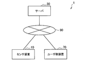
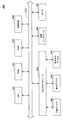
- FIG. 1 is an explanatory diagram for explaining a configuration example of the information processing system 1 according to the present embodiment.
- the information processing system 1 includes a sensor device 10, a server 30, and a user device 70, which are communicably connected to each other via a network 90.
- the sensor device 10, the server 30, and the user device 70 may be connected to the network 90 via a base station (not shown) or the like (for example, a base station of a mobile phone, an access point of a wireless LAN, etc.). That is, any communication method can be applied to the network 90 regardless of whether it is wired or wireless.
- a base station not shown
- any communication method can be applied to the network 90 regardless of whether it is wired or wireless.
- the sensor device 10 includes a sensor that can be attached to a part of the body of the instructor or the performer, an imaging device for imaging the instructor or the performer, a pressure sensor provided on a piano played by the instructor or the performer, Or it can be a sound collection device etc. which collects the sound of the piano concerned. As long as the sensor device 10 acquires a plurality of sensing data, the number and the type thereof are not particularly limited. The details of the sensor device 10 will be described later.
- the server 30 is configured by, for example, a computer.
- the server 30 is owned by a service provider who provides a service according to the present embodiment, and provides a service to each user or each third party.
- the server 30 collects sensing data relating to a performer or a trainee, analyzes the collected sensing data, and provides feedback to the trainee or the like. The details of the server 30 will be described later.
- the user-side device 70 is a device for notifying the trainee or the like of feedback information from the server 30, and visualizes feedback information during or after the performance of the trainee, force sense section, hearing, etc. Make it audible and notify.
- the user device 70 can be a tablet, a smartphone, a laptop PC (Personal Computer), a device such as a laptop PC, or the like.
- the user device 70 may be a wearable device that can be attached to a part of the body of the trainee.
- HMD Head Mounted Display
- ear device headphones
- anklet type bracelet type
- collar type eyewear type
- glove type glove type
- pad type batch type
- clothes type Wearable devices of various types such as can be adopted. The details of the user device 70 will be described later.
- the information processing system 1 according to the present embodiment is illustrated as including one sensor device 10 and the user device 70, but the present embodiment is limited to this. It is not a thing.
- the information processing system 1 according to the present embodiment may include a plurality of sensor devices 10 and the user device 70.
- the information processing system 1 according to the embodiment may include, for example, another communication device or the like such as a relay device when transmitting sensing data from the sensor device 10 to the server 30.
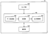
- FIG. 2 is a block diagram showing the configuration of the sensor device 10 according to the present embodiment.
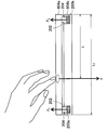
- FIG.3 and FIG.4 is explanatory drawing which shows an example of the sensor apparatus 10 which concerns on this embodiment.
- the sensor device 10 mainly includes a sensor unit 100, a main control unit 140, and a communication unit 160. Below, the detail of each function part of the sensor apparatus 10 is demonstrated.
- the sensor unit 100 acquires sensing data indicating the state of each motion element performed by each part of the body of the instructor or the performer, for example, by wearing the body of the instructor or the performer.
- the sensor unit 100 is realized by one or more sensor devices such as an acceleration sensor, an angular velocity sensor, a gyro sensor, a geomagnetic sensor, a position sensor, a vibration sensor, and a bending sensor.
- the sensor device as described above detects a change in acceleration or angular velocity given by a moving element, and generates a plurality of sensing data indicating the detected change.
- a plurality of sensing data obtained by the sensor unit 100 is output to the main control unit 140 described later.
- the sensor unit 100 may include a clock mechanism (not shown) for grasping an accurate time, and may link the time when the sensing data is acquired to the sensing data.
- the bending sensor is, for example, a sensor using an element whose resistance value changes non-linearly according to the amount of bending when it is bent. It can be detected.
- the posture (inclination), movement speed, and joints of fingers and arms in a space can be obtained by attaching the above-described sensor device to each joint or the like of the user's arms, legs, and torso. Can be quantitatively detected.
- the sensor unit 100 may be an imaging device for imaging a trainee or a performer.
- the marker 192 shown as a circle in FIG. 3 made of an LED (Light Emitting Diode) or the like is attached to the joints or fingers of the leader etc. .
- the movement of the marker 192 is captured by the high-speed shooting camera (imaging device) 194 which is an example of the sensor unit 100, thereby quantitatively detecting the position and the movement of the joint of the instructor or the like. be able to.
- the movement of the eyeball of the person to be guided may be detected by the imaging device.
- the sensor unit 100 is a nuclear magnetic resonance sensor that detects the state in the oral cavity or trachea of the instructor or the performer, the movement of the lip or the tongue, etc. using nuclear magnetic resonance. It may be Specifically, the above-mentioned state, movement, and the like can be detected by the instructor or the like performing a performance in a magnetic resonance imaging apparatus (MRI: Magnetic Resonance Imaging).
- MRI Magnetic Resonance Imaging
- the embodiments of the present disclosure are applied to the playing methods of various wind instruments (flute, oboe, clarinet, trumpet, etc.), it is possible to detect lip and tongue movements that are otherwise difficult to detect. Therefore, the above-mentioned MRI becomes useful.
- the sensor unit 100 may be a position sensor that detects the up and down movement of the keyboard of the piano due to the movement element of the instructor or the performer. For example, by installing a position sensor under each keyboard, the vertical movement of each keyboard can be detected, and the movement of the finger moving the keyboard up and down can be detected.
- the sensor unit 100 may be a pressure sensor that detects the pressure applied to the keyboard of the piano by the exercise element of the instructor or the performer.
- the sensor unit 100 may be a pressure sensor 196 mounted on the surface of a white key 600 of a piano.
- the sensor unit 100 may be a pressure sensor (not shown) that detects which position on the white key 600 a finger of a person to be instructed or the like presses. Specifically, by installing a thin plate on which two pressure sensors are mounted on each keyboard, it is possible to estimate the keying position of the finger or the like of the trainee based on the sensing data from each pressure sensor.
- the sensor unit 100 may be a sound collection device that collects the sound from the piano played by the instructor or the performer.
- the sensor unit 100 may be a microphone 198 provided in the vicinity of the piano.
- the sensor unit 100 strikes the piano with various forces by a robot or the like, and detects the sound at that time through the microphone 198.
- the server 30, which will be described later, generates relationship information between the parameters and the sound by correlating the parameters (force and the like) relating to keying and the data of the collected sound using machine learning or the like. Then, by using the related information, it is related to key depression of the trainee based on the state (for example, sound, tone, volume, etc.) of the sound collected from the performance of the trainee etc. newly by the microphone 198. Parameters can be obtained.
- the sensor unit 100 includes biological information sensors such as an myoelectric sensor, a heart rate sensor, a pulse sensor, a blood flow sensor, a respiration sensor, an electroencephalogram sensor, a skin temperature sensor, and a skin conductivity sensor.
- the myoelectric sensor is a sensor that detects a weak electric field generated from muscle fibers that constitute a muscle. Specifically, as shown in FIG. 3, the myoelectric sensor is generated in muscle fibers when a muscle such as an arm is contracted by a plurality of electrodes 190 attached to the arm or the like of the performer or the instructionee, By measuring the myoelectric potential by the electrical signal transmitted to the body surface, it is possible to quantitatively detect the amount of muscle activity of the muscle.
- the heart rate sensor is a sensor that detects a heart beat that is a beat in the heart, and the heart rate sensor sends blood to the whole body through the artery by the beat (heart rate) in the heart to change the pressure on the inner wall of the artery. It is a sensor which detects a pulse which is a pulse of an artery which arises and appears on a body surface etc.
- the blood flow sensor is a sensor that emits infrared light to the body and detects the blood flow by reflection of the infrared light.
- the respiration sensor can be a respiration flow meter that detects changes in respiration volume.
- An electroencephalogram sensor is a sensor for detecting an electroencephalogram by extracting a periodic wave by attaching a plurality of electrodes to the scalp and removing noise from fluctuations in the potential difference between the measured electrodes.
- the skin temperature sensor is a sensor that detects the temperature of the performer or the guided person
- the skin conductivity sensor is a sensor that detects the skin electrical resistance of the performer or the guided person.
- the sensor unit 100 may include a position information sensor such as a GPS (Global Positioning System) receiver that acquires position information of the instructor or the performer.
- the sensor unit 100 may include various other sensors such as an atmospheric pressure sensor, a temperature sensor, and a humidity sensor in order to acquire environment information indicating the state of the environment where the instructor or the performer plays.
- the main control unit 140 is provided in the sensor device 10 and can control each block of the sensor device 10.
- the main control unit 140 is realized by hardware such as, for example, a central processing unit (CPU), a read only memory (ROM), and a random access memory (RAM). Further, the main control unit 140 can also function as a data acquisition unit 142, a processing unit 144, and an output control unit 152. The details of these functions of the main control unit 140 according to the present embodiment will be described below.
- the data acquisition unit 142 controls the sensor unit 100 to acquire sensing data output from the sensor unit 100, and outputs the acquired sensing data to a processing unit 144 described later.
- the data acquisition unit 142 may include a clock mechanism (not shown) for grasping the accurate time, and may output the sensing data to the processing unit 144 by associating the time when the sensing data is acquired.
- the processing unit 144 converts the sensing data output from the data acquisition unit 142 described above into a predetermined format that can be transmitted via the network 90 (for example, converts sensing data that is an analog signal into a digital signal); It outputs to the output control part 152 mentioned later.
- the output control unit 152 transmits sensing data of a predetermined format output from the processing unit 144 described above to the server 30 by controlling a communication unit 160 described later.
- the communication unit 160 is provided in the sensor device 10, and can transmit and receive information with an external device such as the server 30.
- the communication unit 160 can be said to be a communication interface having a function of transmitting and receiving data.
- the communication unit 160 is realized by communication devices such as a communication antenna, a transmission / reception circuit, and a port.
- the sensor device 10 is a wearable device of various types such as HMD type, ear device type, anklet type, bracelet type, collar type, eyewear type, pad type, batch type, belt type, clothes type, etc. Good. Specifically, these wearable devices can be provided on the finger or arm, legs, torso, head, toes, etc. of the instructor or the performer to obtain various sensing data. . Furthermore, the sensor device 10 may be a device such as an imaging device, a sound collection device, etc. which is installed around a trainee or a performer.
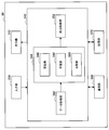
- FIG. 5 is a block diagram showing the configuration of the server 30 according to the present embodiment.
- FIG. 6 is an explanatory diagram for explaining the learning unit 348 according to the present embodiment.
- FIG. 7 is an explanatory diagram for explaining the calculation unit 346 according to the present embodiment.
- FIG. 8 is an explanatory diagram for explaining the comparison unit 350 according to the present embodiment.
- the server 30 is configured by, for example, a computer. As shown in FIG. 5, the server 30 mainly includes an input unit (attribute information acquisition unit) 300, an output unit 310, a main control unit 340, a communication unit 360, and a storage unit 370. The details of each functional unit of the server 30 will be described below.
- the input unit 300 receives input of data and commands to the server 30. More specifically, the input unit 300 is realized by a touch panel, a keyboard or the like, and can receive input of attribute information of a trainee or a player.
- the output unit 310 includes, for example, a display, a speaker, a video output terminal, an audio output terminal, and the like, and outputs various types of information as an image or audio.
- the main control unit 340 is provided in the server 30 and can control each block of the server 30.
- the main control unit 340 is realized by, for example, hardware such as a CPU, a ROM, and a RAM.
- the main control unit 340 can also function as a data acquisition unit (sensing data acquisition unit) 342, a processing unit 344, and an output control unit (notification unit) 352. The details of these functions of the main control unit 340 according to the present embodiment will be described below.
- the data acquisition unit 342 acquires the sensing data transmitted from the sensor device 10 described above, and outputs the acquired sensing data to the processing unit 344 described later.
- the processing unit 344 processes the sensing data output from the data acquisition unit 342 described above, calculates the degree of coordination indicating the coordination of the movement elements in the performance of the trainee from the sensing data, and based on the calculated degree of coordination Generate feedback information to give feedback to the leader. Furthermore, the processing unit 344 can create a DB 372 (see FIG. 6) including various information for calculating the above-described degree of cooperation and generating feedback information. Specifically, the processing unit 344 functions as a calculation unit 346, a learning unit 348, and a comparison unit 350 in order to realize the above-described functions. Details of these functions of the processing unit 344 according to the present embodiment will be described below.
- the calculation unit 346 applies a predetermined algorithm based on the sensing data transmitted from the sensor device 10 to calculate the degree of coordination indicating the coordination of the motion elements of the trainee related to the specific performance state. Do. Then, the calculation unit 346 outputs the calculation result to the comparison unit 350, the storage unit 370, and the like described later. More specifically, for example, the calculation unit 346 uses the DB 372 (stored in the storage unit 370 described later) obtained by machine learning by the learning unit 348 described later, and the target state of the performance set in advance. An appropriate algorithm is selected in accordance with (a target performance state) (for example, a player wants to play quickly), and a coordination degree indicating coordination of motion elements related to the target state is calculated.
- a target performance state for example, a player wants to play quickly
- a predetermined performance (music, phrase, etc.) is sent to a large number of players (for example, about 100 performers). Scales, arpeggios, chords, etc.) are performed, and a large number of sensing data relating to a large number of motion elements are collected from the performer using the above-described sensor device 10.
- the sensor device 10 collects sensing data on the movement of each finger of the player.
- the server 30 collects information on the state (performance state) about the performance of each performer.
- information on the performance status includes performance speed, accuracy of performance, volume of sound produced by performance, tone of sound, timbre, volume difference and time difference between single tones in chords, and each sound parameter Information, such as the difference between the maximum value and the minimum value, and the granularity of each sound parameter.
- information on the performance state can be collected by collecting sound with a microphone 198 provided in the vicinity of the performer and analyzing the sound data obtained by collecting the sound.
- attribute information (sex, age, height, weight, muscle strength, palm size, years of experience of piano performance, etc.) of each performer is acquired and input to the learning unit 348 of the processing unit 344. You may
- the sensing data acquired as described above, the information on the performance state, and the like are input to the learning unit 348 included in the processing unit 344 to cause the learning unit 348 to perform machine learning.
- the processing unit 344 is provided with a supervised learning unit (learning unit) 348 such as a support vector regression or a deep neural network.
- learning unit supervised learning unit
- the sensing data 500 and the performance state 502 acquired from the sensor device 10 are input to the learning unit 348 as an input signal and a teacher signal (label), respectively, and the learning unit 348 follows a predetermined rule. Machine learning is performed on the relationship between these pieces of information.
- the input signal and the teacher signal to be input do not have a one-to-one relationship as shown in FIG. 6, but a plurality of input signals (sensing data 500) and one teacher signal (playing state 502)
- a plurality of input signals and a plurality of teacher signals may be linked and input.
- information on the playing state which is a teacher signal, may be input in advance as a cluster. That is, in the present embodiment, information groups of a plurality of performers having similar performance tendencies may be handled as data groups of the same cluster. For example, in the present embodiment, clustering can be performed based on the player's skill level or the like determined using the above-described attribute information. Such cluster division can be used when selecting information to be used in the comparison unit 350 described later, or when classifying the performances of the trainee.
- the learning unit 348 obtains, by performing multivariate analysis, information on the relationship between the coordination degree of various combinations of motion elements in each performer and the playing state.
- the degree of coordination of the movement elements can be obtained by calculating the similarity between the change patterns of the sensing data 500 of each movement element in the same player.
- the degree of coordination can be obtained by extracting change patterns in the time course of the sensing data 500 of each motion element in the same period, and calculating the degree of similarity between them.
- the degree of coordination can be obtained by normalizing and extracting the change pattern in the three-dimensional space of the sensing data 500 of each motion element with a predetermined norm, and calculating the degree of similarity between them.
- the learning unit 348 performs multivariate analysis such as multiple regression analysis on the relationship between the degree of coordination thus obtained and the performance state 502 to obtain a characteristic degree of coordination (feature amount in each performance state).
- a characteristic degree of coordination feature amount in each performance state.
- the database (DB) 372 is constructed by storing the relationship information and the like obtained by machine learning in the storage unit 370 by the learning unit 348.
- the learning unit 348 may perform machine learning using a semi-supervised learning device in order to omit labeling on part of the sensing data 500.
- the learning unit 348 constructs the DB 372 by classifying the non-labeled sensing data 500 determined to be similar as belonging to the same cluster as compared with the sensing data 500 to which the label has already been attached. be able to.
- the learning unit 348 may perform weak teacher learning, for example, by asking a question about the performance state of each performer, and using temporary information determined based on an answer to the question as a rough teacher signal.
- the learning unit 348 may perform unsupervised learning that automatically performs cluster extraction itself using a large amount of data. In this case, the learning unit 348 automatically generates information indicating a playing state, which is a cluster or a teacher signal.
- the calculation unit 346 determines the specific performance state from the sensing data of the trainee newly acquired from the sensor device 10 based on the DB 372 obtained by machine learning of the learning unit 348.
- the degree of coordination 504 of the exercise factor of the related leader can be calculated.
- the calculation unit 346 extracts from the DB 372 the feature amount of the specific playing state, that is, the degree of coordination 504 that is highly related to the specific playing state such as performing correctly or performing quickly.
- the degree of coordination 504 of the predetermined motion element (the degree of coordination 504 regarding the same motion element as the extracted feature amount) is calculated from the newly obtained sensing data 500 of the trainee.
- the degree of cooperation calculated by the calculation unit 346 is not limited to one, and a plurality of degrees of cooperation 504 may be calculated.
- the calculating unit 346 outputs the calculated degree of coordination 504 to the comparing unit 350 described later.
- the comparison unit 350 selects a feature amount (coordination degree 504) (roll model) of a predetermined performance state (excellent performance of a skilled person) serving as an example of the instructor from the DB 372 Then, the degree of coordination 504 calculated by the calculation unit 346 is compared.
- the comparing unit 350 may calculate, for example, the difference (deviation) between the role model and the calculated degree of cooperation 504, or may calculate the degree of matching of these.
- the comparison unit 350 may extract information (such as the location of the body and the amount of movement) of the movement element necessary to make the calculated difference zero.
- the comparison part 350 produces
- the comparison unit 350 is a representative coordination degree 504 (coordination degree obtained from an excellent performance of a skilled person) which serves as a model of the instructor in a predetermined performance state such as accurate performance or quick performance from the DB 372 504) is selected as a role model, and the selected role model is compared with the degree of coordination 504 of the lead person.
- the comparison unit 350 calculates the difference from the coordination degree 504 of the corresponding trainee, and the representative coordination degree 504 having a large difference is The player's performance may be selected as a role model to be compared as having a degree of coordination 504 that needs to be corrected to approach the expert's good performance.
- the comparison unit 350 is more effective if the degree of coordination 504 most relevant to the given performance state is improved because the performance of the trainee approaches the superior performance of the expert. It may be selected as the degree of coordination 504 (role model).
- the comparison unit 350 may select the role model according to the attribute information (sex, age, physique, muscle strength, flexibility, agility, etc.) of the trainee. By making such a selection, it is possible to perform tailor-made feedback according to the attribute etc. of the trainee. For example, the comparison unit 350 selects, as a role model, the degree of coordination 504 of the expert having an attribute close to the attribute according to the attribute of the person to be led.
- the comparison unit 350 inverts the degree of coordination 504 of one skilled finger (for example, the dominant hand) when the proficiency levels of the left and right fingers of the person being guided differ. It may be selected as a role model of the coordination degree 504 of the other finger. In addition, when comparing the past and the present of the performer, the comparison unit 350 may select the past coordination degree 504 of the performer as a role model.
- the output control unit 352 transmits the feedback information 506 output from the processing unit 344 to the user device 70 by controlling a communication unit 360 described later. That is, the output control unit 352 can control feedback in the user device 70. Further, the output control unit 352 is not limited to transmitting all of the output feedback information 506 output from the processing unit 344 to the user device 70. For example, the output control unit 352 may select the feedback information 506 based on the attribute information of the trainee and the like, and may transmit the selected feedback information 506 to the user device 70. In detail, if there is a large amount of information to be fed back to the leader, the leader may be confused and on the contrary may become an obstacle to learning skills. Therefore, confusion of the trainee can be avoided by limiting the amount of information to be fed back according to the attribute of the trainee in the output control unit 352.
- the output control unit 352 may perform the selection of the feedback information 506 to be transmitted to the user device 70 based on the setting in advance.
- the output control will be described by taking, as an example, a case where the trainee intends to improve both the performance speed and the keystroke strength using the information processing system 1 according to the present embodiment. It will be described that the unit 352 selects the feedback information 506 based on the prior setting. In such a case, if the feedback information 506 for improvement (improvement) of "performance speed" and the feedback information 506 for improvement (improvement of "strength of keystroke") are fed back, the leader can be There is a risk of confusion.
- the present embodiment for example, it is previously set, by the instructor or the instructor, which one of the feedback information 506 of the playing speed and the keystroke strength should be preferentially fed back. Then, the output control unit 352 controls the user device 70 so as to preferentially feedback any feedback information 506 based on the setting. By doing this, it is possible to avoid confusion of the trainee. Further, in the present embodiment, the present invention is not limited to feedback of any one feedback information 506. For example, a plurality of feedback information 506 may be sequentially fed back with a time difference. In such a case, the order of feedback and the time difference may be set in advance so as to be suitably fed back to the trainee.
- the output control unit 352 uses an algorithm obtained by learning by the learning unit 348 described above.
- the feedback information to be transmitted to the user device 70 may be selected.
- the learning unit 348 inputs the content and the amount of information of the feedback information 506 fed back to the instructor, and information on the improvement of the performance of the instructor. Then, the learning unit 348 in which the information is input learns in advance the feedback information 506 and the relation information indicating the relation between the information amount and the improvement effect.
- the output control unit 352 transmits feedback information 506 to the user device 70 based on the feedback information 506 and the amount of information estimated to have a higher improvement effect using the relationship information obtained by the learning unit 348.
- choose by appropriately controlling the feedback information 506 fed back in this manner, it is possible to more effectively acquire and improve the performance of the trainee.
- the present embodiment not only the content and the information amount of the feedback information 506 but also the timing of feedback and the form of feedback at the time of feedback (display, voice, force sense, etc.) You may select based on the acquired information.
- the output control unit 352 may select the form of feedback (display, voice, force sense, etc.) based on the feedback information 506, the attribute information of the trainee, etc., and the information of the selected form of feedback May be transmitted to the user device 70.
- the output control unit 352 uses the operation of the expert serving as a model of the trainee as feedback information.
- the form of the feedback by the force sense mechanism 710 (see FIG. 9) that applies and transmits a force to a part (joint etc.) of Further, in the same case, the output control unit 352 selects the form of feedback by the display unit 714 (see FIG.
- the trainee or the like may set in advance in accordance with his / her preference or the like.
- the communication unit 360 is provided in the server 30, and can transmit and receive information with an external device such as the sensor device 10 or the user device 70.
- the communication unit 360 is realized by a communication device such as a communication antenna, a transmission / reception circuit, or a port.
- the storage unit 370 is provided in the server 30, and stores programs, information, and the like for the main control unit 340 described above to execute various processes, and information obtained by the processes.
- the storage unit 370 is realized by, for example, a magnetic recording medium such as a hard disk (HD) or a non-volatile memory such as a flash memory.
- the storage unit 370 can store the above-described DB 372.
- FIG. 9 is a block diagram showing the configuration of the user device 70 according to the present embodiment.
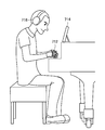
- FIG. 10 is an explanatory diagram for explaining an example of the user device 70 according to the present embodiment.
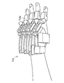
- FIG. 11 is an explanatory view for explaining an exoskeleton robot (wearable device) 712 according to the present embodiment.
- the user device 70 can be a device such as a tablet, laptop PC, laptop PC, wearable device, and the like. Further, as shown in FIG. 9, the user-side device 70 includes a force sense mechanism 710, a display unit 714, an audio output unit (audio output device) 716, a main control unit 740, a communication unit 760, and a storage unit. 770 mainly. The details of each functional unit of the user device 70 will be described below.
- the force sense mechanism 710 is a device that transmits a force sense such as applying a force to a part (a joint or the like) of the body of the trainee based on the feedback information 506 transmitted from the server 30.
- the force sense mechanism 710 is a glove-type wearable device (wearable device) 712 worn on the hand of the leader, as shown in FIG.
- the glove-type wearable device 712 is called a finger exoskeleton robot, and as shown in FIG. 11, a mechanism including a plurality of exoskeleton members 712a, and an actuator (electric actuator for moving the respective exoskeleton members 712a , Pneumatic actuator etc.) (not shown).
- the glove-type wearable device 712 applies a force to the finger or joint of the trainee by operating the exoskeleton member 712a by the above-described actuator, and, for example, the excessive or insufficient force in the extension / flexion direction of the joint Make the instructor feel the force.
- the above-described sensor device 10 may be attached to the force sense mechanism 710, and in this case, the force sense mechanism 710 obtains the target value of the sensor device 10, A force or stimulus may be applied to a part of the body of the trainee.
- the wearable device 712 is not limited to the glove type as shown in FIG. 11, but may be, for example, an arm cover type wearable device attached to the arm of the person being coached .
- the force sense mechanism 710 is not limited to the glove type wearable device 712 as described above, and, for example, a vibration device for giving a vibration to a part of the body of the coach, muscle
- the stimulation device may be an electric muscle stimulation that stimulates the skin. That is, in the present embodiment, the haptic mechanism 710 can sense feedback (biofeedback) of the feedback information 506 to the instructor by giving tactile stimulation to a part of the instructor's body. What is necessary.
- the force sense mechanism 710 can also be used when the trainee performs image training. For example, in the case where the motion of an expert who serves as an example of a subject is fed back by the haptic mechanism 710 as the feedback information 506, the subject may perform image training even without a piano or the like. it can. At this time, a performance sound corresponding to the feedback information 506 may be output to the trainee by an audio output unit 716 described later. In addition, the feedback by the force sense mechanism 710 may be reproduced at a slow speed, and the performance sound output by the audio output unit 716 may be output at a slow speed to further enhance the effect of the image training of the trainee.
- the display unit 714 is a device for displaying the feedback information 506 for the user such as the trainee, and outputs the feedback information 506 by an image or light toward the trainee, for example.
- the display unit 714 is realized by a display (image display device), a light emitting element (not shown), and the like as shown in FIG. Furthermore, the display unit 714 may be realized by a video output terminal or the like.
- the display unit 714 may display, for example, the difference between the role model and the degree of coordination 504 of the person being taught, which is included in the feedback information 506, changing the color according to the size of the difference. it can. Furthermore, in the case where the above difference is minute or the time during which the difference is occurring is a minute time, the display unit 714 makes it difficult for the trainee to perceive the difference. Information may be virtually enlarged and displayed. Specifically, the display unit 714 may visualize the difference by a predetermined scalar multiplication (enlargement in the spatial direction) or post it in slow motion (enlargement in the temporal direction). Furthermore, the display unit 714 may display the difference between the degree of coordination 504 of the performer in the past and the degree of coordination 504 of the present as described above, and may indicate the degree of learning of the performer.
- the display unit 714 may be a projection device capable of superimposing an object based on the feedback information 506 as augmented reality (AR) on a real space.
- a projection device can be, for example, a smart glass type wearable device (not shown) mounted in front of the eye of the trainee.
- the smart glass type wearable device is provided with a transmission type display, and the transmission type display is, for example, a virtual image optical system including a transparent light guide or the like using a half mirror or a transparent light guide plate. It is held in front of the leader's eye, and the object is displayed inside the virtual image optical system.
- the projection device may be an HMD attached to the head of the trainee.
- the voice output unit 716 is a device for voice output (alarm etc.) of the feedback information 506 to the user such as the trainee, for example, as shown in FIG. 10, a headphone speaker attached to the ear of the trainee 716 or a speaker (not shown) provided in the vicinity of the trainee.
- the audio output unit 716 may be realized by an audio output terminal or the like. For example, when a difference between the role model and the degree of coordination 504 of the instructor occurs, the audio output unit 716 performs feedback by outputting a specific sound to the instructor during performance.
- a unit corresponding to any suitable sensory modality of the force sense mechanism 710, the display unit 714, and the audio output unit 716 described above is selected and Give feedback to the leaders.
- feedback may be performed by the force sense mechanism 710, the display unit 714, and the audio output unit 716 at the same time, and is not particularly limited.
- the main control unit 740 is provided in the user device 70, and can control each block of the user device 70.
- the main control unit 740 is realized by, for example, hardware such as a CPU, a ROM, and a RAM.
- the communication unit 760 can transmit and receive information to and from an external device such as the server 30.
- the communication unit 760 is realized by a communication device such as a communication antenna, a transmission / reception circuit, or a port.
- the storage unit 770 is provided in the user device 70, and stores programs and the like for the main control unit 740 described above to execute various processes, and information obtained by the processes.
- the storage unit 770 is realized by, for example, a magnetic recording medium such as an HD, or a non-volatile memory such as a flash memory.
- the user device 70 may have an input unit (not shown).
- the input unit has a function of receiving input of data and a command to the user device 70. More specifically, the input unit is realized by a touch panel, a button, a switch, a key, a keyboard, a microphone, an image sensor, and the like.
- the function of the sensor unit 100 of the sensor device 10 and the force sense mechanism 710 of the user device 70 may be integrated into one wearable device.
- FIG. 12 is a sequence diagram for explaining an example of the information processing method according to the present embodiment.
- the information processing method according to the present embodiment includes a plurality of steps from step S100 to step S400. The details of each step included in the information processing method according to the present embodiment will be described below.
- Step S100 First, the sensor device 10 is mounted on a part of the body of the trainee in advance or installed around the trainee before the performance of the trainee. Then, when the trainee starts a predetermined performance (music, phrase, scale, arpeggio, chords, etc.), the sensor unit 100 of the sensor device 10 generates each movement element generated along with the movement of the trainee during the performance. Sensing changes in the acceleration, angular velocity, etc. of the object to acquire multiple sensing data. Furthermore, the sensor device 10 transmits the acquired sensing data to the server 30.
- a predetermined performance music, phrase, scale, arpeggio, chords, etc.
- Step S200 The server 30 acquires sensing data 500 from the sensor device 10.
- the server 30 calculates the degree of coordination 504 of the trainee related to the desired performance state by applying a predetermined algorithm based on the sensing data 500.
- Step S300 The server 30 compares the degree of coordination 504 obtained in step S200 described above with the role model selected from the DB 372, and generates feedback information 506 based on the comparison result. Then, the server 30 transmits the feedback information 506 to the user device 70 in order to provide feedback to the trainee.
- Step S400 The user device 70 provides feedback to the trainee based on the received feedback information 506.
- step S200 in FIG. 12 is a flowchart in step S200 according to the present embodiment.
- step S200 according to the present embodiment includes a plurality of steps from step S201 to step S205 in detail. The details of each step included in step S200 according to the present embodiment will be described below.
- Step S201 The server 30 acquires a plurality of sensing data 500 from the sensor device 10.
- Step S203 The server 30 selects from the DB 372 the degree of coordination 504 that is highly related to a specific performance state set in advance, such as performing correctly or performing fast, in other words, the feature value of the specific performance state.
- Step S205 The server 30 calculates the coordination degree 504 of the predetermined motion element corresponding to the feature amount selected in step S203 described above from the sensing data 500 of the trainee obtained in step S201.
- step S300 of FIG. 12 is described with reference to FIG.
- FIG. 14 is a flowchart in step S300 according to the present embodiment.
- step S300 according to this embodiment includes a plurality of steps from step S301 to step S309 in detail. The details of each step included in step S300 according to the present embodiment will be described below.
- Step S301 The server 30 acquires the degree of cooperation 504 of the trainee calculated in step S200 described above.
- Step S303 The server 30 selects, from the DB 372, a representative degree of coordination 504 (role model) as an example of the trainee in a predetermined performance state such as accurate performance or quick performance.
- Step S305 The server 30 calculates the difference between the role model selected in step S303 described above and the degree of cooperation 504 of the trainee acquired in step S301.
- Step S305 The server 30 generates the feedback information 506 based on the difference calculated in step S305 described above.
- Step S307 The server 30 selects a form of feedback (display, voice, force sense, etc.) based on the feedback information and the like generated in step S305 described above.
- information based on the degree of coordination of the plurality of motion elements in the performance performed by the plurality of parts of the user's body performing cooperatively or non-cooperatively An information processing apparatus, an information processing method, and a program that can be used to support learning of performance can be provided.
- the feedback information 506 is fed back by means according to a suitable sense modality, for example, the trainee can operate with himself or with another person (for example, a skilled person). Differences can easily be grasped.
- Example according to an embodiment of the present disclosure >> The details of the information processing method in the embodiment of the present disclosure have been described above. Next, an example of information processing according to an embodiment of the present disclosure will be more specifically described while showing a specific example. Note that the examples shown below are merely examples of the information processing according to the embodiment of the present disclosure, and the information processing according to the embodiment of the present disclosure is not limited to the following example.
- Example 1 First, with reference to FIG. 15 and FIG. 16, a first embodiment in which the above-described embodiment of the present disclosure is applied to a skill acquisition support system for playing the piano correctly will be described as the first embodiment.
- FIG.15 and FIG.16 is explanatory drawing for demonstrating the example of the feedback in a present Example.
- the skill acquisition support system can instruct the trainee how to move the fingers to play the piano correctly.
- a predetermined number of music pieces (parts of about 100 or so), or a part of a music piece, a phrase or the like (a scale, an arpeggio, a chord, etc.) may be played.
- the information processing system 1 which concerns on this embodiment senses the movement element in performance of the said performer by the sensor apparatus 10, and collects many sensing data 500.
- FIG. Furthermore, the collected sensing data 500 is labeled with the accuracy (performance state) 502 of the performance, and is input to the server 30 of the information processing system 1. Then, the server 30 performs multivariate analysis on the labeled sensing data 500 to find out the degree of coordination 504 of the movement element that is highly relevant to the accuracy of the performance.
- the accuracy 502 of the performance mentioned above is, for example, the degree of matching between the performance of each player and the score by sensing the performance sound by the microphone 198 etc and matching the score data separately input to the server 30 It can be calculated by taking it.
- the contents for determining the match include the consistency between the rhythm played by the player and the rhythm instructed by the score, and the volume of each sound played by the performer and each sound indicated by the score.
- the consistency with the volume can be mentioned.
- the accuracy 502 of the performance may be subjectively input by, for example, the user (for example, an index indicating the degree of accuracy of the performer determined by the user's subjectivity is input), and is particularly limited. It is not a thing.
- the server 30 selects from the DB 372 a representative degree of coordination 504 (role model) which is a model of the high performance of the performance, and is obtained from the selected role model and the above performance.
- the degree of coordination 504 calculated based on the sensing data 500 is compared.
- the server 30 generates feedback information 506 based on the comparison result and transmits the feedback information 506 to the user device 70.
- the role model is compared with the degree of coordination 504 of the subject, and it is analyzed that the cause of the largest deviation from the role model is the movement factor of the subject's right hand finger. Shall be determined by In that case, the server 30 may extract the movement direction and movement amount of the right finger of the trainee necessary to make the above-mentioned deviation zero.
- the user-side device 70 performs feedback for performing correctly to the trainee.
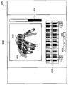
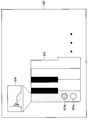
- the user-side device 70 displays a display screen 800 as shown in FIG. 15 toward the instructor during or after playing.
- the display screen 800 includes, on the right side thereof, a coincidence index bar 804 indicating the degree of coincidence between the role model and the degree of coordination 504 of the student. The higher the degree of coincidence, the longer the coincidence index bar 804 is displayed, so the trainee can instantly grasp the gap between himself and the roll model at first glance.
- the upper half of the center of the display screen 800 includes a finger display screen 802 for displaying the posture and operation of the finger.
- a finger display screen 802 for displaying the posture and operation of the finger.
- two image images schematically showing the right hand finger determined as the cause of the largest deviation from the roll model are superimposed and displayed. ing.
- an image 832 of a finger indicated by hatching indicates the posture and movement of the finger of the expert associated with the roll model
- the image 834 of the other finger is a finger of the person to be instructed.
- the trainee looks like Then, it is possible to grasp the gap between the operation of oneself and the expert. Therefore, in the present embodiment, the trainee can correct the shift of his / her right finger, bring his / her coordination degree 504 closer to the role model, and acquire the skill for accurate performance.
- the lower half of the center of the display screen 800 includes a keyboard display screen 836 schematically showing the keyboard.
- the upper keyboard may be a screen corresponding to the performance of the left finger
- the lower keyboard may be a screen corresponding to the performance of the right finger.
- the keyboard 838 displayed on the keyboard display screen 836 corresponds to the sound which the trainee could not correctly key.
- And may be displayed by changing colors with other keyboards.
- an alert display (not shown) is displayed on the display screen 800 in real time. The occurrence of an event may be presented to a trainee or the like by outputting a predetermined alert voice or the like.
- an event when an event occurs, it can be set in advance by the trainee or the like as to which the above alert is output.
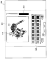
- the feedback in the present embodiment may be a display screen 806 as shown in FIG.
- the display screen 806 includes a finger display screen 808, a coincidence index bar 804, and a keyboard display screen 836, similarly to the display screen 800 of FIG.
- the coincidence index bar 804 and the keyboard display screen 836 of the display screen 806 are the same as the display screen 800 of FIG. 15, and thus the description thereof is omitted, and the finger display screen 808 will be described.
- the upper half of the center of the display screen 806 includes a finger display screen 808 for displaying the postures and actions of the fingers.
- a finger display screen 808 for displaying the postures and actions of the fingers.
- an image 840 schematically showing the finger of the trainee is displayed.
- the image 840 shows the posture and movement of the finger of the trainee.
- a plurality of vectors 810 are shown in a part of the image 840.
- Each vector 810 indicates the motion direction and the amount of movement (scalar) of the right finger of the trainee necessary to make the difference between the role model and the coordination degree 504 of the trainee zero.
- the finger display screen 806 since the deviation between the posture and the movement of the finger of the trainee's own finger and the posture and the movement of the finger of the expert concerning the roll model is illustrated as a vector 810, the trainee At a glance, it is possible to grasp the gap between the operation of oneself and the expert. Therefore, in the present embodiment, the trainee corrects the displacement of his / her right finger in accordance with the displayed vector 810, brings his / her coordination degree 504 closer to the roll model, and learns the skill for accurate performance. can do.
- Example 2 Next, as Example 2, Example 2 at the time of applying the embodiment of this indication mentioned above to the skill acquisition assistance system for playing a piano quickly is demonstrated with reference to FIG.17 and FIG.18.
- FIGS. 17 and 18 are explanatory diagrams for explaining an example of feedback in the present embodiment.
- the skill acquisition support system can instruct the trainee how to move fingers and how to use muscles to play the piano quickly.
- the information processing system 1 performs a large number of sensing operations.
- Data 500 is collected. Further, the collected sensing data is labeled by the speed of performance (state of performance) 502 and input to the server 30 of the information processing system 1. Then, the server 30 performs multivariate analysis on the labeled sensing data 500 to find out the degree of coordination 504 of the movement element that is highly related to the speed of the performance.
- the server 30 selects from the DB 372 a representative coordination degree 504 (role model) which is a model of a high-speed performance, and serves as an example of the instructor, and selects the selected roll model and the sensing obtained from the performance
- the degree of coordination 504 calculated based on the data 500 is compared.
- the server 30 generates feedback information 506 based on the comparison result and transmits the feedback information 506 to the user device 70.
- the role model is compared with the degree of coordination 504 of the instructor, and the cause of the largest deviation from the roll model is the tension of the muscle of both arms and fingers of the instructor. It is determined by analysis that it is the method of In that case, the server 30 may extract the amount of activity of the muscle of both arms and fingers of the trainee necessary to make the deviation zero.
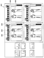
- the user-side device 70 performs feedback for the trainee to play quickly. Specifically, the user side device 70 displays a display screen 862 as shown in FIG. 17 toward the trainee.
- the display screen 862 is a screen for giving feedback on the muscle activity of the trainee at each time point.
- the cause of the largest deviation between the degree of coordination 504 of the trainee and the role model is how to tension the muscles of both arms and both fingers of the trainee Since it turns out that it is, it feeds back information on muscle activity to the trainee.
- the display screen 862 includes a plurality of windows 850 for feeding back information on the training subject's muscle activity at each time point during the performance of the training target.
- Each window 850 includes a finger display screen 864 and a match index bar 804, similarly to the display screen 800 of FIG.
- the finger display screen 864 includes an image 866 schematically showing the two left and right arms from the fingertip to the forearm.
- an area display 868 is illustrated in a part of each image 866. Specifically, the region display 868 at the position of the arm or finger muscle of the trainee necessary to make the difference between the role model and the coordination degree 504 of the trainee zero is zero the above-mentioned deviation.
- the color changes according to the amount of muscle activity required (in detail, the degree of tension).
- the display screen 862 since the difference in the position and activity amount of the muscle in which the difference in the muscle activity amount between the person in charge and the expert in the role model has occurred is shown by the color, At first glance, you can grasp the gap between the operation of yourself and the expert. Therefore, in the present embodiment, the trainee tensions or loosens tension on his / her arms and fingers according to the display screen 862, brings his / her coordination degree 504 closer to the roll model, and the skill for quick performance. You can learn In FIG. 17, the difference in the position of the muscle and the amount of activity where the difference in the amount of muscle activity between the instructor and the skilled person according to the role model occurs due to the difference in color is shown. Is not limited to this, and the above difference may be indicated by a difference in pattern, a symbol (marker) or the like.
- a display screen 870 as shown in FIG. 18 may be displayed toward the trainee.
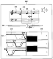
- the display screen 870 includes a keyboard display screen 872 schematically showing a keyboard, and each white key shown in the keyboard display screen 872 is provided with a speed display portion 876.
- the speed display unit 876 reproduces the movement of each keyboard by the performance of the instructor (or player) by animation.
- the color of the speed display unit 876 changes in accordance with the speed at which the trainee keyed the corresponding white key, and more specifically, the skilled person relating to the speed at which the trainee keyed and the roll model The color changes according to the difference in the keying speed.
- the speed display unit 876 may be displayed as a part of the keyboard, or may be displayed as the entire keyboard.
- a bar display 908 displayed on the keyboard may be used as the speed display portion 876. The height (or length) of the bar display 908 may change according to the speed of the keyboard, ie, the keying speed.
- the sensing data 500 itself may be displayed by a bar display like a bar display 908, a graph such as a pie graph (not shown), a numerical value, an animation, or the like.
- a bar display 908 or other display by changing the color, pattern, shape, etc. of the bar display 908 or other display, the finger of the student or the like has come away from the keyboard as to whether the student (or the player) has keyed ) May be shown.
- a mark (display) having a predetermined color is displayed at the timing when the trainee or the like performs keying, while a mark having a color other than the predetermined color is displayed at the timing when the key is released.
- the mark may not be displayed only at the moment of key depression or key release but may continue to be displayed until a predetermined time elapses after key depression or key release. The details of the bar display 908 and the like will be described later.
- time-series data of the finger speed when the trainee presses the corresponding keyboard so as to correspond to each white key on the display screen 870, on the upper side of each white key of the keyboard display screen 872, time-series data of the finger speed when the trainee presses the corresponding keyboard so as to correspond to each white key.
- a time series data display 874 shown is provided. Note that, in the time-series data display 874, time-series data of the difference between the speed at which the instructor keyed in and the speed of the expert may be displayed. Furthermore, these time-series data may include a marker (not shown) illustrated emphasizing the time when the speed becomes the fastest, the timing of lifting the finger from the keyboard, and the like.
- Embodiments of the present disclosure are not limited to the examples described above, and can be applied to various applications. The following briefly describes various applications of the embodiments of the present disclosure.
- the embodiment of the present disclosure can be applied when it is desired to learn a performance method such as a specific player A such as a famous player.
- the information processing system 1 collects sensing data 500 related to the performance of the player A.
- the information processing system 1 calculates the degree of coordination 504 of the movement element in the performance of the performer A based on the collected sensing data 500, and the degree of coordination 504 of the other performers. Compare with etc. By doing this, in the present application, the degree of coordination 504 that characterizes the performance of the player A, that is, the feature amount is extracted.
- the trainee can use the information processing system 1 according to the present embodiment when learning a performance method like the performer A. Also, in this application example, it is possible to reproduce performance similar to that of player A by using a humanoid robot, a robot arm, etc., by using the feature quantity that characterizes the performance of player A. Become.
- the information processing system 1 collects a plurality of sensing data 500 from the performance of a performer who is not converted into a database, and uses the collected plurality of sensing data 500 to perform another performer.
- the feature amount (second feature information) of the performance of the player is extracted.
- the information processing system 1 calculates and calculates the distance in the virtual space between the calculated feature amounts of other performers and the feature amounts of each performer put into a database. By comparing the distances, it is possible to determine (classify) which performer's performance on the database is close to that of other performers' performances.
- the information processing system 1 since it is possible to classify other performers from the feature amount of each performer on the database, it is possible to preliminarily diagnose, for example, the presence or absence of a disease such as dystonia. .
- the information processing system 1 includes a plurality of performers, a healthy skilled performer, a healthy general performer, a healthy novice, a dystonia patient, a non performer (a piano performer) (Classification), etc., and let each person play to collect sensing data 500 of each person.
- the information processing system 1 specifically, the learning unit 348) analyzes a plurality of sensing data 500 linked to each cluster, extracts a feature amount in each cluster, and extracts each extracted feature amount.
- a database is created as a feature that characterizes the performance of a person included in the cluster. Furthermore, the information processing system 1 collects a plurality of sensing data 500 from the performance of the performer who may suffer from dystonia, calculates the feature amount of the performer, and calculates the calculated feature amount on the database. It is possible to diagnose whether or not the player is affected by comparing with the feature value of each cluster.
- the effect of practice can also be evaluated by comparing the feature amounts of the past and the present of the trainee. Further, in the present application example, it is possible to study for obtaining clues for the player to escape from the slump by comparing with the feature amount of the performer in the best condition.
- the embodiment of the present disclosure can be applied when it is desired to learn a playing method for winning a contest.
- the information processing system 1 collects sensing data 500 related to the performance of the past contest winners.
- the information processing system 1 calculates the feature amount (the coordination degree of the movement element 504) in the performance of the winner based on the collected sensing data 500, and the feature of the non-winner Extract the winner's feature quantity by comparing with the quantity. Then, by selecting the extracted feature amount as a role model, the trainee can use the information processing system 1 according to the present embodiment when learning a performance method for winning a contest.
- the present invention is not limited to directly collecting the sensing data 500 of the winner's exercise factor, but may also collect the sound of the winner's performance at the contest.
- the information processing system 1 acquires relationship information indicating a relationship between a parameter (force or the like) of keystroke on the piano by a robot or the like and a sound at the time of the keystroke. Then, by analyzing the sound of the performance in the contest using the above-mentioned relationship information, it is possible to acquire the parameter regarding the keystroke of the winner as the sensing data 500.
- the embodiment of the present disclosure can be applied.
- the information processing system 1 acquires relationship information indicating the relationship between parameters (force etc.) of keystrokes on various pianos by a robot etc. and sounds at the time of the keystrokes. Then, the information processing system 1 analyzes the relationship information to identify the keying-related parameters necessary for producing sounds (sounds and tones) in a predetermined state in various pianos, and characterizes each piano. Extract feature quantities.
- the information processing system 1 can select a piano suitable for the performer by using the feature amount of the piano as described above and the feature amount of each performer described above in combination. .
- the information processing system 1 feeds the feature amount of each piano and the feature amount of each performer to the piano tuner so that the information processing system 1 matches the performer to the performer. Function as a support device for tuning the piano.
- position information and environment information obtained by the sensor unit 100 of the sensor device 10 may be used.
- the quality (sound, volume, etc.) of the sound changes in accordance with the environment (the structure of the performance hall, temperature, humidity, etc.) to be played. Therefore, in the present application example, for example, the information processing system 1 acquires information of the playing hall where the piano is played, based on the position information acquired by the position information sensor of the sensor device 10. At the same time, the information processing system 1 acquires information on the performance performed in the performance hall (sounds and the like) and environment information (temperature, pressure, humidity, and the like) of the environment in which the performance is performed.
- the information processing system 1 acquires and learns the feature amount (sound, volume, etc.) of the performance hall itself, and relationship information indicating the relationship between the environment information and the sound, using the acquired information. Furthermore, in the information processing system 1, the performer performs in the performance hall by utilizing the feature amount of the performance hall, the above-mentioned related information, and the above-mentioned feature amount of the piano and the performer. It is possible to select a suitable piano for playing the game, and a piano suitable for the weather (environment) on the day of the concert.
- the feature amount of the performer is described as the coordination degree 504 of the movement element characterizing the performance of the performer, but the embodiment of the present disclosure is limited thereto. It is not a thing. That is, in the present embodiment, the feature amount of the performer is not particularly limited as long as the information can characterize the performance of the performer. For example, even if it is the sensing data of the movement element itself Good.
- the embodiment of the present disclosure has been described as applied to a piano performance, but the present embodiment can also be applied to the performance of other musical instruments.
- the present embodiment is also applied to other keyboard instruments (eg, organ, harvaro, synthesizer, etc.), stringed instruments (eg, violin, cello, etc.), percussion (drums), wind instruments (flute, oboe, clarinet, etc.), etc. be able to.
- the sensor device 10 according to the present embodiment can detect the operation of the fingers, legs, neck, throat, etc. of the performer and the position of the string or hole to be pressed even in the performance of the various instruments described above. it can. More specifically, the movement of the tongue in the performer's mouth can be detected by the above-mentioned MRI.
- this embodiment is not limited to applying to the performance of a musical instrument, It is applicable also to singing and a whistling.
- the embodiments of the present disclosure can be applied to performances other than music.
- training for vocalization English vocalization, speech, etc.
- sports, rehabilitation rehabitation for improving physical paralysis, etc.
- games medical surgery training
- vehicles Training for driving cars, bicycles, wheelchairs, airplanes, etc.
- operation training for equipment construction machines, etc.
- skill training for creating art craft works (painting, calligraphy, origami, etc.), etc.
- the present embodiment is also applicable to image training.
- the trainee since the feedback information is fed back by means according to a suitable sense modality, for example, the trainee can operate with himself or with another person (for example, a skilled person). And the difference between their own past and present behavior. Therefore, in the present embodiment, it is possible to support the acquisition of the “knack” of the trainee, that is, the acquisition support of the performance. Further, in the present embodiment, not only comparison with other persons but also comparison between the present and the past of the person to be led can be made to easily know the degree of acquisition of the person to be led.
- FIG. 19 is an explanatory diagram showing an example of the hardware configuration of the information processing apparatus 900 according to the present embodiment.
- the information processing apparatus 900 illustrates an example of the hardware configuration of the server 30 described above.
- the information processing apparatus 900 includes, for example, a CPU 950, a ROM 952, a RAM 954, a recording medium 956, and an input / output interface 958.
- the information processing apparatus 900 further includes a force sense device 960, a display device 962, an audio output device 964, a communication interface 968, and a sensor 980. Further, the information processing apparatus 900 connects the respective constituent elements by, for example, a bus 970 as a data transmission path.
- the CPU 950 includes, for example, one or more processors including an arithmetic circuit such as a CPU, and various processing circuits, and functions as a main control unit 340 that controls the entire information processing apparatus 900.
- the ROM 952 stores programs used by the CPU 950, control data such as calculation parameters, and the like.
- the RAM 954 temporarily stores, for example, a program or the like executed by the CPU 950.
- the ROM 952 and the RAM 954 perform, for example, the function of the storage unit 370 described above in the information processing apparatus 900.
- the recording medium 956 functions as the storage unit 370 described above, and stores, for example, data related to the information processing method according to the present embodiment, various data such as various applications, and the like.
- the recording medium 956 may be removable from the information processing apparatus 900.
- the input / output interface 958 connects, for example, a force sense device 960, a display device 962, an audio output device 964 and the like.
- Examples of the input / output interface 958 include a Universal Serial Bus (USB) terminal, a Digital Visual Interface (DVI) terminal, a High-Definition Multimedia Interface (HDMI) (registered trademark) terminal, various processing circuits, and the like.
- USB Universal Serial Bus
- DVI Digital Visual Interface
- HDMI High-Definition Multimedia Interface
- the haptic device 960 functions as the haptic mechanism 710 described above
- the display device 962 functions as the display unit 714 described above
- the audio output device 964 functions as the audio output unit 716 described above.
- Examples of the display device 962 include a liquid crystal display and an organic electro-luminescence display.
- the input / output interface 958 can also be connected to an external device such as an external operation input device (for example, a keyboard or a mouse) of the information processing apparatus 900 or an external display device.
- an external operation input device for example, a keyboard or a mouse
- the communication interface 968 is a communication unit included in the information processing apparatus 900 functioning as the communication unit 360, and is a communication unit for performing wireless or wired communication with an external device via the network 90 (or directly). It functions as (illustration omitted).
- the communication interface 968 for example, a communication antenna and an RF (Radio Frequency) circuit (wireless communication), an IEEE 802.15.1 port and a transmitting / receiving circuit (wireless communication), an IEEE 802.11 port and a transmitting / receiving circuit (wireless communication) Or a LAN (Local Area Network) terminal and a transmission / reception circuit (wired communication).
- RF Radio Frequency
- each component described above may be configured using a general-purpose member, or may be configured by hardware specialized to the function of each component. Such configuration may be changed as appropriate depending on the level of technology to be implemented.
- the information processing apparatus 900 does not include the communication interface 968 when communicating with an external apparatus or the like via the connected external communication device, or when performing a process in a standalone manner. It is also good.
- the communication interface 968 may have a configuration capable of communicating with one or more external devices by a plurality of communication methods.
- the information processing apparatus may be applied to a system including a plurality of apparatuses on the premise of connection to a network (or communication between respective apparatuses) as in cloud computing, for example.
- the information processing apparatus according to the present embodiment described above can also be realized, for example, as an information processing system that performs processing according to the information processing method according to the present embodiment by a plurality of apparatuses.
- FIG. 20 is an explanatory diagram for explaining the configuration of the pressure sensor device 20 according to the first modification
- FIG. 21 is an explanatory diagram for explaining the operation of the pressure sensor device 20 according to the first modification
- FIG. 22 is an explanatory view for explaining an example of feedback of measurement results by the pressure sensor device 20 according to the first modification.
- the pressure sensor device 20 includes a pressure sensor 200 provided under the keyboard 604 (white key in FIG. 20) and an AD (Analog) that converts sensing data of the pressure sensor 200.
- AD Analog
- the pressure sensor device 20 includes a pressure sensor 200 provided under the keyboard 604 (white key in FIG. 20) and an AD (Analog) that converts sensing data of the pressure sensor 200.
- / Digital Analog
- an information processing apparatus 212 that processes the converted sensing data.
- the pressure sensor device 20 has a keyboard 604 including a pair of upper keyboard 604a and lower keyboard 604b created by a 3D printer or the like.
- the pair of upper keyboard 604a and lower keyboard 604b can be provided, for example, as many as the number of keyboards (white key 600 and black key) possessed by the piano.
- the upper keyboard 604a is a keyboard that is keyed by the finger of the instructor or the player, and moves in the vertical direction by the force applied by the keying.
- the lower keyboard 604b is fixedly provided to receive the upper keyboard 604a, and incorporates a pressure sensor 200 for detecting the movement of the upper keyboard 604a.
- two or more protrusions 202 are provided on the lower surface of the upper keyboard 604a along the longitudinal direction of the keyboard, and the protrusions 202 are formed on the upper surface of the lower keyboard 604b. It enters into the hole 204 provided so as to face each other. Furthermore, the pressure sensor 200 is provided on the bottom of the hole 204. Therefore, when the upper keyboard 604a is moved downward by keystroke, the protrusion 202 in the hole 204 presses the pressure sensor 200, whereby keystroke by the finger of the instructor or the performer can be detected. The sensing data of the pressure detected by the pressure sensor 200 is converted from an analog signal to a digital signal by the AD converter 210 and output to the information processing device 212.
- the position of the pressure sensor 200 provided is appropriately changed depending on whether the pair of upper keyboard 604 a and lower keyboard 604 b correspond to either the white key 600 or the black key. Good.
- two pressure sensors 200 a are provided, for example, along the longitudinal direction of one keyboard.
- the pressure sensor 200 located on the near side or the performer side is the pressure sensor 200a
- the pressure sensor 200 located behind the watched person or the performer is the pressure sensor 200b.
- the pressure by the pressure sensor 200a detects a F 1
- a pressure of the pressure sensor 200b detects the F 2.
- the magnitude F of the force by the keystroke of the trainee or the player can be detected as the resultant force of the pressures F 1 and F 2 detected by the two pressure sensors 200 a and 200 b. That is, the magnitude F of the force by the key-in of the trainee or the player can be detected as the following formula (1).
- the keyboard that is, the upper keyboard 604a is exercised like a seesaw by the keystrokes of the leader or the player. Therefore, when the length in the longitudinal direction of the keyboard is L 0 and the position of the keystrokes of the instructor or player is L with the back end of the keyboard as the start point, the following formula (2) is used for keying
- the position L can be calculated from the ratio of the pressures F 1 and F 2 detected by the two pressure sensors 200 a and 200 b.
- two pressure sensors 200 are provided for one keyboard along the longitudinal direction of the keyboard, but the present invention is not limited to this. Two pressure sensors 200 may be provided along the short direction. Further, in the present modification, a three-axis sensor may be used instead of the pressure sensor 200.
- the detection result by the pressure sensor 200 can be fed back to the user by using a display screen 820 as shown in FIG.
- the display screen 820 includes a keyboard display screen 822.
- the position at which the instructor keyed here, the position in the longitudinal direction of the keyboard
- a marker 824a white circle in FIG. 22
- the position at which the performer who acts as a model of the instructor has pressed may be displayed together with a marker 824 b (a circle indicated by hatching in FIG. 22).
- the user can clearly recognize the difference between the positions of the keystrokes of the instructor and the performer who is the model.
- it is not limited to showing the position where keying is performed in the form as shown in FIG.
- the positions where the instructor and player perform the keystrokes are superimposed on the piano keyboard in the real space where the trainee does the keystrokes using the augmented reality (AR) technology.
- AR augmented reality
- the form of display may be a marker 824 as shown in FIG. 22, an animation or the like.
- it can be embodied by a transmissive head mounted display (hereinafter, referred to as “HMD”) or the like mounted on the head or the like of the trainee.
- HMD transmissive head mounted display
- the HMD is not limited to the transmissive display, and may be a non-transmissive display.
- the HMD may have an imaging device such as a camera, and the positions where the keystrokes of the instructor and the performer are displayed may be displayed superimposed on the captured image of the piano keyboard in real space. Good.
- the HMD may superimpose and display the positions where the instructor and the performer have keyed on a virtual reality space on the keyboard.
- the display screen 820 may include a keying force display screen 826 for displaying, for each keyboard, a temporal change in the magnitude F of the force by the keystrokes of the instructor or the player. Also in this case, change over time in the magnitude F of the force F caused by the player's keystroke, which is an example of the instructor, by changing colors and line types (in FIG. 22, divided into solid lines and broken lines). You may display it. By displaying in this manner, the user can clearly recognize, for each keyboard, the difference in the force or change due to the keystrokes of the instructor and the performer as the model.
- the user or the performer's key depression that is, the movement of the keyboard by the key depression, the position of the key depression, the magnitude of the force by the key input, etc., in real time via the display screen 820 Can be fed back to
- FIG. 23 to FIG. FIG.23 and FIG.24 is explanatory drawing for demonstrating the structure of the photo reflector sensor apparatus 40 which concerns on this modification.
- FIG. 25 is an explanatory diagram for describing an operation of the photo reflector sensor 400 according to the present modification.
- FIG.26 and FIG.27 is explanatory drawing explaining the example of feedback of the measurement result by the photo reflector sensor apparatus 40 which concerns on this modification.
- FIG. 28 is a flowchart of an analysis process of measurement results by the photo reflector sensor device 40 according to the present modification
- FIG. 29 illustrates an analysis process of measurement results by the photo reflector sensor device 40 according to the present modification.
- FIG. 29 illustrates an analysis process of measurement results by the photo reflector sensor device 40 according to the present modification.
- the photo reflector sensor device 40 As shown in FIG. 23, the photo reflector sensor device 40 according to the present modification is arranged on the substrate 402 removably mounted under the keyboards of various pianos, and on the substrate 402 so as to correspond to the keyboard, And a plurality of photo reflector sensors 400 for detecting the movement of the keyboard to be keyed. Furthermore, the photo reflector sensor device 40 mainly includes an AD converter 410 that converts sensing data of the photo reflector sensor 400, and an information processing device 412 that processes the converted sensing data.
- the photo reflector sensor device 40 according to the present modification can be detachably provided under the keyboard of various pianos. Therefore, the photo reflector sensor device 40 may be attached to the piano at the time of manufacture or shipment of the piano, or may be retrofitted after shipment of the piano.
- each photo reflector sensor 400 is provided under each keyboard (white key 600 and black key 602).
- FIG. 24 shows 12 octaves of the keyboard (specifically, 7 white keys 600 and 5 black keys 602) corresponding to 12 octaves of keyboards.
- a photo reflector sensor 400 is provided. It is preferable that the photo reflector sensor 400 be provided on the lower side of the back side as viewed from the instructor or the player of each keyboard.
- each photo reflector sensor 400 is composed of a pair of light emitting elements 400 a for emitting light and light receiving elements 400 b for receiving light and light.
- the light emitting element 400a of the photo reflector sensor 400 is made of an LED (Light Emitting Diode) or the like, and can emit light having a predetermined wavelength.
- the light receiving element 400b of the photo reflector sensor 400 is formed of a photodiode or the like, and can generate a photocurrent (signal) according to the amount of light received. Therefore, part of the light emitted by the light emitting element 400a is reflected by the lower surface of the white key 600, reaches the light receiving element 400b, and can be detected by the light receiving element 400b.
- the white key 600 when the white key 600 is moved downward by being keyed by the instructor or the performer, the length of the path taken until the light emitted by the light emitting element 400a is detected by the light receiving element 400b is Since it changes, the light quantity of the light detected by the light receiving element 400b changes. Therefore, according to the photo reflector sensor 400, the light amount of the light detected by the light receiving element 400b changes according to the movement amount of the white key 600 in the vertical direction, so the signal (voltage value) from the photo reflector sensor 400 Thus, it is possible to detect the amount of movement of the white key 600.
- the display change of the movement amount of the keyboard can be acquired with high accuracy.
- the moment when the signal of the photo reflector sensor 400 exceeds a predetermined threshold is defined as the time when the keyboard starts moving (keying start time) (when the keyboard starts to descend). It can be regarded.
- the threshold can be appropriately set in consideration of noise (white noise and the like) and variations of the photo reflector sensor 400 itself. For example, a photo when the keyboard is stopped upward
- the standard deviation of the signal value from the reflector sensor 400 can be set to twice.
- the time-series change of the movement amount of the keyboard can be acquired with high accuracy, not only the keying start time as described above, but also the keying end time when keying is finished It is possible to acquire the keying time from the keying start time to the keying end time for each keyboard. Furthermore, in the present modification, it is possible to acquire, for each keyboard, temporal changes in the speed of keystroke (moving speed of the keyboard), acceleration (moving acceleration of the keyboard), and the amount of movement.
- event time and feature quantities can be detected from time-series data 842 of the keyboard movement amount obtained by the keystroke of the trainee or player, and can be fed back to the user.
- the event time includes a key entry start time, a key entry end time, a time when the keyboard is positioned at the lowermost position (descent end), a time when the keyboard is positioned at the uppermost position (descent end), It means, for example, the time when the speed of hitting is maximum (at the time of maximum speed), the time when the acceleration is at the maximum (when maximum acceleration), etc., and is not particularly limited.
- the event time to be detected and the feature amount are not particularly limited. More specifically, as shown in FIG. 26, by indicating the event time by the marker 844, it is possible to feed back to the user the timing at which the event occurred. At this time, the user may select which event time or feature amount to display.
- the time-series data 842b of the amount of movement of the keyboard by the keystroke of the performer who is the model of the instructor may be displayed together with the color or line type changed.
- the time-series data 842b of the keyboard movement amount by the performer's keystroke is shown by a line of a line type different from the time-series data 842a of the movement amount of the keyboard by the instructed person.
- the amount of movement of the keyboard by keystroke is not limited to being displayed as time-series data 842b of the movement amount, and the keyboard 904 shown on the keyboard display screen 872 (see FIG. 33) It may be shown by changing the color (see FIG. 33), or the gradation or pattern of the color. The details of such display of the movement amount will be described later.
- the data to be fed back to the user is not limited to the temporal change of the movement amount of the keyboard, but may be the temporal change of the movement speed, the movement acceleration or the like.
- the keyboard along with the above-mentioned change with time, the keying start time, the keying end time, and the time when the keyboard is positioned at the lowermost position (descent end time), the keyboard is positioned at the uppermost position.
- the time at which the keying speed is maximum at the maximum speed reached
- the maximum speed reaching time during the lowering or rising of the keyboard the maximum acceleration time, etc may be displayed.
- time-series data 842a of the amount of movement of the keyboard by the keystroke of the trainee and the time-series data 842b of the movement of the keyboard by the keystroke of the performer are displayed in superposition
- speed of keystroke moving speed of the keyboard
- acceleration moving acceleration of the keyboard
- the time-series data 842a of the amount of movement of the keyboard by the keystroke of the instructor, and the time-series data of the movement of the keyboard by the keystroke of the performer A display in another display mode may be performed in addition to the “phrase comparison mode” display displayed side by side as it is with 842 b.
- a "single tone comparison mode" display may be performed to compare temporal changes in the amount of movement of the keyboard one by one.
- time-series data for each key depression is performed in such a manner that the timing of key depression (key-input start time) in the time-series data 842a of the trainee and the timing of key depression in the player's time-series data 842b coincide It can display by cutting out and arranging 842a, and reconstructing time series data 842c.
- the analysis method for performing the said "one sound comparison mode" display is demonstrated with reference to FIG.28 and FIG.29.
- the analysis method according to the present modification includes a plurality of steps from step S501 to step S509. The details of each step included in the analysis method according to the present modification will be described below.
- Step S501 the photo reflector sensor device 40 acquires time-series data 842a of the amount of movement of the keyboard by the keystroke of the instructor.
- Step S503 the photo reflector sensor device 40 extracts the start time and the end time of each keystroke from the time-series data 842a obtained in step S501.
- the photo reflector sensor device 40 regards the moment when the signal of the photo reflector sensor 400 exceeds a predetermined threshold as the time when the keyboard starts moving (keying start time).
- the photo reflector sensor device 40 regards the moment when the signal of the photo reflector sensor 400 falls below a predetermined threshold as the time when the finger is released from the keyboard (key depression end time).
- the photo reflector sensor device 40 can extract the start time and the end time of each keystroke.
- the photo reflector sensor device 40 cuts out a section corresponding to each keystroke as time series section 842 d from time series data 842 a and holds it.
- Step S505 the photo reflector sensor device 40 starts the keying start time, the keying end time, the time when the keyboard is positioned at the lowermost position (descent end time), and the keyboard is the most from the respective time series sections 842d cut out in step S503 described above.
- Features such as time when positioned upward (end of rise), time when keying speed is maximum (at maximum speed reached), maximum speed arrival time during falling or rising of the keyboard, maximum acceleration arrival time, etc.
- the learning unit 348 described in the first embodiment extracts the time-dependent change of the movement amount of the keyboard that the instructor or the player has keyed, for each keying, and the extracted time series of each keying
- a feature amount (third feature information) is extracted from part of the change (time-series interval 842d).
- the photo reflector sensor device 40 visualizes the extracted feature amount by superimposing the marker 844 on the time series interval 842 d.
- Step S507 the photo reflector sensor device 40 re-arranges the cut out time series section 842 d in accordance with, for example, the time series data 842 b of the movement amount of the keyboard by the keystroke of the performer who is the model of the instructor. Do the configuration. Specifically, as shown in FIGS. 28 and 29, each time series interval 842 d is timed so that the key entry start time in each time series interval 842 d matches the key entry start time of the corresponding key entry in time series data 842 b. By shifting and arranging, the time-series data of the trainee is reconstructed as continuous data.
- the learning unit 348 described in the first embodiment re-enters a part of the extracted time-series change of each keystroke (time-series interval 842d) as continuous data according to a predetermined rule.
- time-series data 842 c the time-series data of the trainee obtained by the reconstruction.
- Step S509 the photo reflector sensor device 40 displays the time series data 842 c obtained in the above-mentioned step S 507 superimposed on the time series data 842 b of the movement amount of the keyboard by the keystroke of the performer who is the model of the instructor. Provide feedback to the user.
- FIG.30 and FIG.31 is explanatory drawing explaining the example of feedback of the measurement result by the photo reflector sensor apparatus 40 which concerns on this modification.
- the time-series data 842 in FIGS. 30 and 31 the movement amount of the keyboard when the keyboard moves downward is shown to be on the lower side in the drawings.
- time-series data of the movement amount of each keyboard so as to correspond to keyboard display screen 882 and the keyboard displayed on keyboard display screen 882.
- a time series data display 884 displaying 842 is shown.
- the time-series data display 884 includes time-series data 842a of the amount of movement of the keyboard by the keystroke of the instructor, and time-series data 842b of the movement of the keyboard by the keystroke of the performer who serves as an example of the instructor. Shall be displayed.
- a score display screen 886 is shown at the bottom of the display screen 880.
- the score display screen 886 has a frame 890, and a portion corresponding to a note in the frame 890 corresponds to time-series data 842 displayed by the time-series data display 884.
- a slide bar 888 is provided below the score display screen 886.
- the frame 890 of the score display screen 886 moves and is displayed on the time series data display 884.
- the range of time series data 842 can be changed. That is, in this modification, a part of the corresponding musical score can be displayed in synchronization with time-series data 842 fed back to the user.
- a voice corresponding to a part of the score may be output in synchronization with time-series data 842 to be fed back to the user.
- the frame 890 of the score display screen 886 is moved by the slide bar 888, and the present invention is not limited to changing the range of the time series data 842 displayed on the time series data display 884.
- the frame 890 of the score display screen 886 may be moved by moving the range of the time-series data 842 displayed in the time-series data display 884 using the slide bar 888.
- the present invention is not limited to the slide bar 888, and the score display screen 886 can be obtained by swiping, pinching in or pinching out the score display screen 886 or the time series data display 884.
- the range of time series data 842 to be displayed on the time series data display 884 may be changed.
- a display screen 880a as shown in FIG. 31 may be used.
- the size of the frame 890 of the score display screen 886 changes to change the range of the time series data 842 displayed on the time series data display 884.
- the user can select the time range of the time series data 842 to be displayed on the time series data display 884 by zooming in or out. By displaying in this way, the user can easily zoom in or zoom out and display time series data 842 in a desired range of a performance (music, a phrase, etc.).
- the time range of the time-series data 842 can be zoomed in, the time-series data 842 obtained when the trainee plays the chord of "Domiso" and the model become It is possible to visualize the deviation from the keying timing of the three tones in the time-series data 842 of the performer. And according to this modification, since such a minute gap can also be visualized, the user can easily recognize a gap that is difficult to recognize by hearing etc. It can promote the acquisition of performance.
- the size of the frame 890 of the score display screen 886 is changed by the slide bar 888 so that the range of the time series data 842 displayed on the time series data display 884 is changed. Absent.
- the size of the frame 890 of the score display screen 886 is changed by changing the size of the range of the time series data 842 displayed in the time series data display 884 using the slide bar 888. It is also good. That is, in the present modification, the score display screen 886 and the time-series data display 884 are displayed in synchronization with each other.
- the time-series data 842 of the other person used when comparing with the time-series data 842 of the trainee is a representative value such as an average value extracted from the time series data 842 of a plurality of skilled persons. It may be time series data 842 consisting of (collective knowledge) or time series data 842 of a specific expert. Furthermore, in the present variation, it is preferable to select time series data 842 to be compared to increase the level stepwise according to the level of skill of the trainee. In this way, the motivation of the trainee can be effectively stimulated, and the level of performance of the trainee can be improved more smoothly.
- time series data 842 it is preferable to tag the time series data 842 in advance by the size etc. of the player's hand of the time series data 842 to be compared.
- the trainee it is possible for the trainee to automatically select time-series data 842 to be compared according to the size of the hand.
- the size of the hand is not limited to the above, and attribute information such as the player's grip strength, hand shape, body size, proficiency, age, gender, etc.
- the time series data 842 may be tagged in advance. In this modification, by adding tags in this manner, time series data 842 for comparison can be selected in consideration of individual differences, and lessons tailored to individuals can be provided. .
- FIG. 32 is an explanatory diagram for describing a configuration of the muscle activity sensor device 60 according to the present modification.
- the muscle activity amount sensor device 60 is attached to the root of the subject's thumb, forefinger, middle finger, etc., for example, and detects and detects the amount of muscle activity of each finger of the subject. Feedback can be performed by vibration based on the amount of muscle activity.
- the muscle activity amount sensor device 60 according to the present modification includes a myoelectric potential sensor 610 that senses a muscle activity amount, and a vibrator 612 that performs feedback by tactile stimulation.
- the muscle activity sensor device 60 is a device in which the myoelectric potential sensor 610 and the vibrator 612 are integrated.
- the muscle activity sensor device 60 processes the converted sensing data, and the AD converter 620 that converts the sensing data of the myoelectric potential sensor 610, the microcontroller 630 that controls the vibrator 612, and the microcontroller 630. And an information processor 632 for controlling the
- the myoelectric potential sensor 610 is attached to a part of the skin 690 of the hand of the instructor, and can detect a change in myoelectric potential caused by the contraction activity of the muscle 692 (specifically, myofibers) . Further, the sensing data of the detected myoelectric potential is converted from an analog signal to a digital signal by the AD converter 620, and is output to the information processing device 632. Further, the information processing device 632 can control the vibrator 612 by comparing the sensing data 680 of the myoelectric potential with the predetermined threshold value 682 and outputting a signal to the microcontroller 630 based on the comparison result.
- the vibrator 612 is, for example, a vibrating device mounted on a smartphone or the like, and can change the amplitude and the vibration frequency of the vibration by control via the microcontroller 630. In this modification, it is preferable to configure so that the time taken for the vibrator 612 to vibrate after the myoelectric potential sensor 610 detects the amount of muscle activity is shorter, and in such a configuration The timing at which the muscle relaxes or tenses can be more accurately fed back in real time to the trainee.
- the information processing device 632 compares the sensing data 680 of the myoelectric potential with a predetermined threshold 682.
- the predetermined threshold 682 can be set, for example, as a percentage of the potential at the time of maximum muscle contraction of the corresponding muscle 692. Then, the information processing device 632 vibrates the vibrator 612 by outputting a signal to the microcontroller 630 when the sensing data 680 of the myoelectric potential exceeds the predetermined threshold 682 (or falls below the predetermined threshold).
- the vibration frequency of the vibrator 612 may be changed according to the magnitude of the myoelectric potential. For example, when the myoelectric potential exceeds a predetermined threshold value, the information processing device 632 determines that the corresponding muscle 692 is in a state of being tensioned more than necessary, and the higher frequency is applied to the instructor via the vibrator 612. Give vibration at. By doing this, the trainee can recognize that the muscle 692 is in the “strength” state, and can weaken the corresponding muscle.
- the vibration frequency at this time is preferably about 250 Hz, which is said to be the highest in sensitivity to human vibration.
- the information processing device 632 determines that the corresponding muscle 692 is in a more tense state, and the vibrator 612 is instructed to the trained person. Give vibration at low frequency through. By doing this, the trainee can make the muscle 692 more tense.
- the information processing device 632 controls the frequency, but in this modification, the magnitude of the amplitude may be controlled, or both may be controlled.
- the information processor 632 controls both the frequency and the amplitude to not only give feedback to the trainee whether control of the muscle 692 in the direction of weakness or tension is required. The degree of how much weakness should be reduced or how much tension should be given can also be fed back to the person to be led.
- the present modification even when the myoelectric potentials of the plurality of muscles 692 are detected, even if the feedback is given to the instructor based on the degree of coordination of the plurality of muscles 692 as in the embodiment described above. Good.
- this modification for example, by applying vibration to the thumb muscle 692 and the little finger muscle 692 in a situation where it is required to simultaneously tension (contract) the muscle 692 of the thumb and the muscle 692 for the little finger. Information can be fed back to the leadee, whether to tension any muscle 692 faster or stronger. In this way, the instructor can learn the coordinated action of the plurality of muscles 692 required at the time of playing the piano via the sense of touch.
- the myoelectric potential includes noise due to the influence of the impedance of the skin 690 of the person to be guided, fat, and the like. That is, even at rest of the muscle 692, individual differences exist in the magnitude of the myoelectric potential. So, in this modification, the myoelectric potential (background noise) at rest of the muscle 692 of the instructor and the myoelectric potential at the maximum muscle contraction are measured in advance. And in this modification, the difference between the myoelectric potential at rest and the myoelectric potential at the maximum muscle contraction is used to normalize the newly detected myoelectric potential to cope with individual differences in the myoelectric potential. It is possible to accurately detect the muscle potential generated by relaxation or tension of the muscle 692.
- the myoelectric potential itself is compared with a predetermined threshold value and fed back to the trainee by vibration, but this modification is not limited to this.
- the trainee You may give feedback. That is, in this modification, it is not limited to myoelectric potential, but muscle activity time etc. may be used.
- the present invention is not limited to the muscles 692 of fingers, and may be muscles of other parts on the body as long as it can detect myoelectric potential, and is not particularly limited.
- biological information other than myoelectric potential such as information on joint angles and angular velocity may be used.
- the muscle activity sensor device 60 may be used in combination with the force sense mechanism 710 described above.
- the muscle activity amount sensor device 60 may be attached to the finger tip of the trainee, and the above-described exoskeleton robot 712 may be attached to the finger joint.
- the muscle activity amount sensor device 60 feeds back to the subject the extent to which the corresponding muscle should be weakened or to which degree it should be tensioned.
- information such as in which direction and in which direction the finger is moved is fed back to the instructor by the exoskeleton robot 712.
- the instructor can perform multi-sensory information integrated learning (multi-modality learning) by the tactile sense at the fingertip and the force sense at the joint.
- multi-sensory information integrated learning multi-modality learning
- the trainee by combining it with visual feedback and auditory feedback, the trainee, for example, can be aware of differences in movement with himself or with others (e.g., skilled persons), his own past, etc. The difference between the current operation and the current can be grasped more easily. Therefore, in the present modification, it is possible to support the acquisition of the “knob” of the trainee, that is, the acquisition support of the performance.
- the force sense mechanism 710 may change the degree of the force applied to the joints of the fingers and the applied speed (for example, double speed, slow motion, etc.). At that time, the sound of the piano played by the trainee may be output. For example, by reproducing the speed of movement of the finger of the leader with the force sense mechanism 710 and forcefully applying it to the finger of the leader, the leader can use his / her finger at this time. It is possible to recognize the limit of the speed of movement. Also, for example, the force sense mechanism 710 may be induced to accelerate the movement of the finger of the coach by forcefully applying to the finger of the trainee while accelerating the movement stepwise. .
- FIGS. 33 and 34 are explanatory diagrams illustrating an example of feedback according to the third embodiment of the present disclosure.
- the user device 70 provides feedback to the trainee based on the received feedback information 506.
- the user-side device 70 displays a display screen 902 as shown in FIG. 33 toward the trainee during or after the performance.
- the display screen 902 includes, on the right side thereof, a keyboard display screen 872 schematically showing the keyboard, and on the left side, a time series of finger speeds when the trainee (or player) presses the corresponding keyboard. It includes a time series data display 874 indicating data.
- the keyboard display screen 872 and the time-series data display 874 are, for example, reproductions of the movement of each keyboard by the performance of the instructor or the like, and the range of the keyboard or performance to be changed or reproduced at the time of reproduction. And can be reproduced under the conditions desired by the user.
- each keyboard 904 included in the keyboard display screen 872 reproduces the movement of each keyboard by the performance of the instructor (or the player) by animation (for example, the reproduction animation speed is the speed desired by the user) Furthermore, the amount of movement of the keyboard which the trainee or the like has depressed during the performance can be indicated by the difference in color, gradation of color, or pattern.
- the color of the corresponding keyboard 904 is darkened as the keyboard is lowered close to the bottom, and the color of the corresponding keyboard 904 is lightened as the keyboard is raised.
- the user can not only reproduce the movement amount of the corresponding keyboard by the movement of each keyboard 904 included in the keyboard display screen 872 but also indicate the movement amount by the color of each keyboard 904, so the user can The movement amount of each keyboard can be easily grasped. Furthermore, in the present embodiment, based on the sensing data 500 acquired by another sensor device 10 (for example, the glove type sensor device 10 worn on the hand of the instructor, etc., the muscle activity amount sensor device 60, etc.) An animation in which the movement of a finger or the like is reproduced may be superimposed and displayed on each keyboard 904 or the like.
- another sensor device 10 for example, the glove type sensor device 10 worn on the hand of the instructor, etc., the muscle activity amount sensor device 60, etc.
- the performance sound acquired at the time of the performance may be reproduced in synchronization with the movement of each keyboard 904 which reproduces the movement of each keyboard by the performance of the instructor or the like by animation. Furthermore, the reproduction of the performance sound can be set to a speed desired by the user as well as the reproduction of the movement.
- the display screen 902 may display not only the amount of movement but also information on the movement speed.
- the triangular timing display 906a in FIG. 33 is displayed near the timing at which the falling speed (keying speed or movement speed) of the keyboard becomes maximum
- the shape of the timing display 906 is not limited to the triangle as shown in FIG.
- rectangular bar displays 908a and 908b in the figure are bars indicating the keyboard movement speed like a bar graph.
- a bar display 908 having a predetermined color or pattern extends downward, and when the keyboard rises, A bar display 908 having a predetermined color or pattern is shown extending upward.
- the trainee or the like intuitively moves the keyboard at the movement speed, that is, the timing at which the typing speed or the speed becomes maximum. Can be grasped.
- the display screen 910 also includes a keyboard display screen 872 schematically showing the keyboard on the right side, as described above, and on the left side, a finger when the instructor (or performer) presses the corresponding keyboard. And a time series data display 874 showing time series data of the speed of.
- an elastically deformable member made of urethane or the like and a position sensor are installed in the keyboard portion of the piano.
- the above-mentioned members are provided in contact with the bottom of the keyboard when the keyboard is moved downward by a predetermined distance (for example, 10 mm).
- the position sensor is provided on the bottom of each keyboard. Since the position sensor can measure the precise position, when the keyboard is deeply depressed, the bottom surface of the keyboard contacts the above-mentioned member, and the above-mentioned member is slightly deformed. The state where the keyboard sinks slightly deeper than the predetermined distance can be detected.
- each keyboard 904 included in the keyboard display screen 872 reproduces the motion of each keyboard by the performance of the instructor (or the performer) by animation, and the color and shade of color ( The difference in gradation, pattern, etc. can indicate the depth of the keyboard that the instructor (or the player) has keyed in playing.
- the striped pattern of the keyboard 904 indicates that the corresponding keyboard is sunk deeper than a predetermined distance, that is, it is unnecessarily pressing the keyboard. . Unnecessarily holding down the keyboard is generally said to be avoided as it reduces the sound, makes the tone harder, and also leads to the player using unnecessary energy.
- the color, pattern, and the like of the keyboard 904 are changed and displayed to indicate that the corresponding keyboard is sunk deeper than a predetermined distance, the trainee or the like The degree of pressing can be easily grasped, and as a result, the player is consciously played so as not to hold down an unnecessary keyboard which is generally considered to be avoided.
- the embodiment of the present disclosure described above may include, for example, a program for causing a computer to function as the information processing apparatus according to the present embodiment, and a non-temporary tangible medium in which the program is recorded. Also, the program may be distributed via a communication line (including wireless communication) such as the Internet.
- each step in the process of the embodiment of the present disclosure described above may not necessarily be processed in the order described.
- each step may be processed in an appropriate order.
- each step may be processed partially in parallel or individually instead of being processed chronologically.
- the processing method of each step may not necessarily be processed along the described method, for example, may be processed in another manner by another functional unit.
- a sensing data acquisition unit that acquires a plurality of sensing data from one or more sensors that sense the state of a plurality of motion elements in performance performed by a plurality of parts of the user's body operating;
- a calculation unit that calculates coordination information indicating movement coordination of the movement element from the plurality of acquired sensing data;
- a notification unit configured to notify feedback information to the user based on the calculated collaboration information;
- An information processing apparatus comprising: (2) The information processing apparatus according to (1), wherein the calculation unit calculates coordination information of the movement element having a relationship with a preset performance state.
- the calculation unit calculates the coordination information from the plurality of acquired sensing data, based on the relation information stored in advance in the storage unit.
- the information processing apparatus according to (2). (4) Machine learning of the relationship between the various performance states and the coordination information of the movement factor using the plurality of performance states and the plurality of sensing data corresponding to each of the plurality of performance states,
- the information processing apparatus further comprises a learning unit for acquiring the related information.
- the information processing apparatus performs multivariate analysis on the relationship information and extracts the cooperation information characterizing the state of each performance as first feature information.
- the learning unit extracts the collaboration information characterizing the performance of the user as second feature information based on the plurality of acquired sensing data.
- the learning unit classifies the state of the performance of the user based on the second feature information.
- the information processing apparatus selects a form of notification of the feedback information based on the generated feedback information.
- the notification unit notifies the user of the feedback information by controlling a display device to display a predetermined image.
- the notification unit notifies the user of the feedback information by displaying a position on the keyboard that the user has pressed.
- the notification unit notifies the user of the feedback information by displaying a temporal change of at least one of a movement amount, a movement speed, and a movement acceleration of the keyboard which the user has pressed. Or the information processing apparatus as described in (11).
- the information processing apparatus At the same time as the temporal change, at least one of the depression start time, the depression end time, the rise start time and the rise end time of the keyboard, and the maximum acceleration at the time of the depression or rise of the keyboard and the maximum acceleration attainment.
- the information processing apparatus wherein the feedback information is notified to the user by displaying.
- the information processing apparatus according to (12) or (13), wherein the notification unit displays a score corresponding to a keystroke of the user in synchronization with the temporal change.
- the notification unit is configured to notify the user of the feedback information by causing the user to perform tactile stimulation by controlling a wearable device attached to the body of the user. Information processing equipment.
- the notification unit notifies the user of the feedback information by causing the user to perform tactile stimulation based on a comparison result of a muscle activity amount of a part of the user's body and a threshold.
- the information processing apparatus according to (15).
- the apparatus further comprises an attribute information acquisition unit that acquires attribute information of the user, The comparison unit selects the first feature information based on the acquired attribute information.
- the information processing apparatus according to (8).
- the information processing apparatus wherein the state of the performance is indicated by at least one of a motion pattern, a motion speed, a motion accuracy, and a motion amount of the motion element of the user in the performance. (20) The information processing apparatus according to (2), wherein the performance state is indicated by a result state generated by the performance. (21)
- the plurality of sensing data is at least one of sensing data obtained from an acceleration sensor, a gyro sensor, an angular velocity sensor, a vibration sensor, a pressure sensor, a biological information sensor, a bending sensor, or a position sensor mounted on the user.
- the information processing apparatus according to any one of the above (1) to (20), including one.
- the plurality of sensing data may be obtained from an imaging device for imaging the user, a pressure sensor for sensing a pressure applied by a part of the user's body, or a nuclear magnetic resonance sensor for sensing nuclear magnetic resonance in the user
- the information processing apparatus according to any one of (1) to (21), including at least one of sensed sensing data.
- the plurality of sensing data includes at least one of sensing data obtained from a photo reflector sensor that senses the movement of a keyboard which is keyed by a part of the user's body.
- the information processing apparatus according to any one.
- the information processing apparatus according to any one of (1) to (24), wherein the plurality of sensing data include sensing data obtained from a sound collection device that senses a sound generated by the performance.
- the plurality of sensing data include sensing data obtained from a sound collection device that senses a sound generated by the performance.
- Information processing methods including: (27) A function of acquiring multiple sensing data from one or more sensors that sense the state of multiple motion elements in performance performed by multiple parts of the user's body operating; A function of calculating coordination information indicating movement coordination of the movement element from the plurality of acquired sensing data; A function of notifying the user of feedback information based on the calculated collaboration information; A program to make a
Landscapes
- Engineering & Computer Science (AREA)
- Physics & Mathematics (AREA)
- Theoretical Computer Science (AREA)
- General Physics & Mathematics (AREA)
- Multimedia (AREA)
- General Engineering & Computer Science (AREA)
- Educational Technology (AREA)
- Business, Economics & Management (AREA)
- Human Computer Interaction (AREA)
- Educational Administration (AREA)
- Health & Medical Sciences (AREA)
- General Health & Medical Sciences (AREA)
- Acoustics & Sound (AREA)
- Physical Education & Sports Medicine (AREA)
- Social Psychology (AREA)
- Psychiatry (AREA)
- Computer Vision & Pattern Recognition (AREA)
- User Interface Of Digital Computer (AREA)
- Auxiliary Devices For Music (AREA)
- Electrophonic Musical Instruments (AREA)
Abstract
【課題】ユーザの身体の複数の部分が協調的又は非協調的に動作することによって行われるパフォーマンスにおける複数の運動要素の協調度に基づく情報を当該ユーザにフィードバックする、パフォーマンスの習得支援に利用可能な情報処理装置、情報処理方法及びプログラムを提供する。 【解決手段】ユーザの身体の複数の部分が動作することによって行われるパフォーマンスにおける複数の運動要素の状態をセンシングする1つ又は複数のセンサから複数のセンシングデータを取得するセンシングデータ取得部と、取得した前記複数のセンシングデータから、前記運動要素の動作協調性を示す協調情報を算出する算出部と、算出した前記協調情報に基づいて、前記ユーザにフィードバック情報を通知する通知部と、を備える情報処理装置を提供する。
Description
本開示は、情報処理装置、情報処理方法及びプログラムに関する。
ピアノの演奏のようなパフォーマンスは、人物の身体の多数の部分(手指、肩、肘、筋等)が動作することによる多数の運動要素が、複雑に、且つ、協調的又は非協調的に組み合わされることにより、成り立っている。従って、上記パフォーマンスにおいては、各運動要素が好適な状態であってもすばらしいパフォーマンスを実現することができるとは限らず、多数の運動要素を好適に協調させたり、協調させなかったりすることにより、すばらしいパフォーマンスを実現することができる。
近年、容易に使用することができる各種センサが開発されたことにより、パフォーマンスにおける運動要素をセンシングして、その結果をフィードバック等することにより、パフォーマンスの習得支援に役立てる試みが行われるようになった。例えば、下記の特許文献1には、複数の人物の動作をセンシングして、得られたセンシングデータに基づいて、フィードバックを行う装置が開示されている。
先に説明にしたように、ピアノ演奏のようなパフォーマンスは、多数の運動要素が協調又は非協調することにより成り立っていることから、多数の運動要素を変数とするような多変数関数で表現される運動であると言える。従って、このような多変数関数で表現される運動においては、変数の数が多いことから、各運動要素の互いの協調性や関連性を解析することが難しいものであった。そのため、上記パフォーマンスにおける複数の運動要素の協調度を算出し、算出した協調度をフィードバックすることにより、パフォーマンスの習得支援につなげるという試みはなされてこなかった。
そこで、本開示では、ユーザの身体の複数の部分が協調的又は非協調的に動作することによって行われるパフォーマンスにおける複数の運動要素の協調度に基づく情報を当該ユーザにフィードバックする、パフォーマンスの習得支援に利用可能な新規且つ改良された情報処理装置、情報処理方法及びプログラムを提案する。
本開示によれば、ユーザの身体の複数の部分が動作することによって行われるパフォーマンスにおける複数の運動要素の状態をセンシングする1つ又は複数のセンサから複数のセンシングデータを取得するセンシングデータ取得部と、取得した前記複数のセンシングデータから、前記運動要素の動作協調性を示す協調情報を算出する算出部と、算出した前記協調情報に基づいて、前記ユーザにフィードバック情報を通知する通知部と、を備える情報処理装置が提供される。
また、本開示によれば、ユーザの身体の複数の部分が動作することによって行われるパフォーマンスにおける複数の運動要素の状態をセンシングする1つ又は複数のセンサから複数のセンシングデータを取得することと、取得した前記複数のセンシングデータから、前記運動要素の動作協調性を示す協調情報を算出することと、算出した前記協調情報に基づいて、前記ユーザにフィードバック情報を通知することと、を含む、情報処理方法が提供される。
さらに、本開示によれば、ユーザの身体の複数の部分が動作することによって行われるパフォーマンスにおける複数の運動要素の状態をセンシングする1つ又は複数のセンサから複数のセンシングデータを取得する機能と、取得した前記複数のセンシングデータから、前記運動要素の動作協調性を示す協調情報を算出する機能と、算出した前記協調情報に基づいて、前記ユーザにフィードバック情報を通知する機能と、をコンピュータに実現させるためのプログラムが提供される。
以上説明したように本開示によれば、ユーザの身体の複数の部分が協調的又は非協調的に動作することによって行われるパフォーマンスにおける複数の運動要素の協調度に基づく情報を当該ユーザにフィードバックする、パフォーマンスの習得支援に利用可能な情報処理装置、情報処理方法及びプログラムを提供することができる。
なお、上記の効果は必ずしも限定的なものではなく、上記の効果とともに、または上記の効果に代えて、本明細書に示されたいずれかの効果、または本明細書から把握され得る他の効果が奏されてもよい。
以下に添付図面を参照しながら、本開示の好適な実施の形態について詳細に説明する。なお、本明細書及び図面において、実質的に同一の機能構成を有する構成要素については、同一の符号を付することにより重複説明を省略する。
また、本明細書および図面において、実質的に同一または類似の機能構成を有する複数の構成要素を、同一の符号の後に異なる数字を付して区別する場合がある。ただし、実質的に同一または類似の機能構成を有する複数の構成要素の各々を特に区別する必要がない場合、同一符号のみを付する。また、異なる実施形態の類似する構成要素については、同一の符号の後に異なるアルファベットを付して区別する場合がある。ただし、類似する構成要素の各々を特に区別する必要がない場合、同一符号のみを付する。
なお、説明は以下の順序で行うものとする。
1.本開示に係る実施形態を創作するに至るまでの経緯
2.本開示の実施形態
2.1.本開示の実施形態に係る情報処理システム1の概要
2.2.本開示の実施形態に係るセンサ装置10の構成
2.3.本開示の実施形態に係るサーバ30の構成
2.4.本開示の実施形態に係るユーザ側装置70の構成
2.5.本開示の実施形態に係る情報処理方法
3.本開示の実施形態に係る実施例
3.1.実施例1
3.2.実施例2
3.3.その他の応用例
4.まとめ
5.ハードウェア構成について
6.第2の実施形態
6.1.変形例1
6.2.変形例2
6.3.変形例3
7.第3の実施形態
8.補足
1.本開示に係る実施形態を創作するに至るまでの経緯
2.本開示の実施形態
2.1.本開示の実施形態に係る情報処理システム1の概要
2.2.本開示の実施形態に係るセンサ装置10の構成
2.3.本開示の実施形態に係るサーバ30の構成
2.4.本開示の実施形態に係るユーザ側装置70の構成
2.5.本開示の実施形態に係る情報処理方法
3.本開示の実施形態に係る実施例
3.1.実施例1
3.2.実施例2
3.3.その他の応用例
4.まとめ
5.ハードウェア構成について
6.第2の実施形態
6.1.変形例1
6.2.変形例2
6.3.変形例3
7.第3の実施形態
8.補足
<<1.本開示に係る実施形態を創作するに至るまでの経緯>>
まず、本開示に係る実施形態を説明する前に、本発明者らが本開示に係る実施形態を創作するに至る背景について説明する。
まず、本開示に係る実施形態を説明する前に、本発明者らが本開示に係る実施形態を創作するに至る背景について説明する。
先に説明したように、ピアノの演奏のような楽器演奏等のパフォーマンスは、人物の身体の多数の部分(手指、肩、肘、筋等)が動作することによる多数の運動要素が、複雑に、且つ、協調的又は非協調的に組み合わされることにより、成り立っている。例えば、ピアノ演奏においては、手指と肘の関節とが協調的に動作したり、右手指と左手指とが非協調的に独立して動作したりする。従って、ピアノ演奏等においては、1つの手指の動作等といった単一の運動要素が好適に動作を行っている場合であっても、すばらしい演奏を実現することができるとは限らない。すなわち、手指と肘の関節とが協調的に動作したり、右手指と左手指とが非協調的に独立して動作したりというように、多数の運動要素を好適に協調させたり、協調させなかったりすることによって、すばらしい演奏を実現することができる。
ところで、ピアノ演奏のようなパフォーマンスは、多数の運動要素が協調又は非協調することにより成り立っていることから、多数の運動要素を変数とするような多変数関数で表現される運動であると言える。従って、このような多変数関数で表現される運動においては、変数の数が多いことから、各運動要素の互いの協調性や関連性を解析することが難しい。そのため、ピアノ演奏等に対しては、1つ又は数個の運動要素の組み合わせからなるような、すなわち、単一変数又は少ない変数で構成された変数関数で表現することが可能なスポーツの動作(野球バットによる打撃、テニスラケットによる打撃等)に対して行われる科学的、且つ、定量的な運動科学的解析がなされてはいなかった。
また、近年では、ピアノ演奏中の演奏者の各運動要素や筋肉活動を測定し、測定結果を当該演奏者にフィードバックすることも行われているが、そのほとんどが、単一の運動要素に関する測定値をフィードバックするだけであった。すなわち、演奏者に、複数の運動要素の協調についての情報がフィードバックされていないことから、上述のようなフィードバックを利用しても、演奏者は、どのように自身の身体の複数の部分をどのように協調的又は非協調的に動作させればよいのかを知得することが難しかった。このため、このような複数の運動要素の協調的又は非協調的な動作は、ピアノ演奏の「コツ」の1つであると考えられ、演奏者自身によって独自に試行錯誤する中で体得されるものであると考えられていた。
なお、ここで複数の運動要素の協調又は非協調とは、1つの運動要素(手指、肩、肘、筋等)の挙動(移動量、速度、移動方向、活動量等、又はこれらの変化)に対して、他の運動要素がどれだけ従属的に又は非従属的に挙動しているかを意味するものとする。より具体的には、複数の運動要素の動作協調性の度合いを示す協調度(協調情報)は、複数の身体の部位に跨る関節や筋間をどの程度強く協調させているか、もしくは、協調を弱めて独立に動作させているかを示す指標である。なお、本開示の実施形態においては、協調度は、2つの運動要素の協調に限定されるものではなく、3つ以上の運動要素の協調であってもよい。このような協調度は、所定の条件(演奏、時間等)下における複数の運動要素の変化パターンをセンシングし、センシングした変化パターンの互いの類似度を算出することにより取得することができる。
さらに、ピアノの演奏法の指導は、上述したように運動科学的な解析が行われていないことから、科学的根拠に基づくものではなく、指導者が会得した経験則に基づき行われることが一般的である。さらに、このような指導法は、主観的又は感覚的なものであり、具体性に乏しいこともあいまって、指導者が被指導者に伝達することが難しく、被指導者が指導内容を理解して、且つ、実践することが難しい。
さらに、ピアノ演奏法の指導は、科学的、且つ、客観的な指導方法が確立されているとは言えないことから、改善できる点が多くある。例えば、演奏者の性別、年齢、身体のサイズ(手の大きさ、身長、骨格等)、筋力、演奏する音楽の種類等に応じて、それぞれ好適な演奏法が存在すると考えられる。従って、プロフェッショナルの演奏家だけでなく、ピアノに親しむ一般の人々であっても、それぞれに好適な演奏法を体得することができれば、身体の故障(例えば、腱鞘炎)や脳神経疾患(例えば、フォーカル・ジストニア(付随意で持続的な筋肉収縮を引き起こす神経疾患))を避け、「楽に」つまり「楽しく」演奏することができるようになると考え得られる。しかしながら、このような演奏者の属性等に応じた演奏法を指導する指導法は確立されておらず、場合によっては、演奏者にとって好適ではない指導法を受け続ける中で、身体的な不調がさらに悪化して、思うような音楽を奏でられないという苦痛を抱える演奏者も少なくない。
このような状況において、本発明者らは、ピアノ演奏法の指導を、運動科学的な解析に基づいて、科学的、且つ、客観的に行うことを可能にする手段について、鋭意検討を重ねていた。本発明者らは、検討を行う中で、多変数関数で表現される運動であっても、多変量解析や機械学習を利用することにより、運動技能の向上と関係の深い運動要素の協調又は非協調を抽出することができることを知得した。そこで、本発明者らは、上記知得を一着眼点にすることにより、演奏時の手指の多彩な動きのような多数の運動要素を同時にセンシングし、センシングデータに対して解析を行うことにより、演奏において重要となる運動要素の協調又は非協調を探し出すことができると考えた。さらに、本発明者らは、上述のように探し出した結果に基づく情報を演奏者にフィードバックすることにより、ピアノ演奏の向上に役立てることができると考え、本開示の実施形態を創作するに至った。
詳細には、以下に説明する本開示の実施形態においては、まず、ピアノ演奏時の手指や腕の関節や筋の挙動である複数の運動要素、又は、運動要素に起因する変化(圧力、音等)を1つ又は複数のセンサによってセンシングする。さらに、本実施形態においては、このように得られた複数のセンシングデータ(各運動要素の時系列データ等)に対して多変量解析を行う。そして、当該多変量解析によって、ピアノの演奏において重要となる運動要素の協調又は非協調(特徴的な運動要素の協調又は非協調)を、定量的な情報として抽出することができる。本実施形態においては、多数の演奏者に係るセンシングデータを収集し、収集したセンシングデータを機械学習することにより、演奏の状態(正確に演奏する等)と各運動要素の協調又は非協調との関係を科学的に一般化することが可能となる。加えて、本実施形態においては、収集したセンシングデータや演奏の状態を特徴づける運動要素の協調又は非協調(特徴量)をデータベース(DB)化することもできる。
そして、本実施形態においては、指導を受ける被指導者から上述と同様にセンシングデータを収集し、収集したセンシングデータの特徴量(運動要素の協調又は非協調の情報)と、被指導者の手本となるセンシングデータ(熟練者の優れた演奏から得られたセンシングデータ)の特徴量(運動要素の協調又は非協調の情報)(以下、ロールモデルと呼ぶ)とを比較し、比較結果に基づいて被指導者にフィードバックを行う。具体的には、本実施形態においては、被指導者の演奏が熟練者の優れた演奏に近づくために、修正する必要性が高い、又は修正の優先度が高いと考えられる運動要素に係る協調度についての比較を行い、ロールモデルとのズレ(差分)や修正すべき具体的な内容(身体の箇所や動作量等)を被指導者にフィードバックする。なお、修正する必要性や優先度は、演奏の状態(正確に演奏する等)との関係性や、ロールモデルとのズレの大きさ等によって判断することができる。また、本実施形態においては、被指導者の属性情報(性別、年齢等)等に応じて、ロールモデルを選択することができ、このような選択を行うことにより、被指導者の属性等に応じたテーラーメイドのフィードバックを行うことが可能となる。
また、本実施形態においては、好適な感覚モダリティに応じて選択された手段によって、被指導者にフィードバックを行う。具体的には、本実施形態においては、上述のズレを、色彩等を利用して可視化して表示することにより、被指導者にフィードバックすることができる。さらに、本実施形態においては、上記ズレが微小であったり、上記ズレが生じている時間が微小時間であったりした場合には、被指導者が当該ズレを知覚することが難しくなることから、上記ズレの情報を仮想的に拡大化してフィードバックしてもよい。より具体的には、本実施形態においては、上記ズレをスカラー倍して可視化したり(空間方向における拡大化)、スローモーションで掲示したり(時間方向における拡大化)する。
また、本実施形態においては、被指導者に装着されたウェアラブルデバイスを介して、上記ズレの情報を被測定者にバイオフィードバックすることもできる。具体的には、本実施形態においては、被指導者の手指等に装着されたウェアラブルデバイスによって手指の各関節に力を印加する(例えば、伸展・屈曲方向の力がロールモデルに比べてどれだけ過剰か又は不足か等に応じて力を印加する)ことで、力覚的にフィードバックを行うことができる。
以下、このような本開示の実施形態に係る装置構成及び情報処理方法を順次詳細に説明する。なお、以下の説明においては、本開示の実施形態をピアノの演奏法の指導(技能習得)に適用した場合について説明する。しかしながら、本開示の実施形態は、ピアノの演奏法の指導に適用することに限定されるものではなく、他の楽器の演奏法や、スポーツ、伝統工芸の技能習得、運動機能障害のリハビリ等に適用することも可能である。
また、以下の説明においては、特に断りが無い場合には、ユーザとは、ピアノの演奏法の指導を受ける被指導者、本実施形態に係るDBの構築にあたりセンシングデータが収集される演奏者、又は、本実施形態に係る情報処理システムを利用するオペレータのいずれかを意味するものとする。
また、以下の説明において、ピアノ演奏の状態とは、演奏における演奏者の演奏速度(テンポ、リズム)、演奏の正確性(リズム又は各音の音量の正確性)、演奏によって生じる音の音量(音波形のピーク)、音の響き(音波形の積分値)、音色(スペクトラム)、和音(複数音)における音同士の音量差や時間差(いわゆる、和音における「バランス」)、各音パラメータの最大値と最小値との差分(レンジ)、各音のパラメータの粒度(解像度)等を意味するものとする。さらに、ピアノ演奏の状態は、上述の複数のパラメータのうちトレードオフ関係にあるパラメータ(例えば、演奏の速度と正確性)が存在することから、このような場合を考慮して、各パラメータの比率であってもよい。また、当該演奏の状態とは、人による主観的な評価による評価指標(この演奏者は正確性が高い等)であってもよい。また、本開示の実施形態をピアノ演奏だけでなく他の動作に適用した場合には、パフォーマンスの状態とは、ユーザが行う運動要素の運動パターン、運動速度、運動正確性、運動量(運動パワー、力積、仕事量等)、パフォーマンスによって生じる結果の状態等であってもよい。
なお、以下の説明において、特徴量は、特にことわりが無い限りは、特徴的な運動要素の協調又は非協調だけでなく、例えば、演奏者等の打鍵により鍵盤が下がる際と上がる際における、打鍵の最大速度と最大速度に到達したタイミング(時点)、打鍵の最大加速度と最大加速度に到達したタイミング、鍵盤の移動開始のタイミング、鍵盤が底についたタイミング等も含まれるとする。また、以下の説明において、特徴量は、鍵盤が底から離れたタイミング、初期位置に戻ったタイミング、及び、これらのタイミングの差分時間も含むものとする。さらに、特徴量は、連続する2つの音が同時に鳴っていた時間(レガートの時間長)、演奏上同時に打鍵するべき複数鍵盤に対する打鍵したタイミングの差(時間差)、最大打鍵速度に到達したタイミングの差、最大打鍵速度の差又は比、最大加速度の差又は比、等を含むことができる。加えて、特徴量は、鍵盤が底面に着いた際の加速度、すなわち、鍵盤の衝突による衝撃の強さや鍵盤が最底部のフェルト部を押し潰していた時間等を含むことができ、さらには、鍵盤が動き始めた瞬間の加速度、すなわち、指先と鍵盤の衝突による衝撃の強さ等を含むことができる。
<<2.本開示の実施形態>>
<2.1.本開示の実施形態に係る情報処理システム1の概要>
まずは、本開示の実施形態に係る情報処理システム1の概要構成について、図1を参照して説明する。図1は、本実施形態に係る情報処理システム1の構成例を説明する説明図である。
<2.1.本開示の実施形態に係る情報処理システム1の概要>
まずは、本開示の実施形態に係る情報処理システム1の概要構成について、図1を参照して説明する。図1は、本実施形態に係る情報処理システム1の構成例を説明する説明図である。
図1に示すように、本実施形態に係る情報処理システム1は、センサ装置10、サーバ30及びユーザ側装置70を含み、これらは互いにネットワーク90を介して通信可能に接続される。例えば、センサ装置10、サーバ30及びユーザ側装置70は、図示しない基地局等(例えば、携帯電話機の基地局、無線LANのアクセスポイント等)を介してネットワーク90に接続されてもよい。すなわち、ネットワーク90で用いられる通信方式は、有線又は無線を問わず任意の方式を適用することができる。以下に、本実施形態に係る情報処理システム1に含まれる各装置の概要について説明する。
(センサ装置10)
センサ装置10は、被指導者又は演奏者の身体の一部に装着可能なセンサ、被指導者又は演奏者を撮像する撮像装置、被指導者又は演奏者が弾くピアノに設けられた圧力センサ、もしくは、当該ピアノの音を収音する収音装置等であることができる。センサ装置10は、複数のセンシングデータを取得するものであれば、数やその種類については特に限定されるものではない。なお、センサ装置10の詳細については後述する。
センサ装置10は、被指導者又は演奏者の身体の一部に装着可能なセンサ、被指導者又は演奏者を撮像する撮像装置、被指導者又は演奏者が弾くピアノに設けられた圧力センサ、もしくは、当該ピアノの音を収音する収音装置等であることができる。センサ装置10は、複数のセンシングデータを取得するものであれば、数やその種類については特に限定されるものではない。なお、センサ装置10の詳細については後述する。
(サーバ30)
サーバ30は、例えば、コンピュータ等により構成される。サーバ30は、例えば、本実施形態によってサービスを提供するサービス提供者が保有し、各ユーザ又は各第三者に対してサービスを提供する。具体的には、サーバ30は、例えば、演奏者又は被指導者に係るセンシングデータを収集し、収集したセンシングデータを解析し、被指導者等へフィードバックを行う。なお、サーバ30の詳細については後述する。
サーバ30は、例えば、コンピュータ等により構成される。サーバ30は、例えば、本実施形態によってサービスを提供するサービス提供者が保有し、各ユーザ又は各第三者に対してサービスを提供する。具体的には、サーバ30は、例えば、演奏者又は被指導者に係るセンシングデータを収集し、収集したセンシングデータを解析し、被指導者等へフィードバックを行う。なお、サーバ30の詳細については後述する。
(ユーザ側装置70)
ユーザ側装置70は、被指導者等に、サーバ30からのフィードバック情報を通知するための装置であり、フィードバック情報を被指導者の演奏中又は演奏後等に可視化、力覚課、聴覚化、可聴化して通知する。例えば、ユーザ側装置70は、タブレット、スマートフォン、ラップトップ型PC(Personal Computer)、ノート型PC等のデバイス等であることができる。さらに、ユーザ側装置70は、被指導者の身体の一部に装着可能なウェアラブルデバイスであってもよい。より具体的には、ウェアラブルデバイスとしては、HMD(Head Mounted Display)型、イヤーデバイス(ヘッドフォン)型、アンクレット型、腕輪型、首輪型、アイウェア型、グローブ型、パッド型、バッチ型、衣服型等の各種の方式のウェアラブルデバイスを採用することができる。なお、ユーザ側装置70の詳細については後述する。
ユーザ側装置70は、被指導者等に、サーバ30からのフィードバック情報を通知するための装置であり、フィードバック情報を被指導者の演奏中又は演奏後等に可視化、力覚課、聴覚化、可聴化して通知する。例えば、ユーザ側装置70は、タブレット、スマートフォン、ラップトップ型PC(Personal Computer)、ノート型PC等のデバイス等であることができる。さらに、ユーザ側装置70は、被指導者の身体の一部に装着可能なウェアラブルデバイスであってもよい。より具体的には、ウェアラブルデバイスとしては、HMD(Head Mounted Display)型、イヤーデバイス(ヘッドフォン)型、アンクレット型、腕輪型、首輪型、アイウェア型、グローブ型、パッド型、バッチ型、衣服型等の各種の方式のウェアラブルデバイスを採用することができる。なお、ユーザ側装置70の詳細については後述する。
なお、図1においては、本実施形態に係る情報処理システム1には、1つのセンサ装置10及びユーザ側装置70が含まれるものとして示されているが、本実施形態においてはこれに限定されるものではない。例えば、本実施形態に係る情報処理システム1は、複数のセンサ装置10及びユーザ側装置70を含んでもよい。さらに、実施形態に係る情報処理システム1は、例えば、センサ装置10からサーバ30へセンシングデータを送信する際の中継装置のような他の通信装置等を含んでいてもよい。
<2.2.本開示の実施形態に係るセンサ装置10の構成>
次に、本開示の実施形態に係るセンサ装置10の構成について、図2から図4を参照して説明する。図2は、本実施形態に係るセンサ装置10の構成を示すブロック図である。図3及び図4は、本実施形態に係るセンサ装置10の一例を示す説明図である。
次に、本開示の実施形態に係るセンサ装置10の構成について、図2から図4を参照して説明する。図2は、本実施形態に係るセンサ装置10の構成を示すブロック図である。図3及び図4は、本実施形態に係るセンサ装置10の一例を示す説明図である。
本実施形態に係るセンサ装置10は、図2に示すように、センサ部100と、主制御部140と、通信部160とを主に有する。以下に、センサ装置10の各機能部の詳細について説明する。
(センサ部100)
センサ部100は、例えば、被指導者又は演奏者の身体に装着することにより、演奏中の被指導者又は演奏者の身体の各部分が行う各運動要素の状態を示すセンシングデータを取得することができる。例えば、センサ部100は、加速度センサ、角速度センサ、ジャイロセンサ、地磁気センサ、位置センサ、振動センサ、曲げセンサ等の1つ又は複数のセンサデバイスにより実現される。上述のようなセンサデバイスは、運動要素によって与えられる加速度や角速度等の変化を検出し、検出された変化を示す複数のセンシングデータを生成する。さらに、センサ部100によって得られた複数のセンシングデータは、後述する主制御部140に出力される。また、センサ部100は、正確な時刻を把握する時計機構(図示省略)を内蔵し、センシングデータに、当該センシングデータを取得した時刻を紐づけてもよい。
センサ部100は、例えば、被指導者又は演奏者の身体に装着することにより、演奏中の被指導者又は演奏者の身体の各部分が行う各運動要素の状態を示すセンシングデータを取得することができる。例えば、センサ部100は、加速度センサ、角速度センサ、ジャイロセンサ、地磁気センサ、位置センサ、振動センサ、曲げセンサ等の1つ又は複数のセンサデバイスにより実現される。上述のようなセンサデバイスは、運動要素によって与えられる加速度や角速度等の変化を検出し、検出された変化を示す複数のセンシングデータを生成する。さらに、センサ部100によって得られた複数のセンシングデータは、後述する主制御部140に出力される。また、センサ部100は、正確な時刻を把握する時計機構(図示省略)を内蔵し、センシングデータに、当該センシングデータを取得した時刻を紐づけてもよい。
なお、ここで、曲げセンサとは、例えば、曲げると曲げ量に応じて非線形に抵抗値が変化する素子を利用したセンサであり、例えば、ユーザの関節に装着することで、関節の曲げ角度を検出することができる。本実施形態においては、ユーザの腕や脚、胴体等の各関節等に、上述のようなセンサデバイスを装着することにより、空間内での手指や腕の姿勢(傾き)や、移動速度、関節の曲げ角度等を定量的に検出することができる。
また、本実施形態においては、センサ部100は、被指導者又は演奏者を撮像する撮像装置であってもよい。具体的には、図3に示すように、被指導者等の関節や手指等にLED(Light Emitting Diode)等からなるマーカ192(図3においては、円形状で示されている)を装着する。そして、本実施形態においては、センサ部100の一例である高速撮影カメラ(撮像装置)194によってマーカ192の動きをキャプチャすることにより、被指導者等の関節の位置や動きを定量的に検出することができる。なお、本実施形態においては、被指導者等の眼球の動きを撮像装置によって検出してもよい。
また、本実施形態においては、センサ部100は、核磁気共鳴を利用して、被指導者又は演奏者の口腔内又は気管内の状態や、唇又は舌の動き等を検出する核磁気共鳴センサであってもよい。具体的には、被指導者等が磁気共鳴画像装置(MRI:Magnetic Resonance Imaging)内で演奏を実行することにより、上述の状態や動き等を検出することができる。特に、本開示の実施形態を各種の吹奏楽器(フルート、オーボエ、クラリネット、トランペット等)の演奏法に適用する場合には、他の方法では検出が難しい唇や舌の動きが検出することができることから、上記MRIは有用となる。
また、センサ部100は、被指導者又は演奏者の運動要素によるピアノの鍵盤の上下動を検出する位置センサであってもよい。例えば、各鍵盤の下に位置センサを設置することにより、各鍵盤の上下動を検出し、各鍵盤を上下動させる手指の動きを検出することができる。また、センサ部100は、被指導者又は演奏者の運動要素によってピアノの鍵盤に与えられる圧力を検出する圧力センサであってもよい。例えば、センサ部100は、図4に示すように、ピアノの白鍵600の表面に装着された圧力センサ196であってもよい。さらに、センサ部100は、被指導者等の手指が白鍵600上のどの位置を打鍵するかを検出する圧力センサ(図示省略)であってもよい。具体的には、各鍵盤上に圧力センサを2個装着した薄いプレートを設置することにより、各圧力センサからのセンシングデータによって被指導者等の手指の打鍵位置を推定することができる。
また、センサ部100は、被指導者又は演奏者によって演奏されるピアノからの音を収音する収音装置であってもよい。例えば、センサ部100は、図4に示すように、ピアノの近傍に設けられたマイクロフォン198であってもよい。詳細には、センサ部100は、ロボット等によって様々な力でピアノを打鍵し、その際の音を、上記マイクロフォン198を介して検出する。さらに、後述のサーバ30は、打鍵に関するパラメータ(力等)と収音した音のデータとを機械学習等を利用して関係付けることにより、上記パラメータと音との関係情報を生成する。そして、関係情報を利用することにより、新たに上記マイクロフォン198で被指導者等の演奏から収音した音の状態(例えば、響き、音色、音量等)に基づいて、被指導者等の打鍵に関するパラメータを取得することができる。
また、本実施形態においては、センサ部100は、筋電センサ、心拍センサ、脈拍センサ、血流センサ、呼吸センサ、脳波センサ、皮膚温度センサ、皮膚導電率センサ等の生体情報センサを含んでいてもよい。ここで、筋電センサとは、筋肉を構成する筋線維から発生する微弱な電場を検知するセンサである。詳細には、筋電センサは、図3に示すように、演奏者又は被指導者の腕等に装着された複数の電極190によって、腕等の筋が収縮する際に筋線維において発生し、身体表面に伝播する電気信号による筋電位を測定することにより、筋の筋活動量を定量的に検出することができる。
また、心拍センサは、心臓における拍動である心拍を検出センサであり、脈拍センサは、心臓における拍動(心拍)により、動脈を通じ全身に血液が送られることにより、動脈内壁に圧力の変化が生じ、体表面等に現れる動脈の拍動である脈拍を検出するセンサである。血流センサは、身体に赤外線を放射し、その赤外光の反射により血流量を検出するセンサである。さらに、呼吸センサは、呼吸量の変化を検出する呼吸流量計であることができる。脳波センサは、頭皮に複数の電極を装着し、測定した電極間の電位差の変動から雑音を除去することにより周期性のある波を抽出することにより脳波を検出するセンサである。皮膚温度センサは、演奏者又は被指導者の体温を検出するセンサであり、皮膚導電率センサは、演奏者又は被指導者の皮膚電気抵抗を検出するセンサである。
さらに、センサ部100は、被指導者又は演奏者の位置情報を取得するGPS(Global Positioning System)受信機等の位置情報センサを含んでいてもよい。また、センサ部100は、被指導者又は演奏者が演奏する環境の状態を示す環境情報を取得するために、気圧センサ、温度センサ、及び、湿度センサ等の他の各種センサを含んでもよい。
(主制御部140)
主制御部140は、センサ装置10内に設けられ、センサ装置10の各ブロックを制御することができる。当該主制御部140は、例えば、CPU(Central Processing Unit)、ROM(Read Only Memory)、RAM(Random Access Memory)等のハードウェアにより実現される。また、当該主制御部140は、データ取得部142、処理部144、及び出力制御部152として機能することもできる。以下に、本実施形態に係る主制御部140のこれら機能の詳細について説明する。
主制御部140は、センサ装置10内に設けられ、センサ装置10の各ブロックを制御することができる。当該主制御部140は、例えば、CPU(Central Processing Unit)、ROM(Read Only Memory)、RAM(Random Access Memory)等のハードウェアにより実現される。また、当該主制御部140は、データ取得部142、処理部144、及び出力制御部152として機能することもできる。以下に、本実施形態に係る主制御部140のこれら機能の詳細について説明する。
-データ取得部142-
データ取得部142は、センサ部100を制御して、センサ部100から出力されたセンシングデータを取得し、取得したセンシングデータを後述する処理部144へ出力する。また、データ取得部142は、正確な時刻を把握する時計機構(図示省略)を内蔵し、センシングデータに、当該センシングデータを取得した時刻を紐づけて処理部144へ出力してもよい。
データ取得部142は、センサ部100を制御して、センサ部100から出力されたセンシングデータを取得し、取得したセンシングデータを後述する処理部144へ出力する。また、データ取得部142は、正確な時刻を把握する時計機構(図示省略)を内蔵し、センシングデータに、当該センシングデータを取得した時刻を紐づけて処理部144へ出力してもよい。
-処理部144-
処理部144は、上述したデータ取得部142から出力されたセンシングデータを、ネットワーク90を介して送信可能な所定の形式に変換し(例えば、アナログ信号であるセンシングデータをデジタル信号に変換する)、後述する出力制御部152に出力する。
処理部144は、上述したデータ取得部142から出力されたセンシングデータを、ネットワーク90を介して送信可能な所定の形式に変換し(例えば、アナログ信号であるセンシングデータをデジタル信号に変換する)、後述する出力制御部152に出力する。
-出力制御部152-
出力制御部152は、上述した処理部144から出力された所定の形式のセンシングデータを、後述する通信部160を制御してサーバ30へ送信する。
出力制御部152は、上述した処理部144から出力された所定の形式のセンシングデータを、後述する通信部160を制御してサーバ30へ送信する。
(通信部160)
通信部160は、センサ装置10内に設けられ、サーバ30等の外部装置との間で情報の送受信を行うことができる。言い換えると、通信部160は、データの送受信を行う機能を有する通信インタフェースと言える。なお、通信部160は、通信アンテナ、送受信回路やポート等の通信デバイスにより実現される。
通信部160は、センサ装置10内に設けられ、サーバ30等の外部装置との間で情報の送受信を行うことができる。言い換えると、通信部160は、データの送受信を行う機能を有する通信インタフェースと言える。なお、通信部160は、通信アンテナ、送受信回路やポート等の通信デバイスにより実現される。
なお、センサ装置10は、HMD型、イヤーデバイス型、アンクレット型、腕輪型、首輪型、アイウェア型、パッド型、バッチ型、ベルト型、衣服型等の各種の方式のウェアラブルデバイスであってもよい。具体的には、これらウェアラブルデバイスは、様々なセンシングデータを取得するために、被指導者又は演奏者の手指、腕部、脚部、胴部、頭部、足先等に設けられることができる。さらに、センサ装置10は、撮像装置、収音装置等の被指導者又は演奏者の周囲に設置される装置であってもよい。
<2.3.本開示の実施形態に係るサーバ30の構成>
次に、本開示の実施形態に係るサーバ30の構成について、図5から図8を参照して説明する。図5は、本実施形態に係るサーバ30の構成を示すブロック図である。図6は、本実施形態に係る学習部348を説明するための説明図である。図7は、本実施形態に係る算出部346を説明するための説明図である。さらに、図8は、本実施形態に係る比較部350を説明するための説明図である。
次に、本開示の実施形態に係るサーバ30の構成について、図5から図8を参照して説明する。図5は、本実施形態に係るサーバ30の構成を示すブロック図である。図6は、本実施形態に係る学習部348を説明するための説明図である。図7は、本実施形態に係る算出部346を説明するための説明図である。さらに、図8は、本実施形態に係る比較部350を説明するための説明図である。
先に説明したように、サーバ30は、例えば、コンピュータ等により構成される。図5に示すように、サーバ30は、入力部(属性情報取得部)300と、出力部310と、主制御部340と、通信部360と、記憶部370とを主に有する。以下に、サーバ30の各機能部の詳細について説明する。
(入力部300)
入力部300は、サーバ30へのデータ、コマンドの入力を受け付ける。より具体的には、当該入力部300は、タッチパネル、キーボード等により実現され、被指導者又は演奏者の属性情報の入力を受けつけることができる。
入力部300は、サーバ30へのデータ、コマンドの入力を受け付ける。より具体的には、当該入力部300は、タッチパネル、キーボード等により実現され、被指導者又は演奏者の属性情報の入力を受けつけることができる。
(出力部310)
出力部310は、例えば、ディスプレイ、スピーカ、映像出力端子、音声出力端子等により構成され、画像又は音声等により各種の情報を出力する。
出力部310は、例えば、ディスプレイ、スピーカ、映像出力端子、音声出力端子等により構成され、画像又は音声等により各種の情報を出力する。
(主制御部340)
主制御部340は、サーバ30内に設けられ、サーバ30の各ブロックを制御することができる。当該主制御部340は、例えば、CPU、ROM、RAM等のハードウェアにより実現される。また、当該主制御部340は、データ取得部(センシングデータ取得部)342、処理部344及び出力制御部(通知部)352として機能することもできる。以下に、本実施形態に係る主制御部340のこれら機能の詳細について説明する。
主制御部340は、サーバ30内に設けられ、サーバ30の各ブロックを制御することができる。当該主制御部340は、例えば、CPU、ROM、RAM等のハードウェアにより実現される。また、当該主制御部340は、データ取得部(センシングデータ取得部)342、処理部344及び出力制御部(通知部)352として機能することもできる。以下に、本実施形態に係る主制御部340のこれら機能の詳細について説明する。
-データ取得部342-
データ取得部342は、上述したセンサ装置10から送信されたセンシングデータを取得し、取得したセンシングデータを後述する処理部344へ出力する。
データ取得部342は、上述したセンサ装置10から送信されたセンシングデータを取得し、取得したセンシングデータを後述する処理部344へ出力する。
-処理部344-
処理部344は、上述したデータ取得部342から出力されたセンシングデータを処理し、センシングデータから被指導者の演奏における運動要素の協調性を示す協調度を算出し、算出した協調度に基づき、被指導者へフィードバックするフィードバック情報を生成する。さらに、処理部344は、上述の協調度の算出やフィードバック情報を生成するための各種情報からなるDB372(図6参照)を作成することもできる。詳細には、処理部344は、上述したこれら機能を実現するために、算出部346、学習部348、比較部350として機能する。以下に、本実施形態に係る処理部344のこれら機能の詳細について説明する。
処理部344は、上述したデータ取得部342から出力されたセンシングデータを処理し、センシングデータから被指導者の演奏における運動要素の協調性を示す協調度を算出し、算出した協調度に基づき、被指導者へフィードバックするフィードバック情報を生成する。さらに、処理部344は、上述の協調度の算出やフィードバック情報を生成するための各種情報からなるDB372(図6参照)を作成することもできる。詳細には、処理部344は、上述したこれら機能を実現するために、算出部346、学習部348、比較部350として機能する。以下に、本実施形態に係る処理部344のこれら機能の詳細について説明する。
算出部346は、センサ装置10から送信されたセンシングデータに基づいて、所定のアルゴリズムを適用することにより、特定の演奏の状態と関係する被指導者の運動要素の協調性を示す協調度を算出する。そして、算出部346は、算出結果を後述する比較部350及び記憶部370等に出力する。より具体的には、例えば、算出部346は、後述する学習部348による機械学習によって得られたDB372(後述する記憶部370に格納される)を利用して、予め設定された演奏の目標状態(目標とするパフォーマンスの状態)(例えば、素早く演奏したい等)に応じて適切なアルゴリズムを選択し、目標状態と関係を持つ運動要素の協調性を示す協調度を算出する。
そこで、本実施形態においては、算出部346が利用するDB372を構築するための情報を取得するために、多数の演奏者(例えば、100人程度の演奏者)に所定の演奏(楽曲、フレーズ、スケール、アルペジオ、和音等)を行わせ、演奏中の演奏者から上述のセンサ装置10を用いて多数の運動要素に係る多数のセンシングデータを収集する。例えば、センサ装置10は、演奏者の各手指の動きに関するセンシングデータを収集する。
また、サーバ30(処理部344の学習部348)は、各演奏者の演奏についての状態(パフォーマンスの状態)の情報を収集する。演奏の状態の情報とは、先に説明したように、演奏速度、演奏の正確性、演奏によって生じる音の音量、音の響き、音色、和音における一音同士の音量差や時間差、各音パラメータの最大値と最小値との差分、各音パラメータの粒度等の情報のことである。例えば、このような演奏の状態の情報は、演奏者の近傍の設けられたマイクロフォン198で音を集音し、集音して得た音声データを解析することにより、収集することができる。
また、本実施形態においては、各演奏者の属性情報(性別、年齢、身長、体重、筋力、掌の大きさ、ピアノ演奏の経験年数等)を取得し、処理部344の学習部348へ入力してもよい。
そして、本実施形態においては、上述のように取得したセンシングデータ及び演奏状態の情報等を処理部344が有する学習部348に入力し、当該学習部348に機械学習を行わせる。詳細には、例えば、処理部344には、サポートベクターレグレッションやディープニューラルネットワーク等の教師付き学習部(学習器)348が備わっているものとする。図6に示すように、学習部348にセンサ装置10から取得されたセンシングデータ500と演奏状態502とがそれぞれ入力信号及び教師信号(ラベル)として入力され、当該学習部348は、所定の規則に従ってこれら情報の間の関係について機械学習を行う。この際、入力される入力信号と教師信号とは図6に示されるような1対1の関係ではなく、複数の入力信号(センシングデータ500)と1つの教師信号(演奏状態502)とが紐づけられて入力されてもよく、もしくは、複数の入力信号と複数の教師信号とが紐づけられて入力されてもよい。さらに、教師信号である演奏状態の情報は、予めクラスタ分けされて入力されてもよい。すなわち、本実施形態においては、類似の演奏の傾向を持った複数の演奏者の情報群については、同一のクラスタのデータ群として取り扱ってもよい。例えば、本実施形態においては、上述した属性情報を用いて判定された演奏者の熟練度等に基づきクラスタ分けを行うことができる。このようなクラスタ分けは、後述する比較部350で用いる情報を選択する際に利用したり、被指導者の演奏を分類したりする際に利用したりすることができる。
そして、学習部348は、各演奏者における様々な組み合わせの運動要素の協調度と演奏状態との関係性に関する情報を、多変量解析を行うことで取得する。詳細には、運動要素の協調度は、同一の演奏者における各運動要素のセンシングデータ500の変化パターンの互いの類似度を算出することによって得ることができる。具体的には、例えば、協調度は、同一期間内の各運動要素のセンシングデータ500の時間経過における変化パターンを抽出し、それらの間の類似度を算出することによって得ることができる。また、例えば、協調度は、各運動要素のセンシングデータ500の三次元空間内の変化パターンを所定のノルムで正規化して抽出し、それらの間の類似度を算出することによって得ることができる。さらに、学習部348は、このようにして得られた協調度と演奏状態502との関係性を重回帰分析等の多変量解析を行うことで、各演奏状態における特徴的な協調度(特徴量)(第1の特徴情報)を取得することにより、演奏状態と協調度との関係である関係情報を機械学習することができる。そして、学習部348が機械学習で得た関係情報等を記憶部370に格納することにより、データベース(DB)372を構築する。
なお、学習部348は、一部のセンシングデータ500へのラベル付けを省略するために半教師付き学習器による機械学習を行ってもよい。この場合、学習部348は、ラベルが既に付されたセンシングデータ500と比較して、類似すると判断されるラベル無しのセンシングデータ500を同一のクラスタに属するように分類することで、DB372を構築することができる。また、学習部348は、例えば各演奏者の演奏状態についての質問を行い、当該質問に対する回答に基づいて決定した仮の情報を大まかな教師信号として利用した、弱教師学習を行ってもよい。もしくは、学習部348は、大量のデータを用いてクラスタの抽出そのものを自動で行う、教師なし学習を行っても良い。この場合、学習部348により、クラスタや教師信号である演奏状態を示す情報が自動的に生成されることとなる。
さらに、図7に示すように、算出部346は、上記学習部348の機械学習で得たDB372に基づいて、新たにセンサ装置10から取得した被指導者のセンシングデータから、特定の演奏の状態と関係する被指導者の運動要素の協調度504を算出することができる。具体的には、算出部346は、正確に演奏する、速く演奏する等の特定の演奏状態と関係の高い協調度504、言い換えると、特定の演奏状態の特徴量をDB372から抽出し、それに対応する所定の運動要素の協調度504(抽出した特徴量と同じ運動要素に関する協調度504)を新たに得た被指導者のセンシングデータ500から算出する。この際、算出部346により算出される協調度は1つに限定されるものではなく、複数の協調度504が算出されてもよい。さらに、算出部346は、算出した協調度504を後述する比較部350に出力する。
そして、図8に示すように、比較部350は、DB372から被指導者の手本となる所定の演奏状態(熟練者の優れた演奏)の特徴量(協調度504)(ロールモデル)を選択し、算出部346によって算出された協調度504とを比較する。比較部350は、例えば、ロールモデルと算出された協調度504との差分(ズレ)を算出したり、これらの整合度を算出したりしてもよい。さらに、比較部350は、算出した差分をゼロとするために必要な運動要素の情報(身体の箇所や動作量等)を抽出してもよい。そして、比較部350は、上述の比較結果を用いて、被指導者にフィードバックするためのフィードバック情報を生成し、生成したフィードバック情報を出力制御部352に出力する。
詳細には、比較部350は、DB372から正確な演奏や素早い演奏等の所定の演奏状態において被指導者のお手本となる代表的な協調度504(熟練者の優れた演奏から得られた協調度504)をロールモデルとして選択し、選択したロールモデルと被指導者の協調度504と比較する。この際、比較部350は、代表的な協調度504が複数存在する場合には、対応する被指導者の協調度504との差分を算出し、差分が大きな代表的な協調度504を、被指導者の演奏が熟練者の優れた演奏に近づくために修正する必要性が高い協調度504であるとして比較するロールモデルとして選択してもよい。もしくは、比較部350は、DB372に基づいて、所定の演奏状態に最も関係性の高い協調度504を、被指導者の演奏が熟練者の優れた演奏に近づくために改善すると効果がより大きいとされる協調度504(ロールモデル)として選択してもよい。
また、本実施形態においては、比較部350は、被指導者の属性情報(性別、年齢、体格、筋力、柔軟性、俊敏性等)等に応じて、ロールモデルを選択してもよい。このような選択を行うことにより、被指導者の属性等に応じたテーラーメイドのフィードバックを行うことができる。例えば、比較部350は、被指導者の属性に応じて、当該属性に近い属性を持つ熟練者の協調度504をロールモデルとして選択する。
また、本実施形態においては、比較部350は、被指導者の左右の手指の熟練度が異なっている場合には、熟練した一方の手指(例えば、利き手)の協調度504を反転させて、他方の手指の協調度504のロールモデルとして選択してもよい。また、比較部350は、被演奏者の過去と現在とを比較する場合には、被演奏者の過去の協調度504をロールモデルとして選択してもよい。
出力制御部352は、処理部344から出力されたフィードバック情報506を、後述する通信部360を制御して、ユーザ側装置70に送信する。すなわち、出力制御部352は、ユーザ側装置70におけるフィードバックを制御することができる。また、出力制御部352は、処理部344から出力された出力されたフィードバック情報506の全てユーザ側装置70へ送信することに限定されるものではない。例えば、出力制御部352は、被指導者の属性情報等に基づいて、フィードバック情報506を選択し、選択したフィードバック情報506をユーザ側装置70へ送信してもよい。詳細には、被指導者にフィードバックする情報量が多い場合には、被指導者が混乱し、かえって技能の習得に邪魔になる場合がある。そこで、出力制御部352において、被指導者の属性等に応じて、フィードバックする情報の量を限定することにより、被指導者の混乱を避けることができる。
また、本実施形態においては、出力制御部352は、ユーザ側装置70へ送信するフィードバック情報506の選択を、事前の設定に基づいて行ってもよい。以下に、被指導者が、本実施形態に係る情報処理システム1を利用して「演奏速度」と「打鍵の強さ」との両方の課題について改善を行おうとする場合を例として、出力制御部352が事前の設定に基づいてフィードバック情報506の選択を行うことについて説明する。このような場合、「演奏速度」の改善(向上)のためのフィードバック情報506と「打鍵の強さ」の改善(向上)のためのフィードバック情報506の両方をフィードバックされると、被指導者が混乱する恐れがある。そこで、本実施形態においては、例えば、被指導者又は指導者により、演奏速度と打鍵の強さとのいずれかのフィードバック情報506を優先的にフィードバックすべきかを予め設定しておく。そして、上記出力制御部352は、上記設定に基づき、いずれかのフィードバック情報506を優先的にフィードバックするようにユーザ側装置70を制御する。このようにすることにより、被指導者の混乱を避けることができる。また、本実施形態においては、いずれか1つのフィードバック情報506をフィードバックすることに限定されるものではなく、例えば、時間差をおいて順次複数のフィードバック情報506をフィードバックしてもよい。このような場合、フィードバックする順番や時間差等についても、被指導者に好適にフィードバックされるよう、予め設定してもよい。
また、本実施形態においては、上述のように、属性情報や事前の設定に基づいて選択するのではなく、出力制御部352は、上述の学習部348による学習によって得たアルゴリズムを利用して、ユーザ側装置70へ送信するフィードバック情報を選択してもよい。例えば、本実施形態においては、学習部348に、被指導者に対してフィードバックしたフィードバック情報506の内容やその情報量と、被指導者の演奏の改善に関する情報とを入力する。そして、これら情報が入力された学習部348は、フィードバック情報506及びその情報量と改善効果との関係を示す関係情報を事前に学習する。さらに、出力制御部352は、学習部348で得た上記関係情報を利用してより改善効果が高いと推定されるフィードバック情報506や情報量に基づいて、ユーザ側装置70へ送信するフィードバック情報506を選択する。本実施形態においては、このようにフィードバックするフィードバック情報506を適切に制御することにより、被指導者の演奏の習得や改善をより効果的に行うことができる。なお、本実施形態においては、フィードバック情報506の内容や情報量だけでなく、フィードバックするタイミングや、フィードバックする際のフィードバックの形態(表示、音声、力覚等)についても、学習部348の学習によって得た情報に基づいて選択してもよい。
さらに、出力制御部352は、フィードバック情報506や、被指導者の属性情報等に基づいて、フィードバックの形態(表示、音声、力覚等)を選択してもよく、選択したフィードバックの形態の情報をユーザ側装置70へ送信してもよい。例えば、本実施形態を、ピアノを正確に演奏するための技能習得に適用した場合には、出力制御部352は、被指導者のお手本となる熟練者の動作をフィードバック情報として被指導者の身体の一部(関節等)に力を印加して伝達する力覚機構710(図9参照)によるフィードバックの形態を選択する。また、同様の場合、出力制御部352は、被指導者と熟練者との動作のズレをフィードバック情報として視覚的に伝達する表示部714(図9参照)によるフィードバックの形態を選択する。また、出力制御部352が、どのフィードバックの形態でフィードバックを行うかについては、被指導者等が自身の好み等に合わせて事前に設定してもよい。
(通信部360)
通信部360は、サーバ30内に設けられ、センサ装置10やユーザ側装置70等の外部装置との間で情報の送受信を行うことができる。なお、通信部360は、通信アンテナ、送受信回路やポート等の通信デバイスにより実現される。
通信部360は、サーバ30内に設けられ、センサ装置10やユーザ側装置70等の外部装置との間で情報の送受信を行うことができる。なお、通信部360は、通信アンテナ、送受信回路やポート等の通信デバイスにより実現される。
(記憶部370)
記憶部370は、サーバ30内に設けられ、上述した主制御部340が各種処理を実行するためのプログラム、情報等や、処理によって得た情報を格納する。なお、記憶部370は、例えば、ハードディスク(Hard Disk:HD)などの磁気記録媒体や、フラッシュメモリ(flash memory)などの不揮発性メモリ(nonvolatile memory)等により実現される。また、記憶部370は、上述したDB372を格納することができる。
記憶部370は、サーバ30内に設けられ、上述した主制御部340が各種処理を実行するためのプログラム、情報等や、処理によって得た情報を格納する。なお、記憶部370は、例えば、ハードディスク(Hard Disk:HD)などの磁気記録媒体や、フラッシュメモリ(flash memory)などの不揮発性メモリ(nonvolatile memory)等により実現される。また、記憶部370は、上述したDB372を格納することができる。
<2.4.本実施形態に係るユーザ側装置70の構成>
次に、本開示の実施形態に係るユーザ側装置70の構成について、図9から図11を参照して説明する。図9は、本実施形態に係るユーザ側装置70の構成を示すブロック図である。図10は、本実施形態に係るユーザ側装置70の一例を説明するための説明図である。さらに、図11は、本実施形態に係る外骨格ロボット(ウェアラブルデバイス)712を説明するための説明図である。
次に、本開示の実施形態に係るユーザ側装置70の構成について、図9から図11を参照して説明する。図9は、本実施形態に係るユーザ側装置70の構成を示すブロック図である。図10は、本実施形態に係るユーザ側装置70の一例を説明するための説明図である。さらに、図11は、本実施形態に係る外骨格ロボット(ウェアラブルデバイス)712を説明するための説明図である。
先に説明したように、ユーザ側装置70は、タブレット、ラップトップ型PC、ノート型PC、ウェアラブルデバイス等のデバイスであることができる。また、図9に示すように、ユーザ側装置70は、力覚機構710と、表示部714と、音声出力部(音声出力装置)716と、主制御部740と、通信部760と、記憶部770とを主に有する。以下に、ユーザ側装置70の各機能部の詳細について説明する。
(力覚機構710)
力覚機構710は、サーバ30から送信されたフィードバック情報506に基づいて、被指導者の身体の一部(関節等)に力を印加する等の力覚を伝える装置である。例えば、力覚機構710は、図10に示すような、被指導者の手に装着されたグローブ型ウェアラブルデバイス(ウェアラブル装置)712である。詳細には、グローブ型ウェアラブルデバイス712は、手指外骨格ロボットと呼ばれ、図11に示すように、複数の外骨格部材712aからなる機構と、当該各外骨格部材712aを可動させるアクチュエータ(電動アクチュエータ、空気圧アクチュエータ等)(図示省略)とで構成される。グローブ型ウェアラブルデバイス712は、上記アクチュエータによって、外骨格部材712aを動作させることにより、被指導者の手指や関節に力を印加し、例えば、関節の伸展・屈曲方向の力がどれだけ過剰又は不足か等を被指導者に力覚させる。その結果、当該グローブ型ウェアラブルデバイス712によれば、被指導者の演奏を熟練者の演奏に近づくように誘導することができる。また、本実施形態においては、力覚機構710に上述のセンサ装置10を装着してもよく、この場合、当該力覚機構710は、上記センサ装置10が目標とする値を取得するように、被指導者の身体の一部に力や刺激を印加してもよい。なお、本実施形態においては、ウェアラブルデバイス712は、図11に示すようなグローブ型に限定されるものではなく、例えば、被指導者の腕に装着するアームカバー型のウェアラブルデバイスであってもよい。
力覚機構710は、サーバ30から送信されたフィードバック情報506に基づいて、被指導者の身体の一部(関節等)に力を印加する等の力覚を伝える装置である。例えば、力覚機構710は、図10に示すような、被指導者の手に装着されたグローブ型ウェアラブルデバイス(ウェアラブル装置)712である。詳細には、グローブ型ウェアラブルデバイス712は、手指外骨格ロボットと呼ばれ、図11に示すように、複数の外骨格部材712aからなる機構と、当該各外骨格部材712aを可動させるアクチュエータ(電動アクチュエータ、空気圧アクチュエータ等)(図示省略)とで構成される。グローブ型ウェアラブルデバイス712は、上記アクチュエータによって、外骨格部材712aを動作させることにより、被指導者の手指や関節に力を印加し、例えば、関節の伸展・屈曲方向の力がどれだけ過剰又は不足か等を被指導者に力覚させる。その結果、当該グローブ型ウェアラブルデバイス712によれば、被指導者の演奏を熟練者の演奏に近づくように誘導することができる。また、本実施形態においては、力覚機構710に上述のセンサ装置10を装着してもよく、この場合、当該力覚機構710は、上記センサ装置10が目標とする値を取得するように、被指導者の身体の一部に力や刺激を印加してもよい。なお、本実施形態においては、ウェアラブルデバイス712は、図11に示すようなグローブ型に限定されるものではなく、例えば、被指導者の腕に装着するアームカバー型のウェアラブルデバイスであってもよい。
また、本実施形態においては、力覚機構710は、上述のようなグローブ型ウェアラブルデバイス712に限定されるものではなく、例えば、被指導者の身体の一部に振動を与える振動装置や、筋肉に刺激を与える電気筋肉刺激を利用した刺激装置であってもよい。すなわち、本実施形態においては、力覚機構710は、被指導者の身体の一部に触覚刺激を与えることにより、フィードバック情報506を被指導者に体感的にフィードバック(バイオフィードバック)することができるものであればよい。
なお、上記力覚機構710は、被指導者がイメージトレーニングを行う際にも用いることができる。例えば、上記フィードバック情報506として、被指導者の手本となる熟練者の動作が力覚機構710によってフィードバックされる場合には、ピアノ等がなくても、被指導者はイメージトレーニングを行うことができる。この際、被指導者にフィードバック情報506に対応する演奏音を後述する音声出力部716によって出力してもよい。また、力覚機構710によるフィードバックをスローで再生し、且つ、音声出力部716によって出力する演奏音をスローで出力して、被指導者のイメージトレーニングの効果をより高めてもよい。
(表示部714)
表示部714は、被指導者等のユーザにフィードバック情報506を表示するためのデバイスであり、例えば、被指導者に向けて、画像又は光によりフィードバック情報506を出力する。表示部714は、図10に示されるように、ディスプレイ(画像表示装置)、発光素子(図示省略)等により実現される。さらに表示部714は、映像出力端子等により実現されてもよい。
表示部714は、被指導者等のユーザにフィードバック情報506を表示するためのデバイスであり、例えば、被指導者に向けて、画像又は光によりフィードバック情報506を出力する。表示部714は、図10に示されるように、ディスプレイ(画像表示装置)、発光素子(図示省略)等により実現される。さらに表示部714は、映像出力端子等により実現されてもよい。
具体的には、表示部714は、フィードバック情報506に含まれる、例えば、ロールモデルと被指導者の協調度504との差分を、当該差分の大きさに応じて色彩を変えて表示することができる。さらに、表示部714は、上記差分が微小であったり、差分が生じている時間が微小時間であったりした場合には、被指導者が当該差分を知覚することが難しくなることから、上記差分の情報を仮想的に拡大化して表示してもよい。詳細には、表示部714は、上記差分を所定のスカラー倍して可視化したり(空間方向における拡大化)、スローモーションで掲示したり(時間方向における拡大化)してもよい。さらに、表示部714は、被演奏者の過去の協調度504と現在の協調度504との差分を上述のようにして表示し、被演奏者の習得の度合いを示してもよい。
また、表示部714は、フィードバック情報506に基づくオブジェクトを拡張現実(AR)として、実空間に重畳して表示することができる投影装置であってもよい。このような投影装置は、例えば、被指導者の眼前に装着されるスマートグラス型ウェアラブルデバイス(図示省略)であることができる。当該スマートグラス型ウェアラブルデバイスには、透過型ディスプレイが設けられており、当該透過型ディスプレイは、例えば、ハーフミラーや透明な導光板を用いて、透明な導光部等からなる虚像光学系を被指導者の眼前に保持し、当該虚像光学系の内側に上記オブジェクトを表示させる。また、上記投影装置は、被指導者の頭部に装着されるHMDであってもよい。
(音声出力部716)
音声出力部716は、被指導者等のユーザにフィードバック情報506を音声出力(アラーム等)するためのデバイスであり、例えば、図10に示すように、被指導者に耳に装着されたヘッドフォンスピーカ716や、被指導者の近傍に設けられたスピーカ(図示省略)であってもよい。さらに、音声出力部716は、音声出力端子等により実現されてもよい。例えば、音声出力部716は、ロールモデルと被指導者の協調度504との差分が生じた際に、演奏中の被指導者に特定の音を出力することによってフィードバックを行う。
音声出力部716は、被指導者等のユーザにフィードバック情報506を音声出力(アラーム等)するためのデバイスであり、例えば、図10に示すように、被指導者に耳に装着されたヘッドフォンスピーカ716や、被指導者の近傍に設けられたスピーカ(図示省略)であってもよい。さらに、音声出力部716は、音声出力端子等により実現されてもよい。例えば、音声出力部716は、ロールモデルと被指導者の協調度504との差分が生じた際に、演奏中の被指導者に特定の音を出力することによってフィードバックを行う。
このように、本実施形態においては、フィードバック情報506等に応じて、上述した力覚機構710、表示部714及び音声出力部716のいずれかの好適な感覚モダリティに対応する手段を選択し、被指導者にフィードバックを行うことができる。また、本実施形態は、同時に力覚機構710、表示部714及び音声出力部716によってフィードバックを行ってもよく、特に限定されるものではない。このようにすることによって、被指導者によってイメージしにくい、「コツ」と呼ばれる運動要素の協調を被指導者に体感させることができる。
(主制御部740)
主制御部740は、ユーザ側装置70内に設けられ、ユーザ側装置70の各ブロックを制御することができる。当該主制御部740は、例えば、CPU、ROM、RAM等のハードウェアにより実現される。
主制御部740は、ユーザ側装置70内に設けられ、ユーザ側装置70の各ブロックを制御することができる。当該主制御部740は、例えば、CPU、ROM、RAM等のハードウェアにより実現される。
(通信部760)
通信部760は、サーバ30等の外部装置との間で情報の送受信を行うことができる。なお、通信部760は、通信アンテナ、送受信回路やポート等の通信デバイスにより実現される。
通信部760は、サーバ30等の外部装置との間で情報の送受信を行うことができる。なお、通信部760は、通信アンテナ、送受信回路やポート等の通信デバイスにより実現される。
(記憶部770)
記憶部770は、ユーザ側装置70内に設けられ、上述した主制御部740が各種処理を実行するためのプログラム等や、処理によって得た情報を格納する。なお、記憶部770は、例えば、HDなどの磁気記録媒体や、フラッシュメモリなどの不揮発性メモリ等により実現される。
記憶部770は、ユーザ側装置70内に設けられ、上述した主制御部740が各種処理を実行するためのプログラム等や、処理によって得た情報を格納する。なお、記憶部770は、例えば、HDなどの磁気記録媒体や、フラッシュメモリなどの不揮発性メモリ等により実現される。
また、ユーザ側装置70は、図示しない入力部を有していてもよい。当該入力部は、ユーザ側装置70へのデータ、コマンドの入力を受け付ける機能を有する。より具体的には、当該入力部は、タッチパネル、ボタン、スイッチ、キー、キーボード、マイクロフォン、画像センサ等により実現される。
また、本実施形態においては、センサ装置10のセンサ部100の機能と、ユーザ側装置70の力覚機構710等を一体化して、1つのウェアラブルデバイスとしてもよい。
<2.5.本開示の実施形態に係る情報処理方法>
以上、本実施形態に係る情報処理システム1、及び当該情報処理システム1に含まれる、センサ装置10、サーバ30及びユーザ側装置70の構成について詳細に説明した。次に、本実施形態に係る情報処理方法について、図12を参照して説明する。図12は、本実施形態に係る情報処理方法の一例を説明するシーケンス図である。図12に示すように、本実施形態に係る情報処理方法には、ステップS100からステップS400までの複数のステップが含まれている。以下に、本実施形態に係る情報処理方法に含まれる各ステップの詳細を説明する。
以上、本実施形態に係る情報処理システム1、及び当該情報処理システム1に含まれる、センサ装置10、サーバ30及びユーザ側装置70の構成について詳細に説明した。次に、本実施形態に係る情報処理方法について、図12を参照して説明する。図12は、本実施形態に係る情報処理方法の一例を説明するシーケンス図である。図12に示すように、本実施形態に係る情報処理方法には、ステップS100からステップS400までの複数のステップが含まれている。以下に、本実施形態に係る情報処理方法に含まれる各ステップの詳細を説明する。
(ステップS100)
まず、センサ装置10は、被指導者の演奏前に、当該被指導者の身体の一部に予め装着される、もしくは、被指導者の周囲に設置される。そして、被指導者が所定の演奏(楽曲、フレーズ、スケール、アルペジオ、和音等)を開始すると、センサ装置10のセンサ部100は、演奏中の被指導者の動作に伴って発生する各運動要素の加速度や角速度等の変化をセンシングし、複数のセンシングデータを取得する。さらに、センサ装置10は、取得したセンシングデータをサーバ30へ送信する。
まず、センサ装置10は、被指導者の演奏前に、当該被指導者の身体の一部に予め装着される、もしくは、被指導者の周囲に設置される。そして、被指導者が所定の演奏(楽曲、フレーズ、スケール、アルペジオ、和音等)を開始すると、センサ装置10のセンサ部100は、演奏中の被指導者の動作に伴って発生する各運動要素の加速度や角速度等の変化をセンシングし、複数のセンシングデータを取得する。さらに、センサ装置10は、取得したセンシングデータをサーバ30へ送信する。
(ステップS200)
サーバ30は、センサ装置10からのセンシングデータ500を取得する。サーバ30は、当該センシングデータ500に基づいて、所定のアルゴリズムを適用することにより、所望の演奏の状態と関係する被指導者の協調度504を算出する。
サーバ30は、センサ装置10からのセンシングデータ500を取得する。サーバ30は、当該センシングデータ500に基づいて、所定のアルゴリズムを適用することにより、所望の演奏の状態と関係する被指導者の協調度504を算出する。
(ステップS300)
サーバ30は、上述のステップS200で得られた協調度504と、DB372から選択されたロールモデルとを比較し、比較結果に基づいて、フィードバック情報506を生成する。そして、サーバ30は、被指導者にフィードバックするために、当該フィードバック情報506を、ユーザ側装置70へ送信する。
サーバ30は、上述のステップS200で得られた協調度504と、DB372から選択されたロールモデルとを比較し、比較結果に基づいて、フィードバック情報506を生成する。そして、サーバ30は、被指導者にフィードバックするために、当該フィードバック情報506を、ユーザ側装置70へ送信する。
(ステップS400)
ユーザ側装置70は、受信したフィードバック情報506に基づき、被指導者に向けてフィードバックを行う。
ユーザ側装置70は、受信したフィードバック情報506に基づき、被指導者に向けてフィードバックを行う。
さらに、上述の図12のステップS200の詳細を、図13を参照して説明する。図13は、本実施形態に係るステップS200におけるフローチャートである。図13に示すように、本実施形態に係るステップS200は、詳細にはステップS201からステップS205までの複数のステップが含まれている。以下に、本実施形態に係るステップS200に含まれる各ステップの詳細を説明する。
(ステップS201)
サーバ30は、センサ装置10からの複数のセンシングデータ500を取得する。
サーバ30は、センサ装置10からの複数のセンシングデータ500を取得する。
(ステップS203)
サーバ30は、正確に演奏する、速く演奏する等のあらかじめ設定された特定の演奏状態に関係の高い協調度504、言い換えると、特定の演奏状態の特徴量をDB372から選択する。
サーバ30は、正確に演奏する、速く演奏する等のあらかじめ設定された特定の演奏状態に関係の高い協調度504、言い換えると、特定の演奏状態の特徴量をDB372から選択する。
(ステップS205)
サーバ30は、上述のステップS203で選択した特徴量に対応する所定の運動要素の協調度504をステップS201で得た被指導者のセンシングデータ500から算出する。
サーバ30は、上述のステップS203で選択した特徴量に対応する所定の運動要素の協調度504をステップS201で得た被指導者のセンシングデータ500から算出する。
さらに、上述の図12のステップS300の詳細を、図14を参照して説明する。図14は、本実施形態に係るステップS300におけるフローチャートである。図14に示すように、本実施形態に係るステップS300は、詳細にはステップS301からステップS309までの複数のステップが含まれている。以下に、本実施形態に係るステップS300に含まれる各ステップの詳細を説明する。
(ステップS301)
サーバ30は、上述のステップS200で算出された被指導者の協調度504を取得する。
サーバ30は、上述のステップS200で算出された被指導者の協調度504を取得する。
(ステップS303)
サーバ30は、DB372から正確な演奏や素早い演奏等の所定の演奏状態において被指導者の手本となる代表的な協調度504(ロールモデル)を選択する。
サーバ30は、DB372から正確な演奏や素早い演奏等の所定の演奏状態において被指導者の手本となる代表的な協調度504(ロールモデル)を選択する。
(ステップS305)
サーバ30は、上述のステップS303で選択されたロールモデルと、ステップS301で取得した被指導者の協調度504との差分を算出する。
サーバ30は、上述のステップS303で選択されたロールモデルと、ステップS301で取得した被指導者の協調度504との差分を算出する。
(ステップS305)
サーバ30は、上述したステップS305で算出した差分に基づき、フィードバック情報506を生成する。
サーバ30は、上述したステップS305で算出した差分に基づき、フィードバック情報506を生成する。
(ステップS307)
サーバ30は、上述したステップS305で生成したフィードバック情報等に基づき、フィードバックの形態(表示、音声、力覚等)を選択する。
サーバ30は、上述したステップS305で生成したフィードバック情報等に基づき、フィードバックの形態(表示、音声、力覚等)を選択する。
以上説明したように、上述した本開示の実施形態によれば、ユーザの身体の複数の部分が協調的又は非協調的に動作することによって行われるパフォーマンスにおける複数の運動要素の協調度に基づく情報を当該ユーザにフィードバックする、パフォーマンスの習得支援に利用可能な情報処理装置、情報処理方法及びプログラムを提供することができる。
さらに、本実施形態によれば、好適な感覚モダリティに応じた手段によってフィードバック情報506のフィードバックを行うことから、例えば、被指導者は、自身や他者(例えば、熟練者)との間における動作の違い等を容易に把握することができる。
<<3.本開示の実施形態に係る実施例>>
以上、本開示の実施形態における情報処理方法の詳細について説明した。次に、具体的な実施例を示しながら、本開示の実施形態に係る情報処理の例についてより具体的に説明する。なお、以下に示す実施例は、本開示の実施形態に係る情報処理のあくまでも一例であって、本開示の実施形態に係る情報処理が下記の例に限定されるものではない。
以上、本開示の実施形態における情報処理方法の詳細について説明した。次に、具体的な実施例を示しながら、本開示の実施形態に係る情報処理の例についてより具体的に説明する。なお、以下に示す実施例は、本開示の実施形態に係る情報処理のあくまでも一例であって、本開示の実施形態に係る情報処理が下記の例に限定されるものではない。
<3.1.実施例1>
まずは、実施例1として、上述した本開示の実施形態を、ピアノを正確に演奏するための技能習得支援システムに適用した場合の実施例1を図15及び図16を参照して説明する。図15及び図16は、本実施例におけるフィードバックの例を説明するための説明図である。当該技能取得支援システムは、ピアノを正確に演奏するための手指の動かし方を被指導者に指導することができる。
まずは、実施例1として、上述した本開示の実施形態を、ピアノを正確に演奏するための技能習得支援システムに適用した場合の実施例1を図15及び図16を参照して説明する。図15及び図16は、本実施例におけるフィードバックの例を説明するための説明図である。当該技能取得支援システムは、ピアノを正確に演奏するための手指の動かし方を被指導者に指導することができる。
本実施例においては、準備段階として、多数(例えば100人程度)の熟練した演奏家によって、所定の楽曲や楽曲の一部、フレーズ等(スケール、アルペジオ、和音等であってもよい)の演奏を行う。この際、本実施形態に係る情報処理システム1は、上記演奏者の演奏中の運動要素をセンサ装置10によってセンシングし、多数のセンシングデータ500を収集する。さらに、収集したセンシングデータ500は、演奏の正確性(演奏の状態)502によってラベル付けされて、当該情報処理システム1のサーバ30に入力される。そして、サーバ30は、ラベル付されたセンシングデータ500に対して多変量解析を行うことにより、演奏の正確性と関係性の高い運動要素の協調度504を探し出す。
上述の演奏の正確性502は、例えば、上記各演奏者の演奏と楽譜との整合の度合いを、当該演奏音をマイクロフォン198等によってセンシングして、別途サーバ30に入力された楽譜データと整合を取ることで算出することができる。具体的には、整合を判定する内容としては、演奏者の演奏するリズムと楽譜で指示されたリズムとの整合性や、演奏者の演奏する各音の音量と楽譜で指示された各音の音量との整合性を挙げることができる。また、演奏の正確性502は、例えば、ユーザ等によって主観的に入力されてもよく(例えば、ユーザの主観で判断された演奏者の正確性の度合いを示す指標を入力する)、特に限定されるものではない。
次に、被指導者に所定の楽曲の演奏を行ってもらう。この際、サーバ30は、DB372から演奏の正確性の高い、被指導者の手本となる代表的な協調度504(ロールモデル)を選択し、選択したロールモデルと、上記演奏から得られたセンシングデータ500に基づいて算出された協調度504とを比較する。さらに、サーバ30は、比較結果に基づき、フィードバック情報506を生成して、ユーザ側装置70へ送信する。なお、本実施例においては、ロールモデルと被指導者の協調度504とを比較し、ロールモデルとのズレを最も大きくしている原因が被指導者の右手指の運動要素であることが解析により判明したものとする。その場合、サーバ30は、上記ズレをゼロとするために必要な被指導者の右手指の動作方向及び動作量を抽出してもよい。
そして、ユーザ側装置70は、受信したフィードバック情報506に基づき、被指導者に正確に演奏するためのフィードバックを行う。詳細には、ユーザ側装置70は、図15に示すような表示画面800を演奏中又は演奏後の被指導者に向けて表示する。当該表示画面800は、その右側に、ロールモデルと被指導者の協調度504との一致の度合いを示す一致指数バー804を含んでいる。当該一致指数バー804は、一致の度合いが高いほど、上方に長く伸びて表示されることから、被指導者は一見しただけで自身とロールモデルとのズレを瞬時に把握することができる。
また、表示画面800の中央の上半分には、手指の姿勢や動作を表示する手指表示画面802が含まれている。当該手指表示画面802には、図15に示されるように、ロールモデルとのズレを最も大きくしている原因と判定された右手指を模式的に示したイメージ画像が2つ重畳されて表示されている。詳細には、図15中、斜線で示されている手指のイメージ画像832は、ロールモデルに係る熟練者の手指の姿勢や動きを示し、他方の手指のイメージ画像834は、被指導者の手指の姿勢や動きを示している。当該手指表示画面802によれば、被指導者自身の手指の姿勢及び動きと重畳してロールモデルに係る熟練者の手指の姿勢及び動きがイメージとして表示されていることから、被指導者は一見して自身と熟練者との動作のズレを把握することができる。従って、本実施例においては、被指導者は、自身の右手指のズレを修正し、自身の協調度504をよりロールモデルに近づけ、正確な演奏のための技能を習得することができる。
さらに、表示画面800の中央の下半分には、鍵盤を模式的に示す鍵盤表示画面836が含まれている。例えば、当該鍵盤表示画面836のうち、上段の鍵盤が左手指の演奏に対応する画面であり、下段の鍵盤が右手指の演奏に対応する画面であることができる。例えば、被指導者が誤って所定の楽譜とは異なる音を打鍵した場合に、鍵盤表示画面836に表示された、被指導者が正確に打鍵することができなかった音に対応する鍵盤838を、他の鍵盤と色彩を変えて表示してもよい。さらに、本実施形態においては、演奏中に、鍵盤が底に着いたり、鍵盤が持ち上がり始めたり等のイベントが発生した際には、リアルタイムでアラート表示(図示省略)を表示画面800に表示したり、所定のアラート音声を出力等して、イベントの発生を被指導者等に提示してもよい。なお、どのようなイベントが発生した場合に上述のようなアラートを出力するかは、被指導者等によって予め設定することができる。
また、本実施例におけるフィードバックは、図16に示すような表示画面806であってもよい。当該表示画面806は、図15の表示画面800と同様に、手指表示画面808と、一致指数バー804と、鍵盤表示画面836とを含む。なお、表示画面806の一致指数バー804と鍵盤表示画面836とは、図15の表示画面800と同様であるため、これらの説明を省略し、手指表示画面808について説明する。
詳細には、表示画面806の中央の上半分には、手指の姿勢や動作を表示する手指表示画面808が含まれている。当該手指表示画面806には、図16に示されるように、被指導者の右手指を模式的に示したイメージ画像840が表示されている。当該イメージ画像840は、被指導者の手指の姿勢や動きを示している。さらに、イメージ画像840の一部には、複数のベクトル810が示されている。各ベクトル810は、ロールモデルと被指導者の協調度504とのズレをゼロとするために必要な被指導者の右手指の動作方向及び動作量(スカラー)を示している。当該手指表示画面806によれば、被指導者自身の手指の姿勢及び動きとロールモデルに係る熟練者の手指の姿勢及び動きとのズレがベクトル810として図示されていることから、被指導者は一見して自身と熟練者との動作のズレを把握することができる。従って、本実施例においては、被指導者は、自身の右手指のズレを表示されたベクトル810に従って修正し、自身の協調度504をよりロールモデルに近づけ、正確な演奏のための技能を習得することができる。
<3.2.実施例2>
次に、実施例2として、上述した本開示の実施形態を、ピアノを速くに演奏するための技能習得支援システムに適用した場合の実施例2を図17及び図18を参照して説明する。図17及び図18は、本実施例におけるフィードバックの例を説明するための説明図である。当該技能取得支援システムは、ピアノを速く演奏するための手指の動かし方や筋の使い方を被指導者に指導することができる。
次に、実施例2として、上述した本開示の実施形態を、ピアノを速くに演奏するための技能習得支援システムに適用した場合の実施例2を図17及び図18を参照して説明する。図17及び図18は、本実施例におけるフィードバックの例を説明するための説明図である。当該技能取得支援システムは、ピアノを速く演奏するための手指の動かし方や筋の使い方を被指導者に指導することができる。
まずは、本実施例においても、準備段階として、多数の熟練した演奏家によって、所定の楽曲や楽曲の一部、フレーズ等の演奏を行い、本実施形態に係る情報処理システム1は、多数のセンシングデータ500を収集する。さらに、収集したセンシングデータは、演奏の速度(演奏の状態)502によってラベル付けされて、当該情報処理システム1のサーバ30に入力される。そして、サーバ30は、ラベル付されたセンシングデータ500に対して多変量解析を行うことにより、演奏の速度と関係性の高い運動要素の協調度504を探し出す。
次に、被指導者が所定の楽曲の演奏を行う。この際、サーバ30は、DB372から演奏の速度の速い、被指導者の手本となる代表的な協調度504(ロールモデル)を選択し、選択したロールモデルと、上記演奏から得られたセンシングデータ500に基づいて算出された協調度504とを比較する。さらに、サーバ30は、比較結果に基づき、フィードバック情報506を生成して、ユーザ側装置70へ送信する。なお、本実施例においては、ロールモデルと被指導者の協調度504とを比較し、ロールモデルとのズレを最も大きくしている原因が被指導者の両方の腕及び手指の筋の緊張のさせ方であることが解析により判明したものとする。その場合、サーバ30は、上記ズレをゼロとするために必要な被指導者の両方の腕及び手指の筋の活動量を抽出してもよい。
そして、ユーザ側装置70は、受信したフィードバック情報506に基づき、被指導者が速く演奏するためのフィードバックを行う。詳細には、ユーザ側装置70は、図17に示すような表示画面862を被指導者に向けて表示する。当該表示画面862は、各時点での被指導者の筋活動についてフィードバックを行うための画面である。本実施例においては、先に説明したように、被指導者の協調度504とロールモデルとのズレを最も大きくしている原因が被指導者の両腕及び両手指の筋の緊張のさせ方であることが判明したことから、被指導者に向けて筋活動の情報をフィードバックする。
詳細には、表示画面862は、被指導者の演奏中の各時点の被指導者の筋活動の情報をフィードバックするための複数のウィンドウ850を含んでいる。各ウィンドウ850は、図17に示すように、図15の表示画面800と同様に、手指表示画面864と、一致指数バー804とを含む。さらに、手指表示画面864には、左右の2つの腕を指先から前腕部に亘って模式的に示すイメージ画像866が含まれている。また、各イメージ画像866の一部には、領域表示868が図示されている。具体的には、ロールモデルと被指導者の協調度504とのズレをゼロとするために必要な被指導者の腕や手指の筋の位置にある領域表示868は、上記ズレをゼロとするために必要な筋活動量(詳細には、緊張の度合い)に応じて色彩が変化する。当該表示画面862によれば、被指導者とロールモデルに係る熟練者との筋活動量の差が生じている筋の位置や活動量の差が色彩によって示されていることから、被指導者は一見して自身と熟練者との動作のズレを把握することができる。従って、本実施例においては、被指導者は、表示画面862に従って自身の腕や手指の筋を緊張させ又は緊張を緩め、自身の協調度504をよりロールモデルに近づけ、素早い演奏のための技能を習得することができる。なお、図17においては、色彩の違いによって被指導者とロールモデルに係る熟練者との筋活動量の差が生じている筋の位置や活動量の差を示しているが、本実施例においてはこれに限定されるものではなく、模様の違いや記号(マーカ)等によって上記差を示してもよい。
また、本実施例においては、図18に示すような表示画面870を被指導者に向けて表示してもよい。当該表示画面870は、鍵盤を模式的示す鍵盤表示画面872を含み、当該鍵盤表示画面872に図示される各白鍵には、速度表示部876が設けられている。当該速度表示部876は、被指導者(もしくは、演奏者)の演奏による各鍵盤の動きをアニメーションによって再現する。さらに、当該速度表示部876は、被指導者が該当する白鍵を打鍵した速度に応じて色彩が変化し、より具体的には、被指導者が打鍵した速度とロールモデルに係る熟練者が打鍵する速度の差分に応じて、色彩が変化する。従って、当該鍵盤表示画面872によれば、熟練者との速度の違いが色彩によって表示されることから、被指導者はどの白鍵を打鍵する際にはどの手指を素早く手指を動かさなければならないか等を一見して把握することができる。なお、速度表示部876は、鍵盤の一部として表示されてもよく、もしくは、鍵盤の全体として表示されてもよい。また、鍵盤の上に表示させたバー表示908(図33 参照)を速度表示部876として用いてもよい。上記バー表示908の高さ(又は長さ)は、鍵盤の速度、すなわち、打鍵速度に応じて変化するようにしてもよい。また、打鍵速度だけでなく、他の特徴量(最大打鍵速度、最大打鍵速度に到達したタイミング、最大加速度、最大加速度に到達したタイミング、鍵盤の移動開始タイミング、鍵盤が底についたタイミング等)やセンシングデータ500自体を、棒グラフ状のバー表示908や円グラフ(図示省略)等のグラフ、数値、又は、アニメーション等によって表示してもよい。また、バー表示908や他の表示等の色彩や模様、形状等を変化させることによって、被指導者(もしくは演奏者)が打鍵したのか、被指導者等の指が鍵盤から離れた(離鍵)のかを示してもよい。より具体的には、例えば、被指導者等が打鍵したタイミングでは、所定の色彩を持つマーク(表示)を表示し、一方、離鍵したタイミングでは、上記所定の色彩以外の色彩を持つマークを表示することにより、打鍵時か離鍵時かを区別して示してもよい。この際、上記マークは、例えば、打鍵又は離鍵した瞬間だけ表示するのでなく、打鍵又は離鍵後に所定の時間経過するまで表示を継続してもよい。なお、このようなバー表示908等の詳細については後述する。
さらに、表示画面870においては、鍵盤表示画面872の各白鍵の上側には、各白鍵に対応するように、被指導者が該当する鍵盤を打鍵する際の手指の速度の時系列データを示す時系列データ表示874が設けられている。なお、当該時系列データ表示874には、被指導者が打鍵した速度と熟練者の速度の差分の時系列データが表示されてもよい。さらに、これら時系列データには、速度が最も速くなる時点や鍵盤から手指を持ち上がるタイミング等を強調して図示するマーカ(図示省略)が含まれていてもよい。
<3.3.その他の応用例>
本開示の実施形態は上述した実施例に限定されるものではなく、様々な用途にも応用することができる。以下に、本開示の実施形態の様々な応用例について、簡単に説明する。
本開示の実施形態は上述した実施例に限定されるものではなく、様々な用途にも応用することができる。以下に、本開示の実施形態の様々な応用例について、簡単に説明する。
(応用例1)
有名演奏家等の特定の演奏者Aのような演奏法を習得したい場合に、本開示の実施形態を応用することができる。詳細には、本実施形態に係る情報処理システム1は、演奏者Aの演奏に係るセンシングデータ500を収集する。さらに、当該情報処理システム1(詳細には、学習部348)は、収集したセンシングデータ500に基づき、演奏者Aの演奏における運動要素の協調度504を算出し、他の演奏者の協調度504と比較等する。このようにすることで、本応用例においては、演奏者Aの演奏を特徴づける協調度504、すなわち、特徴量を抽出する。そして、抽出した特徴量をロールモデルとして選択することにより、被指導者は演奏者Aのような演奏法を習得する際に本実施形態に係る情報処理システム1を利用することができる。また、本応用例においては、演奏者Aの演奏を特徴づける特徴量を利用することにより、ヒト型ロボットやロボットアーム等を使用して演奏者Aに似た演奏を再現等することも可能となる。
有名演奏家等の特定の演奏者Aのような演奏法を習得したい場合に、本開示の実施形態を応用することができる。詳細には、本実施形態に係る情報処理システム1は、演奏者Aの演奏に係るセンシングデータ500を収集する。さらに、当該情報処理システム1(詳細には、学習部348)は、収集したセンシングデータ500に基づき、演奏者Aの演奏における運動要素の協調度504を算出し、他の演奏者の協調度504と比較等する。このようにすることで、本応用例においては、演奏者Aの演奏を特徴づける協調度504、すなわち、特徴量を抽出する。そして、抽出した特徴量をロールモデルとして選択することにより、被指導者は演奏者Aのような演奏法を習得する際に本実施形態に係る情報処理システム1を利用することができる。また、本応用例においては、演奏者Aの演奏を特徴づける特徴量を利用することにより、ヒト型ロボットやロボットアーム等を使用して演奏者Aに似た演奏を再現等することも可能となる。
また、本応用例においては、複数の演奏者の演奏を特徴づける特徴量をデータベース化して格納しておくことにより、他の演奏者の演奏がデータベース化された演奏者のうちの誰の演奏スタイルに近いのか判定することもできる。具体的には、本実施形態に係る情報処理システム1は、データベース化されていない演奏者の演奏から複数のセンシングデータ500を収集し、収集した複数のセンシングデータ500を用いて、他の演奏者の演奏の特徴量(第2の特徴情報)を抽出する。さらに、当該情報処理システム1(詳細にはサーバ30)は、算出された他の演奏者の特徴量と、データベース化された各演奏者の特徴量との仮想空間上の距離を算出し、算出した距離を比較することにより、他の演奏者の演奏が、データベース上のどの演奏者の演奏と近いのかを判定(分類)することができる。
また、本応用例においては、データベース上の各演奏者の特徴量から他の演奏者の分類を行うことができることから、例えば、ジストニア等の疾患の有無を、予備的に診断をすることができる。具体的には、実施形態に係る情報処理システム1は、複数の演奏者を、健常な熟練した演奏者、健常な一般的な演奏者、健常な初心者、ジストニア患者、非演奏者(ピアノの演奏をしたことがない人)等に分類(クラスタ分け)して、それぞれの人物に演奏をさせて各人物のセンシングデータ500を収集する。次に、当該情報処理システム1(詳細には、学習部348)は、各クラスタに紐づけられた複数のセンシングデータ500を解析し、各クラスタにおける特徴量を抽出し、抽出した特徴量を各クラスタに含まれる人物の演奏を特徴づける特徴量としてデータベース化する。さらに、当該情報処理システム1は、ジストニアを罹患している可能性がある演奏者の演奏から複数のセンシングデータ500を収集し、当該演奏者の特徴量を算出し、算出した特徴量をデータベース上の各クラスタの特徴量と比較することにより、当該演奏者が罹患しているか否かを診断することができる。
また、本応用例においては、ジストニアの罹患の有無を診断するだけでなく、演奏者の身体上の故障等の履歴等の情報を収集することにより、将来的な演奏者の身体の故障の予測(身体上のこの部分の故障の恐れが高い等)を行うことができる。
さらに、本応用例においては、被指導者の過去と現在との特徴量を比較することにより、練習の効果を評価したりすることもできる。また、本応用例においては、ベストコンディションにある演奏者の特徴量と比較することにより、当該演奏者がスランプから脱出するための手掛かりを得るための検討を行うことができる。
(応用例2)
コンクールに入賞するための演奏法を習得したい場合に、本開示の実施形態を応用することができる。詳細には、本実施形態に係る情報処理システム1は、過去のコンクール受賞者の演奏に係るセンシングデータ500を収集する。さらに、当該情報処理システム1(詳細には、学習部348)は、収集したセンシングデータ500に基づき、受賞者の演奏における特徴量(運動要素の協調度504)を算出し、非受賞者の特徴量と比較することで受賞者の特徴量を抽出する。そして、抽出した特徴量をロールモデルとして選択することにより、被指導者はコンクールに入賞するための演奏法を習得する際に本実施形態に係る情報処理システム1を利用することができる。
コンクールに入賞するための演奏法を習得したい場合に、本開示の実施形態を応用することができる。詳細には、本実施形態に係る情報処理システム1は、過去のコンクール受賞者の演奏に係るセンシングデータ500を収集する。さらに、当該情報処理システム1(詳細には、学習部348)は、収集したセンシングデータ500に基づき、受賞者の演奏における特徴量(運動要素の協調度504)を算出し、非受賞者の特徴量と比較することで受賞者の特徴量を抽出する。そして、抽出した特徴量をロールモデルとして選択することにより、被指導者はコンクールに入賞するための演奏法を習得する際に本実施形態に係る情報処理システム1を利用することができる。
なお、本応用例においては、直接的に受賞者の運動要素のセンシングデータ500を収集することに限定されるものではなく、受賞者のコンクールでの演奏による音を収集してもよい。このような場合、情報処理システム1は、ロボット等によるピアノに対する打鍵のパラメータ(力等)と、その打鍵の際の音との関係を示す関係情報を取得する。そして、コンクールでの演奏による音を、上記関係情報を利用して解析することにより、受賞者の打鍵に関するパラメータをセンシングデータ500として取得することができる。
(応用例3)
また、演奏者が好適なピアノを選択する場合に、本開示の実施形態を応用することができる。例えば、本実施形態に係る情報処理システム1は、上述と同様に、ロボット等による各種ピアノに対する打鍵のパラメータ(力等)と、その打鍵の際の音との関係を示す関係情報を取得する。そして、当該情報処理システム1は、関係情報を解析することにより、各種ピアノにおいて、所定の状態の音(響きや音色)を生み出すのに必要となる打鍵に関するパラメータを特定し、各ピアノを特徴づける特徴量を抽出する。例えば、ピアノの特徴量とは、「ピアノAは柔い音色を鳴らすことが難しい」、「ピアノBは響きが弱い」とか、「ピアノCは強く打鍵しないと響かない」、「ピアノDは素早く打鍵しないと音が出ない」等といった情報であることができる。そして、当該情報処理システム1は、上述のようなピアノの特徴量と、これまで説明した各演奏者の特徴量とを組み合わせて利用することにより、演奏者に好適なピアノを選択することができる。
また、演奏者が好適なピアノを選択する場合に、本開示の実施形態を応用することができる。例えば、本実施形態に係る情報処理システム1は、上述と同様に、ロボット等による各種ピアノに対する打鍵のパラメータ(力等)と、その打鍵の際の音との関係を示す関係情報を取得する。そして、当該情報処理システム1は、関係情報を解析することにより、各種ピアノにおいて、所定の状態の音(響きや音色)を生み出すのに必要となる打鍵に関するパラメータを特定し、各ピアノを特徴づける特徴量を抽出する。例えば、ピアノの特徴量とは、「ピアノAは柔い音色を鳴らすことが難しい」、「ピアノBは響きが弱い」とか、「ピアノCは強く打鍵しないと響かない」、「ピアノDは素早く打鍵しないと音が出ない」等といった情報であることができる。そして、当該情報処理システム1は、上述のようなピアノの特徴量と、これまで説明した各演奏者の特徴量とを組み合わせて利用することにより、演奏者に好適なピアノを選択することができる。
また、本応用例においては、各ピアノの特徴量を参照して、演奏者の所望する操作性や表現に好適なピアノを選択することもでき、演奏会場(例えば、演奏会場によって音の響き等が異なる)に好適なピアノを選択することもできる。さらに、本応用例においては、情報処理システム1が各ピアノの特徴量や各演奏者の特徴量をピアノの調律師にフィードバックすることにより、当該情報処理システム1を、調律師が演奏者に合せてピアノの調律を行う際の支援装置として機能させることができる。
さらに、本応用例においては、センサ装置10のセンサ部100によって取得した、演奏者が演奏を行う位置情報や環境情報(温度、気圧、湿度等)を利用してもよい。具体的には、ピアノは、演奏される環境(演奏ホールの構造、温度、湿度等)に応じて、音の質(響きや音量等)が変化する。そこで、本応用例において、例えば、情報処理システム1は、センサ装置10の位置情報センサによって取得した位置情報に基づき、ピアノが演奏される演奏ホールの情報を取得する。併せて、当該情報処理システム1は、当該演奏ホールで演奏された演奏に関する情報(音の響き等)と、当該演奏された環境の環境情報(温度、気圧、湿度等)とを取得する。そして、当該情報処理システム1は、取得したこれら情報を利用して、演奏ホール自体の特徴量(響きや音量等)や、環境情報と音との関係を示す関係情報を取得、学習する。さらに、当該情報処理システム1は、演奏ホールの特徴量や、上述の関係情報、加えて、上述したピアノの特徴量や演奏者の特徴量等を利用することにより、演奏者が演奏ホールで演奏する際に好適なピアノや、演奏会当日の天候(環境)に好適なピアノを選択することができる。
なお、上述の各応用例においては、演奏者の特徴量は、当該演奏者の演奏を特徴づける運動要素の協調度504であるとして説明したが、本開示の実施形態においては、これに限定されるものではない。すなわち、本実施形態においては、演奏者の特徴量は、当該演奏者の演奏を特徴づけることができる情報であれば特に限定されるものではなく、例えば、運動要素のセンシングデータそのものであってもよい。
(応用例4)
また、以上の説明では、本開示の実施形態をピアノ演奏に適用した場合を説明してきたが、本実施形態は、他の楽器の演奏にも適用することができる。例えば、本実施形態は、他の鍵盤楽器(オルガン、チェンバロ、シンセサイザ等)、弦楽器(ヴァイオリン、チェロ等)、打楽器(ドラム)、吹奏楽器(フルート、オーボエ、クラリネット、トランペット等)等にも適用することができる。詳細には、本実施形態に係るセンサ装置10は、上述した各種楽器の演奏であっても、演奏者の手指、脚、首、のど等の動作や押さえる弦や穴の位置を検出することができる。より具体的には、演奏者の口腔内の舌の動きは、上述したMRIによって検出することが可能である。また、本実施形態は、楽器の演奏に適用することに限定されるものではなく、歌唱や口笛に対しても適用することができる。
また、以上の説明では、本開示の実施形態をピアノ演奏に適用した場合を説明してきたが、本実施形態は、他の楽器の演奏にも適用することができる。例えば、本実施形態は、他の鍵盤楽器(オルガン、チェンバロ、シンセサイザ等)、弦楽器(ヴァイオリン、チェロ等)、打楽器(ドラム)、吹奏楽器(フルート、オーボエ、クラリネット、トランペット等)等にも適用することができる。詳細には、本実施形態に係るセンサ装置10は、上述した各種楽器の演奏であっても、演奏者の手指、脚、首、のど等の動作や押さえる弦や穴の位置を検出することができる。より具体的には、演奏者の口腔内の舌の動きは、上述したMRIによって検出することが可能である。また、本実施形態は、楽器の演奏に適用することに限定されるものではなく、歌唱や口笛に対しても適用することができる。
(応用例5)
さらに、本開示の実施形態は、音楽以外のパフォーマンスに適用することができる。例えば、本実施形態は、発声のトレーニング(英語の発声、スピーチ等)、スポーツ、リハビリ(身体麻痺の改善のためのリハビリ等)、ゲーム、医療手術のトレーニング(予防内視鏡トレーニング等)、乗り物の運転(車や自転車、車椅子、飛行機等)のトレーニング、装置(建機等)の操作トレーニング、芸術、工芸作品(絵画、習字、折り紙等)等を作成するための技能トレーニング等に利用することができる。また、本実施形態は、先に説明したように、イメージトレーニングへの応用も可能である。
さらに、本開示の実施形態は、音楽以外のパフォーマンスに適用することができる。例えば、本実施形態は、発声のトレーニング(英語の発声、スピーチ等)、スポーツ、リハビリ(身体麻痺の改善のためのリハビリ等)、ゲーム、医療手術のトレーニング(予防内視鏡トレーニング等)、乗り物の運転(車や自転車、車椅子、飛行機等)のトレーニング、装置(建機等)の操作トレーニング、芸術、工芸作品(絵画、習字、折り紙等)等を作成するための技能トレーニング等に利用することができる。また、本実施形態は、先に説明したように、イメージトレーニングへの応用も可能である。
<<4.まとめ>>
以上説明したように、上述した本開示の実施形態によれば、ユーザの身体の複数の部分が協調的又は非協調的に動作することによって行われるパフォーマンスにおける複数の運動要素の協調度に基づく情報を当該ユーザにフィードバックする、パフォーマンスの習得支援に利用可能な情報処理装置、情報処理方法及びプログラムを提供することができる。
以上説明したように、上述した本開示の実施形態によれば、ユーザの身体の複数の部分が協調的又は非協調的に動作することによって行われるパフォーマンスにおける複数の運動要素の協調度に基づく情報を当該ユーザにフィードバックする、パフォーマンスの習得支援に利用可能な情報処理装置、情報処理方法及びプログラムを提供することができる。
さらに、本実施形態によれば、好適な感覚モダリティに応じた手段によって、フィードバック情報のフィードバックを行うことから、例えば、被指導者は、自身や他者(例えば、熟練者)との間における動作の違いや、自身の過去と現在における動作の違いを容易に把握することができる。従って、本実施形態においては、被指導者の「コツ」の習得支援、すなわち、パフォーマンスの習得支援を行うことができる。また、本実施形態においては、他者と比較を行うだけでなく、被指導者の現在と過去とを比較し、被指導者の習得の度合いを容易に知ることもできる。
<<5. ハードウェア構成について>>
図19は、本実施形態に係る情報処理装置900のハードウェア構成の一例を示す説明図である。図19では、情報処理装置900は、上述のサーバ30のハードウェア構成の一例を示している。
図19は、本実施形態に係る情報処理装置900のハードウェア構成の一例を示す説明図である。図19では、情報処理装置900は、上述のサーバ30のハードウェア構成の一例を示している。
情報処理装置900は、例えば、CPU950と、ROM952と、RAM954と、記録媒体956と、入出力インタフェース958とを有する。さらに、情報処理装置900は、力覚デバイス960と、表示デバイス962と、音声出力デバイス964と、通信インタフェース968と、センサ980とを有する。また、情報処理装置900は、例えば、データの伝送路としてのバス970で各構成要素間を接続する。
(CPU950)
CPU950は、例えば、CPU等の演算回路で構成される、1または2以上のプロセッサや、各種処理回路等で構成され、情報処理装置900全体を制御する主制御部340として機能する。
CPU950は、例えば、CPU等の演算回路で構成される、1または2以上のプロセッサや、各種処理回路等で構成され、情報処理装置900全体を制御する主制御部340として機能する。
(ROM952及びRAM954)
ROM952は、CPU950が使用するプログラムや演算パラメータ等の制御用データ等を記憶する。RAM954は、例えば、CPU950により実行されるプログラム等を一時的に記憶する。ROM952及びRAM954は、情報処理装置900において、例えば、上述の記憶部370の機能を果たす。
ROM952は、CPU950が使用するプログラムや演算パラメータ等の制御用データ等を記憶する。RAM954は、例えば、CPU950により実行されるプログラム等を一時的に記憶する。ROM952及びRAM954は、情報処理装置900において、例えば、上述の記憶部370の機能を果たす。
(記録媒体956)
記録媒体956は、上述の記憶部370として機能し、例えば、本実施形態に係る情報処理方法に係るデータや、各種アプリケーション等様々なデータを記憶する。ここで、記録媒体956としては、例えば、ハードディスク等の磁気記録媒体や、フラッシュメモリ等の不揮発性メモリが挙げられる。また、記録媒体956は、情報処理装置900から着脱可能であってもよい。
記録媒体956は、上述の記憶部370として機能し、例えば、本実施形態に係る情報処理方法に係るデータや、各種アプリケーション等様々なデータを記憶する。ここで、記録媒体956としては、例えば、ハードディスク等の磁気記録媒体や、フラッシュメモリ等の不揮発性メモリが挙げられる。また、記録媒体956は、情報処理装置900から着脱可能であってもよい。
(入出力インタフェース958、力覚デバイス960、表示デバイス962及び音声出力デバイス964)
入出力インタフェース958は、例えば、力覚デバイス960、表示デバイス962及び音声出力デバイス964等を接続する。入出力インタフェース958としては、例えば、USB(Universal Serial Bus)端子や、DVI(Digital Visual Interface)端子、HDMI(High-Definition Multimedia Interface)(登録商標)端子、各種処理回路等が挙げられる。
入出力インタフェース958は、例えば、力覚デバイス960、表示デバイス962及び音声出力デバイス964等を接続する。入出力インタフェース958としては、例えば、USB(Universal Serial Bus)端子や、DVI(Digital Visual Interface)端子、HDMI(High-Definition Multimedia Interface)(登録商標)端子、各種処理回路等が挙げられる。
力覚デバイス960は、上述の力覚機構710として機能し、表示デバイス962は、上述した表示部714として機能し、音声出力デバイス964は、上述した音声出力部716として機能する。表示デバイス962としては、例えば、液晶ディスプレイや有機ELディスプレイ(Organic Electro-Luminescence Display)等が挙げられる。
なお、入出力インタフェース958が、情報処理装置900の外部の操作入力デバイス(例えば、キーボードやマウス等)や外部の表示デバイス等の、外部デバイスと接続することも可能であることは、言うまでもない。
(通信インタフェース968)
通信インタフェース968は、通信部360として機能する情報処理装置900が備える通信手段であり、ネットワーク90を介して(あるいは、直接的に)、外部装置と、無線又は有線で通信を行うための通信部(図示省略)として機能する。ここで、通信インタフェース968としては、例えば、通信アンテナおよびRF(Radio Frequency)回路(無線通信)や、IEEE802.15.1ポートおよび送受信回路(無線通信)、IEEE802.11ポートおよび送受信回路(無線通信)、あるいはLAN(Local Area Network)端子および送受信回路(有線通信)等が挙げられる。
通信インタフェース968は、通信部360として機能する情報処理装置900が備える通信手段であり、ネットワーク90を介して(あるいは、直接的に)、外部装置と、無線又は有線で通信を行うための通信部(図示省略)として機能する。ここで、通信インタフェース968としては、例えば、通信アンテナおよびRF(Radio Frequency)回路(無線通信)や、IEEE802.15.1ポートおよび送受信回路(無線通信)、IEEE802.11ポートおよび送受信回路(無線通信)、あるいはLAN(Local Area Network)端子および送受信回路(有線通信)等が挙げられる。
以上、情報処理装置900のハードウェア構成の一例を示した。なお、情報処理装置900のハードウェア構成は、図19に示す構成に限られない。詳細には、上記の各構成要素は、汎用的な部材を用いて構成してもよいし、各構成要素の機能に特化したハードウェアにより構成してもよい。かかる構成は、実施する時々の技術レベルに応じて適宜変更されうる。
例えば、情報処理装置900は、接続されている外部の通信デバイスを介して外部装置等と通信を行う場合や、スタンドアローンで処理を行う構成である場合には、通信インタフェース968を備えていなくてもよい。また、通信インタフェース968は、複数の通信方式によって、1または2以上の外部装置と通信を行うことが可能な構成を有していてもよい。
また、本実施形態に係る情報処理装置は、例えばクラウドコンピューティング等のように、ネットワークへの接続(または各装置間の通信)を前提とした、複数の装置からなるシステムに適用されてもよい。つまり、上述した本実施形態に係る情報処理装置は、例えば、複数の装置により本実施形態に係る情報処理方法に係る処理を行う情報処理システムとして実現することも可能である。
<<6.第2の実施形態>>
上述の本開示の実施形態は、以下のように変形することも可能である。以下に、本開示の第2の実施形態として、各種の変形例を説明する。
上述の本開示の実施形態は、以下のように変形することも可能である。以下に、本開示の第2の実施形態として、各種の変形例を説明する。
<6.1.変形例1>
まずは、上述のセンサ部100の1つとして、被指導者又は演奏者の指が、ピアノの鍵盤のどの位置を打鍵したか、さらに、どの程度の力で鍵盤を打鍵したかを測定する圧力センサ装置20を用いた変形例1を、図20から図22を参照して説明する。図20は、変形例1に係る圧力センサ装置20の構成を説明するための説明図であり、図21は、変形例1に係る圧力センサ装置20の動作を説明するための説明図である。さらに、図22は、変形例1に係る圧力センサ装置20による測定結果のフィードバックの一例を説明する説明図である。
まずは、上述のセンサ部100の1つとして、被指導者又は演奏者の指が、ピアノの鍵盤のどの位置を打鍵したか、さらに、どの程度の力で鍵盤を打鍵したかを測定する圧力センサ装置20を用いた変形例1を、図20から図22を参照して説明する。図20は、変形例1に係る圧力センサ装置20の構成を説明するための説明図であり、図21は、変形例1に係る圧力センサ装置20の動作を説明するための説明図である。さらに、図22は、変形例1に係る圧力センサ装置20による測定結果のフィードバックの一例を説明する説明図である。
(構成)
まずは、図20を参照して、圧力センサ装置20の構成を説明する。図20に示すように、本変形例に係る圧力センサ装置20は、鍵盤604(図20では白鍵)の下に設けられた圧力センサ200と、圧力センサ200のセンシングデータを変換するAD(Analog/Digital)変換器210と、変換されたセンシングデータを処理する情報処理装置212とを主に有する。
まずは、図20を参照して、圧力センサ装置20の構成を説明する。図20に示すように、本変形例に係る圧力センサ装置20は、鍵盤604(図20では白鍵)の下に設けられた圧力センサ200と、圧力センサ200のセンシングデータを変換するAD(Analog/Digital)変換器210と、変換されたセンシングデータを処理する情報処理装置212とを主に有する。
詳細には、圧力センサ装置20は、図20に示すように、3Dプリンタ等で作成された一対の上部鍵盤604a及び下部鍵盤604bからなる鍵盤604を有する。一対の上部鍵盤604a及び下部鍵盤604bは、例えば、ピアノが有する鍵盤(白鍵600及び黒鍵)の数だけ、設けることができる。上部鍵盤604aは、被指導者又は演奏者の指によって打鍵される鍵盤であり、打鍵によって印加された力により、上下方向に移動する。一方、下部鍵盤604bは、上部鍵盤604aを受け止めるように固定されて設けられ、上部鍵盤604aの動きを検出する圧力センサ200を内蔵する。より具体的には、本変形例においては、上部鍵盤604aの下面には、鍵盤の長手方向に沿って例えば2つ以上の突起202が設けられており、下部鍵盤604bの上面に、突起202と対向するように設けられた穴204に入り込むようになっている。さらに、当該穴204の底面には上記圧力センサ200が設けられている。従って、上部鍵盤604aが打鍵により下方に移動した場合、穴204に入り込んだ突起202が圧力センサ200を押すことで、被指導者又は演奏者の指による打鍵を検出することができる。そして、圧力センサ200で検出された圧力のセンシングデータは、AD変換器210によって、アナログ信号からデジタル信号に変換され、情報処理装置212に出力される。
なお、本変形例においては、一対の上部鍵盤604a及び下部鍵盤604bが白鍵600又は黒鍵のうちのいずれかに対応するかに応じて、設けられる圧力センサ200の位置を適宜変更してもよい。
(検出例)
次に、上述のような圧力センサ200による、被指導者又は演奏者の指による鍵盤上の打鍵位置の検出と、打鍵による力の大きさの検出とについて、図21を参照して説明する。図21に示すように、圧力センサ200aは、例えば、1つの鍵盤につき、鍵盤の長手方向に沿って2つ設けられている。ここでは、被指導者又は演奏者側に位置する手前側の圧力センサ200を圧力センサ200aとし、被指導者又は演奏者から見て奥に位置する圧力センサ200を圧力センサ200bとする。また、圧力センサ200aが検出した圧力をF1とし、圧力センサ200bが検出した圧力をF2とする。このような場合、被指導者又は演奏者の打鍵による力の大きさFは、2つの圧力センサ200a、200bが検出した圧力F1、F2の合力として検出することができる。すなわち、被指導者又は演奏者の打鍵による力の大きさFは、以下の数式(1)として検出することができる。
次に、上述のような圧力センサ200による、被指導者又は演奏者の指による鍵盤上の打鍵位置の検出と、打鍵による力の大きさの検出とについて、図21を参照して説明する。図21に示すように、圧力センサ200aは、例えば、1つの鍵盤につき、鍵盤の長手方向に沿って2つ設けられている。ここでは、被指導者又は演奏者側に位置する手前側の圧力センサ200を圧力センサ200aとし、被指導者又は演奏者から見て奥に位置する圧力センサ200を圧力センサ200bとする。また、圧力センサ200aが検出した圧力をF1とし、圧力センサ200bが検出した圧力をF2とする。このような場合、被指導者又は演奏者の打鍵による力の大きさFは、2つの圧力センサ200a、200bが検出した圧力F1、F2の合力として検出することができる。すなわち、被指導者又は演奏者の打鍵による力の大きさFは、以下の数式(1)として検出することができる。

被指導者又は演奏者の打鍵により、鍵盤、すなわち、上部鍵盤604aはシーソーのように運動することとなる。従って、鍵盤の長手方向の長さをL0とし、被指導者又は演奏者の打鍵の位置を鍵盤の奥側の端を始点としてLとした場合、以下の数式(2)を用いて、打鍵の位置Lを、2つの圧力センサ200a、200bが検出した圧力F1、F2の比から算出することができる。
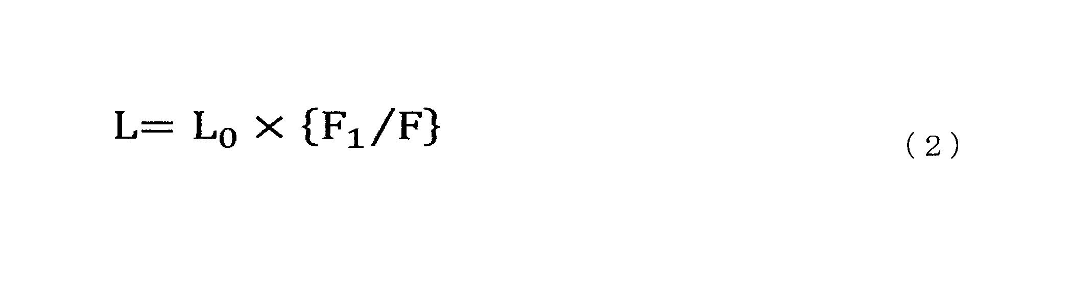
さらに、図20では、圧力センサ200は、1つの鍵盤につき、鍵盤の長手方向に沿って2つ設けられているが、本変形例においてはこれに限定されるものではなく、例えば、さらに鍵盤の短手方向に沿って2つの圧力センサ200が設けられていてもよい。また、本変形例においては、圧力センサ200の代わりに、3軸センサを用いてもよい。
(フィードバック例)
さらに、上述のような圧力センサ200による検出結果をユーザにフィードバックする方法の一例について、図22を参照して説明する。本変形例においては、例えば、図22に示すような表示画面820を用いて、圧力センサ200による検出結果をユーザにフィードバックすることができる。表示画面820には、鍵盤表示画面822が含まれており、例えば、被指導者が打鍵した位置(ここでは、鍵盤の長手方向における位置)をマーカ824a(図22では白丸)として表示することができる。この際、被指導者の手本となる演奏者の打鍵した位置をマーカ824b(図22では斜線のハッチングで示される丸)で併せて表示してもよい。このように表示することにより、ユーザは、被指導者と手本となる演奏者の打鍵の位置の違いを明確に認識することができる。さらに、本変形例においては、図22で示すような形態で打鍵した位置を示すことに限定されるものではない。例えば、本変形例においては、被指導者及び演奏者の打鍵した位置を、拡張現実(AR:Augmented Reality)技術を用いて、被指導者が打鍵する実空間上のピアノの鍵盤上に重畳して表示してもよい。この場合、表示の形態としては、図22のようなマーカ824であってもよく、アニメーション等であってもよい。さらに、この場合、例えば、被指導者の頭部等に装着される、透過型のヘッドマウントディスプレイ(Head Mounted Display:以下、「HMD」と称する)等により具現化することができる。なお、本変形例においては、上記HMDは、透過型のディスプレイに限定されるものではなく、非透過型のディスプレイであってもよい。後者の場合、HMDは、カメラ等の撮像装置を有してもよく、被指導者及び演奏者の打鍵した位置を、撮像した実空間上のピアノの鍵盤の画像に重畳して表示してもよい。さらに、後者の場合、HMDは、被指導者及び演奏者の打鍵した位置を、仮想現実(Virtual Reality)空間上に鍵盤を模式的に示す表示に重畳して表示してもよい。
さらに、上述のような圧力センサ200による検出結果をユーザにフィードバックする方法の一例について、図22を参照して説明する。本変形例においては、例えば、図22に示すような表示画面820を用いて、圧力センサ200による検出結果をユーザにフィードバックすることができる。表示画面820には、鍵盤表示画面822が含まれており、例えば、被指導者が打鍵した位置(ここでは、鍵盤の長手方向における位置)をマーカ824a(図22では白丸)として表示することができる。この際、被指導者の手本となる演奏者の打鍵した位置をマーカ824b(図22では斜線のハッチングで示される丸)で併せて表示してもよい。このように表示することにより、ユーザは、被指導者と手本となる演奏者の打鍵の位置の違いを明確に認識することができる。さらに、本変形例においては、図22で示すような形態で打鍵した位置を示すことに限定されるものではない。例えば、本変形例においては、被指導者及び演奏者の打鍵した位置を、拡張現実(AR:Augmented Reality)技術を用いて、被指導者が打鍵する実空間上のピアノの鍵盤上に重畳して表示してもよい。この場合、表示の形態としては、図22のようなマーカ824であってもよく、アニメーション等であってもよい。さらに、この場合、例えば、被指導者の頭部等に装着される、透過型のヘッドマウントディスプレイ(Head Mounted Display:以下、「HMD」と称する)等により具現化することができる。なお、本変形例においては、上記HMDは、透過型のディスプレイに限定されるものではなく、非透過型のディスプレイであってもよい。後者の場合、HMDは、カメラ等の撮像装置を有してもよく、被指導者及び演奏者の打鍵した位置を、撮像した実空間上のピアノの鍵盤の画像に重畳して表示してもよい。さらに、後者の場合、HMDは、被指導者及び演奏者の打鍵した位置を、仮想現実(Virtual Reality)空間上に鍵盤を模式的に示す表示に重畳して表示してもよい。
さらに、上記表示画面820は、図22に示すように、被指導者又は演奏者の打鍵による力の大きさFの経時変化を鍵盤ごとに表示する打鍵力表示画面826を含んでいてもよい。この際も、被指導者の手本となる演奏者の打鍵による力の大きさFの経時変化を、色や線種(図22では、実線と破線とに分けて表示)を変えて併せて表示してもよい。このように表示することにより、ユーザは、被指導者と手本となる演奏者の打鍵による力やその変化の違いを鍵盤ごとに明確に認識することができる。
このように、本変形例によれば、被指導者又は演奏者の打鍵、すなわち、打鍵による鍵盤の動き、打鍵の位置、打鍵による力の大きさ等を、表示画面820を介してリアルタイムにユーザにフィードバックすることができる。
なお、本変形例においては、3軸センサを用いた場合には、被指導者が打鍵した、鍵盤の長手方向における位置だけでなく、鍵盤の短手方向における位置を示してもよく、鍵盤の上下方向に沿った移動量の経時変化を示してもよい。このように表示することにより、3次元でのより詳細なセンシングデータをユーザにフィードバックすることができる。
<6.2.変形例2>
上述の変形例においては、圧力センサ200を用いたが、本実施形態においては、圧力センサ200の代わりにフォトリフレクタセンサ装置40を用いてもよい。そこで、変形例2として、図23から図29を参照して、フォトリフレクタセンサ装置40を用いた例を説明する。図23及び図24は、本変形例に係るフォトリフレクタセンサ装置40の構成を説明するための説明図である。また、図25は、本変形例に係るフォトリフレクタセンサ400の動作を説明するための説明図である。図26及び図27は、本変形例に係るフォトリフレクタセンサ装置40による測定結果のフィードバックの例を説明する説明図である。さらに、図28は、本変形例に係るフォトリフレクタセンサ装置40による測定結果の解析処理のフローチャートであり、図29は、本変形例に係るフォトリフレクタセンサ装置40による測定結果の解析処理を説明するための説明図である。
上述の変形例においては、圧力センサ200を用いたが、本実施形態においては、圧力センサ200の代わりにフォトリフレクタセンサ装置40を用いてもよい。そこで、変形例2として、図23から図29を参照して、フォトリフレクタセンサ装置40を用いた例を説明する。図23及び図24は、本変形例に係るフォトリフレクタセンサ装置40の構成を説明するための説明図である。また、図25は、本変形例に係るフォトリフレクタセンサ400の動作を説明するための説明図である。図26及び図27は、本変形例に係るフォトリフレクタセンサ装置40による測定結果のフィードバックの例を説明する説明図である。さらに、図28は、本変形例に係るフォトリフレクタセンサ装置40による測定結果の解析処理のフローチャートであり、図29は、本変形例に係るフォトリフレクタセンサ装置40による測定結果の解析処理を説明するための説明図である。
(構成)
まずは、図23から図25を参照して、フォトリフレクタセンサ装置40の構成を説明する。図23に示すように、本変形例に係るフォトリフレクタセンサ装置40は、各種のピアノの鍵盤の下に着脱可能に設けられる基板402と、当該基板402上に鍵盤に対応するように配列し、打鍵される鍵盤の動きを検出する複数のフォトリフレクタセンサ400とを有する。さらに、当該フォトリフレクタセンサ装置40は、フォトリフレクタセンサ400のセンシングデータを変換するAD変換器410と、変換されたセンシングデータを処理する情報処理装置412とを主に有する。本変形例に係るフォトリフレクタセンサ装置40は、各種のピアノの鍵盤の下に着脱可能に設けられることができる。従って、当該フォトリフレクタセンサ装置40は、ピアノの製造時又は出荷時にピアノに装着されてもよく、もしくは、ピアノの出荷後に後付されてもよい。
まずは、図23から図25を参照して、フォトリフレクタセンサ装置40の構成を説明する。図23に示すように、本変形例に係るフォトリフレクタセンサ装置40は、各種のピアノの鍵盤の下に着脱可能に設けられる基板402と、当該基板402上に鍵盤に対応するように配列し、打鍵される鍵盤の動きを検出する複数のフォトリフレクタセンサ400とを有する。さらに、当該フォトリフレクタセンサ装置40は、フォトリフレクタセンサ400のセンシングデータを変換するAD変換器410と、変換されたセンシングデータを処理する情報処理装置412とを主に有する。本変形例に係るフォトリフレクタセンサ装置40は、各種のピアノの鍵盤の下に着脱可能に設けられることができる。従って、当該フォトリフレクタセンサ装置40は、ピアノの製造時又は出荷時にピアノに装着されてもよく、もしくは、ピアノの出荷後に後付されてもよい。
詳細には、図24に示すように、各鍵盤(白鍵600及び黒鍵602)の下に、1つのフォトリフレクタセンサ400が設けられている。なお、図24においては、1オクターブ分の鍵盤12鍵(詳細には、白鍵600が7鍵、黒鍵602が5鍵)が示されており、12鍵の鍵盤のそれぞれに対応するようにフォトリフレクタセンサ400が設けられている。フォトリフレクタセンサ400は、各鍵盤の、被指導者又は演奏者から見て奥側の下方に位置するように設けられることが好ましい。さらに、各フォトリフレクタセンサ400は、一対の、光を出射する発光素子400aと、光と受光する受光素子400bとからなる。
より具体的には、図25に示すように、フォトリフレクタセンサ400の発光素子400aは、LED(Light Emitting Diode)等からなり、所定の波長を持つ光を出射することができる。さらに、フォトリフレクタセンサ400の受光素子400bは、フォトダイオード等からなり、受光した光量に応じて光電流(信号)を発生させることができる。従って、発光素子400aによって出射された光の一部は、白鍵600の下面で反射され、受光素子400bに到達し、受光素子400bによって検出することができる。例えば、白鍵600が被指導者又は演奏者によって打鍵されることで下方に移動した場合には、発光素子400aによって出射された光が受光素子400bによって検出されるまでに進む経路の長さが変化することから、受光素子400bによって検出する光の光量が変化する。従って、当該フォトリフレクタセンサ400によれば、白鍵600の上下方向の移動量に応じて、受光素子400bによって検出する光の光量が変化することから、フォトリフレクタセンサ400からの信号(電圧値)により白鍵600の移動量を検出することが可能である。
本変形例においては、フォトリフレクタセンサ400は、2ミリ秒程度の時間分解能と、0.01mm程度の空間分解能とを有するため、鍵盤の移動量の掲示変化を高精度に、取得することができる。より具体的には、本変形例においては、例えば、フォトリフレクタセンサ400の信号が所定の閾値を超えた瞬間を、鍵盤が移動を開始した時間(打鍵開始時間)(鍵盤の下降開始時)としてみなすことができる。本変形例においては、上記閾値は、フォトリフレクタセンサ400自体のノイズ(ホワイトノイズ等)やバラツキを考慮して適宜設定することが可能であり、例えば、鍵盤が上方に静止している際のフォトリフレクタセンサ400からの信号値の標準偏差の2倍に設定することができる。また、本変形例においては、鍵盤の移動量の時系列変化を高精度に取得することができることから、上述のような打鍵開始時間だけでなく、打鍵が終了した打鍵終了時間(鍵盤の上昇開始時)や、打鍵開始時間から打鍵終了時間までの打鍵時間等を鍵盤ごとに取得することができる。さらに、本変形例においては、打鍵の速度(鍵盤の移動速度)、加速度(鍵盤の移動加速度)、移動量の経時変化を鍵盤ごとに取得することができる。
(フィードバック例)
さらに、上述のようなフォトリフレクタセンサ400による検出結果をユーザにフィードバックする方法の一例について、図26及び図27を参照して説明する。なお、図26及び図27の時系列データ842、842a、842bにおいては、鍵盤が下方に移動した場合の鍵盤の移動量は、図中の上側になるように示されている。
さらに、上述のようなフォトリフレクタセンサ400による検出結果をユーザにフィードバックする方法の一例について、図26及び図27を参照して説明する。なお、図26及び図27の時系列データ842、842a、842bにおいては、鍵盤が下方に移動した場合の鍵盤の移動量は、図中の上側になるように示されている。
本変形例においては、被指導者又は演奏者に打鍵によって得られた鍵盤の移動量の時系列データ842から、イベント時間や特徴量を検出し、ユーザにフィードバックすることができる。ここで、イベント時間とは、打鍵開始時間や、打鍵終了時間、鍵盤が最も下方に位置した際の時間(下降終了時)、鍵盤が最も上方に位置した際の時間(上昇終了時)や、打鍵の速度が最大になった時間(最大速度到達時)、加速度が最大になった時間(最大加速度到達時)等のことを意味し、特に限定されない。また、本変形例においては、検出するイベント時間や特徴量についても、特に限定されるものではない。より具体的には、図26に示すように、イベント時間をマーカ844によって示すことにより、イベントが発生したタイミングを、ユーザにフィードバックすることができる。この際、どのようなイベント時間や特徴量を表示するかは、ユーザによって選択されてもよい。
さらに、この際、図27に示すように、被指導者の手本となる演奏者の打鍵による鍵盤の移動量の時系列データ842bを、色や線種を変えて併せて表示してもよい。例えば、図27においては、演奏者の打鍵による鍵盤の移動量の時系列データ842bは、被指導者の打鍵による鍵盤の移動量の時系列データ842aと異なる線種の線で示されている。このように表示することにより、ユーザは、被指導者と手本となる演奏者の打鍵による鍵盤の移動量の経時変化や特徴量等の違いを鍵盤ごとに明確に認識することができる。その結果、本変形例によれば、鍵盤を打鍵するタイミングや、鍵盤から指を離すタイミング、指を動かす速度等を視覚的に把握することが可能になることから、より技能の習得が容易、且つ、促進されることとなる。なお、本実施形態においては、打鍵による鍵盤の移動量については、移動量の時系列データ842bとして表示することに限定されるものではなく、鍵盤表示画面872(図33 参照)に示される鍵盤904(図33 参照)の色彩、色彩の濃淡(グラデーション)や模様を変化させることにより示してもよい。このような移動量の表示の詳細については後述する。
なお、本変形例においては、ユーザにフィードバックするデータは、鍵盤の移動量の経時変化に限定されるものではなく、移動速度、移動加速度等の経時変化であってもよい。さらに、本変形例においては、上述の経時変化とともに、上記マーカ844により、打鍵開始時間、打鍵終了時間、鍵盤が最も下方に位置した際の時間(下降終了時)、鍵盤が最も上方に位置した際の時間(上昇終了時)、打鍵の速度が最大になった時間(最大速度到達時)、鍵盤の下降中又は上昇中における最大速度到達時間、最大加速度到達時間等を表示してもよい。
(解析方法)
ところで、本変形例において、被指導者の打鍵による鍵盤の移動量の時系列データ842aと、手本となる演奏者の打鍵による鍵盤の移動量の時系列データ842bとを比較する際に、同一の演奏(楽曲、フレーズ、スケール、アルペジオ、和音等)を行っていた場合であっても、各打鍵のタイミングが異なることがある。このような場合、被指導者の打鍵による鍵盤の移動量の時系列データ842aと、演奏者の打鍵による鍵盤の移動量の時系列データ842bとを重畳して表示しても、両者の打鍵時間、打鍵の速度(鍵盤の移動速度)、加速度(鍵盤の移動加速度)等の違いを一目で把握することが難しいことがある。
ところで、本変形例において、被指導者の打鍵による鍵盤の移動量の時系列データ842aと、手本となる演奏者の打鍵による鍵盤の移動量の時系列データ842bとを比較する際に、同一の演奏(楽曲、フレーズ、スケール、アルペジオ、和音等)を行っていた場合であっても、各打鍵のタイミングが異なることがある。このような場合、被指導者の打鍵による鍵盤の移動量の時系列データ842aと、演奏者の打鍵による鍵盤の移動量の時系列データ842bとを重畳して表示しても、両者の打鍵時間、打鍵の速度(鍵盤の移動速度)、加速度(鍵盤の移動加速度)等の違いを一目で把握することが難しいことがある。
そこで、本変形例においては、上述の図27のように、被指導者の打鍵による鍵盤の移動量の時系列データ842aを、手本となる演奏者の打鍵による鍵盤の移動量の時系列データ842bとそのまま並べて表示する「フレーズ比較モード」表示の他に、他の表示モードでの表示を行ってもよい。具体的には、本変形例においては、一音ずつの鍵盤の移動量の経時変化を比較するための「単音比較モード」表示を行ってもよい。この「単音比較モード」は、被指導者の時系列データ842aにおける打鍵のタイミング(打鍵開始時間)と、演奏者の時系列データ842bにおける打鍵のタイミングとがそろうように、打鍵ごとに時系列データ842aを切り出して並べて、時系列データ842cを再構成することにより、表示することができる。以下に、当該「単音比較モード」表示を行うための解析方法について、図28及び図29を参照して説明する。
図28に示すように、本変形例に係る解析方法には、ステップS501からステップS509までの複数のステップが含まれている。以下に、本変形例に係る解析方法に含まれる各ステップの詳細を説明する。
(ステップS501)
まず、フォトリフレクタセンサ装置40は、被指導者の打鍵による鍵盤の移動量の時系列データ842aを取得する。
まず、フォトリフレクタセンサ装置40は、被指導者の打鍵による鍵盤の移動量の時系列データ842aを取得する。
(ステップS503)
次に、フォトリフレクタセンサ装置40は、ステップS501で得られた時系列データ842aから、各打鍵の開始時間と終了時間とを抽出する。この際、フォトリフレクタセンサ装置40は、フォトリフレクタセンサ400の信号が所定の閾値を超えた瞬間を、鍵盤が移動を開始した時間(打鍵開始時間)としてみなす。さらに、フォトリフレクタセンサ装置40は、フォトリフレクタセンサ400の信号が所定の閾値を下回った瞬間を、鍵盤から指が離れた時間(打鍵終了時間)としてみなす。このようにすることで、フォトリフレクタセンサ装置40は、各打鍵の開始時間と終了時間とを抽出することができる。そして、フォトリフレクタセンサ装置40は、抽出した時間に基づいて、各打鍵に対応する区間を、時系列区間842dとして、時系列データ842aから切り出して、保持する。
次に、フォトリフレクタセンサ装置40は、ステップS501で得られた時系列データ842aから、各打鍵の開始時間と終了時間とを抽出する。この際、フォトリフレクタセンサ装置40は、フォトリフレクタセンサ400の信号が所定の閾値を超えた瞬間を、鍵盤が移動を開始した時間(打鍵開始時間)としてみなす。さらに、フォトリフレクタセンサ装置40は、フォトリフレクタセンサ400の信号が所定の閾値を下回った瞬間を、鍵盤から指が離れた時間(打鍵終了時間)としてみなす。このようにすることで、フォトリフレクタセンサ装置40は、各打鍵の開始時間と終了時間とを抽出することができる。そして、フォトリフレクタセンサ装置40は、抽出した時間に基づいて、各打鍵に対応する区間を、時系列区間842dとして、時系列データ842aから切り出して、保持する。
(ステップS505)
そして、フォトリフレクタセンサ装置40は、上述のステップS503で切り出した各時系列区間842dから、打鍵開始時間、打鍵終了時間、鍵盤が最も下方に位置した際の時間(下降終了時)、鍵盤が最も上方に位置した際の時間(上昇終了時)、打鍵の速度が最大になった時間(最大速度到達時)、鍵盤の下降中又は上昇中における最大速度到達時間、最大加速度到達時間等の特徴量を抽出する。詳細には、例えば、第1の実施形態で説明した学習部348により、被指導者又は演奏者が打鍵した鍵盤の移動量の経時変化を、打鍵ごとに抽出し、抽出した各打鍵の時系列変化の一部(時系列区間842d)から、特徴量(第3の特徴情報)を抽出する。この際、フォトリフレクタセンサ装置40は、抽出した特徴量を、マーカ844を時系列区間842dに重畳することにより、可視化する。
そして、フォトリフレクタセンサ装置40は、上述のステップS503で切り出した各時系列区間842dから、打鍵開始時間、打鍵終了時間、鍵盤が最も下方に位置した際の時間(下降終了時)、鍵盤が最も上方に位置した際の時間(上昇終了時)、打鍵の速度が最大になった時間(最大速度到達時)、鍵盤の下降中又は上昇中における最大速度到達時間、最大加速度到達時間等の特徴量を抽出する。詳細には、例えば、第1の実施形態で説明した学習部348により、被指導者又は演奏者が打鍵した鍵盤の移動量の経時変化を、打鍵ごとに抽出し、抽出した各打鍵の時系列変化の一部(時系列区間842d)から、特徴量(第3の特徴情報)を抽出する。この際、フォトリフレクタセンサ装置40は、抽出した特徴量を、マーカ844を時系列区間842dに重畳することにより、可視化する。
(ステップS507)
次に、フォトリフレクタセンサ装置40は、切り出した時系列区間842dを、例えば、被指導者の手本となる演奏者の打鍵による鍵盤の移動量の時系列データ842bに合わせて並べることにより、再構成を行う。詳細には、図28及び図29に示すように、各時系列区間842dにおける打鍵開始時間が、時系列データ842bにおける対応する打鍵の打鍵開始時間と一致するように、各時系列区間842dを時間シフトさせて並べることにより、被指導者の時系列データを連続したデータとして再構成する。より具体的には、例えば、第1の実施形態で説明した学習部348は、抽出した各打鍵の時系列変化の一部(時系列区間842d)を、所定に規則に従って、連続したデータとして再度構成する。なお、以下の説明においては、再構成によって得られた被指導者の時系列データを、時系列データ842cと呼ぶ。
次に、フォトリフレクタセンサ装置40は、切り出した時系列区間842dを、例えば、被指導者の手本となる演奏者の打鍵による鍵盤の移動量の時系列データ842bに合わせて並べることにより、再構成を行う。詳細には、図28及び図29に示すように、各時系列区間842dにおける打鍵開始時間が、時系列データ842bにおける対応する打鍵の打鍵開始時間と一致するように、各時系列区間842dを時間シフトさせて並べることにより、被指導者の時系列データを連続したデータとして再構成する。より具体的には、例えば、第1の実施形態で説明した学習部348は、抽出した各打鍵の時系列変化の一部(時系列区間842d)を、所定に規則に従って、連続したデータとして再度構成する。なお、以下の説明においては、再構成によって得られた被指導者の時系列データを、時系列データ842cと呼ぶ。
(ステップS509)
さらに、フォトリフレクタセンサ装置40は、上述のステップS507で得られた時系列データ842cを、被指導者の手本となる演奏者の打鍵による鍵盤の移動量の時系列データ842bに重畳表示することにより、ユーザにフィードバックを行う。
さらに、フォトリフレクタセンサ装置40は、上述のステップS507で得られた時系列データ842cを、被指導者の手本となる演奏者の打鍵による鍵盤の移動量の時系列データ842bに重畳表示することにより、ユーザにフィードバックを行う。
本変形例においては、このように、被指導者の時系列データ842cにおける打鍵のタイミング(打鍵開始時間)と、演奏者の時系列データ842bにおける打鍵のタイミングとを一致させて、時系列データ842b、842cを表示する。本変形例においては、このように表示することにより、ユーザが、両者の打鍵時間、打鍵の速度(鍵盤の移動速度)、加速度(鍵盤の移動加速度)等の違いを一目で把握することができることから、より技能の習得が容易、且つ、促進されることとなる。
(フィードバック変形例)
さらに、上述のようなフォトリフレクタセンサ400による検出結果をユーザにフィードバックする方法は、以下のように変形してもよい。さらなる変形例について、図30及び図31を参照して説明する。図30及び図31は、本変形例に係るフォトリフレクタセンサ装置40による測定結果のフィードバックの例を説明する説明図である。なお、図30及び図31の時系列データ842においては、鍵盤が下方に移動した場合の鍵盤の移動量は、図中の下側になるように示されている。
さらに、上述のようなフォトリフレクタセンサ400による検出結果をユーザにフィードバックする方法は、以下のように変形してもよい。さらなる変形例について、図30及び図31を参照して説明する。図30及び図31は、本変形例に係るフォトリフレクタセンサ装置40による測定結果のフィードバックの例を説明する説明図である。なお、図30及び図31の時系列データ842においては、鍵盤が下方に移動した場合の鍵盤の移動量は、図中の下側になるように示されている。
本変形例においては、図30に示すように、表示画面880の下段には、鍵盤表示画面882と、鍵盤表示画面882に表示された鍵盤に対応するように各鍵盤の移動量の時系列データ842を表示する時系列データ表示884とが示されている。なお、当該時系列データ表示884は、被指導者の打鍵による鍵盤の移動量の時系列データ842aと、被指導者の手本となる演奏者の打鍵による鍵盤の移動量の時系列データ842bとを表示するものとする。
さらに、本変形例においては、図30に示すように、表示画面880の下段には、楽譜表示画面886が示されている。楽譜表示画面886は、枠890を持ち、枠890内の音符に対応する箇所が、時系列データ表示884が表示する時系列データ842に対応する。また、楽譜表示画面886の下側には、スライドバー888が設けられており、ユーザがスライドバー888を移動させることにより、楽譜表示画面886の枠890が移動し、時系列データ表示884に表示させる時系列データ842の範囲を変えることができる。すなわち、本変形例においては、ユーザにフィードバックする時系列データ842と同期して、対応する楽譜の一部を表示することができる。この際、ユーザにフィードバックする時系列データ842と同期して、楽譜の一部に対応する音声を出力してもよい。このように出力することで、ユーザは、演奏(楽曲、フレーズ等)のうちのどの部分に対応する時系列データ842を表示しているかを、容易に把握することができる。なお、本変形例においては、スライドバー888により楽譜表示画面886の枠890を移動させて、時系列データ表示884に表示させる時系列データ842の範囲を変えることに限定されるものではない。例えば、本変形例においては、時系列データ表示884に表示された時系列データ842の範囲をスライドバー888により移動させることにより、楽譜表示画面886の枠890を移動させてもよい。さらに、本変形例においては、スライドバー888に限定されるものではなく、楽譜表示画面886又は時系列データ表示884に対してスワイプしたり、ピンチイン、ピンチアウトしたりすることにより、楽譜表示画面886に表示される範囲や時系列データ表示884に表示させる時系列データ842の範囲を変えてもよい。
また、本変形例においては、図31に示すような表示画面880aを用いてもよい。当該表示画面880aにおいては、ユーザがスライドバー888を移動させることにより、楽譜表示画面886の枠890の大きさが変化して、時系列データ表示884に表示させる時系列データ842の範囲を変えることができる。すなわち、本変形例においては、ユーザは、時系列データ表示884に表示させる時系列データ842の時間範囲を、ズームイン又はズームアウトすることにより、選択することができる。このように表示することにより、ユーザは、演奏(楽曲、フレーズ等)のうちの所望する範囲の時系列データ842を容易にズームイン又はズームアウト表示させることができることから、特徴量等を容易に把握することが可能となる。例えば、本変形例においては、時系列データ842の時間範囲をズームインすることができるため、被指導者が「ドミソ」の和音を弾いた際に得られた時系列データ842と、手本となる演奏者の時系列データ842における3音の打鍵タイミングとのズレを可視化することができる。そして、本変形例によれば、このような微細なズレを可視化することもできるため、ユーザは、聴覚等では認識しにくいズレを容易に認識できるようになるため、被指導者のより巧緻な演奏の習得を促進することができる。なお、本変形例においては、スライドバー888により楽譜表示画面886の枠890の大きさを変化させて、時系列データ表示884に表示させる時系列データ842の範囲を変えることに限定されるものではない。例えば、本変形例においては、時系列データ表示884に表示された時系列データ842の範囲の大きさをスライドバー888により変化させることにより、楽譜表示画面886の枠890の大きさを変化させてもよい。すなわち、本変形例においては、楽譜表示画面886と時系列データ表示884とは、互いに同期して表示されることとなる。
また、本変形例においては、被指導者の時系列データ842と比較する際に用いる他者の時系列データ842は、複数の熟練者の時系列データ842から抽出された平均値等の代表値(集合知)からなる時系列データ842であってもよく、もしくは、特定の熟練者の時系列データ842であってもよい。さらに、本変形例においては、比較する時系列データ842は、被指導者の熟練のレベルに応じて、段階的にレベルを上げるように選択することが好ましい。このようにすることで、被指導者のモチベーションを効果的に刺激し、被指導者の演奏のレベルをよりスムーズに向上させることができる。
さらに、本変形例においては、比較する時系列データ842の演奏者の手の大きさ等で、時系列データ842を予めタグ付しておくことが好ましい。このようなタグ付を行った場合、本変形例においては、被指導者が手の大きさに合わせて、比較する時系列データ842を自動的に選択することが可能となる。さらに、本変形例においては、上述のような手の大きさに限定されるものではなく、演奏者の握力、手の形状、体の大きさ、熟達度、年齢、性別等の属性情報で、時系列データ842を予めタグ付してもよい。本変形例においては、このようにタグ付することで、個人差を考慮した上で、好適な比較用の時系列データ842を選択することができ、個人に合わせたレッスンを提供することができる。
なお、本変形例においては、3つ以上の複数の時系列データ842を比較することも可能であり、例えば、被指導者の過去の時系列データ842と重畳して表示することにより、被指導者の上達の軌跡を確認する等を行うことができる。さらに、本変形例においては、被指導者の、上達の度合いを数値化したり、熟達の変化をグラフ化したりしてもよい。
<6.3.変形例3>
さらに、これまで説明したフィードバックは、主に画面による表示が中心であったが、本実施形態においては、被指導者に対して触覚刺激を行うことにより、フィードバックを行ってもよい。そこで、以下においては、変形例3として、被指導者の筋活動量をセンシングし、センシングデータに基づいて、バイブレータ612(図32 参照)により触覚刺激を行う例を、図32を参照して説明する。図32は、本変形例に係る筋活動量センサ装置60の構成を説明するための説明図である。
さらに、これまで説明したフィードバックは、主に画面による表示が中心であったが、本実施形態においては、被指導者に対して触覚刺激を行うことにより、フィードバックを行ってもよい。そこで、以下においては、変形例3として、被指導者の筋活動量をセンシングし、センシングデータに基づいて、バイブレータ612(図32 参照)により触覚刺激を行う例を、図32を参照して説明する。図32は、本変形例に係る筋活動量センサ装置60の構成を説明するための説明図である。
(構成)
まずは、図32を参照して、筋活動量センサ装置60の構成を説明する。図32に示すように、筋活動量センサ装置60は、例えば、被指導者の親指、人差し指、中指等の根元に装着され、被指導者の各指の筋活動量を検出するとともに、検出した筋活動量に基づき振動によりフィードバックを行うことができる。詳細には、本変形例に係る筋活動量センサ装置60は、筋活動量をセンシングする筋電位センサ610と、触覚刺激によりフィードバックを行うバイブレータ612とを有する。本変形例においては、筋活動量センサ装置60は、筋電位センサ610とバイブレータ612とが一体化した装置であることが好ましい。さらに、筋活動量センサ装置60は、筋電位センサ610のセンシングデータを変換するAD変換器620と、バイブレータ612を制御するマイクロコントローラ630と、変換されたセンシングデータを処理し、且つ、マイクロコントローラ630を制御する情報処理装置632とを接続される。
まずは、図32を参照して、筋活動量センサ装置60の構成を説明する。図32に示すように、筋活動量センサ装置60は、例えば、被指導者の親指、人差し指、中指等の根元に装着され、被指導者の各指の筋活動量を検出するとともに、検出した筋活動量に基づき振動によりフィードバックを行うことができる。詳細には、本変形例に係る筋活動量センサ装置60は、筋活動量をセンシングする筋電位センサ610と、触覚刺激によりフィードバックを行うバイブレータ612とを有する。本変形例においては、筋活動量センサ装置60は、筋電位センサ610とバイブレータ612とが一体化した装置であることが好ましい。さらに、筋活動量センサ装置60は、筋電位センサ610のセンシングデータを変換するAD変換器620と、バイブレータ612を制御するマイクロコントローラ630と、変換されたセンシングデータを処理し、且つ、マイクロコントローラ630を制御する情報処理装置632とを接続される。
詳細には、筋電位センサ610は、被指導者の手の皮膚690の一部に装着され、筋肉692(詳細には、筋線維)の収縮活動によって生じる筋電位の変化を検出することができる。さらに、検出された筋電位のセンシングデータは、AD変換器620によって、アナログ信号からデジタル信号に変換され、情報処理装置632に出力される。また、情報処理装置632は、筋電位のセンシングデータ680を所定の閾値682と比較し、比較結果に基づいて、マイクロコントローラ630に信号を出力することにより、バイブレータ612を制御することができる。バイブレータ612は、例えば、スマートフォン等に搭載される振動装置であり、マイクロコントローラ630を介した制御により、振動の振幅や振動周波数を変えることができる。なお、本変形例においては、筋電位センサ610が筋活動量を検出してから、バイブレータ612が振動するまでにかかる時間がより短くなりように構成することが好ましく、このように構成することで、被指導者に、筋肉の弛緩又は緊張さるタイミングを、より正確にリアルタイムにフィードバックすることができる。
(フィードバック例)
次に、上述のような筋活動量センサ装置60による検出結果を被指導者にフィードバックする方法の詳細について説明する。
次に、上述のような筋活動量センサ装置60による検出結果を被指導者にフィードバックする方法の詳細について説明する。
詳細には、先に説明したように、情報処理装置632は、筋電位のセンシングデータ680を所定の閾値682と比較する。当該所定の閾値682は、例えば、該当する筋肉692の最大筋収縮時における電位に対して何パーセントというように設定することができる。そして、情報処理装置632は、筋電位のセンシングデータ680が所定の閾値682を超える(もしくは、所定の閾値を下回る)と、マイクロコントローラ630に信号を出力することにより、バイブレータ612を振動させる。
より具体的には、本変形例においては、筋電位の大きさに応じて、バイブレータ612の振動周波数を変化させてもよい。例えば、筋電位が所定の閾値を超えた場合には、情報処理装置632は、該当する筋肉692が必要以上に緊張した状態であるとして、被指導者に対して、バイブレータ612を介して高い周波数で振動を与える。このようにすることで、被指導者は筋肉692が「力みの状態」にあることを認識し、該当する筋肉を脱力することができる。この際の振動周波数は、人の振動に対する感度が最も高くなると言われる250Hz程度とすることが好ましい。特に、ピアノの演奏においては、筋肉692を脱力することが求められる場合があるが、実際に脱力を自覚して演奏することが難しい。しかしながら、本変形例によれば、被指導者に自身の「力みの状態」を容易に認識させることができることから、被指導者は筋肉692の脱力を行うことができる。
一方、例えば、筋電位が所定の閾値を下回る場合には、情報処理装置632は、該当する筋肉692をより緊張した状態にすることが求められているとして、被指導者に対して、バイブレータ612を介して低い周波数で振動を与える。このようにすることで、被指導者は筋肉692をより緊張した状態にすることができる。
なお、上述の説明においては、情報処理装置632は振動数を制御していたが、本変形例においては振幅の大きさを制御してもよく、両方を制御してもよい。例えば、情報処理装置632が振動数及び振幅の両方を制御することにより、脱力か緊張かのいずれかの方向に筋肉692をコントロールすることが求められているかを被指導者にフィードバックするだけでなく、どの程度脱力させればよいのか、もしくは、どの程度緊張させればよいかの程度も、被指導者にフィードバックすることができる。
また、本変形例においては、複数の筋肉692の筋電位を検出した場合には、上述した実施形態と同様に、複数の筋肉692の協調度に基づいて、被指導者にフォードバックしてもよい。本変形例においては、例えば、親指の筋肉692と小指の筋肉692とを同時に緊張させる(収縮させる)ことが求められる状況において、親指の筋肉692と小指の筋肉692とに振動を印可することにより、いずれかの筋肉692をより早く緊張させるべきか、より強く緊張させるべきかの情報を被指導者にフォードバックすることができる。このようにすることで、ピアノの演奏時に求められる複数の筋肉692の協調動作を、触覚を介して被指導者は習得することができる。
なお、筋電位は、被指導者の皮膚690のインピーダンスや脂肪等の影響により、ノイズが含まれることとなる。すなわち、筋肉692の安静時であっても、筋電位の大きさには個人差が存在する。そこで、本変形例においては、事前に、被指導者の筋肉692の安静時の筋電位(バックグラウンドノイズ)と、最大筋収縮時の筋電位とを測定する。そして、本変形例においては、安静時の筋電位と最大筋収縮時の筋電位との差を用いて、新たに検出された筋電位を正規化することにより、筋電位における個人差に対応することができ、精度よく筋肉692の弛緩、又は、緊張によって発生する筋電位を検出することができる。
また、上述の説明においては、筋電位自体を所定の閾値と比較して、振動によって被指導者にフィードバックしていたが、本変形例においては、これに限定されるものではない。例えば、本変形例においては、筋電位が所定の時間を超えて所定の閾値を超えた場合、もしくは、筋電位が所定の時間を超えて所定の閾値を下回った場合、振動によって被指導者にフィードバックしてもよい。すなわち、本変形例においては、筋電位に限定されるものではなく、筋活動時間等を用いてもよい。
また、本変形例においては、手指の筋肉692に限定されるものではなく、筋電位を検出することができれば、他の身体上の部分の筋肉であってもよく、特に限定されるものではない。さらに、本変形例においては、関節角度の情報や角速度といった筋電位以外の生体情報を用いてもよい。
(組み合わせ)
さらに、本変形例に係る筋活動量センサ装置60は、上述した力覚機構710と組み合わせて用いてもよい。詳細には、被指導者の指先に、筋活動量センサ装置60を装着し、手指の関節に、上述の外骨格ロボット712を装着してもよい。この場合、該当する筋肉をどの程度脱力させればよいのか、もしくは、どの程度緊張させればよいかの程度は、筋活動量センサ装置60によって、被指導者にフィードバックする。一方、どのような方向に、どのような方向で指を動かすか等の情報は、外骨格ロボット712によって被指導者にフィードバックする。
さらに、本変形例に係る筋活動量センサ装置60は、上述した力覚機構710と組み合わせて用いてもよい。詳細には、被指導者の指先に、筋活動量センサ装置60を装着し、手指の関節に、上述の外骨格ロボット712を装着してもよい。この場合、該当する筋肉をどの程度脱力させればよいのか、もしくは、どの程度緊張させればよいかの程度は、筋活動量センサ装置60によって、被指導者にフィードバックする。一方、どのような方向に、どのような方向で指を動かすか等の情報は、外骨格ロボット712によって被指導者にフィードバックする。
このように組み合わせることにより、指先における触覚と、関節における力覚とによって、被指導者は、多感覚情報統合学習(マルチモダリティラーニング)を行うことができる。さらに、本変形例においては、視覚によるフィードバックや、聴覚によるフィードバックとも組み合わせることで、被指導者は、例えば、自身や他者(例えば、熟練者)との間における動作の違いや、自身の過去と現在における動作の違いをより容易に把握することができる。従って、本変形例においては、被指導者の「コツ」の習得支援、すなわち、パフォーマンスの習得支援を行うことができる。
さらに、本変形例においては、力覚機構710は、手指の関節に印加する力の程度や、印加する速度を変更してもよい(例えば、倍速、スローモーション等)。その際に、被指導者が演奏したピアノの音を出力してもよい。例えば、被指導者の手指の動きの速さを力覚機構710で再現して、被指導者の手指に力覚的に印加することにより、被指導者は、現時点での、自身の手指の動きの速さの限界を認識することができる。また、例えば、力覚機構710により、段階的に動きを早くしながら被指導者の手指に力覚的に印加することにより、被指導者の手指の動きが速くなるように誘導してもよい。
以上のように、本開示の第2の実施形態の各変形例によれば、各種のセンサを得られた、ユーザのパフォーマンスに関する情報を、当該ユーザにフィードバックするパフォーマンスの習得支援に利用可能な情報処理装置、情報処理方法及びプログラムを提供することができる。さらに、本実施形態の各変形例によれば、被指導者のパフォーマンスの習得支援、例えば、リモートレッスンやセルフレッスン等を行うことができる。
なお、以上説明した本開示の各実施形態、各実施例及び各変形例は、互いに組み合わせて実施することが可能であり、これらについても、本開示の技術的範囲に属するものと了解される。
<<7.第3の実施形態>>
上述の本開示の実施形態に係るフィードバック方法は、以下のように変形することも可能である。以下に、本開示の第3の実施形態として、各種のフィードバックの例を図33及び図34を参照して説明する。図33及び図34は、本開示の第3の実施形態に係るフィードバックの例を説明する説明図である。
上述の本開示の実施形態に係るフィードバック方法は、以下のように変形することも可能である。以下に、本開示の第3の実施形態として、各種のフィードバックの例を図33及び図34を参照して説明する。図33及び図34は、本開示の第3の実施形態に係るフィードバックの例を説明する説明図である。
上述した実施形態と同様に、ユーザ側装置70は、受信したフィードバック情報506に基づき、被指導者にフィードバックを行う。詳細には、ユーザ側装置70は、図33に示すような表示画面902を演奏中又は演奏後の被指導者に向けて表示する。当該表示画面902は、その右側に、鍵盤を模式的示す鍵盤表示画面872を含み、その左側に、被指導者(もしくは、演奏者)が該当する鍵盤を打鍵する際の手指の速度の時系列データを示す時系列データ表示874を含む。これら鍵盤表示画面872及び時系列データ表示874は、例えば、被指導者等の演奏による各鍵盤の動きを再現したものであり、再現の際に速度を変更したり、再現する鍵盤や演奏の範囲を変更したりと、ユーザが所望する条件で再現することができる。
詳細には、鍵盤表示画面872に含まれる各鍵盤904は、被指導者(もしくは、演奏者)の演奏による各鍵盤の動きをアニメーションによって再現し(例えば、再現アニメーション速度は、ユーザの所望する速度に設定できる)、さらに、色彩、色彩の濃淡(グラデーション)や模様の違いによって、被指導者等が演奏の際に打鍵した鍵盤の移動量を示すことができる。本実施形態においては、例えば、鍵盤が底近くまで下がるほど該当する鍵盤904の色を濃く示し、鍵盤が上に上がるほど該当する鍵盤904の色を薄く示す。本実施形態においては、鍵盤表示画面872に含まれる各鍵盤904の動きによって該当する鍵盤の移動量を再現するだけでなく、各鍵盤904の色彩等によって移動量を示すことができることから、ユーザは、各鍵盤の移動量を容易に把握することができる。さらに、本実施形態においては、他のセンサ装置10(例えば、被指導者等の手に装着されたグローブ型のセンサ装置10、筋活動量センサ装置60等)で取得したセンシングデータ500に基づいて指の動き等を再現したアニメーションを、各鍵盤904等に重ねて表示してもよい。
また、本実施形態においては、被指導者等の演奏による各鍵盤の動きをアニメーションによって再現した各鍵盤904の動きに同期して、上記演奏時に取得された演奏音を再生してもよい。さらに、演奏音の再生についても、動きの再現と同様に、ユーザが所望する速度に設定することができる。
加えて、本実施形態においては、表示画面902は、移動量だけでなく、移動速度に関する情報も表示してもよい。例えば、図33中の三角形状のタイミング表示906aは、鍵盤の下降速度(打鍵速度又は移動速度)が最大になるタイミング付近で表示され、図33中の三角形状のタイミング表示906bは、鍵盤の上昇速度が最大になるタイミング付近で表示される。なお、タイミング表示906の形状は、図33に示されるような三角形に限定されるものではない。また、図中の四角形状のバー表示908a、908bは、棒グラフのように鍵盤の移動速度を示すバーである。例えば、鍵盤が下に向かって移動する際には、当該鍵盤の移動速度に応じて、所定の色彩又は模様を持つバー表示908が下に向かって伸び、一方、鍵盤が上昇する際には、所定の色彩又は模様を持つバー表示908が上に向かって伸びるように示される。本実施形態においては、上述したようなタイミング表示906やバー表示908を用いて表示を行うことにより、被指導者等が、鍵盤の移動速度、すなわち、打鍵速度や速度が最大になるタイミングを直感的に把握することができる。
また、本実施形態においては、お手本となるロールモデルとの直接的な比較も可能である。例えば、表示画面902においては、被指導者の演奏による鍵盤の動きをアニメーションで再現した上に、ワイヤーフレーム等を用いて、お手本となるロールモデルの演奏による鍵盤の動きを重ねてアニメーションとして描画してもよい。
また、本実施形態においては、図34に示すような表示画面910を用いてフィードバックを行ってもよい。当該表示画面910も、上述と同様に、その右側に、鍵盤を模式的示す鍵盤表示画面872を含み、その左側に、被指導者(もしくは、演奏者)が該当する鍵盤を打鍵する際の手指の速度の時系列データを示す時系列データ表示874を含む。
さらに、本実施形態においては、ピアノの鍵盤部に、ウレタン等からなる弾性変形可能な部材と、位置センサとを設置するものとする。詳細には、本実施形態においては、上記部材は、各鍵盤が所定の距離(例えば10mm)だけ下方に移動した際に、当該鍵盤の底面に接するように設けられる。さらに、上記位置センサは、各鍵盤の底面に設けられる。当該位置センサは、精密な位置の計測が可能であることから、鍵盤が深く打鍵された場合、鍵盤の底面が上記部材に接触し、さらに鍵盤が深く押し付けられることから上記部材がわずかに変形し、当該鍵盤が上記所定の距離よりもわずかに深く沈み込む状態を検出することができる。
従って、図34に示すように、鍵盤表示画面872に含まれる各鍵盤904は、被指導者(もしくは、演奏者)の演奏による各鍵盤の動きをアニメーションによって再現するとともに、色彩、色彩の濃淡(グラデーション)、模様等の違いによって、被指導者(もしくは、演奏者)が演奏の際に打鍵した鍵盤の深さを示すことができる。具体的には、図34においては、鍵盤904の縞状の模様によって、該当する鍵盤が所定の距離よりも深く沈みこんでいること、すなわち、不必要に鍵盤を押さえつけていることを示している。不必要に鍵盤を押さえつけることは、響きを減弱させ、音色を硬くさせ、さらには、演奏者が無駄なエネルギを使うことにもつながることから、一般的には、避けるべきとされている。本実施形態においては、該当する鍵盤が所定の距離よりも深く沈みこんでいることを示すために鍵盤904の色彩、模様等を変化させて表示することから、被指導者等は、各鍵盤の押さえつけの程度を容易に把握することができ、その結果、一般的に避けるべきとされている不必要な鍵盤の押さえつけを行わないように意識して演奏するようになる。
<<8.補足>>
なお、先に説明した本開示の実施形態は、例えば、コンピュータを本実施形態に係る情報処理装置として機能させるためのプログラム、及びプログラムが記録された一時的でない有形の媒体を含みうる。また、プログラムをインターネット等の通信回線(無線通信も含む)を介して頒布してもよい。
なお、先に説明した本開示の実施形態は、例えば、コンピュータを本実施形態に係る情報処理装置として機能させるためのプログラム、及びプログラムが記録された一時的でない有形の媒体を含みうる。また、プログラムをインターネット等の通信回線(無線通信も含む)を介して頒布してもよい。
また、上述した本開示の実施形態の処理における各ステップは、必ずしも記載された順序に沿って処理されなくてもよい。例えば、各ステップは、適宜順序が変更されて処理されてもよい。また、各ステップは、時系列的に処理される代わりに、一部並列的に又は個別的に処理されてもよい。さらに、各ステップの処理方法についても、必ずしも記載された方法に沿って処理されなくてもよく、例えば、他の機能部によって他の方法で処理されていてもよい。
以上、添付図面を参照しながら本開示の好適な実施形態について詳細に説明したが、本開示の技術的範囲はかかる例に限定されない。本開示の技術分野における通常の知識を有する者であれば、特許請求の範囲に記載された技術的思想の範疇内において、各種の変更例または修正例に想到し得ることは明らかであり、これらについても、当然に本開示の技術的範囲に属するものと了解される。
また、本明細書に記載された効果は、あくまで説明的または例示的なものであって限定的ではない。つまり、本開示に係る技術は、上記の効果とともに、または上記の効果に代えて、本明細書の記載から当業者には明らかな他の効果を奏しうる。
なお、以下のような構成も本開示の技術的範囲に属する。
(1)
ユーザの身体の複数の部分が動作することによって行われるパフォーマンスにおける複数の運動要素の状態をセンシングする1つ又は複数のセンサから複数のセンシングデータを取得するセンシングデータ取得部と、
取得した前記複数のセンシングデータから、前記運動要素の動作協調性を示す協調情報を算出する算出部と、
算出した前記協調情報に基づいて、前記ユーザにフィードバック情報を通知する通知部と、
を備える情報処理装置。
(2)
前記算出部は、予め設定されたパフォーマンスの状態と関係を持つ前記運動要素の協調情報を算出する、上記(1)に記載の情報処理装置。
(3)
各種のパフォーマンスの状態と、当該各パフォーマンスの状態と関係を持つ前記運動要素の協調情報との関係を示す関係情報を格納する記憶部をさらに備え、
前記算出部は、前記記憶部に予め格納された前記関係情報に基づいて、前記取得した複数のセンシングデータから前記協調情報を算出する、
上記(2)に記載の情報処理装置。
(4)
複数の前記パフォーマンスの状態と、当該複数のパフォーマンスの状態の各々に対応する前記複数のセンシングデータとを用いて、前記各種のパフォーマンスの状態と前記運動要素の協調情報との関係を機械学習し、前記関係情報を習得する学習部をさらに備える、
上記(3)に記載の情報処理装置。
(5)
前記学習部は、前記関係情報に対して多変量解析を行って、前記各パフォーマンスの状態を特徴づける前記協調情報を第1の特徴情報として抽出する、上記(4)に記載の情報処理装置。
(6)
前記学習部は、前記取得した複数のセンシングデータに基づいて、前記ユーザの前記パフォーマンスを特徴づける前記協調情報を第2の特徴情報として抽出する、上記(4)に記載の情報処理装置。
(7)
前記学習部は、前記第2の特徴情報に基づき、前記ユーザの前記パフォーマンスの状態を分類する、上記(6)に記載の情報処理装置。
(8)
前記予め設定されたパフォーマンスの状態に関係する前記第1の特徴情報を選択し、
選択した前記第1の特徴情報と、前記算出部により算出された前記ユーザの前記協調情報とを比較し、
比較結果に基づき、前記フィードバック情報を生成する、
比較部をさらに備える、
上記(5)に記載の情報処理装置。
(9)
前記通知部は、生成された前記フィードバック情報に基づき、前記フィードバック情報の通知の形態を選択する、上記(8)に記載の情報処理装置。
(10)
前記通知部は、表示装置を制御して所定の画像を表示させることにより、前記ユーザに対して前記フィードバック情報を通知する、上記(9)に記載の情報処理装置。
(11)
前記通知部は、前記ユーザが打鍵した鍵盤上の位置を表示することにより、前記ユーザに対して前記フィードバック情報を通知する、上記(10)に記載の情報処理装置。
(12)
前記通知部は、前記ユーザが打鍵した鍵盤の移動量、移動速度、移動加速度のうちの少なくとも1つの経時変化を表示することにより、前記ユーザに対して前記フィードバック情報を通知する、上記(10)又は(11)に記載の情報処理装置。
(13)
前記経時変化とともに、前記鍵盤の下降開始時、下降終了時、上昇開始時、上昇終了時、及び、前記鍵盤の下降中又は上昇中における最大速度到達時、最大加速度到達時のうちの少なくとも1つを表示することにより、前記ユーザに対して前記フィードバック情報を通知する、上記(12)に記載の情報処理装置。
(14)
前記通知部は、前記経時変化と同期して、前記ユーザの打鍵に対応する楽譜を表示する、上記(12)又は(13)に記載の情報処理装置。
(15)
前記通知部は、前記ユーザの身体に装着されたウェアラブル装置を制御して前記ユーザに対して触覚刺激を行わせることにより、前記ユーザに対して前記フィードバック情報を通知する、上記(9)に記載の情報処理装置。
(16)
前記通知部は、前記ユーザの身体の一部の筋活動量と閾値との比較結果に基づき、前記ユーザに対して触覚刺激を行わせることにより、前記ユーザに対して前記フィードバック情報を通知する、上記(15)に記載の情報処理装置。
(17)
前記通知部は、音声出力装置を制御して所定の音を出力させることにより、前記ユーザに対して前記フィードバック情報を通知する、上記(9)に記載の情報処理装置。
(18)
前記ユーザの属性情報を取得する属性情報取得部をさらに備え、
前記比較部は、取得した前記属性情報に基づいて、前記第1の特徴情報を選択する、
上記(8)に記載の情報処理装置。
(19)
前記パフォーマンスの状態は、当該パフォーマンスにおける前記ユーザの前記運動要素の運動パターン、運動速度、運動正確性、及び運動量のうちの少なくとも1つによって示される、上記(2)に記載の情報処理装置。
(20)
前記パフォーマンスの状態は、当該パフォーマンスによって生じる結果の状態によって示される、上記(2)に記載の情報処理装置。
(21)
前記複数のセンシングデータは、前記ユーザに装着された、加速度センサ、ジャイロセンサ、角速度センサ、振動センサ、圧力センサ、生体情報センサ、曲げセンサ、又は、位置センサから得られるセンシングデータのうちの少なくとも1つを含む、上記(1)~(20)のいずれか1つに記載の情報処理装置。
(22)
前記複数のセンシングデータは、前記ユーザを撮像する撮像装置、前記ユーザの身体の一部によって印加される圧力をセンシングする圧力センサ、又は、前記ユーザにおける核磁気共鳴をセンシングする核磁気共鳴センサから得られるセンシングデータのうちの少なくとも1つを含む、上記(1)~(21)のいずれか1つに記載の情報処理装置。
(23)
前記複数のセンシングデータは、前記ユーザの身体の一部によって打鍵される鍵盤の動きをセンシングするフォトリフレクタセンサから得られるセンシングデータのうちの少なくとも1つを含む、上記(1)~(22)のいずれか1つに記載の情報処理装置。
(24)
前記フォトリフレクタセンサは、各種のピアノの鍵盤の下に着脱可能に設けられる、上記(23)に記載の情報処理装置。
(25)
前記複数のセンシングデータは、前記パフォーマンスによって生じる音をセンシングする収音装置から得られたセンシングデータを含む、上記(1)~(24)のいずれか1つに記載の情報処理装置。
(26)
ユーザの身体の複数の部分が動作することによって行われるパフォーマンスにおける複数の運動要素の状態をセンシングする1つ又は複数のセンサから複数のセンシングデータを取得することと、
取得した前記複数のセンシングデータから、前記運動要素の動作協調性を示す協調情報を算出することと、
算出した前記協調情報に基づいて、前記ユーザにフィードバック情報を通知することと、
を含む、情報処理方法。
(27)
ユーザの身体の複数の部分が動作することによって行われるパフォーマンスにおける複数の運動要素の状態をセンシングする1つ又は複数のセンサから複数のセンシングデータを取得する機能と、
取得した前記複数のセンシングデータから、前記運動要素の動作協調性を示す協調情報を算出する機能と、
算出した前記協調情報に基づいて、前記ユーザにフィードバック情報を通知する機能と、
をコンピュータに実現させるためのプログラム。
(1)
ユーザの身体の複数の部分が動作することによって行われるパフォーマンスにおける複数の運動要素の状態をセンシングする1つ又は複数のセンサから複数のセンシングデータを取得するセンシングデータ取得部と、
取得した前記複数のセンシングデータから、前記運動要素の動作協調性を示す協調情報を算出する算出部と、
算出した前記協調情報に基づいて、前記ユーザにフィードバック情報を通知する通知部と、
を備える情報処理装置。
(2)
前記算出部は、予め設定されたパフォーマンスの状態と関係を持つ前記運動要素の協調情報を算出する、上記(1)に記載の情報処理装置。
(3)
各種のパフォーマンスの状態と、当該各パフォーマンスの状態と関係を持つ前記運動要素の協調情報との関係を示す関係情報を格納する記憶部をさらに備え、
前記算出部は、前記記憶部に予め格納された前記関係情報に基づいて、前記取得した複数のセンシングデータから前記協調情報を算出する、
上記(2)に記載の情報処理装置。
(4)
複数の前記パフォーマンスの状態と、当該複数のパフォーマンスの状態の各々に対応する前記複数のセンシングデータとを用いて、前記各種のパフォーマンスの状態と前記運動要素の協調情報との関係を機械学習し、前記関係情報を習得する学習部をさらに備える、
上記(3)に記載の情報処理装置。
(5)
前記学習部は、前記関係情報に対して多変量解析を行って、前記各パフォーマンスの状態を特徴づける前記協調情報を第1の特徴情報として抽出する、上記(4)に記載の情報処理装置。
(6)
前記学習部は、前記取得した複数のセンシングデータに基づいて、前記ユーザの前記パフォーマンスを特徴づける前記協調情報を第2の特徴情報として抽出する、上記(4)に記載の情報処理装置。
(7)
前記学習部は、前記第2の特徴情報に基づき、前記ユーザの前記パフォーマンスの状態を分類する、上記(6)に記載の情報処理装置。
(8)
前記予め設定されたパフォーマンスの状態に関係する前記第1の特徴情報を選択し、
選択した前記第1の特徴情報と、前記算出部により算出された前記ユーザの前記協調情報とを比較し、
比較結果に基づき、前記フィードバック情報を生成する、
比較部をさらに備える、
上記(5)に記載の情報処理装置。
(9)
前記通知部は、生成された前記フィードバック情報に基づき、前記フィードバック情報の通知の形態を選択する、上記(8)に記載の情報処理装置。
(10)
前記通知部は、表示装置を制御して所定の画像を表示させることにより、前記ユーザに対して前記フィードバック情報を通知する、上記(9)に記載の情報処理装置。
(11)
前記通知部は、前記ユーザが打鍵した鍵盤上の位置を表示することにより、前記ユーザに対して前記フィードバック情報を通知する、上記(10)に記載の情報処理装置。
(12)
前記通知部は、前記ユーザが打鍵した鍵盤の移動量、移動速度、移動加速度のうちの少なくとも1つの経時変化を表示することにより、前記ユーザに対して前記フィードバック情報を通知する、上記(10)又は(11)に記載の情報処理装置。
(13)
前記経時変化とともに、前記鍵盤の下降開始時、下降終了時、上昇開始時、上昇終了時、及び、前記鍵盤の下降中又は上昇中における最大速度到達時、最大加速度到達時のうちの少なくとも1つを表示することにより、前記ユーザに対して前記フィードバック情報を通知する、上記(12)に記載の情報処理装置。
(14)
前記通知部は、前記経時変化と同期して、前記ユーザの打鍵に対応する楽譜を表示する、上記(12)又は(13)に記載の情報処理装置。
(15)
前記通知部は、前記ユーザの身体に装着されたウェアラブル装置を制御して前記ユーザに対して触覚刺激を行わせることにより、前記ユーザに対して前記フィードバック情報を通知する、上記(9)に記載の情報処理装置。
(16)
前記通知部は、前記ユーザの身体の一部の筋活動量と閾値との比較結果に基づき、前記ユーザに対して触覚刺激を行わせることにより、前記ユーザに対して前記フィードバック情報を通知する、上記(15)に記載の情報処理装置。
(17)
前記通知部は、音声出力装置を制御して所定の音を出力させることにより、前記ユーザに対して前記フィードバック情報を通知する、上記(9)に記載の情報処理装置。
(18)
前記ユーザの属性情報を取得する属性情報取得部をさらに備え、
前記比較部は、取得した前記属性情報に基づいて、前記第1の特徴情報を選択する、
上記(8)に記載の情報処理装置。
(19)
前記パフォーマンスの状態は、当該パフォーマンスにおける前記ユーザの前記運動要素の運動パターン、運動速度、運動正確性、及び運動量のうちの少なくとも1つによって示される、上記(2)に記載の情報処理装置。
(20)
前記パフォーマンスの状態は、当該パフォーマンスによって生じる結果の状態によって示される、上記(2)に記載の情報処理装置。
(21)
前記複数のセンシングデータは、前記ユーザに装着された、加速度センサ、ジャイロセンサ、角速度センサ、振動センサ、圧力センサ、生体情報センサ、曲げセンサ、又は、位置センサから得られるセンシングデータのうちの少なくとも1つを含む、上記(1)~(20)のいずれか1つに記載の情報処理装置。
(22)
前記複数のセンシングデータは、前記ユーザを撮像する撮像装置、前記ユーザの身体の一部によって印加される圧力をセンシングする圧力センサ、又は、前記ユーザにおける核磁気共鳴をセンシングする核磁気共鳴センサから得られるセンシングデータのうちの少なくとも1つを含む、上記(1)~(21)のいずれか1つに記載の情報処理装置。
(23)
前記複数のセンシングデータは、前記ユーザの身体の一部によって打鍵される鍵盤の動きをセンシングするフォトリフレクタセンサから得られるセンシングデータのうちの少なくとも1つを含む、上記(1)~(22)のいずれか1つに記載の情報処理装置。
(24)
前記フォトリフレクタセンサは、各種のピアノの鍵盤の下に着脱可能に設けられる、上記(23)に記載の情報処理装置。
(25)
前記複数のセンシングデータは、前記パフォーマンスによって生じる音をセンシングする収音装置から得られたセンシングデータを含む、上記(1)~(24)のいずれか1つに記載の情報処理装置。
(26)
ユーザの身体の複数の部分が動作することによって行われるパフォーマンスにおける複数の運動要素の状態をセンシングする1つ又は複数のセンサから複数のセンシングデータを取得することと、
取得した前記複数のセンシングデータから、前記運動要素の動作協調性を示す協調情報を算出することと、
算出した前記協調情報に基づいて、前記ユーザにフィードバック情報を通知することと、
を含む、情報処理方法。
(27)
ユーザの身体の複数の部分が動作することによって行われるパフォーマンスにおける複数の運動要素の状態をセンシングする1つ又は複数のセンサから複数のセンシングデータを取得する機能と、
取得した前記複数のセンシングデータから、前記運動要素の動作協調性を示す協調情報を算出する機能と、
算出した前記協調情報に基づいて、前記ユーザにフィードバック情報を通知する機能と、
をコンピュータに実現させるためのプログラム。
1 情報処理システム
10 センサ装置
20 圧力センサ装置
30 サーバ
40 フォトリフレクタセンサ装置
60 筋活動量センサ装置
70 ユーザ側装置
90 ネットワーク
100 センサ部
140、340、740 主制御部
142、342 データ取得部
144、344 処理部
152、352 出力制御部
160、360、760 通信部
190 電極
192、824a、824b、844 マーカ
194 高速撮影カメラ
196、200 圧力センサ
198 マイクロフォン
202 突起
204 穴
210、410、620 AD変換器
212、412、632、900 情報処理装置
300 入力部
310 出力部
346 算出部
348 学習部
350 比較部
370、770 記憶部
372 DB
400 フォトリフレクタセンサ
400a 発光素子
400b 受光素子
402 基板
500 センシングデータ
502 演奏状態
504 協調度
506 フィードバック情報
600 白鍵
604、838、904 鍵盤
604a 上部鍵盤
604b 下部鍵盤
610 筋電位センサ
612 バイブレータ
630 マイクロコントローラ
680 筋電位
682 閾値
690 皮膚
692 筋肉
710 力覚機構
712 外骨格ロボット
712a 外骨格部材
714 表示部
716 音声出力部
800、806、820、862、870、880、880a、902、910 表示画面
802、808、864 手指表示画面
804 一致指数バー
810 ベクトル
832、834、840、866 イメージ画像
822、836、872、882 鍵盤表示画面
826 打鍵力表示画面
842、842a、842b、842c 時系列データ
842d 時系列区間
850 ウィンドウ
868 領域表示
874、884 時系列データ表示
876 速度表示部
886 楽譜表示画面
888 スライドバー
890 枠
906、906a、906b タイミング表示
908、908a、908b バー表示
950 CPU
952 ROM
954 RAM
956 記録媒体
958 入出力インタフェース
960 力覚デバイス
962 表示デバイス
964 音声出力デバイス
968 通信インタフェース
970 バス
980 センサ
10 センサ装置
20 圧力センサ装置
30 サーバ
40 フォトリフレクタセンサ装置
60 筋活動量センサ装置
70 ユーザ側装置
90 ネットワーク
100 センサ部
140、340、740 主制御部
142、342 データ取得部
144、344 処理部
152、352 出力制御部
160、360、760 通信部
190 電極
192、824a、824b、844 マーカ
194 高速撮影カメラ
196、200 圧力センサ
198 マイクロフォン
202 突起
204 穴
210、410、620 AD変換器
212、412、632、900 情報処理装置
300 入力部
310 出力部
346 算出部
348 学習部
350 比較部
370、770 記憶部
372 DB
400 フォトリフレクタセンサ
400a 発光素子
400b 受光素子
402 基板
500 センシングデータ
502 演奏状態
504 協調度
506 フィードバック情報
600 白鍵
604、838、904 鍵盤
604a 上部鍵盤
604b 下部鍵盤
610 筋電位センサ
612 バイブレータ
630 マイクロコントローラ
680 筋電位
682 閾値
690 皮膚
692 筋肉
710 力覚機構
712 外骨格ロボット
712a 外骨格部材
714 表示部
716 音声出力部
800、806、820、862、870、880、880a、902、910 表示画面
802、808、864 手指表示画面
804 一致指数バー
810 ベクトル
832、834、840、866 イメージ画像
822、836、872、882 鍵盤表示画面
826 打鍵力表示画面
842、842a、842b、842c 時系列データ
842d 時系列区間
850 ウィンドウ
868 領域表示
874、884 時系列データ表示
876 速度表示部
886 楽譜表示画面
888 スライドバー
890 枠
906、906a、906b タイミング表示
908、908a、908b バー表示
950 CPU
952 ROM
954 RAM
956 記録媒体
958 入出力インタフェース
960 力覚デバイス
962 表示デバイス
964 音声出力デバイス
968 通信インタフェース
970 バス
980 センサ
Claims (20)
- ユーザの身体の複数の部分が動作することによって行われるパフォーマンスにおける複数の運動要素の状態をセンシングする1つ又は複数のセンサから複数のセンシングデータを取得するセンシングデータ取得部と、
取得した前記複数のセンシングデータから、前記運動要素の動作協調性を示す協調情報を算出する算出部と、
算出した前記協調情報に基づいて、前記ユーザにフィードバック情報を通知する通知部と、
を備える情報処理装置。 - 前記算出部は、予め設定されたパフォーマンスの状態と関係を持つ前記運動要素の協調情報を算出する、請求項1に記載の情報処理装置。
- 各種のパフォーマンスの状態と、当該各パフォーマンスの状態と関係を持つ前記運動要素の協調情報との関係を示す関係情報を格納する記憶部をさらに備え、
前記算出部は、前記記憶部に予め格納された前記関係情報に基づいて、前記取得した複数のセンシングデータから前記協調情報を算出する、
請求項2に記載の情報処理装置。 - 複数の前記パフォーマンスの状態と、当該複数のパフォーマンスの状態の各々に対応する前記複数のセンシングデータとを用いて、前記各種のパフォーマンスの状態と前記運動要素の協調情報との関係を機械学習し、前記関係情報を習得する学習部をさらに備える、請求項3に記載の情報処理装置。
- 前記学習部は、前記関係情報に対して多変量解析を行って、前記各パフォーマンスの状態を特徴づける前記協調情報を第1の特徴情報として抽出する、請求項4に記載の情報処理装置。
- 前記学習部は、前記取得した複数のセンシングデータに基づいて、前記ユーザの前記パフォーマンスを特徴づける前記協調情報を第2の特徴情報として抽出する、請求項4に記載の情報処理装置。
- 前記学習部は、前記第2の特徴情報に基づき、前記ユーザの前記パフォーマンスの状態を分類する、請求項6に記載の情報処理装置。
- 前記予め設定されたパフォーマンスの状態に関係する前記第1の特徴情報を選択し、
選択した前記第1の特徴情報と、前記算出部により算出された前記ユーザの前記協調情報とを比較し、
比較結果に基づき、前記フィードバック情報を生成する、
比較部をさらに備える、
請求項5に記載の情報処理装置。 - 前記通知部は、生成された前記フィードバック情報に基づき、前記フィードバック情報の通知の形態を選択する、請求項8に記載の情報処理装置。
- 前記通知部は、表示装置を制御して所定の画像を表示させること、前記ユーザの身体に装着されたウェアラブル装置を制御して前記ユーザに対して触覚刺激を行わせること、及び、音声出力装置を制御して所定の音を出力させることのうちの少なくとも1つにより、前記ユーザに対して前記フィードバック情報を通知する、請求項9に記載の情報処理装置。
- 前記通知部は、前記ユーザが打鍵した鍵盤上の位置を表示することにより、前記ユーザに対して前記フィードバック情報を通知する、請求項10に記載の情報処理装置。
- 前記通知部は、前記ユーザが打鍵した鍵盤の移動量、移動速度、移動加速度のうちの少なくとも1つの経時変化を表示することにより、前記ユーザに対して前記フィードバック情報を通知する、請求項10に記載の情報処理装置。
- 前記ユーザの属性情報を取得する属性情報取得部をさらに備え、
前記比較部は、取得した前記属性情報に基づいて、前記第1の特徴情報を選択する、
請求項8に記載の情報処理装置。 - 前記パフォーマンスの状態は、当該パフォーマンスにおける前記ユーザの前記運動要素の運動パターン、運動速度、運動正確性、運動量、及び、当該パフォーマンスによって生じる結果の状態のうちの少なくとも1つによって示される、請求項2に記載の情報処理装置。
- 前記複数のセンシングデータは、前記ユーザに装着された、加速度センサ、ジャイロセンサ、角速度センサ、振動センサ、圧力センサ、生体情報センサ、曲げセンサ、又は、位置センサから得られるセンシングデータのうちの少なくとも1つを含む、請求項1に記載の情報処理装置。
- 前記複数のセンシングデータは、前記ユーザを撮像する撮像装置、前記ユーザの身体の一部によって印加される圧力をセンシングする圧力センサ、又は、前記ユーザにおける核磁気共鳴をセンシングする核磁気共鳴センサから得られるセンシングデータのうちの少なくとも1つを含む、請求項1に記載の情報処理装置。
- 前記複数のセンシングデータは、前記ユーザの身体の一部によって打鍵される鍵盤の動きをセンシングするフォトリフレクタセンサから得られるセンシングデータのうちの少なくとも1つを含む、請求項1に記載の情報処理装置。
- 前記複数のセンシングデータは、前記パフォーマンスによって生じる音をセンシングする収音装置から得られたセンシングデータを含む、請求項1に記載の情報処理装置。
- ユーザの身体の複数の部分が動作することによって行われるパフォーマンスにおける複数の運動要素の状態をセンシングする1つ又は複数のセンサから複数のセンシングデータを取得することと、
取得した前記複数のセンシングデータから、前記運動要素の動作協調性を示す協調情報を算出することと、
算出した前記協調情報に基づいて、前記ユーザにフィードバック情報を通知することと、
を含む、情報処理方法。 - ユーザの身体の複数の部分が動作することによって行われるパフォーマンスにおける複数の運動要素の状態をセンシングする1つ又は複数のセンサから複数のセンシングデータを取得する機能と、
取得した前記複数のセンシングデータから、前記運動要素の動作協調性を示す協調情報を算出する機能と、
算出した前記協調情報に基づいて、前記ユーザにフィードバック情報を通知する機能と、
をコンピュータに実現させるためのプログラム。
Priority Applications (4)
| Application Number | Priority Date | Filing Date | Title |
|---|---|---|---|
| US16/956,116 US11508344B2 (en) | 2017-12-27 | 2018-10-22 | Information processing device, information processing method and program |
| EP18896091.8A EP3734576A4 (en) | 2017-12-27 | 2018-10-22 | INFORMATION PROCESSING DEVICE, INFORMATION PROCESSING METHOD AND PROGRAM |
| JP2019562787A JP7238794B2 (ja) | 2017-12-27 | 2018-10-22 | 情報処理装置、情報処理方法及びプログラム |
| CN201880077651.7A CN111433831B (zh) | 2017-12-27 | 2018-10-22 | 信息处理装置、信息处理方法和计算机可读存储介质 |
Applications Claiming Priority (4)
| Application Number | Priority Date | Filing Date | Title |
|---|---|---|---|
| JP2017-250392 | 2017-12-27 | ||
| JP2017250392 | 2017-12-27 | ||
| JP2018-159382 | 2018-08-28 | ||
| JP2018159382 | 2018-08-28 |
Publications (1)
| Publication Number | Publication Date |
|---|---|
| WO2019130755A1 true WO2019130755A1 (ja) | 2019-07-04 |
Family
ID=67063382
Family Applications (1)
| Application Number | Title | Priority Date | Filing Date |
|---|---|---|---|
| PCT/JP2018/039144 Ceased WO2019130755A1 (ja) | 2017-12-27 | 2018-10-22 | 情報処理装置、情報処理方法及びプログラム |
Country Status (5)
| Country | Link |
|---|---|
| US (1) | US11508344B2 (ja) |
| EP (1) | EP3734576A4 (ja) |
| JP (1) | JP7238794B2 (ja) |
| CN (1) | CN111433831B (ja) |
| WO (1) | WO2019130755A1 (ja) |
Cited By (13)
| Publication number | Priority date | Publication date | Assignee | Title |
|---|---|---|---|---|
| WO2020071149A1 (ja) * | 2018-10-05 | 2020-04-09 | ソニー株式会社 | 情報処理装置 |
| CN112560565A (zh) * | 2019-09-10 | 2021-03-26 | 未来市股份有限公司 | 人类行为理解系统及人类行为理解方法 |
| JPWO2021090817A1 (ja) * | 2019-11-07 | 2021-05-14 | ||
| WO2022070771A1 (ja) * | 2020-09-30 | 2022-04-07 | ヤマハ株式会社 | 情報処理方法、情報処理システムおよびプログラム |
| JP2022064227A (ja) * | 2020-10-13 | 2022-04-25 | Line株式会社 | 通信システム、通信方法及び通信プログラム |
| WO2023053632A1 (ja) * | 2021-10-01 | 2023-04-06 | キヤノン株式会社 | 情報処理装置、情報処理方法、及びプログラム |
| KR20230078500A (ko) * | 2021-11-26 | 2023-06-02 | 한국과학기술원 | 웨어러블 동작인식 시스템 |
| WO2023190197A1 (ja) | 2022-03-31 | 2023-10-05 | ソニーグループ株式会社 | 鍵盤押下量センサデバイス |
| WO2023234197A1 (ja) | 2022-06-02 | 2023-12-07 | ソニーグループ株式会社 | 情報処理装置、情報処理方法及び情報処理プログラム |
| JP2023176144A (ja) * | 2022-05-31 | 2023-12-13 | 国立大学法人 名古屋工業大学 | 技能取得支援方法、技能取得支援システム、および制御プログラム |
| JP2024507132A (ja) * | 2021-04-19 | 2024-02-16 | 志堅 黄 | 楽器教習システム、方法及び可読記憶媒体 |
| JP2024532061A (ja) * | 2021-08-27 | 2024-09-05 | ラップソード ピーティーイー リミテッド | 活動センサのインテリジェント分析及び自動グループ化 |
| JP2024144711A (ja) * | 2020-09-25 | 2024-10-11 | 株式会社Jvcケンウッド | プログラム、演奏評価装置、及び演奏評価方法 |
Families Citing this family (12)
| Publication number | Priority date | Publication date | Assignee | Title |
|---|---|---|---|---|
| JP7238794B2 (ja) * | 2017-12-27 | 2023-03-14 | ソニーグループ株式会社 | 情報処理装置、情報処理方法及びプログラム |
| JP2020042161A (ja) * | 2018-09-11 | 2020-03-19 | ソニー株式会社 | 情報処理装置、情報処理方法及びプログラム |
| EP3881910A4 (en) * | 2018-11-15 | 2022-01-12 | Sony Group Corporation | INFORMATION PROCESSING DEVICE, INFORMATION PROCESSING METHOD AND PROGRAM |
| US11883963B2 (en) * | 2019-06-03 | 2024-01-30 | Cushybots Corporation | Robotic platform for interactive play using a telepresence robot surrogate |
| CN111951640B (zh) * | 2020-08-22 | 2022-01-25 | 湖南大学 | 一种光子衰减传感器辅助声乐气息练习装置及使用方法 |
| US11763527B2 (en) * | 2020-12-31 | 2023-09-19 | Oberon Technologies, Inc. | Systems and methods for providing virtual reality environment-based training and certification |
| CN112802439B (zh) * | 2021-02-05 | 2024-04-12 | 腾讯科技(深圳)有限公司 | 一种演奏数据识别方法、装置、设备及存储介质 |
| DE112021006786B4 (de) * | 2021-03-15 | 2025-02-13 | Hitachi High-Tech Corporation | Tätigkeitsanlerneinrichtung und tätigkeitsanlernverfahren für roboter |
| CN116963807A (zh) * | 2021-03-19 | 2023-10-27 | 深圳市韶音科技有限公司 | 运动数据展示方法和系统 |
| US20230337989A1 (en) * | 2021-05-12 | 2023-10-26 | Shenzhen Shokz Co., Ltd. | Motion data display method and system |
| CN115079821A (zh) * | 2022-05-12 | 2022-09-20 | 北京聚力维度科技有限公司 | 用于虚拟现实场景中手势捕捉的手套系统 |
| DE102023102733A1 (de) | 2023-02-03 | 2024-08-08 | Gerards Gourmet Schweiz Gmbh | Verfahren zur Steuerung einer tragbaren Lernhilfe zum Erlernen von Bewegungsmustern und eine tragbare Lernhilfe |
Citations (8)
| Publication number | Priority date | Publication date | Assignee | Title |
|---|---|---|---|---|
| JPH11133953A (ja) * | 1997-10-31 | 1999-05-21 | Yamaha Corp | 電子楽器の鍵盤装置 |
| JP2000056669A (ja) * | 1998-08-10 | 2000-02-25 | Yamaha Corp | 楽器演奏動作検出と楽器演奏動作指導のための装置および方法、並びにそのプログラムを記録した記録媒体 |
| JP2006162916A (ja) * | 2004-12-07 | 2006-06-22 | Xing Inc | 音楽再生装置 |
| JP2010057611A (ja) * | 2008-09-02 | 2010-03-18 | Nec System Technologies Ltd | 身体訓練装置およびプログラム |
| JP2011087794A (ja) | 2009-10-23 | 2011-05-06 | Sony Corp | 動作関連演算装置、動作関連演算方法、プログラム、動作関連再生システム |
| US20120139731A1 (en) * | 2010-12-01 | 2012-06-07 | At&T Intellectual Property I, L.P. | System and method for wireless monitoring of sports activities |
| JP2016087420A (ja) * | 2014-11-04 | 2016-05-23 | 国立大学法人宇都宮大学 | 協調運動評価装置 |
| JP2017055913A (ja) * | 2015-09-15 | 2017-03-23 | 株式会社東芝 | 動作フォーム判定装置、判定方法、判定プログラム、判定システム |
Family Cites Families (66)
| Publication number | Priority date | Publication date | Assignee | Title |
|---|---|---|---|---|
| US4635516A (en) * | 1984-09-17 | 1987-01-13 | Giancarlo Giannini | Tone generating glove and associated switches |
| EP0282712B1 (en) * | 1987-02-03 | 1994-08-10 | Yamaha Corporation | Clothing equipment for controlling a musical tone |
| US4905560A (en) * | 1987-12-24 | 1990-03-06 | Yamaha Corporation | Musical tone control apparatus mounted on a performer's body |
| US5029508A (en) * | 1988-05-18 | 1991-07-09 | Yamaha Corporation | Musical-tone-control apparatus |
| JPH0283590A (ja) * | 1988-09-21 | 1990-03-23 | Yamaha Corp | 楽音制御装置 |
| US5151553A (en) * | 1988-11-16 | 1992-09-29 | Yamaha Corporation | Musical tone control apparatus employing palmar member |
| US5025705A (en) * | 1989-01-06 | 1991-06-25 | Jef Raskin | Method and apparatus for controlling a keyboard operated device |
| US5631861A (en) * | 1990-02-02 | 1997-05-20 | Virtual Technologies, Inc. | Force feedback and texture simulating interface device |
| JP2725433B2 (ja) * | 1990-03-30 | 1998-03-11 | ヤマハ株式会社 | 曲げ角度検出器及び該検出器を用いた電子楽器 |
| GB9108497D0 (en) * | 1991-04-20 | 1991-06-05 | Ind Limited W | Human/computer interface |
| JP2500544B2 (ja) * | 1991-05-30 | 1996-05-29 | ヤマハ株式会社 | 楽音制御装置 |
| US5571020A (en) * | 1991-10-03 | 1996-11-05 | Troudet; Farideh | Education device for assisting in the learning of keyboarding |
| US5166463A (en) * | 1991-10-21 | 1992-11-24 | Steven Weber | Motion orchestration system |
| US5429140A (en) * | 1993-06-04 | 1995-07-04 | Greenleaf Medical Systems, Inc. | Integrated virtual reality rehabilitation system |
| US5516249A (en) * | 1994-05-10 | 1996-05-14 | Technical Research Associates, Inc. | Exoskeleton with kinesthetic feedback and robotic control |
| US5807376A (en) * | 1994-06-24 | 1998-09-15 | United States Surgical Corporation | Apparatus and method for performing surgical tasks during laparoscopic procedures |
| US5581484A (en) * | 1994-06-27 | 1996-12-03 | Prince; Kevin R. | Finger mounted computer input device |
| JPH10176919A (ja) * | 1996-12-18 | 1998-06-30 | Olympus Optical Co Ltd | 形状入力装置 |
| US6110130A (en) * | 1997-04-21 | 2000-08-29 | Virtual Technologies, Inc. | Exoskeleton device for directly measuring fingertip position and inferring finger joint angle |
| US6049327A (en) * | 1997-04-23 | 2000-04-11 | Modern Cartoons, Ltd | System for data management based onhand gestures |
| US6042555A (en) * | 1997-05-12 | 2000-03-28 | Virtual Technologies, Inc. | Force-feedback interface device for the hand |
| US6141643A (en) * | 1998-11-25 | 2000-10-31 | Harmon; Steve | Data input glove having conductive finger pads and thumb pad, and uses therefor |
| US6262355B1 (en) * | 1999-07-14 | 2001-07-17 | Sun Microsystems, Inc. | Method and apparatus for glove-based chording |
| US6388181B2 (en) * | 1999-12-06 | 2002-05-14 | Michael K. Moe | Computer graphic animation, live video interactive method for playing keyboard music |
| US6982375B2 (en) * | 2003-06-06 | 2006-01-03 | Mcgregor Rob | Musical teaching device and method |
| US7381884B1 (en) * | 2006-03-03 | 2008-06-03 | Yourik Atakhanian | Sound generating hand wear |
| US7772474B2 (en) * | 2006-09-15 | 2010-08-10 | Yamaha Corporation | Keyboard device with an anti-floating part for electronic musical instrument |
| TWI343031B (en) * | 2007-07-16 | 2011-06-01 | Ind Tech Res Inst | Method and device for keyboard instrument learning |
| CN101168098B (zh) * | 2007-11-19 | 2011-02-02 | 煜日升电子(深圳)有限公司 | 指琴 |
| US8255079B2 (en) * | 2009-09-22 | 2012-08-28 | GM Global Technology Operations LLC | Human grasp assist device and method of use |
| US8362350B2 (en) * | 2009-12-07 | 2013-01-29 | Neven Kockovic | Wearable trigger electronic percussion music system |
| US8620661B2 (en) * | 2010-03-02 | 2013-12-31 | Momilani Ramstrum | System for controlling digital effects in live performances with vocal improvisation |
| US8957296B2 (en) * | 2010-04-09 | 2015-02-17 | Apple Inc. | Chord training and assessment systems |
| CN102218214A (zh) * | 2010-04-13 | 2011-10-19 | 上海薄荷信息科技有限公司 | 一种捕捉运动信息的装置及相应的系统 |
| US8338684B2 (en) * | 2010-04-23 | 2012-12-25 | Apple Inc. | Musical instruction and assessment systems |
| CA2814869A1 (en) * | 2010-10-22 | 2012-04-26 | Joshua Michael Young | Methods devices and systems for creating control signals |
| CN201946292U (zh) * | 2010-11-25 | 2011-08-24 | 赵洪云 | 键盘乐器琴键状态的无改装非接触检测装置 |
| JP2013097089A (ja) * | 2011-10-31 | 2013-05-20 | Casio Comput Co Ltd | 演奏動作表示装置、方法及びプログラム |
| JP6196017B2 (ja) * | 2012-01-13 | 2017-09-13 | サターン ライセンシング エルエルシーSaturn Licensing LLC | 情報処理装置及び情報処理方法、並びにコンピューター・プログラム |
| US8766077B2 (en) * | 2012-02-06 | 2014-07-01 | Casio Computer Co., Ltd. | Music playing movement display control device, music playing movement control method and computer readable medium |
| JP6079089B2 (ja) * | 2012-09-21 | 2017-02-15 | カシオ計算機株式会社 | 画像特定システム、画像特定方法、画像特定装置及びプログラム |
| TW201415272A (zh) * | 2012-10-12 | 2014-04-16 | Ind Tech Res Inst | 擊球結果推論與姿勢修正之方法與裝置 |
| JP5835206B2 (ja) * | 2012-12-21 | 2015-12-24 | ヤマハ株式会社 | 運動分析装置 |
| WO2015002850A1 (en) * | 2013-07-05 | 2015-01-08 | Rubin Jacob A | Whole-body human-computer interface |
| US9262940B2 (en) * | 2013-11-28 | 2016-02-16 | Shlomo Michael Farber | Musical notation interface for the visually impaired |
| WO2015107737A1 (ja) * | 2014-01-20 | 2015-07-23 | ソニー株式会社 | 情報処理装置、情報処理方法、およびプログラム |
| WO2015134336A2 (en) * | 2014-03-02 | 2015-09-11 | Drexel University | Wearable devices, wearable robotic devices, gloves, and systems, methods, and computer program products interacting with the same |
| US11271887B2 (en) * | 2014-04-07 | 2022-03-08 | Nec Corporation | Updating and transmitting action-related data based on user-contributed content to social networking service |
| US10121388B2 (en) * | 2014-04-29 | 2018-11-06 | Georgia Tech Research Corporation | Methods, systems, and apparatuses to convey chorded input |
| EP3245648B1 (en) * | 2015-01-14 | 2019-05-22 | Taction Enterprises Inc. | Arrangement for producing musical data |
| US9652038B2 (en) * | 2015-02-20 | 2017-05-16 | Sony Interactive Entertainment Inc. | Magnetic tracking of glove fingertips |
| CN108883335A (zh) * | 2015-04-14 | 2018-11-23 | 约翰·詹姆斯·丹尼尔斯 | 用于人与机器或人与人的可穿戴式的电子多感官接口 |
| US10055019B2 (en) * | 2015-05-20 | 2018-08-21 | Sony Interactive Entertainment Inc. | Electromagnet-laden glove for haptic pressure feedback |
| US9750290B2 (en) * | 2015-09-16 | 2017-09-05 | The Regents Of The University Of California | Passive mechanical exoskeleton to reduce hand fatigue |
| CN106310660A (zh) | 2016-09-18 | 2017-01-11 | 三峡大学 | 一种基于力学可视化的虚拟足球运动控制系统 |
| US11229787B2 (en) * | 2016-11-25 | 2022-01-25 | Kinaptic, LLC | Haptic human machine interface and wearable electronics methods and apparatus |
| US10255894B1 (en) * | 2016-12-16 | 2019-04-09 | Mark J. BONNER | Wearable electronic musical instrument |
| US10761605B1 (en) * | 2017-06-08 | 2020-09-01 | Apple Inc. | Knit data input glove |
| JP7238794B2 (ja) * | 2017-12-27 | 2023-03-14 | ソニーグループ株式会社 | 情報処理装置、情報処理方法及びプログラム |
| WO2019133859A1 (en) * | 2017-12-29 | 2019-07-04 | Haptx, Inc. | Haptic feedback glove |
| TWI632533B (zh) * | 2018-01-11 | 2018-08-11 | 和碩聯合科技股份有限公司 | 學習輔助系統 |
| US10810984B2 (en) * | 2018-03-29 | 2020-10-20 | Kawai Musical Instruments Manufacturing Co., Ltd. | Fingering display device and fingering display program |
| JP2020042161A (ja) * | 2018-09-11 | 2020-03-19 | ソニー株式会社 | 情報処理装置、情報処理方法及びプログラム |
| JP7367690B2 (ja) * | 2018-10-05 | 2023-10-24 | ソニーグループ株式会社 | 情報処理装置 |
| EP3881910A4 (en) * | 2018-11-15 | 2022-01-12 | Sony Group Corporation | INFORMATION PROCESSING DEVICE, INFORMATION PROCESSING METHOD AND PROGRAM |
| US10860102B2 (en) * | 2019-05-08 | 2020-12-08 | Microsoft Technology Licensing, Llc | Guide for supporting flexible articulating structure |
-
2018
- 2018-10-22 JP JP2019562787A patent/JP7238794B2/ja active Active
- 2018-10-22 EP EP18896091.8A patent/EP3734576A4/en active Pending
- 2018-10-22 CN CN201880077651.7A patent/CN111433831B/zh active Active
- 2018-10-22 US US16/956,116 patent/US11508344B2/en active Active
- 2018-10-22 WO PCT/JP2018/039144 patent/WO2019130755A1/ja not_active Ceased
Patent Citations (8)
| Publication number | Priority date | Publication date | Assignee | Title |
|---|---|---|---|---|
| JPH11133953A (ja) * | 1997-10-31 | 1999-05-21 | Yamaha Corp | 電子楽器の鍵盤装置 |
| JP2000056669A (ja) * | 1998-08-10 | 2000-02-25 | Yamaha Corp | 楽器演奏動作検出と楽器演奏動作指導のための装置および方法、並びにそのプログラムを記録した記録媒体 |
| JP2006162916A (ja) * | 2004-12-07 | 2006-06-22 | Xing Inc | 音楽再生装置 |
| JP2010057611A (ja) * | 2008-09-02 | 2010-03-18 | Nec System Technologies Ltd | 身体訓練装置およびプログラム |
| JP2011087794A (ja) | 2009-10-23 | 2011-05-06 | Sony Corp | 動作関連演算装置、動作関連演算方法、プログラム、動作関連再生システム |
| US20120139731A1 (en) * | 2010-12-01 | 2012-06-07 | At&T Intellectual Property I, L.P. | System and method for wireless monitoring of sports activities |
| JP2016087420A (ja) * | 2014-11-04 | 2016-05-23 | 国立大学法人宇都宮大学 | 協調運動評価装置 |
| JP2017055913A (ja) * | 2015-09-15 | 2017-03-23 | 株式会社東芝 | 動作フォーム判定装置、判定方法、判定プログラム、判定システム |
Non-Patent Citations (1)
| Title |
|---|
| See also references of EP3734576A4 |
Cited By (27)
| Publication number | Priority date | Publication date | Assignee | Title |
|---|---|---|---|---|
| JP7367690B2 (ja) | 2018-10-05 | 2023-10-24 | ソニーグループ株式会社 | 情報処理装置 |
| JPWO2020071149A1 (ja) * | 2018-10-05 | 2021-10-07 | ソニーグループ株式会社 | 情報処理装置 |
| WO2020071149A1 (ja) * | 2018-10-05 | 2020-04-09 | ソニー株式会社 | 情報処理装置 |
| US12142249B2 (en) | 2018-10-05 | 2024-11-12 | Sony Group Corporation | Information processing apparatus |
| CN112560565A (zh) * | 2019-09-10 | 2021-03-26 | 未来市股份有限公司 | 人类行为理解系统及人类行为理解方法 |
| JPWO2021090817A1 (ja) * | 2019-11-07 | 2021-05-14 | ||
| WO2021090817A1 (ja) * | 2019-11-07 | 2021-05-14 | ソニー株式会社 | 情報処理装置、情報処理方法及びプログラム |
| JP7677156B2 (ja) | 2019-11-07 | 2025-05-15 | ソニーグループ株式会社 | 情報処理装置、情報処理方法及びプログラム |
| JP7819727B2 (ja) | 2020-09-25 | 2026-02-25 | 株式会社Jvcケンウッド | プログラム、演奏評価装置、及び演奏評価方法 |
| JP2024144711A (ja) * | 2020-09-25 | 2024-10-11 | 株式会社Jvcケンウッド | プログラム、演奏評価装置、及び演奏評価方法 |
| JPWO2022070771A1 (ja) * | 2020-09-30 | 2022-04-07 | ||
| US12437669B2 (en) | 2020-09-30 | 2025-10-07 | Yamaha Corporation | Information processing method, information processing system, and recording medium |
| WO2022070771A1 (ja) * | 2020-09-30 | 2022-04-07 | ヤマハ株式会社 | 情報処理方法、情報処理システムおよびプログラム |
| JP7432127B2 (ja) | 2020-09-30 | 2024-02-16 | ヤマハ株式会社 | 情報処理方法、情報処理システムおよびプログラム |
| JP2022064227A (ja) * | 2020-10-13 | 2022-04-25 | Line株式会社 | 通信システム、通信方法及び通信プログラム |
| JP7595437B2 (ja) | 2020-10-13 | 2024-12-06 | Lineヤフー株式会社 | 通信システム、通信方法及び通信プログラム |
| JP7678612B2 (ja) | 2021-04-19 | 2025-05-16 | 志堅 黄 | 楽器教習システム、方法及び可読記憶媒体 |
| JP2024507132A (ja) * | 2021-04-19 | 2024-02-16 | 志堅 黄 | 楽器教習システム、方法及び可読記憶媒体 |
| JP2024532061A (ja) * | 2021-08-27 | 2024-09-05 | ラップソード ピーティーイー リミテッド | 活動センサのインテリジェント分析及び自動グループ化 |
| JP7607388B2 (ja) | 2021-08-27 | 2024-12-27 | ラップソード ピーティーイー リミテッド | 活動センサのインテリジェント分析及び自動グループ化 |
| WO2023053632A1 (ja) * | 2021-10-01 | 2023-04-06 | キヤノン株式会社 | 情報処理装置、情報処理方法、及びプログラム |
| KR20230078500A (ko) * | 2021-11-26 | 2023-06-02 | 한국과학기술원 | 웨어러블 동작인식 시스템 |
| KR102883918B1 (ko) * | 2021-11-26 | 2025-11-11 | 한국과학기술원 | 웨어러블 동작인식 시스템 |
| WO2023190197A1 (ja) | 2022-03-31 | 2023-10-05 | ソニーグループ株式会社 | 鍵盤押下量センサデバイス |
| JP2023176144A (ja) * | 2022-05-31 | 2023-12-13 | 国立大学法人 名古屋工業大学 | 技能取得支援方法、技能取得支援システム、および制御プログラム |
| JP7768512B2 (ja) | 2022-05-31 | 2025-11-12 | 国立大学法人 名古屋工業大学 | 技能取得支援方法、技能取得支援システム、および制御プログラム |
| WO2023234197A1 (ja) | 2022-06-02 | 2023-12-07 | ソニーグループ株式会社 | 情報処理装置、情報処理方法及び情報処理プログラム |
Also Published As
| Publication number | Publication date |
|---|---|
| EP3734576A1 (en) | 2020-11-04 |
| CN111433831A (zh) | 2020-07-17 |
| EP3734576A4 (en) | 2021-03-17 |
| US20210104213A1 (en) | 2021-04-08 |
| JP7238794B2 (ja) | 2023-03-14 |
| CN111433831B (zh) | 2022-05-17 |
| JPWO2019130755A1 (ja) | 2021-01-28 |
| US11508344B2 (en) | 2022-11-22 |
Similar Documents
| Publication | Publication Date | Title |
|---|---|---|
| JP7238794B2 (ja) | 情報処理装置、情報処理方法及びプログラム | |
| US12067891B2 (en) | Information processing device, information processing method, and program | |
| JP7677156B2 (ja) | 情報処理装置、情報処理方法及びプログラム | |
| JP7367690B2 (ja) | 情報処理装置 | |
| US11763697B2 (en) | User interface system for movement skill analysis and skill augmentation | |
| Gonzalez-Sanchez et al. | Characterizing movement fluency in musical performance: Toward a generic measure for technology enhanced learning | |
| CN113642374B (zh) | 动作评价系统、动作评价装置及动作评价方法 | |
| Allingham et al. | Motor performance in violin bowing: Effects of attentional focus on acoustical, physiological and physical parameters of a sound-producing action | |
| US20230386155A1 (en) | Virtual, augmented or mixed reality instrument teaching system and method | |
| Buck et al. | Expertise-and tempo-related performance differences in unimanual drumming | |
| CN205594592U (zh) | 一种体感音乐穿戴设备 | |
| Nown | Creating a real-time movement sonification system for hemiparetic upper limb rehabilitation for survivors of stroke | |
| EP4332957A2 (en) | Virtual, augmented or mixed reality instrument teaching system and method | |
| Karolus | Proficiency-aware systems: designing for user skill and expertise | |
| Pogrzeba et al. | Towards a vocabulary for describing 3d motion data in functionally oriented music therapy | |
| Vieux et al. | Designing Haptic Feedback Stimuli to Convey Gestures of an Orchestra Conductor to Visually-Impaired Musicians | |
| CN120808734A (zh) | 一种基于深度学习的声乐训练方法及系统 | |
| WO2024031203A1 (es) | Método de aprendizaje que utiliza inteligencia artificial, basado en un modelo de captura de movimiento/sonido y entrega de retroalimentación | |
| Monco | From head to toe: body movement for human-computer interaction | |
| JP2023176144A (ja) | 技能取得支援方法、技能取得支援システム、および制御プログラム | |
| Mickaël | Faculté Polytechnique |
Legal Events
| Date | Code | Title | Description |
|---|---|---|---|
| 121 | Ep: the epo has been informed by wipo that ep was designated in this application |
Ref document number: 18896091 Country of ref document: EP Kind code of ref document: A1 |
|
| ENP | Entry into the national phase |
Ref document number: 2019562787 Country of ref document: JP Kind code of ref document: A |
|
| NENP | Non-entry into the national phase |
Ref country code: DE |
|
| ENP | Entry into the national phase |
Ref document number: 2018896091 Country of ref document: EP Effective date: 20200727 |