WO2019130893A1 - 回転機の固定子 - Google Patents
回転機の固定子 Download PDFInfo
- Publication number
- WO2019130893A1 WO2019130893A1 PCT/JP2018/042406 JP2018042406W WO2019130893A1 WO 2019130893 A1 WO2019130893 A1 WO 2019130893A1 JP 2018042406 W JP2018042406 W JP 2018042406W WO 2019130893 A1 WO2019130893 A1 WO 2019130893A1
- Authority
- WO
- WIPO (PCT)
- Prior art keywords
- coil
- segment
- slot
- accommodated
- constituting
- Prior art date
- Legal status (The legal status is an assumption and is not a legal conclusion. Google has not performed a legal analysis and makes no representation as to the accuracy of the status listed.)
- Ceased
Links
Images


Classifications
-
- H—ELECTRICITY
- H02—GENERATION; CONVERSION OR DISTRIBUTION OF ELECTRIC POWER
- H02K—DYNAMO-ELECTRIC MACHINES
- H02K3/00—Details of windings
- H02K3/04—Windings characterised by the conductor shape, form or construction, e.g. with bar conductors
- H02K3/28—Layout of windings or of connections between windings
-
- H—ELECTRICITY
- H02—GENERATION; CONVERSION OR DISTRIBUTION OF ELECTRIC POWER
- H02K—DYNAMO-ELECTRIC MACHINES
- H02K1/00—Details of the magnetic circuit
- H02K1/06—Details of the magnetic circuit characterised by the shape, form or construction
- H02K1/12—Stationary parts of the magnetic circuit
- H02K1/16—Stator cores with slots for windings
-
- H—ELECTRICITY
- H02—GENERATION; CONVERSION OR DISTRIBUTION OF ELECTRIC POWER
- H02K—DYNAMO-ELECTRIC MACHINES
- H02K3/00—Details of windings
- H02K3/04—Windings characterised by the conductor shape, form or construction, e.g. with bar conductors
- H02K3/12—Windings characterised by the conductor shape, form or construction, e.g. with bar conductors arranged in slots
Definitions
- the present invention relates to a stator of a rotating machine.
- Patent Document 1 a plurality of adjacent in-phase slots are provided, and a plurality of special segments or special U-phase segments having different slot pitches different from the normal segments (9 slot pitch) as segments are provided.
- a rotating electric machine for a high voltage vehicle having a segment sequential junction type stator coil which can be made to have an in-phase slot adjacent to one another and can realize high voltage of the rotating electric machine by increasing the number of turns while suppressing accompanying adverse effects ing.
- a rotating electrical machine configured of a stator core 12 in which a plurality of annular electromagnetic steel sheets are stacked and a three-phase winding 20 wound around the stator core 12.
- the winding of each phase is configured by combining 16 unit coils 21 in which coil strands are wound into a substantially hexagonal shape, and is opened on the annular inner circumferential side of the stator core 12
- the second unit coil 21 is disposed immediately adjacent to the first unit coil 21 in the slot 14 which is a groove extending in the direction and arranged in the circumferential direction, and the third, fourth, fifth, .., 14th, 15th, and so on, which are sequentially arranged next to each other, and arranged so as to form the 16th unit coil 21 by making two rounds in the circumferential direction.
- the first unit coil 21 and the ninth unit coil 21 are offset by one slot, but overlap partially, and similarly, assuming that the coil number is i, the i-th coil and the (i + 1) -th coil are However, they are offset by one slot, but are arranged so as to partially overlap.
- FIG. 7 shows only the U-phase winding 20 which is one phase of the three-phase winding.
- 48 slots SL1 to SL48 are arranged in the circumferential direction of the stator core 12, and the U-phase winding 20 is arranged in 16 of them.
- the object of the present invention is to provide a stator of a rotating machine which can miniaturize a coil end and can cope with a plurality of voltage specifications by changing a connection method without changing a winding arrangement. .
- a stator of a rotating machine for solving the above-mentioned problems,
- a stator core having a plurality of slots provided along a circumferential direction;
- a segment constituted by a rectangular wire and accommodated in the slot;
- a distributed winding formed by arranging a unit coil consisting of a plurality of the segments arranged in the radial direction in the circumferential direction of the stator core; Equipped with The unit coil may be formed by connecting the segments alternately and concentrically arranged in a radial direction with a plurality of mutually different slot intervals.
- a stator of a rotating machine for solving the above-mentioned problems is:
- the number of the unit coils is 2 n (where n is a natural number of 1 or more) arranged in the circumferential direction of the stator core, In the distributed winding, the unit coil at the beginning of winding is the first coil, and the unit coil at the end of winding is the 2nth coil.
- the two slots in which the segments constituting the first coil are accommodated are the two slots in which the segments constituting the nth coil, the (n + 1) th coil and the 2nth coil are respectively accommodated Same as,
- the other two slots in which the segments constituting the first coil are accommodated are accommodated in the segments constituting the second coil, the (n + 1) th coil and the (n + 2) th coil.
- a stator of a rotating machine for solving the above-mentioned problems is:
- the segments include a first segment having a first slot spacing and a second segment having a second slot spacing greater than the first slot spacing,
- the unit coil is formed by arranging the first segment and the second segment radially alternately and concentrically.
- the slot in which the phase terminal side of the first segment constituting the first coil is accommodated is the second segment constituting the n-th coil, the slot constituting the (n + 1) -th coil It is the same as the slot in which the phase terminal side of the first segment and the second segment constituting the 2n-th coil is accommodated,
- the slot in which the phase terminal side of the second segment constituting the first coil is accommodated is the first segment constituting the n-th coil, and the first segment constituting the (n + 1) -th coil Same as the slot in which the phase terminal side of the first segment constituting the second segment and the 2n-th coil is accommodated,
- the slot, in which the neutral point side of the first segment constituting the first coil is accommodated constitutes the second segment constituting the second coil, and the (n + 1) th coil
- the neutral point side of the first segment and the second segment constituting the (n + 2) th coil is the same as the slot to be accommodated,
- a stator of a rotating machine for solving the above-mentioned problems is A unit winding of each phase formed by connecting n unit coils in series in the circumferential direction of the stator core in series is connected in series.
- a stator of a rotating machine for solving the above-mentioned problems is:
- the unit coils of each phase formed by connecting the unit coils in series in the circumferential direction of the stator core every (n / 2) units are connected in parallel.
- a stator of a rotating machine for solving the above-mentioned problems is:
- the segment is formed into a hairpin shape by bending the ends of one flat wire, and the ends are inserted into the slots different from each other.
- the tip of the segment which is bent from the stator core of the segment is characterized in that it is connected to the tip or phase terminal or neutral point of another segment.
- the segments are alternately and concentrically arranged at a plurality of mutually different slot intervals to form a unit coil. It becomes possible to arrange other segments inside, and since the segments can be closely packed to form a unit coil as compared with the conventional unit coil, the coil end can be miniaturized. In addition, when the coil end is directly liquid-cooled, by consolidating the segments, the refrigerant can be sufficiently spread over the entire coil end, and the cooling effect is improved. Further, even if the arrangement of the segments is the same, it is possible to select the serial wiring or the parallel wiring by changing the connection relationship of the unit coils formed thereby. Furthermore, even in the case of parallel wiring, generation of circulating current can be prevented.
- FIGS. 1 to 6 The details of the stator of the rotating machine according to one embodiment of the present invention will be described using FIGS. 1 to 6.
- the structure of the stator of the rotary machine according to the present embodiment is substantially the same as that of the rotary electric machine stator 10 shown in FIG. 7 and described above, except for the arrangement of the windings of each phase.
- symbol is attached
- FIGS. 1 and 2 show an arrangement example of the segments 22 in the case where U1 phase and U2 phase as partial windings are connected in series to constitute a U phase winding.
- FIG. 1 shows the arrangement of the U1 phase
- FIG. 2 shows the arrangement of the U2 phase.
- FIG. 3 is an arrangement of U1 phase and U2 phase
- FIG. 4 is an arrangement of U3 phase and U4 phase.
- the V-phase winding and the W-phase winding have substantially the same configuration as the U-phase winding except that the circumferential positions of the slots 14 into which the segments 22 are inserted are different, so detailed description will be omitted.
- the segment 22 one having a hairpin shape formed by bending both sides of one conductor wire (flat wire) is used. Both ends of the segment 22 are inserted into different slots 14 respectively, and a portion (hereinafter, a tip) of the segment 22 protruding from the stator core 12 is bent to, for example, a tip which protrudes from the stator core 12 of the other segment 22, U phase It is connected to a terminal or neutral point N or the like.
- each segment 22 is indicated by a solid line
- the leg side (connection side) of each segment 22 is indicated by a broken line.
- the first segment 22 is indicated as S1.
- the white circles indicate the U-phase terminal side of the segment 22, and the black circles indicate the neutral point N (see FIGS. 5 and 6) side of the segment 22.
- dots are attached to the positions of the slots 14 in which the segments 22 connected to the U-phase terminal are accommodated, and diagonal lines are attached to the positions of the slots 14 in which the segments 22 connected to the neutral point N are accommodated. ing.
- two types of segments 22 are alternately and concentrically arranged in the radial direction. Is configured.
- the first segment 22A is formed such that both ends thereof are inserted into the slot 14 at intervals of 5 slots.
- the second segment 22B is formed such that both ends thereof are inserted into the slot 14 at intervals of 7 slots.
- the unit coil 21 is composed of five segments 22 of (1 + 8j) th, (2 + 8j) th, (3 + 8j) th, (4 + 8j) th, and (5 + 8j) th.
- the (1 + 8j) th segment 22 is the first segment 22A, and the U-phase terminal side is accommodated at the position of the conductor number N1 of the (2 + 12j) th slot 14 and the neutral point N side is the (7 + 12j) th slot 14 It is stored at the position of the conductor number N1.
- the (2 + 8j) th segment 22 is the second segment 22B, and the U-phase terminal side is accommodated at the position of the conductor number N2 of the (1 + 12j) th slot 14 and the neutral point N side is the (8 + 12j) th slot 14 It is stored at the position of the conductor number N3.
- the (3 + 8j) th segment 22 is the first segment 22A, and the U-phase terminal side is accommodated at the position of the conductor number N4 of the (2 + 12j) th slot 14 and the neutral point N side is the (7 + 12j) th slot 14 It is stored at the position of the conductor number N5.
- the (4 + 8j) th segment 22 is the second segment 22B, and the U-phase terminal side is accommodated at the position of the conductor number N6 of the (1 + 12j) th slot 14 and the neutral point N side is the (8 + 12j) th slot 14 It is stored at the position of conductor number N7.
- the (5 + 8j) th segment 22 is the first segment 22A, and the U-phase terminal side is accommodated at the position of the conductor number N8 of the (2 + 12j) th slot 14 and the neutral point N side is the (7 + 12j) th slot 14 It is stored at the position of conductor number N8.
- the neutral point side of the (1 + 8j) th segment 22 and the U phase terminal side of the (2 + 8j) segment 22 the (2 + 8j) th segment
- the neutral point side of 22 and the U-phase terminal side of the (3 + 8 j) th segment 22, the neutral point side of the (3 + 8 j) th segment 22, and the U-phase terminal side of the (4 + 8 j) segment 22, (4 + 8 j) th The neutral point side of the segment 22 and the U-phase terminal side of the (5 + 8j) -th segment 22 are connected.
- the (2 + 2 j) -th unit coil 21 is composed of three segments 22 of (6 + 8 j) -th, (7 + 8 j) -th, and (8 + 8 j) -th.
- the (6 + 8j) th segment 22 is the first segment 22A, and the U-phase terminal side is accommodated at the position of the conductor number N7 of the (13 + 12j) th slot 14 and the neutral point N side is the (8 + 12j) th slot 14 It is stored at the position of conductor number N6.
- the (7 + 8j) th segment 22 is the second segment 22B, and the U-phase terminal side is accommodated at the position of the conductor number N5 of the (14 + 12j) th slot 14 and the neutral point N side is the (7 + 12j) th slot 14 It is stored at the position of conductor number N4.
- the (8 + 8j) th segment 22 is the first segment 22A, and the U-phase terminal side is accommodated at the position of the conductor number N3 of the (13 + 12j) th slot 14 and the neutral point N side is the (8 + 12j) th slot 14 It is stored at the position of conductor number N2.
- the 30th segment 22 is the first segment 22A
- the U-phase terminal side is housed at the position of the conductor number N7 of the first slot 14
- the neutral point N side is the 44th
- the 31st segment 22 is the second segment 22B
- the U-phase terminal side is accommodated at the position of the conductor number N5 of the second slot 14 and the neutral point N side is at the position of the conductor number N4 of the 43rd slot 14 It is stored.
- the 32nd segment 22 is the first segment 22A, and the U-phase terminal side is accommodated at the position of the conductor number N3 of the first slot 14 and the neutral point N side is at the position of the conductor number N2 of the 44th slot 14 It is stored.
- the second unit coil 21 includes five segments 22 of (33 + 8j) th, (34 + 8j) th, (35 + 8j) th, (36 + 8j) th, and (37 + 8j) th.
- the (33 + 8j) th segment 22 is the second segment 22B, and the U-phase terminal side is accommodated at the position of the conductor number N1 of the (1 + 12j) th slot 14 and the neutral point N side is the (8 + 12j) th slot 14 It is stored at the position of the conductor number N1.
- the (34 + 8j) th segment 22 is the first segment 22A, and the U-phase terminal side is accommodated at the position of the conductor number N2 of the (2 + 12j) th slot 14 and the neutral point N side is the (7 + 12j) th slot 14 It is stored at the position of the conductor number N3.
- the (35 + 8j) th segment 22 is the second segment 22B, and the U-phase terminal side is accommodated at the position of the conductor number N4 of the (1 + 12j) th slot 14 and the neutral point N side is the (8 + 12j) th slot 14 It is stored at the position of the conductor number N5.
- the (36 + 8j) th segment 22 is the first segment 22A, and the U-phase terminal side is accommodated at the position of the conductor number N6 of the (2 + 12j) th slot 14 and the neutral point N side is the (7 + 12j) th slot 14 It is stored at the position of conductor number N7.
- the (37 + 8j) th segment 22 is the second segment 22B, and the U-phase terminal side is accommodated at the position of the conductor number N8 of the (1 + 12j) th slot 14 and the neutral point N side is the (8 + 12j) th slot 14 It is stored at the position of conductor number N8.
- the (10 + 2 j) -th unit coil 21 is composed of (38 + 8 j) -th, (39 + 8 j) -th and (40 + 8 j) -th three segments 22.
- the (38 + 8j) th segment 22 is the second segment 22B, and the U-phase terminal side is accommodated at the position of the conductor number N7 of the (14 + 12j) th slot 14 and the neutral point N side is the (7 + 12j) th slot 14 It is stored at the position of conductor number N6.
- the (39 + 8j) th segment 22 is the first segment 22A, and the U-phase terminal side is accommodated at the position of the conductor number N5 of the (13 + 12j) th slot 14 and the neutral point N side is the (8 + 12j) th slot 14 It is stored at the position of conductor number N4.
- the (40 + 8j) th segment 22 is the second segment 22B, and the U-phase terminal side is accommodated at the position of the conductor number N3 of the (14 + 12j) th slot 14 and the neutral point N side is the (7 + 12j) th slot 14 It is stored at the position of conductor number N2.
- the 62nd segment 22 is the second segment 22B
- the U-phase terminal side is housed at the position of the conductor number N7 of the second slot 14
- the neutral point N side is the 43rd
- the 63rd segment 22 is the first segment 22A
- the U-phase terminal side is accommodated at the position of the conductor number N5 of the first slot 14 and the neutral point N side is at the position of the conductor number N4 of the 44th slot 14 It is stored.
- the 64th segment 22 is the second segment 22B, and the U-phase terminal side is accommodated at the position of the conductor number N3 of the second slot 14 and the neutral point N side is at the position of the conductor number N2 of the 43rd slot 14 It is stored.
- the segments 22 (22A and 22B) having two slot intervals are concentrically arranged in the slots 14 so that the segments 22 constituting one unit coil 21 become The four slots 14 are accommodated.
- the slot 14 in which the terminal side (hereinafter, phase terminal side) of each phase of the first segment 22A constituting the first unit coil 21 is accommodated is adjacent to one side of the first unit coil 21.
- a second segment 22B of the second unit coil 21, a first segment 22A of the (n + 1) th unit coil 21, and a second nth unit coil 21 adjacent to the (n + 1) th unit coil 21 It is the same as the slot 14 in which the phase terminal side of the second segment 22B is accommodated.
- the slot 14 in which the phase terminal side of the second segment 22B constituting the first unit coil 21 is accommodated is a first segment of the n-th unit coil 21 adjacent to one of the first unit coil 21. 22A, the second segment 22B of the (n + 1) th unit coil 21, and the phase terminal side of the first segment 22A of the 2nth unit coil 21 adjacent to one of the (n + 1) th unit coil 21 It is the same as the slot 14.
- the slot 14 in which the neutral point side of the first segment 22A constituting the first unit coil 21 is accommodated is the second of the second unit coil 21 adjacent to the other of the first unit coil 21.
- the point side is the same as the slot 14 housed.
- the slot 14 in which the neutral point side of the second segment 22B constituting the first unit coil 21 is accommodated is the first of the second unit coils 21 adjacent to the other of the first unit coil 21.
- the point side is the same as the slot 14 housed.
- phase terminal side of each phase of the first segment 22A constituting the (1 + 2i) -th unit coil 21 (where i is a natural number from 1 to (n / 2-1)) is A second segment 22B of the 2i-th unit coil 21 adjacent to one of the (1 + 2i) -th unit coil 21 and a first segment 22A of the (n + 1 + 2i) -th unit coil 21; It is the same as the slot 14 in which the phase terminal side of the second segment 22B of the (n + 2i) th unit coil 21 adjacent to one of the (n + 1 + 2i) th unit coil 21 is accommodated.
- the slot 14 in which the phase terminal side of the second segment 22B constituting the (1 + 2i) -th unit coil 21 is accommodated is the 2i-th unit coil 21 adjacent to one of the (1 + 2i) -th unit coil 21.
- the slot 14 in which the neutral point side of the first segment 22A constituting the (1 + 2i) th unit coil 21 is accommodated is the (2 + 2i) th unit adjacent to the other of the (1 + 2i) th unit coil 21
- the neutral point side of the segment 22B is the same as the slot 14 housed.
- the slot 14 in which the neutral point side of the second segment 22B constituting the (1 + 2i) th unit coil 21 is accommodated is the (2 + 2i) th unit adjacent to the other of the (1 + 2i) th unit coil 21.
- the neutral point side of the segment 22A is the same as the slot 14 to be accommodated.
- the neutral position of the fifth, eighth, thirteenth, sixteenth, twenty-first, twenty-fourth, twenty-ninth segment 22 The 1st to 8th unit coils 21 are connected in series by connecting the point side and the U-phase terminal sides of the 6th, 9th, 14th, 17th, 22nd, 25th and 30th segments 22 respectively.
- V1 phase winding and V2 phase winding are connected in series to produce a V phase winding
- W1 phase winding and W2 phase winding are connected in series W
- a stator coil can be made into a series winding structure by producing a phase winding and connecting a U-phase winding, a V-phase winding and a W-phase winding by Y connection.
- the neutral point side of the fifth, eighth and thirteenth segments 22 and the U-phase terminal side of the sixth, ninth and fourteenth segments 22 are connected respectively
- the first to fourth unit coils 21 connected in series are the U1 phase winding, the neutral point side of the 21st, 24th and 29th segments 22 and the 22nd, 25th and 30th segments.
- the leg on the U-phase terminal side of the first segment 22, the leg on the U-phase terminal side of the 17th segment 22, the leg on the U-phase terminal side of the 33rd segment 22, and the 49th The legs of the 16th segment 22 on the neutral point N side, the legs of the 32nd segment 22 on the neutral point N side, and the 48th U-phase formed by connecting U1-U4 phase windings in parallel by connecting the neutral portion N side leg portion of the segment 22 and the neutral point N side leg portion of the 64th segment 22 Windings can be made.
- V1 to V4 phase windings are connected in parallel to form a V phase winding
- W1 to W4 phase windings are connected in parallel to form a W phase winding.
- the unit coils 21 are formed by alternately arranging the segments 22 radially and concentrically with a plurality of mutually different slot intervals.
- the first segment 22A can be disposed inward in the axial direction of the second segment 22B, it is possible to form the unit coil 21 by consolidating the segments 22 as compared to the conventional unit coil.
- the coil end can be miniaturized. Further, when the coil end is directly liquid-cooled, it is possible to allow the refrigerant to sufficiently spread over the entire coil end by consolidating the segments 22, and the cooling effect is improved.
- stator of the rotating machine even if the arrangement of the segments 22 is the same, serial wiring or parallel wiring is selected (switched) by changing the connection relationship of each unit coil 21. Therefore, the terminal voltage of the rotating machine can be easily changed, and the convenience is improved. Further, even in the case of the parallel winding structure, the generation of the circulating current can be prevented.
- the present invention is not limited to the above-described embodiment, and the number of unit coils 21 constituting the winding of each phase, the number of segments 22 constituting the unit coil 21, slot intervals of the segments 22, etc. It can set as needed in the range which does not deviate from the meaning of the present invention.
- Reference Signs List 10 electric rotating machine stator 12 stator core 14 slot 20 U-phase winding 21 unit coil 22 segment 22A first segment 22B second segment
Landscapes
- Engineering & Computer Science (AREA)
- Power Engineering (AREA)
- Windings For Motors And Generators (AREA)
- Iron Core Of Rotating Electric Machines (AREA)
Abstract
コイルエンドを小型化でき、且つ巻線配置を変更することなく複数の電圧使用に対応できる回転機の固定子を提供するために、周方向に沿って設けられた複数のスロット(14)を有するステータコア(12)と、平角線により構成され、スロット(14)に収納されるセグメント(22)と、径方向に沿って配置された複数のセグメント(22)からなる単位コイル(21)をステータコア(12)の周方向に配置して形成される分布巻巻線と、を備え、単位コイル(21)を、相互に異なる複数のスロット間隔で径方向に交互に且つ同心状に配置されたセグメント(22)を接続して形成するようにした。
Description
本発明は、回転機の固定子に関する。
下記特許文献1には、隣接する複数の同相スロットを設け、セグメントとして通常セグメント(9スロットピッチ)と異なり、且つ相互に異なるスロットピッチを持つ特別セグメントや特別U相セグメントを設けることにより、複数の同相スロットを隣接させることができ、ターン数増大による回転電機の高電圧化を付随悪影響を抑止しつつ実現することを可能としたセグメント順次接合型ステータコイルを有する高電圧車両用回転電機が開示されている。
また、下記特許文献2には、図7に示すように、円環状の電磁鋼板を複数枚積層したステータコア12と、ステータコア12に巻回される3相巻線20とで構成されている回転電機固定子10において、各相の巻線を、コイル素線をほぼ6角形に巻回された16個の単位コイル21を組み合わせて構成し、ステータコア12の円環状の内周側に開口し、径方向に延び、周方向に複数個配置される溝であるスロット14に、1番目の単位コイル21のすぐ隣に2番目の単位コイル21を配置し、以下、3番目、4番目、5番目、・・・、14番目、15番目と順次隣り合わせに配置して、円周方向に2周して、16番目の単位コイル21となるように配置したものが開示されている。この構成において、1番目の単位コイル21と9番目の単位コイル21とは1スロット分ずれているが一部重なり合い、同様に、コイル番号をiとして、i番コイルと(i+1)番コイルとは、1スロット分ずれているが一部重なり合うように配置されている。
なお、図7では、3相巻線のうちの1相分であるU相巻線20のみが示されている。図7に示す例ではスロット14がステータコア12の周方向に48個(SL1~SL48)配置され、そのうちの16個にU相巻線20が配置されている。
ここで、上述した特許文献1のセグメントの配置では、端子電圧を変更する場合、巻線配置の見直しが必要となり、端子電圧の変更を容易に行うことができないという問題があった。
また、上述した特許文献2では、単位コイルを同一の形状のコイル素線で構成しているため、コイルエンドを小さくすることが困難という問題があった。
このようなことから本発明は、コイルエンドを小型化でき、かつ巻線配置は変更せず接続方法の変更によって、複数の電圧仕様に対応できる回転機の固定子を提供することを目的とする。
上記の課題を解決するための第1の発明に係る回転機の固定子は、
周方向に沿って設けられた複数のスロットを有するステータコアと、
平角線により構成され、前記スロットに収納されるセグメントと、
径方向に沿って配置された複数の前記セグメントからなる単位コイルを前記ステータコアの周方向に配置して形成される分布巻巻線と、
を備え、
前記単位コイルは、相互に異なる複数のスロット間隔で径方向に交互に且つ同心状に配置された前記セグメントを接続して形成される
ことを特徴とする。
周方向に沿って設けられた複数のスロットを有するステータコアと、
平角線により構成され、前記スロットに収納されるセグメントと、
径方向に沿って配置された複数の前記セグメントからなる単位コイルを前記ステータコアの周方向に配置して形成される分布巻巻線と、
を備え、
前記単位コイルは、相互に異なる複数のスロット間隔で径方向に交互に且つ同心状に配置された前記セグメントを接続して形成される
ことを特徴とする。
また、上記の課題を解決するための第2の発明に係る回転機の固定子は、
前記単位コイルは、前記ステータコアの周方向に2n個(ただし、nは1以上の自然数)配置され、
前記分布巻巻線は、巻き始めの前記単位コイルを1番目のコイルとし、巻き終わりの前記単位コイルを2n番目のコイルとして、
1番目のコイルを構成する前記セグメントが収納される二つの前記スロットが、n番目のコイル、(n+1)番目のコイルおよび前記2n番目のコイルをそれぞれ構成する前記セグメントが収納される二つの前記スロットと同じであり、
前記1番目のコイルを構成する前記セグメントが収納される他の二つの前記スロットが、2番目のコイル、前記(n+1)番目のコイルおよび(n+2)番目のコイルをそれぞれ構成する前記セグメントが収納される二つの前記スロットと同じであり、
(1+2i)番目のコイル(ただし、iは1から(n/2-1)までの自然数)を構成する前記セグメントが収納される二つの前記スロットが、2i番目のコイル、(n+2i)番目のコイルおよび(n+1+2i)番目のコイルをそれぞれ構成する前記セグメントが収納される二つの前記スロットと同じであり、
前記(1+2i)番目のコイルを構成する前記セグメントが収納される他の二つの前記スロットが、(2+2i)番目のコイル、前記(n+1+2i)番目のコイルおよび(n+2+2i)番目のコイルをそれぞれ構成する前記セグメントが収納される二つの前記スロットと同じである
ことを特徴とする。
前記単位コイルは、前記ステータコアの周方向に2n個(ただし、nは1以上の自然数)配置され、
前記分布巻巻線は、巻き始めの前記単位コイルを1番目のコイルとし、巻き終わりの前記単位コイルを2n番目のコイルとして、
1番目のコイルを構成する前記セグメントが収納される二つの前記スロットが、n番目のコイル、(n+1)番目のコイルおよび前記2n番目のコイルをそれぞれ構成する前記セグメントが収納される二つの前記スロットと同じであり、
前記1番目のコイルを構成する前記セグメントが収納される他の二つの前記スロットが、2番目のコイル、前記(n+1)番目のコイルおよび(n+2)番目のコイルをそれぞれ構成する前記セグメントが収納される二つの前記スロットと同じであり、
(1+2i)番目のコイル(ただし、iは1から(n/2-1)までの自然数)を構成する前記セグメントが収納される二つの前記スロットが、2i番目のコイル、(n+2i)番目のコイルおよび(n+1+2i)番目のコイルをそれぞれ構成する前記セグメントが収納される二つの前記スロットと同じであり、
前記(1+2i)番目のコイルを構成する前記セグメントが収納される他の二つの前記スロットが、(2+2i)番目のコイル、前記(n+1+2i)番目のコイルおよび(n+2+2i)番目のコイルをそれぞれ構成する前記セグメントが収納される二つの前記スロットと同じである
ことを特徴とする。
また、上記の課題を解決するための第3の発明に係る回転機の固定子は、
前記セグメントは、第一のスロット間隔を有する第一のセグメントと、前記第一のスロット間隔よりも大きい第二のスロット間隔を有する第二のセグメントとを含み、
前記単位コイルは、前記第一のセグメントと前記第二のセグメントとを径方向に交互に且つ同心状に配置して形成され、
前記1番目のコイルを構成する前記第一のセグメントの相端子側が収納される前記スロットが、前記n番目のコイルを構成する前記第二のセグメント、前記(n+1)番目のコイルを構成する前記第一のセグメントおよび前記2n番目のコイルを構成する前記第二のセグメントの相端子側が収納される前記スロットと同じであり、
前記1番目のコイルを構成する前記第二のセグメントの相端子側が収納される前記スロットが、前記n番目のコイルを構成する前記第一のセグメント、前記(n+1)番目のコイルを構成する前記第二のセグメントおよび前記2n番目のコイルを構成する前記第一のセグメントの相端子側が収納される前記スロットと同じであり、
前記1番目のコイルを構成する前記第一のセグメントの中性点側が収納される前記スロットが、前記2番目のコイルを構成する前記第二のセグメント、前記(n+1)番目のコイルを構成する前記第一のセグメントおよび前記(n+2)番目のコイルを構成する前記第二のセグメントの中性点側が収納される前記スロットと同じであり、
前記1番目のコイルを構成する前記第二のセグメントの中性点側が収納される前記スロットが、前記2番目のコイルを構成する前記第一のセグメント、前記(n+1)番目のコイルを構成する前記第二のセグメントおよび前記(n+2)番目のコイルを構成する前記第一のセグメントの中性点側が収納される前記スロットと同じであり、
前記(1+2i)番目のコイルを構成する前記第一のセグメントの相端子側が収納される前記スロットが、前記2i番目のコイルを構成する前記第二のセグメント、前記(n+1+2i)番目のコイルを構成する前記第一のセグメントおよび前記(n+2i)番目のコイルを構成する前記第二のセグメントの相端子側が収納される前記スロットと同じであり、
前記(1+2i)番目のコイルを構成する前記第二のセグメントの相端子側が収納される前記スロットが、前記2i番目のコイルを構成する前記第一のセグメント、前記(n+1+2i)番目のコイルを構成する前記第二のセグメントおよび前記(n+2i)番目のコイルを構成する前記第一のセグメントの相端子側が収納される前記スロットと同じであり、
前記(1+2i)番目のコイルを構成する前記第一のセグメントの中性点側が収納される前記スロットが、前記(2+2i)番目のコイルを構成する前記第二のセグメント、前記(n+1+2i)番目のコイルを構成する前記第一のセグメントおよび前記(n+2+2i)番目のコイルを構成する前記第二のセグメントの中性点側が収納される前記スロットと同じであり、
前記(1+2i)番目のコイルを構成する前記第二のセグメントの中性点側が収納される前記スロットが、前記(2+2i)番目のコイルを構成する前記第一のセグメント、前記(n+1+2i)番目のコイルを構成する前記第二のセグメントおよび前記(n+2+2i)番目のコイルを構成する前記第一のセグメントの中性点側が収納される前記スロットと同じである
ことを特徴とする。
前記セグメントは、第一のスロット間隔を有する第一のセグメントと、前記第一のスロット間隔よりも大きい第二のスロット間隔を有する第二のセグメントとを含み、
前記単位コイルは、前記第一のセグメントと前記第二のセグメントとを径方向に交互に且つ同心状に配置して形成され、
前記1番目のコイルを構成する前記第一のセグメントの相端子側が収納される前記スロットが、前記n番目のコイルを構成する前記第二のセグメント、前記(n+1)番目のコイルを構成する前記第一のセグメントおよび前記2n番目のコイルを構成する前記第二のセグメントの相端子側が収納される前記スロットと同じであり、
前記1番目のコイルを構成する前記第二のセグメントの相端子側が収納される前記スロットが、前記n番目のコイルを構成する前記第一のセグメント、前記(n+1)番目のコイルを構成する前記第二のセグメントおよび前記2n番目のコイルを構成する前記第一のセグメントの相端子側が収納される前記スロットと同じであり、
前記1番目のコイルを構成する前記第一のセグメントの中性点側が収納される前記スロットが、前記2番目のコイルを構成する前記第二のセグメント、前記(n+1)番目のコイルを構成する前記第一のセグメントおよび前記(n+2)番目のコイルを構成する前記第二のセグメントの中性点側が収納される前記スロットと同じであり、
前記1番目のコイルを構成する前記第二のセグメントの中性点側が収納される前記スロットが、前記2番目のコイルを構成する前記第一のセグメント、前記(n+1)番目のコイルを構成する前記第二のセグメントおよび前記(n+2)番目のコイルを構成する前記第一のセグメントの中性点側が収納される前記スロットと同じであり、
前記(1+2i)番目のコイルを構成する前記第一のセグメントの相端子側が収納される前記スロットが、前記2i番目のコイルを構成する前記第二のセグメント、前記(n+1+2i)番目のコイルを構成する前記第一のセグメントおよび前記(n+2i)番目のコイルを構成する前記第二のセグメントの相端子側が収納される前記スロットと同じであり、
前記(1+2i)番目のコイルを構成する前記第二のセグメントの相端子側が収納される前記スロットが、前記2i番目のコイルを構成する前記第一のセグメント、前記(n+1+2i)番目のコイルを構成する前記第二のセグメントおよび前記(n+2i)番目のコイルを構成する前記第一のセグメントの相端子側が収納される前記スロットと同じであり、
前記(1+2i)番目のコイルを構成する前記第一のセグメントの中性点側が収納される前記スロットが、前記(2+2i)番目のコイルを構成する前記第二のセグメント、前記(n+1+2i)番目のコイルを構成する前記第一のセグメントおよび前記(n+2+2i)番目のコイルを構成する前記第二のセグメントの中性点側が収納される前記スロットと同じであり、
前記(1+2i)番目のコイルを構成する前記第二のセグメントの中性点側が収納される前記スロットが、前記(2+2i)番目のコイルを構成する前記第一のセグメント、前記(n+1+2i)番目のコイルを構成する前記第二のセグメントおよび前記(n+2+2i)番目のコイルを構成する前記第一のセグメントの中性点側が収納される前記スロットと同じである
ことを特徴とする。
また、上記の課題を解決するための第4の発明に係る回転機の固定子は、
前記単位コイルを前記ステータコアの周方向にn個ごとに直列に接続してなる各相の単位巻線を、直列に接続してなる
ことを特徴とする。
前記単位コイルを前記ステータコアの周方向にn個ごとに直列に接続してなる各相の単位巻線を、直列に接続してなる
ことを特徴とする。
また、上記の課題を解決するための第5の発明に係る回転機の固定子は、
前記単位コイルを前記ステータコアの周方向に(n/2)個ごとに直列に接続してなる各相の単位巻線を、並列に接続してなる
ことを特徴とする。
前記単位コイルを前記ステータコアの周方向に(n/2)個ごとに直列に接続してなる各相の単位巻線を、並列に接続してなる
ことを特徴とする。
また、上記の課題を解決するための第6の発明に係る回転機の固定子は、
前記セグメントは、一本の平角線の両端を曲げてヘアピン状に形成されるとともに、両端が相互に異なる前記スロットに挿入され、
当該セグメントの前記ステータコアから突出して曲げられた先端部は、他の前記セグメントの前記先端部又は相端子又は中性点に接続されている
ことを特徴とする。
前記セグメントは、一本の平角線の両端を曲げてヘアピン状に形成されるとともに、両端が相互に異なる前記スロットに挿入され、
当該セグメントの前記ステータコアから突出して曲げられた先端部は、他の前記セグメントの前記先端部又は相端子又は中性点に接続されている
ことを特徴とする。
本発明に係る回転機の固定子によれば、相互に異なる複数のスロット間隔でセグメントを径方向に交互に且つ同心状に配置して単位コイルを形成したことにより、一つのセグメントの軸方向の内側に他のセグメントを配置することが可能となり、従来の単位コイルに比較して、セグメントを密集させて単位コイルを形成することができるため、コイルエンドの小型化が可能となる。またコイルエンドを直接液冷する場合、セグメントを密集させていることで冷媒をコイルエンド全体に十分に行き渡らせることが可能となり、冷却効果が向上する。また、セグメントの配置が同一であっても、これにより形成される単位コイルの接続関係を変更することで直列配線または並列配線を選択することが可能となる。さらに加えて、並列配線とした場合でも、循環電流の発生を防止することができる。
以下、図面を参照しつつ本発明に係る回転機の固定子について説明する。
図1から図6を用いて本発明の一実施例に係る回転機の固定子の詳細を説明する。なお、本実施例に係る回転機の固定子の構造は、図7に示し上述した回転電機固定子10と各相の巻線の配置以外概ね同様であるので、以下の説明において図7に示し上述した部材と同様の作用を奏する部材については同一の符号を付して重複する説明は省略する。
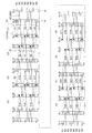
図1および図2に、部分巻線としてのU1相とU2相とを直列に接続してU相巻線を構成する場合のセグメント22の配置例を示す。図1はU1相の配置であり、図2はU2相の配置である。また、図3および図4に部分巻線としてのU1相からU4相を並列に接続してU相巻線を構成する場合のセグメント22の配置例を示す。図3はU1相およびU2相の配置であり、図4はU3相およびU4相の配置である。なお、V相巻線およびW相巻線については、セグメント22を挿入するスロット14の周方向の位置が異なる点を除きU相巻線と概ね同様の構成であるため、詳しい説明は省略する。
本実施例では、セグメント22として、一本の導体素線(平角線)の両側を曲げてヘアピン状に形成されたものを用いる。このセグメント22の両端はそれぞれ異なるスロット14に挿入され、セグメント22のステータコア12から突出した部分(以下、先端部)は曲げられて、例えば他のセグメント22のステータコア12から突出した先端部、U相端子、又は中性点N等と接続される。
図1から図4では、各セグメント22の頭部側を実線で示し、各セグメント22の脚部側(接続側)を破線で示している。図1から図4において、Saはセグメント22を区別するための符号であって接続される順番にa=1,2,…,64としており、例えば1番目のセグメント22はS1と表示している。また、SLbはスロット14を区別するための符号であって周方向に沿って順番にb=1,2,…,48(図7参照)としており、例えば1番目のスロット14はSL1と表示している。また、Ncはスロット14内でセグメント22が収納(挿入)される位置を区別するための符号(以下、導体番号)であって外径側から順番にc=1,2,…,8としている。また、Cdは同心状に巻回された複数のセグメント22からなる単位コイル21を区別するための符号であって接続される順番にd=1,2,…,16としており、例えば1番目の単位コイル21はC1と表示している。なお、単位コイル21はステータコア12の周方向に2n個(ただし、nは1以上の自然数。本実施例ではn=8)配置される。
また、図1から図4中、白丸はセグメント22のU相端子側、黒丸はセグメント22の中性点N(図5,6参照)側を示している。また、U相端子に接続されるセグメント22が収納されるスロット14の位置にはドットを付し、中性点Nに接続されるセグメント22が収納されるスロット14の位置には斜線を付している。
図1から図4に示すように、本実施例において単位コイル21は、二種類のセグメント22(第一のセグメント22A,第二のセグメント22B)が、径方向に交互に且つ同心状に配置されて構成されている。第一のセグメント22Aは、その両端が5スロット間隔でスロット14に挿入されるように形成されている。第二のセグメント22Bは、その両端が7スロット間隔でスロット14に挿入されるように形成されている。
より具体的には、図1および図3に示すように、jを0から(n/2-1)までの自然数(本実施例では、j=0,1,2,3)として、(1+2j)番目の単位コイル21は、(1+8j)番目、(2+8j)番目、(3+8j)番目、(4+8j)番目、(5+8j)番目の五つのセグメント22からなる。
(1+8j)番目のセグメント22は第一のセグメント22Aであり、U相端子側が(2+12j)番目のスロット14の導体番号N1の位置に収納され、中性点N側が(7+12j)番目のスロット14の導体番号N1の位置に収納されている。(2+8j)番目のセグメント22は第二のセグメント22Bであり、U相端子側が(1+12j)番目のスロット14の導体番号N2の位置に収納され、中性点N側が(8+12j)番目のスロット14の導体番号N3の位置に収納されている。(3+8j)番目のセグメント22は第一のセグメント22Aであり、U相端子側が(2+12j)番目のスロット14の導体番号N4の位置に収納され、中性点N側が(7+12j)番目のスロット14の導体番号N5の位置に収納されている。(4+8j)番目のセグメント22は第二のセグメント22Bであり、U相端子側が(1+12j)番目のスロット14の導体番号N6の位置に収納され、中性点N側が(8+12j)番目のスロット14の導体番号N7の位置に収納されている。(5+8j)番目のセグメント22は第一のセグメント22Aであり、U相端子側が(2+12j)番目のスロット14の導体番号N8の位置に収納され、中性点N側が(7+12j)番目のスロット14の導体番号N8の位置に収納されている。
(1+2j)番目の単位コイル21では、図中破線で示すように、(1+8j)番目のセグメント22の中性点側と(2+8j)番目のセグメント22のU相端子側、(2+8j)番目のセグメント22の中性点側と(3+8j)番目のセグメント22のU相端子側、(3+8j)番目のセグメント22の中性点側と(4+8j)番目のセグメント22のU相端子側、(4+8j)番目のセグメント22の中性点側と(5+8j)番目のセグメント22のU相端子側とが接続されている。
また、(2+2j)番目の単位コイル21は、(6+8j)番目、(7+8j)番目、(8+8j)番目の三つのセグメント22からなる。
(6+8j)番目のセグメント22は第一のセグメント22Aであり、U相端子側が(13+12j)番目のスロット14の導体番号N7の位置に収納され、中性点N側が(8+12j)番目のスロット14の導体番号N6の位置に収納されている。(7+8j)番目のセグメント22は第二のセグメント22Bであり、U相端子側が(14+12j)番目のスロット14の導体番号N5の位置に収納され、中性点N側が(7+12j)番目のスロット14の導体番号N4の位置に収納されている。(8+8j)番目のセグメント22は第一のセグメント22Aであり、U相端子側が(13+12j)番目のスロット14の導体番号N3の位置に収納され、中性点N側が(8+12j)番目のスロット14の導体番号N2の位置に収納されている。
(2+2j)番目の単位コイル21では、図中破線で示すように、(6+8j)番目のセグメント22の中性点側と(7+8j)番目のセグメント22のU相端子側、(7+8j)番目のセグメント22の中性点側と(8+8j)番目のセグメント22のU相端子側とが接続されている。
ただし、8番目の単位コイル21では、30番目のセグメント22は第一のセグメント22Aであり、U相端子側が1番目のスロット14の導体番号N7の位置に収納され、中性点N側が44番目のスロット14の導体番号N6の位置に収納されている。31番目のセグメント22は第二のセグメント22Bであり、U相端子側が2番目のスロット14の導体番号N5の位置に収納され、中性点N側が43番目のスロット14の導体番号N4の位置に収納されている。32番目のセグメント22は第一のセグメント22Aであり、U相端子側が1番目のスロット14の導体番号N3の位置に収納され、中性点N側が44番目のスロット14の導体番号N2の位置に収納されている。
また、図2および図4に示すように、j=0,1,2,…,(n/2-1)(本実施例では、j=0,1,2,3)として、(9+2j)番目の単位コイル21は、(33+8j)番目、(34+8j)番目、(35+8j)番目、(36+8j)番目、(37+8j)番目の五つのセグメント22からなる。
(33+8j)番目のセグメント22は第二のセグメント22Bであり、U相端子側が(1+12j)番目のスロット14の導体番号N1の位置に収納され、中性点N側が(8+12j)番目のスロット14の導体番号N1の位置に収納されている。(34+8j)番目のセグメント22は第一のセグメント22Aであり、U相端子側が(2+12j)番目のスロット14の導体番号N2の位置に収納され、中性点N側が(7+12j)番目のスロット14の導体番号N3の位置に収納されている。(35+8j)番目のセグメント22は第二のセグメント22Bであり、U相端子側が(1+12j)番目のスロット14の導体番号N4の位置に収納され、中性点N側が(8+12j)番目のスロット14の導体番号N5の位置に収納されている。(36+8j)番目のセグメント22は第一のセグメント22Aであり、U相端子側が(2+12j)番目のスロット14の導体番号N6の位置に収納され、中性点N側が(7+12j)番目のスロット14の導体番号N7の位置に収納されている。(37+8j)番目のセグメント22は第二のセグメント22Bであり、U相端子側が(1+12j)番目のスロット14の導体番号N8の位置に収納され、中性点N側が(8+12j)番目のスロット14の導体番号N8の位置に収納されている。
また、(10+2j)番目の単位コイル21は、(38+8j)番目、(39+8j)番目、(40+8j)番目の三つのセグメント22からなる。
(38+8j)番目のセグメント22は第二のセグメント22Bであり、U相端子側が(14+12j)番目のスロット14の導体番号N7の位置に収納され、中性点N側が(7+12j)番目のスロット14の導体番号N6の位置に収納されている。(39+8j)番目のセグメント22は第一のセグメント22Aであり、U相端子側が(13+12j)番目のスロット14の導体番号N5の位置に収納され、中性点N側が(8+12j)番目のスロット14の導体番号N4の位置に収納されている。(40+8j)番目のセグメント22は第二のセグメント22Bであり、U相端子側が(14+12j)番目のスロット14の導体番号N3の位置に収納され、中性点N側が(7+12j)番目のスロット14の導体番号N2の位置に収納されている。
ただし、16番目の単位コイル21では、62番目のセグメント22は第二のセグメント22Bであり、U相端子側が2番目のスロット14の導体番号N7の位置に収納され、中性点N側が43番目のスロット14の導体番号N6の位置に収納されている。63番目のセグメント22は第一のセグメント22Aであり、U相端子側が1番目のスロット14の導体番号N5の位置に収納され、中性点N側が44番目のスロット14の導体番号N4の位置に収納されている。64番目のセグメント22は第二のセグメント22Bであり、U相端子側が2番目のスロット14の導体番号N3の位置に収納され、中性点N側が43番目のスロット14の導体番号N2の位置に収納されている。
すなわち、本実施例においては、各単位コイル21において、二つのスロット間隔を有するセグメント22(22Aおよび22B)を同心状にスロット14に配置することにより、一つの単位コイル21を構成するセグメント22が四つのスロット14に収容された状態となっている。
そして、1番目の単位コイル21を構成する第一のセグメント22Aの各相の端子側(以下、相端子側)が収納されるスロット14が、当該1番目の単位コイル21の一方に隣接するn番目の単位コイル21の第二のセグメント22B、(n+1)番目の単位コイル21の第一のセグメント22A、および当該(n+1)番目の単位コイル21の一方に隣接する2n番目の単位コイル21の第二のセグメント22Bの相端子側が収納されるスロット14と同じとなっている。
また、1番目の単位コイル21を構成する第二のセグメント22Bの相端子側が収納されるスロット14が、当該1番目の単位コイル21の一方に隣接するn番目の単位コイル21の第一のセグメント22A、(n+1)番目の単位コイル21の第二のセグメント22B、および当該(n+1)番目の単位コイル21の一方に隣接する2n番目の単位コイル21の第一のセグメント22Aの相端子側が収納されるスロット14と同じとなっている。
また、1番目の単位コイル21を構成する第一のセグメント22Aの中性点側が収納されるスロット14が、当該1番目の単位コイル21の他方に隣接する2番目の単位コイル21の第二のセグメント22B、(n+1)番目の単位コイル21の第一のセグメント22A、および当該(n+1)番目の単位コイル21の他方に隣接する(n+2)番目の単位コイル21の第二のセグメント22Bの中性点側が収納されるスロット14と同じとなっている。
また、1番目の単位コイル21を構成する第二のセグメント22Bの中性点側が収納されるスロット14が、当該1番目の単位コイル21の他方に隣接する2番目の単位コイル21の第一のセグメント22A、(n+1)番目の単位コイル21の第二のセグメント22B、および当該(n+1)番目の単位コイル21の他方に隣接する(n+2)番目の単位コイル21の第一のセグメント22Aの中性点側が収納されるスロット14と同じとなっている。
また、(1+2i)番目の単位コイル21(ただし、iは1から(n/2-1)までの自然数)を構成する第一のセグメント22Aの各相の端子側(以下、相端子側)が収納されるスロット14が、当該(1+2i)番目の単位コイル21の一方に隣接する2i番目の単位コイル21の第二のセグメント22B、(n+1+2i)番目の単位コイル21の第一のセグメント22A、および当該(n+1+2i)番目の単位コイル21の一方に隣接する(n+2i)番目の単位コイル21の第二のセグメント22Bの相端子側が収納されるスロット14と同じとなっている。
また、(1+2i)番目の単位コイル21を構成する第二のセグメント22Bの相端子側が収納されるスロット14が、当該(1+2i)番目の単位コイル21の一方に隣接する2i番目の単位コイル21の第一のセグメント22A、(n+1+2i)番目の単位コイル21の第二のセグメント22B、および当該(n+1+2i)番目の単位コイル21の一方に隣接する(n+2i)番目の単位コイル21の第一のセグメント22Aの相端子側が収納されるスロット14と同じとなっている。
また、(1+2i)番目の単位コイル21を構成する第一のセグメント22Aの中性点側が収納されるスロット14が、当該(1+2i)番目の単位コイル21の他方に隣接する(2+2i)番目の単位コイル21の第二のセグメント22B、(n+1+2i)番目の単位コイル21の第一のセグメント22A、および当該(n+1+2i)番目の単位コイル21の他方に隣接する(n+2+2i)番目の単位コイル21の第二のセグメント22Bの中性点側が収納されるスロット14と同じとなっている。
また、(1+2i)番目の単位コイル21を構成する第二のセグメント22Bの中性点側が収納されるスロット14が、当該(1+2i)番目の単位コイル21の他方に隣接する(2+2i)番目の単位コイル21の第一のセグメント22A、(n+1+2i)番目の単位コイル21の第二のセグメント22B、および当該(n+1+2i)番目の単位コイル21の他方に隣接する(n+2+2i)番目の単位コイル21の第一のセグメント22Aの中性点側が収納されるスロット14と同じとなっている。
このような本実施例の回転機の固定子では、図1および図2に示すように、5番目,8番目,13番目,16番目,21番目,24番目,29番目のセグメント22の中性点側と、6番目,9番目,14番目,17番目,22番目,25番目,30番目のセグメント22のU相端子側をそれぞれ接続することにより1~8番目の単位コイル21を直列に接続したものをU1相巻線、37番目,40番目,45番目,48番目,53番目,56番目,61番目のセグメント22の中性点側と、38番目,41番目,46番目,49番目,54番目,57番目,62番目のセグメント22のU相端子側をそれぞれ接続することにより9~16番目の単位コイル21を直列に接続したものをU2相巻線として、32番目のセグメント22の中性点N側の脚部と、33番目のセグメント22のU相端子側の脚部とを接続することにより、U1相巻線とU2相巻線とを直列に接続してなるU相巻線を作製することができる。
同様に、図5に示すようにV1相巻線とV2相巻線とを直列に接続してV相巻線を作製し、W1相巻線とW2相巻線とを直列に接続してW相巻線を作製し、U相巻線,V相巻線およびW相巻線をY結線により結線することでステータコイルを直列巻線構造とすることができる。
また、図3および図4に示すように、5番目,8番目,13番目のセグメント22の中性点側と、6番目,9番目,14番目のセグメント22のU相端子側をそれぞれ接続することにより1~4番目の単位コイル21を直列に接続したものをU1相巻線、21番目,24番目,29番目のセグメント22の中性点側と、22番目,25番目,30番目のセグメント22のU相端子側をそれぞれ接続することにより5~8番目の単位コイル21を直列に接続したものをU2相巻線、37番目,40番目,45番目のセグメント22の中性点側と、38番目,41番目,46番目のセグメント22のU相端子側をそれぞれ接続することにより9~12番目の単位コイル21を直列に接続したものをU3相巻線、53番目,56番目,61番目のセグメント22の中性点側と、54番目,57番目,62番目のセグメント22のU相端子側をそれぞれ接続することにより13~16番目の単位コイル21を直列に接続したものをU4相巻線として、1番目のセグメント22のU相端子側の脚部と、17番目のセグメント22のU相端子側の脚部と、33番目のセグメント22のU相端子側の脚部と、49番目のセグメント22のU相端子側の脚部とを接続する一方、16番目のセグメント22の中性点N側の脚部と、32番目のセグメント22の中性点N側の脚部と、48番目のセグメント22の中性点N側の脚部と、64番目のセグメント22の中性点N側の脚部とを接続することにより、U1~U4相巻線を並列に接続してなるU相巻線を作製することができる。
同様に、図6に示すようにV1~V4相巻線を並列に接続してV相巻線を作製し、W1~W4相巻線を並列に接続してW相巻線を作製し、U相巻線,V相巻線およびW相巻線をY結線により結線することでステータコイルを並列巻線構造とすることができる。
このように構成される本実施例に係る回転機の固定子によれば、相互に異なる複数のスロット間隔でセグメント22を径方向に交互に且つ同心状に配置して単位コイル21を形成することにより、第二のセグメント22Bの軸方向の内側に第一のセグメント22Aを配置することができるため、従来の単位コイルに比較して、セグメント22を密集させて単位コイル21を形成することができ、コイルエンドの小型化が可能となる。またコイルエンドを直接液冷する場合、セグメント22を密集させていることで冷媒をコイルエンド全体に十分に行き渡らせることが可能となり、冷却効果が向上する。
さらに、本実施例に係る回転機の固定子によれば、セグメント22の配置は同一であっても、各単位コイル21の接続関係を変更することで直列配線または並列配線を選択する(切り替える)ことができるため、回転機の端子電圧を容易に変更することが可能となり、利便性が向上する。また、並列巻線構造とした場合でも、循環電流の発生を防止することができる。
なお、本発明は上述した実施例に限定されるものではなく、各相の巻線を構成する単位コイル21の数や単位コイル21を構成するセグメント22の数、セグメント22のスロット間隔等は、本発明の趣旨を逸脱しない範囲で必要に応じて設定することができる。
10 回転電機固定子
12 ステータコア
14 スロット
20 U相巻線
21 単位コイル
22 セグメント
22A 第一のセグメント
22B 第二のセグメント
12 ステータコア
14 スロット
20 U相巻線
21 単位コイル
22 セグメント
22A 第一のセグメント
22B 第二のセグメント
Claims (6)
- 周方向に沿って設けられた複数のスロットを有するステータコアと、
平角線により構成され、前記スロットに収納されるセグメントと、
径方向に沿って配置された複数の前記セグメントからなる単位コイルを前記ステータコアの周方向に配置して形成される分布巻巻線と、
を備え、
前記単位コイルは、相互に異なる複数のスロット間隔で径方向に交互に且つ同心状に配置された前記セグメントを接続して形成される
ことを特徴とする回転機の固定子。 - 前記単位コイルは、前記ステータコアの周方向に2n個(ただし、nは1以上の自然数)配置され、
前記分布巻巻線は、巻き始めの前記単位コイルを1番目のコイルとし、巻き終わりの前記単位コイルを2n番目のコイルとして、
1番目のコイルを構成する前記セグメントが収納される二つの前記スロットが、n番目のコイル、(n+1)番目のコイルおよび前記2n番目のコイルをそれぞれ構成する前記セグメントが収納される二つの前記スロットと同じであり、
前記1番目のコイルを構成する前記セグメントが収納される他の二つの前記スロットが、2番目のコイル、前記(n+1)番目のコイルおよび(n+2)番目のコイルをそれぞれ構成する前記セグメントが収納される二つの前記スロットと同じであり、
(1+2i)番目のコイル(ただし、iは1から(n/2-1)までの自然数)を構成する前記セグメントが収納される二つの前記スロットが、2i番目のコイル、(n+2i)番目のコイルおよび(n+1+2i)番目のコイルをそれぞれ構成する前記セグメントが収納される二つの前記スロットと同じであり、
前記(1+2i)番目のコイルを構成する前記セグメントが収納される他の二つの前記スロットが、(2+2i)番目のコイル、前記(n+1+2i)番目のコイルおよび(n+2+2i)番目のコイルをそれぞれ構成する前記セグメントが収納される二つの前記スロットと同じである
ことを特徴とする請求項1記載の回転機の固定子。 - 前記セグメントは、第一のスロット間隔を有する第一のセグメントと、前記第一のスロット間隔よりも大きい第二のスロット間隔を有する第二のセグメントとを含み、
前記単位コイルは、前記第一のセグメントと前記第二のセグメントとを径方向に交互に且つ同心状に配置して形成され、
前記1番目のコイルを構成する前記第一のセグメントの相端子側が収納される前記スロットが、前記n番目のコイルを構成する前記第二のセグメント、前記(n+1)番目のコイルを構成する前記第一のセグメントおよび前記2n番目のコイルを構成する前記第二のセグメントの相端子側が収納される前記スロットと同じであり、
前記1番目のコイルを構成する前記第二のセグメントの相端子側が収納される前記スロットが、前記n番目のコイルを構成する前記第一のセグメント、前記(n+1)番目のコイルを構成する前記第二のセグメントおよび前記2n番目のコイルを構成する前記第一のセグメントの相端子側が収納される前記スロットと同じであり、
前記1番目のコイルを構成する前記第一のセグメントの中性点側が収納される前記スロットが、前記2番目のコイルを構成する前記第二のセグメント、前記(n+1)番目のコイルを構成する前記第一のセグメントおよび前記(n+2)番目のコイルを構成する前記第二のセグメントの中性点側が収納される前記スロットと同じであり、
前記1番目のコイルを構成する前記第二のセグメントの中性点側が収納される前記スロットが、前記2番目のコイルを構成する前記第一のセグメント、前記(n+1)番目のコイルを構成する前記第二のセグメントおよび前記(n+2)番目のコイルを構成する前記第一のセグメントの中性点側が収納される前記スロットと同じであり、
前記(1+2i)番目のコイルを構成する前記第一のセグメントの相端子側が収納される前記スロットが、前記2i番目のコイルを構成する前記第二のセグメント、前記(n+1+2i)番目のコイルを構成する前記第一のセグメントおよび前記(n+2i)番目のコイルを構成する前記第二のセグメントの相端子側が収納される前記スロットと同じであり、
前記(1+2i)番目のコイルを構成する前記第二のセグメントの相端子側が収納される前記スロットが、前記2i番目のコイルを構成する前記第一のセグメント、前記(n+1+2i)番目のコイルを構成する前記第二のセグメントおよび前記(n+2i)番目のコイルを構成する前記第一のセグメントの相端子側が収納される前記スロットと同じであり、
前記(1+2i)番目のコイルを構成する前記第一のセグメントの中性点側が収納される前記スロットが、前記(2+2i)番目のコイルを構成する前記第二のセグメント、前記(n+1+2i)番目のコイルを構成する前記第一のセグメントおよび前記(n+2+2i)番目のコイルを構成する前記第二のセグメントの中性点側が収納される前記スロットと同じであり、
前記(1+2i)番目のコイルを構成する前記第二のセグメントの中性点側が収納される前記スロットが、前記(2+2i)番目のコイルを構成する前記第一のセグメント、前記(n+1+2i)番目のコイルを構成する前記第二のセグメントおよび前記(n+2+2i)番目のコイルを構成する前記第一のセグメントの中性点側が収納される前記スロットと同じである
ことを特徴とする請求項2記載の回転機の固定子。 - 前記単位コイルを前記ステータコアの周方向にn個ごとに直列に接続してなる各相の単位巻線を、直列に接続してなる
ことを特徴とする請求項1から請求項3のいずれか1項に記載の回転機の固定子。 - 前記単位コイルを前記ステータコアの周方向に(n/2)個ごとに直列に接続してなる各相の単位巻線を、並列に接続してなる
ことを特徴とする請求項1から請求項3のいずれか1項に記載の回転機の固定子。 - 前記セグメントは、一本の平角線の両端を曲げてヘアピン状に形成されるとともに、両端が相互に異なる前記スロットに挿入され、
当該セグメントの前記ステータコアから突出して曲げられた先端部は、他の前記セグメントの前記先端部又は相端子又は中性点に接続されている
ことを特徴とする請求項1から請求項5のいずれか1項に記載の回転機の固定子。
Priority Applications (3)
| Application Number | Priority Date | Filing Date | Title |
|---|---|---|---|
| US16/954,264 US11056944B2 (en) | 2017-12-25 | 2018-11-16 | Stator of rotary machine |
| EP18894629.7A EP3731378B1 (en) | 2017-12-25 | 2018-11-16 | Stator for rotary machine |
| CN201880083740.2A CN111527671B (zh) | 2017-12-25 | 2018-11-16 | 旋转机的固定子 |
Applications Claiming Priority (2)
| Application Number | Priority Date | Filing Date | Title |
|---|---|---|---|
| JP2017-247241 | 2017-12-25 | ||
| JP2017247241A JP6508318B1 (ja) | 2017-12-25 | 2017-12-25 | 回転機の固定子 |
Publications (1)
| Publication Number | Publication Date |
|---|---|
| WO2019130893A1 true WO2019130893A1 (ja) | 2019-07-04 |
Family
ID=66429908
Family Applications (1)
| Application Number | Title | Priority Date | Filing Date |
|---|---|---|---|
| PCT/JP2018/042406 Ceased WO2019130893A1 (ja) | 2017-12-25 | 2018-11-16 | 回転機の固定子 |
Country Status (5)
| Country | Link |
|---|---|
| US (1) | US11056944B2 (ja) |
| EP (1) | EP3731378B1 (ja) |
| JP (1) | JP6508318B1 (ja) |
| CN (1) | CN111527671B (ja) |
| WO (1) | WO2019130893A1 (ja) |
Families Citing this family (4)
| Publication number | Priority date | Publication date | Assignee | Title |
|---|---|---|---|---|
| CN111373635B (zh) * | 2017-12-14 | 2022-07-12 | 株式会社爱信 | 定子 |
| JP7128702B2 (ja) * | 2018-09-25 | 2022-08-31 | 株式会社Soken | 回転電機 |
| DE102020213647A1 (de) | 2020-10-29 | 2022-05-05 | Valeo Siemens Eautomotive Germany Gmbh | Stator für eine elektrische Maschine und elektrische Maschine |
| DE102022203671A1 (de) | 2022-04-12 | 2023-10-12 | Volkswagen Aktiengesellschaft | Stator für eine dreiphasige Elektromaschine, Elektromaschine und Kraftfahrzeug mit Elektromaschine |
Citations (6)
| Publication number | Priority date | Publication date | Assignee | Title |
|---|---|---|---|---|
| JP2004023808A (ja) | 2002-06-12 | 2004-01-22 | Denso Corp | セグメント順次接合型ステータコイルを有する高電圧車両用回転電機 |
| JP2007151393A (ja) * | 2007-01-16 | 2007-06-14 | Denso Corp | 車両用タンデム式回転電機 |
| JP2012016195A (ja) | 2010-07-01 | 2012-01-19 | Toyota Motor Corp | 回転電機固定子 |
| WO2014184951A1 (ja) * | 2013-05-17 | 2014-11-20 | 三菱電機株式会社 | 回転電機の固定子 |
| JP2016013031A (ja) * | 2014-06-30 | 2016-01-21 | アイシン精機株式会社 | 回転電機 |
| WO2017110949A1 (ja) * | 2015-12-25 | 2017-06-29 | アイシン精機株式会社 | 回転電機およびその製造方法 |
Family Cites Families (23)
| Publication number | Priority date | Publication date | Assignee | Title |
|---|---|---|---|---|
| JP3494729B2 (ja) | 1995-01-24 | 2004-02-09 | 株式会社東芝 | 三相電機子巻線 |
| JP3515283B2 (ja) * | 1995-08-18 | 2004-04-05 | 株式会社東芝 | 回転電機の電機子巻線及びその製造方法 |
| DE10326095A1 (de) * | 2002-06-12 | 2004-04-15 | Denso Corp., Kariya | Spule aus sequentiell verbundenen Segmenten für eine rotierende elektrische Maschine |
| JP4715934B2 (ja) * | 2009-02-20 | 2011-07-06 | 株式会社デンソー | 5相モータ |
| JP5541585B2 (ja) * | 2010-12-28 | 2014-07-09 | 株式会社デンソー | 回転電機 |
| JP2012200101A (ja) * | 2011-03-23 | 2012-10-18 | Toyota Motor Corp | 回転電機ステータ及び回転電機ステータの製造方法 |
| JP5703918B2 (ja) * | 2011-04-08 | 2015-04-22 | トヨタ自動車株式会社 | 回転電機固定子 |
| JP5502913B2 (ja) * | 2012-01-23 | 2014-05-28 | 三菱電機株式会社 | 回転電機 |
| WO2013145976A1 (ja) * | 2012-03-29 | 2013-10-03 | 本田技研工業株式会社 | 回転電機のステータ構造 |
| DE112013003398T5 (de) * | 2012-07-06 | 2015-04-09 | Mitsubishi Electric Corporation | Drehende elektrische Maschine und Herstellungsverfahren für diese |
| DE112013003663B4 (de) * | 2012-07-26 | 2025-01-23 | Mitsubishi Electric Corporation | Elektrische Rotationsmaschine |
| JP5757282B2 (ja) * | 2012-11-07 | 2015-07-29 | 株式会社デンソー | 固定子および回転電機 |
| WO2014162626A1 (ja) * | 2013-04-02 | 2014-10-09 | 三菱電機株式会社 | 回転電機の固定子 |
| CN105794089B (zh) * | 2013-11-29 | 2018-06-26 | 三菱电机株式会社 | 电力机械的电枢 |
| CN105917555B (zh) * | 2014-01-17 | 2018-09-04 | 三菱电机株式会社 | 旋转电机 |
| WO2015145696A1 (ja) * | 2014-03-27 | 2015-10-01 | 株式会社小松製作所 | ステータ及びそれを備えた回転電機 |
| DE112015001564T5 (de) * | 2014-03-31 | 2017-02-16 | Honda Motor Co., Ltd. | Stator für elektrische rotierende Maschine |
| US20170054339A1 (en) * | 2014-04-24 | 2017-02-23 | Mitsubishi Electric Corporation | Stator of rotary electrical machine and rotary electrical machine using such stator |
| JP6156268B2 (ja) * | 2014-06-27 | 2017-07-05 | 株式会社デンソー | 回転電機の固定子 |
| JP6324521B2 (ja) * | 2014-09-22 | 2018-05-16 | 三菱電機株式会社 | 回転電機の固定子 |
| JP6235504B2 (ja) * | 2015-02-17 | 2017-11-22 | ファナック株式会社 | 分布巻のラジアルギャップ型モータおよびその巻線配置方法 |
| JP6173507B1 (ja) * | 2016-03-04 | 2017-08-02 | 三菱電機株式会社 | 回転電機の固定子およびその製造方法 |
| DE102018207231A1 (de) * | 2018-05-09 | 2019-11-14 | Volkswagen Aktiengesellschaft | Stator für eine elektrische Maschine, elektrische Maschine und Herstellungsverfahren für einen Stator für eine elektrische Maschine |
-
2017
- 2017-12-25 JP JP2017247241A patent/JP6508318B1/ja active Active
-
2018
- 2018-11-16 WO PCT/JP2018/042406 patent/WO2019130893A1/ja not_active Ceased
- 2018-11-16 EP EP18894629.7A patent/EP3731378B1/en active Active
- 2018-11-16 CN CN201880083740.2A patent/CN111527671B/zh active Active
- 2018-11-16 US US16/954,264 patent/US11056944B2/en active Active
Patent Citations (6)
| Publication number | Priority date | Publication date | Assignee | Title |
|---|---|---|---|---|
| JP2004023808A (ja) | 2002-06-12 | 2004-01-22 | Denso Corp | セグメント順次接合型ステータコイルを有する高電圧車両用回転電機 |
| JP2007151393A (ja) * | 2007-01-16 | 2007-06-14 | Denso Corp | 車両用タンデム式回転電機 |
| JP2012016195A (ja) | 2010-07-01 | 2012-01-19 | Toyota Motor Corp | 回転電機固定子 |
| WO2014184951A1 (ja) * | 2013-05-17 | 2014-11-20 | 三菱電機株式会社 | 回転電機の固定子 |
| JP2016013031A (ja) * | 2014-06-30 | 2016-01-21 | アイシン精機株式会社 | 回転電機 |
| WO2017110949A1 (ja) * | 2015-12-25 | 2017-06-29 | アイシン精機株式会社 | 回転電機およびその製造方法 |
Non-Patent Citations (1)
| Title |
|---|
| See also references of EP3731378A4 |
Also Published As
| Publication number | Publication date |
|---|---|
| EP3731378A4 (en) | 2021-01-20 |
| EP3731378B1 (en) | 2022-06-08 |
| US20200395805A1 (en) | 2020-12-17 |
| CN111527671B (zh) | 2021-07-16 |
| US11056944B2 (en) | 2021-07-06 |
| EP3731378A1 (en) | 2020-10-28 |
| JP6508318B1 (ja) | 2019-05-08 |
| JP2019115180A (ja) | 2019-07-11 |
| CN111527671A (zh) | 2020-08-11 |
Similar Documents
| Publication | Publication Date | Title |
|---|---|---|
| JP6508318B1 (ja) | 回転機の固定子 | |
| JP6029548B2 (ja) | 回転電機 | |
| JP2009524384A (ja) | 3相巻線系を有する電気機械 | |
| JP7070075B2 (ja) | 回転電機 | |
| JP2015023670A (ja) | 回転電機のコイル構造 | |
| JP2015035837A (ja) | 回転電機、及び回転電機の製造方法 | |
| JP2016152730A (ja) | 3相交流電動機 | |
| US7064470B2 (en) | Three-phase motor | |
| WO2013140508A1 (ja) | 車両用回転電機の固定子およびその製造方法 | |
| WO2015019778A1 (ja) | 回転電機の固定子巻線、回転電機の固定子、回転電機の固定子の製造方法、及び回転電機の固定子の製造に用いる治具 | |
| WO2015162643A1 (ja) | 回転電機の固定子及びこの固定子を用いた回転電機 | |
| JP2009033832A (ja) | モータ用ステータ | |
| JP2010081771A (ja) | ステータ | |
| CN106849435A (zh) | 旋转电机 | |
| JP2010268575A (ja) | 回転電機 | |
| JP7806652B2 (ja) | 回転電機用ステータ | |
| CN112953069B (zh) | 旋转电机 | |
| JP6295657B2 (ja) | 3相回転電機の波巻き巻線 | |
| CN210327195U (zh) | 一种电机绕组及电机定子 | |
| KR20230044642A (ko) | 고정자 및 그 고정자를 포함하는 모터 | |
| CN105471147A (zh) | 旋转电机以及旋转电机的制造方法 | |
| CN213547206U (zh) | 一种电机定子及电机 | |
| JP2021093835A (ja) | 回転電機 | |
| CN214124962U (zh) | 一种电机定子及电机 | |
| JP2014143828A (ja) | 回転電機の波巻き巻線 |
Legal Events
| Date | Code | Title | Description |
|---|---|---|---|
| 121 | Ep: the epo has been informed by wipo that ep was designated in this application |
Ref document number: 18894629 Country of ref document: EP Kind code of ref document: A1 |
|
| NENP | Non-entry into the national phase |
Ref country code: DE |
|
| ENP | Entry into the national phase |
Ref document number: 2018894629 Country of ref document: EP Effective date: 20200721 |