WO2019130970A1 - 冷却装置、半導体製造装置および半導体製造方法 - Google Patents
冷却装置、半導体製造装置および半導体製造方法 Download PDFInfo
- Publication number
- WO2019130970A1 WO2019130970A1 PCT/JP2018/043987 JP2018043987W WO2019130970A1 WO 2019130970 A1 WO2019130970 A1 WO 2019130970A1 JP 2018043987 W JP2018043987 W JP 2018043987W WO 2019130970 A1 WO2019130970 A1 WO 2019130970A1
- Authority
- WO
- WIPO (PCT)
- Prior art keywords
- tank
- cooling device
- path
- refrigerant
- heat
- Prior art date
- Legal status (The legal status is an assumption and is not a legal conclusion. Google has not performed a legal analysis and makes no representation as to the accuracy of the status listed.)
- Ceased
Links
Images


Classifications
-
- F—MECHANICAL ENGINEERING; LIGHTING; HEATING; WEAPONS; BLASTING
- F25—REFRIGERATION OR COOLING; COMBINED HEATING AND REFRIGERATION SYSTEMS; HEAT PUMP SYSTEMS; MANUFACTURE OR STORAGE OF ICE; LIQUEFACTION SOLIDIFICATION OF GASES
- F25B—REFRIGERATION MACHINES, PLANTS OR SYSTEMS; COMBINED HEATING AND REFRIGERATION SYSTEMS; HEAT PUMP SYSTEMS
- F25B23/00—Machines, plants or systems, with a single mode of operation not covered by groups F25B1/00 - F25B21/00, e.g. using selective radiation effect
- F25B23/006—Machines, plants or systems, with a single mode of operation not covered by groups F25B1/00 - F25B21/00, e.g. using selective radiation effect boiling cooling systems
-
- G—PHYSICS
- G03—PHOTOGRAPHY; CINEMATOGRAPHY; ANALOGOUS TECHNIQUES USING WAVES OTHER THAN OPTICAL WAVES; ELECTROGRAPHY; HOLOGRAPHY
- G03F—PHOTOMECHANICAL PRODUCTION OF TEXTURED OR PATTERNED SURFACES, e.g. FOR PRINTING, FOR PROCESSING OF SEMICONDUCTOR DEVICES; MATERIALS THEREFOR; ORIGINALS THEREFOR; APPARATUS SPECIALLY ADAPTED THEREFOR
- G03F7/00—Photomechanical, e.g. photolithographic, production of textured or patterned surfaces, e.g. printing surfaces; Materials therefor, e.g. comprising photoresists; Apparatus specially adapted therefor
- G03F7/70—Microphotolithographic exposure; Apparatus therefor
- G03F7/708—Construction of apparatus, e.g. environment aspects, hygiene aspects or materials
- G03F7/70858—Environment aspects, e.g. pressure of beam-path gas, temperature
- G03F7/70866—Environment aspects, e.g. pressure of beam-path gas, temperature of mask or workpiece
- G03F7/70875—Temperature, e.g. temperature control of masks or workpieces via control of stage temperature
-
- C—CHEMISTRY; METALLURGY
- C23—COATING METALLIC MATERIAL; COATING MATERIAL WITH METALLIC MATERIAL; CHEMICAL SURFACE TREATMENT; DIFFUSION TREATMENT OF METALLIC MATERIAL; COATING BY VACUUM EVAPORATION, BY SPUTTERING, BY ION IMPLANTATION OR BY CHEMICAL VAPOUR DEPOSITION, IN GENERAL; INHIBITING CORROSION OF METALLIC MATERIAL OR INCRUSTATION IN GENERAL
- C23C—COATING METALLIC MATERIAL; COATING MATERIAL WITH METALLIC MATERIAL; SURFACE TREATMENT OF METALLIC MATERIAL BY DIFFUSION INTO THE SURFACE, BY CHEMICAL CONVERSION OR SUBSTITUTION; COATING BY VACUUM EVAPORATION, BY SPUTTERING, BY ION IMPLANTATION OR BY CHEMICAL VAPOUR DEPOSITION, IN GENERAL
- C23C14/00—Coating by vacuum evaporation, by sputtering or by ion implantation of the coating forming material
- C23C14/22—Coating by vacuum evaporation, by sputtering or by ion implantation of the coating forming material characterised by the process of coating
- C23C14/54—Controlling or regulating the coating process
- C23C14/541—Heating or cooling of the substrates
-
- C—CHEMISTRY; METALLURGY
- C23—COATING METALLIC MATERIAL; COATING MATERIAL WITH METALLIC MATERIAL; CHEMICAL SURFACE TREATMENT; DIFFUSION TREATMENT OF METALLIC MATERIAL; COATING BY VACUUM EVAPORATION, BY SPUTTERING, BY ION IMPLANTATION OR BY CHEMICAL VAPOUR DEPOSITION, IN GENERAL; INHIBITING CORROSION OF METALLIC MATERIAL OR INCRUSTATION IN GENERAL
- C23C—COATING METALLIC MATERIAL; COATING MATERIAL WITH METALLIC MATERIAL; SURFACE TREATMENT OF METALLIC MATERIAL BY DIFFUSION INTO THE SURFACE, BY CHEMICAL CONVERSION OR SUBSTITUTION; COATING BY VACUUM EVAPORATION, BY SPUTTERING, BY ION IMPLANTATION OR BY CHEMICAL VAPOUR DEPOSITION, IN GENERAL
- C23C16/00—Chemical coating by decomposition of gaseous compounds, without leaving reaction products of surface material in the coating, i.e. chemical vapour deposition [CVD] processes
- C23C16/44—Chemical coating by decomposition of gaseous compounds, without leaving reaction products of surface material in the coating, i.e. chemical vapour deposition [CVD] processes characterised by the method of coating
- C23C16/46—Chemical coating by decomposition of gaseous compounds, without leaving reaction products of surface material in the coating, i.e. chemical vapour deposition [CVD] processes characterised by the method of coating characterised by the method used for heating the substrate
- C23C16/463—Cooling of the substrate
-
- F—MECHANICAL ENGINEERING; LIGHTING; HEATING; WEAPONS; BLASTING
- F25—REFRIGERATION OR COOLING; COMBINED HEATING AND REFRIGERATION SYSTEMS; HEAT PUMP SYSTEMS; MANUFACTURE OR STORAGE OF ICE; LIQUEFACTION SOLIDIFICATION OF GASES
- F25B—REFRIGERATION MACHINES, PLANTS OR SYSTEMS; COMBINED HEATING AND REFRIGERATION SYSTEMS; HEAT PUMP SYSTEMS
- F25B29/00—Combined heating and refrigeration systems, e.g. operating alternately or simultaneously
-
- F—MECHANICAL ENGINEERING; LIGHTING; HEATING; WEAPONS; BLASTING
- F25—REFRIGERATION OR COOLING; COMBINED HEATING AND REFRIGERATION SYSTEMS; HEAT PUMP SYSTEMS; MANUFACTURE OR STORAGE OF ICE; LIQUEFACTION SOLIDIFICATION OF GASES
- F25D—REFRIGERATORS; COLD ROOMS; ICE-BOXES; COOLING OR FREEZING APPARATUS NOT OTHERWISE PROVIDED FOR
- F25D17/00—Arrangements for circulating cooling fluids; Arrangements for circulating gas, e.g. air, within refrigerated spaces
- F25D17/02—Arrangements for circulating cooling fluids; Arrangements for circulating gas, e.g. air, within refrigerated spaces for circulating liquids, e.g. brine
-
- G—PHYSICS
- G03—PHOTOGRAPHY; CINEMATOGRAPHY; ANALOGOUS TECHNIQUES USING WAVES OTHER THAN OPTICAL WAVES; ELECTROGRAPHY; HOLOGRAPHY
- G03F—PHOTOMECHANICAL PRODUCTION OF TEXTURED OR PATTERNED SURFACES, e.g. FOR PRINTING, FOR PROCESSING OF SEMICONDUCTOR DEVICES; MATERIALS THEREFOR; ORIGINALS THEREFOR; APPARATUS SPECIALLY ADAPTED THEREFOR
- G03F7/00—Photomechanical, e.g. photolithographic, production of textured or patterned surfaces, e.g. printing surfaces; Materials therefor, e.g. comprising photoresists; Apparatus specially adapted therefor
- G03F7/0002—Lithographic processes using patterning methods other than those involving the exposure to radiation, e.g. by stamping
-
- G—PHYSICS
- G03—PHOTOGRAPHY; CINEMATOGRAPHY; ANALOGOUS TECHNIQUES USING WAVES OTHER THAN OPTICAL WAVES; ELECTROGRAPHY; HOLOGRAPHY
- G03F—PHOTOMECHANICAL PRODUCTION OF TEXTURED OR PATTERNED SURFACES, e.g. FOR PRINTING, FOR PROCESSING OF SEMICONDUCTOR DEVICES; MATERIALS THEREFOR; ORIGINALS THEREFOR; APPARATUS SPECIALLY ADAPTED THEREFOR
- G03F7/00—Photomechanical, e.g. photolithographic, production of textured or patterned surfaces, e.g. printing surfaces; Materials therefor, e.g. comprising photoresists; Apparatus specially adapted therefor
- G03F7/70—Microphotolithographic exposure; Apparatus therefor
- G03F7/70691—Handling of masks or workpieces
- G03F7/70758—Drive means, e.g. actuators, motors for long- or short-stroke modules or fine or coarse driving
-
- G—PHYSICS
- G03—PHOTOGRAPHY; CINEMATOGRAPHY; ANALOGOUS TECHNIQUES USING WAVES OTHER THAN OPTICAL WAVES; ELECTROGRAPHY; HOLOGRAPHY
- G03F—PHOTOMECHANICAL PRODUCTION OF TEXTURED OR PATTERNED SURFACES, e.g. FOR PRINTING, FOR PROCESSING OF SEMICONDUCTOR DEVICES; MATERIALS THEREFOR; ORIGINALS THEREFOR; APPARATUS SPECIALLY ADAPTED THEREFOR
- G03F7/00—Photomechanical, e.g. photolithographic, production of textured or patterned surfaces, e.g. printing surfaces; Materials therefor, e.g. comprising photoresists; Apparatus specially adapted therefor
- G03F7/70—Microphotolithographic exposure; Apparatus therefor
- G03F7/708—Construction of apparatus, e.g. environment aspects, hygiene aspects or materials
- G03F7/70858—Environment aspects, e.g. pressure of beam-path gas, temperature
-
- H—ELECTRICITY
- H01—ELECTRIC ELEMENTS
- H01J—ELECTRIC DISCHARGE TUBES OR DISCHARGE LAMPS
- H01J37/00—Discharge tubes with provision for introducing objects or material to be exposed to the discharge, e.g. for the purpose of examination or processing thereof
- H01J37/32—Gas-filled discharge tubes
- H01J37/32431—Constructional details of the reactor
- H01J37/32458—Vessel
- H01J37/32522—Temperature
-
- H—ELECTRICITY
- H10—SEMICONDUCTOR DEVICES; ELECTRIC SOLID-STATE DEVICES NOT OTHERWISE PROVIDED FOR
- H10P—GENERIC PROCESSES OR APPARATUS FOR THE MANUFACTURE OR TREATMENT OF DEVICES COVERED BY CLASS H10
- H10P72/00—Handling or holding of wafers, substrates or devices during manufacture or treatment thereof
- H10P72/70—Handling or holding of wafers, substrates or devices during manufacture or treatment thereof for supporting or gripping
-
- H—ELECTRICITY
- H10—SEMICONDUCTOR DEVICES; ELECTRIC SOLID-STATE DEVICES NOT OTHERWISE PROVIDED FOR
- H10P—GENERIC PROCESSES OR APPARATUS FOR THE MANUFACTURE OR TREATMENT OF DEVICES COVERED BY CLASS H10
- H10P76/00—Manufacture or treatment of masks on semiconductor bodies, e.g. by lithography or photolithography
-
- H—ELECTRICITY
- H10—SEMICONDUCTOR DEVICES; ELECTRIC SOLID-STATE DEVICES NOT OTHERWISE PROVIDED FOR
- H10P—GENERIC PROCESSES OR APPARATUS FOR THE MANUFACTURE OR TREATMENT OF DEVICES COVERED BY CLASS H10
- H10P72/00—Handling or holding of wafers, substrates or devices during manufacture or treatment thereof
- H10P72/04—Apparatus for manufacture or treatment
- H10P72/0402—Apparatus for fluid treatment
-
- H—ELECTRICITY
- H10—SEMICONDUCTOR DEVICES; ELECTRIC SOLID-STATE DEVICES NOT OTHERWISE PROVIDED FOR
- H10P—GENERIC PROCESSES OR APPARATUS FOR THE MANUFACTURE OR TREATMENT OF DEVICES COVERED BY CLASS H10
- H10P72/00—Handling or holding of wafers, substrates or devices during manufacture or treatment thereof
- H10P72/04—Apparatus for manufacture or treatment
- H10P72/0431—Apparatus for thermal treatment
- H10P72/0434—Apparatus for thermal treatment mainly by convection
Definitions
- the present invention relates to a cooling device, a semiconductor manufacturing apparatus, and a semiconductor manufacturing method.
- a semiconductor manufacturing apparatus such as a pattern forming apparatus such as an exposure apparatus, an imprint apparatus, or an electron beam drawing apparatus, or a plasma processing apparatus such as a CVD apparatus, an etching apparatus, or a sputtering apparatus is heated by a drive mechanism or plasma. It may have a heat generating part such as a member.
- the semiconductor manufacturing apparatus may be equipped with a cooling device to cool such a heat generating part. The cooling device takes heat from the heat generating part and cools the heat generating part by transferring the heat.
- Japanese Patent No. 5313384 describes a cooling system comprising an evaporator for extracting heat from parts, a condenser, a pump, an accumulator, a heat exchanger, and a temperature sensor.
- a circuit is formed in which the fluid exiting the pump returns to the pump via the evaporator and the condenser, and the accumulator is in fluid communication with the circuit.
- the heat exchanger transfers heat from the fluid in the accumulator and transfers heat to the fluid in the accumulator. This amount is controlled based on the output of the temperature sensor.
- the heat generating part In the heat generating part, vaporization cooling is not performed until the temperature rises to the boiling point under the fluid pressure of the heat generating part, so the temperature fluctuation of the heat generating part is allowed during this time, and the members around the heat generating part are thermally expanded. It can be deformed. Therefore, in order to suppress temperature fluctuations, the gas-liquid balance of the fluid is changed by controlling the amount of heat to the accumulator so that the temperature downstream of the heat generating part reaches a predetermined temperature using the gas-liquid two-phase accumulator, the pressure of the entire system The boiling point is controlled by changing.
- One aspect of the present invention provides a cooling device having a simple configuration.
- One aspect of the present invention relates to a cooling device, wherein the cooling device circulates a liquid phase refrigerant such that the liquid phase refrigerant is extracted from the tank, cooled, and returned to the tank.
- a heater configured to heat the refrigerant in the liquid phase supplied from the first path; and a second path branched from the first path, the second path being heated by the heater
- a throttling for reducing the pressure of the refrigerant, and a vaporizer for vaporizing at least a part of the refrigerant having passed the throttling by heat from the object to be cooled, the refrigerant having passed the vaporizer is returned to the tank.
- the structure of the cooling device 1 of 1st Embodiment of this invention is shown by FIG.
- the object to be cooled by the cooling device 1 is not limited to a particular object, but may be, for example, a semiconductor manufacturing apparatus, in particular, a heat generating portion of the semiconductor manufacturing apparatus.
- the semiconductor manufacturing apparatus may be, for example, a pattern forming apparatus such as an exposure apparatus, an imprint apparatus, or a charged particle beam drawing apparatus, or a plasma processing apparatus such as a CVD apparatus, an etching apparatus, or a sputtering apparatus.
- the pattern forming apparatus has a drive mechanism that moves parts such as a substrate and / or an original plate at high speed, and the drive mechanism generates heat as the article is driven, and can become a heat generating portion.
- parts such as electrodes are heated by plasma, and the parts can be heat generating parts.
- the cooling device 1 can be configured to cool an object to be cooled 80 such as a heat generating portion.
- the cooling device 1 includes a tank 10 and a first path 20 for circulating the liquid phase refrigerant 12 by the pump 22 so as to take out the liquid phase refrigerant 12 from the tank 10, cool it with the heat exchanger 26, and return it to the tank 10. And a second path 30 branched from the first path 20.
- a branch point P1 of the second path 30 from the first path 20 may be disposed between the pump 22 and the heat exchanger 26.
- the first passage 20 may have a first throttle 24 disposed between the heat exchanger 26 and the tank 10.
- the first throttle 24 can lower the pressure of the liquid phase refrigerant 12.
- the first throttle 24 may be disposed between the heat exchanger 26 and the branch point P1 of the second path 30 from the first path 20.
- the refrigerant 12 may be circulated in the liquid phase. Therefore, it is not necessary to consider that the pump is damaged by cavitation as in a system in which liquid and gas phases are mixed. Therefore, according to the first embodiment, there is no need to provide a condenser for changing the gas phase refrigerant 12 to the liquid phase in the first path 20, and the cooling device 1 having a simple configuration can be realized. However, in the design of the first path 20, the specifications and the like of the pump 22 may be determined such that the occurrence of cavitation in the transfer of the liquid phase refrigerant 12 is prevented.
- the pressure of the refrigerant 12 is the sum of the saturated vapor pressure at the temperature of the suction portion of the refrigerant 12 and NPSH (abbreviation of Net Positive Suction Head) specific to the pump 22.
- NPSH abbreviation of Net Positive Suction Head
- the second path 30 may include, for example, a heater 32, a throttle (second throttle) 34, and a vaporizer 36, and may be configured to return the refrigerant that has passed through the vaporizer 36 to the tank 10.
- the heater 32 heats the liquid phase refrigerant 12 supplied from the first path 20 to a predetermined temperature.
- the throttling 32 lowers the pressure of the refrigerant 12 heated to a predetermined temperature by the heater 32 to near the saturated vapor pressure at the predetermined temperature, and makes the refrigerant 12 easily boil.
- the vaporizer 36 boils and vaporizes at least a part of the refrigerant 12 which has passed through the throttle 34 by the heat from the object to be cooled 80.
- the refrigerant 12 in the gas-liquid two-phase mixed state that has passed through the vaporizer 36 is returned to the tank 10, is cooled by mixing with the refrigerant 12 in the liquid phase cooled in the first passage 20, and changes from gas phase to liquid phase It can (ie, condense).
- the cooling device 1 can further include a temperature detector 42 that detects the temperature of the refrigerant 12 that has passed through the throttle 34, and a temperature controller 44 that controls the heater 32 based on the output of the temperature detector 42.
- the refrigerant 12 set to the target temperature can be supplied to the vaporizer 36.
- the phase change of the refrigerant 12 is limited to two places of the vaporizer 36 and the tank 10, and further, the refrigerant 12 of the liquid phase is condensed by the mixture of the refrigerants 12 having different temperature differences.
- the means for discharging the heat recovered by the cooling device 1 out of the system may be one of the heat exchangers 26.
- the cooling device 1 with a simple configuration can be realized.
- the cooling device 1 of 2nd Embodiment is an improvement of the cooling device 1 of the first embodiment, and matters not mentioned as the second embodiment can follow the first embodiment.
- the cooling device 1 according to the second embodiment includes a detection unit 52 that detects the amount of vaporized refrigerant 12 in the tank 10, and a controller 54 that controls (heat exchange with) the heat exchanger 26 based on the output of the detection unit 52. And can be additionally provided.
- the amount of vaporized refrigerant 12 in the tank 10 depends on the pressure in the tank 10. Therefore, the detection unit 52 can detect the amount of the vaporized refrigerant 12 in the tank 10 by detecting the pressure in the tank 10.
- the amount of vaporized refrigerant 12 in the tank 10 (in other words, the pressure in the tank 10) also depends on the temperature of the liquid phase refrigerant 12 in the tank 10. Therefore, the temperature of the liquid phase refrigerant 12 circulating in the first path 20 can be controlled by the controller 54 controlling (the heat exchange in) the heat exchanger 26 based on the output of the detection unit 52, Furthermore, the amount of condensation of the vaporized refrigerant 12 can be controlled.
- the gas phase refrigerant 12 In order to control the amount of condensation of the refrigerant 12, the gas phase refrigerant 12 must always be present inside the tank 10. In order to achieve this, the tank 10 can be filled with a gas 72 that does not condense under the temperature of the tank 10.
- the gas 72 is a gas that does not react with the refrigerant 12.
- FIG. 3 is a phase diagram of the refrigerant 12 in the cooling device 1.
- a saturated vapor pressure line and a thermal cycle are exemplified.
- the refrigerant 12 is in the liquid phase above the saturated vapor pressure line, and the refrigerant 12 is in the vapor phase below the saturated vapor pressure line.
- the liquid phase refrigerant 12 is sucked from the tank 10 by the pump 22 and pressurized to be in the state S2, cooled by the heat exchanger 26 to be in the state S5, and further decompressed by the throttle 24 It is returned to the tank 10 in the state S6.
- the refrigerant 12 in the state S2 is heated by the heater 32 to be in the state S3, and then decompressed by the throttle 34 to be in the state S4 and returned to the tank 10 through the vaporizer 36.
- the gas 72 is a partial pressure ("gas partial pressure") corresponding to the difference between the vapor pressure of the refrigerant 12 returned to the tank 10 and the vapor pressure of the liquid phase refrigerant 12 (temperature controlled) in the tank 10 A predetermined amount is enclosed in the tank 10 to give.
- the refrigerant 12 returned to the tank 10 through the second path 30 can exist as a gas having a saturated vapor pressure at the temperature of the state S1.
- the refrigerant 12 will be in the state above the saturated vapor pressure line in the state S1, that is, in the liquid phase.
- Making the partial pressure of the gas 72 equal to or higher than NPSH of the pump 22 is equivalent to preventing cavitation. Therefore, the partial pressure of the gas 72 may be equal to or higher than NPSH of the pump 22.
- the refrigerant 12 When the object to be cooled 80 generates heat, the refrigerant 12 is vaporized in the vaporizer 36 of the second path 30 to absorb heat as latent heat and is returned to the tank 10, and the pressure in the tank 10 rises.
- the amount of the increase is detected by the detector 52, and the controller 54 controls the pressure of the refrigerant 12 in the first path 20 so that the pressure of the tank 10 always becomes the saturation vapor pressure of the refrigerant 12 at the predetermined pressure, ie, the temperature of state S4. Control to lower the temperature.
- the refrigerant 12 Conversely, when the heat generation of the object to be cooled 80 is eliminated, the refrigerant 12 is not vaporized in the vaporizer 36 of the second path 30, and the pressure in the tank 10 drops.
- the controller 54 controls the temperature of the refrigerant 12 in the first path 20 so that the amount of increase is detected by the detector 52 and the pressure of the tank 10 always becomes the saturation vapor pressure of the refrigerant 12 at the predetermined pressure, ie, the temperature of state S4. Control to raise.
- heat can be recovered from the object to be cooled 80 by the latent heat of vaporization of the refrigerant 12 at a constant temperature of state S4 and discharged outside the system by the heat exchanger 26.
- the pipe between the vaporizer 26 and the tank 10 where the refrigerant 12 in the second path is a gas-liquid two-phase flow increases the pipe diameter and minimizes the pressure loss so that the vaporizer 26 and the tank 10 It is preferable to reduce the differential pressure. Thereby, the temperature fluctuation due to the calorific value change of the object to be cooled 80 can be suppressed.
- the structure of the cooling device 1 of 3rd Embodiment is shown by FIG.
- the cooling device 1 according to the third embodiment is an improvement of the cooling device 1 according to the second embodiment, and matters not mentioned as the third embodiment can follow the first and second embodiments.
- the tank 10 has a member 14 having a cross-sectional area larger than the horizontal cross-sectional area in the tank 10.
- the member 14 may be arranged to contact the liquid phase refrigerant 12 in the tank 10 and the refrigerant 12 returned from the second path 30.
- the member 14 may be, for example, a member having irregularities on the surface, a mesh-like member, a member having a plurality of holes, or a porous member.
- the liquid-phase refrigerant 12 returned from the first path 20 to the tank 10 may be returned to the tank 10 so as to drop from above the member 14.
- the liquid phase refrigerant 12 returned to the tank 10 from the first path 20 may be in the form of a shower or a mist, and may be dropped or sprayed from the top of the tank 10.
- the contact area between the low-temperature liquid-phase refrigerant 12 cooled by the heat exchanger 26 in the first path 20 and the high-temperature refrigerant 12 returning from the second path 30 increases, and from the second path 30
- the efficiency of condensing the returning high temperature refrigerant 12 can be improved.
- the structure of the cooling device 1 of 4th Embodiment is shown by FIG.
- the cooling device 1 of the fourth embodiment is an improvement of the cooling device 1 of the first to third embodiments, and items not mentioned as the fourth embodiment can be according to the first to third embodiments.
- the cooling device 1 of the fourth embodiment may further include a heat pump 92 for transferring the heat discharged by the heat exchanger 26 provided in the first path 20 to the heater 32 provided in the second path 30.
- the heater 32 may be configured to use the heat provided from the heat pump 92 to heat the liquid phase refrigerant 12 of the second path 30 branched and supplied from the first path 20.
- the heat pump 92 can be controlled based on, for example, the output of the temperature detector 42. Alternatively, the heat pump 92 may be controlled based on the output of the temperature detector 42 and the output of the detection unit 52.
- energy consumption can be reduced by the heater 32 of the second path 30 heating the refrigerant 12 using the heat discharged by the heat exchanger 26 of the first path 20.
- the structure of the cooling device 1 of 5th Embodiment is shown by FIG.
- the cooling device 1 of the fifth embodiment is an improvement of the cooling device 1 of the first to fourth embodiments, and matters not mentioned as the fifth embodiment can be according to the first to fourth embodiments.
- the cooling device 1 of the fifth embodiment further includes a second heat exchanger 96 that performs heat exchange between the refrigerant 12 heated by the heater 32 and the second object to be cooled 82.
- the refrigerant 12 that has passed through the second heat exchanger 96 can be returned to the tank 10.
- a throttle 98 may be arranged in the path between the second heat exchanger 96 and the tank 10. Preferably, no throttle is disposed between the heater 32 and the second object to be cooled 82.
- the cooling device 1 has, for example, a relatively large heat generation amount, such as a cooling target (first cooling target) 80 having a relatively large calorific value and a relatively high tolerance to vibration. It is useful for cooling the second object to be cooled 82 having a relatively low tolerance to vibration.
- the positioning apparatus stage apparatus
- the coarse movement mechanism may be configured to roughly drive the fine movement mechanism
- the fine movement mechanism may be configured to finely drive the positioning target (for example, the substrate or the substrate stage).
- the actuator of the coarse drive mechanism may be the first object to be cooled 80.
- the actuator of the fine movement mechanism may be the second object to be cooled 82.
- FIG. 7 schematically shows the configuration of a semiconductor manufacturing apparatus, and more specifically, the configuration of an exposure apparatus 100 as an example of a pattern forming apparatus.
- the exposure apparatus 100 can be configured to transfer the pattern of the original plate 101 to the photosensitive material layer of the substrate 102 having the photosensitive material layer by the projection optical system 140.
- the exposure apparatus 100 can include an illumination optical system 150 for illuminating the original 101, a projection optical system 140, and a substrate positioning mechanism SPM.
- the exposure apparatus 100 can also include an original positioning mechanism (not shown) for positioning the original 101.
- the substrate positioning mechanism SPM may include a substrate stage 110 having a substrate chuck for holding the substrate 102, a drive mechanism 120 for driving the substrate stage 110, and a base member 130 for supporting the drive mechanism 120.
- the drive mechanism 120 can have an actuator that includes a mover 122 that moves with the substrate stage 110 and a stator 124 fixed to the base member 130.
- the stator 124 can include a coil array as the object to be cooled 80.
- the cooling device 1 can be configured to cool a coil array as the object to be cooled 80.
- FIG. 8 schematically shows the configuration of a semiconductor manufacturing apparatus, and more specifically, the configuration of an imprint apparatus 200 as an example of a pattern forming apparatus.
- the imprint apparatus 200 can be configured to transfer the pattern of the original plate 101 onto the imprint material on the substrate 102.
- the imprint apparatus 200 can include an original plate drive mechanism 160 for driving the original plate 101, a substrate drive mechanism SPM for driving the substrate 102, and a curing unit 170 for curing the imprint material disposed on the substrate 102.
- Alignment between the shot area of the substrate 102 and the pattern area of the original 101 can be performed by at least one of the original drive mechanism 160 and the substrate drive mechanism SPM.
- the imprint material disposed on the substrate 102 is in contact with the pattern area of the original plate 101
- the imprint material is cured by the curing unit 170.
- the hardened imprint material and the pattern area of the original plate 101 are separated.
- a pattern made of a cured product of the imprint material is formed on the substrate 102. That is, the pattern area of the original plate 101 is transferred to the imprint material on the substrate 102.
- the substrate positioning mechanism SPM may include a substrate stage 110 having a substrate chuck for holding the substrate 102, a drive mechanism 120 for driving the substrate stage 110, and a base member 130 for supporting the drive mechanism 120.
- the drive mechanism 120 can have an actuator that includes a mover 122 that moves with the substrate stage 110 and a stator 124 fixed to the base member 130.
- the stator 124 can include a coil array as the object to be cooled 80.
- the cooling device 1 can be configured to cool a coil array as the object to be cooled 80.
- FIG. 9 schematically shows the configuration of a plasma processing apparatus 300 as an example of a semiconductor manufacturing apparatus.
- the plasma processing apparatus 300 may be, for example, a CVD apparatus, an etching apparatus or a sputtering apparatus.
- the plasma processing apparatus 300 may include a chamber 330 and an electrode structure as one or more cooling objects 80 a and 80 b disposed in the chamber 330.
- the substrate 302 can be supported by the object to be cooled 80a.
- a gas for generating a plasma can be supplied.
- a gas for film formation may be supplied into the chamber 330.
- a chamber 330 may be supplied with a gas for etching.
- a gas for generating plasma may be supplied in the chamber 330, and a target may be attached to the electrode structure as the object to be cooled 80b.
- the cooling device 1 can be configured to cool the objects to be cooled 80a, 80b.
- a semiconductor manufacturing method includes the steps of processing a substrate by a semiconductor manufacturing apparatus represented by the above-described exposure apparatus 100, imprint apparatus 200 and plasma processing apparatus 300, and a substrate processed by the process. And b.
- the step of processing the substrate by the semiconductor manufacturing apparatus may be, for example, a step of forming a pattern on the substrate, a step of forming a film on the substrate, or a step of etching the substrate or a film formed thereon.
- the step of processing the substrate may be, for example, a step of forming a pattern on the substrate, a step of forming a film on the substrate, or a step of etching the substrate or a film formed thereon.
- the step of processing the substrate may be a step of dividing (dicing) the substrate or a step of sealing the substrate.
Landscapes
- Engineering & Computer Science (AREA)
- Chemical & Material Sciences (AREA)
- Physics & Mathematics (AREA)
- Mechanical Engineering (AREA)
- Health & Medical Sciences (AREA)
- General Physics & Mathematics (AREA)
- Thermal Sciences (AREA)
- General Engineering & Computer Science (AREA)
- Organic Chemistry (AREA)
- Materials Engineering (AREA)
- Metallurgy (AREA)
- Chemical Kinetics & Catalysis (AREA)
- Epidemiology (AREA)
- Public Health (AREA)
- Life Sciences & Earth Sciences (AREA)
- Atmospheric Sciences (AREA)
- Toxicology (AREA)
- Environmental & Geological Engineering (AREA)
- Plasma & Fusion (AREA)
- Analytical Chemistry (AREA)
- Combustion & Propulsion (AREA)
- General Chemical & Material Sciences (AREA)
- Exposure And Positioning Against Photoresist Photosensitive Materials (AREA)
- Drying Of Semiconductors (AREA)
- Exposure Of Semiconductors, Excluding Electron Or Ion Beam Exposure (AREA)
- Container, Conveyance, Adherence, Positioning, Of Wafer (AREA)
Abstract
冷却装置は、タンクと、前記タンクから液相の冷媒を取り出して冷却し前記タンクに戻すように液相の冷媒をポンプによって循環させる第1経路と、前記第1経路から分岐した第2経路とを備える。前記第2経路は、前記第1経路から供給される液相の冷媒を加熱する加熱器と、前記加熱器によって加熱された冷媒の圧力を降下させる絞りと、前記絞りを通過した冷媒の少なくとも一部を冷却対象物からの熱によって気化させる気化器とを含み、前記気化器を通過した冷媒を前記タンクに戻す。
Description
本発明は、冷却装置、半導体製造装置および半導体製造方法に関する。
露光装置、インプリント装置、電子線描画装置等のパターン形成装置、または、CVD装置、エッチング装置、スパッタリング装置等のプラズマ処理装置等のような半導体製造装置は、駆動機構、あるいはプラズマによって加熱される部材等の発熱部を有しうる。このような発熱部を冷却するために、半導体製造装置には冷却装置が備えられうる。冷却装置は、発熱部から熱を奪い、その熱を移動させることによって発熱部を冷却する。
特許第5313384号公報には、部品から熱を抽出する蒸発器と、凝縮器と、ポンプと、アキュムレータと、熱交換器と、温度センサを備える冷却システムが記載されている。ここで、ポンプから出た流体が蒸発器、凝縮器を介してポンプに戻る回路が構成され、アキュミュレータは、回路と流体連通している。熱交換器は、アキュムレータ内の流体からの熱の伝達およびアキュムレータ内の流体への熱の伝達を行う。この量は、温度センサの出力に基づいて制御される。
特許第5313384号公報に記載された冷却システムでは、ポンプから出た流体が蒸発器、凝縮器を介してポンプに戻る回路が構成され、流体を安定して循環させるためにポンプ吸い込み部でキャビテーションを回避する必要がある。このために、凝縮器、又はその下流もしくは上流に冷却器を追加し、ポンプの吸い込み部の流体温度を下げるか圧力を上げなければならない。ポンプの出口では、流体は加圧されるため、流体は気化しにくい状態で発熱部に送られる。発熱部では、流体が発熱部の流体圧力下の沸点まで温度上昇するまでは気化冷却は行われないため、この間で発熱部の温度変動を許すことになり、発熱部周辺の部材が熱膨張により変形しうる。そこで、温度変動を抑えるために、流体の気液2相のアキュムレータを用いて発熱部の下流が所定温度になる様にアキュムレータへの熱量制御で流体の気液バランスを変化させ、系全体の圧力を変えることで沸点が制御される。また、発熱時は、アキュムレータから熱を回収し凝縮させ循環系の圧力を降下させるが、ポンプ吸い込み部の圧力も下がりキャビテーションのリスクが発生する。逆に発熱しない場合は、アキュムレータに熱を供給して気化させ、循環系を昇圧させることで沸点を上げる。しかし、循環系の熱収支を合わせるためには凝縮器あるいは冷却器による流体の冷却熱量制御、あるいは加熱手段を別途設けて発熱量制御を行う必要が生じ、構成並びに制御方法が複雑化しうる。
本発明の1つの側面は、簡易な構成を有する冷却装置を提供する。
本発明の1つの側面は、冷却装置に係り、前記冷却装置は、タンクと、前記タンクから液相の冷媒を取り出して冷却し前記タンクに戻すように液相の冷媒をポンプによって循環させる第1経路と、前記第1経路から分岐した第2経路と、を備え、前記第2経路は、前記第1経路から供給される液相の冷媒を加熱する加熱器と、前記加熱器によって加熱された冷媒の圧力を降下させる絞りと、前記絞りを通過した冷媒の少なくとも一部を冷却対象物からの熱によって気化させる気化器とを含み、前記気化器を通過した冷媒を前記タンクに戻す。
以下、添付図面を参照しながら本発明をその例示的な実施形態を通して説明する。
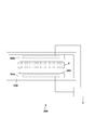
図1には、本発明の第1実施形態の冷却装置1の構成が示されている。冷却装置1による冷却対象は、特別な対象に限定されるものではないが、例えば、半導体製造装置、特に半導体製造装置の発熱部でありうる。半導体製造装置は、例えば、露光装置、インプリント装置、荷電粒子線描画装置等のパターン形成装置、あるいは、CVD装置、エッチング装置、スパッタリング装置等のプラズマ処理装置でありうる。パターン形成装置は、基板および/または原版等の部品を高速で移動させる駆動機構を有し、該駆動機構は、物品の駆動に伴って発熱し、発熱部となりうる。プラズマ処理装置では、プラズマによって電極等の部品が加熱され、該部品が発熱部となりうる。
冷却装置1は、発熱部等の冷却対象物80を冷却するように構成されうる。冷却装置1は、タンク10と、タンク10から液相の冷媒12を取り出して熱交換器26で冷却しタンク10に戻すように液相の冷媒12をポンプ22によって循環させる第1経路20と、第1経路20から分岐した第2経路30とを備えうる。
第1経路20からの第2経路30の分岐点P1は、ポンプ22と熱交換器26との間に配置されうる。第1経路20は、熱交換器26とタンク10との間に配置された第1絞り24を有しうる。第1絞り24は、液相の冷媒12の圧力を降下させうる。第1絞り24は、第1経路20からの第2経路30の分岐点P1と熱交換器26の間に配置されてもよい。
第1経路20では、冷媒12が液相の状態で循環されうる。よって、液相と気相とが混在する系におけるようなキャビテーションによってポンプがダメージを受けることを考慮する必要がない。そのため、第1実施形態によれば、第1経路20に気相の冷媒12を液相に変化させるための凝縮器を設ける必要がなく、簡易な構成の冷却装置1が実現されうる。ただし、第1経路20の設計においては、液相の冷媒12の移送におけるキャビテーションの発生が防止されるようにポンプ22の仕様等が決定されうる。例えば、最もキャビテーションが発生しやすいポンプ22の吸い込み部において、冷媒12の圧力が冷媒12の吸い込み部の温度における飽和蒸気圧とポンプ22固有のNPSH(Net Positive Suction Headの略。)との合算値より大きくなる様にポンプ22の選定並びに循環系路の流量と圧損を決定すればよい。
第2経路30は、例えば、加熱器32と、絞り(第2絞り)34と、気化器36とを含み、気化器36を通過した冷媒をタンク10に戻すように構成されうる。加熱器32は、第1経路20から供給される液相の冷媒12を所定の温度に加熱する。絞り32は、加熱器32によって所定の温度に加熱された冷媒12の圧力を所定の温度下における飽和蒸気圧近傍まで降下させ、冷媒12を沸騰しやすい状態にする。気化器36は、絞り34を通過した冷媒12の少なくとも一部を冷却対象物80からの熱によって沸騰気化させる。気化器36を通過した気液2相混合状態の冷媒12は、タンク10に戻され、第1経路20で冷却された液相の冷媒12との混合によって冷却され、気相から液相に変化しうる(即ち、凝縮しうる)。冷却装置1は、絞り34を通過した冷媒12の温度を検出する温度検出器42と、温度検出器42の出力に基づいて加熱器32を制御する温度制御器44とを更に備えうる。これにより、目標温度に設定された冷媒12が気化器36に供給されうる。
第1実施形態によれば、冷却装置1は、冷媒12の相変化が気化器36とタンク10の2箇所に限定され、更に、温度差が異なる冷媒12の混合によって液相の冷媒12を凝縮させる。よって、冷却装置1で回収された熱を系外に排出する手段は熱交換器26の一つでよい。これによって、簡易な構成の冷却装置1が実現されうる。
図2には、第2実施形態の冷却装置1の構成が示されている。第2実施形態の冷却装置1は、第1実施形態の冷却装置1の改良型であり、第2実施形態として言及しない事項は、第1実施形態に従いうる。第2実施形態の冷却装置1は、タンク10における気化した冷媒12の量を検出する検出部52と、検出部52の出力に基づいて熱交換器26(における熱交換)を制御する制御器54とを追加的に備えうる。タンク10における気化した冷媒12の量は、タンク10の中の圧力に依存する。したがって、検出部52は、タンク10の中の圧力を検出することによって、タンク10における気化した冷媒12の量を検出することができる。タンク10における気化した冷媒12の量(換言すると、タンク10の中の圧力)は、タンク10の中の液相の冷媒12の温度にも依存する。したがって、検出部52の出力に基づいて制御器54が熱交換器26(における熱交換)を制御することによって、第1経路20を循環する液相の冷媒12の温度を制御することができ、更には、気化した冷媒12の凝縮量を制御することができる。
冷媒12の凝縮量を制御するには、タンク10の内部で常に気相の冷媒12が存在しなければならない。これを実現するために、タンク10には、タンク10の温度下で凝縮しないガス72が封入されうる。ガス72は、冷媒12と反応しないガスである。
図3は、冷却装置1における冷媒12の相図である。図3には、飽和蒸気圧線と熱サイクルが例示され、飽和蒸気圧線より上側では冷媒12は液相であり、飽和蒸気圧線より下側では冷媒12が気相である。第1経路20では、液相の冷媒12はポンプ22によってタンク10から吸い出されて加圧されて状態S2となり、熱交換器26で冷却されて状態S5になり、更に絞り24で減圧されて状態S6となってタンク10に戻される。
第2経路30では、状態S2における冷媒12は、加熱器32によって加熱されて状態S3になり、その後、絞り34で減圧されて状態S4となり、気化器36を通してタンク10に戻される。ガス72は、タンク10に戻される冷媒12の蒸気圧と、タンク10の中の(温度が制御された)液相の冷媒12の蒸気圧との差に相当する分圧(「ガス分圧」)を与えるようにタンク10内に所定量封入されている。これにより、第2経路30を通してタンク10に戻った冷媒12は、状態S1の温度下における飽和蒸気圧分の気体として存在することができる。ここで、ガス72による分圧がないと、冷媒12は、状態S1において飽和蒸気圧線の上側の状態、即ち液相状態となってしまう。ガス72の分圧をポンプ22のNPSH以上にすることは、キャビテーションの発生を防ぐことと等価である。よって、ガス72の分圧は、ポンプ22のNPSH以上とされうる。
冷却対象物80が発熱すると、第2経路30の気化器36で冷媒12が気化して潜熱として熱を吸収しタンク10に戻され、タンク10内の圧力が上昇する。その上昇分が検出器52で検出され、常にタンク10の圧力が所定の圧力、即ち状態S4の温度における冷媒12の飽和蒸気圧になる様に、制御器54が第1経路20の冷媒12の温度を下げる方向に制御する。逆に、冷却対象物80の発熱がなくなると、第2経路30の気化器36で冷媒12が気化しなくなり、タンク10内の圧力が降下する。その上昇分が検出器52で検出され、常にタンク10の圧力が所定圧力、即ち状態S4の温度における冷媒12の飽和蒸気圧になる様に、制御器54が第1経路20の冷媒12の温度を上げる方向に制御する。
これにより、冷却対象物80の発熱状態に追従して、冷却対象物80を状態S4の一定温度で冷媒12の気化潜熱で熱を回収し熱交換器26で系外部へ排出することができる。ここで、第2経路の冷媒12が気液2相流となる気化器26とタンク10との間の管は、管径を大きくし、圧力損出を極力小さくし気化器26とタンク10の差圧を小さくすることが好ましい。これにより、冷却対象物80の発熱量変化による温度変動を抑えることができる。
図4には、第3実施形態の冷却装置1の構成が示されている。第3実施形態の冷却装置1は、第2実施形態の冷却装置1の改良型であり、第3実施形態として言及しない事項は、第1、第2実施形態に従いうる。第3実施形態の冷却装置1では、タンク10は、タンク10の中の水平断面積よりも大きい断面積を有する部材14を有する。部材14は、タンク10の中の液相の冷媒12および第2経路30から戻される冷媒12に接触するように配置されうる。部材14は、例えば、表面に凹凸を有する部材、メッシュ状の部材、複数の孔を有する部材、または、多孔質部材でありうる。第1経路20からタンク10に戻される液相の冷媒12は、部材14の上方から落下するようにタンク10に戻されうる。あるいは、第1経路20からタンク10に戻される液相の冷媒12をシャワー状またはミスト状にしてタンク10の上部から滴下または噴霧させてもよい。
これにより、第1経路20において熱交換器26によって冷却された低温の液相の冷媒12と、第2経路30から戻ってくる高温の冷媒12との接触面積が増加し、第2経路30から戻ってくる高温の冷媒12を凝縮させる効率が改善しうる。
図5には、第4実施形態の冷却装置1の構成が示されている。第4実施形態の冷却装置1は、第1乃至第3実施形態の冷却装置1の改良型であり、第4実施形態として言及しない事項は、第1乃至第3実施形態に従いうる。
第4実施形態の冷却装置1は、第1経路20に設けられた熱交換器26が排出した熱を第2経路30に設けられた加熱器32に移動させるヒートポンプ92を更に備えうる。加熱器32は、ヒートポンプ92から提供される熱を利用して、第1経路20から分岐して供給される第2経路30の液相の冷媒12を加熱するように構成されうる。ヒートポンプ92は、例えば、温度検出器42の出力に基づいて制御されうる。あるいは、ヒートポンプ92は、温度検出器42の出力および検出部52の出力に基づいて制御されうる。
第4実施形態によれば、第1経路20の熱交換器26が排出した熱を利用して第2経路30の加熱器32が冷媒12を加熱することによってエネルギー消費を低減することができる。
図6には、第5実施形態の冷却装置1の構成が示されている。第5実施形態の冷却装置1は、第1乃至第4実施形態の冷却装置1の改良型であり、第5実施形態として言及しない事項は、第1乃至第4実施形態に従いうる。第5実施形態の冷却装置1は、加熱器32によって加熱された冷媒12と第2冷却対象物82との間で熱交換を行う第2熱交換器96を更に備える。第2熱交換器96を通過した冷媒12は、タンク10に戻されうる。第2熱交換器96とタンク10との間の経路には、絞り98が配置されうる。加熱器32と第2冷却対象物82との間には、絞りが配置されないことが好ましい。これは、冷媒12の圧力が高い状態で第2冷却対象物82へ供給することにより冷媒12の相変化をさせずに第2冷却対象物82の熱回収を行うことができるためである。これにより、冷媒12の相変化時に発生する微振動が第2冷却対象物82に伝達しなくなる。
第5実施形態の冷却装置1は、例えば、発熱量が相対的に大きく、振動に対する許容度が相対的に高い冷却対象物(第1冷却対象物)80と、発熱量が相対的に小さく、振動に対する許容度が相対的に小さい第2冷却対象物82とを冷却するために有用である。そのような第1冷却対象物80および第2冷却対象物82を有する装置としては、例えば、粗動機構おおよび微動機構を備える位置決め装置(ステージ装置)を挙げることができる。ここで、粗動機構は、微動機構を粗駆動し、微動機構は、位置決め対象物(例えば、基板、または、基板ステージ)を微駆動するように構成されうる。粗駆動機構のアクチュエータは、第1冷却対象物80でありうる。微動機構のアクチュエータは、第2冷却対象物82でありうる。
以下、図7、図8および図9を参照しながら上記の冷却装置1が適用された半導体製造装置について例示的に説明する。図7には、半導体製造装置、より詳しくはパターン形成装置の一例としての露光装置100の構成が模式的に示されている。露光装置100は、原版101のパターンを、感光材層を有する基板102の該感光材層に対して投影光学系140によって転写するように構成されうる。露光装置100は、原版101を照明する照明光学系150と、投影光学系140と、基板位置決め機構SPMとを備えうる。また、露光装置100は、原版101を位置決めする原版位置決め機構(不図示)を備えうる。基板位置決め機構SPMは、基板102を保持する基板チャックを有する基板ステージ110と、基板ステージ110を駆動する駆動機構120と、駆動機構120を支持するベース部材130とを含みうる。駆動機構120は、基板ステージ110とともに移動する可動子122と、ベース部材130に固定された固定子124とを含むアクチュエータを有しうる。固定子124は、冷却対象物80としてのコイル列を含みうる。冷却装置1は、冷却対象物80としてのコイル列を冷却するように構成されうる。
図8には、半導体製造装置、より詳しくはパターン形成装置の一例としてのインプリント装置200の構成が模式的に示されている。インプリント装置200は、基板102の上のインプリント材に原版101のパターンを転写するように構成されうる。インプリント装置200は、原版101を駆動する原版駆動機構160と、基板102を駆動する基板駆動機構SPMと、基板102の上に配置されたインプリント材を硬化させる硬化部170とを備えうる。
原版駆動機構160および基板駆動機構SPMの少なくとも一方によって基板102のショット領域と原版101のパターン領域とのアライメントを行うことができる。原版駆動機構160および基板駆動機構SPMの少なくとも一方によって、基板102の上に配置されたインプリント材と原版101のパターン領域との接触、および、インプリント材とパターン領域との分離を行うことができる。基板102の上に配置されたインプリント材と原版101のパターン領域とを接触させた状態で、硬化部170によってインプリント材が硬化される。その後、硬化したインプリント材と原版101のパターン領域とが分離される。これにより、基板102の上にインプリント材の硬化物からなるパターンが形成される。つまり、基板102の上のインプリント材には、原版101のパターン領域が転写される。
基板位置決め機構SPMは、基板102を保持する基板チャックを有する基板ステージ110と、基板ステージ110を駆動する駆動機構120と、駆動機構120を支持するベース部材130とを含みうる。駆動機構120は、基板ステージ110とともに移動する可動子122と、ベース部材130に固定された固定子124とを含むアクチュエータを有しうる。固定子124は、冷却対象物80としてのコイル列を含みうる。冷却装置1は、冷却対象物80としてのコイル列を冷却するように構成されうる。
図9には、半導体製造装置の一例としてのプラズマ処理装置300の構成が模式的に示されている。プラズマ処理装置300は、例えば、CVD装置、エッチング装置またはスパッタリング装置でありうる。プラズマ処理装置300は、チャンバ330と、チャンバ330の中に配置された1または複数の冷却対象物80a、80bとしての電極構造を備えうる。図9の例では、基板302は、冷却対象物80aによって支持されうる。チャンバ330の中には、プラズマを発生させるためのガスが供給されうる。プラズマ処理装置300がCVD装置として構成される場合、チャンバ330の中には、成膜用のガスが供給されうる。プラズマ処理装置300がエッチング装置として構成される場合、チャンバ330の中には、エッチング用のガスが供給されうる。プラズマ処理装置300がスパッタリング装置として構成される場合、チャンバ330の中には、プラズマを発生させるためのガスが供給され、また、冷却対象物80bとしての電極構造には、ターゲットが取り付けられうる。冷却装置1は、冷却対象物80a、80bを冷却するように構成されうる。
本発明の1つの側面としての半導体製造方法は、上記の露光装置100、インプリント装置200およびプラズマ処理装置300に代表される半導体製造装置によって基板を処理する工程と、該工程によって処理された基板を加工する工程と、を含みうる。半導体製造装置によって基板を処理する工程は、例えば、基板にパターンを形成する工程、基板に膜を形成する工程、または、基板またはその上に形成された膜をエッチングする工程でありうる。基板を加工する工程は、例えば、基板にパターンを形成する工程、基板に膜を形成する工程、または、基板またはその上に形成された膜をエッチングする工程でありうる。あるいは、基板を加工する工程は、基板を分割(ダイシング)する工程、または、基板を封止する工程でありうる。
本発明は上記実施の形態に制限されるものではなく、本発明の精神及び範囲から離脱することなく、様々な変更及び変形が可能である。従って、本発明の範囲を公にするために、以下の請求項を添付する。
本願は、2017年12月26日提出の日本国特許出願特願2017-250107号を基礎として優先権を主張するものであり、その記載内容の全てを、ここに援用する。
Claims (21)
- タンクと、
前記タンクから液相の冷媒を取り出して冷却し前記タンクに戻すように液相の冷媒をポンプによって循環させる第1経路と、
前記第1経路から分岐した第2経路と、を備え、
前記第2経路は、前記第1経路から供給される液相の冷媒を加熱する加熱器と、前記加熱器によって加熱された冷媒の圧力を降下させる絞りと、前記絞りを通過した冷媒の少なくとも一部を冷却対象物からの熱によって気化させる気化器とを含み、前記気化器を通過した冷媒を前記タンクに戻す、
ことを特徴とする冷却装置。 - 前記絞りを通過した冷媒の温度を検出する温度検出器と、
前記温度検出器の出力に基づいて前記加熱器を制御する温度制御器と、
を更に備えることを特徴とする請求項1に記載の冷却装置。 - 前記第1経路は、熱交換器を含み、前記タンクから前記ポンプによって吸い出された冷媒が前記熱交換器を通して前記タンクに戻される、
ことを特徴とする請求項2に記載の冷却装置。 - 前記第1経路からの前記第2経路の分岐点は、前記ポンプと前記熱交換器との間に配置されている、
ことを特徴とする請求項3に記載の冷却装置。 - 前記第1経路は、前記第2経路の前記分岐点と前記タンクとの間に配置された第1絞りを更に備える、
ことを特徴とする請求項4に記載の冷却装置。 - 前記タンクにおける気化した冷媒の量を検出する検出部と、
前記検出部の出力に基づいて前記熱交換器を制御する制御器と、
を更に備えることを特徴とする請求項3乃至5のいずれか1項に記載の冷却装置。 - 前記タンクには、前記タンクの中で気化しないガスが封入されている、
ことを特徴とする請求項6に記載の冷却装置。 - 前記ガスは、前記第2経路から前記タンクに戻される冷媒の蒸気圧と前記タンクの中の冷媒の蒸気圧との差に相当する分圧を発生する、
ことを特徴とする請求項7に記載の冷却装置。 - 前記ガスの分圧は、前記ポンプのNPSH(Net Positive Suction Head)以上である、
ことを特徴とする請求項7に記載の冷却装置。 - 前記熱交換器が排出した熱を前記加熱器に移動させるヒートポンプを更に備え、
前記加熱器は、前記ヒートポンプから提供される熱を利用して、前記第1経路から供給される液相の冷媒を加熱するように構成されている、
ことを特徴とする請求項3乃至9のいずれか1項に記載の冷却装置。 - 前記ヒートポンプは、前記温度検出器の出力に基づいて制御される、
ことを特徴とする請求項10に記載の冷却装置。 - 前記熱交換器が排出した熱を前記加熱器に移動させるヒートポンプを更に備え、
前記加熱器は、前記ヒートポンプから提供される熱を利用して、前記第1経路から供給される液相の冷媒を加熱するように構成され、
前記ヒートポンプは、前記温度検出器の出力および前記検出部の出力に基づいて制御される、
ことを特徴とする請求項6乃至9のいずれか1項に記載の冷却装置。 - 前記タンクは、前記タンクの中の水平断面積よりも大きい断面積を有する部材を有し、
前記部材は、前記タンクの中の液相の冷媒および前記第2経路から戻される冷媒に接触するように配置されている、
ことを特徴とする請求項1乃至12のいずれか1項に記載の冷却装置。 - 前記第1経路から前記タンクに戻される冷媒は、前記部材の上方から落下するように前記タンクに戻される、
ことを特徴とする請求項13に記載の冷却装置。 - 前記第1経路から前記タンクに戻される冷媒は、前記タンクの上方からシャワー状またはミスト状にして滴下または噴霧される、
ことを特徴とする請求項1乃至13のいずれか1項に記載の冷却装置。 - 前記加熱器によって加熱された冷媒と第2冷却対象物との間で熱交換を行う第2熱交換器を更に備える、
ことを特徴とする請求項1乃至15のいずれか1項に記載の冷却装置。 - 前記第2熱交換器を通過した冷媒が前記タンクに戻される、
ことを特徴とする請求項16に記載の冷却装置。 - 前記第2熱交換器と前記タンクとの間の経路に配置された絞りを更に備える、
ことを特徴とする請求項17に記載の冷却装置。 - 発熱部を有する半導体製造装置であって、
請求項1乃至18のいずれか1項に記載の冷却装置を備え、
前記冷却装置は、前記冷却対象物としての前記発熱部を冷却するように構成されている、
ことを特徴とする半導体製造装置。 - パターンを形成するパターン形成装置として構成されている、
ことを特徴とする請求項19に記載の半導体製造装置。 - 請求項19又は20に記載の半導体製造装置によって基板を処理する工程と、
前記工程で処理された基板を加工する工程と、
を含むことを特徴とする半導体製造方法。
Priority Applications (4)
| Application Number | Priority Date | Filing Date | Title |
|---|---|---|---|
| EP18897285.5A EP3712703B1 (en) | 2017-12-26 | 2018-11-29 | Cooling device, semiconductor manufacturing device, and semiconductor manufacturing method |
| KR1020207020305A KR102427104B1 (ko) | 2017-12-26 | 2018-11-29 | 냉각장치, 반도체 제조장치 및 반도체 제조방법 |
| CN201880083832.0A CN111527452B (zh) | 2017-12-26 | 2018-11-29 | 冷却设备、半导体制造装置和半导体制造方法 |
| US16/909,355 US20200318230A1 (en) | 2017-12-26 | 2020-06-23 | Cooling device, semiconductor manufacturing apparatus, and semiconductor manufacturing method |
Applications Claiming Priority (2)
| Application Number | Priority Date | Filing Date | Title |
|---|---|---|---|
| JP2017-250107 | 2017-12-26 | ||
| JP2017250107A JP6971836B2 (ja) | 2017-12-26 | 2017-12-26 | 冷却装置、半導体製造装置および半導体製造方法 |
Related Child Applications (1)
| Application Number | Title | Priority Date | Filing Date |
|---|---|---|---|
| US16/909,355 Continuation US20200318230A1 (en) | 2017-12-26 | 2020-06-23 | Cooling device, semiconductor manufacturing apparatus, and semiconductor manufacturing method |
Publications (1)
| Publication Number | Publication Date |
|---|---|
| WO2019130970A1 true WO2019130970A1 (ja) | 2019-07-04 |
Family
ID=67067243
Family Applications (1)
| Application Number | Title | Priority Date | Filing Date |
|---|---|---|---|
| PCT/JP2018/043987 Ceased WO2019130970A1 (ja) | 2017-12-26 | 2018-11-29 | 冷却装置、半導体製造装置および半導体製造方法 |
Country Status (6)
| Country | Link |
|---|---|
| US (1) | US20200318230A1 (ja) |
| EP (1) | EP3712703B1 (ja) |
| JP (1) | JP6971836B2 (ja) |
| KR (1) | KR102427104B1 (ja) |
| CN (1) | CN111527452B (ja) |
| WO (1) | WO2019130970A1 (ja) |
Cited By (3)
| Publication number | Priority date | Publication date | Assignee | Title |
|---|---|---|---|---|
| CN111707042A (zh) * | 2020-06-30 | 2020-09-25 | 长沙新材料产业研究院有限公司 | 一种mpcvd金刚石合成设备供水保护系统及方法 |
| WO2025110117A1 (ja) * | 2023-11-24 | 2025-05-30 | キヤノン株式会社 | 冷却装置、基板処理装置、及び物品の製造方法 |
| TWI915282B (zh) | 2024-08-27 | 2026-02-11 | 日商斯庫林集團股份有限公司 | 基板處理系統 |
Families Citing this family (5)
| Publication number | Priority date | Publication date | Assignee | Title |
|---|---|---|---|---|
| CN112034689B (zh) * | 2020-09-21 | 2021-10-08 | 华中科技大学 | 一种浸没式光刻机浸液温控装置 |
| JP7555876B2 (ja) * | 2021-05-24 | 2024-09-25 | 株式会社荏原製作所 | サブファブエリア設置装置 |
| JP7644666B2 (ja) * | 2021-06-23 | 2025-03-12 | キヤノン株式会社 | 温度調整装置、処理装置および物品製造方法 |
| CN113587527B (zh) * | 2021-08-06 | 2022-09-02 | 中国电子科技集团公司第三十八研究所 | 一种双流体回路雷达阵面冷却系统 |
| JP7784620B2 (ja) | 2022-01-14 | 2025-12-12 | 株式会社東京精密 | チラーシステム |
Citations (5)
| Publication number | Priority date | Publication date | Assignee | Title |
|---|---|---|---|---|
| JPS5313384B2 (ja) | 1974-06-12 | 1978-05-10 | ||
| JP2004349551A (ja) * | 2003-05-23 | 2004-12-09 | Denso Corp | 沸騰冷却システム |
| JP2008304093A (ja) * | 2007-06-06 | 2008-12-18 | Hitachi Ltd | 気化冷却システム |
| JP2009543320A (ja) * | 2006-07-01 | 2009-12-03 | 株式会社ニコン | 駆動部用の相変化循環システムを有する露光装置 |
| JP5313384B2 (ja) * | 2011-04-20 | 2013-10-09 | エーエスエムエル ネザーランズ ビー.ブイ. | リソグラフィ装置の一部を熱調節する熱調節システム及び熱調節方法 |
Family Cites Families (14)
| Publication number | Priority date | Publication date | Assignee | Title |
|---|---|---|---|---|
| KR970016424A (ko) * | 1995-09-28 | 1997-04-28 | 배순훈 | 공기조화기의 냉매 여과장치 |
| KR19990008915A (ko) * | 1997-07-04 | 1999-02-05 | 구자홍 | 암모니아 흡수식 시스템의 에널라이저 구조 |
| US7789962B2 (en) * | 2005-03-31 | 2010-09-07 | Tokyo Electron Limited | Device and method for controlling temperature of a mounting table, a program therefor, and a processing apparatus including same |
| US7908874B2 (en) * | 2006-05-02 | 2011-03-22 | Raytheon Company | Method and apparatus for cooling electronics with a coolant at a subambient pressure |
| JP4648877B2 (ja) * | 2006-07-04 | 2011-03-09 | 住友重機械工業株式会社 | 温度制御装置における液排出方法および液排出装置 |
| JP5185790B2 (ja) * | 2008-11-27 | 2013-04-17 | 株式会社日立ハイテクノロジーズ | プラズマ処理装置 |
| JP5947023B2 (ja) * | 2011-11-14 | 2016-07-06 | 東京エレクトロン株式会社 | 温度制御装置、プラズマ処理装置、処理装置及び温度制御方法 |
| US10553463B2 (en) * | 2011-11-15 | 2020-02-04 | Tokyo Electron Limited | Temperature control system, semiconductor manufacturing device, and temperature control method |
| JP5914037B2 (ja) * | 2012-02-23 | 2016-05-11 | 東京エレクトロン株式会社 | 冷却システム、冷却システムを備える基板処理装置及び冷却方法 |
| US20130240144A1 (en) * | 2012-03-13 | 2013-09-19 | Applied Materials, Inc. | Fast response fluid temperature control system |
| FR3020090B1 (fr) * | 2014-04-16 | 2019-04-12 | IFP Energies Nouvelles | Dispositif de controle d'un circuit ferme fonctionnant selon un cycle de rankine et procede utilisant un tel dispositif |
| JP6570390B2 (ja) * | 2015-09-24 | 2019-09-04 | 東京エレクトロン株式会社 | 温度調整装置及び基板処理装置 |
| KR101720752B1 (ko) * | 2016-04-22 | 2017-04-03 | 한국기계연구원 | 초전도 한류기 복귀 시스템 |
| US10330361B2 (en) * | 2017-01-26 | 2019-06-25 | Hamilton Sundstrand Corporation | Passive liquid collecting device |
-
2017
- 2017-12-26 JP JP2017250107A patent/JP6971836B2/ja active Active
-
2018
- 2018-11-29 CN CN201880083832.0A patent/CN111527452B/zh active Active
- 2018-11-29 KR KR1020207020305A patent/KR102427104B1/ko active Active
- 2018-11-29 EP EP18897285.5A patent/EP3712703B1/en active Active
- 2018-11-29 WO PCT/JP2018/043987 patent/WO2019130970A1/ja not_active Ceased
-
2020
- 2020-06-23 US US16/909,355 patent/US20200318230A1/en active Pending
Patent Citations (5)
| Publication number | Priority date | Publication date | Assignee | Title |
|---|---|---|---|---|
| JPS5313384B2 (ja) | 1974-06-12 | 1978-05-10 | ||
| JP2004349551A (ja) * | 2003-05-23 | 2004-12-09 | Denso Corp | 沸騰冷却システム |
| JP2009543320A (ja) * | 2006-07-01 | 2009-12-03 | 株式会社ニコン | 駆動部用の相変化循環システムを有する露光装置 |
| JP2008304093A (ja) * | 2007-06-06 | 2008-12-18 | Hitachi Ltd | 気化冷却システム |
| JP5313384B2 (ja) * | 2011-04-20 | 2013-10-09 | エーエスエムエル ネザーランズ ビー.ブイ. | リソグラフィ装置の一部を熱調節する熱調節システム及び熱調節方法 |
Non-Patent Citations (1)
| Title |
|---|
| See also references of EP3712703A4 |
Cited By (3)
| Publication number | Priority date | Publication date | Assignee | Title |
|---|---|---|---|---|
| CN111707042A (zh) * | 2020-06-30 | 2020-09-25 | 长沙新材料产业研究院有限公司 | 一种mpcvd金刚石合成设备供水保护系统及方法 |
| WO2025110117A1 (ja) * | 2023-11-24 | 2025-05-30 | キヤノン株式会社 | 冷却装置、基板処理装置、及び物品の製造方法 |
| TWI915282B (zh) | 2024-08-27 | 2026-02-11 | 日商斯庫林集團股份有限公司 | 基板處理系統 |
Also Published As
| Publication number | Publication date |
|---|---|
| CN111527452B (zh) | 2022-08-12 |
| CN111527452A (zh) | 2020-08-11 |
| EP3712703A1 (en) | 2020-09-23 |
| EP3712703A4 (en) | 2021-07-28 |
| US20200318230A1 (en) | 2020-10-08 |
| EP3712703B1 (en) | 2023-07-26 |
| KR102427104B1 (ko) | 2022-07-29 |
| JP2019117231A (ja) | 2019-07-18 |
| JP6971836B2 (ja) | 2021-11-24 |
| KR20200098632A (ko) | 2020-08-20 |
Similar Documents
| Publication | Publication Date | Title |
|---|---|---|
| CN113847759B (zh) | 冷却装置、半导体制造装置和半导体制造方法 | |
| WO2019130970A1 (ja) | 冷却装置、半導体製造装置および半導体製造方法 | |
| US8426764B2 (en) | Plasma processing apparatus and plasma processing method | |
| US6990816B1 (en) | Hybrid capillary cooling apparatus | |
| CN102749809B (zh) | 用于热调节光刻设备的部份的热调节系统和热调节方法 | |
| JP5947023B2 (ja) | 温度制御装置、プラズマ処理装置、処理装置及び温度制御方法 | |
| US20250012494A1 (en) | Cooling device, semiconductor manufacturing apparatus and semiconductor manufacturing method | |
| US20230137699A1 (en) | Method for the stabilisation and/or open-loop and/or closed-loop control of a working temperature, heat exchanger unit, device for transporting energy, refrigerating machine and heat pump | |
| JPH01285607A (ja) | ハイブリッドバイナリー発電システム | |
| JPH0143574B2 (ja) | ||
| JP7622541B2 (ja) | 冷却システム | |
| JP2021061293A (ja) | 熱サイクル装置 | |
| JP2025085399A (ja) | 冷却装置、基板処理装置、及び物品の製造方法 | |
| KR102233280B1 (ko) | 진동형 히트파이프를 적용한 극저온 루프 히트파이프 | |
| JP6801665B2 (ja) | 相変化冷却装置およびその制御方法 | |
| JP2003222427A (ja) | 温調システム | |
| JP2015192933A (ja) | 蒸留設備 | |
| JPS63264268A (ja) | 気相式はんだ付け装置におけるワ−ク急冷装置 | |
| JP2020161655A (ja) | 冷却システム | |
| JP2010091146A (ja) | 冷却システム |
Legal Events
| Date | Code | Title | Description |
|---|---|---|---|
| 121 | Ep: the epo has been informed by wipo that ep was designated in this application |
Ref document number: 18897285 Country of ref document: EP Kind code of ref document: A1 |
|
| ENP | Entry into the national phase |
Ref document number: 2018897285 Country of ref document: EP Effective date: 20200618 |
|
| NENP | Non-entry into the national phase |
Ref country code: DE |
|
| ENP | Entry into the national phase |
Ref document number: 20207020305 Country of ref document: KR Kind code of ref document: A |