WO2019131134A1 - 受光素子および電子機器 - Google Patents
受光素子および電子機器 Download PDFInfo
- Publication number
- WO2019131134A1 WO2019131134A1 PCT/JP2018/045704 JP2018045704W WO2019131134A1 WO 2019131134 A1 WO2019131134 A1 WO 2019131134A1 JP 2018045704 W JP2018045704 W JP 2018045704W WO 2019131134 A1 WO2019131134 A1 WO 2019131134A1
- Authority
- WO
- WIPO (PCT)
- Prior art keywords
- layer
- photoelectric conversion
- receiving element
- light receiving
- electrode
- Prior art date
- Legal status (The legal status is an assumption and is not a legal conclusion. Google has not performed a legal analysis and makes no representation as to the accuracy of the status listed.)
- Ceased
Links
Images












Classifications
-
- H—ELECTRICITY
- H10—SEMICONDUCTOR DEVICES; ELECTRIC SOLID-STATE DEVICES NOT OTHERWISE PROVIDED FOR
- H10F—INORGANIC SEMICONDUCTOR DEVICES SENSITIVE TO INFRARED RADIATION, LIGHT, ELECTROMAGNETIC RADIATION OF SHORTER WAVELENGTH OR CORPUSCULAR RADIATION
- H10F39/00—Integrated devices, or assemblies of multiple devices, comprising at least one element covered by group H10F30/00, e.g. radiation detectors comprising photodiode arrays
- H10F39/10—Integrated devices
- H10F39/12—Image sensors
- H10F39/191—Photoconductor image sensors
- H10F39/193—Infrared image sensors
-
- H—ELECTRICITY
- H10—SEMICONDUCTOR DEVICES; ELECTRIC SOLID-STATE DEVICES NOT OTHERWISE PROVIDED FOR
- H10F—INORGANIC SEMICONDUCTOR DEVICES SENSITIVE TO INFRARED RADIATION, LIGHT, ELECTROMAGNETIC RADIATION OF SHORTER WAVELENGTH OR CORPUSCULAR RADIATION
- H10F39/00—Integrated devices, or assemblies of multiple devices, comprising at least one element covered by group H10F30/00, e.g. radiation detectors comprising photodiode arrays
- H10F39/80—Constructional details of image sensors
- H10F39/805—Coatings
- H10F39/8057—Optical shielding
-
- H—ELECTRICITY
- H04—ELECTRIC COMMUNICATION TECHNIQUE
- H04N—PICTORIAL COMMUNICATION, e.g. TELEVISION
- H04N25/00—Circuitry of solid-state image sensors [SSIS]; Control thereof
- H04N25/70—SSIS architectures; Circuits associated therewith
-
- H—ELECTRICITY
- H04—ELECTRIC COMMUNICATION TECHNIQUE
- H04N—PICTORIAL COMMUNICATION, e.g. TELEVISION
- H04N5/00—Details of television systems
- H04N5/30—Transforming light or analogous information into electric information
- H04N5/33—Transforming infrared radiation
-
- H—ELECTRICITY
- H10—SEMICONDUCTOR DEVICES; ELECTRIC SOLID-STATE DEVICES NOT OTHERWISE PROVIDED FOR
- H10F—INORGANIC SEMICONDUCTOR DEVICES SENSITIVE TO INFRARED RADIATION, LIGHT, ELECTROMAGNETIC RADIATION OF SHORTER WAVELENGTH OR CORPUSCULAR RADIATION
- H10F30/00—Individual radiation-sensitive semiconductor devices in which radiation controls the flow of current through the devices, e.g. photodetectors
- H10F30/20—Individual radiation-sensitive semiconductor devices in which radiation controls the flow of current through the devices, e.g. photodetectors the devices having potential barriers, e.g. phototransistors
-
- H—ELECTRICITY
- H10—SEMICONDUCTOR DEVICES; ELECTRIC SOLID-STATE DEVICES NOT OTHERWISE PROVIDED FOR
- H10F—INORGANIC SEMICONDUCTOR DEVICES SENSITIVE TO INFRARED RADIATION, LIGHT, ELECTROMAGNETIC RADIATION OF SHORTER WAVELENGTH OR CORPUSCULAR RADIATION
- H10F39/00—Integrated devices, or assemblies of multiple devices, comprising at least one element covered by group H10F30/00, e.g. radiation detectors comprising photodiode arrays
- H10F39/011—Manufacture or treatment of image sensors covered by group H10F39/12
- H10F39/021—Manufacture or treatment of image sensors covered by group H10F39/12 of image sensors having active layers comprising only Group III-V materials, e.g. GaAs, AlGaAs or InP
-
- H—ELECTRICITY
- H10—SEMICONDUCTOR DEVICES; ELECTRIC SOLID-STATE DEVICES NOT OTHERWISE PROVIDED FOR
- H10F—INORGANIC SEMICONDUCTOR DEVICES SENSITIVE TO INFRARED RADIATION, LIGHT, ELECTROMAGNETIC RADIATION OF SHORTER WAVELENGTH OR CORPUSCULAR RADIATION
- H10F39/00—Integrated devices, or assemblies of multiple devices, comprising at least one element covered by group H10F30/00, e.g. radiation detectors comprising photodiode arrays
- H10F39/011—Manufacture or treatment of image sensors covered by group H10F39/12
- H10F39/024—Manufacture or treatment of image sensors covered by group H10F39/12 of coatings or optical elements
-
- H—ELECTRICITY
- H10—SEMICONDUCTOR DEVICES; ELECTRIC SOLID-STATE DEVICES NOT OTHERWISE PROVIDED FOR
- H10F—INORGANIC SEMICONDUCTOR DEVICES SENSITIVE TO INFRARED RADIATION, LIGHT, ELECTROMAGNETIC RADIATION OF SHORTER WAVELENGTH OR CORPUSCULAR RADIATION
- H10F39/00—Integrated devices, or assemblies of multiple devices, comprising at least one element covered by group H10F30/00, e.g. radiation detectors comprising photodiode arrays
- H10F39/10—Integrated devices
- H10F39/12—Image sensors
-
- H—ELECTRICITY
- H10—SEMICONDUCTOR DEVICES; ELECTRIC SOLID-STATE DEVICES NOT OTHERWISE PROVIDED FOR
- H10F—INORGANIC SEMICONDUCTOR DEVICES SENSITIVE TO INFRARED RADIATION, LIGHT, ELECTROMAGNETIC RADIATION OF SHORTER WAVELENGTH OR CORPUSCULAR RADIATION
- H10F39/00—Integrated devices, or assemblies of multiple devices, comprising at least one element covered by group H10F30/00, e.g. radiation detectors comprising photodiode arrays
- H10F39/80—Constructional details of image sensors
- H10F39/802—Geometry or disposition of elements in pixels, e.g. address-lines or gate electrodes
- H10F39/8023—Disposition of the elements in pixels, e.g. smaller elements in the centre of the imager compared to larger elements at the periphery
-
- H—ELECTRICITY
- H10—SEMICONDUCTOR DEVICES; ELECTRIC SOLID-STATE DEVICES NOT OTHERWISE PROVIDED FOR
- H10F—INORGANIC SEMICONDUCTOR DEVICES SENSITIVE TO INFRARED RADIATION, LIGHT, ELECTROMAGNETIC RADIATION OF SHORTER WAVELENGTH OR CORPUSCULAR RADIATION
- H10F39/00—Integrated devices, or assemblies of multiple devices, comprising at least one element covered by group H10F30/00, e.g. radiation detectors comprising photodiode arrays
- H10F39/80—Constructional details of image sensors
- H10F39/811—Interconnections
-
- H—ELECTRICITY
- H10—SEMICONDUCTOR DEVICES; ELECTRIC SOLID-STATE DEVICES NOT OTHERWISE PROVIDED FOR
- H10F—INORGANIC SEMICONDUCTOR DEVICES SENSITIVE TO INFRARED RADIATION, LIGHT, ELECTROMAGNETIC RADIATION OF SHORTER WAVELENGTH OR CORPUSCULAR RADIATION
- H10F39/00—Integrated devices, or assemblies of multiple devices, comprising at least one element covered by group H10F30/00, e.g. radiation detectors comprising photodiode arrays
- H10F39/011—Manufacture or treatment of image sensors covered by group H10F39/12
- H10F39/016—Manufacture or treatment of image sensors covered by group H10F39/12 of thin-film-based image sensors
-
- H—ELECTRICITY
- H10—SEMICONDUCTOR DEVICES; ELECTRIC SOLID-STATE DEVICES NOT OTHERWISE PROVIDED FOR
- H10F—INORGANIC SEMICONDUCTOR DEVICES SENSITIVE TO INFRARED RADIATION, LIGHT, ELECTROMAGNETIC RADIATION OF SHORTER WAVELENGTH OR CORPUSCULAR RADIATION
- H10F39/00—Integrated devices, or assemblies of multiple devices, comprising at least one element covered by group H10F30/00, e.g. radiation detectors comprising photodiode arrays
- H10F39/10—Integrated devices
- H10F39/12—Image sensors
- H10F39/191—Photoconductor image sensors
Definitions
- the present disclosure relates to, for example, a light receiving element used for an infrared sensor and the like, and an electronic apparatus provided with the same.
- a semiconductor element in which a photoelectric conversion layer is formed using a compound semiconductor has been developed as an image sensor (infrared sensor) having sensitivity in the infrared region.
- image sensor infrared sensor
- the image sensor using this semiconductor element similarly to the light receiving element using Si, when the light shielding film is not disposed between the pixels, light leaks from the adjacent pixel region and color mixing occurs.
- Patent Document 1 discloses a photoelectric conversion device in which a transparent electrode layer is provided on the top of a photoelectric conversion layer using a compound semiconductor, and a light shielding film is disposed on the transparent electrode layer.
- the first light receiving element is provided as a common layer for a plurality of pixels and a plurality of pixels, and includes a photoelectric conversion unit including a compound semiconductor material and a plurality of light incident surface sides of the photoelectric conversion unit. And a first electrode layer having a light shielding property.
- a first electronic device of an embodiment of the present disclosure includes the first light receiving element of the embodiment of the present disclosure.
- a second light receiving element includes a plurality of pixels, a compound semiconductor material, and is provided as a common layer for the plurality of pixels, and the first contact layer and the second contact layer are interposed between the photoelectric conversion layers.
- a photoelectric conversion portion having a stacked structure in which the contact layers are stacked, an insulating layer provided on the photoelectric conversion portion, and a transparent electrode layer provided on the insulating layer.
- the second electronic device includes the second light receiving element according to the embodiment of the present disclosure.
- a first electrode layer having a light shielding property is provided between a plurality of pixels on the light incident surface side of the photoelectric conversion unit. I made it. Thereby, formation of the transparent electrode on a photoelectric conversion part becomes unnecessary.
- a photoelectric conversion layer has a laminated structure in which a first contact layer and a second contact layer are laminated between the photoelectric conversion layers. An insulating layer and a transparent electrode layer were laminated in this order on the conversion portion. Thus, the thickness of the first contact layer can be reduced.
- the first electrode layer having a light shielding property is provided between the plurality of pixels on the light incident surface side of the photoelectric conversion unit. Since the provision is made, the formation of the transparent electrode on the photoelectric conversion portion is unnecessary.
- the transparent electrode is formed on the photoelectric conversion unit via the insulating layer, so that the photoelectric conversion unit is formed. It is possible to reduce the thickness of the first contact layer provided on the light incident surface side of the light emitting diode. Therefore, the first light receiving element of the embodiment of the present disclosure and the first electronic device of the embodiment, and the second light receiving element of the embodiment of the present disclosure and the second electronic device of the embodiment have sensitivity It is possible to improve the
- FIG. 3A It is a cross-sectional schematic diagram showing the process of following FIG. 3B.
- FIG. 4A It is a cross-sectional schematic diagram showing the process of following FIG. 4B.
- FIG. 5A It is a cross-sectional schematic diagram showing the process of following FIG. 5A. It is a cross-sectional schematic diagram showing the process of following FIG. 5B. It is a cross-sectional schematic diagram showing the process of following FIG. 6A. It is a cross-sectional schematic diagram showing the process of following FIG. 6B. It is a cross-sectional schematic diagram showing the process of following FIG. 7A. It is a cross-sectional schematic diagram showing the process of following FIG. 7B. It is a cross-sectional schematic diagram showing the process of following FIG. 7C. It is a cross-sectional schematic diagram showing the process of following FIG. 8A. It is a cross-sectional schematic diagram showing the process of following FIG. 8B.
- FIG. 6 is a schematic cross-sectional view showing a schematic configuration of a light receiving element according to a first modification.
- FIG. 10 is a schematic cross-sectional view showing a schematic configuration of a light receiving element according to a second modification. It is a cross-sectional schematic diagram showing schematic structure of the light receiving element which concerns on 2nd Embodiment of this indication. It is a plane schematic diagram showing the whole structure of the light receiving element shown in FIG. It is a cross-sectional schematic diagram of the light receiving element in the II line shown to FIG. 12A. It is a cross-sectional schematic diagram of the light receiving element in the II-II line shown to FIG. 12A.
- FIG. 10 is a schematic cross-sectional view showing a schematic configuration of a light receiving element according to a third modification.
- FIG. 10 is a schematic cross-sectional view showing a schematic configuration of a light receiving element according to a fourth modification.
- FIG. 18 is a schematic cross-sectional view showing a schematic configuration of a light receiving element according to a fifth modification.
- FIG. 18 is a schematic cross-sectional view showing a schematic configuration of a light receiving element according to a sixth modification.
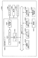
- It is a block diagram showing composition of a solid-state imaging device. It is a schematic diagram showing the example of composition of a stack type solid-state imaging device. It is a functional block diagram showing an example of the electronic device (camera) using the solid-state imaging device shown in FIG.
- Modification 2 (an example in which an electrode having a light shielding property is directly provided on the photoelectric conversion portion) 3.
- Second embodiment an example of a light receiving element in which an insulating layer is formed on a photoelectric conversion unit) 3-1. Configuration of light receiving element 3-2. Action / Effect 4. Modified Example 4-1.
- Modification 3 (an example of a light receiving element in which a light shielding film is formed on the first electrode) 4-2.
- Modification 4 an example of a light receiving element in which a light shielding film is formed between the insulating layer and the first electrode) 4-3.
- Modification 5 (an example of a light receiving element in which a carrier induction layer is formed on a photoelectric conversion unit) 4-4.
- Modification 6 (example of light receiving element for discharging electric charge from the side opposite to the light incident surface) 5.
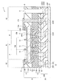
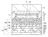
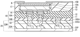
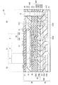
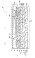
- FIG. 1 schematically shows a cross-sectional configuration of a light receiving element (light receiving element 1) according to the first embodiment of the present disclosure.
- the light receiving element 1 is applied to, for example, an infrared sensor using a compound semiconductor material such as a group III-V semiconductor, and is, for example, visible region (eg, 380 nm or more and less than 780 nm) to short infrared region (eg, 780 nm or more)
- a light having a wavelength of less than 2400 nm) has a photoelectric conversion function.
- the light receiving element 1 is provided with, for example, a plurality of light receiving unit areas (pixels P) two-dimensionally arranged.
- FIG. 1 shows a cross-sectional configuration of a portion corresponding to three pixels P.
- the light receiving element 1 has a laminated structure of an element substrate 10 and a circuit substrate 20.
- One surface of the element substrate 10 is a light incident surface (light incident surface S1), and the surface (the other surface) opposite to the light incident surface S1 is a bonding surface (bonded surface S2) with the circuit substrate 20.
- the element substrate 10 has a configuration in which an interlayer insulating film 18 (18B, 18A), a second contact layer 12, a photoelectric conversion layer 13, a first contact layer 14, and a first electrode 15 are stacked in this order from the circuit substrate 20 side. Have.
- the second contact layer 12, the photoelectric conversion layer 13, and the first contact layer 14 constitute a photoelectric conversion unit 10S common to a plurality of pixels P, and the light of the photoelectric conversion unit 10S A first electrode 15 having a light shielding property is provided between a plurality of adjacent pixels P on the incident surface S1 side.
- element substrate 10 has interlayer insulating films 18B and 18A, second contact layer 12, photoelectric conversion layer 13, first contact layer 14, and first electrode 15 in this order from the position near circuit substrate 20. doing.
- the interlayer insulating film 18 is provided with a wiring layer 10W including the second electrode 11.
- the opposite surface and the end surface (side surface) of the photoelectric conversion unit 10S to the wiring layer 10W are covered with the insulating film 16.
- the circuit board 20 has a wiring layer 20W in contact with the bonding surface S2 of the element substrate 10, and a support substrate 21 facing the element substrate 10 with the wiring layer 20W in between.
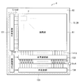
- a pixel region R1 which is a light receiving region is provided in the central portion of the element substrate 10, and the photoelectric conversion unit 10S is disposed in the pixel region R1.
- the area where the photoelectric conversion unit 10S is provided is the pixel area R1.
- a peripheral region R2 surrounding the pixel region R1 is provided outside the pixel region R1.
- a buried layer 17 is provided together with the insulating film 16.
- the first electrode 15 is provided between the plurality of adjacent pixels P, and is formed in a so-called grid shape in plan view, for example.
- the light receiving element 1 of the present embodiment light is incident to the photoelectric conversion unit 10S through the first contact layer 14 from between the first electrodes 15 provided between the pixels P. It has become.
- the signal charges photoelectrically converted by the photoelectric conversion unit 10S move through the wiring layer 10W and are read out by the circuit board 20. The configuration of each part will be described below.
- the wiring layer 10W has, for example, the second electrode 11 and the contact electrodes 18EA and 18EB in the interlayer insulating film 18 (18A and 18B).
- the interlayer insulating film 18 (18A, 18B) is provided across the pixel region R1 and the peripheral region R2 and has a bonding surface S2 with the circuit substrate 20.
- the bonding surface S2 in the pixel region R1 and the bonding surface in the peripheral region R2 form the same plane.
- the interlayer insulating films 18A and 18B have a laminated structure, and for example, the interlayer insulating film 18A is disposed on the second contact layer 12 side, and the interlayer insulating film 18B is disposed on the circuit board 20 side.
- the interlayer insulating films 18A and 18B are made of, for example, an inorganic insulating material.
- the inorganic insulating material examples include silicon nitride (SiN), aluminum oxide (Al 2 O 3 ), silicon oxide (SiO 2 ) and hafnium oxide (HfO 2 ).
- the interlayer insulating films 18A and 18B may be formed using different inorganic insulating materials, or may be formed using the same inorganic insulating material.
- the second electrode 11 is an electrode (anode) to which a voltage for reading out the signal charge (a hole or an electron, hereinafter the signal charge is described as a hole for convenience) generated in the photoelectric conversion layer 13 is supplied. And is provided for each pixel P in the pixel region R1.
- the second electrode 11 provided in the wiring layer 10W is in contact with the second contact layer 12 of the photoelectric conversion unit 10S through the connection holes of the interlayer insulating film 18A and the insulating film 16.
- the adjacent second electrodes 11 are electrically separated by the interlayer insulating film 18 B and the insulating film 16.
- the second electrode 11 is made of, for example, titanium (Ti), tungsten (W), titanium nitride (TiN), platinum (Pt), gold (Au), germanium (Ge), palladium (Pd), zinc (Zn), nickel (Ni) and any one of aluminum (Al), or an alloy containing at least one of them.
- the second electrode 11 may be a single film of such a constituent material, or may be a laminated film in which two or more types are combined.
- the second electrode 11 is formed of a laminated film of titanium and tungsten.
- the contact electrode 18EA is for electrically connecting the second electrode 11 and the circuit board 20, and is provided for each pixel P in the pixel region R1.
- the adjacent contact electrodes 18EA are electrically separated by the interlayer insulating film 18B.
- the contact electrode 18EB is for electrically connecting the first electrode 15 and a wiring (wiring 22CB described later) of the circuit board 20, and is disposed in the peripheral region R2.
- the contact electrode 18EB is formed, for example, in the same process as the contact electrode 18EA.
- the contact electrodes 18EA and 18EB are made of, for example, copper (Cu) pads, and are exposed to the bonding surface S2.
- the photoelectric conversion unit 10S includes, for example, the second contact layer 12, the photoelectric conversion layer 13, and the first contact layer 14 from a position close to the wiring layer 10W.
- the second contact layer 12, the photoelectric conversion layer 13, and the first contact layer 14 have, for example, substantially the same planar shape.
- the second contact layer 12 is provided, for example, in common to all the pixels P, and is disposed between the insulating film 16 and the photoelectric conversion layer 13.
- the second contact layer 12 is for electrically separating the adjacent pixels P, and the second contact layer 12 is provided with, for example, a plurality of diffusion regions 12A.
- a compound semiconductor material having a band gap larger than the band gap of the compound semiconductor material forming the photoelectric conversion layer 13 it is also possible to suppress the dark current.
- n-type InP indium phosphorus
- the diffusion regions 12A provided in the second contact layer 12 are disposed apart from each other.
- the diffusion region 12A is disposed for each pixel P, and the second electrode 11 is connected to each diffusion region 12A.
- the diffusion region 12A is for reading out the signal charge generated in the photoelectric conversion layer 13 for each pixel P, and includes, for example, a p-type impurity. Examples of p-type impurities include Zn (zinc).
- a pn junction interface is formed between the diffusion region 12A and the second contact layer 12 other than the diffusion region 12A, and adjacent pixels P are electrically separated.
- the diffusion region 12A is provided, for example, in the thickness direction of the second contact layer 12, and is also provided in a part of the photoelectric conversion layer 13 in the thickness direction.
- the photoelectric conversion layer 13 between the second electrode 11 and the first electrode 15, more specifically, between the second contact layer 12 and the first contact layer 14 is, for example, common to all the pixels P. It is provided.
- the photoelectric conversion layer 13 absorbs light of a predetermined wavelength to generate a signal charge, and is made of, for example, a compound semiconductor material such as an i-type III-V group semiconductor. Examples of compound semiconductor materials constituting the photoelectric conversion layer 13 include InGaAs (indium gallium arsenide), InAsSb (indium arsenide antimony), InAs (indium arsenide), InSb (indium antimony) and HgCdTe (mercury cadmium telluride). It can be mentioned.
- the photoelectric conversion layer 13 may be made of Ge (germanium). In the photoelectric conversion layer 13, for example, photoelectric conversion of light of wavelengths from the visible region to the short infrared region is performed.
- the first contact layer 14 is provided in common to all the pixels P, for example.
- the first contact layer 14 is provided between the photoelectric conversion layer 13 and the first electrode 15 and is in contact with these.
- the first contact layer 14 is a region to which the charge discharged from the first electrode 15 moves, and is made of, for example, a compound semiconductor containing an n-type impurity.
- n-type InP indium phosphorus
- the thickness of the first contact layer 14 is, for example, 20 nm or more and 1000 nm or less.
- the first electrode 15 has a configuration in which the cap layer 15A and the light shielding film 15B are stacked in this order, and, for example, between the adjacent pixels P on the first contact layer 14 (light incident surface side) Provided in The first electrode 15 is for discharging a charge not used as a signal charge among the charges generated in the photoelectric conversion layer 13 (cathode). For example, when a hole is read out from the second electrode 11 as a signal charge, electrons are discharged through the first electrode 15. As described above, by providing the first electrode 15 in a lattice shape, the resistance for taking out electrons is reduced, and the demand for lowering the resistance to the first contact layer 14 is reduced, and the first contact layer 14 is thinned. Is possible.
- the cap layer 15A is made of a semiconductor material that can be epitaxially grown on the first contact layer 14 of the photoelectric conversion unit 10S, and, for example, InGaAs or InAsSb can be used.
- the light shielding film 15B is provided extending from the pixel region R1 to the peripheral region R2, and is provided on the cap layer 15A in the pixel region R1. That is, the light shielding film 15B is provided, for example, in a lattice shape between adjacent pixels P in the pixel region R1.
- the light shielding film 15B is made of a metal film having a light shielding property. Specifically, a tungsten (W) film, a copper (Cu) film, an aluminum (Al) film, a silver (Ag) film, or the like can be used. These metal films are stacked on the cap layer 15A via a barrier metal film such as a titanium (Ti) film or a titanium nitride (TiN) film.
- the light shielding film 15B has a laminated structure in which the barrier metal film and the metal film are sequentially laminated from the cap layer 15A side. Thus, an ohmic contact is formed between the cap layer 15A and the light shielding film 15B.
- the thickness of the light shielding film 15B is preferably, for example, 50 nm or more and 1000 nm or less, and the thickness of the barrier metal film is, for example, 10 nm or more and 500 nm or less, and the thickness of the metal film is, for example, 50 nm or more and 1000 nm or less.
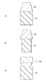
- the cross-sectional shape of the first electrode 15 is illustrated in FIG. 1 as a rectangular shape having the same side surface in which the cap layer 15A and the light shielding film 15B are continuous, the cross-sectional shape is not limited thereto.
- an inclination may be formed on the side surface of the light shielding film 15B, and as shown in FIG. 2B, the side surface of the light shielding film 15B has an inclination.
- the cap layer 15A may be etched inside the bottom of the light shielding film 15B.
- the cap layer 15A and the metal film portion may have the same side surface, and only the barrier metal film between the cap layer 15A and the metal film may be etched inward. .
- the first electrode 15 is formed by patterning the light shielding film 15B by dry etching, and then patterning the cap layer 15A by wet etching using the light shielding film 15B as a metal mask.
- the cross-sectional shape of the cap layer 15A (for example, N + InGaAs layer) patterned in a lattice shape has different characteristics depending on the crystal plane orientation.
- a 100-faced InGaAs / InP crystal is processed into an inverse taper in the (011) plane cross-sectional direction and a forward taper in the direction rotated by 90 ° with respect to the (011) plane.
- a passivation film is provided on the surface of the light receiving element 1.
- the passivation film may have an antireflective function.
- silicon nitride (SiN), aluminum oxide (Al 2 O 3 ), silicon oxide (SiO 2 ), tantalum oxide (Ta 2 O 3 ) or the like can be used.
- the insulating film 16 is provided between the second contact layer 12 and the wiring layer 10W, and the bottom and end face of the second contact layer 12, the end face of the photoelectric conversion layer 13, the end face of the first contact layer 14 and the cap layer 15A. And covers the light shielding film 15B in the peripheral region R2.
- the insulating film 16 includes, for example, an oxide such as silicon oxide (SiO x ) or aluminum oxide (Al 2 O 3 ).
- the insulating film 16 may be configured as a laminated structure including a plurality of films.
- the insulating film 16 may be made of, for example, a silicon (Si) -based insulating material such as silicon oxynitride (SiON), carbon-containing silicon oxide (SiOC), silicon nitride (SiN), and silicon carbide (SiC).
- Si silicon oxynitride
- SiOC carbon-containing silicon oxide
- SiN silicon nitride
- SiC silicon carbide
- the embedded layer 17 is for filling a step between the temporary substrate (a temporary substrate 73 in FIG. 3B described later) and the photoelectric conversion unit 10S in the manufacturing process of the light receiving element 1. Although details will be described later, in the present embodiment, since the embedded layer 17 is formed, the occurrence of defects in the manufacturing process due to the step between the photoelectric conversion unit 10S and the temporary substrate 73 can be suppressed.
- the embedded layer 17 is provided between the wiring layer 10W and the light shielding film 15B, and has a thickness equal to or greater than, for example, the thickness of the photoelectric conversion unit 10S.
- the buried layer 17 is provided to surround the photoelectric conversion unit 10S, a region (peripheral region R2) around the photoelectric conversion unit 10S is formed. Thereby, the bonding surface S2 with the circuit board 20 can be provided in the peripheral region R2.
- the thickness of the embedded layer 17 may be reduced as long as the bonding surface S2 is formed in the peripheral region R2, but the embedded layer 17 covers the photoelectric conversion unit 10S in the thickness direction, and the entire end face of the photoelectric conversion unit 10S. Is preferably covered by the embedded layer 17.
- the embedded layer 17 covers the entire end surface of the photoelectric conversion unit 10S through the insulating film 16 to effectively suppress the entry of moisture into the photoelectric conversion unit 10S.
- the surface of the embedded layer 17 on the bonding surface S2 side is planarized, and in the peripheral region R2, the wiring layer 10W is provided on the surface of the planarized embedded layer 17.
- an inorganic insulating material such as silicon oxide (SiO X ), silicon nitride (SiN), silicon oxynitride (SiON), carbon-containing silicon oxide (SiOC) and silicon carbide (SiC) is used.
- the embedded layer 17 is provided with a through electrode 17V.
- the through electrode 17V is for connecting the first electrode 15 and the wiring layer 20W provided on the circuit board 20.
- One of the through electrodes 17V is connected to the first electrode 15, and the other of the through electrodes 17V penetrates the interlayer insulating film 18A and is connected to the contact electrode 18EB.
- the contact electrode 18EB is provided in the peripheral region R2 of the interlayer insulating film 18B, and is electrically connected to the wiring 22CB provided in the peripheral region R2 in the wiring layer 20W.
- the support substrate 21 is for supporting the wiring layer 20W, and is made of, for example, silicon (Si).
- the wiring layer 20W has, for example, the contact electrodes 22EA and 22EB, the pixel circuit 22CA, the wiring 22CB, and the pad electrode 22P in the interlayer insulating film 22 (22A and 22B).
- the interlayer insulating films 22A and 22B are made of, for example, an inorganic insulating material. Examples of the inorganic insulating material include silicon nitride (SiN), aluminum oxide (Al 2 O 3 ), silicon oxide (SiO 2 ) and hafnium oxide (HfO 2 ).
- the interlayer insulating films 22A and 22B may be formed using different inorganic insulating materials, or may be formed using the same inorganic insulating material.
- the contact electrode 22EA is provided, for example, in the pixel region R1 for electrically connecting the second electrode 11 and the pixel circuit 22CA, and is in contact with the contact electrode 18EA at the bonding surface S2 of the element substrate 10.
- the adjacent contact electrodes 22EA are electrically separated by the interlayer insulating films 22A and 22B.
- the contact electrode 22EB is provided, for example, in the peripheral region R2 and is for electrically connecting the first electrode 15 and the wiring 22CB of the circuit board 20, and is in contact with the contact electrode 18EB at the bonding surface S2 of the element substrate 10. ing.
- the contact electrode 22EB is formed, for example, in the same process as the contact electrode 22EA.
- the through electrodes 17V may be connected to the wirings 22CB without providing the contact electrodes 18EB and 22EB.
- the contact electrodes 22EA and 22EB are made of, for example, copper (Cu) pads, and are exposed on the surface of the circuit board 20 facing the element substrate 10. That is, for example, CuCu bonding is performed between the contact electrode 18EA and the contact electrode 22EA, and between the contact electrode 18EB and the contact electrode 22EB.
- Cu copper
- the pixel circuit 22CA is provided, for example, for each pixel P in the pixel region R1 and is connected to the contact electrode 22EA.
- the pixel circuit 22CA constitutes an ROIC.
- the wiring 22CB is provided, for example, in the peripheral region R2, connected to the contact electrode 22EB, and connected to, for example, a predetermined potential.
- one of the charges generated in the photoelectric conversion layer 13 (for example, a hole) is read from the second electrode 11 to the pixel circuit 22CA via the contact electrodes 18EA and 22EA, and is generated in the photoelectric conversion layer 13
- the other of the charges (for example, electrons) is discharged from the first electrode 15 to a predetermined potential through the through electrode 17V and the contact electrodes 18EB and 22EB.
- the pad electrode 22P is for electrically connecting to the outside.
- the light receiving element 1 is provided with an opening H which penetrates the element substrate 10 and reaches the pad electrode 22P, and is electrically connected to the outside through the opening H.
- the connection is made by, for example, a method such as wire bonding or bumps.
- the light receiving element 1 can be manufactured, for example, as follows. 3A to 8C show the manufacturing process of the light receiving element 1 in the order of steps.
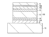
- a buffer layer 74B made of n-type InP, a stopper layer 74S made of i-type InGaAs, a photoelectric conversion portion 10S, and a cap made of i-type InGaAs Layers 15A are formed by epitaxial growth in this order.
- the diameter of the growth substrate 71 is, for example, 6 inches or less.
- the photoelectric conversion unit 10S for example, the second contact layer 12 made of n-type InP, the photoelectric conversion layer 13 made of i-type or n-type InGaAs, and the first contact layer 14 made of n-type InP are formed in this order. Do.
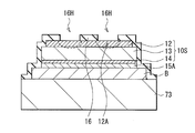
- the growth substrate 71 is bonded to the large-diameter temporary substrate 73 with the adhesive layer B interposed therebetween.
- the cap layer 15A is interposed between the adhesive layer B and the first contact layer 14.
- the temporary substrate 73 for example, a silicon (Si) substrate having a larger diameter than the growth substrate 71 is used.
- the diameter of the temporary substrate 73 is, for example, 8 inches to 12 inches.
- the bonding of the growth substrate 71 to the temporary substrate 73 may be performed by plasma activation bonding, normal temperature bonding, bonding using an adhesive (adhesive bonding), or the like.
- the wafer-shaped photoelectric conversion unit 10S is bonded to the temporary substrate 73.
- the photoelectric conversion unit 10S is not limited to a wafer but may be fragmented into a chip.
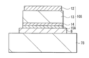
- the growth substrate 71 After bonding the growth substrate 71 in which the photoelectric conversion unit 10S is formed to the temporary substrate 73, as shown in FIG. 4A, the growth substrate 71 is removed.
- the growth substrate 71 can be removed by mechanical grinding, CMP (Chemical Mechanical Polishing), wet etching, dry etching or the like.
- the positional deviation of the photoelectric conversion unit 10S with respect to the temporary substrate 73 is corrected.
- the positional deviation of the photoelectric conversion unit 10S is corrected using, for example, photolithography and etching.
- a resist (resist PR) is formed on the photoelectric conversion unit 10S, and the photoelectric conversion unit 10S is appropriately etched.
- the etching can be dry etching or wet etching. Thus, unnecessary portions of the photoelectric conversion unit 10S can be removed, and the photoelectric conversion unit 10S can be left only in the defined region (pixel region R1) of the temporary substrate 73.
- the insulating film 16 is formed on the entire surface of the temporary substrate 73. Subsequently, the diffusion region 12A is formed for each pixel P in the photoelectric conversion unit 10S. Thus, element isolation is achieved.
- the insulating film 16 is used as a hard mask for forming the diffusion region 12A. Specifically, after a mask having a predetermined shape is formed on the second contact layer 12, an opening 16H is formed in the insulating film 16 by etching. After that, resist stripping is performed, and vapor phase diffusion of p-type impurities is performed using the insulating film 16 as a hard mask.
- diffusion region 12A is formed in the selective region.
- the diffusion region 12A may be formed by ion implantation or the like using a resist mask.
- the diffusion region 12A is formed in the photoelectric conversion unit 10S provided on the large-diameter temporary substrate 73, the pixel P can be miniaturized.
- the diffusion region 12A is formed in the photoelectric conversion unit 10S, as shown in FIG. 5B, an insulating material is formed on the entire surface of the temporary substrate 73, and then planarized by, for example, CMP.
- the buried layer 17 that forms the same plane as the upper surface (the surface farthest from the temporary substrate 73) of the photoelectric conversion unit 10S is formed around the photoelectric conversion unit 10S (peripheral region R2).
- the diffusion region 12A and the buried layer 17 may be formed in the reverse order, and after the positional deviation of the photoelectric conversion unit 10S with respect to the temporary substrate 73 is corrected, the diffusion region 12A and the buried layer 17 are You may form in this order.
- the wiring layer 10W including the second electrode 11 is formed on the photoelectric conversion unit 10S.
- an insulating material is formed on the entire surface of the photoelectric conversion unit 10S and the embedded layer 17, and then an opening is formed.
- a laminated film of titanium (Ti) / tungsten (W) is formed in this opening by a chemical vapor deposition (CVD) method, a physical vapor deposition (PVD) method, an atomic layer deposition (ALD) method, an evaporation method, or the like.
- CVD chemical vapor deposition
- PVD physical vapor deposition
- ALD atomic layer deposition
- the laminated film is formed by patterning using photolithography and etching.
- the second electrode 11 is formed.
- an insulating material is further deposited to cover the second electrode 11, and then planarized by, eg, CMP to form an interlayer insulating film 18A.
- an insulating material is formed on the interlayer insulating film 18A, planarized by, eg, CMP to form the interlayer insulating film 18B, and then, as shown in FIG. 6A, on the photoelectric conversion unit 10S (pixel region R1) and An opening 18H1 and an opening 18H2 are formed in the region (peripheral region R2) other than on the photoelectric conversion unit 10S. A part of the second electrode 11 is exposed at the bottom surface of the opening 18H1 formed on the photoelectric conversion unit 10S.
- a contact electrode is formed by polishing the surface of the copper film using a CMP method, for example.
- a CMP method for example.
- the wiring layer 10W having the second electrode 11 and the contact electrodes 18EA and 18EB is formed.
- the wiring layer 10W is formed on the large-diameter temporary substrate 73, various devices for large-diameter substrates can be used.
- the photoelectric conversion portion It is possible to suppress the characteristic deterioration of 10S and the occurrence of film peeling and the like.
- the circuit board 20 is bonded to the temporary substrate 73 with the wiring layer 10W in between. At this time, the wiring layer 20W is formed on the circuit board 20 in advance.
- the wiring layer 20W of the circuit board 20 has the contact electrodes 22EA and 22EB of a pad structure.
- the contact electrodes 22EA and 22EB of the wiring layer 20W and the wiring The CuCu junction is performed with the contact electrodes 18EA and 18EB of the layer 10W.
- junction surface S2 in which contact electrode 18EA and contact electrode 22EA are joined is formed, and in peripheral region R2, junction surface S2 in which contact electrode 18EB and contact electrode 22EB are joined is It is formed.
- the peripheral region R2 of the element substrate 10 is also bonded to the circuit substrate 20.
- the temporary substrate 73 is removed.
- the temporary substrate 73 can be removed by using, for example, mechanical grinding, wet etching or dry etching.
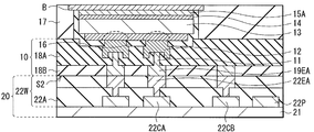
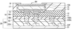
- the adhesive layer B on the pixel region R1 is removed by wet etching, for example, to form an opening BH.
- wet etching of the adhesive layer B for example, HF (Hydrogen Fluoride) or BHF (Buffered Hydrogen Fluoride) can be used.
- HF Hydrogen Fluoride
- BHF Buffered Hydrogen Fluoride
- the light shielding film 15B is formed on the entire surface of the embedded layer 17, the adhesive layer B, and the cap layer 15A using a sputtering method or a CVD method.
- a mask having a predetermined shape is formed on the light shielding film 15B.
- the light shielding film 15B is patterned in a grid shape using dry etching. At this time, ion damage and light damage due to dry etching are absorbed by the cap layer 15A, and damage to the first contact layer 14 is reduced.
- the cap layer 15A is patterned by wet etching using the light shielding film 15B patterned in a lattice shape as a mask.
- a passivation film (not shown) is formed on the first contact layer 14, the first electrode 15, and the buried layer 17 exposed by removing the cap layer 15A, and then penetrates the buried layer 17.
- An electrode 17V is formed to electrically connect the first electrode 15 and the circuit board 20.
- an opening H which penetrates the element substrate 10 and reaches the pad electrode 22P of the circuit substrate 20 is formed. Thereby, the light receiving element 1 shown in FIG. 1 is completed.
- a light receiving element constituting an infrared sensor is provided with a transparent electrode on the light incident surface side, and this transparent electrode is responsible for reading out charges (holes or electrons) generated by photoelectric conversion.
- the transparent electrode can not be used in the light receiving element using a compound semiconductor for the photoelectric conversion layer. In that case, the compound is used to reduce the wiring resistance for charge readout. It is necessary to thicken the semiconductor layer (for example, n + InP layer). However, the n + InP layer has a problem that absorption of visible light is high and the sensitivity in the visible region is lowered.
- the first electrode 15 having a light shielding property is provided between the adjacent pixels P on the light incident surface S1 side.
- the first electrode 15 has a laminated structure of a cap layer 15A and a light shielding film 15B formed using, for example, a metal film.
- the photoelectric conversion portion 10S (specifically, the first contact layer 14) at the time of patterning of the metal film constituting the light shielding film 15B. It is possible to prevent damage to).
- the contact resistance between the photoelectric conversion unit 10S (specifically, the first contact layer 14) and the first electrode 15 can be reduced. Furthermore, by forming the first electrode 15 in a lattice shape, for example, the wiring resistance of the first electrode 15 that discharges electrons, for example, is reduced. As a result, formation of the transparent electrode on the light incident surface S1 side becomes unnecessary, and thickening of the first contact layer 14 constituting the photoelectric conversion unit 10S becomes unnecessary, and absorption of visible light by the first contact layer 14 becomes unnecessary. Is reduced.
- the first electrode 15 in which the cap layer 15A and the light shielding film 15B are stacked in a lattice shape is provided between the adjacent pixels P on the light incident surface S1 side.
- the formation of the transparent electrode and the thickening of the first contact layer 14 become unnecessary.
- damage to the photoelectric conversion part (specifically, the first contact layer 14) at the time of patterning of the light shielding film 15B is reduced.
- the sensitivity can be improved.
- the light shielding film 15B has a laminated structure of a barrier metal and a metal film, and is laminated on the cap layer 15A in this order.
- an ohmic contact is formed between the cap layer 15A and the light shielding film 15B. Accordingly, the contact resistance between the photoelectric conversion unit 10S (specifically, the first contact layer 14) and the first electrode 15 can be further reduced, and the sensitivity can be further improved.
- patterning of the cap layer 15A is performed using wet etching, so damage to the first contact layer 14 can be reduced. Therefore, it is possible to reduce the occurrence of dark current.
- FIG. 9 schematically shows a cross-sectional configuration of a light receiving element (light receiving element 1A) according to a modified example (modified example 1) of the present disclosure.
- the light receiving element 1A is applied to, for example, an infrared sensor using a compound semiconductor material such as a group III-V semiconductor in the same manner as the light receiving element 1 in the above embodiment. It has a photoelectric conversion function for light of a wavelength of 780 nm or less to short infrared region (eg, 780 nm or more and less than 2400 nm).
- the light receiving element 1A of this modification has a color filter having color filters of, for example, red (31R), green (31G), and blue (31B) on each pixel P disposed in the pixel region R1 on the light incident surface side.
- the point that the (CF) layer 31 and the on-chip lens 32 are provided in this order is different from the above embodiment.
- the present modification can be applied not only to the light receiving element 1 in the first embodiment but also to the light receiving element 2 and the light receiving elements 3A to 3E described later.
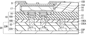
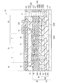
- FIG. 10 schematically shows a cross-sectional configuration of a light receiving element (light receiving element 2) according to a modification (modification 2) of the present disclosure.
- the light receiving element 2 is applied to, for example, an infrared sensor using a compound semiconductor material such as a group III-V semiconductor in the same manner as the light receiving element 1 in the above embodiment. It has a photoelectric conversion function for light of a wavelength of 780 nm or less to short infrared region (eg, 780 nm or more and less than 2400 nm).
- the light receiving element 2 is provided with, for example, a plurality of light receiving unit areas (pixels P) two-dimensionally arranged. In FIG. 10, the cross-sectional configuration of a portion corresponding to three pixels P is shown.
- the light receiving element 2 has a laminated structure of the element substrate 10 and the circuit board 20 as in the above embodiment.
- One surface of the element substrate 10 is a light incident surface (light incident surface S1), and the surface (the other surface) opposite to the light incident surface S1 is a bonding surface (bonded surface S2) with the circuit substrate 20.
- the interlayer insulating film 18 (18B, 18A), the second contact layer 12, the photoelectric conversion layer 13, the first contact layer 14 and the first electrode 15 are stacked in this order, and for the plurality of pixels P.
- the present embodiment has a configuration in which the first electrodes 35 (35A, 35B) having a light shielding property are provided between the plurality of pixels P on the light incident surface S1 side of the photoelectric conversion unit 10S.
- the first electrode 35A is provided on the first contact layer 14, for example, between a plurality of adjacent pixels P in a so-called lattice shape and provided so as to penetrate the passivation film 19.
- the first electrode 35A is preferably formed using a metal that is conductive and that can form an ohmic contact with the first contact layer 14.
- the first electrode 35A may have either a single-layer structure or a laminated structure, and preferably has a configuration in which, for example, a barrier metal film and a metal film are stacked in this order from the first contact layer 14 side.
- As the barrier metal film a titanium (Ti) film, a titanium nitride (TiN) film or the like can be used.
- tungsten (W) film As the metal film, a tungsten (W) film, a copper (Cu) film, an aluminum (Al) film, a silver (Ag) film, or the like can be used. Thereby, an ohmic contact is formed between the first contact layer 14 and the first electrode 15.
- the first electrode 35B is electrically connected to the wiring 22CB in the peripheral region R2 via the through electrode 17V and the contact electrodes 18EB and 22EB.
- the wiring 22CB is connected to, for example, a predetermined potential as described above.
- the potential of the wiring 2CB can be set arbitrarily.
- the first electrode 35B may be directly connected to an electrode outside the chip without the through electrode 17V or the like.
- the first electrode 35 is formed between adjacent pixels P, for example, in a lattice shape in plan view, so the wiring resistance of the first electrode 35 is Reduced. Therefore, the first contact layer 14 can be thinned, and the sensitivity can be improved.
- the manufacturing process can be shortened as compared with the above embodiment. Light leakage from adjacent pixel regions is further reduced. That is, the light shielding performance by the first electrode 35 is further improved, and the occurrence of color mixing can be further reduced.
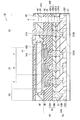
- FIG. 11 schematically illustrates a cross-sectional configuration of a light receiving element (light receiving element 3A) according to the second embodiment of the present disclosure.
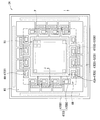
- FIG. 12 schematically shows a plan configuration of the entire light receiving element 3A shown in FIG.
- the light receiving element 3A is applied to, for example, an infrared sensor using a compound semiconductor material such as a group III-V semiconductor, and is, for example, visible region (eg, 380 nm or more and less than 780 nm) to short infrared region (eg, 780 nm or more)
- a light having a wavelength of less than 2400 nm) has a photoelectric conversion function.
- the light receiving element 3A is provided with, for example, a plurality of light receiving unit areas (pixels P) two-dimensionally arranged.
- FIG. 11 shows a cross-sectional configuration of a portion corresponding to three pixels P.
- the light receiving element 3A has a laminated structure of an element substrate 40 and a circuit substrate 50.
- One surface of the element substrate 40 is a light incident surface (light incident surface S1), and the surface (the other surface) opposite to the light incident surface S1 is a bonding surface (bonded surface S2) with the circuit substrate 50.
- the element substrate 40 has a configuration in which the interlayer insulating film 48 (48B, 48A), the second contact layer 42, the photoelectric conversion layer 43, the first contact layer 44, and the first electrode 45 are stacked in this order from the circuit substrate 50 side.
- the second contact layer 42, the photoelectric conversion layer 43, and the first contact layer 44 constitute a photoelectric conversion unit 40S common to the plurality of pixels P.
- the first electrode 45 common to each pixel is provided on the light incident surface S1 side of the photoelectric conversion unit 40S via the insulating layer 49.
- the element substrate 40 includes, in order from the position close to the circuit substrate 50, the wiring layer 40W including the interlayer insulating films 48B and 48A and the second electrode 41, the photoelectric conversion portion 40S, and the first electrode 45 in this order.
- the opposite surface and the end surface (side surface) of the photoelectric conversion unit 40S to the wiring layer 40W are covered with the insulating film 46.
- the circuit board 50 has a wiring layer 50W in contact with the bonding surface S2 of the element substrate 40, and a support substrate 51 facing the element substrate 40 with the wiring layer 50W in between.
- a pixel area R1 which is a light receiving area is provided, and the photoelectric conversion unit 40S is disposed in the pixel area R1.
- the area in which the photoelectric conversion unit 40S is provided is the pixel area R1.
- a peripheral region R2 surrounding the pixel region R1 is provided outside the pixel region R1.
- the embedded layer 47 is provided together with the insulating film 46.
- the first electrode 45 is provided on the photoelectric conversion unit 40S via the insulating layer 49. The signal charges photoelectrically converted by the photoelectric conversion unit 40S move through the wiring layer 40W and are read out by the circuit board 50. The configuration of each part will be described below.
- the wiring layer 40W has, for example, the second electrode 41 and the contact electrodes 48EA and 48EB in the interlayer insulating films 48 (48A and 48B).
- the interlayer insulating film 48 (48A, 48B) is provided over the pixel region R1 and the peripheral region R2 and has a bonding surface S2 with the circuit substrate 50.
- the bonding surface S2 in the pixel region R1 and the bonding surface in the peripheral region R2 form the same plane.
- the interlayer insulating films 48A and 48B have a laminated structure, and for example, the interlayer insulating film 48A is disposed on the second contact layer 42 side, and the interlayer insulating film 48B is disposed on the circuit board 50 side.
- the interlayer insulating films 48A and 48B are made of, for example, an inorganic insulating material.
- the inorganic insulating material examples include silicon nitride (SiN), aluminum oxide (Al 2 O 3 ), silicon oxide (SiO 2 ) and hafnium oxide (HfO 2 ).
- the interlayer insulating films 48A and 48B may be formed using different inorganic insulating materials, or may be formed using the same inorganic insulating material.
- the second electrode 41 is an electrode (anode) to which a voltage for reading out the signal charge (a hole or an electron, hereinafter the signal charge is described as a hole for convenience) generated in the photoelectric conversion layer 43 is supplied. And is provided for each pixel P in the pixel region R1.
- the second electrode 41 provided in the wiring layer 40W is in contact with the photoelectric conversion unit 40S (more specifically, the second contact layer 42 described later) through the connection holes of the interlayer insulating film 18A and the insulating film 46. .
- the adjacent second electrodes 41 are electrically separated by the interlayer insulating film 48 B and the insulating film 46.
- the second electrode 41 is made of, for example, titanium (Ti), tungsten (W), titanium nitride (TiN), platinum (Pt), gold (Au), germanium (Ge), palladium (Pd), zinc (Zn), nickel (Ni) and any one of aluminum (Al), or an alloy containing at least one of them.
- the second electrode 41 may be a single film of such a constituent material, or may be a laminated film combining two or more types.
- the second electrode 41 is formed of a laminated film of titanium and tungsten.
- the contact electrode 48EA is for electrically connecting the second electrode 41 and the circuit board 50, and is provided for each pixel P in the pixel region R1.
- the adjacent contact electrodes 48EA are electrically separated by the interlayer insulating film 48B.
- the contact electrode 48EB is for electrically connecting the first electrode 45 and the wiring (wiring 52CB described later) of the circuit board 50, and is disposed in the peripheral region R2.
- the contact electrode 48EB is formed, for example, in the same step as the contact electrode 48EA.
- the contact electrodes 48EA and 48EB are made of, for example, copper (Cu) pads, and are exposed to the bonding surface S2.
- the photoelectric conversion unit 40S includes, for example, the second contact layer 42, the photoelectric conversion layer 43, and the first contact layer 44 from a position close to the wiring layer 40W.
- the second contact layer 42, the photoelectric conversion layer 43, and the first contact layer 44 have substantially the same planar shape.
- the second contact layer 42 is provided, for example, in common to all the pixels P, and is disposed between the insulating film 46 and the photoelectric conversion layer 43.
- the second contact layer 42 is for electrically separating adjacent pixels P, and the second contact layer 42 is provided with, for example, a plurality of diffusion regions 12A.
- a compound semiconductor material having a band gap larger than the band gap of the compound semiconductor material forming the photoelectric conversion layer 43 it is also possible to suppress the dark current.
- n-type InP indium phosphorus
- the diffusion regions 12A provided in the second contact layer 42 are spaced apart from each other.
- the diffusion region 12A is disposed for each pixel P, and the second electrode 41 is connected to each diffusion region 12A.
- the diffusion region 12A is for reading out the signal charge generated in the photoelectric conversion layer 43 for each pixel P, and includes, for example, a p-type impurity. Examples of p-type impurities include Zn (zinc).
- pn junction interface is formed between the diffusion region 12A and the second contact layer 42 other than the diffusion region 12A, and the adjacent pixels P are electrically separated.
- the diffusion region 12A is provided, for example, in the thickness direction of the second contact layer 42, and is also provided in a part of the photoelectric conversion layer 43 in the thickness direction.
- the photoelectric conversion layer 43 between the second electrode 41 and the first electrode 45, more specifically, between the second contact layer 42 and the first contact layer 44 is common to all the pixels P, for example. It is provided.
- the photoelectric conversion layer 43 absorbs light of a predetermined wavelength to generate a signal charge, and is made of, for example, a compound semiconductor material such as an i-type III-V group semiconductor. Examples of the compound semiconductor material constituting the photoelectric conversion layer 43 include InGaAs (indium gallium arsenide), InAsSb (indium arsenide antimony), InAs (indium arsenide), InSb (indium antimony) and HgCdTe (mercury cadmium telluride). It can be mentioned.
- the photoelectric conversion layer 43 may be made of Ge (germanium). In the photoelectric conversion layer 43, for example, photoelectric conversion of light of wavelengths from the visible region to the short infrared region is performed.
- the first contact layer 44 is provided commonly to all the pixels P, for example.
- the first contact layer 44 is provided between the photoelectric conversion layer 43 and the first electrode 45 and is in contact with them.
- the first contact layer 44 is a region through which the charge discharged from the first electrode 45 moves, and is made of, for example, a compound semiconductor containing an n-type impurity.
- n-type InP indium phosphorus
- the thickness of the first contact layer 44 is, for example, 10 nm or more and 300 nm or less.
- the insulating layer 49 is for controlling the carrier concentration of the first contact layer 44, and, for example, a single layer film of silicon oxide (SiO x ), silicon nitride (SiN) and silicon oxynitride (SiON), or a film thereof It is configured as a laminated film.
- the thickness of the insulating layer 49 is, for example, 10 nm or more and 200 nm or less.
- the first electrode 45 has first electrodes 45A and 45B separated from each other.
- the first electrode 45A is provided on the entire surface of the pixel region R1, for example, as an electrode common to all the pixels P.
- the first electrode 45B is provided in the peripheral region R2 and is electrically connected to the first contact layer 44.
- the first electrode 45 (in particular, the first electrode 45B) is for discharging a charge not used as a signal charge among the charges generated in the photoelectric conversion layer 43 (cathode).
- the first electrode 45 is made of, for example, a conductive film capable of transmitting incident light such as infrared light.
- the first electrode 45 for example, a transparent conductive material such as ITO (Indium Tin Oxide) or ITiO (In 2 O 3 -TiO 2 ) can be used.
- the first electrode 45 ⁇ / b> B may be formed using a metal film forming the light shielding film 61 in addition to the transparent conductive material.
- the first electrode 45A does not have an electrical connection with the photoelectric conversion unit 40S.
- one of the first electrodes 45B is electrically connected to the first contact layer 44, and the other is electrically connected to the through electrode 47V.
- One of the through electrodes 47V is connected to the first electrode 45B, and the other penetrates the interlayer insulating film 48A, and is electrically connected to the wiring 52CB and the contact electrode 52EB provided in the peripheral region R2 of the circuit board 50. It is connected to the connected contact electrode 48 EB.
- a hole is read out from the second electrode 41 as a signal charge, electrons are discharged through the first electrode 45 B electrically connected to the first contact layer 44.
- the charge concentration (specifically, the electron) of the surface of the photoelectric conversion unit 40S (specifically, the first contact layer 44) Concentration), which lowers the resistance of the first contact layer 44.
- the charges (electrons) extracted through the low resistance first contact layer 44 are discharged through the first electrode 45B, the through electrode 47V, the contact electrodes 48EB and 52EB, and the wiring 52CB in the peripheral region R2. .
- the first contact layer 44 can be thinned by extracting the charge from the first electrode 45B.
- the insulating film 46 is provided between the second contact layer 42 and the wiring layer 40W, and the end face of the second contact layer 42, the end face of the photoelectric conversion layer 43, the end face of the first contact layer 44, and the end face of the cap layer 15A. And is in contact with the light shielding film 15B in the peripheral region R2.
- the insulating film 46 includes, for example, an oxide such as silicon oxide (SiO x ) or aluminum oxide (Al 2 O 3 ).
- the insulating film 46 may be configured by a laminated structure including a plurality of films.
- the insulating film 46 may be made of, for example, a silicon (Si) -based insulating material such as silicon oxynitride (SiON), carbon-containing silicon oxide (SiOC), silicon nitride (SiN), and silicon carbide (SiC).
- Si silicon oxynitride
- SiOC carbon-containing silicon oxide
- SiN silicon nitride
- SiC silicon carbide
- the embedded layer 47 is for filling a step between the temporary substrate (for example, the temporary substrate 73) and the photoelectric conversion unit 40S in the manufacturing process of the light receiving element 1.
- the buried layer 47 in the peripheral region R2 is provided between the wiring layer 40W and the insulating layer 49, and has a thickness equal to or greater than that of the photoelectric conversion unit 40S, for example.
- a region (peripheral region R2) around the photoelectric conversion unit 40S is formed.
- the bonding surface S2 with the circuit board 50 can be provided in the peripheral region R2.
- the thickness of the embedded layer 47 may be reduced, but the embedded layer 47 covers the photoelectric conversion unit 40S in the thickness direction, and the entire end surface of the photoelectric conversion unit 40S Is preferably covered by the buried layer 47.
- the embedded layer 47 covers the entire end face of the photoelectric conversion unit 40S via the insulating film 16, whereby the penetration of moisture into the photoelectric conversion unit 40S can be effectively suppressed.
- the surface of the embedded layer 47 on the bonding surface S2 side is planarized, and in the peripheral region R2, the wiring layer 40W is provided on the surface of the planarized embedded layer 47.
- an inorganic insulating material such as silicon oxide (SiO x ), silicon nitride (SiN), silicon oxynitride (SiON), carbon-containing silicon oxide (SiOC) and silicon carbide (SiC) is used.
- a through electrode 47V having a light shielding property is provided in the buried layer 47.
- the through electrode 47 ⁇ / b> V is for electrically connecting the first electrode 45 ⁇ / b> B and the wiring 52 ⁇ / b> CB of the circuit board 50.
- One of the through electrodes 47V is connected to the first electrode 45B.
- the other of the through electrodes 47V penetrates the insulating film 46, the embedded layer 47, and the interlayer insulating film 48A, and is connected to a contact electrode 48EB provided in the peripheral region.
- the support substrate 51 of the circuit board 50 is for supporting the wiring layer 50W, and is made of, for example, silicon (Si).
- the wiring layer 50W has, for example, the contact electrodes 52EA and 52EB, the pixel circuit 52CA, the wiring 52CB, and the pad electrode 52P in the interlayer insulating film 52A.
- the interlayer insulating film 52A is made of, for example, an inorganic insulating material. Examples of the inorganic insulating material include silicon nitride (SiN), aluminum oxide (Al 2 O 3 ), silicon oxide (SiO 2 ) and hafnium oxide (HfO 2 ).
- the contact electrode 52EA is for electrically connecting the second electrode 41 and the pixel circuit 52CA, and is in contact with the contact electrode 48EA at the bonding surface S2 of the element substrate 40.
- the adjacent contact electrodes 52EA are electrically separated by the interlayer insulating film 52A.
- the contact electrode 52EB is for electrically connecting the first electrode 45 and the wiring 52CB of the circuit board 50, and is in contact with the contact electrode 48EB at the bonding surface S2 of the element substrate 40.
- the contact electrode 52EB is formed, for example, in the same process as the contact electrode 52EA.
- the through electrode 47V may be connected to the wiring 52CB without providing the contact electrodes 48EB and 52EB.
- the contact electrodes 52EA and 52EB are made of, for example, copper (Cu) pads, and are exposed on the surface of the circuit board 50 facing the element substrate 40. That is, for example, CuCu bonding is performed between the contact electrode 48EA and the contact electrode 52EA, and between the contact electrode 48EB and the contact electrode 52EB.
- the pixel circuit 52CA is provided for each pixel P and is connected to the contact electrode 52EA.
- the pixel circuit 52CA constitutes an ROIC.
- the wiring 52CB connected to the contact electrode 52EB is connected to, for example, a predetermined potential.
- one of the charges generated in the photoelectric conversion layer 43 (for example, the holes) is read from the second electrode 41 to the pixel circuit 52CA via the contact electrodes 48EA and 52EA, and is generated in the photoelectric conversion layer 43.
- the other of the charges (for example, electrons) is discharged from the first electrode 45 to a predetermined potential via the through electrode 47V and the contact electrodes 48EB and 52EB.
- the pad electrode 52P is for electrically connecting to the outside.
- the light receiving element 1 is provided with an opening H which penetrates the element substrate 40 and reaches the pad electrode 52P, and is electrically connected to the outside through the opening H.
- the connection is made by, for example, a method such as wire bonding or bumps.
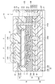
- FIG. 12A schematically shows the entire planar configuration of the light receiving element 3A of the present embodiment.
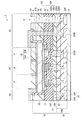
- FIG. 12B schematically shows a cross-sectional configuration of the light receiving element 3A along the line II shown in FIG. 12A.
- FIG. 12C schematically shows a cross-sectional configuration of the light receiving element 3A along line II-II shown in FIG. 12A.
- the light shielding wiring 47EB electrically connected to the first electrode 45 is drawn and electrically connected to the wiring 52CB provided on the circuit board 50. There is.
- the first electrode 45A and the first electrode 45B are mutually independent wirings, and similarly electrically connected to the wirings 52CB1 and 52CB2 independently provided on the circuit board 50. It is desirable that it is done.
- the first electrode 45A is electrically connected (45A to 47EB2) to the wiring 47EB2 at the periphery of the pixel region R1 in the peripheral region R2, and the through electrode is formed. It is electrically connected (47EB2-52CB2) to the wiring 52CB2 provided on the circuit board 50 through the 47V2 and the contact electrodes 48EB2, 52EB2. As shown in FIGS.
- the first electrode 45B is electrically connected to the wiring 47BE1 in the peripheral region R2 outside the connection portion between the first electrode 45A and the wiring 47EB2 (45B-47EB1 Are electrically connected (47EB1-52CB1) with the wiring 52CB1 provided on the outer peripheral portion of the peripheral region R2 on the circuit board 50 through the through electrode 47V1 and the contact electrodes 48EB1 and 52EB1.
- the routing pattern of each wire shown in FIGS. 12A to 12C is an example, and the present invention is not limited to this.
- the InP layer when the N-type compound semiconductor layer is formed of InP, the InP layer has a large band gap and suppresses absorption in the infrared region, so infrared photoelectric conversion efficiency is higher than that of the InGaAs layer. Can be improved. Furthermore, the InP layer can suppress the generation of dark current due to the defect level of the insulating film formed on the surface of the compound semiconductor layer from the size of the band gap. However, the InP layer has a high absorption coefficient with respect to light in the visible light region, and there is a possibility that the sensitivity may be reduced in an image sensor that simultaneously performs photoelectric conversion from visible light to infrared light.
- the insulating layer 49 is provided on the light incident side of the photoelectric conversion unit 40S in which the second contact layer 42, the photoelectric conversion layer 43, and the first contact layer 14 are stacked in this order toward the light incident surface.
- a predetermined voltage can be applied to the first electrode 45, whereby the carrier concentration of the first contact layer 44 can be increased. Therefore, the resistance can be reduced without thickening the first contact layer 44.
- the first electrode 45 is formed on the photoelectric conversion unit 40S via the insulating layer 49.
- the carrier concentration of the first contact layer 44 is increased to reduce the resistance. Therefore, the first contact layer 44 can be thinned, and the sensitivity can be improved.
- FIG. 13 schematically illustrates a cross-sectional configuration of a light receiving element (light receiving element 3B) according to a modification (modification 3) of the present disclosure.
- the light receiving element 3B is applied to, for example, an infrared sensor using a compound semiconductor material such as a group III-V semiconductor, and, for example, For example, light having a wavelength of 380 nm or more and less than 780 nm) to short infrared region (eg, 780 nm or more and less than 2400 nm) has a photoelectric conversion function.
- the light receiving element 3A of this modification is different from the second embodiment in that a light shielding film 61 electrically connected to the first electrode 45 is provided on the first electrode 45.
- the light shielding film 61 is provided around the pixel region R1 as an optical black region (OPB region) for determining a black reference signal, and provided between, for example, adjacent pixels P, for example, formed in a lattice shape in plan view It is a thing. Further, the light shielding film 61 can be used as a parallel wiring of the first electrode 45 by being formed using a conductive material, and the resistance of the first electrode 45 can be reduced. Further, the light shielding film 61 can be made to function as the through electrode 47V (through electrode 61V) in the second embodiment by forming it using a conductive material.
- the light shielding film 61 can be a tungsten (W) film, a copper (Cu) film, an aluminum (Al) film, a silver (Ag) film, or a laminated film of these.
- the first electrode 45 in the pixel region R1 does not have the first electrode 45A having an electrical connection with the photoelectric conversion unit 40S, and And a first electrode 45B electrically connected to the first contact layer 44 of the conversion unit 40S.
- the first contact layer 44 increases the charge concentration (specifically, the electron concentration) on the surface (specifically, the first contact layer 44) of the photoelectric conversion unit 40S. , Reduce resistance.
- the first electrode 45B is electrically connected to the wiring 52CB provided on the circuit board 50 via the through electrode 61V and the contact electrodes 48EB and 52EB.
- a positive potential is applied to the first electrode 45B in the same manner as the first electrode 45A, and charges (electrons) extracted through the low resistance first contact layer 44 are applied to the first electrode 45B. Drained through.
- the first electrode 45 ⁇ / b> B may be formed using a metal film forming the light shielding film 61 in addition to the transparent conductive material.
- the light shielding film 61 is formed between the adjacent pixels P on the first electrode 45 in the pixel region R1, generation of crosstalk between the pixels P is suppressed. It becomes possible. As a result, in addition to the effects of the second embodiment, it is possible to reduce the occurrence of color mixing. In addition, by forming the light shielding film 61 using a metal film, it can be used as parallel wiring of the first electrode 45A. Thus, the resistance of the first electrode 45 can be reduced.
- FIG. 14 schematically illustrates a cross-sectional configuration of a light receiving element (light receiving element 3C) according to a modified example (modification 4) of the present disclosure.
- the light receiving element 3C is applied to, for example, an infrared sensor using a compound semiconductor material such as a group III-V semiconductor, and, for example, For example, light having a wavelength of 380 nm or more and less than 780 nm) to short infrared region (eg, 780 nm or more and less than 2400 nm) has a photoelectric conversion function.
- the light receiving element 3C of this modification is different from the second embodiment in that a light shielding film 61 is provided between the insulating layer 49 and the first electrode 45.
- the through electrode (through electrode 62V) for electrically connecting the first electrode 45 and the circuit board 50 is separately provided.
- one end is the first electrode. It is formed to extend over 45.
- FIG. 15 schematically illustrates a cross-sectional configuration of a light receiving element (light receiving element 3D) according to a modified example (modified example 5) of the present disclosure.
- the light receiving element 3D is applied to an infrared sensor or the like using a compound semiconductor material such as, for example, a III-V semiconductor,
- a compound semiconductor material such as, for example, a III-V semiconductor
- light having a wavelength of 380 nm or more and less than 780 nm) to short infrared region eg, 780 nm or more and less than 2400 nm
- the light receiving element 3D of this modification is different from the second embodiment in that a carrier induction film 63 is provided between the photoelectric conversion unit 40S and the first electrode 45 instead of the insulating layer 49.
- the carrier induction film 63 is for reducing the resistance by increasing the carrier concentration on the surface of the photoelectric conversion unit 40S.
- the carrier induction film 63 desirably lowers the interface state with the photoelectric conversion unit 40S, and for example, preferably has a two-layer structure of an interface state reduction film and a film that promotes carrier induction.
- a silicon oxide (SiO x ) film formed by the ALD method As a film for promoting carrier induction, an insulating film having a positive fixed charge can be mentioned.
- SiN silicon nitride
- SiON silicon oxynitride
- an insulating film having a negative fixed charge can be mentioned, for example, hafnium (Hf), zirconium (Zr), aluminum (Al), tantalum (Ta), titanium (Ti), yttrium (Y) It is preferable to use an insulating film containing at least one element of Y) and lanthanoids.
- FIG. 16 schematically shows a cross-sectional configuration of a light receiving element (light receiving element 3E) according to a modification (modification 6) of the present disclosure.
- the light receiving element 3E is applied to, for example, an infrared sensor using a compound semiconductor material such as a group III-V semiconductor, and, for example, For example, light having a wavelength of 380 nm or more and less than 780 nm) to short infrared region (eg, 780 nm or more and less than 2400 nm) has a photoelectric conversion function.
- the light receiving element 3E of this modification is different from the second embodiment in that the charge is discharged through the first contact layer 44.
- the light receiving element 3E of this modification has a trench 40X narrowed on the side of the first contact layer 44 in the photoelectric conversion unit 40S between the pixel region R1 and the peripheral region R2.
- the holes are read out to the pixel circuit 52CA via the contact electrodes 48EA and 52EA provided in the pixel region R1. Electrons are discharged to the wiring 52CB through the contact electrodes 48EB and 52EB provided in the peripheral region R2 through the N-type region (first contact layer 44).
- the contact electrode 48EB is The first contact layer 44 is electrically connected to the photoelectric conversion unit 40S in the pixel region R1.
- an electric field can be uniformly applied to the N-type region (first contact layer 44) and the P-type region (diffusion region 42A) provided for each pixel.
- FIG. 17 shows the function of the image pickup device 4 using the element structure of the light receiving element 1 (or the light receiving elements 1, 1A, 2, 3A to 3E, hereinafter collectively referred to as the light receiving element 1) described in the above embodiment and the like. It represents a configuration.
- the imaging device 4 is, for example, an infrared image sensor, and includes, for example, a pixel region R1 provided in the light receiving device 1 and a circuit unit 130 for driving the pixel region R1.
- the circuit unit 130 includes, for example, a row scanning unit 131, a horizontal selection unit 133, a column scanning unit 134, and a system control unit 132.
- the pixel region R1 includes, for example, a plurality of pixels P (light receiving elements 1) two-dimensionally arranged in a matrix.
- pixel drive lines Lread for example, row selection lines and reset control lines
- vertical signal lines Lsig are wired for each pixel column.
- the pixel drive line Lread transmits a drive signal for reading out a signal from the pixel P.
- One end of the pixel drive line Lread is connected to an output end corresponding to each row of the row scanning unit 131.
- the row scanning unit 131 is a pixel driving unit configured by a shift register, an address decoder, and the like, and driving each pixel P of the pixel region R1 in, for example, a row unit.
- a signal output from each pixel P of the pixel row selectively scanned by the row scanning unit 131 is supplied to the horizontal selection unit 133 through each of the vertical signal lines Lsig.
- the horizontal selection unit 133 is configured of an amplifier, a horizontal selection switch, and the like provided for each vertical signal line Lsig.
- the column scanning unit 134 is configured of a shift register, an address decoder, and the like, and drives the horizontal selection switches of the horizontal selection unit 133 in order while scanning them.
- the signal of each pixel transmitted through each vertical signal line Lsig is sequentially output to the horizontal signal line 135 by the selective scanning by the column scanning section 134, and is input to a signal processing section (not shown) through the horizontal signal line 135. Ru.
- an element substrate 10 having a pixel region R ⁇ b> 1 and a circuit substrate 20 having a circuit section 130 are stacked.
- the present invention is not limited to such a configuration, and the circuit unit 130 may be formed on the same substrate as the pixel region R1 or may be disposed on an external control IC.
- the circuit unit 130 may be formed on another substrate connected by a cable or the like.
- the system control unit 132 receives an externally supplied clock, data instructing an operation mode, and the like, and outputs data such as internal information of the imaging device 4.
- the system control unit 132 further includes a timing generator that generates various timing signals, and the row scanning unit 131, the horizontal selection unit 133, the column scanning unit 134, and the like are generated based on the various timing signals generated by the timing generator. Drive control is performed.
- FIG. 19 shows a schematic configuration of the electronic device 5 (camera) as an example.
- the electronic device 5 is, for example, a camera capable of capturing a still image or a moving image, and a drive unit that drives the imaging device 4, an optical system (optical lens) 310, a shutter device 311, the imaging device 4 and the shutter device 311 And a signal processing unit 312.
- the optical system 310 guides image light (incident light) from a subject to the imaging device 4.
- the optical system 310 may be composed of a plurality of optical lenses.
- the shutter device 311 controls a light irradiation period and a light shielding period to the imaging element 4.
- the drive unit 313 controls the transfer operation of the imaging device 4 and the shutter operation of the shutter device 311.
- the signal processing unit 312 performs various signal processing on the signal output from the imaging device 4.
- the video signal Dout after signal processing is stored in a storage medium such as a memory or output to a monitor or the like.
- Application Example 3 Example of application to internal information acquisition system> Furthermore, the technology according to the present disclosure (the present technology) can be applied to various products. For example, the technology according to the present disclosure may be applied to an endoscopic surgery system.
- FIG. 20 is a block diagram showing an example of a schematic configuration of a patient's in-vivo information acquiring system using a capsule endoscope to which the technology (the present technology) according to the present disclosure can be applied.
- the in-vivo information acquisition system 10001 includes a capsule endoscope 10100 and an external control device 10200.
- the capsule endoscope 10100 is swallowed by the patient at the time of examination.
- the capsule endoscope 10100 has an imaging function and a wireless communication function, and moves inside the organ such as the stomach and intestine by peristaltic movement and the like while being naturally discharged from the patient, Images (hereinafter, also referred to as in-vivo images) are sequentially captured at predetermined intervals, and information on the in-vivo images is sequentially wirelessly transmitted to the external control device 10200 outside the body.
- the external control device 10200 centrally controls the operation of the in-vivo information acquisition system 10001. Further, the external control device 10200 receives the information on the in-vivo image transmitted from the capsule endoscope 10100, and based on the information on the received in-vivo image, the in-vivo image is displayed on the display device (not shown). Generate image data to display the
- the in-vivo information acquisition system 10001 can obtain an in-vivo image obtained by imaging the appearance of the inside of the patient's body at any time during the period from when the capsule endoscope 10100 is swallowed until it is discharged.
- the capsule endoscope 10100 has a capsule type casing 10101, and in the casing 10101, a light source unit 10111, an imaging unit 10112, an image processing unit 10113, a wireless communication unit 10114, a power feeding unit 10115, a power supply unit 10116 and a control unit 10117 are accommodated.
- the light source unit 10111 includes, for example, a light source such as an LED (light emitting diode), and emits light to the imaging field of the imaging unit 10112.
- a light source such as an LED (light emitting diode)
- the imaging unit 10112 includes an imaging device and an optical system including a plurality of lenses provided in front of the imaging device. Reflected light of light irradiated to the body tissue to be observed (hereinafter referred to as observation light) is collected by the optical system and is incident on the imaging device. In the imaging unit 10112, in the imaging device, observation light incident thereon is photoelectrically converted, and an image signal corresponding to the observation light is generated. The image signal generated by the imaging unit 10112 is provided to the image processing unit 10113.
- the image processing unit 10113 is configured by a processor such as a central processing unit (CPU) or a graphics processing unit (GPU), and performs various signal processing on the image signal generated by the imaging unit 10112.
- the image processing unit 10113 supplies the image signal subjected to the signal processing to the wireless communication unit 10114 as RAW data.
- the wireless communication unit 10114 performs predetermined processing such as modulation processing on the image signal subjected to the signal processing by the image processing unit 10113, and transmits the image signal to the external control device 10200 via the antenna 10114A. Also, the wireless communication unit 10114 receives a control signal related to drive control of the capsule endoscope 10100 from the external control device 10200 via the antenna 10114A. The wireless communication unit 10114 supplies the control signal received from the external control device 10200 to the control unit 10117.
- the feeding unit 10115 includes an antenna coil for receiving power, a power regeneration circuit that regenerates power from the current generated in the antenna coil, a booster circuit, and the like.
- the power supply unit 10115 generates power using the principle of so-called contactless charging.
- the power supply unit 10116 is formed of a secondary battery, and stores the power generated by the power supply unit 10115. Although illustration of the arrow etc. which show the supply destination of the electric power from the power supply part 10116 is abbreviate
- the control unit 10117 includes a processor such as a CPU, and is a control signal transmitted from the external control device 10200 to drive the light source unit 10111, the imaging unit 10112, the image processing unit 10113, the wireless communication unit 10114, and the power feeding unit 10115. Control as appropriate.
- the external control device 10200 is configured of a processor such as a CPU or a GPU, or a microcomputer or control board or the like in which memory elements such as a processor and a memory are mixed.
- the external control device 10200 controls the operation of the capsule endoscope 10100 by transmitting a control signal to the control unit 10117 of the capsule endoscope 10100 via the antenna 10200A.
- the control condition from the external control device 10200 may change the irradiation condition of light to the observation target in the light source unit 10111.
- an imaging condition for example, a frame rate in the imaging unit 10112, an exposure value, etc.
- the contents of processing in the image processing unit 10113 and conditions (for example, transmission interval, number of transmission images, etc.) under which the wireless communication unit 10114 transmits an image signal may be changed by a control signal from the external control device 10200. .
- the external control device 10200 performs various types of image processing on the image signal transmitted from the capsule endoscope 10100, and generates image data for displaying the captured in-vivo image on the display device.
- image processing for example, development processing (demosaicing processing), high image quality processing (band emphasis processing, super-resolution processing, NR (noise reduction) processing and / or camera shake correction processing, etc.), and / or enlargement processing ( Various signal processing such as electronic zoom processing can be performed.
- the external control device 10200 controls driving of the display device to display the in-vivo image captured based on the generated image data.
- the external control device 10200 may cause the generated image data to be recorded on a recording device (not shown) or cause the printing device (not shown) to print out.
- the technique according to the present disclosure may be applied to, for example, the imaging unit 10112 among the configurations described above. This improves the detection accuracy.
- Application Example 4 Application example to endoscopic surgery system>
- the technology according to the present disclosure (the present technology) can be applied to various products.
- the technology according to the present disclosure may be applied to an endoscopic surgery system.
- FIG. 21 is a diagram showing an example of a schematic configuration of an endoscopic surgery system to which the technology (the present technology) according to the present disclosure can be applied.
- FIG. 21 illustrates a surgeon (doctor) 11131 performing surgery on a patient 11132 on a patient bed 11133 using the endoscopic surgery system 11000.
- the endoscopic surgery system 11000 includes an endoscope 11100, other surgical instruments 11110 such as an insufflation tube 11111 and an energy treatment instrument 11112, and a support arm device 11120 for supporting the endoscope 11100.
- a cart 11200 on which various devices for endoscopic surgery are mounted.
- the endoscope 11100 includes a lens barrel 11101 whose region of a predetermined length from the tip is inserted into a body cavity of a patient 11132, and a camera head 11102 connected to a proximal end of the lens barrel 11101.
- the endoscope 11100 configured as a so-called rigid endoscope having a rigid barrel 11101 is illustrated, but even if the endoscope 11100 is configured as a so-called flexible mirror having a flexible barrel Good.
- the endoscope 11100 may be a straight endoscope, or may be a oblique endoscope or a side endoscope.
- An optical system and an imaging device are provided inside the camera head 11102, and the reflected light (observation light) from the observation target is condensed on the imaging device by the optical system.
- the observation light is photoelectrically converted by the imaging element to generate an electric signal corresponding to the observation light, that is, an image signal corresponding to the observation image.
- the image signal is transmitted as RAW data to a camera control unit (CCU: Camera Control Unit) 11201.
- CCU Camera Control Unit
- the CCU 11201 is configured by a CPU (Central Processing Unit), a GPU (Graphics Processing Unit), and the like, and centrally controls the operations of the endoscope 11100 and the display device 11202. Furthermore, the CCU 11201 receives an image signal from the camera head 11102 and performs various image processing for displaying an image based on the image signal, such as development processing (demosaicing processing), on the image signal.
- a CPU Central Processing Unit
- GPU Graphics Processing Unit
- the display device 11202 displays an image based on an image signal subjected to image processing by the CCU 11201 under control of the CCU 11201.
- the light source device 11203 includes, for example, a light source such as an LED (light emitting diode), and supplies the endoscope 11100 with irradiation light at the time of imaging an operation part or the like.
- a light source such as an LED (light emitting diode)
- the input device 11204 is an input interface to the endoscopic surgery system 11000.
- the user can input various information and input instructions to the endoscopic surgery system 11000 via the input device 11204.
- the user inputs an instruction to change the imaging condition (type of irradiated light, magnification, focal length, and the like) by the endoscope 11100, and the like.
- the treatment tool control device 11205 controls the drive of the energy treatment tool 11112 for ablation of tissue, incision, sealing of a blood vessel, and the like.
- the insufflation apparatus 11206 is a gas within the body cavity via the insufflation tube 11111 in order to expand the body cavity of the patient 11132 for the purpose of securing a visual field by the endoscope 11100 and securing a working space of the operator.
- Send The recorder 11207 is a device capable of recording various types of information regarding surgery.
- the printer 11208 is an apparatus capable of printing various types of information regarding surgery in various types such as text, images, and graphs.
- the light source device 11203 that supplies the irradiation light when imaging the surgical site to the endoscope 11100 can be configured of, for example, an LED, a laser light source, or a white light source configured by a combination of these.
- a white light source is configured by a combination of RGB laser light sources
- the output intensity and output timing of each color (each wavelength) can be controlled with high precision. It can be carried out.
- the laser light from each of the RGB laser light sources is irradiated to the observation target in time division, and the drive of the image pickup element of the camera head 11102 is controlled in synchronization with the irradiation timing to cope with each of RGB. It is also possible to capture a shot image in time division. According to the method, a color image can be obtained without providing a color filter in the imaging device.
- the drive of the light source device 11203 may be controlled so as to change the intensity of the light to be output every predetermined time.
- the drive of the imaging device of the camera head 11102 is controlled in synchronization with the timing of the change of the light intensity to acquire images in time division, and by combining the images, high dynamic without so-called blackout and whiteout is obtained. An image of the range can be generated.
- the light source device 11203 may be configured to be able to supply light of a predetermined wavelength band corresponding to special light observation.
- special light observation for example, the mucous membrane surface layer is irradiated by irradiating narrow band light as compared with irradiation light (that is, white light) at the time of normal observation using the wavelength dependency of light absorption in body tissue.
- the so-called narrow band imaging is performed to image a predetermined tissue such as a blood vessel with high contrast.
- fluorescence observation may be performed in which an image is obtained by fluorescence generated by irradiation with excitation light.
- body tissue is irradiated with excitation light and fluorescence from the body tissue is observed (autofluorescence observation), or a reagent such as indocyanine green (ICG) is locally injected into body tissue and the body tissue is Excitation light corresponding to the fluorescence wavelength of the reagent can be irradiated to obtain a fluorescence image or the like.
- the light source device 11203 can be configured to be able to supply narrow band light and / or excitation light corresponding to such special light observation.
- FIG. 22 is a block diagram showing an example of functional configurations of the camera head 11102 and the CCU 11201 shown in FIG.
- the camera head 11102 includes a lens unit 11401, an imaging unit 11402, a drive unit 11403, a communication unit 11404, and a camera head control unit 11405.
- the CCU 11201 includes a communication unit 11411, an image processing unit 11412, and a control unit 11413.
- the camera head 11102 and the CCU 11201 are communicably connected to each other by a transmission cable 11400.
- the lens unit 11401 is an optical system provided at a connection portion with the lens barrel 11101.
- the observation light taken in from the tip of the lens barrel 11101 is guided to the camera head 11102 and is incident on the lens unit 11401.
- the lens unit 11401 is configured by combining a plurality of lenses including a zoom lens and a focus lens.
- the imaging device constituting the imaging unit 11402 may be one (a so-called single-plate type) or a plurality (a so-called multi-plate type).
- the imaging unit 11402 When the imaging unit 11402 is configured as a multi-plate type, for example, an image signal corresponding to each of RGB may be generated by each imaging element, and a color image may be obtained by combining them.
- the imaging unit 11402 may be configured to have a pair of imaging devices for acquiring image signals for right eye and left eye corresponding to 3D (dimensional) display. By performing 3D display, the operator 11131 can more accurately grasp the depth of the living tissue in the operation site.
- a plurality of lens units 11401 may be provided corresponding to each imaging element.
- the imaging unit 11402 may not necessarily be provided in the camera head 11102.
- the imaging unit 11402 may be provided inside the lens barrel 11101 immediately after the objective lens.
- the driving unit 11403 is configured by an actuator, and moves the zoom lens and the focusing lens of the lens unit 11401 by a predetermined distance along the optical axis under the control of the camera head control unit 11405. Thereby, the magnification and the focus of the captured image by the imaging unit 11402 can be appropriately adjusted.
- the communication unit 11404 is configured of a communication device for transmitting and receiving various types of information to and from the CCU 11201.
- the communication unit 11404 transmits the image signal obtained from the imaging unit 11402 to the CCU 11201 as RAW data via the transmission cable 11400.
- the communication unit 11404 also receives a control signal for controlling the drive of the camera head 11102 from the CCU 11201 and supplies the control signal to the camera head control unit 11405.
- the control signal includes, for example, information indicating that the frame rate of the captured image is designated, information indicating that the exposure value at the time of imaging is designated, and / or information indicating that the magnification and focus of the captured image are designated, etc. Contains information about the condition.
- the imaging conditions such as the frame rate, exposure value, magnification, and focus described above may be appropriately designated by the user, or may be automatically set by the control unit 11413 of the CCU 11201 based on the acquired image signal. Good. In the latter case, the so-called AE (Auto Exposure) function, AF (Auto Focus) function, and AWB (Auto White Balance) function are incorporated in the endoscope 11100.
- AE Auto Exposure
- AF Auto Focus
- AWB Automatic White Balance
- the camera head control unit 11405 controls the drive of the camera head 11102 based on the control signal from the CCU 11201 received via the communication unit 11404.
- the communication unit 11411 is configured by a communication device for transmitting and receiving various types of information to and from the camera head 11102.
- the communication unit 11411 receives an image signal transmitted from the camera head 11102 via the transmission cable 11400.
- the communication unit 11411 transmits a control signal for controlling driving of the camera head 11102 to the camera head 11102.
- the image signal and the control signal can be transmitted by telecommunication or optical communication.
- An image processing unit 11412 performs various types of image processing on an image signal that is RAW data transmitted from the camera head 11102.
- the control unit 11413 performs various types of control regarding imaging of a surgical site and the like by the endoscope 11100 and display of a captured image obtained by imaging of the surgical site and the like. For example, the control unit 11413 generates a control signal for controlling the drive of the camera head 11102.
- control unit 11413 causes the display device 11202 to display a captured image in which a surgical site or the like is captured, based on the image signal subjected to the image processing by the image processing unit 11412.
- the control unit 11413 may recognize various objects in the captured image using various image recognition techniques. For example, the control unit 11413 detects a shape, a color, and the like of an edge of an object included in a captured image, thereby enabling a surgical tool such as forceps, a specific biological site, bleeding, mist when using the energy treatment tool 11112, and the like. It can be recognized.
- control unit 11413 may superimpose various surgical support information on the image of the surgery section using the recognition result.
- the operation support information is superimposed and presented to the operator 11131, whereby the burden on the operator 11131 can be reduced and the operator 11131 can reliably proceed with the operation.
- a transmission cable 11400 connecting the camera head 11102 and the CCU 11201 is an electric signal cable corresponding to communication of an electric signal, an optical fiber corresponding to optical communication, or a composite cable of these.
- communication is performed by wire communication using the transmission cable 11400, but communication between the camera head 11102 and the CCU 11201 may be performed wirelessly.
- the technology according to the present disclosure may be applied to the imaging unit 11402 among the configurations described above.
- the detection accuracy is improved by applying the technology according to the present disclosure to the imaging unit 11402.
- the technology according to the present disclosure can be applied to various products.
- the technology according to the present disclosure is any type of movement, such as automobiles, electric vehicles, hybrid electric vehicles, motorcycles, bicycles, personal mobility, airplanes, drones, ships, robots, construction machines, agricultural machines (tractors), etc. It may be realized as a device mounted on the body.
- FIG. 23 is a block diagram showing a schematic configuration example of a vehicle control system that is an example of a mobile control system to which the technology according to the present disclosure can be applied.
- Vehicle control system 12000 includes a plurality of electronic control units connected via communication network 12001.
- the vehicle control system 12000 includes a drive system control unit 12010, a body system control unit 12020, an external information detection unit 12030, an in-vehicle information detection unit 12040, and an integrated control unit 12050.
- a microcomputer 12051, an audio image output unit 12052, and an in-vehicle network I / F (interface) 12053 are illustrated as a functional configuration of the integrated control unit 12050.
- the driveline control unit 12010 controls the operation of devices related to the driveline of the vehicle according to various programs.
- the drive system control unit 12010 includes a drive force generation device for generating a drive force of a vehicle such as an internal combustion engine or a drive motor, a drive force transmission mechanism for transmitting the drive force to the wheels, and a steering angle of the vehicle. It functions as a control mechanism such as a steering mechanism that adjusts and a braking device that generates a braking force of the vehicle.
- Body system control unit 12020 controls the operation of various devices equipped on the vehicle body according to various programs.
- the body system control unit 12020 functions as a keyless entry system, a smart key system, a power window device, or a control device of various lamps such as a headlamp, a back lamp, a brake lamp, a blinker or a fog lamp.
- the body system control unit 12020 may receive radio waves or signals of various switches transmitted from a portable device substituting a key.
- Body system control unit 12020 receives the input of these radio waves or signals, and controls a door lock device, a power window device, a lamp and the like of the vehicle.
- Outside vehicle information detection unit 12030 detects information outside the vehicle equipped with vehicle control system 12000.
- an imaging unit 12031 is connected to the external information detection unit 12030.
- the out-of-vehicle information detection unit 12030 causes the imaging unit 12031 to capture an image outside the vehicle, and receives the captured image.
- the external information detection unit 12030 may perform object detection processing or distance detection processing of a person, a vehicle, an obstacle, a sign, characters on a road surface, or the like based on the received image.
- the imaging unit 12031 is an optical sensor that receives light and outputs an electrical signal according to the amount of light received.
- the imaging unit 12031 can output an electric signal as an image or can output it as distance measurement information.
- the light received by the imaging unit 12031 may be visible light or non-visible light such as infrared light.
- In-vehicle information detection unit 12040 detects in-vehicle information.
- a driver state detection unit 12041 that detects a state of a driver is connected to the in-vehicle information detection unit 12040.
- the driver state detection unit 12041 includes, for example, a camera for imaging the driver, and the in-vehicle information detection unit 12040 determines the degree of fatigue or concentration of the driver based on the detection information input from the driver state detection unit 12041. It may be calculated or it may be determined whether the driver does not go to sleep.
- the microcomputer 12051 calculates a control target value of the driving force generation device, the steering mechanism or the braking device based on the information inside and outside the vehicle acquired by the outside information detecting unit 12030 or the in-vehicle information detecting unit 12040, and a drive system control unit A control command can be output to 12010.
- the microcomputer 12051 controls the driving force generating device, the steering mechanism, the braking device, and the like based on the information around the vehicle acquired by the outside information detecting unit 12030 or the in-vehicle information detecting unit 12040 so that the driver can Coordinated control can be performed for the purpose of automatic driving that travels autonomously without depending on the operation.
- the microcomputer 12051 can output a control command to the body system control unit 12020 based on the information outside the vehicle acquired by the external information detection unit 12030.
- the microcomputer 12051 controls the headlamp according to the position of the preceding vehicle or oncoming vehicle detected by the external information detection unit 12030, and performs cooperative control for the purpose of antiglare such as switching the high beam to the low beam. It can be carried out.
- the audio image output unit 12052 transmits an output signal of at least one of audio and image to an output device capable of visually or aurally notifying information to a passenger or the outside of a vehicle.
- an audio speaker 12061, a display unit 12062, and an instrument panel 12063 are illustrated as output devices.
- the display unit 12062 may include, for example, at least one of an on-board display and a head-up display.
- FIG. 24 is a diagram illustrating an example of the installation position of the imaging unit 12031.
- imaging units 12101, 12102, 12103, 12104, and 12105 are provided as the imaging unit 12031.
- the imaging units 12101, 12102, 12103, 12104, and 12105 are provided, for example, at positions such as the front nose of the vehicle 12100, a side mirror, a rear bumper, a back door, and an upper portion of a windshield of a vehicle interior.
- the imaging unit 12101 provided in the front nose and the imaging unit 12105 provided in the upper part of the windshield in the vehicle cabin mainly acquire an image in front of the vehicle 12100.
- the imaging units 12102 and 12103 included in the side mirror mainly acquire an image of the side of the vehicle 12100.
- the imaging unit 12104 provided in the rear bumper or the back door mainly acquires an image of the rear of the vehicle 12100.
- the imaging unit 12105 provided on the top of the windshield in the passenger compartment is mainly used to detect a leading vehicle or a pedestrian, an obstacle, a traffic light, a traffic sign, a lane, or the like.
- FIG. 24 shows an example of the imaging range of the imaging units 12101 to 12104.
- the imaging range 12111 indicates the imaging range of the imaging unit 12101 provided on the front nose
- the imaging ranges 12112 and 12113 indicate the imaging ranges of the imaging units 12102 and 12103 provided on the side mirrors
- the imaging range 12114 indicates The imaging range of the imaging part 12104 provided in the rear bumper or the back door is shown. For example, by overlaying the image data captured by the imaging units 12101 to 12104, a bird's eye view of the vehicle 12100 viewed from above can be obtained.
- At least one of the imaging units 12101 to 12104 may have a function of acquiring distance information.
- at least one of the imaging units 12101 to 12104 may be a stereo camera including a plurality of imaging devices, or an imaging device having pixels for phase difference detection.
- the microcomputer 12051 measures the distance to each three-dimensional object in the imaging ranges 12111 to 12114, and the temporal change of this distance (relative velocity with respect to the vehicle 12100). In particular, it is possible to extract a three-dimensional object traveling at a predetermined speed (for example, 0 km / h or more) in substantially the same direction as the vehicle 12100 as a leading vehicle, in particular by finding the it can. Further, the microcomputer 12051 can set an inter-vehicle distance to be secured in advance before the preceding vehicle, and can perform automatic brake control (including follow-up stop control), automatic acceleration control (including follow-up start control), and the like. As described above, it is possible to perform coordinated control for the purpose of automatic driving or the like that travels autonomously without depending on the driver's operation.
- automatic brake control including follow-up stop control
- automatic acceleration control including follow-up start control
- the microcomputer 12051 converts three-dimensional object data relating to three-dimensional objects into two-dimensional vehicles such as two-wheeled vehicles, ordinary vehicles, large vehicles, pedestrians, telephone poles, and other three-dimensional objects. It can be classified, extracted and used for automatic avoidance of obstacles. For example, the microcomputer 12051 identifies obstacles around the vehicle 12100 into obstacles visible to the driver of the vehicle 12100 and obstacles difficult to see.
- the microcomputer 12051 determines the collision risk indicating the degree of risk of collision with each obstacle, and when the collision risk is a setting value or more and there is a possibility of a collision, through the audio speaker 12061 or the display unit 12062 By outputting a warning to the driver or performing forcible deceleration or avoidance steering via the drive system control unit 12010, driving support for collision avoidance can be performed.
- At least one of the imaging units 12101 to 12104 may be an infrared camera that detects infrared light.
- the microcomputer 12051 can recognize a pedestrian by determining whether a pedestrian is present in the images captured by the imaging units 12101 to 12104.
- pedestrian recognition is, for example, a procedure for extracting feature points in images captured by the imaging units 12101 to 12104 as an infrared camera, and pattern matching processing on a series of feature points indicating the outline of an object to determine whether it is a pedestrian or not
- the procedure is to determine
- the audio image output unit 12052 generates a square outline for highlighting the recognized pedestrian.
- the display unit 12062 is controlled so as to display a superimposed image. Further, the audio image output unit 12052 may control the display unit 12062 to display an icon or the like indicating a pedestrian at a desired position.
- the layer configuration of the light receiving element described in the above embodiment is an example, and another layer may be further provided.
- the material and thickness of each layer are also examples, and the present invention is not limited to the above.
- the photoelectric conversion unit 10S includes the photoelectric conversion layer 13. It should be good.
- the second contact layer 12 and the first contact layer 14 may not be provided, or other layers may be included.
- the signal charge is a hole
- the signal charge may be an electron
- the diffusion region may contain an n-type impurity.
- the first to sixth modifications may be used in combination with each other.
- the semiconductor element of the present technology may be other than the light receiving element.
- the semiconductor device of the present technology may be a light emitting device.
- the present disclosure may have the following configuration.
- a photoelectric conversion portion provided as a common layer for the plurality of pixels and including a compound semiconductor material; And a first electrode layer provided between the plurality of pixels on the light incident surface side of the photoelectric conversion unit and having a light shielding property.
- the light receiving element according to (1), wherein the first electrode layer is made of a light-shielding metal film.
- the light receiving element according to (1) or (2), wherein the first electrode layer has a laminated structure of a first semiconductor layer and a light-shielding metal film.
- the photoelectric conversion unit includes a photoelectric conversion layer, a first contact layer provided between the photoelectric conversion layer and the first electrode layer, and a side opposite to the first contact layer of the photoelectric conversion layer.
- the light receiving element according to any one of (1) to (4), further including a second contact layer provided on (6)
- the second contact layer has a first conductivity type region provided in a region facing each of the plurality of pixels, and a second conductivity type region around the first conductivity type region. The light receiving element described in.
- the photoelectric conversion layer that exercises the photoelectric conversion portion, the first contact layer and the second contact layer, and the first semiconductor layer include a III-V semiconductor material.
- the photoelectric conversion layer and the first semiconductor layer are made of InGaAs, The light receiving element according to (9), wherein the first contact layer and the second contact layer are made of InP or InGaAs.
- a photoelectric conversion portion including a compound semiconductor material and provided as a common layer for the plurality of pixels, and having a laminated structure in which a first contact layer and a second contact layer are laminated between the photoelectric conversion layers;
- a light receiving element comprising: a transparent electrode layer provided on the insulating layer.
- the first contact layer is provided on the light incident surface side of the photoelectric conversion layer and has one conductivity type.
- the second contact layer is provided on the side opposite to the light incident surface of the photoelectric conversion layer, and has another conductive type region in the layer of one conductive type for each of the pixels.
- the light receiving element according to any one of (13) to (13).
- a photoelectric conversion portion provided as a common layer for the plurality of pixels and including a compound semiconductor material;
- An electronic apparatus comprising: a light receiving element provided between the plurality of pixels on the light incident surface side of the photoelectric conversion unit and having a first electrode layer having a light shielding property.
- a photoelectric conversion portion including a compound semiconductor material and provided as a common layer for the plurality of pixels, and having a laminated structure in which a first contact layer and a second contact layer are laminated between the photoelectric conversion layers;
- An insulating layer provided on the photoelectric conversion unit,
- An electronic device comprising a light receiving element comprising: a transparent electrode layer provided on the insulating layer.
Landscapes
- Engineering & Computer Science (AREA)
- Multimedia (AREA)
- Signal Processing (AREA)
- Solid State Image Pick-Up Elements (AREA)
- Light Receiving Elements (AREA)
- Transforming Light Signals Into Electric Signals (AREA)
Abstract
本開示の一実施形態の第1の受光素子は、複数の画素と、複数の画素に対する共通層として設けられると共に、化合物半導体材料を含む光電変換部と、光電変換部の光入射面側の複数の画素の間に設けられると共に、遮光性を有する第1電極層とを備える。
Description
本開示は、例えば、赤外線センサ等に用いられる受光素子およびこれを備えた電子機器に関する。
近年、赤外領域に感度を有するイメージセンサ(赤外線センサ)として、化合物半導体を用いて光電変換層を構成した半導体素子(受光素子)が開発されている。この半導体素子を用いたイメージセンサは、Siを用いた受光素子と同様に、画素間に遮光膜を配置しない場合には、隣接画素領域からの光の漏れ込みが発生し混色が発生する。
これに対して、例えば、特許文献1では、化合物半導体を用いた光電変換層の上部に透明電極層を設け、その上層に遮光膜を配置した光電変換装置が開示されている。
ところで、このような受光素子を用いた赤外線センサでは、感度の向上が求められている。
感度を向上させることが可能な受光素子および電子機器を提供することが望ましい。
本開示の一実施形態の第1の受光素子は、複数の画素と、複数の画素に対する共通層として設けられると共に、化合物半導体材料を含む光電変換部と、光電変換部の光入射面側の複数の画素の間に設けられると共に、遮光性を有する第1電極層とを備えたものである。
本開示の一実施形態の第1の電子機器は、上記本開示の一実施形態の第1の受光素子を備えたものである。
本開示の一実施形態の第2の受光素子は、複数の画素と、化合物半導体材料を含むと共に、複数の画素に対する共通層として設けられ、光電変換層を間に第1のコンタクト層および第2のコンタクト層が積層された積層構造を有する光電変換部と、光電変換部上に設けられた絶縁層と、絶縁層上に設けられた透明電極層とを備えたものである。
本開示の一実施形態の第2の電子機器は、上記本開示の一実施形態の第2の受光素子を備えたものである。
本開示の一実施形態の第1の受光素子および一実施形態の第1の電子機器では、光電変換部の光入射面側の複数の画素の間に遮光性を有する第1電極層を設けるようにした。これにより、光電変換部上への透明電極の形成が不要となる。本開示の一実施形態の第2の受光素子および一実施形態の第2の電子機器では、光電変換層を間に第1のコンタクト層および第2のコンタクト層が積層された積層構造を有する光電変換部上に、絶縁層および透明電極層をこの順に積層するようにした。これにより、第1のコンタクト層の厚みを低減することが可能となる。
本開示の一実施形態の第1の受光素子および一実施形態の第1の電子機器によれば、光電変換部の光入射面側の複数の画素の間に遮光性を有する第1電極層を設けるようにしたので、光電変換部上への透明電極の形成が不要となる。本開示の一実施形態の第2の受光素子および一実施形態の第2の電子機器によれば、光電変換部上に、絶縁層を介して透明電極を形成するようにしたので、光電変換部の光入射面側に設けられている第1のコンタクト層の厚みを低減することが可能となる。よって、本開示の一実施形態の第1の受光素子および一実施形態の第1の電子機器ならびに本開示の一実施形態の第2の受光素子および一実施形態の第2の電子機器は、感度を向上させることが可能となる。
なお、上記内容は本開示の一例である。本開示の効果は、上述したものに限らず、他の異なる効果であってもよいし、更に他の効果を含んでいてもよい。
以下、本開示における実施の形態について、図面を参照して詳細に説明する。以下の説明は本開示の一具体例であって、本開示は以下の態様に限定されるものではない。また、本開示は、各図に示す各構成要素の配置や寸法、寸法比等についても、それらに限定されるものではない。なお、説明する順序は、下記の通りである。
1.第1の実施の形態(画素間に遮光性を有する電極を有する受光素子の例)
1-1.受光素子の構成
1-2.受光素子の製造方法
1-3.受光素子の動作
1-4.作用・効果
2.変形例
2-1.変形例1(カラーフィルタおよびオンチップレンズを有する例)
2-2.変形例2(光電変換部上に直接遮光性を有する電極を設けた例)
3.第2の実施の形態(光電変換部上に絶縁層を形成した受光素子の例)
3-1.受光素子の構成
3-2.作用・効果
4.変形例
4-1.変形例3(第1電極上に遮光膜を形成した受光素子の例)
4-2.変形例4(絶縁層と第1電極との間に遮光膜を形成した受光素子の例)
4-3.変形例5(光電変換部上にキャリア誘起層を形成した受光素子の例)
4-4.変形例6(光入射面とは反対側から電荷を排出する受光素子の例)
5.適用例
<第1の実施の形態>
図1は、本開示の第1の実施の形態に係る受光素子(受光素子1)の断面構成を模式的に表したものである。受光素子1は、例えばIII-V族半導体等の化合物半導体材料を用いた赤外線センサ等に適用されるものであり、例えば、可視領域(例えば380nm以上780nm未満)~短赤外領域(例えば780nm以上2400nm未満)の波長の光に、光電変換機能を有するものである。この受光素子1には、例えば2次元配置された複数の受光単位領域(画素P)が設けられている。図1には、3つの画素Pに相当する部分の断面構成について示している。
図1は、本開示の第1の実施の形態に係る受光素子(受光素子1)の断面構成を模式的に表したものである。受光素子1は、例えばIII-V族半導体等の化合物半導体材料を用いた赤外線センサ等に適用されるものであり、例えば、可視領域(例えば380nm以上780nm未満)~短赤外領域(例えば780nm以上2400nm未満)の波長の光に、光電変換機能を有するものである。この受光素子1には、例えば2次元配置された複数の受光単位領域(画素P)が設けられている。図1には、3つの画素Pに相当する部分の断面構成について示している。
(1-1.受光素子の構成)
受光素子1は、素子基板10および回路基板20の積層構造を有している。素子基板10の一方の面は光入射面(光入射面S1)であり、光入射面S1と反対の面(他方の面)が、回路基板20との接合面(接合面S2)である。素子基板10は、回路基板20側から、層間絶縁膜18(18B,18A)、第2コンタクト層12、光電変換層13、第1コンタクト層14および第1電極15がこの順に積層された構成を有する。本実施の形態では、第2コンタクト層12、光電変換層13および第1コンタクト層14が、複数の画素Pに対して共通の光電変換部10Sを構成しており、この光電変換部10Sの光入射面S1側の隣り合う複数の画素Pの間に、遮光性を有する第1電極15が設けられている。
受光素子1は、素子基板10および回路基板20の積層構造を有している。素子基板10の一方の面は光入射面(光入射面S1)であり、光入射面S1と反対の面(他方の面)が、回路基板20との接合面(接合面S2)である。素子基板10は、回路基板20側から、層間絶縁膜18(18B,18A)、第2コンタクト層12、光電変換層13、第1コンタクト層14および第1電極15がこの順に積層された構成を有する。本実施の形態では、第2コンタクト層12、光電変換層13および第1コンタクト層14が、複数の画素Pに対して共通の光電変換部10Sを構成しており、この光電変換部10Sの光入射面S1側の隣り合う複数の画素Pの間に、遮光性を有する第1電極15が設けられている。
素子基板10は、上記のように、回路基板20に近い位置から、層間絶縁膜18B,18A、第2コンタクト層12、光電変換層13、第1コンタクト層14および第1電極15をこの順に有している。層間絶縁膜18には、第2電極11を含む配線層10Wが設けられている。光電変換部10Sの配線層10Wとの対向面および端面(側面)は、絶縁膜16により覆われている。回路基板20は、素子基板10の接合面S2に接する配線層20Wと、この配線層20Wを間にして素子基板10に対向する支持基板21とを有している。
素子基板10の中央部には、受光領域である画素領域R1が設けられており、この画素領域R1に光電変換部10Sが配置されている。換言すれば、光電変換部10Sが設けられた領域が画素領域R1である。画素領域R1の外側には、画素領域R1を囲む周辺領域R2が設けられている。素子基板10の周辺領域R2には、絶縁膜16と共に、埋込層17が設けられている。本実施の形態では、上記のように第1電極15が、隣り合う複数の画素Pの間に設けられており、例えば、平面視において、所謂格子状に形成されている。このため、本実施の形態の受光素子1では、光電変換部10Sへは、画素Pの間に設けられた第1電極15の間から、第1コンタクト層14を介して光が入射するようになっている。光電変換部10Sで光電変換された信号電荷は、配線層10Wを介して移動し、回路基板20で読み出される。以下、各部の構成について説明する。
配線層10Wは、例えば層間絶縁膜18(18A,18B)中に、第2電極11およびコンタクト電極18EA,18EBを有している。
層間絶縁膜18(18A,18B)は、画素領域R1および周辺領域R2にわたって設けられ、回路基板20との接合面S2を有している。画素領域R1における接合面S2と、周辺領域R2における接合面とは、同一平面を形成している。層間絶縁膜18A,18Bは、積層構造を有し、例えば、層間絶縁膜18Aは第2コンタクト層12側に配置され、層間絶縁膜18Bは回路基板20側に配置されている。層間絶縁膜18A,18Bは、例えば、無機絶縁材料により構成されている。無機絶縁材料としては、例えば、窒化シリコン(SiN),酸化アルミニウム(Al2O3),酸化ケイ素(SiO2)および酸化ハフニウム(HfO2)等が挙げられる。層間絶縁膜18A,18Bは、互いに異なる無機絶縁材料を用いて形成してもよいし、同一の無機絶縁材料を用いて形成するようにしてもよい。
第2電極11は、光電変換層13で発生した信号電荷(正孔または電子、以下便宜上、信号電荷が正孔であるとして説明する。)を読み出すための電圧が供給される電極(アノード)であり、画素領域R1に画素P毎に設けられている。配線層10Wに設けられた第2電極11は、層間絶縁膜18Aおよび絶縁膜16の接続孔を介して光電変換部10Sの第2コンタクト層12に接している。隣り合う第2電極11は、層間絶縁膜18Bおよび絶縁膜16により電気的に分離されている。
第2電極11は、例えば、チタン(Ti),タングステン(W),窒化チタン(TiN),白金(Pt),金(Au),ゲルマニウム(Ge),パラジウム(Pd),亜鉛(Zn),ニッケル(Ni)およびアルミニウム(Al)のうちのいずれかの単体、またはそれらのうちの少なくとも1種を含む合金により構成されている。第2電極11は、このような構成材料の単膜であってもよく、あるいは、2種以上を組み合わせた積層膜であってもよい。例えば、第2電極11は、チタンおよびタングステンの積層膜により構成されている。
コンタクト電極18EAは、第2電極11と回路基板20とを電気的に接続するためのものであり、画素領域R1に画素P毎に設けられている。隣り合うコンタクト電極18EAは、層間絶縁膜18Bにより電気的に分離されている。
コンタクト電極18EBは、第1電極15と回路基板20の配線(後述の配線22CB)とを電気的に接続するためのものであり、周辺領域R2に配置されている。このコンタクト電極18EBは、例えば、コンタクト電極18EAと同一工程で形成されている。コンタクト電極18EA,18EBは、例えば銅(Cu)パッドにより構成されており、接合面S2に露出されている。
光電変換部10Sは、例えば、配線層10Wに近い位置から、第2コンタクト層12、光電変換層13および第1コンタクト層14を含んでいる。第2コンタクト層12、光電変換層13および第1コンタクト層14は、例えば、略同一の平面形状を有する。
第2コンタクト層12は、例えば、全ての画素Pに共通して設けられ、絶縁膜16と光電変換層13との間に配置されている。第2コンタクト層12は、隣り合う画素Pを電気的に分離するためのものであり、第2コンタクト層12には、例えば複数の拡散領域12Aが設けられている。第2コンタクト層12に、光電変換層13を構成する化合物半導体材料のバンドギャップよりも大きなバンドギャップの化合物半導体材料を用いることにより、暗電流を抑えることも可能となる。第2コンタクト層12には、例えばn型のInP(インジウムリン)を用いることができる。
第2コンタクト層12に設けられた拡散領域12Aは、互いに離間して配置されている。拡散領域12Aは、画素P毎に配置され、それぞれの拡散領域12Aには第2電極11が接続されている。拡散領域12Aは、光電変換層13で発生した信号電荷を画素P毎に読み出すためのものであり、例えば、p型不純物を含んでいる。p型不純物としては、例えばZn(亜鉛)等が挙げられる。このように、拡散領域12Aと、拡散領域12A以外の第2コンタクト層12との間にpn接合界面が形成され、隣り合う画素Pが電気的に分離されるようになっている。拡散領域12Aは、例えば第2コンタクト層12の厚み方向に設けられ、光電変換層13の厚み方向の一部にも設けられている。
第2電極11と第1電極15との間、より具体的には、第2コンタクト層12と第1コンタクト層14との間の光電変換層13は、例えば、全ての画素Pに共通して設けられている。この光電変換層13は、所定の波長の光を吸収して、信号電荷を発生させるものであり、例えば、i型のIII-V族半導体等の化合物半導体材料により構成されている。光電変換層13を構成する化合物半導体材料としては、例えば、InGaAs(インジウムガリウム砒素),InAsSb(インジウム砒素アンチモン),InAs(インジウム砒素),InSb(インジムアンチモン)およびHgCdTe(水銀カドミウムテルル)等が挙げられる。Ge(ゲルマニウム)により光電変換層13を構成するようにしてもよい。光電変換層13では、例えば、可視領域から短赤外領域の波長の光の光電変換がなされるようになっている。
第1コンタクト層14は、例えば、全ての画素Pに共通して設けられている。この第1コンタクト層14は、光電変換層13と第1電極15との間に設けられ、これらに接している。第1コンタクト層14は、第1電極15から排出される電荷が移動する領域であり、例えば、n型の不純物を含む化合物半導体により構成されている。第1コンタクト層14には、例えば、n型のInP(インジウムリン)を用いることができる。第1コンタクト層14の厚みは、例えば20nm以上1000nm以下である。
第1電極15は、キャップ層15Aおよび遮光膜15Bがこの順に積層された構成を有し、例えば、第1コンタクト層14上(光入射面側)の隣り合う画素Pの間に、例えば格子状に設けられている。第1電極15は、光電変換層13で発生した電荷のうち、信号電荷として用いられない電荷を排出するためのものである(カソード)。例えば、正孔が信号電荷として第2電極11から読み出される場合には、この第1電極15を通じて、電子が排出される。このように、第1電極15を格子状に設けることにより、電子取り出しの抵抗が低減され、第1コンタクト層14への低抵抗化の要求が小さくなり、第1コンタクト層14を薄膜化することが可能となる。
キャップ層15Aは、光電変換部10Sの第1コンタクト層14上にエピタキシャル成長可能な半導体材料によって構成され、例えばInGaAsまたはInAsSb等を用いることができる。
遮光膜15Bは、画素領域R1から周辺領域R2まで延在して設けられており、画素領域R1内では、キャップ層15A上に設けられている。即ち、遮光膜15Bは、画素領域R1において隣り合う画素Pの間に、例えば格子状に設けられている。遮光膜15Bは、遮光性を有する金属膜によって構成されている。具体的には、タングステン(W)膜、銅(Cu)膜、アルミニウム(Al)膜および銀(Ag)膜等を用いることできる。これら金属膜は、チタン(Ti)膜あるいは窒化チタン(TiN)膜等のバリアメタル膜を介してキャップ層15A上に積層されている。即ち、遮光膜15Bは、バリアメタル膜と金属膜とが、キャップ層15A側から順に積層された積層構造を有する。これにより、キャップ層15Aと遮光膜15Bとの間には、オーミックコンタクトが形成される。遮光膜15Bの厚みは、例えば50nm以上1000nm以下であることが好ましく、このうち、バリアメタル膜の厚みは、例えば10nm以上500nm以下であり、メタル膜の厚みは、例えば50nm以上1000nm以下である。
第1電極15の断面形状は、図1では、キャップ層15Aおよび遮光膜15Bが連続する同一側面を有する矩形形状として示しているがこれに限らない。例えば、図2(A)に示したように、遮光膜15Bの側面に傾斜が形成されていてもよいし、図2(B)に示したように、遮光膜15Bの側面が傾斜を有すると共に、キャップ層15Aが、遮光膜15Bの底面よりも内側にエッチングされていてもよい。また、図2(C)に示したように、キャップ層15Aと金属膜部分は同一側面を有し、キャップ層15Aと金属膜との間のバリアメタル膜のみが内側にエッチングされていてもよい。
第1電極15は、詳細は後述するが、例えば、遮光膜15Bをドライエッチングでパターニングしたのち、この遮光膜15Bをメタルマスクとして、キャップ層15Aをウェットエッチングにてパターニングして形成する。このようにウェットエッチングにてキャップ層15Aをパターニングした場合、格子状にパターニングされたキャップ層15A(例えば、N+InGaAs層)の断面形状は、結晶面方位により異なる特徴を有する。一般に、100面のInGaAs/InP結晶は、(011)面断面方向では逆テーパに、(011)面に対して90°回転した方向では順テーパ状に加工される。
受光素子1の表面には、図示していないが、パッシベーション膜が設けられている。パッシベーション膜は、反射防止機能を有していてもよい。パッシベーション膜には、例えば窒化シリコン(SiN)、酸化アルミニウム(Al2O3)、酸化ケイ素(SiO2)および酸化タンタル(Ta2O3)等を用いることができる。
絶縁膜16は、第2コンタクト層12と配線層10Wとの間に設けられるとともに、第2コンタクト層12の底面および端面、光電変換層13の端面、第1コンタクト層14の端面およびキャップ層15Aの端面を覆い、周辺領域R2では遮光膜15Bに接している。この絶縁膜16は、例えば、酸化シリコン(SiOX)または酸化アルミニウム(Al2O3)等の酸化物を含んで構成されている。絶縁膜16は、複数の膜からなる積層構造として構成するようにしてもよい。絶縁膜16は、例えば酸窒化シリコン(SiON)、炭素含有酸化シリコン(SiOC)、窒化シリコン(SiN)およびシリコンカーバイド(SiC)等のシリコン(Si)系絶縁材料により構成するようにしてもよい。
埋込層17は、受光素子1の製造工程で、仮基板(後述の図3Bの仮基板73)と光電変換部10Sとの段差を埋めるためのものである。詳細は後述するが、本実施の形態では、この埋込層17を形成するので、光電変換部10Sと仮基板73との段差に起因した製造工程の不具合の発生が抑えられる。
埋込層17は、配線層10Wと遮光膜15Bとの間に設けられ、例えば、光電変換部10Sの厚み以上の厚みを有している。ここでは、この埋込層17が光電変換部10Sを囲んで設けられているので、光電変換部10Sの周囲の領域(周辺領域R2)が形成される。これにより、この周辺領域R2に回路基板20との接合面S2を設けることができるようになっている。周辺領域R2に接合面S2が形成されていれば、埋込層17の厚みを小さくしてもよいが、埋込層17が光電変換部10Sを厚み方向にわたって覆い、光電変換部10Sの端面全面が埋込層17に覆われていることが好ましい。埋込層17が、絶縁膜16を介して光電変換部10Sの端面全面を覆うことにより、光電変換部10Sへの水分の浸入を効果的に抑えることができる。
接合面S2側の埋込層17の面は平坦化されており、周辺領域R2では、この平坦化された埋込層17の面に配線層10Wが設けられている。埋込層17には、例えば、酸化シリコン(SiOX)、窒化シリコン(SiN)、酸窒化シリコン(SiON)、炭素含有酸化シリコン(SiOC)およびシリコンカーバイド(SiC)等の無機絶縁材料を用いることができる。
埋込層17には、貫通電極17Vが設けられている。この貫通電極17Vは、第1電極15と回路基板20に設けられた配線層20Wとを接続するためのものである。貫通電極17Vの一方は、第1電極15に接続されており、貫通電極17Vの他方は、層間絶縁膜18Aを貫通し、コンタクト電極18EBに接続されている。コンタクト電極18EBは、層間絶縁膜18Bの周辺領域R2に設けられると共に、配線層20W内において周辺領域R2に設けられた配線22CBと電気的に接続されている。
支持基板21は、配線層20Wを支持するためのものであり、例えば、シリコン(Si)により構成されている。配線層20Wは、例えば、層間絶縁膜22(22A,22B)中に、コンタクト電極22EA,22EB、画素回路22CA、配線22CBおよびパッド電極22Pを有している。層間絶縁膜22A,22Bは、例えば、無機絶縁材料により構成されている。この無機絶縁材料としては、例えば、窒化シリコン(SiN)、酸化アルミニウム(Al2O3)、酸化ケイ素(SiO2)および酸化ハフニウム(HfO2)等が挙げられる。層間絶縁膜22A,22Bは、互いに異なる無機絶縁材料を用いて形成してもよいし、同一の無機絶縁材料を用いて形成するようにしてもよい。
コンタクト電極22EAは、例えば画素領域R1に設けられ、第2電極11と画素回路22CAとを電気的に接続するためのものであり、素子基板10の接合面S2でコンタクト電極18EAに接している。隣り合うコンタクト電極22EAは、層間絶縁膜22A,22Bにより電気的に分離されている。
コンタクト電極22EBは、例えば周辺領域R2に設けられ、第1電極15と回路基板20の配線22CBとを電気的に接続するためのものであり、素子基板10の接合面S2でコンタクト電極18EBに接している。このコンタクト電極22EBは、例えば、コンタクト電極22EAと同一工程で形成されている。コンタクト電極18EB,22EBを設けずに、貫通電極17Vを配線22CBに接続するようにしてもよい。
コンタクト電極22EA,22EBは、例えば銅(Cu)パッドにより構成されており、回路基板20の素子基板10との対向面に露出されている。即ち、コンタクト電極18EAとコンタクト電極22EAとの間、および、コンタクト電極18EBとコンタクト電極22EBとの間で例えばCuCu接合がなされている。
画素回路22CAは、例えば画素領域R1において画素P毎に設けられ、コンタクト電極22EAに接続されている。この画素回路22CAが、ROICを構成している。配線22CBは、例えば周辺領域R2に設けられ、コンタクト電極22EBに接続されると共に、例えば所定の電位に接続されている。これにより、光電変換層13で発生した電荷の一方(例えば、正孔)は、第2電極11から、コンタクト電極18EA,22EAを介して画素回路22CAに読み出され、光電変換層13で発生した電荷の他方(例えば、電子)は、第1電極15から、貫通電極17Vおよびコンタクト電極18EB,22EBを介して、所定の電位に排出されるようになっている。
パッド電極22Pは、外部と電気的な接続を行うためのものである。受光素子1には、素子基板10を貫通し、パッド電極22Pに達する開口Hが設けられ、この開口Hを介して外部と電気的な接続がなされるようになっている。接続は、例えば、ワイヤーボンドまたはバンプ等の方法によりなされる。
(1-2.受光素子の製造方法)
受光素子1は、例えば次のようにして製造することができる。図3A~図8Cは、受光素子1の製造工程を工程順に表したものである。
受光素子1は、例えば次のようにして製造することができる。図3A~図8Cは、受光素子1の製造工程を工程順に表したものである。
まず、図3Aに示したように、成長基板71上に、例えば、n型のInPからなるバッファ層74B、i型のInGaAsからなるストッパ層74S、光電変換部10Sおよびi型のInGaAsからなるキャップ層15Aをこの順にエピタキシャル成長により形成する。成長基板71の口径は、例えば、6インチ以下である。光電変換部10Sとしては、例えば、n型のInPからなる第2コンタクト層12、i型またはn型のInGaAsからなる光電変換層13およびn型のInPからなる第1コンタクト層14をこの順に形成する。
続いて、図3Bに示したように、この接着層Bを間にして、成長基板71を大口径の仮基板73に接合する。このとき、接着層Bと第1コンタクト層14との間にキャップ層15Aが介在する。仮基板73には、例えば、成長基板71よりも大きな口径のシリコン(Si)基板を用いる。仮基板73の口径は、例えば8インチ~12インチである。小口径の成長基板71を大口径の仮基板73に接合させることにより、素子基板10を形成する際に大口径の基板用の種々の装置を用いることが可能となる。これにより、例えば、回路基板20と素子基板10との接合をCuCu接合にし、画素Pを微細化することができる。仮基板73への成長基板71の接合は、プラズマ活性化接合、常温接合または接着剤を使用した接合(接着剤接合)等により行うようにしてもよい。このように、例えばウェハ状の光電変換部10Sを仮基板73に接合する。なお、光電変換部10Sは、ウェハ状に限らず、チップ状に断片化されていてもよい。
光電変換部10Sを形成した成長基板71を仮基板73に接合した後、図4Aに示したように、成長基板71を除去する。成長基板71の除去は、機械研削、CMP(Chemical Mechanical Polishing:化学機械研磨)、ウェットエッチングまたはドライエッチング等により行うことができる。
続いて、図4Bに示したように、光電変換部10Sの仮基板73に対する位置ずれを補正する。具体的には、例えばフォトリソグラフィおよびエッチングを用いて光電変換部10Sの位置ずれを補正する。光電変換部10S上に、レジスト(レジストPR)を形成し、適宜光電変換部10Sのエッチングを行う。エッチングは、ドライエッチングまたはウェットエッチング等を用いることができる。これにより、光電変換部10Sの不要部分が除去され、仮基板73の規定された領域(画素領域R1)のみに光電変換部10Sを残すことができる。このように、光電変換部10Sの仮基板73に対する位置ずれを補正することで、後の工程での合わせずれの発生を抑えて、所望の構造の受光素子1を容易に形成することが可能となる。
光電変換部10Sの仮基板73に対する位置ずれを補正した後、図5Aに示したように、仮基板73の全面に絶縁膜16を成膜する。続いて、光電変換部10Sに、画素P毎に拡散領域12Aを形成する。これにより、素子分離がなされる。拡散領域12Aの形成には、例えば、絶縁膜16をハードマスクとして用いる。具体的には、第2コンタクト層12上に所定の形状のマスクを形成した後、エッチングにより絶縁膜16に開口16Hを形成する。その後、レジスト剥離を行い、絶縁膜16をハードマスクとしてp型不純物の気相拡散を行う。これにより選択的な領域に拡散領域12Aが形成される。拡散領域12Aは、レジストマスクを用いてイオンインプラテーション等により形成するようにしてもよい。ここでは、大口径の仮基板73上に設けられた光電変換部10Sに拡散領域12Aを形成するので、画素Pを微細化することが可能となる。
光電変換部10Sに拡散領域12Aを形成したのち、図5Bに示したように、仮基板73の全面に絶縁材料を成膜した後、例えばCMPにより平坦化する。これにより、光電変換部10Sの周囲(周辺領域R2)に、光電変換部10Sの上面(仮基板73から最も離れた面)と同一平面を構成する埋込層17が形成される。なお、拡散領域12Aと埋込層17とは、逆の順序で形成するようにしてもよく、光電変換部10Sの仮基板73に対する位置ずれを補正した後に、拡散領域12Aおよび埋込層17をこの順に形成してもよい。
続いて、光電変換部10S上に、第2電極11を含む配線層10Wを形成する。まず、光電変換部10Sおよび埋込層17の全面に絶縁材料を成膜した後、開口を形成する。この開口に、CVD(Chemical Vapor Deposition)法、PVD(Physical Vapor Deposition)法、ALD(Atomic Layer Deposition)法または蒸着法等により、例えば、チタン(Ti)/タングステン(W)の積層膜を成膜した後、この積層膜をフォトリソグラフィおよびエッチングを用いてパターニングすることにより形成する。これにより、第2電極11が形成される。この後、第2電極11を覆うように絶縁材料をさらに成膜した後、例えばCMPにより平坦化して層間絶縁膜18Aを形成する。
次に、層間絶縁膜18A上に絶縁材料を成膜し、例えばCMPにより平坦化して層間絶縁膜18Bを形成した後、図6Aに示したように、光電変換部10S上(画素領域R1)および光電変換部10S上以外の領域(周辺領域R2)に、それぞれ、開口18H1および開口18H2を形成する。なお、光電変換部10S上に形成する開口18H1は、その底面において第2電極11の一部が露出される。この層間絶縁膜18Bの開口18H1,18H2に、蒸着法、PVD法またはメッキ法等により銅(Cu)膜を成膜した後、例えばCMP法を用いて銅膜の表面を研磨することによりコンタクト電極18EA,18EBを形成する。これにより、第2電極11、コンタクト電極18EA,18EBを有する配線層10Wが形成される。ここでは、大口径の仮基板73上に配線層10Wを形成するので、大口径の基板用の種々の装置を用いることが可能となる。また、成長基板71の除去、拡散領域12Aの形成および配線層10Wの形成等の工程で、接着層Bと第1コンタクト層14との間にキャップ層15Aが介在しているので、光電変換部10Sの特性低下および膜剥がれ等の発生を抑えることができる。
配線層10Wを形成した後、図6Bに示したように、配線層10Wを間にして、仮基板73に回路基板20を貼り合わせる。このとき、回路基板20には、予め配線層20Wを形成しておく。回路基板20の配線層20Wは、パッド構造のコンタクト電極22EA,22EBを有しており、回路基板20を仮基板73に貼り合わせる際には、例えば、配線層20Wのコンタクト電極22EA,22EBと配線層10Wのコンタクト電極18EA,18EBとがCuCu接合される。より具体的には、画素領域R1では、コンタクト電極18EAとコンタクト電極22EAとが接合された接合面S2が形成され、周辺領域R2ではコンタクト電極18EBとコンタクト電極22EBとが接合された接合面S2が形成される。ここでは、素子基板10の周辺領域R2も、回路基板20に接合される。
以下、図1に示した受光素子1の断面構成に対応させた図を用いて説明する。仮基板73に回路基板20を貼り合わせた後、図7Aに示したように、仮基板73を除去する。仮基板73は、例えば、機械研削,ウェットエッチングまたはドライエッチング等を用いることにより除去することができる。
続いて、図7Bに示したように、例えばウェットエッチングにて、画素領域R1上の接着層Bを除去して開口BHを設ける。接着層Bのウェットエッチングには、例えばHF(Hydrogen Fluoride)またはBHF(Buffered Hydrogen Fluoride)等を用いることができる。次に、図7Cに示したように、埋込層17、接着層Bおよびキャップ層15Aの全面にスパッタ法またはCVD法を用いて遮光膜15Bを成膜する。
続いて、図8Aに示したように、遮光膜15B上に所定の形状のマスクを形成する。次に、図8Bに示したように、ドライエッチングを用いて遮光膜15Bを格子状にパターニングする。このとき、ドライエッチングによるイオンダメージおよび光ダメージは、キャップ層15Aで吸収され、第1コンタクト層14へのダメージが低減される。続いて、図8Cに示したように、格子状にパターニングされた遮光膜15Bをマスクとして、キャップ層15Aをウェットエッチングによりパターニングする。
最後に、キャップ層15Aが除去されることにより露出した第1コンタクト層14、第1電極15および埋込層17上にパッシベーション膜(図示せず)を成膜したのち、埋込層17に貫通電極17Vを形成して第1電極15と回路基板20とを電気的に接続する。続いて、素子基板10を貫通し、回路基板20のパッド電極22Pに達する開口Hを形成する。これにより、図1に示した受光素子1が完成する。
(1-3.受光素子の動作)
受光素子1では、パッシベーション膜19、第1電極15および第1コンタクト層14を介して、光電変換層13へ光(例えば可視領域および赤外領域の波長の光)が入射すると、この光が光電変換層13において吸収される。これにより、光電変換層13では正孔(ホール)および電子の対が発生する(光電変換される)。このとき、例えば第2電極11に所定の電圧が印加されると、光電変換層13に電位勾配が生じ、発生した電荷のうち一方の電荷(例えば正孔)が、信号電荷として拡散領域12Aに移動し、拡散領域12Aから第2電極11へ収集される。この信号電荷が、コンタクト電極18EA,22EAを通じて画素回路22CAに移動し、画素P毎に読み出される。
受光素子1では、パッシベーション膜19、第1電極15および第1コンタクト層14を介して、光電変換層13へ光(例えば可視領域および赤外領域の波長の光)が入射すると、この光が光電変換層13において吸収される。これにより、光電変換層13では正孔(ホール)および電子の対が発生する(光電変換される)。このとき、例えば第2電極11に所定の電圧が印加されると、光電変換層13に電位勾配が生じ、発生した電荷のうち一方の電荷(例えば正孔)が、信号電荷として拡散領域12Aに移動し、拡散領域12Aから第2電極11へ収集される。この信号電荷が、コンタクト電極18EA,22EAを通じて画素回路22CAに移動し、画素P毎に読み出される。
(1-4.作用・効果)
前述したように、化合物半導体を用いて光電変換層を構成した半導体素子(受光素子)を用いたイメージセンサは、Siを用いた受光素子と同様に、画素間に遮光膜を配置しない場合には、隣接画素領域からの光の漏れ込みが発生し混色が発生する。
前述したように、化合物半導体を用いて光電変換層を構成した半導体素子(受光素子)を用いたイメージセンサは、Siを用いた受光素子と同様に、画素間に遮光膜を配置しない場合には、隣接画素領域からの光の漏れ込みが発生し混色が発生する。
ところで、赤外線センサでは、感度の向上が求められている。赤外線センサを構成する受光素子は、一般に、光入射面側に透明電極が設けられており、この透明電極が光電変換により生じた電荷(正孔または電子)の読み出しを担っている。また、上記のように、光電変換層に化合物半導体を用いた受光素子では、透明電極を用いない構成とすることができるが、その場合、電荷読み出しの配線抵抗を低抵抗化するために、化合物半導体層(例えば、n+InP層)の厚膜化が必要となる。ところが、n+InP層は可視光の吸収が高く、可視領域の感度を低下させるという問題があった。
これに対して、本実施の形態では、光入射面S1側の隣り合う画素Pの間に遮光性を有する第1電極15を設けるようにした。このように、隣り合う画素Pの間に形成することにより、隣接画素領域からの光の漏れ込みが低減される。また、第1電極15は、キャップ層15Aおよび、例えば金属膜を用いて形成された遮光膜15Bの積層構造を有している。このように、キャップ層15Aおよび遮光膜15Bがこの順に積層された構成とすることにより、遮光膜15Bを構成する金属膜のパターニング時における光電変換部10S(具体的には、第1コンタクト層14)へのダメージを防ぐことが可能となる。更に、第1電極15として、キャップ層15Aを用いることで光電変換部10S(具体的には、第1コンタクト層14)と第1電極15とのコンタクト抵抗を低減することが可能となる。更にまた、第1電極15を、例えば格子状に形成することにより、例えば電子を排出する第1電極15の配線抵抗が低減される。これにより、光入射面S1側への透明電極の形成が不要となると共に、光電変換部10Sを構成する第1コンタクト層14の厚膜化が不要となり、第1コンタクト層14による可視光の吸収が低減される。
以上により、本実施の形態の受光素子1では、光入射面S1側の隣り合う画素Pの間に、例えば、格子状にキャップ層15Aおよび遮光膜15Bが積層された第1電極15を設けるようにしたので、透明電極の形成や、第1コンタクト層14の厚膜化が不要となる。また、遮光膜15Bのパターニング時における光電変換部(具体的には、第1コンタクト層14)へのダメージが低減される。よって、感度を向上させることが可能となる。
また、本実施の形態では、遮光膜15Bをバリアメタルと金属膜との積層構造とし、キャップ層15A上にこの順に積層するようにした。これにより、キャップ層15Aと遮光膜15Bとの間にオーミックコンタクトが形成される。よって、光電変換部10S(具体的には、第1コンタクト層14)と第1電極15とのコンタクト抵抗をさらに低減することが可能となり、感度をさらに向上させることが可能となる。
更に、本実施の形態では、キャップ層15Aのパターニングを、ウェットエッチングを用いて行うようにしたので、第1コンタクト層14へのダメージを低減される。よって、暗電流の発生を低減することが可能となる。
次に、第2の実施の形態および変形例1~6について説明する。以下では、上記実施の形態と同様の構成要素については同一の符号を付し、適宜その説明を省略する。
<2.変形例>
(2-1.変形例1)
図9は、本開示の変形例(変形例1)に係る受光素子(受光素子1A)の断面構成を模式的に表したものである。受光素子1Aは、上記実施の形態における受光素子1と同様に、例えばIII-V族半導体等の化合物半導体材料を用いた赤外線センサ等に適用されるものであり、例えば、可視領域(例えば380nm以上780nm未満)~短赤外領域(例えば780nm以上2400nm未満)の波長の光に、光電変換機能を有するものである。本変形例の受光素子1Aは、光入射面側の画素領域R1に配置された各画素P上に、例えば、赤色(31R),緑色(31G),青色(31B)のカラーフィルタを有するカラーフィルタ(CF)層31およびオンチップレンズ32がこの順に設けられている点が上記実施の形態とは異なる。
なお、本変形例は、上記第1の実施の形態における受光素子1だけでなく、後述する受光素子2,受光素子3A~3Eにも同様に適用することができる。
(2-2.変形例2)
図10は、本開示の変形例(変形例2)に係る受光素子(受光素子2)の断面構成を模式的に表したものである。受光素子2は、上記実施の形態における受光素子1と同様に、例えばIII-V族半導体等の化合物半導体材料を用いた赤外線センサ等に適用されるものであり、例えば、可視領域(例えば380nm以上780nm未満)~短赤外領域(例えば780nm以上2400nm未満)の波長の光に、光電変換機能を有するものである。この受光素子2には、例えば2次元配置された複数の受光単位領域(画素P)が設けられている。図10には、3つの画素Pに相当する部分の断面構成について示している。
図10は、本開示の変形例(変形例2)に係る受光素子(受光素子2)の断面構成を模式的に表したものである。受光素子2は、上記実施の形態における受光素子1と同様に、例えばIII-V族半導体等の化合物半導体材料を用いた赤外線センサ等に適用されるものであり、例えば、可視領域(例えば380nm以上780nm未満)~短赤外領域(例えば780nm以上2400nm未満)の波長の光に、光電変換機能を有するものである。この受光素子2には、例えば2次元配置された複数の受光単位領域(画素P)が設けられている。図10には、3つの画素Pに相当する部分の断面構成について示している。
受光素子2は、上記実施の形態と同様に、素子基板10および回路基板20の積層構造を有している。素子基板10の一方の面は光入射面(光入射面S1)であり、光入射面S1と反対の面(他方の面)が、回路基板20との接合面(接合面S2)である。素子基板10は、層間絶縁膜18(18B,18A)、第2コンタクト層12、光電変換層13、第1コンタクト層14および第1電極15がこの順に積層されると共に、複数の画素Pに対して共通の光電変換部10Sを有する。本実施の形態では、光電変換部10Sの光入射面S1側の複数の画素Pの間に、遮光性を有する第1電極35(35A,35B)が設けられた構成を有する。
第1電極35Aは、第1コンタクト層14上に、例えば隣り合う複数の画素Pの間に、所謂格子状に設けられると共に、パッシベーション膜19を貫通するように設けられている。第1電極35Aは、導電性を有すると共に、第1コンタクト層14に対してオーミック接合が可能な金属を用いて形成されていることが好ましい。第1電極35Aは、単層構造および積層構造のどちらでもよく、例えばバリアメタル膜と金属膜とが第1コンタクト層14側からこの順に積層された構成を有することが好ましい。バリアメタル膜としては、チタン(Ti)膜や窒化チタン(TiN)膜等を用いることができる。金属膜としては、タングステン(W)膜、銅(Cu)膜、アルミニウム(Al)膜および銀(Ag)膜等を用いることできる。これにより、第1コンタクト層14と第1電極15との間にオーミックコンタクトが形成される。
第1電極35Bは、図10に示したように、例えば、周辺領域R2において貫通電極17Vおよびコンタクト電極18EB,22EBを介して配線22CBに電気的に接続されている。配線22CBは、上記のように、例えば所定の電位に接続されている。なお、配線2CBの電位は任意に設定することができる。例えば、上記のように、第1電極35Bから電子を取り出す場合には、正の電圧設定とすることにより、電子の排出を促すことが可能となる。この他、第1電極35Bは、貫通電極17V等を介さずに、直接チップ外の電極と接続されていてもよい。
以上のように、本変形例の受光素子2では、第1電極35を、隣り合う画素Pの間に、例えば平面視において格子状に形成するようにしたので、第1電極35の配線抵抗が低減される。よって、第1コンタクト層14を薄膜化することが可能となり、感度を向上させることが可能となる。
また、本変形例では、第1コンタクト層14上に直接遮光性を有する第1電極35を設けるようにしたので、上記実施の形態と比較して、製造工程を短縮することが可能となると共に、隣接画素領域からの光の漏れ込みがより低減される。即ち、第1電極35による遮光性能が更に向上し、混色の発生をより低減することが可能となる。
<3.第2の実施の形態>
図11は、本開示の第2の実施の形態に係る受光素子(受光素子3A)の断面構成を模式的に表したものである。図12は、図1に示した受光素子3Aの全体の平面構成を模式的に表したものである。受光素子3Aは、例えばIII-V族半導体等の化合物半導体材料を用いた赤外線センサ等に適用されるものであり、例えば、可視領域(例えば380nm以上780nm未満)~短赤外領域(例えば780nm以上2400nm未満)の波長の光に、光電変換機能を有するものである。この受光素子3Aには、例えば2次元配置された複数の受光単位領域(画素P)が設けられている。図11には、3つの画素Pに相当する部分の断面構成について示している。
図11は、本開示の第2の実施の形態に係る受光素子(受光素子3A)の断面構成を模式的に表したものである。図12は、図1に示した受光素子3Aの全体の平面構成を模式的に表したものである。受光素子3Aは、例えばIII-V族半導体等の化合物半導体材料を用いた赤外線センサ等に適用されるものであり、例えば、可視領域(例えば380nm以上780nm未満)~短赤外領域(例えば780nm以上2400nm未満)の波長の光に、光電変換機能を有するものである。この受光素子3Aには、例えば2次元配置された複数の受光単位領域(画素P)が設けられている。図11には、3つの画素Pに相当する部分の断面構成について示している。
(3-1.受光素子の構成)
受光素子3Aは、素子基板40および回路基板50の積層構造を有している。素子基板40の一方の面は光入射面(光入射面S1)であり、光入射面S1と反対の面(他方の面)が、回路基板50との接合面(接合面S2)である。素子基板40は、回路基板50側から、層間絶縁膜48(48B,48A)、第2コンタクト層42、光電変換層43、第1コンタクト層44および第1電極45がこの順に積層された構成を有し、第2コンタクト層42、光電変換層43および第1コンタクト層44が、複数の画素Pに対して共通の光電変換部40Sを構成している。本実施の形態では、光電変換部40Sの光入射面S1側に、絶縁層49を介して、例えば各画素に共通の第1電極45が設けられた構成を有する。
受光素子3Aは、素子基板40および回路基板50の積層構造を有している。素子基板40の一方の面は光入射面(光入射面S1)であり、光入射面S1と反対の面(他方の面)が、回路基板50との接合面(接合面S2)である。素子基板40は、回路基板50側から、層間絶縁膜48(48B,48A)、第2コンタクト層42、光電変換層43、第1コンタクト層44および第1電極45がこの順に積層された構成を有し、第2コンタクト層42、光電変換層43および第1コンタクト層44が、複数の画素Pに対して共通の光電変換部40Sを構成している。本実施の形態では、光電変換部40Sの光入射面S1側に、絶縁層49を介して、例えば各画素に共通の第1電極45が設けられた構成を有する。
素子基板40は、回路基板50に近い位置から順に、層間絶縁膜48B,48Aおよび第2電極41を含む配線層40W、光電変換部40Sおよび第1電極45をこの順に有している。光電変換部40Sの配線層40Wとの対向面および端面(側面)は、絶縁膜46により覆われている。回路基板50は、素子基板40の接合面S2に接する配線層50Wと、この配線層50Wを間にして素子基板40に対向する支持基板51とを有している。
素子基板40の中央部には、受光領域である画素領域R1が設けられており、この画素領域R1に光電変換部40Sが配置されている。換言すれば、光電変換部40Sが設けられた領域が画素領域R1である。画素領域R1の外側には、画素領域R1を囲む周辺領域R2が設けられている。素子基板40の周辺領域R2には、絶縁膜46とともに埋込層47が設けられている。本実施の形態では、上記のように第1電極45が、光電変換部40S上に、絶縁層49を介して設けられている。光電変換部40Sで光電変換された信号電荷は、配線層40Wを介して移動し、回路基板50で読み出される。以下、各部の構成について説明する。
配線層40Wは、例えば層間絶縁膜48(48A,48B)中に、第2電極41およびコンタクト電極48EA,48EBを有している。
層間絶縁膜48(48A,48B)は、画素領域R1および周辺領域R2にわたって設けられ、回路基板50との接合面S2を有している。画素領域R1における接合面S2と、周辺領域R2における接合面とは、同一平面を形成している。層間絶縁膜48A,48Bは、積層構造を有し、例えば、層間絶縁膜48Aは第2コンタクト層42側に配置され、層間絶縁膜48Bは回路基板50側に配置されている。層間絶縁膜48A,48Bは、例えば、無機絶縁材料により構成されている。無機絶縁材料としては、例えば、窒化シリコン(SiN),酸化アルミニウム(Al2O3),酸化ケイ素(SiO2)および酸化ハフニウム(HfO2)等が挙げられる。層間絶縁膜48A,48Bは、互いに異なる無機絶縁材料を用いて形成してもよいし、同一の無機絶縁材料を用いて形成するようにしてもよい。
第2電極41は、光電変換層43で発生した信号電荷(正孔または電子、以下便宜上、信号電荷が正孔であるとして説明する。)を読み出すための電圧が供給される電極(アノード)であり、画素領域R1に画素P毎に設けられている。配線層40Wに設けられた第2電極41は、層間絶縁膜18Aおよび絶縁膜46の接続孔を介して光電変換部40S(より具体的には、後述の第2コンタクト層42)に接している。隣り合う第2電極41は、層間絶縁膜48Bおよび絶縁膜46により電気的に分離されている。
第2電極41は、例えば、チタン(Ti),タングステン(W),窒化チタン(TiN),白金(Pt),金(Au),ゲルマニウム(Ge),パラジウム(Pd),亜鉛(Zn),ニッケル(Ni)およびアルミニウム(Al)のうちのいずれかの単体、またはそれらのうちの少なくとも1種を含む合金により構成されている。第2電極41は、このような構成材料の単膜であってもよく、あるいは、2種以上を組み合わせた積層膜であってもよい。例えば、第2電極41は、チタンおよびタングステンの積層膜により構成されている。
コンタクト電極48EAは、第2電極41と回路基板50とを電気的に接続するためのものであり、画素領域R1に画素P毎に設けられている。隣り合うコンタクト電極48EAは、層間絶縁膜48Bにより電気的に分離されている。
コンタクト電極48EBは、第1電極45と回路基板50の配線(後述の配線52CB)とを電気的に接続するためのものであり、周辺領域R2に配置されている。このコンタクト電極48EBは、例えば、コンタクト電極48EAと同一工程で形成されている。コンタクト電極48EA,48EBは、例えば銅(Cu)パッドにより構成されており、接合面S2に露出されている。
光電変換部40Sは、例えば、配線層40Wに近い位置から、第2コンタクト層42、光電変換層43および第1コンタクト層44を含んでいる。第2コンタクト層42、光電変換層43および第1コンタクト層44は、略同一の平面形状を有する。
第2コンタクト層42は、例えば、全ての画素Pに共通して設けられ、絶縁膜46と光電変換層43との間に配置されている。第2コンタクト層42は、隣り合う画素Pを電気的に分離するためのものであり、第2コンタクト層42には、例えば複数の拡散領域12Aが設けられている。第2コンタクト層42に、光電変換層43を構成する化合物半導体材料のバンドギャップよりも大きなバンドギャップの化合物半導体材料を用いることにより、暗電流を抑えることも可能となる。第2コンタクト層42には、例えばn型のInP(インジウムリン)を用いることができる。
第2コンタクト層42に設けられた拡散領域12Aは、互いに離間して配置されている。拡散領域12Aは、画素P毎に配置され、それぞれの拡散領域12Aに第2電極41が接続されている。拡散領域12Aは、光電変換層43で発生した信号電荷を画素P毎に読み出すためのものであり、例えば、p型不純物を含んでいる。p型不純物としては、例えばZn(亜鉛)等が挙げられる。このように、拡散領域12Aと、拡散領域12A以外の第2コンタクト層42との間にpn接合界面が形成され、隣り合う画素Pが電気的に分離されるようになっている。拡散領域12Aは、例えば第2コンタクト層42の厚み方向に設けられ、光電変換層43の厚み方向の一部にも設けられている。
第2電極41と第1電極45との間、より具体的には、第2コンタクト層42と第1コンタクト層44との間の光電変換層43は、例えば、全ての画素Pに共通して設けられている。この光電変換層43は、所定の波長の光を吸収して、信号電荷を発生させるものであり、例えば、i型のIII-V族半導体等の化合物半導体材料により構成されている。光電変換層43を構成する化合物半導体材料としては、例えば、InGaAs(インジウムガリウム砒素),InAsSb(インジウム砒素アンチモン),InAs(インジウム砒素),InSb(インジムアンチモン)およびHgCdTe(水銀カドミウムテルル)等が挙げられる。Ge(ゲルマニウム)により光電変換層43を構成するようにしてもよい。光電変換層43では、例えば、可視領域から短赤外領域の波長の光の光電変換がなされるようになっている。
第1コンタクト層44は、例えば、全ての画素Pに共通して設けられている。この第1コンタクト層44は、光電変換層43と第1電極45との間に設けられ、これらに接している。第1コンタクト層44は、第1電極45から排出される電荷が移動する領域であり、例えば、n型の不純物を含む化合物半導体により構成されている。第1コンタクト層44には、例えば、n型のInP(インジウムリン)を用いることができる。第1コンタクト層44の厚みは、例えば10nm以上300nm以下である。
絶縁層49は、第1コンタクト層44のキャリア濃度を制御するためのものであり、例えば、酸化シリコン(SiOX)、窒化シリコン(SiN)および酸窒化シリコン(SiON)の単層膜あるいはこれらの積層膜として構成されている。絶縁層49の厚みは、例えば、10nm以上200nm以下である。
第1電極45は、互いに分離された第1電極45A,45Bを有する。第1電極45Aは、例えば全ての画素Pに共通する電極として、画素領域R1の全面に設けられている。第1電極45Bは、周辺領域R2に設けられると共に、第1コンタクト層44と電気的に接続されている。第1電極45(特に、第1電極45B)は、光電変換層43で発生した電荷のうち、信号電荷として用いられない電荷を排出するためのものである(カソード)。第1電極45は、例えば赤外光等の入射光を透過可能な導電膜により構成されている。第1電極45の材料としては、例えば、ITO(Indium Tin Oxide)またはITiO(In2O3-TiO2)等の透明な導電材料を用いることができる。なお、第1電極45Bは、透明な導電材料以外に、遮光膜61を構成する金属膜を用いて形成するようにしてもよい。
第1電極45Aは、光電変換部40Sと電気的な接続を持たない。第1電極45Bは、上記のように、一方は第1コンタクト層44と電気的に接続されており、他方は、貫通電極47Vと電気的に接続されている。この貫通電極47Vは、一方は第1電極45Bと接続されており、他方は、層間絶縁膜48Aを貫通し、回路基板50の周辺領域R2に設けられた配線52CBおよびコンタクト電極52EBと電気的に接続されたコンタクト電極48EBに接続されている。例えば、正孔が信号電荷として第2電極41から読み出される場合には、電子は第1コンタクト層44と電気的に接続された第1電極45Bを通じて排出される。詳細には、例えば、第1電極45Aに、例えば、正電位を印加することで、光電変換部40Sの表面(具体的には、第1コンタクト層44)の電荷濃度(具体的には、電子濃度)が増加し、これによって、第1コンタクト層44が低抵抗化する。低抵抗化した第1コンタクト層44を経由して引き抜かれた電荷(電子)は、周辺領域R2において、第1電極45B、貫通電極47V、コンタクト電極48EB,52EBおよび配線52CBを介して排出される。このように、第1電極45Bから電荷を取り出すことにより、第1コンタクト層44を薄膜化することができる。
絶縁膜46は、第2コンタクト層42と配線層40Wとの間に設けられるとともに、第2コンタクト層42の端面、光電変換層43の端面、第1コンタクト層44の端面およびキャップ層15Aの端面を覆い、周辺領域R2では遮光膜15Bに接している。この絶縁膜46は、例えば、酸化シリコン(SiOX)または酸化アルミニウム(Al2O3)等の酸化物を含んで構成されている。複数の膜からなる積層構造により絶縁膜46を構成するようにしてもよい。絶縁膜46は、例えば酸窒化シリコン(SiON)、炭素含有酸化シリコン(SiOC)、窒化シリコン(SiN)およびシリコンカーバイド(SiC)等のシリコン(Si)系絶縁材料により構成するようにしてもよい。
埋込層47は、受光素子1の製造工程で、仮基板(例えば、仮基板73)と光電変換部40Sとの段差を埋めるためのものである。
周辺領域R2の埋込層47は、配線層40Wと絶縁層49との間に設けられ、例えば、光電変換部40Sの厚み以上の厚みを有している。ここでは、この埋込層47が光電変換部40Sを囲んで設けられているので、光電変換部40Sの周囲の領域(周辺領域R2)が形成される。これにより、この周辺領域R2に回路基板50との接合面S2を設けることができるようになっている。周辺領域R2に接合面S2が形成されていれば、埋込層47の厚みを小さくしてもよいが、埋込層47が光電変換部40Sを厚み方向にわたって覆い、光電変換部40Sの端面全面が埋込層47に覆われていることが好ましい。埋込層47が、絶縁膜16を介して光電変換部40Sの端面全面を覆うことにより、光電変換部40Sへの水分の浸入を効果的に抑えることができる。
接合面S2側の埋込層47の面は平坦化されており、周辺領域R2では、この平坦化された埋込層47の面に配線層40Wが設けられている。埋込層47には、例えば、酸化シリコン(SiOX)、窒化シリコン(SiN)、酸窒化シリコン(SiON)、炭素含有酸化シリコン(SiOC)およびシリコンカーバイド(SiC)等の無機絶縁材料を用いることができる。
埋込層47には、例えば遮光性を有する貫通電極47Vが設けられている。この貫通電極47Vは、第1電極45Bと回路基板50の配線52CBとを電気的に接続するためのものである。貫通電極47Vの一方は、第1電極45Bに接続されている。貫通電極47Vの他方は、絶縁膜46、埋込層47および層間絶縁膜48Aを貫通して、周辺領域に設けられたコンタクト電極48EBに接続されている。
回路基板50の支持基板51は、配線層50Wを支持するためのものであり、例えば、シリコン(Si)により構成されている。配線層50Wは、例えば、層間絶縁膜52A中に、コンタクト電極52EA,52EB、画素回路52CA、配線52CBおよびパッド電極52Pを有している。層間絶縁膜52Aは、例えば、無機絶縁材料により構成されている。この無機絶縁材料としては、例えば、窒化シリコン(SiN)、酸化アルミニウム(Al2O3)、酸化ケイ素(SiO2)および酸化ハフニウム(HfO2)等が挙げられる。
コンタクト電極52EAは、第2電極41と画素回路52CAとを電気的に接続するためのものであり、素子基板40の接合面S2でコンタクト電極48EAに接している。隣り合うコンタクト電極52EAは、層間絶縁膜52Aにより電気的に分離されている。
コンタクト電極52EBは、第1電極45と回路基板50の配線52CBとを電気的に接続するためのものであり、素子基板40の接合面S2でコンタクト電極48EBに接している。このコンタクト電極52EBは、例えば、コンタクト電極52EAと同一工程で形成されている。コンタクト電極48EB,52EBを設けずに、貫通電極47Vを配線52CBに接続するようにしてもよい。コンタクト電極52EA,52EBは、例えば銅(Cu)パッドにより構成されており、回路基板50の素子基板40との対向面に露出されている。即ち、コンタクト電極48EAとコンタクト電極52EAとの間、および、コンタクト電極48EBとコンタクト電極52EBとの間で例えばCuCu接合がなされている。
画素回路52CAは、画素P毎に設けられ、コンタクト電極52EAに接続されている。この画素回路52CAが、ROICを構成している。コンタクト電極52EBに接続された配線52CBは、例えば所定の電位に接続されている。このように、光電変換層43で発生した電荷の一方(例えば、正孔)は、第2電極41から、コンタクト電極48EA,52EAを介して画素回路52CAに読み出され、光電変換層43で発生した電荷の他方(例えば、電子)は、第1電極45から、貫通電極47Vおよびコンタクト電極48EB,52EBを介して、所定の電位に排出されるようになっている。
パッド電極52Pは、外部と電気的な接続を行うためのものである。受光素子1には、素子基板40を貫通し、パッド電極52Pに達する開口Hが設けられ、この開口Hを介して外部と電気的な接続がなされるようになっている。接続は、例えば、ワイヤーボンドまたはバンプ等の方法によりなされる。
以下に、図12A~図12Cを用いて第1電極45やN型層を経由した電荷排出用電極の電位の取り方を説明する。図12Aは、本実施の形態の受光素子3Aの全体の平面構成を模式的に表したものである。図12Bは、図12Aに示したI-I線における受光素子3Aの断面構成を模式的に表したものである。図12Cは、図12Aに示したII-II線における受光素子3Aの断面構成を模式的に表したものである。本実施の形態の受光素子3Aでは、周辺領域R2において、第1電極45と電気的に接続された遮光配線47EBが引き回され、回路基板50に設けられた配線52CBと電気的に接続されている。
第1電極45Aと、第1電極45Bとに、それぞれ異なる電位を印加するためには、互いに独立した配線とし、同じく、回路基板50に独立して設けられた配線52CB1,52CB2と電気的に接続されていることが望ましい。本実施の形態では、第1電極45Aは、図12Aおよび図12Cに示したように、周辺領域R2の画素領域R1の周縁において、配線47EB2と電気的に接続(45A-47EB2)され、貫通電極47V2およびコンタクト電極48EB2,52EB2を介して回路基板50上に設けられた配線52CB2と電気的に接続(47EB2-52CB2)されている。第1電極45Bは、図12Aおよび図12Bに示したように、例えば、第1電極45Aと配線47EB2との接続部よりも外側の周辺領域R2において、配線47BE1と電気的に接続(45B-47EB1)され、貫通電極47V1およびコンタクト電極48EB1,52EB1を介して、回路基板50上の周辺領域R2の外周部に設けられた配線52CB1と電気的に接続(47EB1-52CB1)されている。なお、図12A~図12Cに示した各配線の引き回しパターンは一例であり、これに限定されるものではない。
(3-2.作用・効果)
一般的な化合物半導体によって光電変換層を構成した半導体素子(受光素子)において、光入射面側に形成されるN型の化合物半導体層の抵抗を十分に低下させるためには、N型の化合物半導体層の膜厚を十分に厚くする必要がある。ところが、N型の化合物半導体層がInGaAsを用いて構成されている場合、InGaAsは赤外吸収係数が高く、厚膜化によって電子引き出し配線としての抵抗は低下するものの、赤外光の光電変換効率が低下するという問題があった。
一般的な化合物半導体によって光電変換層を構成した半導体素子(受光素子)において、光入射面側に形成されるN型の化合物半導体層の抵抗を十分に低下させるためには、N型の化合物半導体層の膜厚を十分に厚くする必要がある。ところが、N型の化合物半導体層がInGaAsを用いて構成されている場合、InGaAsは赤外吸収係数が高く、厚膜化によって電子引き出し配線としての抵抗は低下するものの、赤外光の光電変換効率が低下するという問題があった。
これに対して、N型の化合物半導体層をInPによって形成する場合には、InP層はバンドギャップが大きく赤外領域の吸収が抑えられるため、InGaAs層と比較して、赤外の光電変換効率の低下を改善することができる。更に、InP層は、そのバンドギャップの大きさから、化合物半導体層の表面に形成される絶縁膜の欠陥準位に起因した暗電流の発生も抑制することができる。しかしながら、InP層は、可視光領域の光に対する吸収係数が高く、可視光から赤外まで同時に光電変換させるイメージセンサでは感度が低下する虞がある。
本実施の形態では、第2コンタクト層42、光電変換層43および第1コンタクト層14が光入射面に向けてこの順に積層された光電変換部40Sの光入射側に絶縁層49を設け、これを介して第1電極45を形成するようにした。この第1電極45には、所定の電圧が印加可能となっており、これにより、第1コンタクト層44のキャリア濃度を増加させることが可能となる。よって、第1コンタクト層44を厚膜化することなく、低抵抗化することが可能となる。
以上、本実施の形態の受光素子3Aでは、光電変換部40S上に絶縁層49を介して第1電極45を形成するようにした。第1コンタクト層44は、第1電極45に所定の電圧を印加することにより、キャリア濃度が増加して低抵抗化される。よって、第1コンタクト層44の薄膜化が可能となり、感度を向上させることが可能となる。
<4.変形例>
(4-1.変形例3)
図13は、本開示の変形例(変形例3)に係る受光素子(受光素子3B)の断面構成を模式的に表したものである。受光素子3Bは、上記第2の実施の形態における受光素子3Aと同様に、例えばIII-V族半導体等の化合物半導体材料を用いた赤外線センサ等に適用されるものであり、例えば、可視領域(例えば380nm以上780nm未満)~短赤外領域(例えば780nm以上2400nm未満)の波長の光に、光電変換機能を有するものである。本変形例の受光素子3Aは、第1電極45上に、第1電極45と電気的に接続される遮光膜61を設けた点が上記第2の実施の形態とは異なる。
(4-1.変形例3)
図13は、本開示の変形例(変形例3)に係る受光素子(受光素子3B)の断面構成を模式的に表したものである。受光素子3Bは、上記第2の実施の形態における受光素子3Aと同様に、例えばIII-V族半導体等の化合物半導体材料を用いた赤外線センサ等に適用されるものであり、例えば、可視領域(例えば380nm以上780nm未満)~短赤外領域(例えば780nm以上2400nm未満)の波長の光に、光電変換機能を有するものである。本変形例の受光素子3Aは、第1電極45上に、第1電極45と電気的に接続される遮光膜61を設けた点が上記第2の実施の形態とは異なる。
遮光膜61は、黒基準の信号を決めるオプティカルブラック領域(OPB領域)として画素領域R1の周囲に設けられると共に、例えば隣り合う画素Pの間に設けられ、例えば平面視において格子状に形成されたものである。また、遮光膜61は、導電性を有する材料を用いて形成することで、第1電極45の並列配線としても用いることができ、第1電極45の抵抗を低減することが可能となる。また、遮光膜61は、導電性を有する材料を用いて形成することで、上記第2の実施の形態における貫通電極47Vを兼ねる(貫通電極61V)ことができる。遮光膜61は、タングステン(W)膜、銅(Cu)膜、アルミニウム(Al)膜および銀(Ag)膜、あるはこれらの積層膜を用いることできる。
本変形例の受光素子3Bでは、画素領域R1内における第1電極45は、上記第2の実施の形態と同様に、光電変換部40Sと電気的な接続を持たない第1電極45Aと、光電変換部40Sの第1コンタクト層44と電気的に接続されている第1電極45Bとを有する。第1コンタクト層44は、例えば、正電位を印加することで、光電変換部40Sの表面(具体的には、第1コンタクト層44)の電荷濃度(具体的には、電子濃度)が増加し、低抵抗化する。第1電極45Bは、第2の実施の形態と同様に、貫通電極61Vおよびコンタクト電極48EB,52EBを介して回路基板50上に設けられた配線52CBと電気的に接続されている。第1電極45Bには、第1電極45Aと同様に、正電位が印加されており、低抵抗した第1コンタクト層44を経由して引き抜かれた電荷(電子)は、この第1電極45Bを介して排出される。なお、第1電極45Bは、透明な導電材料以外に、遮光膜61を構成する金属膜を用いて形成するようにしてもよい。
上記のように、本変形例では、画素領域R1内における第1電極45上の隣り合う画素Pの間に遮光膜61を形成するようにしたので、画素P間におけるクロストークの発生を抑制することが可能となる。これにより、上記第2の実施の形態の効果に加えて、混色の発生を低減することが可能となるという効果を奏する。また、遮光膜61を、金属膜を用いて形成することで、第1電極45Aの並列配線として用いることができる。これにより、第1電極45の抵抗を低下させることが可能となる。
(4-2.変形例4)
図14は、本開示の変形例(変形例4)に係る受光素子(受光素子3C)の断面構成を模式的に表したものである。受光素子3Cは、上記第2の実施の形態における受光素子3Aと同様に、例えばIII-V族半導体等の化合物半導体材料を用いた赤外線センサ等に適用されるものであり、例えば、可視領域(例えば380nm以上780nm未満)~短赤外領域(例えば780nm以上2400nm未満)の波長の光に、光電変換機能を有するものである。本変形例の受光素子3Cは、遮光膜61が絶縁層49と第1電極45との間に設けられている点が上記第2の実施の形態とは異なる。
図14は、本開示の変形例(変形例4)に係る受光素子(受光素子3C)の断面構成を模式的に表したものである。受光素子3Cは、上記第2の実施の形態における受光素子3Aと同様に、例えばIII-V族半導体等の化合物半導体材料を用いた赤外線センサ等に適用されるものであり、例えば、可視領域(例えば380nm以上780nm未満)~短赤外領域(例えば780nm以上2400nm未満)の波長の光に、光電変換機能を有するものである。本変形例の受光素子3Cは、遮光膜61が絶縁層49と第1電極45との間に設けられている点が上記第2の実施の形態とは異なる。
このように、第1電極45の下方に遮光膜61を形成することで、より光電変換部40Sの近くでの遮光が可能となるため、画素P間におけるクロストークの発生をより低減することが可能となる。
なお、本変形例では、第1電極45と回路基板50との電気的な接続を担う貫通電極(貫通電極62V)は、別途設けられており、例えば、周辺領域R2において、一端が第1電極45上に延在するように形成されている。
(4-3.変形例5)
図15は、本開示の変形例(変形例5)に係る受光素子(受光素子3D)の断面構成を模式的に表したものである。受光素子3Dは、上記第2の実施の形態における受光素子3Aと同様に、例えばIII-V族半導体等の化合物半導体材料を用いた赤外線センサ等に適用されるものであり、例えば、可視領域(例えば380nm以上780nm未満)~短赤外領域(例えば780nm以上2400nm未満)の波長の光に、光電変換機能を有するものである。本変形例の受光素子3Dは、光電変換部40Sと第1電極45との間に、絶縁層49に代えてキャリア誘起膜63を設けた点が上記第2の実施の形態とは異なる。
図15は、本開示の変形例(変形例5)に係る受光素子(受光素子3D)の断面構成を模式的に表したものである。受光素子3Dは、上記第2の実施の形態における受光素子3Aと同様に、例えばIII-V族半導体等の化合物半導体材料を用いた赤外線センサ等に適用されるものであり、例えば、可視領域(例えば380nm以上780nm未満)~短赤外領域(例えば780nm以上2400nm未満)の波長の光に、光電変換機能を有するものである。本変形例の受光素子3Dは、光電変換部40Sと第1電極45との間に、絶縁層49に代えてキャリア誘起膜63を設けた点が上記第2の実施の形態とは異なる。
キャリア誘起膜63は、光電変換部40S表面のキャリア濃度を増加させて低抵抗化するためのものである。キャリア誘起膜63は、光電変換部40Sとの界面準位を低くさせるものであることが望ましく、例えば、界面準位低減膜とキャリア誘起を促進する膜との2層構造とすることが好ましい。例えば、電荷として電子を誘起させる場合には、界面準位低減膜としては、例えばALD法で形成した酸化シリコン(SiOx)膜を用いることが好ましい。キャリア誘起を促進する膜としては、正の固定電荷を有する絶縁膜が挙げられ、例えば、プラス(+)の電荷を有する窒化シリコン(SiN)膜や酸窒化シリコン(SiON)膜を用いることが好ましい。電荷として正孔を誘起させる場合には、界面準位低減膜としては、例えばALD法で形成した酸化シリコン(SiOx)膜を用いることが好ましい。キャリア誘起を促進する膜としては、負の固定電荷を有する絶縁膜が挙げられ、例えば、ハフニウム(Hf)、ジルコニウム(Zr)、アルミニウム(Al)、タンタル(Ta)、チタン(Ti)、イットリウム(Y)およびランタノイドのうちの少なくとも1種の元素を含む絶縁膜を用いることが好ましい。
(4-4.変形例6)
図16は、本開示の変形例(変形例6)に係る受光素子(受光素子3E)の断面構成を模式的に表したものである。受光素子3Eは、上記第2の実施の形態における受光素子3Aと同様に、例えばIII-V族半導体等の化合物半導体材料を用いた赤外線センサ等に適用されるものであり、例えば、可視領域(例えば380nm以上780nm未満)~短赤外領域(例えば780nm以上2400nm未満)の波長の光に、光電変換機能を有するものである。本変形例の受光素子3Eは、第1コンタクト層44を介して電荷の排出を行う点が上記第2の実施の形態とは異なる。
図16は、本開示の変形例(変形例6)に係る受光素子(受光素子3E)の断面構成を模式的に表したものである。受光素子3Eは、上記第2の実施の形態における受光素子3Aと同様に、例えばIII-V族半導体等の化合物半導体材料を用いた赤外線センサ等に適用されるものであり、例えば、可視領域(例えば380nm以上780nm未満)~短赤外領域(例えば780nm以上2400nm未満)の波長の光に、光電変換機能を有するものである。本変形例の受光素子3Eは、第1コンタクト層44を介して電荷の排出を行う点が上記第2の実施の形態とは異なる。
本変形例の受光素子3Eは、画素領域R1と周辺領域R2との間の光電変換部40Sに、第1コンタクト層44側に狭窄されるトレンチ40Xを有する。これにより、受光素子3Eでは、光電変換層43で生じた電荷のうち、正孔は画素領域R1に設けられたコンタクト電極48EA、52EAを介して画素回路52CAに読み出される。電子はN型領域(第1コンタクト層44)を介して周辺領域R2に設けられたコンタクト電極48EB,52EBを介して配線52CBに排出される。
以上のように、本変形例では、画素領域R1と周辺領域R2との間の光電変換部40Sに、第1コンタクト層44側に狭窄されるトレンチ40Xを設けるようにしたので、コンタクト電極48EBは、第1コンタクト層44を介して画素領域R1内における光電変換部40Sと電気的に接続される。これにより、画素領域R1内では、N型領域(第1コンタクト層44)および画素毎に設けられたP型領域(拡散領域42A)に、一様に電界を印加することが可能となる。
<5.適用例>
(適用例1)
図17は、上記実施の形態等において説明した受光素子1(または、受光素子1,1A,2,3A~3E、以下、まとめて受光素子1という)の素子構造を用いた撮像素子4の機能構成を表したものである。撮像素子4は、例えば赤外線イメージセンサであり、例えば受光素子1に設けられた画素領域R1と、この画素領域R1を駆動する回路部130とを有している。回路部130は、例えば行走査部131、水平選択部133、列走査部134およびシステム制御部132を有している。
(適用例1)
図17は、上記実施の形態等において説明した受光素子1(または、受光素子1,1A,2,3A~3E、以下、まとめて受光素子1という)の素子構造を用いた撮像素子4の機能構成を表したものである。撮像素子4は、例えば赤外線イメージセンサであり、例えば受光素子1に設けられた画素領域R1と、この画素領域R1を駆動する回路部130とを有している。回路部130は、例えば行走査部131、水平選択部133、列走査部134およびシステム制御部132を有している。
画素領域R1は、例えば行列状に2次元配置された複数の画素P(受光素子1)を有している。画素Pには、例えば画素行ごとに画素駆動線Lread(例えば、行選択線およびリセット制御線)が配線され、画素列ごとに垂直信号線Lsigが配線されている。画素駆動線Lreadは、画素Pからの信号読み出しのための駆動信号を伝送するものである。画素駆動線Lreadの一端は、行走査部131の各行に対応した出力端に接続されている。
行走査部131は、シフトレジスタやアドレスデコーダ等によって構成され、画素領域R1の各画素Pを、例えば行単位で駆動する画素駆動部である。行走査部131によって選択走査された画素行の各画素Pから出力される信号は、垂直信号線Lsigの各々を通して水平選択部133に供給される。水平選択部133は、垂直信号線Lsigごとに設けられたアンプや水平選択スイッチ等によって構成されている。
列走査部134は、シフトレジスタやアドレスデコーダ等によって構成され、水平選択部133の各水平選択スイッチを走査しつつ順番に駆動するものである。この列走査部134による選択走査により、垂直信号線Lsigの各々を通して伝送される各画素の信号が順番に水平信号線135に出力され、当該水平信号線135を通して図示しない信号処理部等へ入力される。
この撮像素子4では、図18に示したように、例えば、画素領域R1を有する素子基板10と、回路部130を有する回路基板20とが積層されている。但し、このような構成に限定されず、回路部130は、画素領域R1と同一の基板上に形成されていてもよいし、あるいは外部制御ICに配設されたものであってもよい。また、回路部130は、ケーブル等により接続された他の基板に形成されていてもよい。
システム制御部132は、外部から与えられるクロックや、動作モードを指令するデータ等を受け取り、また、撮像素子4の内部情報等のデータを出力するものである。システム制御部132はさらに、各種のタイミング信号を生成するタイミングジェネレータを有し、当該タイミングジェネレータで生成された各種のタイミング信号を基に行走査部131、水平選択部133および列走査部134等の駆動制御を行う。
(適用例2)
上述の撮像素子4は、例えば赤外領域を撮像可能なカメラ等、様々なタイプの電子機器に適用することができる。図19に、その一例として、電子機器5(カメラ)の概略構成を示す。この電子機器5は、例えば静止画または動画を撮影可能なカメラであり、撮像素子4と、光学系(光学レンズ)310と、シャッタ装置311と、撮像素子4およびシャッタ装置311を駆動する駆動部313と、信号処理部312とを有する。
上述の撮像素子4は、例えば赤外領域を撮像可能なカメラ等、様々なタイプの電子機器に適用することができる。図19に、その一例として、電子機器5(カメラ)の概略構成を示す。この電子機器5は、例えば静止画または動画を撮影可能なカメラであり、撮像素子4と、光学系(光学レンズ)310と、シャッタ装置311と、撮像素子4およびシャッタ装置311を駆動する駆動部313と、信号処理部312とを有する。
光学系310は、被写体からの像光(入射光)を撮像素子4へ導くものである。この光学系310は、複数の光学レンズから構成されていてもよい。シャッタ装置311は、撮像素子4への光照射期間および遮光期間を制御するものである。駆動部313は、撮像素子4の転送動作およびシャッタ装置311のシャッタ動作を制御するものである。信号処理部312は、撮像素子4から出力された信号に対し、各種の信号処理を行うものである。信号処理後の映像信号Doutは、メモリ等の記憶媒体に記憶されるか、あるいは、モ
ニタ等に出力される。
ニタ等に出力される。
(適用例3)
<体内情報取得システムへの応用例>
更に、本開示に係る技術(本技術)は、様々な製品へ応用することができる。例えば、本開示に係る技術は、内視鏡手術システムに適用されてもよい。
<体内情報取得システムへの応用例>
更に、本開示に係る技術(本技術)は、様々な製品へ応用することができる。例えば、本開示に係る技術は、内視鏡手術システムに適用されてもよい。
図20は、本開示に係る技術(本技術)が適用され得る、カプセル型内視鏡を用いた患者の体内情報取得システムの概略的な構成の一例を示すブロック図である。
体内情報取得システム10001は、カプセル型内視鏡10100と、外部制御装置10200とから構成される。
カプセル型内視鏡10100は、検査時に、患者によって飲み込まれる。カプセル型内視鏡10100は、撮像機能及び無線通信機能を有し、患者から自然排出されるまでの間、胃や腸等の臓器の内部を蠕動運動等によって移動しつつ、当該臓器の内部の画像(以下、体内画像ともいう)を所定の間隔で順次撮像し、その体内画像についての情報を体外の外部制御装置10200に順次無線送信する。
外部制御装置10200は、体内情報取得システム10001の動作を統括的に制御する。また、外部制御装置10200は、カプセル型内視鏡10100から送信されてくる体内画像についての情報を受信し、受信した体内画像についての情報に基づいて、表示装置(図示せず)に当該体内画像を表示するための画像データを生成する。
体内情報取得システム10001では、このようにして、カプセル型内視鏡10100が飲み込まれてから排出されるまでの間、患者の体内の様子を撮像した体内画像を随時得ることができる。
カプセル型内視鏡10100と外部制御装置10200の構成及び機能についてより詳細に説明する。
カプセル型内視鏡10100は、カプセル型の筐体10101を有し、その筐体10101内には、光源部10111、撮像部10112、画像処理部10113、無線通信部10114、給電部10115、電源部10116、及び制御部10117が収納されている。
光源部10111は、例えばLED(light emitting diode)等の光源から構成され、撮像部10112の撮像視野に対して光を照射する。
撮像部10112は、撮像素子、及び当該撮像素子の前段に設けられる複数のレンズからなる光学系から構成される。観察対象である体組織に照射された光の反射光(以下、観察光という)は、当該光学系によって集光され、当該撮像素子に入射する。撮像部10112では、撮像素子において、そこに入射した観察光が光電変換され、その観察光に対応する画像信号が生成される。撮像部10112によって生成された画像信号は、画像処理部10113に提供される。
画像処理部10113は、CPU(Central Processing Unit)やGPU(Graphics Processing Unit)等のプロセッサによって構成され、撮像部10112によって生成された画像信号に対して各種の信号処理を行う。画像処理部10113は、信号処理を施した画像信号を、RAWデータとして無線通信部10114に提供する。
無線通信部10114は、画像処理部10113によって信号処理が施された画像信号に対して変調処理等の所定の処理を行い、その画像信号を、アンテナ10114Aを介して外部制御装置10200に送信する。また、無線通信部10114は、外部制御装置10200から、カプセル型内視鏡10100の駆動制御に関する制御信号を、アンテナ10114Aを介して受信する。無線通信部10114は、外部制御装置10200から受信した制御信号を制御部10117に提供する。
給電部10115は、受電用のアンテナコイル、当該アンテナコイルに発生した電流から電力を再生する電力再生回路、及び昇圧回路等から構成される。給電部10115では、いわゆる非接触充電の原理を用いて電力が生成される。
電源部10116は、二次電池によって構成され、給電部10115によって生成された電力を蓄電する。図20では、図面が煩雑になることを避けるために、電源部10116からの電力の供給先を示す矢印等の図示を省略しているが、電源部10116に蓄電された電力は、光源部10111、撮像部10112、画像処理部10113、無線通信部10114、及び制御部10117に供給され、これらの駆動に用いられ得る。
制御部10117は、CPU等のプロセッサによって構成され、光源部10111、撮像部10112、画像処理部10113、無線通信部10114、及び、給電部10115の駆動を、外部制御装置10200から送信される制御信号に従って適宜制御する。
外部制御装置10200は、CPU,GPU等のプロセッサ、又はプロセッサとメモリ等の記憶素子が混載されたマイクロコンピュータ若しくは制御基板等で構成される。外部制御装置10200は、カプセル型内視鏡10100の制御部10117に対して制御信号を、アンテナ10200Aを介して送信することにより、カプセル型内視鏡10100の動作を制御する。カプセル型内視鏡10100では、例えば、外部制御装置10200からの制御信号により、光源部10111における観察対象に対する光の照射条件が変更され得る。また、外部制御装置10200からの制御信号により、撮像条件(例えば、撮像部10112におけるフレームレート、露出値等)が変更され得る。また、外部制御装置10200からの制御信号により、画像処理部10113における処理の内容や、無線通信部10114が画像信号を送信する条件(例えば、送信間隔、送信画像数等)が変更されてもよい。
また、外部制御装置10200は、カプセル型内視鏡10100から送信される画像信号に対して、各種の画像処理を施し、撮像された体内画像を表示装置に表示するための画像データを生成する。当該画像処理としては、例えば現像処理(デモザイク処理)、高画質化処理(帯域強調処理、超解像処理、NR(Noise reduction)処理及び/又は手ブレ補正処理等)、並びに/又は拡大処理(電子ズーム処理)等、各種の信号処理を行うことができる。外部制御装置10200は、表示装置の駆動を制御して、生成した画像データに基づいて撮像された体内画像を表示させる。あるいは、外部制御装置10200は、生成した画像データを記録装置(図示せず)に記録させたり、印刷装置(図示せず)に印刷出力させてもよい。
以上、本開示に係る技術が適用され得る体内情報取得システムの一例について説明した。本開示に係る技術は、以上説明した構成のうち、例えば、撮像部10112に適用され得る。これにより、検出精度が向上する。
(適用例4)
<4.内視鏡手術システムへの応用例>
本開示に係る技術(本技術)は、様々な製品へ応用することができる。例えば、本開示に係る技術は、内視鏡手術システムに適用されてもよい。
<4.内視鏡手術システムへの応用例>
本開示に係る技術(本技術)は、様々な製品へ応用することができる。例えば、本開示に係る技術は、内視鏡手術システムに適用されてもよい。
図21は、本開示に係る技術(本技術)が適用され得る内視鏡手術システムの概略的な構成の一例を示す図である。
図21では、術者(医師)11131が、内視鏡手術システム11000を用いて、患者ベッド11133上の患者11132に手術を行っている様子が図示されている。図示するように、内視鏡手術システム11000は、内視鏡11100と、気腹チューブ11111やエネルギー処置具11112等の、その他の術具11110と、内視鏡11100を支持する支持アーム装置11120と、内視鏡下手術のための各種の装置が搭載されたカート11200と、から構成される。
内視鏡11100は、先端から所定の長さの領域が患者11132の体腔内に挿入される鏡筒11101と、鏡筒11101の基端に接続されるカメラヘッド11102と、から構成される。図示する例では、硬性の鏡筒11101を有するいわゆる硬性鏡として構成される内視鏡11100を図示しているが、内視鏡11100は、軟性の鏡筒を有するいわゆる軟性鏡として構成されてもよい。
鏡筒11101の先端には、対物レンズが嵌め込まれた開孔部が設けられている。内視鏡11100には光源装置11203が接続されており、当該光源装置11203によって生成された光が、鏡筒11101の内部に延設されるライトガイドによって当該鏡筒の先端まで導光され、対物レンズを介して患者11132の体腔内の観察対象に向かって照射される。なお、内視鏡11100は、直視鏡であってもよいし、斜視鏡又は側視鏡であってもよい。
カメラヘッド11102の内部には光学系及び撮像素子が設けられており、観察対象からの反射光(観察光)は当該光学系によって当該撮像素子に集光される。当該撮像素子によって観察光が光電変換され、観察光に対応する電気信号、すなわち観察像に対応する画像信号が生成される。当該画像信号は、RAWデータとしてカメラコントロールユニット(CCU: Camera Control Unit)11201に送信される。
CCU11201は、CPU(Central Processing Unit)やGPU(Graphics Processing Unit)等によって構成され、内視鏡11100及び表示装置11202の動作を統括的に制御する。さらに、CCU11201は、カメラヘッド11102から画像信号を受け取り、その画像信号に対して、例えば現像処理(デモザイク処理)等の、当該画像信号に基づく画像を表示するための各種の画像処理を施す。
表示装置11202は、CCU11201からの制御により、当該CCU11201によって画像処理が施された画像信号に基づく画像を表示する。
光源装置11203は、例えばLED(light emitting diode)等の光源から構成され、術部等を撮影する際の照射光を内視鏡11100に供給する。
入力装置11204は、内視鏡手術システム11000に対する入力インタフェースである。ユーザは、入力装置11204を介して、内視鏡手術システム11000に対して各種の情報の入力や指示入力を行うことができる。例えば、ユーザは、内視鏡11100による撮像条件(照射光の種類、倍率及び焦点距離等)を変更する旨の指示等を入力する。
処置具制御装置11205は、組織の焼灼、切開又は血管の封止等のためのエネルギー処置具11112の駆動を制御する。気腹装置11206は、内視鏡11100による視野の確保及び術者の作業空間の確保の目的で、患者11132の体腔を膨らめるために、気腹チューブ11111を介して当該体腔内にガスを送り込む。レコーダ11207は、手術に関する各種の情報を記録可能な装置である。プリンタ11208は、手術に関する各種の情報を、テキスト、画像又はグラフ等各種の形式で印刷可能な装置である。
なお、内視鏡11100に術部を撮影する際の照射光を供給する光源装置11203は、例えばLED、レーザ光源又はこれらの組み合わせによって構成される白色光源から構成することができる。RGBレーザ光源の組み合わせにより白色光源が構成される場合には、各色(各波長)の出力強度及び出力タイミングを高精度に制御することができるため、光源装置11203において撮像画像のホワイトバランスの調整を行うことができる。また、この場合には、RGBレーザ光源それぞれからのレーザ光を時分割で観察対象に照射し、その照射タイミングに同期してカメラヘッド11102の撮像素子の駆動を制御することにより、RGBそれぞれに対応した画像を時分割で撮像することも可能である。当該方法によれば、当該撮像素子にカラーフィルタを設けなくても、カラー画像を得ることができる。
また、光源装置11203は、出力する光の強度を所定の時間ごとに変更するようにその駆動が制御されてもよい。その光の強度の変更のタイミングに同期してカメラヘッド11102の撮像素子の駆動を制御して時分割で画像を取得し、その画像を合成することにより、いわゆる黒つぶれ及び白とびのない高ダイナミックレンジの画像を生成することができる。
また、光源装置11203は、特殊光観察に対応した所定の波長帯域の光を供給可能に構成されてもよい。特殊光観察では、例えば、体組織における光の吸収の波長依存性を利用して、通常の観察時における照射光(すなわち、白色光)に比べて狭帯域の光を照射することにより、粘膜表層の血管等の所定の組織を高コントラストで撮影する、いわゆる狭帯域光観察(Narrow Band Imaging)が行われる。あるいは、特殊光観察では、励起光を照射することにより発生する蛍光により画像を得る蛍光観察が行われてもよい。蛍光観察では、体組織に励起光を照射し当該体組織からの蛍光を観察すること(自家蛍光観察)、又はインドシアニングリーン(ICG)等の試薬を体組織に局注するとともに当該体組織にその試薬の蛍光波長に対応した励起光を照射し蛍光像を得ること等を行うことができる。光源装置11203は、このような特殊光観察に対応した狭帯域光及び/又は励起光を供給可能に構成され得る。
図22は、図21に示すカメラヘッド11102及びCCU11201の機能構成の一例を示すブロック図である。
カメラヘッド11102は、レンズユニット11401と、撮像部11402と、駆動部11403と、通信部11404と、カメラヘッド制御部11405と、を有する。CCU11201は、通信部11411と、画像処理部11412と、制御部11413と、を有する。カメラヘッド11102とCCU11201とは、伝送ケーブル11400によって互いに通信可能に接続されている。
レンズユニット11401は、鏡筒11101との接続部に設けられる光学系である。鏡筒11101の先端から取り込まれた観察光は、カメラヘッド11102まで導光され、当該レンズユニット11401に入射する。レンズユニット11401は、ズームレンズ及びフォーカスレンズを含む複数のレンズが組み合わされて構成される。
撮像部11402を構成する撮像素子は、1つ(いわゆる単板式)であってもよいし、複数(いわゆる多板式)であってもよい。撮像部11402が多板式で構成される場合には、例えば各撮像素子によってRGBそれぞれに対応する画像信号が生成され、それらが合成されることによりカラー画像が得られてもよい。あるいは、撮像部11402は、3D(dimensional)表示に対応する右目用及び左目用の画像信号をそれぞれ取得するための1対の撮像素子を有するように構成されてもよい。3D表示が行われることにより、術者11131は術部における生体組織の奥行きをより正確に把握することが可能になる。なお、撮像部11402が多板式で構成される場合には、各撮像素子に対応して、レンズユニット11401も複数系統設けられ得る。
また、撮像部11402は、必ずしもカメラヘッド11102に設けられなくてもよい。例えば、撮像部11402は、鏡筒11101の内部に、対物レンズの直後に設けられてもよい。
駆動部11403は、アクチュエータによって構成され、カメラヘッド制御部11405からの制御により、レンズユニット11401のズームレンズ及びフォーカスレンズを光軸に沿って所定の距離だけ移動させる。これにより、撮像部11402による撮像画像の倍率及び焦点が適宜調整され得る。
通信部11404は、CCU11201との間で各種の情報を送受信するための通信装置によって構成される。通信部11404は、撮像部11402から得た画像信号をRAWデータとして伝送ケーブル11400を介してCCU11201に送信する。
また、通信部11404は、CCU11201から、カメラヘッド11102の駆動を制御するための制御信号を受信し、カメラヘッド制御部11405に供給する。当該制御信号には、例えば、撮像画像のフレームレートを指定する旨の情報、撮像時の露出値を指定する旨の情報、並びに/又は撮像画像の倍率及び焦点を指定する旨の情報等、撮像条件に関する情報が含まれる。
なお、上記のフレームレートや露出値、倍率、焦点等の撮像条件は、ユーザによって適宜指定されてもよいし、取得された画像信号に基づいてCCU11201の制御部11413によって自動的に設定されてもよい。後者の場合には、いわゆるAE(Auto Exposure)機能、AF(Auto Focus)機能及びAWB(Auto White Balance)機能が内視鏡11100に搭載されていることになる。
カメラヘッド制御部11405は、通信部11404を介して受信したCCU11201からの制御信号に基づいて、カメラヘッド11102の駆動を制御する。
通信部11411は、カメラヘッド11102との間で各種の情報を送受信するための通信装置によって構成される。通信部11411は、カメラヘッド11102から、伝送ケーブル11400を介して送信される画像信号を受信する。
また、通信部11411は、カメラヘッド11102に対して、カメラヘッド11102の駆動を制御するための制御信号を送信する。画像信号や制御信号は、電気通信や光通信等によって送信することができる。
画像処理部11412は、カメラヘッド11102から送信されたRAWデータである画像信号に対して各種の画像処理を施す。
制御部11413は、内視鏡11100による術部等の撮像、及び、術部等の撮像により得られる撮像画像の表示に関する各種の制御を行う。例えば、制御部11413は、カメラヘッド11102の駆動を制御するための制御信号を生成する。
また、制御部11413は、画像処理部11412によって画像処理が施された画像信号に基づいて、術部等が映った撮像画像を表示装置11202に表示させる。この際、制御部11413は、各種の画像認識技術を用いて撮像画像内における各種の物体を認識してもよい。例えば、制御部11413は、撮像画像に含まれる物体のエッジの形状や色等を検出することにより、鉗子等の術具、特定の生体部位、出血、エネルギー処置具11112の使用時のミスト等を認識することができる。制御部11413は、表示装置11202に撮像画像を表示させる際に、その認識結果を用いて、各種の手術支援情報を当該術部の画像に重畳表示させてもよい。手術支援情報が重畳表示され、術者11131に提示されることにより、術者11131の負担を軽減することや、術者11131が確実に手術を進めることが可能になる。
カメラヘッド11102及びCCU11201を接続する伝送ケーブル11400は、電気信号の通信に対応した電気信号ケーブル、光通信に対応した光ファイバ、又はこれらの複合ケーブルである。
ここで、図示する例では、伝送ケーブル11400を用いて有線で通信が行われていたが、カメラヘッド11102とCCU11201との間の通信は無線で行われてもよい。
以上、本開示に係る技術が適用され得る内視鏡手術システムの一例について説明した。本開示に係る技術は、以上説明した構成のうち、撮像部11402に適用され得る。撮像部11402に本開示に係る技術を適用することにより、検出精度が向上する。
なお、ここでは、一例として内視鏡手術システムについて説明したが、本開示に係る技術は、その他、例えば、顕微鏡手術システム等に適用されてもよい。
(適用例5)
<移動体への応用例>
本開示に係る技術は、様々な製品へ応用することができる。例えば、本開示に係る技術は、自動車、電気自動車、ハイブリッド電気自動車、自動二輪車、自転車、パーソナルモビリティ、飛行機、ドローン、船舶、ロボット、建設機械、農業機械(トラクター)などのいずれかの種類の移動体に搭載される装置として実現されてもよい。
<移動体への応用例>
本開示に係る技術は、様々な製品へ応用することができる。例えば、本開示に係る技術は、自動車、電気自動車、ハイブリッド電気自動車、自動二輪車、自転車、パーソナルモビリティ、飛行機、ドローン、船舶、ロボット、建設機械、農業機械(トラクター)などのいずれかの種類の移動体に搭載される装置として実現されてもよい。
図23は、本開示に係る技術が適用され得る移動体制御システムの一例である車両制御システムの概略的な構成例を示すブロック図である。
車両制御システム12000は、通信ネットワーク12001を介して接続された複数の電子制御ユニットを備える。図23に示した例では、車両制御システム12000は、駆動系制御ユニット12010、ボディ系制御ユニット12020、車外情報検出ユニット12030、車内情報検出ユニット12040、及び統合制御ユニット12050を備える。また、統合制御ユニット12050の機能構成として、マイクロコンピュータ12051、音声画像出力部12052、及び車載ネットワークI/F(interface)12053が図示されている。
駆動系制御ユニット12010は、各種プログラムにしたがって車両の駆動系に関連する装置の動作を制御する。例えば、駆動系制御ユニット12010は、内燃機関又は駆動用モータ等の車両の駆動力を発生させるための駆動力発生装置、駆動力を車輪に伝達するための駆動力伝達機構、車両の舵角を調節するステアリング機構、及び、車両の制動力を発生させる制動装置等の制御装置として機能する。
ボディ系制御ユニット12020は、各種プログラムにしたがって車体に装備された各種装置の動作を制御する。例えば、ボディ系制御ユニット12020は、キーレスエントリシステム、スマートキーシステム、パワーウィンドウ装置、あるいは、ヘッドランプ、バックランプ、ブレーキランプ、ウィンカー又はフォグランプ等の各種ランプの制御装置として機能する。この場合、ボディ系制御ユニット12020には、鍵を代替する携帯機から発信される電波又は各種スイッチの信号が入力され得る。ボディ系制御ユニット12020は、これらの電波又は信号の入力を受け付け、車両のドアロック装置、パワーウィンドウ装置、ランプ等を制御する。
車外情報検出ユニット12030は、車両制御システム12000を搭載した車両の外部の情報を検出する。例えば、車外情報検出ユニット12030には、撮像部12031が接続される。車外情報検出ユニット12030は、撮像部12031に車外の画像を撮像させるとともに、撮像された画像を受信する。車外情報検出ユニット12030は、受信した画像に基づいて、人、車、障害物、標識又は路面上の文字等の物体検出処理又は距離検出処理を行ってもよい。
撮像部12031は、光を受光し、その光の受光量に応じた電気信号を出力する光センサである。撮像部12031は、電気信号を画像として出力することもできるし、測距の情報として出力することもできる。また、撮像部12031が受光する光は、可視光であっても良いし、赤外線等の非可視光であっても良い。
車内情報検出ユニット12040は、車内の情報を検出する。車内情報検出ユニット12040には、例えば、運転者の状態を検出する運転者状態検出部12041が接続される。運転者状態検出部12041は、例えば運転者を撮像するカメラを含み、車内情報検出ユニット12040は、運転者状態検出部12041から入力される検出情報に基づいて、運転者の疲労度合い又は集中度合いを算出してもよいし、運転者が居眠りをしていないかを判別してもよい。
マイクロコンピュータ12051は、車外情報検出ユニット12030又は車内情報検出ユニット12040で取得される車内外の情報に基づいて、駆動力発生装置、ステアリング機構又は制動装置の制御目標値を演算し、駆動系制御ユニット12010に対して制御指令を出力することができる。例えば、マイクロコンピュータ12051は、車両の衝突回避あるいは衝撃緩和、車間距離に基づく追従走行、車速維持走行、車両の衝突警告、又は車両のレーン逸脱警告等を含むADAS(Advanced Driver Assistance System)の機能実現を目的とした協調制御を行うことができる。
また、マイクロコンピュータ12051は、車外情報検出ユニット12030又は車内情報検出ユニット12040で取得される車両の周囲の情報に基づいて駆動力発生装置、ステアリング機構又は制動装置等を制御することにより、運転者の操作に拠らずに自律的に走行する自動運転等を目的とした協調制御を行うことができる。
また、マイクロコンピュータ12051は、車外情報検出ユニット12030で取得される車外の情報に基づいて、ボディ系制御ユニット12020に対して制御指令を出力することができる。例えば、マイクロコンピュータ12051は、車外情報検出ユニット12030で検知した先行車又は対向車の位置に応じてヘッドランプを制御し、ハイビームをロービームに切り替える等の防眩を図ることを目的とした協調制御を行うことができる。
音声画像出力部12052は、車両の搭乗者又は車外に対して、視覚的又は聴覚的に情報を通知することが可能な出力装置へ音声及び画像のうちの少なくとも一方の出力信号を送信する。図23の例では、出力装置として、オーディオスピーカ12061、表示部12062及びインストルメントパネル12063が例示されている。表示部12062は、例えば、オンボードディスプレイ及びヘッドアップディスプレイの少なくとも一つを含んでいてもよい。
図24は、撮像部12031の設置位置の例を示す図である。
図24では、撮像部12031として、撮像部12101,12102,12103,12104,12105を有する。
撮像部12101,12102,12103,12104,12105は、例えば、車両12100のフロントノーズ、サイドミラー、リアバンパ、バックドア及び車室内のフロントガラスの上部等の位置に設けられる。フロントノーズに備えられる撮像部12101及び車室内のフロントガラスの上部に備えられる撮像部12105は、主として車両12100の前方の画像を取得する。サイドミラーに備えられる撮像部12102,12103は、主として車両12100の側方の画像を取得する。リアバンパ又はバックドアに備えられる撮像部12104は、主として車両12100の後方の画像を取得する。車室内のフロントガラスの上部に備えられる撮像部12105は、主として先行車両又は、歩行者、障害物、信号機、交通標識又は車線等の検出に用いられる。
なお、図24には、撮像部12101ないし12104の撮影範囲の一例が示されている。撮像範囲12111は、フロントノーズに設けられた撮像部12101の撮像範囲を示し、撮像範囲12112,12113は、それぞれサイドミラーに設けられた撮像部12102,12103の撮像範囲を示し、撮像範囲12114は、リアバンパ又はバックドアに設けられた撮像部12104の撮像範囲を示す。例えば、撮像部12101ないし12104で撮像された画像データが重ね合わせられることにより、車両12100を上方から見た俯瞰画像が得られる。
撮像部12101ないし12104の少なくとも1つは、距離情報を取得する機能を有していてもよい。例えば、撮像部12101ないし12104の少なくとも1つは、複数の撮像素子からなるステレオカメラであってもよいし、位相差検出用の画素を有する撮像素子であってもよい。
例えば、マイクロコンピュータ12051は、撮像部12101ないし12104から得られた距離情報を基に、撮像範囲12111ないし12114内における各立体物までの距離と、この距離の時間的変化(車両12100に対する相対速度)を求めることにより、特に車両12100の進行路上にある最も近い立体物で、車両12100と略同じ方向に所定の速度(例えば、0km/h以上)で走行する立体物を先行車として抽出することができる。さらに、マイクロコンピュータ12051は、先行車の手前に予め確保すべき車間距離を設定し、自動ブレーキ制御(追従停止制御も含む)や自動加速制御(追従発進制御も含む)等を行うことができる。このように運転者の操作に拠らずに自律的に走行する自動運転等を目的とした協調制御を行うことができる。
例えば、マイクロコンピュータ12051は、撮像部12101ないし12104から得られた距離情報を元に、立体物に関する立体物データを、2輪車、普通車両、大型車両、歩行者、電柱等その他の立体物に分類して抽出し、障害物の自動回避に用いることができる。例えば、マイクロコンピュータ12051は、車両12100の周辺の障害物を、車両12100のドライバが視認可能な障害物と視認困難な障害物とに識別する。そして、マイクロコンピュータ12051は、各障害物との衝突の危険度を示す衝突リスクを判断し、衝突リスクが設定値以上で衝突可能性がある状況であるときには、オーディオスピーカ12061や表示部12062を介してドライバに警報を出力することや、駆動系制御ユニット12010を介して強制減速や回避操舵を行うことで、衝突回避のための運転支援を行うことができる。
撮像部12101ないし12104の少なくとも1つは、赤外線を検出する赤外線カメラであってもよい。例えば、マイクロコンピュータ12051は、撮像部12101ないし12104の撮像画像中に歩行者が存在するか否かを判定することで歩行者を認識することができる。かかる歩行者の認識は、例えば赤外線カメラとしての撮像部12101ないし12104の撮像画像における特徴点を抽出する手順と、物体の輪郭を示す一連の特徴点にパターンマッチング処理を行って歩行者か否かを判別する手順によって行われる。マイクロコンピュータ12051が、撮像部12101ないし12104の撮像画像中に歩行者が存在すると判定し、歩行者を認識すると、音声画像出力部12052は、当該認識された歩行者に強調のための方形輪郭線を重畳表示するように、表示部12062を制御する。また、音声画像出力部12052は、歩行者を示すアイコン等を所望の位置に表示するように表示部12062を制御してもよい。
以上、第1,第2実施の形態および変形例1~6、ならびに適用例を挙げて説明したが、本開示内容は上記実施の形態等に限定されるものではなく、種々変形が可能である。例えば、上記実施の形態において説明した受光素子の層構成は一例であり、更に他の層を備えていてもよい。また、各層の材料や厚みも一例であって、上述のものに限定されるものではない。例えば、上記実施の形態等では、第2コンタクト層12、光電変換層13および第1コンタクト層14により光電変換部10Sを構成する場合について説明したが、光電変換部10Sは光電変換層13を含んでいればよい。例えば、第2コンタクト層12および第1コンタクト層14を設けなくてもよく、あるいは、他の層を含んでいてもよい。
更に、上記実施の形態等では、便宜上、信号電荷が正孔である場合について説明したが、信号電荷は電子であってもよい。例えば、拡散領域がn型の不純物を含んでいてもよい。更にまた、上記変形例1~6は、互いに組み合わせて用いるようにしてもよい。
加えて、上記実施の形態等では、本技術の半導体素子の一具体例の受光素子を説明したが、本技術の半導体素子は受光素子以外であってもよい。例えば、本技術の半導体素子は、発光素子であってもよい。
また、上記実施の形態等において説明した効果は一例であり、他の効果であってもよいし、更に他の効果を含んでいてもよい。
なお、本開示は、以下のような構成であってもよい。
(1)
複数の画素と、
前記複数の画素に対する共通層として設けられると共に、化合物半導体材料を含む光電変換部と、
前記光電変換部の光入射面側の前記複数の画素の間に設けられると共に、遮光性を有する第1電極層と
を備えた受光素子。
(2)
前記第1電極層は、遮光性を有する金属膜によって構成されている、前記(1)に記載の受光素子。
(3)
前記第1電極層は、第1の半導体層と遮光性を有する金属膜との積層構造を有する、前記(1)または(2)に記載の受光素子。
(4)
前記第1電極層は、格子形状を有する、前記(1)乃至(3)のうちのいずれかに記載の受光素子。
(5)
前記光電変換部は、光電変換層と、前記光電変換層と前記第1電極層との間に設けられた第1のコンタクト層と、前記光電変換層の前記第1のコンタクト層とは反対側に設けられた第2のコンタクト層とを有する、前記(1)乃至(4)のうちのいずれかに記載の受光素子。
(6)
前記第2のコンタクト層は、前記複数の画素にそれぞれ対向する領域に設けられた第1導電型領域と、前記第1導電型領域の周囲に第2導電型領域とを有する、前記(5)に記載の受光素子。
(7)
前記複数の画素が設けられた画素領域と、前記画素領域の外側に設けられた周辺領域とを有し、
前記第1電極層は、前記周辺領域に設けられた読み出し電極と前記画素領域の外周において電気的に接続されている、前記(1)乃至(6)のうちのいずれかに記載の受光素子。
(8)
前記光電変換層は、少なくとも赤外領域の波長を吸収して電荷を発生する、前記(5)乃至(7)のうちのいずれかに記載の受光素子。
(9)
前記光電変換部を行使する光電変換層、第1のコンタクト層および第2のコンタクト層と、および前記第1の半導体層とは、III-V族半導体材料を含んで構成されている、前記(3)乃至(8)のうちのいずれかに記載の受光素子。
(10)
前記光電変換層および前記第1の半導体層は、InGaAsから構成され、
前記第1のコンタクト層および前記第2のコンタクト層は、InPまたはInGaAsから構成されている、前記(9)に記載の受光素子。
(11)
複数の画素と、
化合物半導体材料を含むと共に、前記複数の画素に対する共通層として設けられ、光電変換層を間に第1のコンタクト層および第2のコンタクト層が積層された積層構造を有する光電変換部と、
前記光電変換部上に設けられた絶縁層と、
前記絶縁層上に設けられた透明電極層と
を備えた受光素子。
(12)
前記絶縁層と前記透明電極層との間、または前記透明電極層上の前記複数の画素の間に遮光膜が形成されている、前記(11)に記載の受光素子。
(13)
前記絶縁層はキャリア誘起膜を用いて構成されている、前記(11)または(12)に記載の受光素子。
(14)
前記第1のコンタクト層は、前記光電変換層の光入射面側に設けられると共に一の導電型を有し、
前記第2のコンタクト層は、前記光電変換層の前記光入射面とは反対側に設けられると共に、一の導電型の層内に他の導電型領域を前記画素毎に有する、前記(11)乃至(13)のうちのいずれかに記載の受光素子。
(15)
複数の画素と、
前記複数の画素に対する共通層として設けられると共に、化合物半導体材料を含む光電変換部と、
前記光電変換部の光入射面側の前記複数の画素の間に設けられると共に、遮光性を有する第1電極層とを備えた
受光素子を有する電子機器。
(16)
複数の画素と、
化合物半導体材料を含むと共に、前記複数の画素に対する共通層として設けられ、光電変換層を間に第1のコンタクト層および第2のコンタクト層が積層された積層構造を有する光電変換部と、
前記光電変換部上に設けられた絶縁層と、
前記絶縁層上に設けられた透明電極層とを備えた
受光素子を有する電子機器。
本出願は、日本国特許庁において2017年12月28日に出願された日本特許出願番号2017-253637号を基礎として優先権を主張するものであり、この出願の全ての内容を参照によって本出願に援用する。
当業者であれば、設計上の要件や他の要因に応じて、種々の修正、コンビネーション、サブコンビネーション、および変更を想到し得るが、それらは添付の請求の範囲やその均等物の範囲に含まれるものであることが理解される。
Claims (16)
- 複数の画素と、
前記複数の画素に対する共通層として設けられると共に、化合物半導体材料を含む光電変換部と、
前記光電変換部の光入射面側の前記複数の画素の間に設けられると共に、遮光性を有する第1電極層と
を備えた受光素子。 - 前記第1電極層は、遮光性を有する金属膜によって構成されている、請求項1に記載の受光素子。
- 前記第1電極層は、第1の半導体層と遮光性を有する金属膜との積層構造を有する、請求項1に記載の受光素子。
- 前記第1電極層は、格子形状を有する、請求項1に記載の受光素子。
- 前記光電変換部は、光電変換層と、前記光電変換層と前記第1電極層との間に設けられた第1のコンタクト層と、前記光電変換層の前記第1のコンタクト層とは反対側に設けられた第2のコンタクト層とを有する、請求項1に記載の受光素子。
- 前記第2のコンタクト層は、前記複数の画素にそれぞれ対向する領域に設けられた第1導電型領域と、前記第1導電型領域の周囲に第2導電型領域とを有する、請求項5に記載の受光素子。
- 前記複数の画素が設けられた画素領域と、前記画素領域の外側に設けられた周辺領域とを有し、
前記第1電極層は、前記周辺領域に設けられた読み出し電極と前記画素領域の外周において電気的に接続されている、請求項1に記載の受光素子。 - 前記光電変換層は、少なくとも赤外領域の波長を吸収して電荷を発生する、請求項5に記載の受光素子。
- 前記光電変換部を行使する光電変換層、第1のコンタクト層および第2のコンタクト層と、および前記第1の半導体層とは、III-V族半導体材料を含んで構成されている、請求項3に記載の受光素子。
- 前記光電変換層および前記第1の半導体層は、InGaAsから構成され、
前記第1のコンタクト層および前記第2のコンタクト層は、InPまたはInGaAsから構成されている、請求項9に記載の受光素子。 - 複数の画素と、
化合物半導体材料を含むと共に、前記複数の画素に対する共通層として設けられ、光電変換層を間に第1のコンタクト層および第2のコンタクト層が積層された積層構造を有する光電変換部と、
前記光電変換部上に設けられた絶縁層と、
前記絶縁層上に設けられた透明電極層と
を備えた受光素子。 - 前記絶縁層と前記透明電極層との間、または前記透明電極層上の前記複数の画素の間に遮光膜が形成されている、請求項11に記載の受光素子。
- 前記絶縁層はキャリア誘起膜を用いて構成されている、請求項11に記載の受光素子。
- 前記第1のコンタクト層は、前記光電変換層の光入射面側に設けられると共に一の導電型を有し、
前記第2のコンタクト層は、前記光電変換層の前記光入射面とは反対側に設けられると共に、一の導電型の層内に他の導電型領域を前記画素毎に有する、請求項11に記載の受光素子。 - 複数の画素と、
前記複数の画素に対する共通層として設けられると共に、化合物半導体材料を含む光電変換部と、
前記光電変換部の光入射面側の前記複数の画素の間に設けられると共に、遮光性を有する第1電極層とを備えた
受光素子を有する電子機器。 - 複数の画素と、
化合物半導体材料を含むと共に、前記複数の画素に対する共通層として設けられ、光電変換層を間に第1のコンタクト層および第2のコンタクト層が積層された積層構造を有する光電変換部と、
前記光電変換部上に設けられた絶縁層と、
前記絶縁層上に設けられた透明電極層とを備えた
受光素子を有する電子機器。
Priority Applications (7)
| Application Number | Priority Date | Filing Date | Title |
|---|---|---|---|
| EP18895966.2A EP3734659B1 (en) | 2017-12-28 | 2018-12-12 | Light receiving element and electronic apparatus |
| KR1020207013095A KR102653046B1 (ko) | 2017-12-28 | 2018-12-12 | 수광 소자 및 전자 기기 |
| JP2019562953A JP7312115B2 (ja) | 2017-12-28 | 2018-12-12 | 受光素子および電子機器 |
| CN201880077750.5A CN111433914B (zh) | 2017-12-28 | 2018-12-12 | 受光元件和电子装置 |
| US16/956,128 US11616093B2 (en) | 2017-12-28 | 2018-12-12 | Light receiving element and electronic apparatus |
| EP21210634.8A EP3985730B1 (en) | 2017-12-28 | 2018-12-12 | Light receiving element and electronic apparatus |
| US18/156,189 US12255220B2 (en) | 2017-12-28 | 2023-01-18 | Light receiving element and electronic apparatus |
Applications Claiming Priority (2)
| Application Number | Priority Date | Filing Date | Title |
|---|---|---|---|
| JP2017-253637 | 2017-12-28 | ||
| JP2017253637 | 2017-12-28 |
Related Child Applications (2)
| Application Number | Title | Priority Date | Filing Date |
|---|---|---|---|
| US16/956,128 A-371-Of-International US11616093B2 (en) | 2017-12-28 | 2018-12-12 | Light receiving element and electronic apparatus |
| US18/156,189 Continuation US12255220B2 (en) | 2017-12-28 | 2023-01-18 | Light receiving element and electronic apparatus |
Publications (1)
| Publication Number | Publication Date |
|---|---|
| WO2019131134A1 true WO2019131134A1 (ja) | 2019-07-04 |
Family
ID=67063469
Family Applications (1)
| Application Number | Title | Priority Date | Filing Date |
|---|---|---|---|
| PCT/JP2018/045704 Ceased WO2019131134A1 (ja) | 2017-12-28 | 2018-12-12 | 受光素子および電子機器 |
Country Status (6)
| Country | Link |
|---|---|
| US (2) | US11616093B2 (ja) |
| EP (2) | EP3734659B1 (ja) |
| JP (1) | JP7312115B2 (ja) |
| KR (1) | KR102653046B1 (ja) |
| CN (1) | CN111433914B (ja) |
| WO (1) | WO2019131134A1 (ja) |
Cited By (7)
| Publication number | Priority date | Publication date | Assignee | Title |
|---|---|---|---|---|
| WO2021112013A1 (en) * | 2019-12-04 | 2021-06-10 | Sony Semiconductor Solutions Corporation | Semiconductor element and electronic apparatus |
| JPWO2021132184A1 (ja) * | 2019-12-27 | 2021-07-01 | ||
| JPWO2021131833A1 (ja) * | 2019-12-27 | 2021-07-01 | ||
| JPWO2021132006A1 (ja) * | 2019-12-27 | 2021-07-01 | ||
| EP3863056A1 (en) * | 2020-02-07 | 2021-08-11 | Sensors Unlimited, Inc. | Pin diodes with over-current protection |
| WO2024034017A1 (ja) * | 2022-08-09 | 2024-02-15 | ソニーセミコンダクタソリューションズ株式会社 | 受光素子及び光検出装置 |
| US20240234668A9 (en) * | 2021-03-05 | 2024-07-11 | Sony Semiconductor Solutions Corporation | Light emitting device and method of manufacturing light emitting device |
Families Citing this family (6)
| Publication number | Priority date | Publication date | Assignee | Title |
|---|---|---|---|---|
| WO2018193747A1 (en) * | 2017-04-19 | 2018-10-25 | Sony Semiconductor Solutions Corporation | Semiconductor device, method of manufacturing the same, and electronic apparatus |
| EP3734659B1 (en) | 2017-12-28 | 2024-09-11 | Sony Semiconductor Solutions Corporation | Light receiving element and electronic apparatus |
| JP2019160866A (ja) * | 2018-03-08 | 2019-09-19 | ソニーセミコンダクタソリューションズ株式会社 | 撮像装置 |
| US11164844B2 (en) * | 2019-09-12 | 2021-11-02 | Taiwan Semiconductor Manufacturing Company, Ltd. | Double etch stop layer to protect semiconductor device layers from wet chemical etch |
| CN115755148B (zh) * | 2021-09-02 | 2026-06-05 | 睿生光电股份有限公司 | 感测装置及其制作方法 |
| CN115715133B (zh) * | 2022-11-25 | 2026-01-06 | 北京京东方显示技术有限公司 | 显示背板以及电子装置 |
Citations (6)
| Publication number | Priority date | Publication date | Assignee | Title |
|---|---|---|---|---|
| JPS6213066A (ja) * | 1985-07-10 | 1987-01-21 | Matsushita Electric Ind Co Ltd | 光電変換装置 |
| JPS6218757A (ja) * | 1985-07-17 | 1987-01-27 | Olympus Optical Co Ltd | 積層型固体撮像装置 |
| JP2001257336A (ja) * | 2000-02-03 | 2001-09-21 | Agilent Technol Inc | 高設アクティブ・ピクセル・センサ・アレイのための導電性メッシュ・バイアス接続 |
| JP2011146603A (ja) * | 2010-01-15 | 2011-07-28 | Sumitomo Electric Ind Ltd | 検出装置、受光素子アレイ、電子機器、およびこれらの製造方法 |
| JP2011204920A (ja) * | 2010-03-25 | 2011-10-13 | Sumitomo Electric Ind Ltd | 受光素子、受光素子アレイ、ハイブリッド型検出装置、光学センサ装置、および受光素子アレイの製造方法 |
| JP2014060380A (ja) | 2012-06-14 | 2014-04-03 | Rohm Co Ltd | 光電変換装置 |
Family Cites Families (15)
| Publication number | Priority date | Publication date | Assignee | Title |
|---|---|---|---|---|
| US5185272A (en) * | 1990-04-16 | 1993-02-09 | Fujitsu Limited | Method of producing semiconductor device having light receiving element with capacitance |
| US6018187A (en) * | 1998-10-19 | 2000-01-25 | Hewlett-Packard Cmpany | Elevated pin diode active pixel sensor including a unique interconnection structure |
| US6229191B1 (en) | 1999-11-19 | 2001-05-08 | Agilent Technologies, Inc. | Conductive guard rings for elevated active pixel sensors |
| US20050007473A1 (en) | 2003-07-08 | 2005-01-13 | Theil Jeremy A. | Reducing image sensor lag |
| JP4998238B2 (ja) * | 2007-12-07 | 2012-08-15 | 三菱電機株式会社 | 集積型半導体光素子 |
| JP5677921B2 (ja) | 2010-09-27 | 2015-02-25 | 富士フイルム株式会社 | 光電変換素子の製造方法 |
| JP5715686B2 (ja) * | 2011-03-23 | 2015-05-13 | 創光科学株式会社 | 窒化物半導体紫外線発光素子 |
| JP2012238648A (ja) * | 2011-05-10 | 2012-12-06 | Sony Corp | 固体撮像装置及び電子機器 |
| JPWO2013001809A1 (ja) * | 2011-06-30 | 2015-02-23 | パナソニック株式会社 | 固体撮像装置 |
| KR101352433B1 (ko) * | 2012-04-04 | 2014-01-24 | 주식회사 동부하이텍 | 이미지 센서 및 그 제조 방법 |
| WO2014021177A1 (ja) * | 2012-08-02 | 2014-02-06 | ソニー株式会社 | 半導体素子、半導体素子の製造方法、固体撮像装置、および電子機器 |
| JP5728451B2 (ja) | 2012-09-19 | 2015-06-03 | 富士フイルム株式会社 | 有機固体撮像素子およびその製造方法 |
| JP6541313B2 (ja) | 2014-07-31 | 2019-07-10 | キヤノン株式会社 | 光電変換装置、及び撮像システム |
| JP6576025B2 (ja) * | 2014-09-29 | 2019-09-18 | キヤノン株式会社 | 光電変換装置、及び撮像システム |
| EP3734659B1 (en) | 2017-12-28 | 2024-09-11 | Sony Semiconductor Solutions Corporation | Light receiving element and electronic apparatus |
-
2018
- 2018-12-12 EP EP18895966.2A patent/EP3734659B1/en active Active
- 2018-12-12 JP JP2019562953A patent/JP7312115B2/ja active Active
- 2018-12-12 EP EP21210634.8A patent/EP3985730B1/en active Active
- 2018-12-12 WO PCT/JP2018/045704 patent/WO2019131134A1/ja not_active Ceased
- 2018-12-12 KR KR1020207013095A patent/KR102653046B1/ko active Active
- 2018-12-12 US US16/956,128 patent/US11616093B2/en active Active
- 2018-12-12 CN CN201880077750.5A patent/CN111433914B/zh active Active
-
2023
- 2023-01-18 US US18/156,189 patent/US12255220B2/en active Active
Patent Citations (6)
| Publication number | Priority date | Publication date | Assignee | Title |
|---|---|---|---|---|
| JPS6213066A (ja) * | 1985-07-10 | 1987-01-21 | Matsushita Electric Ind Co Ltd | 光電変換装置 |
| JPS6218757A (ja) * | 1985-07-17 | 1987-01-27 | Olympus Optical Co Ltd | 積層型固体撮像装置 |
| JP2001257336A (ja) * | 2000-02-03 | 2001-09-21 | Agilent Technol Inc | 高設アクティブ・ピクセル・センサ・アレイのための導電性メッシュ・バイアス接続 |
| JP2011146603A (ja) * | 2010-01-15 | 2011-07-28 | Sumitomo Electric Ind Ltd | 検出装置、受光素子アレイ、電子機器、およびこれらの製造方法 |
| JP2011204920A (ja) * | 2010-03-25 | 2011-10-13 | Sumitomo Electric Ind Ltd | 受光素子、受光素子アレイ、ハイブリッド型検出装置、光学センサ装置、および受光素子アレイの製造方法 |
| JP2014060380A (ja) | 2012-06-14 | 2014-04-03 | Rohm Co Ltd | 光電変換装置 |
Non-Patent Citations (1)
| Title |
|---|
| See also references of EP3734659A4 |
Cited By (22)
| Publication number | Priority date | Publication date | Assignee | Title |
|---|---|---|---|---|
| CN114467177A (zh) * | 2019-12-04 | 2022-05-10 | 索尼半导体解决方案公司 | 半导体元件和电子设备 |
| JP2021089978A (ja) * | 2019-12-04 | 2021-06-10 | ソニーセミコンダクタソリューションズ株式会社 | 半導体素子および電子機器 |
| CN114467177B (zh) * | 2019-12-04 | 2026-06-19 | 索尼半导体解决方案公司 | 半导体元件和电子设备 |
| KR102924719B1 (ko) * | 2019-12-04 | 2026-02-09 | 소니 세미컨덕터 솔루션즈 가부시키가이샤 | 반도체 소자 및 전자 기기 |
| US12484329B2 (en) | 2019-12-04 | 2025-11-25 | Sony Semiconductor Solutions Corporation | Semiconductor element and electronic apparatus |
| WO2021112013A1 (en) * | 2019-12-04 | 2021-06-10 | Sony Semiconductor Solutions Corporation | Semiconductor element and electronic apparatus |
| JP7520499B2 (ja) | 2019-12-04 | 2024-07-23 | ソニーセミコンダクタソリューションズ株式会社 | 半導体素子および電子機器 |
| KR20220109380A (ko) * | 2019-12-04 | 2022-08-04 | 소니 세미컨덕터 솔루션즈 가부시키가이샤 | 반도체 소자 및 전자 기기 |
| WO2021132184A1 (ja) * | 2019-12-27 | 2021-07-01 | ソニーセミコンダクタソリューションズ株式会社 | センサ装置 |
| WO2021131833A1 (ja) * | 2019-12-27 | 2021-07-01 | ソニーセミコンダクタソリューションズ株式会社 | センサ装置 |
| JPWO2021132184A1 (ja) * | 2019-12-27 | 2021-07-01 | ||
| JP7864486B2 (ja) | 2019-12-27 | 2026-05-25 | ソニーセミコンダクタソリューションズ株式会社 | センサ装置 |
| WO2021132006A1 (ja) * | 2019-12-27 | 2021-07-01 | ソニーセミコンダクタソリューションズ株式会社 | センサ装置 |
| JPWO2021131833A1 (ja) * | 2019-12-27 | 2021-07-01 | ||
| JPWO2021132006A1 (ja) * | 2019-12-27 | 2021-07-01 | ||
| US12152940B2 (en) | 2019-12-27 | 2024-11-26 | Sony Semiconductor Solutions Corporation | Sensor device |
| CN113257845A (zh) * | 2020-02-07 | 2021-08-13 | 传感器无限公司 | 带过电流保护的pin二极管 |
| CN113257845B (zh) * | 2020-02-07 | 2025-10-31 | 传感器无限公司 | 带过电流保护的pin二极管 |
| EP3863056A1 (en) * | 2020-02-07 | 2021-08-11 | Sensors Unlimited, Inc. | Pin diodes with over-current protection |
| US11251210B2 (en) | 2020-02-07 | 2022-02-15 | Sensors Unlimited, Inc. | Pin diodes with over-current protection |
| US20240234668A9 (en) * | 2021-03-05 | 2024-07-11 | Sony Semiconductor Solutions Corporation | Light emitting device and method of manufacturing light emitting device |
| WO2024034017A1 (ja) * | 2022-08-09 | 2024-02-15 | ソニーセミコンダクタソリューションズ株式会社 | 受光素子及び光検出装置 |
Also Published As
| Publication number | Publication date |
|---|---|
| EP3985730B1 (en) | 2025-02-19 |
| EP3734659A1 (en) | 2020-11-04 |
| US11616093B2 (en) | 2023-03-28 |
| CN111433914A (zh) | 2020-07-17 |
| EP3734659B1 (en) | 2024-09-11 |
| EP3734659A4 (en) | 2021-06-16 |
| JP7312115B2 (ja) | 2023-07-20 |
| US20230223420A1 (en) | 2023-07-13 |
| JPWO2019131134A1 (ja) | 2021-01-21 |
| EP3985730A1 (en) | 2022-04-20 |
| US20200321386A1 (en) | 2020-10-08 |
| KR102653046B1 (ko) | 2024-04-01 |
| CN111433914B (zh) | 2024-10-22 |
| US12255220B2 (en) | 2025-03-18 |
| KR20200100040A (ko) | 2020-08-25 |
Similar Documents
| Publication | Publication Date | Title |
|---|---|---|
| US12255220B2 (en) | Light receiving element and electronic apparatus | |
| JP7211935B2 (ja) | 半導体素子およびその製造方法、並びに電子機器 | |
| US11476285B2 (en) | Light-receiving device, imaging device, and electronic apparatus | |
| CN108475688B (zh) | 受光元件、受光元件的制造方法、成像元件以及电子设备 | |
| US20240204014A1 (en) | Imaging device | |
| JP7660642B2 (ja) | 半導体素子 | |
| JPWO2020137283A1 (ja) | 半導体素子 | |
| US12484329B2 (en) | Semiconductor element and electronic apparatus | |
| JP7524160B2 (ja) | 受光素子の製造方法 | |
| US20230014646A1 (en) | Semiconductor element and electronic apparatus | |
| WO2019239754A1 (ja) | 固体撮像素子および固体撮像素子の製造方法ならびに電子機器 | |
| WO2017122537A1 (ja) | 受光素子、受光素子の製造方法、撮像素子および電子機器 | |
| US12074178B2 (en) | Imaging device and electronic apparatus | |
| JP7653788B2 (ja) | 撮像素子および電子機器 |
Legal Events
| Date | Code | Title | Description |
|---|---|---|---|
| 121 | Ep: the epo has been informed by wipo that ep was designated in this application |
Ref document number: 18895966 Country of ref document: EP Kind code of ref document: A1 |
|
| ENP | Entry into the national phase |
Ref document number: 2019562953 Country of ref document: JP Kind code of ref document: A |
|
| NENP | Non-entry into the national phase |
Ref country code: DE |
|
| ENP | Entry into the national phase |
Ref document number: 2018895966 Country of ref document: EP Effective date: 20200728 |