WO2019131158A1 - カテーテルおよびその製造方法 - Google Patents
カテーテルおよびその製造方法 Download PDFInfo
- Publication number
- WO2019131158A1 WO2019131158A1 PCT/JP2018/045813 JP2018045813W WO2019131158A1 WO 2019131158 A1 WO2019131158 A1 WO 2019131158A1 JP 2018045813 W JP2018045813 W JP 2018045813W WO 2019131158 A1 WO2019131158 A1 WO 2019131158A1
- Authority
- WO
- WIPO (PCT)
- Prior art keywords
- layer
- catheter
- lumen
- insertion member
- catheter according
- Prior art date
- Legal status (The legal status is an assumption and is not a legal conclusion. Google has not performed a legal analysis and makes no representation as to the accuracy of the status listed.)
- Ceased
Links
Images


Classifications
-
- A—HUMAN NECESSITIES
- A61—MEDICAL OR VETERINARY SCIENCE; HYGIENE
- A61M—DEVICES FOR INTRODUCING MEDIA INTO, OR ONTO, THE BODY; DEVICES FOR TRANSDUCING BODY MEDIA OR FOR TAKING MEDIA FROM THE BODY; DEVICES FOR PRODUCING OR ENDING SLEEP OR STUPOR
- A61M25/00—Catheters; Hollow probes
- A61M25/0009—Making of catheters or other medical or surgical tubes
-
- A—HUMAN NECESSITIES
- A61—MEDICAL OR VETERINARY SCIENCE; HYGIENE
- A61L—METHODS OR APPARATUS FOR STERILISING MATERIALS OR OBJECTS IN GENERAL; DISINFECTION, STERILISATION OR DEODORISATION OF AIR; CHEMICAL ASPECTS OF BANDAGES, DRESSINGS, ABSORBENT PADS OR SURGICAL ARTICLES; MATERIALS FOR BANDAGES, DRESSINGS, ABSORBENT PADS OR SURGICAL ARTICLES
- A61L29/00—Materials for catheters, medical tubing, cannulae, or endoscopes or for coating catheters
- A61L29/04—Macromolecular materials
- A61L29/049—Mixtures of macromolecular compounds
-
- A—HUMAN NECESSITIES
- A61—MEDICAL OR VETERINARY SCIENCE; HYGIENE
- A61M—DEVICES FOR INTRODUCING MEDIA INTO, OR ONTO, THE BODY; DEVICES FOR TRANSDUCING BODY MEDIA OR FOR TAKING MEDIA FROM THE BODY; DEVICES FOR PRODUCING OR ENDING SLEEP OR STUPOR
- A61M25/00—Catheters; Hollow probes
- A61M25/0021—Catheters; Hollow probes characterised by the form of the tubing
- A61M25/0023—Catheters; Hollow probes characterised by the form of the tubing by the form of the lumen, e.g. cross-section, variable diameter
- A61M25/0026—Multi-lumen catheters with stationary elements
-
- A—HUMAN NECESSITIES
- A61—MEDICAL OR VETERINARY SCIENCE; HYGIENE
- A61M—DEVICES FOR INTRODUCING MEDIA INTO, OR ONTO, THE BODY; DEVICES FOR TRANSDUCING BODY MEDIA OR FOR TAKING MEDIA FROM THE BODY; DEVICES FOR PRODUCING OR ENDING SLEEP OR STUPOR
- A61M25/00—Catheters; Hollow probes
- A61M25/0043—Catheters; Hollow probes characterised by structural features
- A61M25/0045—Catheters; Hollow probes characterised by structural features multi-layered, e.g. coated
-
- A—HUMAN NECESSITIES
- A61—MEDICAL OR VETERINARY SCIENCE; HYGIENE
- A61M—DEVICES FOR INTRODUCING MEDIA INTO, OR ONTO, THE BODY; DEVICES FOR TRANSDUCING BODY MEDIA OR FOR TAKING MEDIA FROM THE BODY; DEVICES FOR PRODUCING OR ENDING SLEEP OR STUPOR
- A61M25/00—Catheters; Hollow probes
- A61M25/01—Introducing, guiding, advancing, emplacing or holding catheters
- A61M25/0102—Insertion or introduction using an inner stiffening member, e.g. stylet or push-rod
-
- A—HUMAN NECESSITIES
- A61—MEDICAL OR VETERINARY SCIENCE; HYGIENE
- A61M—DEVICES FOR INTRODUCING MEDIA INTO, OR ONTO, THE BODY; DEVICES FOR TRANSDUCING BODY MEDIA OR FOR TAKING MEDIA FROM THE BODY; DEVICES FOR PRODUCING OR ENDING SLEEP OR STUPOR
- A61M25/00—Catheters; Hollow probes
- A61M25/01—Introducing, guiding, advancing, emplacing or holding catheters
- A61M25/09—Guide wires
-
- A—HUMAN NECESSITIES
- A61—MEDICAL OR VETERINARY SCIENCE; HYGIENE
- A61M—DEVICES FOR INTRODUCING MEDIA INTO, OR ONTO, THE BODY; DEVICES FOR TRANSDUCING BODY MEDIA OR FOR TAKING MEDIA FROM THE BODY; DEVICES FOR PRODUCING OR ENDING SLEEP OR STUPOR
- A61M25/00—Catheters; Hollow probes
- A61M25/10—Balloon catheters
- A61M25/1027—Making of balloon catheters
- A61M25/1029—Production methods of the balloon members, e.g. blow-moulding, extruding, deposition or by wrapping a plurality of layers of balloon material around a mandril
-
- A—HUMAN NECESSITIES
- A61—MEDICAL OR VETERINARY SCIENCE; HYGIENE
- A61L—METHODS OR APPARATUS FOR STERILISING MATERIALS OR OBJECTS IN GENERAL; DISINFECTION, STERILISATION OR DEODORISATION OF AIR; CHEMICAL ASPECTS OF BANDAGES, DRESSINGS, ABSORBENT PADS OR SURGICAL ARTICLES; MATERIALS FOR BANDAGES, DRESSINGS, ABSORBENT PADS OR SURGICAL ARTICLES
- A61L29/00—Materials for catheters, medical tubing, cannulae, or endoscopes or for coating catheters
- A61L29/14—Materials characterised by their function or physical properties, e.g. lubricating compositions
-
- A—HUMAN NECESSITIES
- A61—MEDICAL OR VETERINARY SCIENCE; HYGIENE
- A61M—DEVICES FOR INTRODUCING MEDIA INTO, OR ONTO, THE BODY; DEVICES FOR TRANSDUCING BODY MEDIA OR FOR TAKING MEDIA FROM THE BODY; DEVICES FOR PRODUCING OR ENDING SLEEP OR STUPOR
- A61M25/00—Catheters; Hollow probes
- A61M25/0043—Catheters; Hollow probes characterised by structural features
- A61M2025/0059—Catheters; Hollow probes characterised by structural features having means for preventing the catheter, sheath or lumens from collapsing due to outer forces, e.g. compressing forces, or caused by twisting or kinking
-
- A—HUMAN NECESSITIES
- A61—MEDICAL OR VETERINARY SCIENCE; HYGIENE
- A61M—DEVICES FOR INTRODUCING MEDIA INTO, OR ONTO, THE BODY; DEVICES FOR TRANSDUCING BODY MEDIA OR FOR TAKING MEDIA FROM THE BODY; DEVICES FOR PRODUCING OR ENDING SLEEP OR STUPOR
- A61M25/00—Catheters; Hollow probes
- A61M25/0009—Making of catheters or other medical or surgical tubes
- A61M25/0012—Making of catheters or other medical or surgical tubes with embedded structures, e.g. coils, braids, meshes, strands or radiopaque coils
-
- A—HUMAN NECESSITIES
- A61—MEDICAL OR VETERINARY SCIENCE; HYGIENE
- A61M—DEVICES FOR INTRODUCING MEDIA INTO, OR ONTO, THE BODY; DEVICES FOR TRANSDUCING BODY MEDIA OR FOR TAKING MEDIA FROM THE BODY; DEVICES FOR PRODUCING OR ENDING SLEEP OR STUPOR
- A61M25/00—Catheters; Hollow probes
- A61M25/0043—Catheters; Hollow probes characterised by structural features
- A61M25/005—Catheters; Hollow probes characterised by structural features with embedded materials for reinforcement, e.g. wires, coils, braids
-
- A—HUMAN NECESSITIES
- A61—MEDICAL OR VETERINARY SCIENCE; HYGIENE
- A61M—DEVICES FOR INTRODUCING MEDIA INTO, OR ONTO, THE BODY; DEVICES FOR TRANSDUCING BODY MEDIA OR FOR TAKING MEDIA FROM THE BODY; DEVICES FOR PRODUCING OR ENDING SLEEP OR STUPOR
- A61M25/00—Catheters; Hollow probes
- A61M25/10—Balloon catheters
- A61M25/1027—Making of balloon catheters
- A61M25/1036—Making parts for balloon catheter systems, e.g. shafts or distal ends
-
- A—HUMAN NECESSITIES
- A61—MEDICAL OR VETERINARY SCIENCE; HYGIENE
- A61M—DEVICES FOR INTRODUCING MEDIA INTO, OR ONTO, THE BODY; DEVICES FOR TRANSDUCING BODY MEDIA OR FOR TAKING MEDIA FROM THE BODY; DEVICES FOR PRODUCING OR ENDING SLEEP OR STUPOR
- A61M25/00—Catheters; Hollow probes
- A61M25/10—Balloon catheters
- A61M25/104—Balloon catheters used for angioplasty
Definitions
- the second lumen is preferably provided on the distal side of the shaft.
- the material constituting the first layer is preferably a polyamide resin.
- the second layer preferably has an A layer and a B layer laminated with the A layer, and the B layer preferably bonds the first layer and the A layer.
- the outer cylinder member and the insertion member are relatively movable in the perspective direction.
- a method of manufacturing the catheter of the present invention which preferably comprises the step of manufacturing a multilayer tube having a first layer and a second layer laminated with the first layer by coextrusion molding .
- FIG. 1 shows a plan view of the catheter of the present invention
- FIG. 2 shows an AA cross-sectional view of the catheter shown in FIG.
- FIG. 1 shows a configuration example of a so-called over-the-wire type catheter in which a guide wire (hereinafter sometimes simply referred to as "GW") is inserted from the distal side to the proximal side of the shaft.
- GW guide wire
- the catheter 1 has a proximal side and a distal side.
- the proximal side of the catheter 1 refers to the direction on the proximal side of the user (operator) with respect to the extension direction of the catheter 1, and the proximal side is opposite to the distal side (i.e., distal side). Point to the treatment target side). Further, the direction from the proximal side to the distal side of the catheter 1 is referred to as an axial direction.
- the crystallinity of the material forming the second layer 32 may be higher than the crystallinity of the material forming the first layer 31, and the crystallinity of the material forming the second layer 32
- the ratio of the degree of crystallinity of the material to be configured is not particularly limited.
- the ratio of the degree of crystallinity of the material constituting the first layer 31 is preferably 1.3 times or more, preferably 2.0 times or more More preferably, it is more preferably 3.0 times or more.
- the upper limit of the ratio of the crystallinity of the material forming the second layer 32 to the crystallinity of the material forming the first layer 31 is preferably 10 times or less, more preferably 9 times or less And 8 times or less is more preferable.
- the melting point of the material forming the second layer 32 is preferably 5 ° C. or more lower than the melting point of the material forming the first layer 31, more preferably 10 ° C. or more, and further preferably 30 ° C. or more.
- the temperature is preferably 40 ° C. or more, and is particularly preferable.
- At least one of the insertion member 3 and the outer cylinder member 4 is a multilayer tube, and by forming the first layer 31 and the second layer 32 as described above, the insertion member 3 which is a multilayer tube or Flattening due to cooling distortion at the time of manufacturing the outer cylindrical member 4 can be made less likely to occur. As a result, the contact area between the outer surface of the insertion member 3 and the inner surface of the outer cylindrical member 4 and the contact area between the inner surface of the insertion member 3 and the GW are reduced to suppress friction. It is possible to prevent the decrease in mobility.
- At least one of the insertion member 3 and the outer cylinder member 4 is a multilayer tube, and by preventing flattening of the multilayer tube, the insertion member 3 and the outer cylinder which are multilayer tubes even if fluid is supplied to the shaft 2
- the cross-sectional shape of at least one of the members 4 is less likely to be squeezed in the radial direction, and friction increases between the insertion member 3 and the outer cylindrical member 4 and between the insertion member 3 and the GW It is possible to prevent the deterioration of the sex.
- the ratio of the cross sectional area of the second layer 32 to the cross sectional area of the first layer 31 is 0.7 or less It is.
- the ratio of the cross sectional area of the second layer 32 to the cross sectional area of the first layer 31 is thus set, and the material forming the first layer 31 and the material forming the second layer 32 become as described above.
- the ratio of the cross sectional area of the second layer 32 to the cross sectional area of the first layer 31 may be 0.7 or less. Is preferably 0.40 or less, more preferably 0.30 or less.
- the multilayer tube has an initial roundness of 92% or more calculated by equation (1) described later.
- the initial roundness represents the degree of flattening of the multilayer tube before use of the catheter 1, ie, before pressing the shaft 2.
- the initial roundness may be 92% or more, but is preferably 95% or more, more preferably 95.5% or more, and 96% or more. It is more preferable that the content be 97%, and particularly preferably 97% or more.
- Initial roundness (%) (short axis outer diameter of multilayer tube / long axis outer diameter of multilayer tube) ⁇ 100 (1)
- a hub 20 may be provided on the proximal side of the shaft 2 to improve operability.
- the hub 20 has a treatment portion 22 in communication with the first lumen 5 which is an insertion path of the GW, and a fluid injection portion 21 in communication with the second lumen 6 which is a flow path of fluid such as pressure fluid.
- the treatment unit 22 can function as an injection port for a drug or the like, or an aspiration port for a fluid or the like in a living body cavity, other than inserting the GW.
- a leak valve may be connected to the second lumen 6. If the second lumen 6 is configured in this way, the fluid supplied to the second lumen 6 can be extracted, which is preferable in terms of safety.
- a check valve may be connected to the second lumen 6.
- the hub 20 may be provided with a button or a lever for operating the leak valve or the check valve.
- the hub 20 may be connected to a syringe for operating supply and removal of fluid to the second lumen 6.
- the type of syringe is not particularly limited, but in order to improve operability, it is preferably a small diameter syringe.
- Bonding of the insertion member 3, the outer cylindrical member 4, and the hub 20 can be performed using a conventionally known bonding means such as an adhesive or heat welding. Among them, it is preferable that they be joined by heat welding. By such bonding, there is no outflow of the adhesive component, and the catheter 1 can be made highly safe.
- the present invention is also applicable to so-called rapid exchange catheters in which the GW is inserted from the distal side to the proximal side.
- the passage of the GW can be provided in a part of the insertion member including the distal side of the shaft.
- the shaft 2 preferably has a second lumen 6 to which a fluid is supplied between the outside of the insertion member 3 and the inside of the outer cylinder member 4.
- a fluid is supplied between the outside of the insertion member 3 and the inside of the outer cylinder member 4.
- the shaft 2 may be at least partially a double-pipe structure (coaxial structure), and preferably the distal side is a coaxial structure. That is, the second lumen 6 is preferably provided at least on the distal side of the shaft 2.
- the coaxial structure since the second lumen 6 is disposed in the entire circumferential direction of the shaft 2, when fluid is supplied to the second lumen 6, the entire circumferential direction of the shaft 2 can be pressurized in a balanced manner.
- the outer cylinder member 4 can be made difficult to be flat. Also, the passability at the lesion of the GW largely depends on the rigidity on the distal side of the GW, but by providing the second lumen 6 at the distal side of the shaft 2 in this way, Passability becomes good.
- the rigidity of the entire shaft 2 can be changed in the axial direction. Good.
- the Shore D hardness is measured based on the ISO 868: 2003 plastic durometer hardness test method.
- the cross-sectional area of the second lumen 6 may be changed in the long axis direction by changing the outer diameter of the insertion member 3 or the inner diameter of the outer cylindrical member 4.
- the outer diameter of the insertion member 3 or the inner diameter of the outer cylindrical member 4 may be larger or smaller toward the distal side.
- the second lumen 6 is preferably not provided at the distal end of the shaft 2. That is, the distal end of the second lumen 6 is preferably provided on the proximal side of the distal end of the shaft 2. Specifically, the distal end of the second lumen 6 is preferably provided 1 mm or more proximal to the distal end of the shaft 2, more preferably 3 mm or more, and still more preferably 5 mm or more. It is provided at the position of the order side. This can prevent the rigidity at the distal end of the shaft 2 from being excessively increased, and can prevent the distal end from contacting and damaging a part other than the lesion.
- the distal end of the second lumen 6 is preferably provided at a position 35 mm or less proximal to the distal end of the shaft 2, more preferably 30 mm or less.
- the shaft 2 preferably has a third lumen 7 to which fluid is supplied.
- the catheter 1 preferably has a balloon 8 connected to the third lumen 7 on the distal side of the shaft 2. With such a configuration of the catheter 1, pushability is high, and expansion of the constriction portion of the blood vessel can be efficiently performed.
- the outer cylindrical member 4 and the insertion member 3 be relatively movable in the perspective direction.
- the insertable member 3 can be inserted into the inner cavity of the outer cylindrical member 4 without resistance and can slide without resistance Point to With the outer cylinder member 4 and the insertion member 3 configured in this way, the insertion member 3 having a diameter smaller than that of the outer cylinder member 4 is fed to a desired position in the body, and then along the insertion member 3 Thus, the outer cylinder member 4 can be easily delivered to the desired position.
- the insertion member 3 and the outer cylinder member 4 may be joined.
- the rigidity at the distal end of the shaft 2 can be appropriately increased, and pushability can be improved.
- the insertion member 3 and the outer cylindrical member 4 are joined at the distal end including the distal end of the shaft 2.
- the insertion member 3 and the outer cylindrical member 4 are joined on the proximal side of the distal end of the shaft 2.
- the insert member 3 and the outer cylindrical member 4 it is preferable to change the rigidity gently. Thereby, the kink resistance of the shaft 2 can be improved.
- As a structure to change the rigidity of the shaft 2 gradually in the axial direction for example, there is a configuration in which the outer diameter of the outer cylindrical member 4 is gradually increased toward the proximal side at the joint portion.
- a portion of the insertion member 3 and the outer cylinder member 4 may be joined at the position where the second lumen 6 is provided, as long as the fluid communication of the lumens is not impeded. .
- the shaft 2 may have a tip member at its distal end. By providing the tip member, it is possible to prevent the distal end of the shaft 2 from contacting and damaging the other part than the lesion.
- the distal end member may be joined to either the insertion member 3 or the outer cylindrical member 4, but in the axial direction, it is joined to the outer cylindrical member 4 in order to make the flexibility of the shaft 2 transition gently. preferable.
- the tip end member preferably has a Shore D hardness lower than that of at least one of the insertion member 3 and the outer cylindrical member 4.
- the radiopaque marker is disposed distal to the shaft 2.
- the radiopaque marker is preferably provided on the distal side of the insertion member 3, and is provided on the proximal side of 0 mm to 30 mm from the distal end of the second lumen 6. Is more preferably 0 mm or more and 5 mm or less on the proximal side.
- a conventionally known marker can be used as the radiopaque marker.
- the radiopaque substance for example, lead, barium, iodine, tungsten, gold, platinum, iridium, stainless steel, titanium, cobalt chromium alloy and the like can be used.
- the catheter 1 has the balloon 8 on the distal side, it is preferable that one or more radiopaque markers be provided in the vicinity of the balloon 8. Thereby, the position of the balloon 8 can be confirmed.
- the outer cylinder member 4 may be a single layer, or a plurality of single layers may be stacked. That is, the outer cylinder member 4 may be a multilayer tube having the first layer 31 and the second layer 32.
- the outer cylinder member 4 having the first layer 31 and the second layer 32 for example, it is manufactured by coextrusion molding in which the material constituting the first layer 31 and the material constituting the second layer 32 are simultaneously extruded. And a method of producing the cylindrical member to be the second layer 32 and forming the first layer 31 on one side of the second layer 32 by coating or the like. Above all, it is preferable to manufacture the outer cylinder member 4 having the first layer 31 and the second layer 32 by co-extrusion molding. By manufacturing in this manner, the outer cylinder member 4 in which the thickness of each of the first layer 31 and the second layer 32 is uniform can be obtained.
- the outer cylinder member 4 is a multilayer tube having the first layer 31 and the second layer 32, it is preferable that the second layer 32 be disposed in the innermost layer of the outer cylinder member 4.
- the outer cylinder member 4 being configured in this manner, the slidability between the outer cylinder member 4 and the insertion member 3 can be enhanced.
- the outer cylinder member 4 can use, for example, a resin tube extruded by extrusion molding.
- the resin constituting the outer cylinder member 4 include polyamide resins, polyester resins, polyurethane resins, polyolefin resins, fluorine resins, vinyl chloride resins, silicone resins, natural rubber and the like. These may use only 1 type and may use 2 or more types together. Among them, polyamide resins, polyester resins, polyurethane resins, polyolefin resins and fluorine resins are preferably used.
- the rigidity of the outer cylinder member 4 may be enhanced by adjusting the thickness of the outer cylinder member 4.
- the thickness of the outer cylindrical member 4 according to the present invention is preferably 0.02 mm or more, and more preferably 0.06 mm or more.
- the thickness of the outer cylinder member 4 is preferably 1.00 mm or less, more preferably 0.50 mm or less, and 0.30 mm or less Is more preferred.
- the insertion member 3 may have a cylindrical shape similar to the outer cylinder member 4 or may have a solid columnar shape. If the insertion member 3 has a cylindrical shape, the first lumen 5 can be provided radially inward of the insertion member 3, and the GW and the fluid can be passed through the first lumen 5. If the insertion member 3 has a pillar shape, it is possible to provide the insertion member 3 with a GW function.
- Examples of the cross-sectional shape of the column-shaped insertion member 3 include, for example, a circular shape, an elliptical shape, and a polygonal shape. Among them, in order to improve the slidability with the outer cylinder member 4, it is circular. Is preferred.
- the insertion member 3 may be a single layer, or a plurality of single layers may be stacked. Among them, the insertion member 3 is preferably a multilayer tube having the first layer 31 and the second layer 32.
- the insertion member 3 being configured in this manner, the contact area between the outer surface of the insertion member 3 and the inner surface of the outer cylindrical member 4 or between the inner surface of the insertion member 3 and the GW By reducing the friction and suppressing the friction, it is possible to prevent the decrease in the slidability. Further, even if fluid is supplied to the shaft 2 and pressure is applied to the insertion member 3, the insertion member 3 is difficult to flatten, and the slidability can be secured.
- both the insertion member 3 and the outer cylinder member 4 are multilayer tubes. With the insertion member 3 and the outer cylinder member 4 configured in this way, both the insertion member 3 and the outer cylinder member 4 are unlikely to flatten, and the slidability between the insertion member 3 and the outer cylinder member 4 Can be raised more.
- the second layer 32 be disposed in the innermost layer of the insertion member 3.
- the slidability of GW and the insertion member 3 can be improved because the insertion member 3 is comprised in this way. Further, it is also preferable that the second layer 32 be disposed in the outermost layer of the insertion member 3. If the insertion member 3 is configured in this manner, the slidability between the outer cylindrical member 4 and the insertion member 3 can be improved.
- the insertion member 3 preferably has a first lumen 5 through which a guide wire is inserted. Since the insertion member 3 is configured in this manner, the GW can be passed through the lumen of the insertion member 3 so that the catheter 1 can easily reach a target location such as a lesion.
- a resin tube extruded by extrusion molding or a columnar member made of resin can be used as the insertion member 3.
- resin which comprises the insertion member 3 what was mentioned as resin which comprises the outer cylinder member 4 can be used.
- the ratio of is preferably 0.9 or more, more preferably 1.0 or more, and still more preferably 1.2 or more.
- the one where the uniformity of the internal / external diameter of the radial direction of the insertion member 3 is high is preferable. That is, in the cross section orthogonal to the axial direction of the insertion member 3, it is preferable that the difference in thickness of the first layer 31 in the radial direction of the insertion member 3 is small and the difference in thickness of the second layer 32 is small. .
- the maximum thickness of the second layer 32 in the radial direction of the insertion member 3 is not more than 1.20 times the minimum thickness of the second layer 32. Is preferably 1.10 times or less, more preferably 1.05 times or less.
- the thickness) of the layer 31 is preferably 0.20 or more, more preferably 0.22 or more, and still more preferably 0.25 or more.
- the ratio of the thickness of the second layer 32 to the thickness of the first layer 31 in the radial direction of the insertion member 3 (thickness of the second layer 32 / The thickness) of the first layer 31 is preferably 0.60 or less, more preferably 0.50 or less, still more preferably 0.40 or less, and 0.35 or less Particularly preferred.
- the insertion member 3 preferably has a circularity of 75% or more after the pressure test after the pressure test and calculated by equation (2) described later .
- the roundness ratio is the degree of flattening of the insertion member 3 after use of the catheter 1 after the pressure test that simulates the state after use by repeatedly pressing the second lumen 6 It is a circle rate.
- the pressure test is to be carried out according to the following procedure.
- the core material is disposed in the first lumen 5.
- the catheter 1 is placed in a 37 ° C. water environment at 1 atm (atmospheric pressure).
- a pressure of maximum expansion pressure (RBP) + 1 atm (atmospheric pressure) is applied to the second lumen 6 for 30 seconds.
- the pressure in the second lumen 6 is reduced to 1 atm (atmospheric pressure).
- V Repeat the above (iii) to (iv) a total of 20 times.
- GW may be used as the core material, or a core material such as stainless steel, nickel alloy, titanium alloy or the like simulating GW may be used. Among them, from the viewpoint of easy handling, it is preferable to use a stainless steel core material.
- the pressurized medium is water at 37 ° C. in order to conduct a pressure test close to the actual usage of the catheter 1.
- Other types of fluid may be used as the pressurized medium, and examples thereof include liquids such as saline and gases such as air and nitrogen gas.
- the temperature of the pressure medium may also be selected, for example, to be higher or lower than 37 ° C. when conducting tests under severe conditions.
- step (iii) a pressure obtained by adding 1 atm which is the atmospheric pressure to the maximum expansion pressure (Rated Burst Pressure: RBP) of the catheter 1 in the second lumen 6 is applied for 30 seconds.
- RBP Random Burst Pressure
- the maximum inflation pressure (RBP) is a statistically guaranteed inflation limit pressure of the balloon catheter.
- 1 atm is 1013 hPa.
- step (iv) the pressure in the second lumen 6 is reduced to the original pressure of 1 atm (atmospheric pressure).
- step (iv) for reducing pressure to 20 times in total. This makes it possible to check the degree of flattening of the insertion member 3 when the fluid is repeatedly supplied to the second lumen 6.
- the roundness after pressure test of the insertion member 3 can be calculated by the following equation (2).
- After pressure test roundness (%) (When calculating the outer diameter / initial roundness after pressure test at the position where the short axis outer diameter of the insertion member 3 at the time of the initial roundness calculation Outer diameter after pressure test at the position where the major axis outer diameter is made) ⁇ 100 (2) That is, the short axis outer diameter and the long axis outer diameter at the position where the short axis outer diameter and the long axis outer diameter of the insertion member 3 were measured at the time of calculating the initial roundness were measured after the pressure test.
- the roundness after pressure test can be determined by applying to. It can be said that the flatness after pressing of the shaft 2 is smaller as the roundness ratio after the pressing test of the insertion member 3 is higher.
- the roundness after the pressure test may be 75% or more, but is preferably 80% or more, and more preferably 85% or more. More preferably, it is at least%.
- the outer diameter reduction rate at the position where the shortest outer diameter of the insertion member 3 is provided when the fluid of the maximum expansion pressure (RBP) is supplied to the second lumen 6 is preferably within 10%, and is within 8%. Is more preferable, and 6% or less is more preferable.
- the position which makes the shortest outside diameter of the insertion member 3 be inside the second lumen 6. Therefore, even if the second lumen 6 is supplied with fluid, the first lumen 5 for inserting the GW is unlikely to be crushed in the radial direction, so that it is possible to suppress a decrease in the slidability of the GW.
- the position of the shortest outer diameter of the insertion member 3 is preferably on the distal side of the shaft 2, more preferably 0 cm or more and 100 cm or less proximally from the distal end of the shaft 2, 0 cm or more More preferably, it is located 60 cm or less on the proximal side.
- the material constituting the first layer 31 include nylon 12, nylon 12 elastomer, nylon 6, polyamide based resin such as aromatic polyamide, polyimide based resin, polyurethane based resin such as thermoplastic polyurethane, polyether ether ketone
- Thermoplastic resins such as amorphous thermoplastic resins such as resin, crystalline thermoplastic resin such as polyvinylidene fluoride, fluorine resin such as polyvinyl fluoride, polystyrene resin, polyvinyl chloride, acrylic resin etc, silicone resin etc. Natural rubber etc. are mentioned. These may use only 1 type and may use 2 or more types together. Among them, thermoplastic resins are preferable because they are easy to handle.
- a polyamide resin is more preferable, and nylon 12 or nylon 12 elastomer is more preferable. Since the material which comprises the 1st layer 31 becomes like this, since melting
- the material constituting the second layer 32 include nonpolar polyolefin resins such as polyethylene and polypropylene, nylon 12, nylon 12 elastomer, nylon 6, polyamide resins such as aromatic polyamide, and polyether ether ketone resin And polyester resins such as polyethylene terephthalate, thermoplastic resins such as fluororesins such as polytetrafluoroethylene, silicone resins, natural rubber and the like. These may use only 1 type and may use 2 or more types together. Among them, thermoplastic resins are preferable because they are easy to handle.
- polyethylene classification of such high-density polyethylene and low density polyethylene is based on JIS K6922-1, density 910 kg / m 3 or more 930 kg / m 3 of less than one is low-density polyethylene, 930 kg / m 3 or more 942kg Medium density polyethylene is specified as less than / m 3 and high density polyethylene is specified as more than 942 kg / m 3 .
- the material which comprises the 1st layer 31 and the material which comprises the 2nd layer 32 are thermoplastic resins. With such a material forming the first layer 31 and the second layer 32, the lamination of the first layer 31 and the second layer 32 is easy, and the first layer 31 and the second layer Bonding with 32 becomes strong.
- the second layer 32 is preferably disposed radially inward of the first layer 31.
- the second layer 32 being configured in this manner, it is possible to prevent the multilayer tube from being flattened and to improve the slidability with the GW and the insertion member 3 which are disposed radially inward of the multilayer tube. It becomes possible.
- the second layer 32 be disposed radially outward of the first layer 31.
- Ratio of Shore D hardness of material of first layer 31 to Shore D hardness of material of second layer 32 is preferably 0.9 or more, more preferably 1.0 or more, and still more preferably 1.1 or more.
- the B layer 34 may have a configuration in which the first layer 31 and the A layer 33 are joined together. Thereby, a material constituting the first layer 31 which is one side layer in the radial direction of at least one of the insertion member 3 and the outer cylindrical member 4 and A which is the other side layer in the radial direction of the insertion member 3 Even if the material forming the layer 33 is a material that is difficult to bond, providing the B layer 34 enables the first layer 31 and the A layer 33 to be bonded.
- the B layer 34 is formed using a material that can be joined with both the material forming the first layer 31 and the material forming the A layer 33, and the B layer 34 is formed of the first layer 31 and the A layer 33. And the first layer 31 and the A layer 33 can be bonded.
- the second layer 32 has the A layer 33 and the B layer 34, for example, it is produced by co-extrusion in which the respective materials constituting the first layer 31, the A layer 33 and the B layer 34 are simultaneously extruded.
- the material forming the A layer 33 preferably has a Shore D hardness greater than that of the material forming the B layer 34. Since the A layer 33 is a layer constituting one side of the multilayer tube in the radial direction, this makes it possible to make one side portion of the multilayer tube high in strength, and when the fluid is supplied to the second lumen 6. The multilayer tube can be prevented from being crushed in the radial direction.
- the Shore D hardness of the material forming the A layer 33 is preferably 1.2 times or more, more preferably 1.3 times or more the Shore D hardness of the material forming the B layer 34. More preferably, it is 4 times or more.
- the Shore D hardness of the material forming the A layer 33 is preferably more than 1.0 times the Shore D hardness of the material forming the first layer 31, and more preferably 1.1 times or more. It is further preferable that the ratio is not less than 2 times.
- the material forming the B layer 34 include polyethylene resins such as low density polyethylene and linear low density polyethylene.
- polyethylene resins such as low density polyethylene and linear low density polyethylene.
- an adhesive polyethylene resin is preferable, and an adhesive linear low density polyethylene resin is more preferable. Thereby, it becomes possible to strongly bond the A layer 33 and the first layer through the B layer 34.
- the difference in thickness of the A layer 33 in the radial direction of the multilayer tube is small.
- the difference is small.
- the maximum thickness of the A layer 33 in the radial direction of the multilayer tube is preferably 1.20 times or less the minimum thickness of the A layer 33 The value is more preferably 1.10 times or less, and still more preferably 1.05 times or less.
- the ratio of the thickness of the B layer 34 to the thickness of the A layer 33 in the radial direction of the multilayer tube Is preferably 1.2 or less, more preferably 1.1 or less, and still more preferably 1.0 or less.
- the catheter 1 preferably has a balloon 8 connected to the distal side of the second lumen 6.
- the balloon 8 is expanded in a normal blood vessel before the constriction (proximal side) or in the combined guiding catheter, thereby preventing displacement of the catheter 1 in the longitudinal direction at the time of GW operation, thereby backing up the GW It is possible to further enhance the power.
- the balloon 8 can be manufactured in the same size, shape, etc. as the balloon of a known balloon catheter, and the manufacturing method can adopt a known balloon manufacturing method. Further, the balloon 8 may be provided with a reinforcing material, a scoring member, a cutting member, a drug layer, and a hydrophilic coating layer.
- the wire used as the reinforcing member 10 may be, for example, a single wire or a stranded metal wire such as stainless steel, titanium, cobalt chromium alloy or the like.
- the wire may be a fiber material such as polyarylate fiber, aramid fiber, ultra-high molecular weight polyethylene fiber, PBO fiber, carbon fiber and the like.
- the fiber material may be monofilament or multifilament.
- the wire preferably has higher elasticity than the insertion member 3 from the viewpoint of increasing the strength of the insertion member 3.
- the reinforcing member 10 preferably has a Shore hardness higher than that of the insert member 3.
- the reinforcing member 10 may contain a radiopaque substance.
- the radiopaque substance the above-mentioned substances can be used. Thereby, the reinforcement member 10 can be functioned as a radiopaque marker.
- a method of manufacturing a catheter according to the present invention is characterized by having a step of manufacturing a multilayer tube having a first layer 31 and a second layer 32 laminated with the first layer 31 by coextrusion molding. It is
- a multilayer tube by simultaneously extruding the material constituting the first layer 31 and the material constituting the second layer 32.
- the thickness of both the first layer 31 and the second layer 32 can be made uniform, and the strong bonding between the first layer 31 and the second layer 32 can be achieved. Can be done easily.
- the first layer is nylon 12 (Nylon 12, Rilsamid® AESNO MED; Arkema, melting point 169 ° C., crystallinity 20%, Shore D hardness 74), layer B is linear low density polyethylene (LLDPE, Plexar Registered trademark PX3080; Equistar Chemical, melting point 127 ° C., crystallinity 40%), layer A: high density polyethylene (HDPE, Novatec® HB 530; Japan Polyethylene, melting point 136 ° C., crystallinity 75%, Shore D hardness 71) was used. The outer diameter of the obtained inserted member was 0.65 mm, and the inner diameter was 0.45 mm.
- the cross-sectional area of each of the first layer and the second layer was obtained from the outer diameter and thickness of the first layer and the second layer, and the ratio of the cross-sectional area of the second layer to the cross-sectional area of the first layer was calculated. Further, the short axis outer diameter and the long axis outer diameter of the inserted member were measured to calculate the initial roundness.
- Example 3 In Example 3, the first layer was formed using nylon 12 elastomer (Nylon 12 elastomer, PEBAX® 7433 SA 01 MED; Arkema, melting point 174 ° C., crystallinity 18%, Shore D hardness 73) An inserted member having a thickness of 37 ⁇ m, a thickness of B layer of 7 ⁇ m, and a thickness of layer A of 6 ⁇ m was used.
- the catheter of Example 3 has a ratio of the cross sectional area of the second layer to the cross sectional area of the first layer smaller than that of the catheter of Comparative Example 5, and the initial roundness of the inserted member and the roundness after pressure test Both rates were high.
- Example 5 In Example 5, the thickness of the first layer was 34 ⁇ m, the thickness of the A layer was 9 ⁇ m, and the interpolated member in which the thickness of the A layer was thicker than that of Example 4 was used. Similarly to Example 3 and Example 4, the catheter of Example 5 has a smaller ratio of the cross-sectional area of the second layer to the cross-sectional area of the first layer than the catheter of Comparative Example 5, and the initial roundness of the inserted member After the pressure and pressure test, the roundness was high.
- Example 7 the first layer is formed using polypropylene (PP, E111G; Prime Polymer, melting point 160 ° C., crystallinity 60%, Shore D hardness 67) different from that used in Example 6 as the material constituting the A layer.
- PP polypropylene
- An inserted member having a thickness of 31 ⁇ m and a thickness of layer A of 12 ⁇ m was used.
- the catheter of Example 7 is different from the catheters of Examples 3 to 6 in the material of layer A, but the ratio of the cross sectional area of the second layer to the cross sectional area of the first layer is smaller than that of the catheter of comparative example 6 Also, the initial roundness of the inserted member and the roundness after the pressure test were higher than those of the catheter of Comparative Example 6.
- Comparative Example 4 is composed of nylon 12 elastomer (Nylon 12 elastomer, PEBAX (registered trademark) 7233 SA 01 MED; Arkema, melting point 174 ° C., crystallinity 17%, Shore D hardness 69) and has a thickness of 50 ⁇ m. A single-layered insert was used. Similarly to the catheter of Comparative Example 3, the catheter of Comparative Example 4 is also the catheter of which both the initial roundness of the inserted member and the roundness after pressure test are high, and the inserted member is unlikely to be crushed in the radial direction Although the nylon 12 has a poor surface slip property, the slidability is lowered.
- Comparative example 5 In Comparative Example 5, the first layer was formed using nylon 12 elastomer (Nylon 12 elastomer, PEBAX (registered trademark) 7233 SA 01 MED; Arkema, melting point 174 ° C., crystallinity 17%, Shore D hardness 69). The thickness of a layer is 28 micrometers, A layer is 15 micrometers, thickness of the 1st layer was made thinner than Example 6, and the insertion member which thickened the thickness of A layer was used.
- the catheter of Comparative Example 5 has a large ratio of the cross sectional area of the second layer to the cross sectional area of the first layer, and the initial roundness of the insertion member is smaller than that of Example 6, and the roundness after the pressure test The rate has dropped significantly.
- Comparative example 6 In the comparative example 6, the thickness of the 1st layer was 28 micrometers, the thickness of the A layer was 15 micrometers, and the interpolated member in which the thickness of A layer was thicker than Example 7 was used.
- the ratio of the cross-sectional area of the second layer to the cross-sectional area of the first layer is large, and the initial roundness and the roundness after pressure test of the insertion member are lower than those of Example 7. The Therefore, in the catheter of Comparative Example 6, when the fluid is repeatedly supplied to the second lumen, the insertion member is largely crushed in the radial direction to be flattened, and the slidability of the insertion member is lowered.
- the ratio of the cross sectional area of the second layer to the cross sectional area of the first layer is 0.7 or less, and the material constituting the second layer is the first Fluid is supplied to the second lumen if the configuration is such that the degree of crystallinity is higher and the melting point is lower than that of the material forming the layer, and the initial roundness of the inserted member that is a multilayer tube is 92% or more. Also, the insert member is unlikely to be crushed in the radial direction, and the slidability can be secured.
- test results of the slidability of the outer cylinder member are shown in Table 3.
- a of a test result shows that the outer cylinder member and the core material were insertable without resistance, and it was possible to slide without resistance.
- B shows that although there is resistance, the core material can be inserted into the outer cylinder member, and there is also resistance when sliding.
- C shows that resistance was large and it was impossible to insert a core into an outer cylinder member.
- a core material of 0.45 mm having an outer diameter equal to the inner diameter (0.45 mm) of the outer cylinder member is insertable, although resistance is present, to the outer cylinder members of Examples 4 to 6, while the core material of Comparative Example is The outer cylinder member No. 5 had a large resistance and could not be inserted. Further, the core having an outer diameter of 0.44 mm was insertable without resistance into the outer cylindrical member of Example 4, and was slidable. Furthermore, although the core material having an outer diameter of 0.43 mm can be inserted and slid without resistance in the outer cylinder members of Examples 4 to 6, the outer cylinder member of Comparative Example 5 has resistance.
- the one having a small ratio of the cross sectional area of the second layer to the cross sectional area of the first layer has a high initial roundness, and a member with a larger outer diameter can be inserted and moved without resistance. That is, as the ratio of the cross-sectional area of the second layer to the cross-sectional area of the first layer decreases, the slidability tends to improve.
Landscapes
- Health & Medical Sciences (AREA)
- Life Sciences & Earth Sciences (AREA)
- Heart & Thoracic Surgery (AREA)
- General Health & Medical Sciences (AREA)
- Animal Behavior & Ethology (AREA)
- Veterinary Medicine (AREA)
- Public Health (AREA)
- Engineering & Computer Science (AREA)
- Pulmonology (AREA)
- Biomedical Technology (AREA)
- Hematology (AREA)
- Anesthesiology (AREA)
- Biophysics (AREA)
- Child & Adolescent Psychology (AREA)
- Epidemiology (AREA)
- Manufacturing & Machinery (AREA)
- Media Introduction/Drainage Providing Device (AREA)
- Materials For Medical Uses (AREA)
Abstract
加圧後にシャフトが扁平しにくく、摺動性のよいカテーテルおよびその製造方法を提供する。遠位側と近位側を有するカテーテル(1)であって、外筒部材(4)と、外筒部材(4)内に軸方向の少なくとも一部が配置されている内挿部材(3)とを有するシャフト(2)を有し、外筒部材(4)と内挿部材(3)の少なくともいずれか一方が、第1層(31)と、第1層(31)と積層されている第2層(32)を有する多層チューブであり、多層チューブの軸方向に直交する断面において、第2層(32)の断面積/第1層(31)の断面積が0.7以下であり、第2層(32)を構成する材料は、第1層(31)を構成する材料よりも結晶化度が高くかつ融点の低い材料を含み、多層チューブの軸方向に直交する断面において下式で計算される初期真円率が92%以上である。 初期真円率(%)=(多層チューブの短軸外径/多層チューブの長軸外径)×100
Description
本発明は、外筒部材と内挿部材の少なくともいずれか一方が、第1層と、第1層と積層されている第2層を有する多層チューブであるカテーテルおよびその製造方法に関する。
体内で血液が循環するための流路である血管に狭窄が生じ、血液の循環が滞ることにより、様々な疾患が発生することが知られている。特に心臓に血液を供給する冠状動脈に狭窄が生じると、狭心症、心筋梗塞等の重篤な疾病をもたらすおそれがある。このような血管の狭窄部を治療する方法の一つとして、バルーンカテーテルやステントを用いて狭窄部を拡張させる血管形成術(PTA、PTCA等)がある。血管形成術は、バイパス手術のような開胸術を必要としない低侵襲療法であることから広く行われている。
血管形成術では、バルーンカテーテルやステントで狭窄部を拡張させる前段階として病変部にガイドワイヤを通過させておく必要があり、筒状に形成されているシャフトの内腔にガイドワイヤを挿入できるようになっているカテーテルがある。このカテーテルは、シャフトの内腔とガイドワイヤとの滑りがよく、ガイドワイヤの通過性がよいことが求められている。また、血管内壁等に物理的な刺激を与えにくいように柔軟性も求められている。このようなカテーテルとして、シャフトが内層と外層を有する構造であるものがある(例えば、特許文献1および2を参照)。
しかし、特許文献1、2に記載された従来のカテーテルは、バルーンの拡張等のためにカテーテルを加圧するとシャフトが扁平し、シャフトの内腔に挿通されているガイドワイヤや、シャフトの径方向外方に配されている部材との摺動性が低下することがあった。シャフトの軸方向に直交する断面において、カテーテル使用前の断面の形状の真円率(初期真円率)が低いとシャフトが扁平しやすくなり、摺動性が低くなる傾向にあることが分かった。
そこで、本発明は、摺動性がよく、加圧後にシャフトが扁平しにくい、カテーテルおよびその製造方法を提供することを目的とする。
上記課題を解決した本発明のカテーテルは、遠位側と近位側を有するカテーテルであって、外筒部材と、外筒部材内に軸方向の少なくとも一部が配置されている内挿部材と、を有するシャフトを有し、外筒部材と内挿部材の少なくともいずれか一方が、第1層と、第1層と積層されている第2層を有する多層チューブであり、多層チューブの軸方向に直交する断面において、第1層の断面積に対する第2層の断面積の比(第2層の断面積/第1層の断面積)が0.7以下であり、第2層を構成する材料は、第1層を構成する材料よりも結晶化度が高く、第2層を構成する材料は、第1層を構成する材料よりも融点の低い材料を含んでおり、多層チューブの軸方向に直交する断面において、以下の(1)式で計算される初期真円率が92%以上である点に要旨を有する。
初期真円率(%)=(多層チューブの短軸外径/多層チューブの長軸外径)×100 (1)
初期真円率(%)=(多層チューブの短軸外径/多層チューブの長軸外径)×100 (1)
本発明のカテーテルにおいて、第2層は第1層よりも径方向の内側に配置されていることが好ましい。
本発明のカテーテルにおいて、内挿部材が、多層チューブであることが好ましい。
本発明のカテーテルにおいて、内挿部材は、ガイドワイヤが挿通される第1ルーメンを有していることが好ましい。
本発明のカテーテルにおいて、シャフトは、内挿部材の外側と外筒部材の内側の間に流体が供給される第2ルーメンを有していることが好ましい。
本発明のカテーテルにおいて、内挿部材は、内挿部材の軸方向に直交する断面において、以下の加圧試験後、以下(2)式で計算される加圧試験後真円率が75%以上であることが好ましい。
(加圧試験)
(i)第1ルーメン内に芯材を配置する。
(ii)カテーテルを1atm(大気圧)、37℃水中の環境下に置く。
(iii)第2ルーメン内に最大拡張圧(RBP)+1atm(大気圧)の圧力を30秒間加える。
(iv)第2ルーメン内の圧力を1atm(大気圧)に降圧する。
(v)上記(iii)~(iv)を合計20回繰り返す。
加圧試験後真円率(%)=(初期真円率算出時に内挿部材の短軸外径および長軸外径を測定した位置における加圧試験後の内挿部材の短軸外径/前記位置における加圧試験後の内挿部材の長軸外径)×100 (2)
(加圧試験)
(i)第1ルーメン内に芯材を配置する。
(ii)カテーテルを1atm(大気圧)、37℃水中の環境下に置く。
(iii)第2ルーメン内に最大拡張圧(RBP)+1atm(大気圧)の圧力を30秒間加える。
(iv)第2ルーメン内の圧力を1atm(大気圧)に降圧する。
(v)上記(iii)~(iv)を合計20回繰り返す。
加圧試験後真円率(%)=(初期真円率算出時に内挿部材の短軸外径および長軸外径を測定した位置における加圧試験後の内挿部材の短軸外径/前記位置における加圧試験後の内挿部材の長軸外径)×100 (2)
本発明のカテーテルにおいて、第2ルーメンに最大拡張圧(RBP)の流体を供給したときの内挿部材の最短外径をなす位置での外径減少率が10%以内であることが好ましい。
本発明のカテーテルにおいて、内挿部材の最短外径をなす位置が、第2ルーメンの内側にあることが好ましい。
本発明のカテーテルにおいて、第2ルーメンが、シャフトの遠位側に設けられていることが好ましい。
本発明のカテーテルにおいて、第2ルーメンの遠位側に接続されるバルーンを有することが好ましい。
本発明のカテーテルにおいて、シャフトは流体が供給される第3ルーメンを有し、さらにカテーテルは、シャフトの遠位側に、第3ルーメンに接続されるバルーンを有していることが好ましい。
本発明のカテーテルにおいて、第2層を構成する材料のショア硬度に対する、第1層を構成する材料のショア硬度の比(第1層を構成する材料のショア硬度/第2層を構成する材料のショア硬度)が0.9以上であることが好ましい。
本発明のカテーテルにおいて、第1層を構成する材料および第2層を構成する材料は、熱可塑性樹脂であることが好ましい。
本発明のカテーテルにおいて、第1層を構成する材料は、ポリアミド系樹脂であることが好ましい。
本発明のカテーテルにおいて、第2層を構成する材料は、ポリオレフィン系樹脂であることが好ましい。
本発明のカテーテルにおいて、ポリオレフィン系樹脂が、高密度ポリエチレン樹脂またはポリプロピレン樹脂であることが好ましい。
本発明のカテーテルにおいて、第2層は、A層と該A層と積層されているB層とを有し、B層は、第1層とA層とを接合していることが好ましい。
本発明のカテーテルにおいて、B層を構成する材料は、直鎖状低密度ポリエチレン樹脂であることが好ましい。
本発明のカテーテルにおいて、外筒部材と内挿部材は、遠近方向において相対的に移動可能であることが好ましい。
本発明のカテーテルを製造する方法であって、共押出成形により、第1層と、第1層と積層されている第2層とを有する多層チューブを製造する工程を有する方法であることが好ましい。
本発明のカテーテルは、外筒部材と内挿部材、もしくは内挿部材とガイドワイヤの摺動性を向上させることができる。また、加圧後のシャフトの扁平化を防止できる。
以下、下記実施の形態に基づき本発明をより具体的に説明するが、本発明はもとより下記実施の形態によって制限を受けるものではなく、前・後記の趣旨に適合し得る範囲で適当に変更を加えて実施することも勿論可能であり、それらはいずれも本発明の技術的範囲に包含される。なお、各図面において、便宜上、ハッチングや部材符号等を省略する場合もあるが、かかる場合、明細書や他の図面を参照するものとする。また、図面における種々部材の寸法は、本発明の特徴の理解に資することを優先しているため、実際の寸法とは異なる場合がある。また、本明細書ではカテーテルに付加する圧力を絶対圧力で記載する。
まず、図1および図2を参照して、カテーテルの全体構成について説明する。図1は、本発明のカテーテルの平面図を示し、図2には、図1に示したカテーテルのA-A断面図を示している。図1には、シャフトの遠位側から近位側にわたってガイドワイヤ(以下、単に「GW」と称する場合がある)を挿通する、所謂オーバーザワイヤ型のカテーテルの構成例を示している。
カテーテル1は、近位側と遠位側を有するものである。本発明において、カテーテル1の近位側とは、カテーテル1の延在方向に対して使用者(術者)の手元側の方向を指し、遠位側とは近位側の反対方向(即ち、処置対象側の方向)を指す。また、カテーテル1の近位側から遠位側への方向を軸方向と称する。
カテーテル1は、外筒部材4と、外筒部材4内に軸方向の少なくとも一部が配置されている内挿部材3と、を有するシャフト2を有する。内挿部材3は、外筒部材4と同様の筒形状であってもよく、中実の柱形状であってもよい。内挿部材3が筒形状である場合、内挿部材3の内腔にガイドワイヤが挿通されていてもよい。
外筒部材4と内挿部材3の少なくともいずれか一方が、第1層31と、第1層31と積層されている第2層32を有する多層チューブである。即ち、図2および図7に示すように、内挿部材3と外筒部材4のいずれか一方だけが多層チューブであってもよく、図示していないが、内挿部材3と外筒部材4の両方が多層チューブであってもよい。
第2層32を構成する材料は、第1層31を構成する材料よりも結晶化度が高い。また、第2層32を構成する材料は、第1層31を構成する材料よりも融点の低い材料を含んでいる。第1層31および第2層32がこのように構成される事により、内挿部材3と外筒部材4の接触表面の摩擦係数が低減される。なお、第1層31を構成する材料および第2層32を構成する材料の結晶化度の測定方法としては、例えば、密度法、X線解析法、赤外分光法、ラマン分光法、示差走査熱量分析(DSC)法等が挙げられる。
第2層32を構成する材料の結晶化度は、第1層31を構成する材料の結晶化度よりも高ければよく、第2層32を構成する材料の結晶化度と第1層31を構成する材料の結晶化度の比率は特に限定されないが、例えば、第1層31を構成する材料の結晶化度の1.3倍以上であることが好ましく、2.0倍以上であることがより好ましく、3.0倍以上であることがさらに好ましい。第2層32を構成する材料の結晶化度と第1層31を構成する材料の結晶化度の比率の下限値を上記範囲に設定することにより、多層チューブの製造時のチューブ硬度を向上する事が可能となる。第2層32を構成する材料の結晶化度と第1層31を構成する材料の結晶化度の比率の上限値は、10倍以下であることが好ましく、9倍以下であることがより好ましく、8倍以下であることがさらに好ましい。第2層32を構成する材料の結晶化度と第1層31を構成する材料の結晶化度の比率の上限値を上記範囲に設定することにより、多層チューブの製造時の冷却ひずみ、および熱収縮を小さくすることができ、扁平化をより防止できる。
第2層32を構成する材料は、第1層31を構成する材料よりも融点(℃)の低い材料を含んでいればよいが、中でも、第2層32を構成する材料の融点(℃)と第1層31を構成する材料の融点(℃)の比(第2層32を構成する材料の融点(℃)/第1層31を構成する材料の融点(℃))が0.98以下であることが好ましく、0.95以下であることがより好ましく、0.85以下であることがさらに好ましく、0.8以下であることが特に好ましい。第2層32を構成する材料の融点(℃)と第1層31を構成する材料の融点(℃)の比の上限値を上記範囲に設定することにより、多層チューブ製造時における冷却ひずみや熱収縮を抑えることができ、多層チューブの扁平を防止することができる。第2層32を構成する材料の融点(℃)と第1層31を構成する材料の融点(℃)の比の下限値は特に限定されないが、例えば、0.3以上、0.4以上、または0.5以上とすることができる。
また、第2層32を構成する材料の融点は、第1層31を構成する材料の融点よりも5℃以上低いことが好ましく、10℃以上低いことがより好ましく、30℃以上低いことがさらに好ましく、40℃以上低いことが特に好ましい。第2層32を構成する材料の融点と第1層31を構成する材料の融点との差の下限値を上記範囲に設定することにより、多層チューブの製造の際に冷却ひずみや熱収縮を軽減することができ、多層チューブが扁平化しにくくなる。第2層32を構成する材料の融点と第1層31を構成する材料の融点との差の上限値は特に限定されないが、例えば、200℃以下、190℃以下、または180℃以下とすることができる。
内挿部材3および外筒部材4が扁平である場合、内挿部材3の外表面と外筒部材4の内表面との間や、内挿部材3の内表面とGWとの間に摩擦が生じて、摺動性が低下する。内挿部材3と外筒部材4の少なくともいずれか一方が多層チューブであり、第1層31および第2層32が上述のように構成されていることにより、多層チューブである内挿部材3や外筒部材4の製造時の冷却ひずみによる扁平化を起こりにくくすることができる。その結果、内挿部材3の外表面と外筒部材4の内表面との間や、内挿部材3の内表面とGWとの間の接触面積を低減し、摩擦を抑制することで、摺動性の低下を防止することができる。
また、内挿部材3および外筒部材4が扁平である場合、内挿部材3と外筒部材4の少なくともいずれか一方の外周に圧力が付加される事で、内挿部材3や外筒部材4が径方向へ潰れやすくなり、内挿部材3の外表面と外筒部材4の内表面との間や、内挿部材3の内表面とGWとの間の摩擦が増大して、摺動性が低下する。内挿部材3と外筒部材4の少なくともいずれか一方が多層チューブであり、多層チューブの扁平化を防ぐことにより、シャフト2へ流体が供給されても多層チューブである内挿部材3と外筒部材4の少なくともいずれか一方の断面形状が径方向に押し潰されにくくなり、内挿部材3と外筒部材4との間や内挿部材3とGWとの間に摩擦が増大して摺動性が低下することを防止することができる。
多層チューブの軸方向に直交する断面において、第1層31の断面積に対する第2層32の断面積の比(第2層32の断面積/第1層31の断面積)は0.7以下である。第1層31の断面積に対する第2層32の断面積の比をこのように設定し、かつ、第1層31を構成する材料と第2層32を構成する材料が前述のようになっていることにより、多層チューブである内挿部材3と外筒部材4の少なくともいずれか一方の扁平化を防ぎ、内挿部材3と外筒部材4との間や内挿部材3とGWとの間の摩擦を軽減して摺動性を向上させることができる。
第1層31の断面積に対する第2層32の断面積の比(第2層32の断面積/第1層31の断面積)は0.7以下であればよいが、0.55以下であることが好ましく、0.40以下であることがより好ましく、0.30以下であることがさらに好ましい。第1層31の断面積に対する第2層32の断面積の比の上限値をこのように設定することにより、多層チューブである内挿部材3と外筒部材4の少なくともいずれか一方の扁平化を効果的に防止することができる。
多層チューブの軸方向に直交する断面において、多層チューブは、後述する(1)式で計算される初期真円率が92%以上である。初期真円率とは、カテーテル1の使用前、即ち、シャフト2を加圧する前における多層チューブの扁平の度合いを表す。多層チューブの初期真円率が高いほど、扁平が小さいと言える。多層チューブがこのように構成されていることにより、多層チューブの製造時の冷却ひずみによる扁平化の度合いが小さく、シャフト2に流体が供給されても多層チューブが径方向へ押し潰されにくくなり、摺動性を確保することができる。
多層チューブの軸方向に直交する断面において、初期真円率は92%以上であればよいが、95%以上であることが好ましく、95.5%以上であることがより好ましく、96%以上であることがさらに好ましく、97%以上であることが特に好ましい。多層チューブの初期真円率を上記範囲に設定することにより、多層チューブの製造時の冷却ひずみによる扁平化の度合いが小さく、シャフト2に流体が供給されても多層チューブが径方向へ押し潰されにくくなり、多層チューブの摺動性を確保することができる。
多層チューブの軸方向に直交する断面において、初期真円率は、以下の(1)式によって算出することができる。
初期真円率(%)=(多層チューブの短軸外径/多層チューブの長軸外径)×100 (1)
初期真円率(%)=(多層チューブの短軸外径/多層チューブの長軸外径)×100 (1)
操作性を向上させるため、シャフト2の近位側にはハブ20が設けられてもよい。ハブ20は、GWの挿通路である第1ルーメン5と連通した処置部22と、圧力流体等の流体の流路である第2ルーメン6と連通した流体注入部21を有する。処置部22は、GWを挿通する以外に、薬剤等の注入口や、生体体腔内の流体等の吸引口として機能させることができる。
第2ルーメン6にはリーク弁が接続されていてもよい。第2ルーメン6がこのように構成されていれば、第2ルーメン6に供給される流体を抜き出すことができるため、安全上好ましい。
第2ルーメン6には逆止弁が接続されていてもよい。第2ルーメン6がこのように構成されていることにより、第2ルーメン6に供給される流体が手許側に逆流することを防ぐ。
上述したリーク弁や逆止弁は、カテーテル1の近位側に設けられていることが好ましい。ハブ20には、リーク弁や逆止弁を操作するためのボタンやレバーが設けられていてもよい。
ハブ20は、第2ルーメン6への流体の供給および除去を操作するためのシリンジが接続されていてもよい。シリンジの種類は特に限定されないが、操作性を向上させるためには細径のシリンジであることが好ましい。
内挿部材3、外筒部材4、ハブ20の接合は、接着剤や熱溶着等、従来公知の接合手段を用いて行うことができる。中でも、熱溶着によって接合されていることが好ましい。接合がこのようになっていることにより、接着剤の成分の流出がなく、安全性の高いカテーテル1とすることができる。
本発明は、遠位側から近位側に至る途中までGWを挿通する、所謂ラピッドエクスチェンジ型のカテーテルにも適用できる。その場合、GWの挿通路をシャフトの遠位側を含む内挿部材の一部に設けることができる。
シャフト2は、内挿部材3の外側と、外筒部材4の内側の間に流体が供給される第2ルーメン6を有していることが好ましい。シャフト2がこのように構成されていることにより、第2ルーメン6に流体を供給することによってシャフト2の遠位端の剛性を高めることができ、カテーテル1のプッシャビリティを向上させることが可能となる。また、シャフト2の遠位側に、流体が第2ルーメン6と連通するバルーン8を有している場合、バルーン8の加圧拡張が可能となる。
シャフト2は、少なくとも一部が二重管構造(コアキシャル構造)であればよく、好ましくは遠位側がコアキシャル構造である。即ち、第2ルーメン6は、少なくともシャフト2の遠位側に設けられていることが好ましい。コアキシャル構造では第2ルーメン6がシャフト2の周方向全体に配置されるため、第2ルーメン6に流体を供給したときにシャフト2の周方向全体をバランスよく加圧することができ、内挿部材3や外筒部材4を扁平しにくくすることができる。また、GWの病変部での通過性は、GWの遠位側の剛性に依るところが大きいが、このようにシャフト2の遠位側に第2ルーメン6を設けることにより、GWの病変部での通過性が良好となる。
なお、シャフト2をシンプルに構成するために、内挿部材3の遠近方向の全長にわたって外筒部材4が内挿部材3の外側に設けられていてもよい。即ち、内挿部材3の遠近方向全体でコアキシャル構造であってもよい。また、シャフト2の遠位側がコアキシャル構造であり、近位側がバイアキシャル構造であってもよい。
シャフト2の第2ルーメン6の範囲で、内挿部材3の内径もしくは外径、または外筒部材4の内径もしくは外径を変化させることで、シャフト2全体の剛性を軸方向に変化させてもよい。また、内挿部材3、もしくは外筒部材4の構成材料のショアD硬度を軸方向に変化させることで、シャフト2全体の剛性を変化させることも可能である。なお、ショアD硬度はISO868:2003 プラスチック・デュロメータ硬さ試験方法に基づき計測される。
内挿部材3の外径、もしくは外筒部材4の内径を変化させることで、第2ルーメン6の断面積を長軸方向に変化させてもよい。例えば、内挿部材3の外径または外筒部材4の内径が遠位側に向かって大きくまたは小さくなっていてもよい。これにより、第2ルーメン6に流体を供した際のシャフト2の剛性向上率を軸方向に変化させることが可能となり、病変部でのシャフト2の通過性を高めることができる。
第2ルーメン6は、シャフト2の遠位端に設けられていないことが好ましい。即ち、第2ルーメン6の遠位端が、シャフト2の遠位端よりも近位側に設けられていることが好ましい。具体的には、第2ルーメン6の遠位端はシャフト2の遠位端よりも1mm以上近位側の位置に設けられていることが好ましく、より好ましくは3mm以上、さらに好ましくは5mm以上近位側の位置に設けられる。これによりシャフト2の遠位端での剛性が高まり過ぎることを抑制でき、遠位端が病変部以外の部分に接触して傷付けることを防止できる。
他方、第2ルーメン6の遠位端が近位側に寄り過ぎていると、GWの遠位側でのプッシャビリティが低下するおそれがある。したがって、第2ルーメン6の遠位端は、シャフト2の遠位端よりも35mm以下近位側の位置に設けられていることが好ましく、より好ましくは30mm以下近位側の位置に設けられる。
図6に示すように、シャフト2は流体が供給される第3ルーメン7を有することが好ましい。シャフト2がこのように構成されていることにより、シャフト2のプッシャビリティをより高めることができる。さらに、カテーテル1は、シャフト2の遠位側に、第3ルーメン7に接続されるバルーン8を有していることが好ましい。カテーテル1がこのように構成されていることにより、プッシャビリティが高く、かつ、血管の狭窄部の拡張を効率的に行うことができる。
外筒部材4と内挿部材3は、遠近方向において相対的に移動可能であることが好ましい。外筒部材4と内挿部材3が遠近方向において相対的に移動可能とは、外筒部材4の内腔に内挿部材3が抵抗なく挿入可能であり、また、抵抗なくスライドが可能であることを指す。外筒部材4と内挿部材3がこのように構成されていることにより、外筒部材4よりも小径である内挿部材3を体内の所望の位置に送り込み、その後、内挿部材3に沿って外筒部材4を所望の位置に容易に送達することが可能となる。
また、シャフト2の遠位端部で、内挿部材3と外筒部材4が接合されていてもよい。これにより、シャフト2の遠位端部での剛性が適度に高まり、プッシャビリティを向上させることができる。例えば、図3では、シャフト2の遠位端を含む遠位端部で内挿部材3と外筒部材4が接合されている。図4では、シャフト2の遠位端よりも近位側で内挿部材3と外筒部材4が接合されている。内挿部材3と外筒部材4がこのように接合されていることにより、シャフト2の遠位端での剛性が高まり過ぎることを抑制でき、シャフト2の遠位端が病変部以外の部分に接触して傷付けることを防止できる。
内挿部材3と外筒部材4の接合部では、剛性を緩やかに変化させることが好ましい。これによりシャフト2の耐キンク性を向上できる。シャフト2の剛性を軸方向に緩やかに変化させる構造としては、例えば、接合部で外筒部材4の外径を近位側に向かって徐々に大きくする構成等が挙げられる。
図示していないが、ルーメンの流体連通を阻害しない範囲であれば、第2ルーメン6が設けられている位置で、内挿部材3と外筒部材4との一部が接合されていてもよい。内挿部材3と外筒部材4との一部を接合することにより、治療時にシャフト2を軸方向に押した際の内挿部材3と外筒部材4との同軸性を高めることが可能である。
図示していないが、シャフト2は、遠位端部に先端部材を有していてもよい。先端部材を設けることにより、シャフト2の遠位端が病変部以外の部分に接触して傷付けることを抑制できる。先端部材は内挿部材3、外筒部材4のいずれと接合されていてもよいが、軸方向において、シャフト2の柔軟性を緩やかに移行させるために外筒部材4と接合されることがより好ましい。
先端部材は内挿部材3と外筒部材4の少なくともいずれか一方よりもショアD硬度が低いことが好ましい。先端部材がこのように構成されていることにより、シャフト2の遠位端部が病変部以外の部分に接触して傷付けることを抑制できる。
X線不透過マーカーが、シャフト2の遠位側に配置されていることが好ましい。中でも、X線不透過マーカーは、内挿部材3の遠位側に設けられていることが好ましく、第2ルーメン6の遠位端から0mm以上30mm以下近位側の位置に設けられていることがより好ましく、0mm以上5mm以下近位側の位置に設けられていることがさらに好ましい。これにより、シャフト2の挿入位置を確認することができる。X線不透過マーカーとしては従来公知のマーカーを用いることができる。X線不透過物質としては、例えば、鉛、バリウム、ヨウ素、タングステン、金、白金、イリジウム、ステンレス、チタン、コバルトクロム合金等を用いることができる。
また、カテーテル1が、遠位側にバルーン8を有している場合、X線不透過マーカーは、バルーン8の近傍に一つ、もしくは複数個設けられている事が好ましい。これにより、バルーン8の位置を確認する事が出来る。
外筒部材4は単層であってもよく、単層が複数積層されていてもよい。即ち、外筒部材4は、第1層31と第2層32を有する多層チューブであってもよい。第1層31および第2層32を有する外筒部材4を製造するには、例えば、第1層31を構成する材料と第2層32を構成する材料とを同時に押し出しする共押出成形により作製する方法、第2層32となる筒型部材を作製して第2層32の一方側に第1層31をコーティング等によって形成することにより作製する方法等が挙げられる。中でも、共押出成形によって第1層31および第2層32を有する外筒部材4を製造することが好ましい。このように製造することにより、第1層31と第2層32のそれぞれの肉厚が均一である外筒部材4とすることができる。
外筒部材4が第1層31と第2層32を有する多層チューブである場合、第2層32が外筒部材4の最内層に配置されていることが好ましい。外筒部材4がこのように構成されていることにより、外筒部材4と内挿部材3との摺動性を高めることができる。
外筒部材4は、例えば、押出成形によって押出された樹脂チューブを用いることができる。外筒部材4を構成する樹脂としては、ポリアミド系樹脂、ポリエステル系樹脂、ポリウレタン系樹脂、ポリオレフィン系樹脂、フッ素系樹脂、塩化ビニル系樹脂、シリコーン系樹脂、天然ゴム等が挙げられる。これらは1種のみを用いてもよく、2種以上を併用してもよい。中でも、ポリアミド系樹脂、ポリエステル系樹脂、ポリウレタン系樹脂、ポリオレフィン系樹脂、フッ素系樹脂が好適に用いられる。
外筒部材4の肉厚を調整することで、外筒部材4の剛性を高めてもよい。本発明に係る外筒部材4の肉厚は0.02mm以上であることが好ましく、0.06mm以上がより好ましい。また、外筒部材4の外径の増加が大きくなり過ぎることを防ぐため、外筒部材4の肉厚は1.00mm以下であることが好ましく、0.50mm以下がより好ましく、0.30mm以下がさらに好ましい。
内挿部材3は、外筒部材4と同様の筒形状であってもよく、中実の柱形状であってもよい。内挿部材3が筒形状であれば、内挿部材3の径方向内方に第1ルーメン5を有することができ、第1ルーメン5にGWや流体を通すことができる。内挿部材3が柱形状であれば、内挿部材3にGWの機能を付与することが可能となる。柱形状の内挿部材3の断面形状としては、例えば、円形状、楕円形状、多角形状等が挙げられるが、中でも、外筒部材4との摺動性を向上させるために、円形状であることが好ましい。
内挿部材3は単層であってもよく、単層が複数積層されていてもよい。中でも、内挿部材3は、第1層31と第2層32を有する多層チューブであることが好ましい。内挿部材3がこのように構成されていることにより、内挿部材3の外表面と外筒部材4の内表面との間や、内挿部材3の内表面とGWとの間の接触面積を低減し、摩擦を抑制することで、摺動性の低下を防止することができる。また、シャフト2に流体が供給されて内挿部材3に圧力が加わっても内挿部材3が扁平しにくくなり、摺動性を確保することができる。第1層31および第2層32を有する内挿部材3を製造するには、前述の第1層31および第2層32を有する外筒部材4の製造方法として挙げた方法を用いればよい。また、内挿部材3と外筒部材4の両方が多層チューブであることがより好ましい。内挿部材3と外筒部材4がこのように構成されていることにより、内挿部材3と外筒部材4の両方が扁平しにくく、内挿部材3と外筒部材4との摺動性をより高めることができる。
内挿部材3が第1層31と第2層32を有する多層チューブである場合、第2層32が内挿部材3の最内層に配置されていることが好ましい。内挿部材3がこのように構成されていることにより、GWと内挿部材3との摺動性を高めることができる。また、第2層32が内挿部材3の最外層に配置されていることも好ましい。内挿部材3がこのように構成されていれば、外筒部材4と内挿部材3との摺動性を向上させることができる。
内挿部材3は、ガイドワイヤが挿通される第1ルーメン5を有していることが好ましい。内挿部材3がこのように構成されていることにより、GWを内挿部材3の内腔に通すことができ、カテーテル1が病変部等の目的の箇所に到達しやすくすることができる。
内挿部材3は、例えば、押出成形によって押出された樹脂チューブや樹脂製の柱状部材を用いることができる。内挿部材3を構成する樹脂としては、外筒部材4を構成する樹脂として挙げたものを用いることができる。
内挿部材3が筒形状である場合、内挿部材3の肉厚を調整することで、内挿部材3の剛性を高めてもよい。従来、バルーンカテーテルのシャフトとして用いられる樹脂製のチューブの外表面に、一般にバルーンの拡張に必要な圧力(例えば14~30atm)を付加するとチューブが径方向に押し潰される。その結果、外径が0.356mm~0.39mm程度の一般的なGWとチューブの内表面は接触するため、GWはチューブに対して遠近方向に摺動しにくくなることがあった。したがって、本発明に係る内挿部材3の肉厚は0.03mm以上であることが好ましく、0.05mm以上がより好ましい。また、内挿部材3の外径が大きくなり過ぎることを防ぐため、内挿部材3の肉厚は0.20mm以下であることが好ましく、0.16mm以下がより好ましく、0.12mm以下がさらに好ましい。
内挿部材3が筒形状である場合、第1ルーメン5が径方向に押し潰されることを防ぐ観点からは、内挿部材3の材料のショアD硬度に対する外筒部材4の材料のショアD硬度の比率は、0.9以上であることが好ましく、より好ましくは1.0以上、さらに好ましくは1.2以上である。
内挿部材3は、所定の拡張圧以上では、拡張圧を上げても外径が変化しにくいように、高い剛性を有していることが好ましい。これにより、第2ルーメン6に流体を供給しても内挿部材3やGWを挿通させる第1ルーメン5が径方向に押し潰れにくいため、摺動性の低下を抑制できる。
なお、内挿部材3の軸方向に直交する断面における、内挿部材3の径方向の内外径の均一性は高い方が好ましい。即ち、内挿部材3の軸方向に直交する断面において、内挿部材3の径方向での第1層31の肉厚の差が小さく、第2層32の肉厚の差が小さいことが好ましい。
具体的には、内挿部材3の軸方向に直交する断面において、内挿部材3の径方向での第1層31の最大肉厚は、第1層31の最小肉厚の1.20倍以下であることが好ましく、1.10倍以下であることがより好ましく、1.05倍以下であることがさらに好ましい。内挿部材3の径方向における第1層31の肉厚をこのように設定することにより、第1層31の内外径の均一性を高めることができる。
また、内挿部材3の軸方向に直交する断面において、内挿部材3の径方向での第2層32の最大肉厚は、第2層32の最小肉厚の1.20倍以下であることが好ましく、1.10倍以下であることがより好ましく、1.05倍以下であることがさらに好ましい。内挿部材3の径方向における第2層32の肉厚をこのように設定することにより、第2層32の内外径の均一性を高めることができる。第1層31と第2層32の少なくともいずれか一方の内外径の均一性を高めることにより、内挿部材3の径方向の内外径の均一性を高めることができる。
内挿部材3の軸方向に直交する断面において、内挿部材3の径方向での第1層31の肉厚に対する第2層32の肉厚の比(第2層32の肉厚/第1層31の肉厚)は、0.20以上であることが好ましく、0.22以上であることがより好ましく、0.25以上であることがさらに好ましい。第1層31の肉厚に対する第2層32の肉厚の比の下限値をこのように設定することにより、第2層32が途切れることなく安定的に形成できる。また、内挿部材3の軸方向に直交する断面において、内挿部材3の径方向での第1層31の肉厚に対する第2層32の肉厚の比(第2層32の肉厚/第1層31の肉厚)は、0.60以下であることが好ましく、0.50以下であることがより好ましく、0.40以下であることがさらに好ましく、0.35以下であることが特に好ましい。第1層31の肉厚に対する第2層32の肉厚の比の上限値をこのように設定することにより、内挿部材3の製造時の冷却ひずみによる内挿部材3の扁平化を起こりにくくすることができると共に、内挿部材3の径方向の内外径の均一性を高めることができる。
内挿部材3は、内挿部材3の軸方向に直交する断面において、加圧試験後、後述する(2)式で計算される加圧試験後真円率が75%以上であることが好ましい。加圧試験後真円率は、カテーテル1の使用後における内挿部材3の偏平化の度合いを、第2ルーメン6を繰り返し加圧して使用後の状態を模した加圧試験を実施した後の真円率である。
加圧試験は、以下の手順により実施することとする。
(i)第1ルーメン5内に芯材を配置する。
(ii)カテーテル1を1atm(大気圧)、37℃水中の環境下に置く。
(iii)第2ルーメン6内に最大拡張圧(RBP)+1atm(大気圧)の圧力を30秒間加える。
(iv)第2ルーメン6内の圧力を1atm(大気圧)に降圧する。
(v)上記(iii)~(iv)を合計20回繰り返す。
(i)第1ルーメン5内に芯材を配置する。
(ii)カテーテル1を1atm(大気圧)、37℃水中の環境下に置く。
(iii)第2ルーメン6内に最大拡張圧(RBP)+1atm(大気圧)の圧力を30秒間加える。
(iv)第2ルーメン6内の圧力を1atm(大気圧)に降圧する。
(v)上記(iii)~(iv)を合計20回繰り返す。
手順(i)において、芯材としてはGWを用いてもよく、GWを模したステンレス鋼、ニッケル合金、チタン合金等の芯材を用いてもよい。中でも、取り扱いが容易であることより、ステンレス鋼製芯材を用いることが好ましい。
手順(ii)において、カテーテル1の実際の使用状況と近い状態で加圧試験を実施するために、加圧媒体を37℃の水としている。加圧媒体に他の種類の流体を用いてもよく、例えば、生理食塩水等の液体、空気や窒素ガス等の気体等が挙げられる。加圧媒体の温度についても、過酷な状況における試験を実施する場合には37℃よりも高温または低温にする等、選択してもよい。
手順(iii)において、第2ルーメン6内にカテーテル1の最大拡張圧(Rated Burst Pressure:RBP)に大気圧である1atmを加えた圧力を30秒間加える。これにより、内挿部材3を径方向へ押し潰す荷重が加わる。なお、最大拡張圧(RBP)とは、バルーンカテーテルの統計的に保証し得る拡張限度圧力である。なお、1atmは1013hPaである。
手順(iv)において、第2ルーメン6内の圧力を元の1atm(大気圧)に降圧する。手順(v)において、第2ルーメン6内に最大拡張圧(RBP)+1atm(大気圧)の圧力を30秒間付加する手順(iii)、および、第2ルーメン6内の圧力を1atm(大気圧)に降圧する手順(iv)を合計20回繰り返す。これにより、第2ルーメン6に流体が繰り返し供給された場合における内挿部材3の偏平化の度合いを確認することができる。
内挿部材3の加圧試験後真円率は、以下の(2)式によって算出することができる。
加圧試験後真円率(%)=(初期真円率算出時に内挿部材3の短軸外径をなす位置における加圧試験後の外径/初期真円率算出時に内挿部材3の長軸外径をなす位置における加圧試験後の外径)×100 (2)
即ち、初期真円率の算出時に内挿部材3の短軸外径および長軸外径を測定した位置における短軸外径および長軸外径を加圧試験後に測定し、上記(2)式に当てはめることによって、加圧試験後真円率を求めることができる。内挿部材3の加圧試験後真円率が高いほど、シャフト2の加圧後の扁平が小さいと言える。
加圧試験後真円率(%)=(初期真円率算出時に内挿部材3の短軸外径をなす位置における加圧試験後の外径/初期真円率算出時に内挿部材3の長軸外径をなす位置における加圧試験後の外径)×100 (2)
即ち、初期真円率の算出時に内挿部材3の短軸外径および長軸外径を測定した位置における短軸外径および長軸外径を加圧試験後に測定し、上記(2)式に当てはめることによって、加圧試験後真円率を求めることができる。内挿部材3の加圧試験後真円率が高いほど、シャフト2の加圧後の扁平が小さいと言える。
内挿部材3の軸方向に直交する断面において、加圧試験後真円率は75%以上であればよいが、80%以上であることが好ましく、85%以上であることがより好ましく、90%以上であることがさらに好ましい。内挿部材3の加圧試験後真円率を上記範囲に設定することにより、第2ルーメン6に流体が繰り返し供給された後の内挿部材3の径方向への潰れが小さいため、内挿部材3の摺動性を確保することができる。
第2ルーメン6に最大拡張圧(RBP)の流体を供給したときの内挿部材3の最短外径をなす位置での外径減少率が10%以内であることが好ましく、8%以内であることがより好ましく、6%以内であることがさらに好ましい。内挿部材3の最短外径をなす位置での外径減少率を上記範囲に設定することにより、第2ルーメン6に流体を供給してもGWを挿通させる第1ルーメン5が径方向に押し潰れにくいため、GWの摺動性の低下を抑制することができる。
内挿部材3の最短外径をなす位置が、第2ルーメン6の内側にあることが好ましい。これにより、第2ルーメン6に流体を供給してもGWを挿通させる第1ルーメン5が径方向に押し潰れにくいため、GWの摺動性の低下を抑制できる。
内挿部材3の最短外径をなす位置が、シャフト2の遠位側にあることが好ましく、シャフト2の遠位端から0cm以上100cm以下近位側の位置にあることがより好ましく、0cm以上60cm以下近位側の位置にあることがさらに好ましい。これにより、シャフト2の遠位側の剛性が高められるため、GWの病変部での通過性が向上する。
第1層31を構成する材料の具体例としては、ナイロン12、ナイロン12エラストマー、ナイロン6、芳香族ポリアミド等のポリアミド系樹脂、ポリイミド系樹脂、熱可塑性ポリウレタン等のポリウレタン系樹脂、ポリエーテルエーテルケトン樹脂、ポリフッ化ビニリデン、ポリフッ化ビニル等のフッ素系樹脂等の結晶性熱可塑性樹脂、ポリスチレン樹脂、ポリ塩化ビニル、アクリル樹脂等の非晶性熱可塑性樹脂、シリコーン系樹脂等の熱硬化性樹脂、天然ゴム等が挙げられる。これらは1種のみを用いてもよく、2種以上を併用してもよい。中でも、取り扱いが容易であることより、熱可塑性樹脂であることが好ましい。また、ポリアミド系樹脂であることがより好ましく、ナイロン12、もしくはナイロン12エラストマーがさらに好ましい。第1層31を構成する材料がこのようになっていることより、融点が高く、結晶化度が低いため冷却ひずみが発生しにくくなり、摺動性が低下することを防止できる。
第2層32を構成する材料の具体例としては、ポリエチレン、ポリプロピレン等の非極性のポリオレフィン系樹脂、ナイロン12、ナイロン12エラストマー、ナイロン6、芳香族ポリアミド等のポリアミド系樹脂、ポリエーテルエーテルケトン樹脂、ポリエチレンテレフタレート等のポリエステル系樹脂、ポリテトラフルオロエチレン等のフッ素樹脂等の熱可塑性樹脂、シリコーン系樹脂、天然ゴム等が挙げられる。これらは1種のみを用いてもよく、2種以上を併用してもよい。中でも、取り扱いが容易であることより、熱可塑性樹脂であることが好ましい。また、非極性のポリオレフィン系樹脂であることがより好ましく、高密度ポリエチレン、中密度ポリエチレン、低密度ポリエチレン等のポリエチレン系樹脂であることがさらに好ましく、高密度ポリエチレン、低密度ポリエチレンであることが特に好ましい。第2層32を構成する材料がこのようになっていることより、表面の滑り性がよいため、摺動性をより向上させることができる。なお、高密度ポリエチレンや低密度ポリエチレンといったポリエチレンの分類は、JIS K6922-1に基づくものであり、密度が910kg/m3以上930kg/m3未満のものが低密度ポリエチレン、930kg/m3以上942kg/m3未満のものが中密度ポリエチレン、942kg/m3以上のものが高密度ポリエチレンと規定されている。
第1層31を構成する材料および第2層32を構成する材料は、熱可塑性樹脂であることが好ましい。第1層31と第2層32を構成する材料がこのようになっていることにより、第1層31と第2層32との積層が容易であり、また、第1層31と第2層32との接合が強固なものとなる。
第2層32は、第1層31よりも径方向の内側に配置されていることが好ましい。第2層32がこのように構成されていることにより、多層チューブが扁平化することを防止し、多層チューブの径方向内方に配置されるGWや内挿部材3との摺動性を高めることが可能となる。また、第2層32は、第1層31よりも径方向の外側に配置されていることも好ましい。第2層32がこのように構成されていることにより、多層チューブの径方向外方から多層チューブに圧力が加わった際に、多層チューブが押し潰されにくくなる。
第2層32を構成する材料のショアD硬度に対する、第1層31を構成する材料のショアD硬度の比(第1層31を構成する材料のショアD硬度/第2層32を構成する材料のショアD硬度)が0.9以上であることが好ましく、1.0以上であることがより好ましく、1.1以上であることがさらに好ましい。第1層31を構成する材料のショアD硬度と第2層32を構成する材料のショアD硬度の比率の下限値をこのように設定することにより、多層チューブに圧力が加わった際に多層チューブが押し潰されて摺動性が低下することを防ぐことができる。また、第1層31を構成する材料のショアD硬度と第2層32を構成する材料のショアD硬度の比率の上限値は特に限定されないが、例えば、第2層32を構成する材料のショアD硬度に対する、第1層31を構成する材料のショアD硬度の比は、3.0以下であることが好ましく、2.5以下であることがより好ましく、2.0以下であることがさらに好ましい。第1層31を構成する材料のショアD硬度と第2層32を構成する材料のショアD硬度の比率の上限値をこのように設定することにより、多層チューブに適度な柔軟性を与え、血管の狭窄部を通過させやすいカテーテル1とすることができる。
第2層32は、A層33と該A層33と積層されているB層34とを有していてもよい。例えば、図2に示すように、内挿部材3は第1層31と第2層32を有し、第2層32はA層33とB層34とを有していてもよく、図7に示すように、外筒部材4は第1層31と第2層32を有し、第2層32はA層33とB層34とを有していてもよい。即ち、内挿部材3と外筒部材4の少なくともいずれか一方は、径方向の外側から第1層31、B層34、A層33の3層、あるいは、A層33、B層34、第1層31の3層を有しており、B層34は、第1層31とA層33とを接合している構成であってもよい。これにより、内挿部材3と外筒部材4の少なくともいずれか一方の径方向の一方側層である第1層31を構成する材料と、内挿部材3の径方向の他方側層であるA層33を構成する材料とが接合しにくい材料であっても、B層34を設けることにより、第1層31とA層33とを接合することが可能となる。詳細には、第1層31を構成する材料とA層33を構成する材料の両方と接合可能である材料を用いてB層34を形成し、B層34を第1層31とA層33との間に配置することによって、第1層31とA層33とを結合することができる。
第2層32がA層33とB層34とを有する構成とするには、例えば、第1層31、A層33およびB層34を構成するそれぞれの材料を同時に押し出しする共押出成形により作製する方法、A層33となる筒型部材を作製してA層33の外側にB層34を、B層34の外側に第1層31をコーティング等によってそれぞれ形成することにより作製する方法等が挙げられる。中でも、共押出成形によって第1層31、およびA層33とB層34を有する第2層32を有する多層チューブを製造することが好ましい。このように製造することにより、第1層31、A層33およびB層34のそれぞれの肉厚を均一にすることができる。
A層33を構成する材料は、B層34を構成する材料よりもショアD硬度が大きいことが好ましい。A層33は多層チューブの径方向の一方側を構成する層であるため、これにより、多層チューブの一方側部分を高い強度とすることができ、流体が第2ルーメン6に供給された場合に多層チューブが径方向に押し潰されることを防止できる。A層33を構成する材料のショアD硬度は、B層34を構成する材料のショアD硬度の1.2倍以上であることが好ましく、1.3倍以上であることがより好ましく、1.4倍以上であることがさらに好ましい。A層33を構成する材料のショアD硬度を上記範囲に設定することにより、多層チューブの一方側部分の強度を高めることができ、第2ルーメン6に流体が供給される際に多層チューブが押し潰されることを防ぐことができる。
A層33を構成する材料のショアD硬度は、第1層31を構成する材料のショアD硬度の1.0倍超であることが好ましく、1.1倍以上であることがより好ましく、1.2倍以上であることがさらに好ましい。A層33を構成する材料のショアD硬度を上記範囲に設定することにより、多層チューブの一方側部分の強度を高めることができ、第2ルーメン6に流体が供給される際に多層チューブが径方向に押し潰されることを防ぐことができる。
A層33を構成する材料の具体例としては、ポリエチレン、ポリプロピレン等のポリオレフィン系樹脂、ポリエチレンテレフタレート等のポリエステル系樹脂、ポリテトラフルオロエチレン等のフッ素系樹脂等が挙げられる。中でも、表面の滑り性がよいため、ポリエチレン系樹脂が好ましい。また、非接着性のポリエチレン樹脂であることがより好ましく、非接着性の高密度ポリエチレン樹脂であることがさらに好ましい。これにより、多層チューブの摺動性を向上させることができ、さらに、A層33の強度が増すことによって多層チューブが径方向へ押し潰されることを防止することができる。
B層34を構成する材料の具体例としては、低密度ポリエチレン、直鎖状低密度ポリエチレン等のポリエチレン系樹脂等が挙げられる。中でも、接着性のポリエチレン樹脂であることが好ましく、接着性の直鎖状低密度ポリエチレン樹脂であることがより好ましい。これにより、B層34を介してA層33と第1層とを強固に接合することが可能となる。
第2層32の内外径の均一性を高めるため、多層チューブの軸方向に直交する断面において、多層チューブの径方向でのA層33の肉厚の差が小さく、B層34の肉厚の差が小さいことが好ましい。具体的には、多層チューブの軸方向に直交する断面において、多層チューブの径方向でのA層33の最大肉厚は、A層33の最小肉厚の1.20倍以下であることが好ましく、1.10倍以下であることがより好ましく、1.05倍以下であることがさらに好ましい。多層チューブの径方向におけるA層33の肉厚をこのように設定することにより、A層33の内外径の均一性を高めることができる。
また、多層チューブの軸方向に直交する断面において、多層チューブの径方向でのB層34の最大肉厚は、B層34の最小肉厚の1.20以下であることが好ましく、1.10倍以下であることがより好ましく、1.05倍以下であることがさらに好ましい。多層チューブの径方向におけるB層34の肉厚をこのように設定することにより、B層34の内外径の均一性を高めることができる。A層33とB層34の少なくともいずれか一方の内外径の均一性を高めることにより、第2層の内外径の均一性も高まり、その結果、多層チューブの径方向の内外径の均一性も高めることができる。
多層チューブの軸方向に直交する断面において、多層チューブの径方向でのA層33の肉厚に対するB層34の肉厚の比(B層34の肉厚/A層33の肉厚)は、0.1以上であることが好ましく、0.3以上であることがより好ましく、0.5以上であることがさらに好ましい。A層33の肉厚に対するB層34の肉厚の比の下限値をこのように設定することにより、B層34がA層33と第1層とを十分に接合することが可能となる。また、多層チューブの軸方向に直交する断面において、多層チューブの径方向でのA層33の肉厚に対するB層34の肉厚の比(B層34の肉厚/A層33の肉厚)は、1.2以下であることが好ましく、1.1以下であることがより好ましく、1.0以下であることがさらに好ましい。A層33の肉厚に対するB層34の肉厚の比の上限値をこのように設定することにより、A層33の強度が十分なものとなる。
図5に示すように、カテーテル1は、第2ルーメン6の遠位側に接続されるバルーン8を有することが好ましい。カテーテル1がバルーン8を有することにより、血管の狭窄部を効率的に拡張することが可能となる。また、バルーン8を狭窄部より手前(近位側)の正常血管内や併用ガイディングカテーテル内で拡張させることで、GW操作時の長軸方向へのカテーテル1の位置ズレを防ぎ、GWのバックアップ力を更に高めることが可能となる。
バルーン8を構成する材料としては、特に限定されないが、例えば、第1層31を構成する材料として挙げたものを用いることができる。
バルーン8は、公知のバルーンカテーテルのバルーンと同様の寸法、形状等で作製することができ、その製造方法は公知のバルーンの製造方法を採用することができる。また、バルーン8には補強材やスコアリング部材、カッティング部材、薬剤層、親水性コーティング層が設けられてもよい。
内挿部材3や外筒部材4の剛性を高めるために、内挿部材3と外筒部材4の少なくともいずれか一方は補強部材を有していることが好ましい。図8は、内挿部材3に補強部材が設けられる例を示す断面図である。例えば、図8に示すように、補強部材10は内挿部材3と外筒部材4の少なくともいずれか一方の内部に設けられた線材であることが好ましい。補強部材10が線材の場合、線材の少なくとも一部は内挿部材3と外筒部材4の少なくともいずれか一方の壁中に埋没していることが好ましい。補強部材10がこのように設けられていることにより、内挿部材3や外筒部材4の剛性を十分に高めることができる。
補強部材10として用いられる線材は、例えば、ステンレス、チタン、コバルトクロム合金等の単線または撚線の金属線材であってもよい。また、線材はポリアリレート繊維、アラミド繊維、超高分子量ポリエチレン繊維、PBO繊維、炭素繊維等の繊維材料であってもよい。繊維材料は、モノフィラメントであっても、マルチフィラメントであってもよい。線材は、内挿部材3の高強度化の点から、内挿部材3よりも高弾性であることが好ましい。同様の理由から、補強部材10は、内挿部材3よりも高いショア硬度を有していることが好ましい。
補強部材10は、内挿部材3と外筒部材4の内部の軸方向に沿って、または、らせん状に配置された単数や複数の線材、あるいはこれらの組み合わせであってもよい。補強部材10の剛性をより一層高めるためには、補強部材10は、編み込まずにそのまま重ね合わされた複数の線材か、または、編組された複数の線材であることが好ましく、中でも編組された複数の線材であることが好ましい。
内挿部材3や外筒部材4の位置をX線透視下で確認することを可能にするため、補強部材10にはX線不透過物質が含まれていてもよい。X線不透過物質としては、上述した物質を用いることができる。これにより、補強部材10をX線不透過マーカーとして機能させることができる。
本発明に係るカテーテルを製造する方法は、共押出成形により、第1層31と、第1層31と積層されている第2層32とを有する多層チューブを製造する工程を有することを特徴とするものである。
具体的には、第1層31を構成する材料と第2層32を構成する材料とを同時に押出成形することにより多層チューブを作製することが好ましい。多層チューブをこのように製造することにより、第1層31と第2層32の両方の肉厚を均一なものとすることができ、さらに第1層31と第2層32との強固な接合を容易に行うことができる。
本願は、2017年12月27日に出願された日本国特許出願第2017-251953号に基づく優先権の利益を主張するものである。2017年12月27日に出願された日本国特許出願第2017-251953号の明細書の全内容が、本願に参考のため援用される。
以下、実施例を挙げて本発明をより具体的に説明するが、本発明はもとより下記実施例によって制限を受けるものではなく、前・後記の趣旨に適合し得る範囲で適当に変更を加えて実施することも勿論可能であり、それらはいずれも本発明の技術的範囲に包含される。
(真円率の測定1)
以下では、内挿部材と外筒部材とをそれぞれ作製し、図3に示すような、第2ルーメン6がシャフト2の遠位側に設けられており、第2ルーメン6の遠位端がシャフト2の遠位端よりも近位側に設けられている構成のカテーテル1に対して、初期真円率と加圧試験後真円率を測定した結果について説明する。初めに、第1層と、A層とB層を含む第2層とを有する、径方向の外側から第1層、B層、A層の3層構造である円筒形状の内挿部材を共押出により作製し、80℃で1時間アニール処理を行った。第1層はナイロン12(Nylon12、Rilsamid(登録商標) AESNO MED;Arkema社、融点169℃、結晶化度20%、ショアD硬度74)、B層は直鎖状低密度ポリエチレン(LLDPE、Plexar(登録商標) PX3080;Equistar Chemical社、融点127℃、結晶化度40%)、A層は高密度ポリエチレン(HDPE、ノバテック(登録商標)HB530;日本ポリエチレン社、融点136℃、結晶化度75%、ショアD硬度71)を用いた。得られた内挿部材の外径は0.65mm、内径は0.45mmであった。第1層および第2層の外径と厚みより、第1層と第2層のそれぞれの断面積を求め、第1層の断面積に対する第2層の断面積の比を算出した。また、内挿部材の短軸外径と長軸外径を測定し、初期真円率を算出した。
以下では、内挿部材と外筒部材とをそれぞれ作製し、図3に示すような、第2ルーメン6がシャフト2の遠位側に設けられており、第2ルーメン6の遠位端がシャフト2の遠位端よりも近位側に設けられている構成のカテーテル1に対して、初期真円率と加圧試験後真円率を測定した結果について説明する。初めに、第1層と、A層とB層を含む第2層とを有する、径方向の外側から第1層、B層、A層の3層構造である円筒形状の内挿部材を共押出により作製し、80℃で1時間アニール処理を行った。第1層はナイロン12(Nylon12、Rilsamid(登録商標) AESNO MED;Arkema社、融点169℃、結晶化度20%、ショアD硬度74)、B層は直鎖状低密度ポリエチレン(LLDPE、Plexar(登録商標) PX3080;Equistar Chemical社、融点127℃、結晶化度40%)、A層は高密度ポリエチレン(HDPE、ノバテック(登録商標)HB530;日本ポリエチレン社、融点136℃、結晶化度75%、ショアD硬度71)を用いた。得られた内挿部材の外径は0.65mm、内径は0.45mmであった。第1層および第2層の外径と厚みより、第1層と第2層のそれぞれの断面積を求め、第1層の断面積に対する第2層の断面積の比を算出した。また、内挿部材の短軸外径と長軸外径を測定し、初期真円率を算出した。
外筒部材は、ナイロン12(Nylon12、Rilsamid(登録商標) AESNO MED;Arkema社、融点169℃、結晶化度20%、ショアD硬度74)を用いて押出成形により作製した。得られた外筒部材の外径は1.50mmであり、内径は1.00mmであった。
内挿部材の径方向の外側に外筒部材を配置して、以下の手順により加圧試験を実施した。
(i)第1ルーメン5内に芯材を配置する。
(ii)カテーテル1を1atm(大気圧)、37℃水中の環境下に置く。
(iii)第2ルーメン6内に最大拡張圧(RBP)+1atm(大気圧)の圧力を30秒間加える。
(iv)第2ルーメン6内の圧力を1atm(大気圧)に降圧する。
(v)上記(iii)~(iv)を合計20回繰り返す。
最大拡張圧(RBP)は、30atmだった。そのため、本試験の手順(iii)では絶対圧力で31atmの加圧を実施した。芯材は、GWを模したφ0.36mmのステンレス製芯材を用いた。加圧試験後の内挿部材について、初期真円率算出時に内挿部材の長軸外径をなす位置とした部分での内挿部材の長軸外径と、初期真円率算出時に内挿部材の短軸外径をなす位置とした部分での内挿部材の短軸外径とを測定し、加圧試験後真円率を算出した。
内挿部材の構成、初期真円率、および加圧試験後真円率を表1に示す。

(実施例1)
実施例1では、第1層の厚みが80μm、B層の厚みが10μm、A層の厚みが10μmである内挿部材を用いた。実施例1のカテーテルは、第1層の断面積に対する第2層の断面積の比が比較例1のカテーテルよりも小さいものであり、内挿部材の初期真円率と加圧試験後真円率の両方とも高いものであった。
実施例1では、第1層の厚みが80μm、B層の厚みが10μm、A層の厚みが10μmである内挿部材を用いた。実施例1のカテーテルは、第1層の断面積に対する第2層の断面積の比が比較例1のカテーテルよりも小さいものであり、内挿部材の初期真円率と加圧試験後真円率の両方とも高いものであった。
(実施例2)
実施例2では、第1層の厚みが70μm、A層の厚みが20μmである内挿部材を用いた。実施例2のカテーテルも、第1層の断面積に対する第2層の断面積の比が比較例1のカテーテルよりも小さく、内挿部材の初期真円率と加圧試験後真円率が高いものであった。
実施例2では、第1層の厚みが70μm、A層の厚みが20μmである内挿部材を用いた。実施例2のカテーテルも、第1層の断面積に対する第2層の断面積の比が比較例1のカテーテルよりも小さく、内挿部材の初期真円率と加圧試験後真円率が高いものであった。
(比較例1)
比較例1では、第1層の厚みが50μm、A層が40μmであり、実施例1および実施例2よりも第1層の厚みを薄くし、A層の厚みを厚くした内挿部材を用いた。比較例1のカテーテルは、第1層の断面積に対する第2層の断面積の比が実施例1および実施例2のカテーテルよりも大きいものであり、内挿部材の初期真円率は実施例1および実施例2よりも小さく、加圧試験後真円率は大幅に低下していた。このことより、比較例1のカテーテルでは、第2ルーメンに流体を繰り返し供給されると、内挿部材が径方向に大きく押し潰されて内挿部材が扁平化してしまう。そのため、内挿部材の内表面とGW、内挿部材の外表面と外筒部材との間に大きな摩擦が生じてしまった。
比較例1では、第1層の厚みが50μm、A層が40μmであり、実施例1および実施例2よりも第1層の厚みを薄くし、A層の厚みを厚くした内挿部材を用いた。比較例1のカテーテルは、第1層の断面積に対する第2層の断面積の比が実施例1および実施例2のカテーテルよりも大きいものであり、内挿部材の初期真円率は実施例1および実施例2よりも小さく、加圧試験後真円率は大幅に低下していた。このことより、比較例1のカテーテルでは、第2ルーメンに流体を繰り返し供給されると、内挿部材が径方向に大きく押し潰されて内挿部材が扁平化してしまう。そのため、内挿部材の内表面とGW、内挿部材の外表面と外筒部材との間に大きな摩擦が生じてしまった。
(比較例2)
比較例2では、ナイロン12(Nylon12、Rilsamid(登録商標) AESNO MED;Arkema社、融点169℃、結晶化度20%、ショアD硬度74)から構成される1層構造の内挿部材を用いた。比較例2のカテーテルでは、内挿部材の初期真円率および加圧試験後真円率が共に比較例1のカテーテルよりも高いものであった。そのため、第2ルーメンに流体が繰り返し供給されても内挿部材が径方向に押し潰されにくいものではあるが、ナイロン12は表面の滑り性が悪いものであるため、摺動性が低下してしまった。
比較例2では、ナイロン12(Nylon12、Rilsamid(登録商標) AESNO MED;Arkema社、融点169℃、結晶化度20%、ショアD硬度74)から構成される1層構造の内挿部材を用いた。比較例2のカテーテルでは、内挿部材の初期真円率および加圧試験後真円率が共に比較例1のカテーテルよりも高いものであった。そのため、第2ルーメンに流体が繰り返し供給されても内挿部材が径方向に押し潰されにくいものではあるが、ナイロン12は表面の滑り性が悪いものであるため、摺動性が低下してしまった。
以上のことより、実施例1および実施例2では、第1層の断面積に対する第2層の断面積の比が0.7以下であり、第2層を構成する材料は第1層を構成する材料よりも結晶化度が高く、かつ融点が低く、多層チューブである内挿部材の初期真円率が92%以上であるため、第2ルーメンに流体が供給されても内挿部材が径方向に押し潰されにくい。そのため、多層チューブである内挿部材の内表面とGWとの摩擦や、内挿部材の外表面と外筒部材との摩擦が生じにくく、摺動性を確保することができる。また、実施例1および実施例2では、加圧試験後真円率が75%以上であるため、第2ルーメンに流体が繰り返し供給されても径方向に内挿部材が押し潰されにくいことができることが分かった。
(真円率の測定2)
以下では、内挿部材と、バルーンを有する外筒部材とをそれぞれ作製して、図5に示すような、第2ルーメンの遠位側に接続されるバルーンを有する構成のカテーテルに対して、初期真円率と加圧試験後真円率を測定した結果について説明する。初めに、第1層と、A層とB層を含む第2層とを有する、径方向の外側から第1層、B層、A層の3層構造である円筒形状の内挿部材を共押出により作製し、80℃で1時間アニール処理を行った。第1層はナイロン12エラストマー(詳細は後述)、B層は直鎖状低密度ポリエチレン(LLDPE、Plexar(登録商標) PX3080;Equistar Chemical社、融点127℃、結晶化度40%)、A層は高密度ポリエチレン(HDPE、ノバテック(登録商標)HB530;日本ポリエチレン社、融点136℃、結晶化度75%、ショアD硬度71)、もしくはポリプロピレン(PP、E111G;プライムポリマー社、融点160℃、結晶化度60%、ショアD硬度67)を用いた。得られた内挿部材の外径は0.55mm、内径は0.45mmであった。第1層および第2層の外径と厚みより、第1層と第2層のそれぞれの断面積を求め、第1層の断面積に対する第2層の断面積の比を算出した。また、内挿部材の軸方向に直交する断面における長軸外径と短軸外径を測定し、初期真円率を算出した。
以下では、内挿部材と、バルーンを有する外筒部材とをそれぞれ作製して、図5に示すような、第2ルーメンの遠位側に接続されるバルーンを有する構成のカテーテルに対して、初期真円率と加圧試験後真円率を測定した結果について説明する。初めに、第1層と、A層とB層を含む第2層とを有する、径方向の外側から第1層、B層、A層の3層構造である円筒形状の内挿部材を共押出により作製し、80℃で1時間アニール処理を行った。第1層はナイロン12エラストマー(詳細は後述)、B層は直鎖状低密度ポリエチレン(LLDPE、Plexar(登録商標) PX3080;Equistar Chemical社、融点127℃、結晶化度40%)、A層は高密度ポリエチレン(HDPE、ノバテック(登録商標)HB530;日本ポリエチレン社、融点136℃、結晶化度75%、ショアD硬度71)、もしくはポリプロピレン(PP、E111G;プライムポリマー社、融点160℃、結晶化度60%、ショアD硬度67)を用いた。得られた内挿部材の外径は0.55mm、内径は0.45mmであった。第1層および第2層の外径と厚みより、第1層と第2層のそれぞれの断面積を求め、第1層の断面積に対する第2層の断面積の比を算出した。また、内挿部材の軸方向に直交する断面における長軸外径と短軸外径を測定し、初期真円率を算出した。
外筒部材は、ナイロン12エラストマー(Nylon12エラストマー、PEBAX(登録商標)7233 SA 01 MED;Arkema社、融点174℃、結晶化度17%、ショアD硬度69)を用いて押出成形により作製した。得られた外筒部材の外径は0.85mmであり、内径は0.70mmであった。この外筒部材の先端に、バルーンを接合した。バルーンは、外筒部材と同じナイロン12エラストマーを用いてブロー成形により作製した。得られたバルーンの外径は2.0mm、バルーン長は15mm、直管部膜厚は15μmであった。
内挿部材の径方向の外側にバルーンを有する外筒部材を配置して、最大拡張圧(RBP)を14atmとした以外は前述の手順と同様にして加圧試験を実施した。芯材は、GWを模したφ0.36mmのステンレス製芯材を用いた。加圧試験後の内挿部材について、初期真円率算出時に内挿部材の長軸外径および短軸外径を測定した位置での長軸外径および短軸外径を測定し、加圧試験後真円率を算出した。
内挿部材の構成、初期真円率、および加圧試験後真円率を表2に示す。

(実施例3)
実施例3では、第1層はナイロン12エラストマー(Nylon12エラストマー、PEBAX(登録商標)7433 SA 01 MED;Arkema社、融点174℃、結晶化度18%、ショアD硬度73)を用いて、第1層の厚みが37μm、B層の厚みが7μm、A層の厚みが6μmである内挿部材を用いた。実施例3のカテーテルは、第1層の断面積に対する第2層の断面積の比が比較例5のカテーテルよりも小さいものであり、内挿部材の初期真円率と加圧試験後真円率の両方とも高いものであった。
実施例3では、第1層はナイロン12エラストマー(Nylon12エラストマー、PEBAX(登録商標)7433 SA 01 MED;Arkema社、融点174℃、結晶化度18%、ショアD硬度73)を用いて、第1層の厚みが37μm、B層の厚みが7μm、A層の厚みが6μmである内挿部材を用いた。実施例3のカテーテルは、第1層の断面積に対する第2層の断面積の比が比較例5のカテーテルよりも小さいものであり、内挿部材の初期真円率と加圧試験後真円率の両方とも高いものであった。
(実施例4)
実施例4では、第1層を構成する材料を実施例3とは異なるナイロン12エラストマー(Nylon12エラストマー、PEBAX(登録商標)7233 SA 01 MED;Arkema社、融点174℃、結晶化度17%、ショアD硬度69)を用いて、第1層の厚みが37μmである内挿部材を用いた。実施例4のカテーテルも、第1層の断面積に対する第2層の断面積の比が比較例5のカテーテルよりも小さく、内挿部材の初期真円率と加圧試験後真円率が高いものであった。
実施例4では、第1層を構成する材料を実施例3とは異なるナイロン12エラストマー(Nylon12エラストマー、PEBAX(登録商標)7233 SA 01 MED;Arkema社、融点174℃、結晶化度17%、ショアD硬度69)を用いて、第1層の厚みが37μmである内挿部材を用いた。実施例4のカテーテルも、第1層の断面積に対する第2層の断面積の比が比較例5のカテーテルよりも小さく、内挿部材の初期真円率と加圧試験後真円率が高いものであった。
(実施例5)
実施例5では、第1層の厚みが34μm、A層の厚みが9μmであり、実施例4よりもA層の厚みが厚い内挿部材を用いた。実施例5のカテーテルも、実施例3および実施例4と同様に、第1層の断面積に対する第2層の断面積の比が比較例5のカテーテルよりも小さく、内挿部材の初期真円率と加圧試験後真円率が高いものであった。
実施例5では、第1層の厚みが34μm、A層の厚みが9μmであり、実施例4よりもA層の厚みが厚い内挿部材を用いた。実施例5のカテーテルも、実施例3および実施例4と同様に、第1層の断面積に対する第2層の断面積の比が比較例5のカテーテルよりも小さく、内挿部材の初期真円率と加圧試験後真円率が高いものであった。
(実施例6)
実施例6では、第1層の厚みが31μm、A層の厚みが12μmであり、実施例5よりもA層の厚みが厚い内挿部材を用いた。実施例6のカテーテルも、実施例3~実施例5と同じく、第1層の断面積に対する第2層の断面積の比が0.7以下であり、内挿部材の初期真円率が92%以上、加圧試験後真円率が75%以上であった。
実施例6では、第1層の厚みが31μm、A層の厚みが12μmであり、実施例5よりもA層の厚みが厚い内挿部材を用いた。実施例6のカテーテルも、実施例3~実施例5と同じく、第1層の断面積に対する第2層の断面積の比が0.7以下であり、内挿部材の初期真円率が92%以上、加圧試験後真円率が75%以上であった。
(実施例7)
実施例7では、A層を構成する材料を実施例6とは異なるポリプロピレン(PP、E111G;プライムポリマー社、融点160℃、結晶化度60%、ショアD硬度67)を用いて、第1層の厚みが31μm、A層の厚みが12μmである内挿部材を用いた。実施例7のカテーテルは、実施例3~実施例6のカテーテルとはA層の材料が異なっているが、第1層の断面積に対する第2層の断面積の比が比較例6のカテーテルよりも小さく、内挿部材の初期真円率と加圧試験後真円率が比較例6のカテーテルよりも高いものであった。
実施例7では、A層を構成する材料を実施例6とは異なるポリプロピレン(PP、E111G;プライムポリマー社、融点160℃、結晶化度60%、ショアD硬度67)を用いて、第1層の厚みが31μm、A層の厚みが12μmである内挿部材を用いた。実施例7のカテーテルは、実施例3~実施例6のカテーテルとはA層の材料が異なっているが、第1層の断面積に対する第2層の断面積の比が比較例6のカテーテルよりも小さく、内挿部材の初期真円率と加圧試験後真円率が比較例6のカテーテルよりも高いものであった。
(比較例3)
比較例3では、ナイロン12エラストマー(Nylon12エラストマー、PEBAX(登録商標)7433 SA 01 MED;Arkema社、融点174℃、結晶化度18%、ショアD硬度73)から構成される、厚みが50μmである1層構造の内挿部材を用いた。比較例3のカテーテルでは、内挿部材の初期真円率および加圧試験後真円率が共に高いものであり、第2ルーメンに流体が繰り返し供給されても内挿部材が径方向に押し潰されにくいものではあるが、ナイロン12は表面の滑り性が悪いものであるため、摺動性が低下してしまう。
比較例3では、ナイロン12エラストマー(Nylon12エラストマー、PEBAX(登録商標)7433 SA 01 MED;Arkema社、融点174℃、結晶化度18%、ショアD硬度73)から構成される、厚みが50μmである1層構造の内挿部材を用いた。比較例3のカテーテルでは、内挿部材の初期真円率および加圧試験後真円率が共に高いものであり、第2ルーメンに流体が繰り返し供給されても内挿部材が径方向に押し潰されにくいものではあるが、ナイロン12は表面の滑り性が悪いものであるため、摺動性が低下してしまう。
(比較例4)
比較例4では、ナイロン12エラストマー(Nylon12エラストマー、PEBAX(登録商標)7233 SA 01 MED;Arkema社、融点174℃、結晶化度17%、ショアD硬度69)から構成される、厚みが50μmである1層構造の内挿部材を用いた。比較例4のカテーテルも比較例3のカテーテルと同様に、内挿部材の初期真円率および加圧試験後真円率が共に高いものであって、内挿部材が径方向に押し潰されにくいものではあるが、ナイロン12は表面の滑り性が悪いため摺動性が低くなってしまう。
比較例4では、ナイロン12エラストマー(Nylon12エラストマー、PEBAX(登録商標)7233 SA 01 MED;Arkema社、融点174℃、結晶化度17%、ショアD硬度69)から構成される、厚みが50μmである1層構造の内挿部材を用いた。比較例4のカテーテルも比較例3のカテーテルと同様に、内挿部材の初期真円率および加圧試験後真円率が共に高いものであって、内挿部材が径方向に押し潰されにくいものではあるが、ナイロン12は表面の滑り性が悪いため摺動性が低くなってしまう。
(比較例5)
比較例5では、第1層はナイロン12エラストマー(Nylon12エラストマー、PEBAX(登録商標)7233 SA 01 MED;Arkema社、融点174℃、結晶化度17%、ショアD硬度69)を用いて、第1層の厚みが28μm、A層が15μmであり、実施例6よりも第1層の厚みを薄くし、A層の厚みを厚くした内挿部材を用いた。比較例5のカテーテルは、第1層の断面積に対する第2層の断面積の比が大きいものであり、内挿部材の初期真円率は実施例6よりも小さく、加圧試験後真円率は大幅に低下していた。このことより、比較例5のカテーテルでは、第2ルーメンに流体を繰り返し供給されると、内挿部材が径方向に大きく押し潰されて内挿部材が扁平化してしまう。そのため、内挿部材の内表面とGW、内挿部材の外表面と外筒部材との間に大きな摩擦が生じてしまう。
比較例5では、第1層はナイロン12エラストマー(Nylon12エラストマー、PEBAX(登録商標)7233 SA 01 MED;Arkema社、融点174℃、結晶化度17%、ショアD硬度69)を用いて、第1層の厚みが28μm、A層が15μmであり、実施例6よりも第1層の厚みを薄くし、A層の厚みを厚くした内挿部材を用いた。比較例5のカテーテルは、第1層の断面積に対する第2層の断面積の比が大きいものであり、内挿部材の初期真円率は実施例6よりも小さく、加圧試験後真円率は大幅に低下していた。このことより、比較例5のカテーテルでは、第2ルーメンに流体を繰り返し供給されると、内挿部材が径方向に大きく押し潰されて内挿部材が扁平化してしまう。そのため、内挿部材の内表面とGW、内挿部材の外表面と外筒部材との間に大きな摩擦が生じてしまう。
(比較例6)
比較例6では、第1層の厚みが28μm、A層の厚みが15μmであり、実施例7よりもA層の厚みが厚い内挿部材を用いた。比較例6のカテーテルは、第1層の断面積に対する第2層の断面積の比が大きく、内挿部材の初期真円率および加圧試験後真円率が実施例7よりも低下していた。そのため、比較例6のカテーテルでは、第2ルーメンに繰り返し流体が供給されると、内挿部材が径方向に大きく押し潰されて扁平化し、内挿部材の摺動性が低下する。
比較例6では、第1層の厚みが28μm、A層の厚みが15μmであり、実施例7よりもA層の厚みが厚い内挿部材を用いた。比較例6のカテーテルは、第1層の断面積に対する第2層の断面積の比が大きく、内挿部材の初期真円率および加圧試験後真円率が実施例7よりも低下していた。そのため、比較例6のカテーテルでは、第2ルーメンに繰り返し流体が供給されると、内挿部材が径方向に大きく押し潰されて扁平化し、内挿部材の摺動性が低下する。
以上のことより、外筒部材がバルーンを有していても、第1層の断面積に対する第2層の断面積の比が0.7以下であり、第2層を構成する材料は第1層を構成する材料よりも結晶化度が高く、かつ融点が低く、多層チューブである内挿部材の初期真円率が92%以上である構成であれば、第2ルーメンに流体が供給されても内挿部材が径方向に押し潰されにくく、摺動性を確保することができる。
実施例3および実施例4より、ショア硬度が高い材料を第1層に用いることによって、加圧試験後真円率が高くすることができると考えられる。実施例4~実施例6より、第1層に対する第2層の断面積の比が小さいと、初期真円率および加圧試験後真円率が高くなる傾向にある。実施例6および実施例7より、A層を構成する材料がHDPEだけでなくPP等のポリオレフィン系樹脂を用いることができる。
(外筒部材と内挿部材との摺動性試験)
実施例4~実施例6および比較例5にて内挿部材として作製した多層チューブを外筒部材とした場合における、外筒部材の摺動性を確認した結果について以下に説明する。外筒部材の内腔に、内挿部材に相当するSUS304製真円芯材を挿入し、抵抗なく挿入でき、抵抗なくスライドが可能である芯材の外径を確認した。外筒部材と芯材の抵抗の有無については、触感にて判断を行った。
実施例4~実施例6および比較例5にて内挿部材として作製した多層チューブを外筒部材とした場合における、外筒部材の摺動性を確認した結果について以下に説明する。外筒部材の内腔に、内挿部材に相当するSUS304製真円芯材を挿入し、抵抗なく挿入でき、抵抗なくスライドが可能である芯材の外径を確認した。外筒部材と芯材の抵抗の有無については、触感にて判断を行った。
外筒部材の摺動性の試験結果を表3に示す。試験結果のAは、外筒部材と芯材が抵抗なく挿入可能であり、かつ抵抗なくスライドが可能であったことを示す。Bは、抵抗はあるが外筒部材へ芯材を挿入可能であり、かつスライド時にも抵抗があったことを示す。Cは、抵抗が大きく、外筒部材へ芯材を挿入することが不可能であったことを示す。
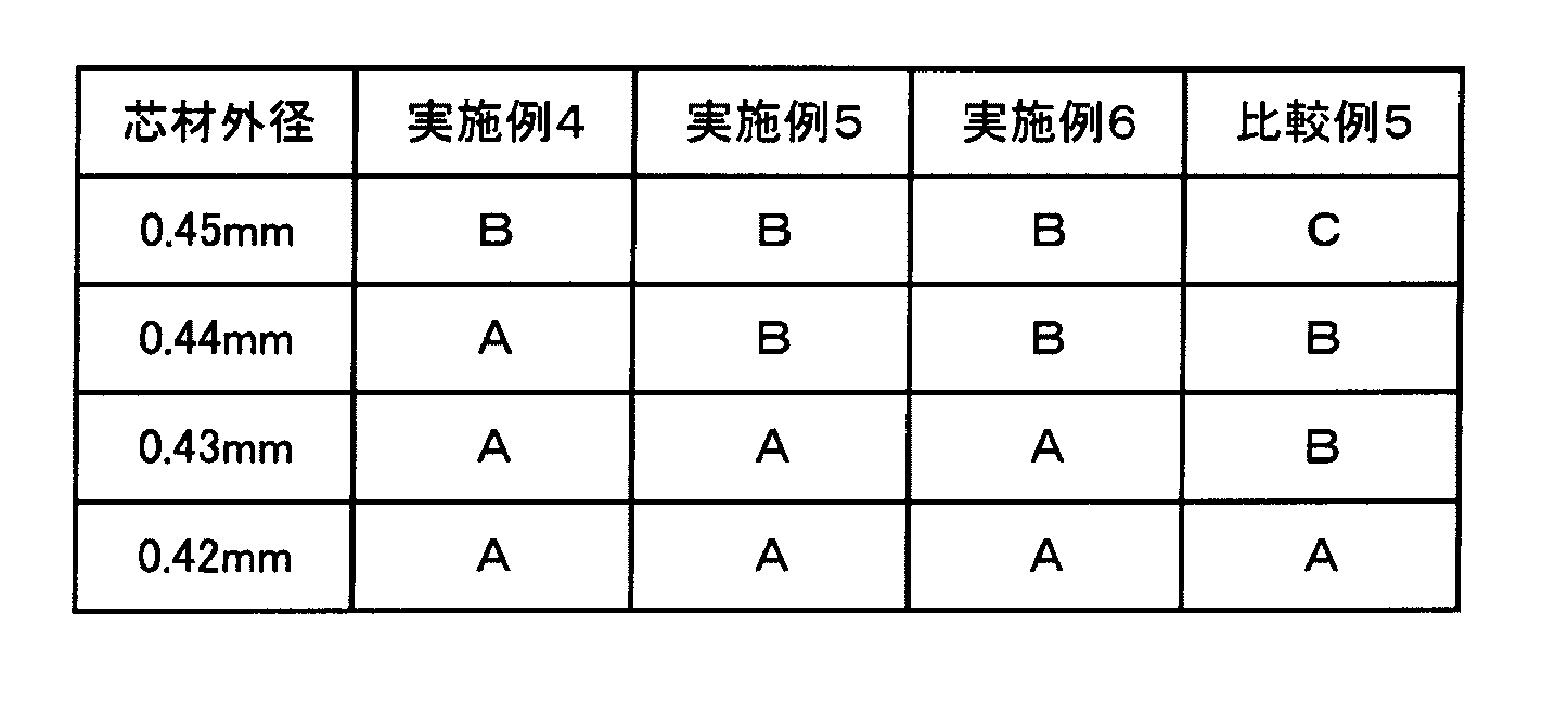
外筒部材の内径(0.45mm)と外径が等しい0.45mmの芯材は、実施例4~実施例6の外筒部材に抵抗はあるが挿入可能であったのに対し、比較例5の外筒部材には抵抗が大きく、挿入が不可能であった。また、外径が0.44mmの芯材は、実施例4の外筒部材に抵抗なく挿入可能であり、かつスライドが可能であった。さらに、外径が0.43mmの芯材は、実施例4~実施例6の外筒部材には抵抗なく挿入およびスライドが可能であるが、比較例5の外筒部材では抵抗があった。
以上のことより、第1層の断面積に対する第2層の断面積の比が小さいものは初期真円率が高く、より大きな外径の部材を抵抗なく挿入および移動が可能である。即ち、第1層の断面積に対する第2層の断面積の比が小さくなるにつれて、摺動性が向上する傾向にある。
1:カテーテル
2:シャフト
3:内挿部材
4:外筒部材
5:第1ルーメン
6:第2ルーメン
7:第3ルーメン
8:バルーン
10:補強部材
20:ハブ
21:流体注入部
22:処置部
31:第1層
32:第2層
33:A層
34:B層
2:シャフト
3:内挿部材
4:外筒部材
5:第1ルーメン
6:第2ルーメン
7:第3ルーメン
8:バルーン
10:補強部材
20:ハブ
21:流体注入部
22:処置部
31:第1層
32:第2層
33:A層
34:B層
Claims (20)
- 遠位側と近位側を有するカテーテルであって、
外筒部材と、 前記外筒部材内に軸方向の少なくとも一部が配置されている内挿部材と、を有するシャフトを有し、
前記外筒部材と前記内挿部材の少なくともいずれか一方が、第1層と、前記第1層と積層されている第2層を有する多層チューブであり、
前記多層チューブの軸方向に直交する断面において、前記第1層の断面積に対する前記第2層の断面積の比(前記第2層の断面積/前記第1層の断面積)が0.7以下であり、
前記第2層を構成する材料は、前記第1層を構成する材料よりも結晶化度が高く、
前記第2層を構成する材料は、前記第1層を構成する材料よりも融点の低い材料を含んでおり、
前記多層チューブの軸方向に直交する断面において、以下の(1)式で計算される初期真円率が92%以上であることを特徴とするカテーテル。
初期真円率(%)=(前記多層チューブの短軸外径/前記多層チューブの長軸外径)×100 (1) - 前記第2層は前記第1層よりも径方向の内側に配置されている、請求項1に記載のカテーテル。
- 前記内挿部材が、前記多層チューブである請求項1または2に記載のカテーテル。
- 前記内挿部材は、ガイドワイヤが挿通される第1ルーメンを有している請求項3に記載のカテーテル。
- 前記シャフトは、前記内挿部材の外側と前記外筒部材の内側の間に流体が供給される第2ルーメンを有している請求項3または4に記載のカテーテル。
- 前記内挿部材は、前記内挿部材の軸方向に直交する断面において、以下の加圧試験後、以下(2)式で計算される加圧試験後真円率が75%以上である請求項5に記載のカテーテル。
(加圧試験)
(i)前記第1ルーメン内に芯材を配置する。
(ii)前記カテーテルを1atm(大気圧)、37℃水中の環境下に置く。
(iii)前記第2ルーメン内に最大拡張圧(RBP)+1atm(大気圧)の圧力を30秒間加える。
(iv)前記第2ルーメン内の圧力を1atm(大気圧)に降圧する。
(v)上記(iii)~(iv)を合計20回繰り返す。
加圧試験後真円率(%)=(初期真円率算出時に前記内挿部材の短軸外径および長軸外径を測定した位置における加圧試験後の前記内挿部材の短軸外径/前記位置における加圧試験後の前記内挿部材の長軸外径)×100 (2) - 前記第2ルーメンに最大拡張圧(RBP)の流体を供給したときの前記内挿部材の最短外径をなす位置での外径減少率が10%以内である請求項5または6に記載のカテーテル。
- 前記内挿部材の最短外径をなす位置が、前記第2ルーメンの内側にある請求項5~7のいずれか一項に記載のカテーテル。
- 前記第2ルーメンが、前記シャフトの遠位側に設けられている請求項5~8のいずれか一項に記載のカテーテル。
- 前記第2ルーメンの遠位側に接続されるバルーンを有する請求項5~9のいずれか一項に記載のカテーテル。
- 前記シャフトは流体が供給される第3ルーメンを有し、
さらに前記カテーテルは、前記シャフトの遠位側に、前記第3ルーメンに接続されるバルーンを有している請求項5~10のいずれか一項に記載のカテーテル。 - 前記第2層を構成する材料のショア硬度に対する、前記第1層を構成する材料のショア硬度の比(第1層を構成する材料のショア硬度/第2層を構成する材料のショア硬度)が0.9以上である請求項1~11のいずれか一項に記載のカテーテル。
- 前記第1層を構成する材料および前記第2層を構成する材料は、熱可塑性樹脂である請求項1~12のいずれか一項に記載のカテーテル。
- 前記第1層を構成する材料は、ポリアミド系樹脂である請求項1~13のいずれか一項に記載のカテーテル。
- 前記第2層を構成する材料は、ポリオレフィン系樹脂である請求項1~14のいずれか一項に記載のカテーテル。
- 前記ポリオレフィン系樹脂が、高密度ポリエチレン樹脂またはポリプロピレン樹脂である請求項15に記載のカテーテル。
- 前記第2層は、A層と該A層と積層されているB層とを有し、
前記B層は、前記第1層と前記A層とを接合している請求項1~16のいずれか一項に記載のカテーテル。 - 前記B層を構成する材料は、直鎖状低密度ポリエチレン樹脂である請求項17に記載のカテーテル。
- 前記外筒部材と前記内挿部材は、遠近方向において相対的に移動可能である請求項1~18のいずれか一項に記載のカテーテル。
- 請求項1~19のいずれか一項に記載のカテーテルを製造する方法であって、
共押出成形により、第1層と前記第1層と積層されている第2層とを有する多層チューブを製造する工程を有する方法。
Priority Applications (5)
| Application Number | Priority Date | Filing Date | Title |
|---|---|---|---|
| US16/957,641 US11684748B2 (en) | 2017-12-27 | 2018-12-13 | Catheter and method for producing same |
| JP2019562967A JPWO2019131158A1 (ja) | 2017-12-27 | 2018-12-13 | カテーテルおよびその製造方法 |
| CN201880083730.9A CN111542364B (zh) | 2017-12-27 | 2018-12-13 | 导管及其制造方法 |
| EP18897817.5A EP3733236A4 (en) | 2017-12-27 | 2018-12-13 | CATHETER AND ITS PRODUCTION PROCESS |
| JP2023015377A JP2023053999A (ja) | 2017-12-27 | 2023-02-03 | カテーテルおよびその製造方法 |
Applications Claiming Priority (2)
| Application Number | Priority Date | Filing Date | Title |
|---|---|---|---|
| JP2017251953 | 2017-12-27 | ||
| JP2017-251953 | 2017-12-27 |
Publications (1)
| Publication Number | Publication Date |
|---|---|
| WO2019131158A1 true WO2019131158A1 (ja) | 2019-07-04 |
Family
ID=67067049
Family Applications (1)
| Application Number | Title | Priority Date | Filing Date |
|---|---|---|---|
| PCT/JP2018/045813 Ceased WO2019131158A1 (ja) | 2017-12-27 | 2018-12-13 | カテーテルおよびその製造方法 |
Country Status (5)
| Country | Link |
|---|---|
| US (1) | US11684748B2 (ja) |
| EP (1) | EP3733236A4 (ja) |
| JP (2) | JPWO2019131158A1 (ja) |
| CN (1) | CN111542364B (ja) |
| WO (1) | WO2019131158A1 (ja) |
Cited By (1)
| Publication number | Priority date | Publication date | Assignee | Title |
|---|---|---|---|---|
| JPWO2023152798A1 (ja) * | 2022-02-08 | 2023-08-17 |
Families Citing this family (3)
| Publication number | Priority date | Publication date | Assignee | Title |
|---|---|---|---|---|
| US20250256072A1 (en) * | 2021-11-09 | 2025-08-14 | Kaneka Corporation | Balloon catheter |
| JPWO2024071115A1 (ja) * | 2022-09-29 | 2024-04-04 | ||
| JPWO2024071117A1 (ja) * | 2022-09-29 | 2024-04-04 |
Citations (5)
| Publication number | Priority date | Publication date | Assignee | Title |
|---|---|---|---|---|
| JPH09505503A (ja) * | 1994-04-13 | 1997-06-03 | シュナイダー・(ユーエスエイ)・インコーポレーテッド | 拡張薬剤搬送カテーテル |
| JPH10305093A (ja) * | 1997-04-25 | 1998-11-17 | Schneider Usa Inc | 3層押し出し医療用チューブ及びそれを組み込んだ医療器具 |
| JP2004033354A (ja) | 2002-07-01 | 2004-02-05 | Terumo Corp | カテーテルおよびその製造方法 |
| JP2007029736A (ja) | 2005-07-27 | 2007-02-08 | Cordis Corp | カテーテルシャフトチューブおよびその作製方法 |
| JP2007236633A (ja) * | 2006-03-08 | 2007-09-20 | Kaneka Corp | カテーテル |
Family Cites Families (22)
| Publication number | Priority date | Publication date | Assignee | Title |
|---|---|---|---|---|
| US6010521A (en) * | 1997-11-25 | 2000-01-04 | Advanced Cardiovasular Systems, Inc. | Catheter member with bondable layer |
| EP1192970B1 (en) * | 1999-05-11 | 2011-07-20 | Kaneka Corporation | Balloon catheter |
| US7807211B2 (en) * | 1999-09-03 | 2010-10-05 | Advanced Cardiovascular Systems, Inc. | Thermal treatment of an implantable medical device |
| JP4841788B2 (ja) * | 2000-02-04 | 2011-12-21 | コンメド エンドスコピック テクノロジーズ インコーポレイテッド | 3管腔結石バルーン・カテーテルおよびその方法 |
| EP1275891B1 (en) * | 2000-04-21 | 2006-01-25 | Kuraray Co., Ltd. | Multilayered tube and medical supply comprising multilayered tube |
| JP3745303B2 (ja) * | 2002-04-11 | 2006-02-15 | 朝日インテック株式会社 | 医療用ガイドワイヤ |
| US7273485B2 (en) * | 2003-03-20 | 2007-09-25 | Advanced Cardiovascular Systems, Inc. | Balloon catheter having a shaft with a variable stiffness inner tubular member |
| US7273487B1 (en) * | 2003-12-18 | 2007-09-25 | Advanced Cardiovascular Systems, Inc. | Balloon catheter having a multilayered shaft with variable flexibility |
| US7601285B2 (en) * | 2003-12-31 | 2009-10-13 | Boston Scientific Scimed, Inc. | Medical device with varying physical properties and method for forming same |
| US7166100B2 (en) | 2004-06-29 | 2007-01-23 | Cordis Neurovascular, Inc. | Balloon catheter shaft design |
| JP5148878B2 (ja) * | 2004-11-26 | 2013-02-20 | 三井化学株式会社 | 医療用チューブ |
| US10029034B2 (en) * | 2005-12-15 | 2018-07-24 | CARDINAL HEALTH SWITZERLAND 515 GmbH | Drug-eluting articles with improved drug release profiles |
| EP2371414A4 (en) * | 2008-12-11 | 2012-07-25 | Kaneka Corp | MEDICAL TUBUS |
| US9011745B2 (en) * | 2010-06-10 | 2015-04-21 | Kaneka Corporation | Method for manufacturing a medical tube |
| JP5829833B2 (ja) * | 2011-04-21 | 2015-12-09 | 株式会社グッドマン | バルーンカテーテル |
| WO2014025142A1 (ko) * | 2012-08-07 | 2014-02-13 | 주식회사 폴리사이언텍 | 폴리염화비닐-프리 의료용 튜브, 성형부품 및 이로부터 제조되는 의료용품 |
| JP2016519589A (ja) * | 2013-03-15 | 2016-07-07 | アボット カーディオバスキュラー システムズ インコーポレイテッド | カテーテルシャフト及び当該カテーテルシャフトを形成する方法 |
| AU2014262488B2 (en) * | 2013-05-10 | 2018-08-30 | Medtronic, Inc. | System for deploying a device to a distal location across a diseased vessel |
| US10065017B2 (en) * | 2014-04-02 | 2018-09-04 | Merit Medical Systems, Inc. | Catheter with catheter tip and related methods |
| JP2016214821A (ja) * | 2015-05-19 | 2016-12-22 | アボット カーディオバスキュラー システムズ インコーポレイテッド | モノリシック構造の多層末端外側部材を有するカテーテル |
| JP6921660B2 (ja) * | 2016-07-06 | 2021-08-18 | 株式会社カネカ | ガイドワイヤサポートカテーテル |
| WO2018212126A1 (ja) * | 2017-05-15 | 2018-11-22 | テルモ株式会社 | バルーンカテーテル、およびバルーンカテーテルの製造方法 |
-
2018
- 2018-12-13 CN CN201880083730.9A patent/CN111542364B/zh active Active
- 2018-12-13 JP JP2019562967A patent/JPWO2019131158A1/ja active Pending
- 2018-12-13 EP EP18897817.5A patent/EP3733236A4/en active Pending
- 2018-12-13 US US16/957,641 patent/US11684748B2/en active Active
- 2018-12-13 WO PCT/JP2018/045813 patent/WO2019131158A1/ja not_active Ceased
-
2023
- 2023-02-03 JP JP2023015377A patent/JP2023053999A/ja active Pending
Patent Citations (5)
| Publication number | Priority date | Publication date | Assignee | Title |
|---|---|---|---|---|
| JPH09505503A (ja) * | 1994-04-13 | 1997-06-03 | シュナイダー・(ユーエスエイ)・インコーポレーテッド | 拡張薬剤搬送カテーテル |
| JPH10305093A (ja) * | 1997-04-25 | 1998-11-17 | Schneider Usa Inc | 3層押し出し医療用チューブ及びそれを組み込んだ医療器具 |
| JP2004033354A (ja) | 2002-07-01 | 2004-02-05 | Terumo Corp | カテーテルおよびその製造方法 |
| JP2007029736A (ja) | 2005-07-27 | 2007-02-08 | Cordis Corp | カテーテルシャフトチューブおよびその作製方法 |
| JP2007236633A (ja) * | 2006-03-08 | 2007-09-20 | Kaneka Corp | カテーテル |
Cited By (3)
| Publication number | Priority date | Publication date | Assignee | Title |
|---|---|---|---|---|
| JPWO2023152798A1 (ja) * | 2022-02-08 | 2023-08-17 | ||
| WO2023152798A1 (ja) * | 2022-02-08 | 2023-08-17 | 朝日インテック株式会社 | バルーンカテーテルおよびバルーンカテーテルの製造方法 |
| JP7842792B2 (ja) | 2022-02-08 | 2026-04-08 | 朝日インテック株式会社 | バルーンカテーテルおよびバルーンカテーテルの製造方法 |
Also Published As
| Publication number | Publication date |
|---|---|
| EP3733236A1 (en) | 2020-11-04 |
| EP3733236A4 (en) | 2021-10-27 |
| JPWO2019131158A1 (ja) | 2020-12-24 |
| CN111542364B (zh) | 2022-07-15 |
| JP2023053999A (ja) | 2023-04-13 |
| CN111542364A (zh) | 2020-08-14 |
| US11684748B2 (en) | 2023-06-27 |
| US20210052850A1 (en) | 2021-02-25 |
Similar Documents
| Publication | Publication Date | Title |
|---|---|---|
| US10709876B2 (en) | Balloon catheter | |
| CN103796707B (zh) | 具有阶梯形切薄的海波管的导管 | |
| CA2553505C (en) | Catheter shaft tubes and methods of making | |
| US7001420B2 (en) | Coil reinforced multilayered inner tubular member for a balloon catheter | |
| JP2023053999A (ja) | カテーテルおよびその製造方法 | |
| CN105188823B (zh) | 用于导管的减少材料的尖端及形成其的方法 | |
| JP2016519589A (ja) | カテーテルシャフト及び当該カテーテルシャフトを形成する方法 | |
| JP5918553B2 (ja) | バルーンカテーテル | |
| JP2010115375A (ja) | 医療用バルーンカテーテル | |
| JP5066992B2 (ja) | バルーンカテーテル | |
| JP5829833B2 (ja) | バルーンカテーテル | |
| JP7159409B2 (ja) | ガイドワイヤサポートカテーテル | |
| JP4914282B2 (ja) | 押圧性を備えたカテーテル | |
| JP2008110132A (ja) | カテーテル | |
| JP4785567B2 (ja) | カテーテル | |
| JP2008264119A (ja) | 押圧性を備えたカテーテル |
Legal Events
| Date | Code | Title | Description |
|---|---|---|---|
| 121 | Ep: the epo has been informed by wipo that ep was designated in this application |
Ref document number: 18897817 Country of ref document: EP Kind code of ref document: A1 |
|
| WWE | Wipo information: entry into national phase |
Ref document number: 2019562967 Country of ref document: JP |
|
| NENP | Non-entry into the national phase |
Ref country code: DE |
|
| ENP | Entry into the national phase |
Ref document number: 2018897817 Country of ref document: EP Effective date: 20200727 |