WO2019131446A1 - ワークの熱処理方法及び熱処理装置 - Google Patents
ワークの熱処理方法及び熱処理装置 Download PDFInfo
- Publication number
- WO2019131446A1 WO2019131446A1 PCT/JP2018/047023 JP2018047023W WO2019131446A1 WO 2019131446 A1 WO2019131446 A1 WO 2019131446A1 JP 2018047023 W JP2018047023 W JP 2018047023W WO 2019131446 A1 WO2019131446 A1 WO 2019131446A1
- Authority
- WO
- WIPO (PCT)
- Prior art keywords
- space
- work
- enclosed space
- measured
- exhaust
- Prior art date
- Legal status (The legal status is an assumption and is not a legal conclusion. Google has not performed a legal analysis and makes no representation as to the accuracy of the status listed.)
- Ceased
Links
Images


Classifications
-
- C—CHEMISTRY; METALLURGY
- C21—METALLURGY OF IRON
- C21D—MODIFYING THE PHYSICAL STRUCTURE OF FERROUS METALS; GENERAL DEVICES FOR HEAT TREATMENT OF FERROUS OR NON-FERROUS METALS OR ALLOYS; MAKING METAL MALLEABLE, e.g. BY DECARBURISATION OR TEMPERING
- C21D9/00—Heat treatment, e.g. annealing, hardening, quenching or tempering, adapted for particular articles; Furnaces therefor
- C21D9/0062—Heat-treating apparatus with a cooling or quenching zone
-
- C—CHEMISTRY; METALLURGY
- C21—METALLURGY OF IRON
- C21D—MODIFYING THE PHYSICAL STRUCTURE OF FERROUS METALS; GENERAL DEVICES FOR HEAT TREATMENT OF FERROUS OR NON-FERROUS METALS OR ALLOYS; MAKING METAL MALLEABLE, e.g. BY DECARBURISATION OR TEMPERING
- C21D1/00—General methods or devices for heat treatment, e.g. annealing, hardening, quenching or tempering
- C21D1/18—Hardening; Quenching with or without subsequent tempering
-
- C—CHEMISTRY; METALLURGY
- C21—METALLURGY OF IRON
- C21D—MODIFYING THE PHYSICAL STRUCTURE OF FERROUS METALS; GENERAL DEVICES FOR HEAT TREATMENT OF FERROUS OR NON-FERROUS METALS OR ALLOYS; MAKING METAL MALLEABLE, e.g. BY DECARBURISATION OR TEMPERING
- C21D1/00—General methods or devices for heat treatment, e.g. annealing, hardening, quenching or tempering
- C21D1/62—Quenching devices
- C21D1/63—Quenching devices for bath quenching
-
- C—CHEMISTRY; METALLURGY
- C21—METALLURGY OF IRON
- C21D—MODIFYING THE PHYSICAL STRUCTURE OF FERROUS METALS; GENERAL DEVICES FOR HEAT TREATMENT OF FERROUS OR NON-FERROUS METALS OR ALLOYS; MAKING METAL MALLEABLE, e.g. BY DECARBURISATION OR TEMPERING
- C21D1/00—General methods or devices for heat treatment, e.g. annealing, hardening, quenching or tempering
- C21D1/74—Methods of treatment in inert gas, controlled atmosphere, vacuum or pulverulent material
- C21D1/76—Adjusting the composition of the atmosphere
-
- C—CHEMISTRY; METALLURGY
- C21—METALLURGY OF IRON
- C21D—MODIFYING THE PHYSICAL STRUCTURE OF FERROUS METALS; GENERAL DEVICES FOR HEAT TREATMENT OF FERROUS OR NON-FERROUS METALS OR ALLOYS; MAKING METAL MALLEABLE, e.g. BY DECARBURISATION OR TEMPERING
- C21D11/00—Process control or regulation for heat treatments
-
- C—CHEMISTRY; METALLURGY
- C21—METALLURGY OF IRON
- C21D—MODIFYING THE PHYSICAL STRUCTURE OF FERROUS METALS; GENERAL DEVICES FOR HEAT TREATMENT OF FERROUS OR NON-FERROUS METALS OR ALLOYS; MAKING METAL MALLEABLE, e.g. BY DECARBURISATION OR TEMPERING
- C21D9/00—Heat treatment, e.g. annealing, hardening, quenching or tempering, adapted for particular articles; Furnaces therefor
- C21D9/0006—Details, accessories not peculiar to any of the following furnaces
- C21D9/0018—Details, accessories not peculiar to any of the following furnaces for charging, discharging or manipulation of charge
-
- C—CHEMISTRY; METALLURGY
- C21—METALLURGY OF IRON
- C21D—MODIFYING THE PHYSICAL STRUCTURE OF FERROUS METALS; GENERAL DEVICES FOR HEAT TREATMENT OF FERROUS OR NON-FERROUS METALS OR ALLOYS; MAKING METAL MALLEABLE, e.g. BY DECARBURISATION OR TEMPERING
- C21D9/00—Heat treatment, e.g. annealing, hardening, quenching or tempering, adapted for particular articles; Furnaces therefor
- C21D9/0006—Details, accessories not peculiar to any of the following furnaces
- C21D9/0025—Supports; Baskets; Containers; Covers
-
- C—CHEMISTRY; METALLURGY
- C21—METALLURGY OF IRON
- C21D—MODIFYING THE PHYSICAL STRUCTURE OF FERROUS METALS; GENERAL DEVICES FOR HEAT TREATMENT OF FERROUS OR NON-FERROUS METALS OR ALLOYS; MAKING METAL MALLEABLE, e.g. BY DECARBURISATION OR TEMPERING
- C21D9/00—Heat treatment, e.g. annealing, hardening, quenching or tempering, adapted for particular articles; Furnaces therefor
- C21D9/005—Furnaces in which the charge is moving up or down
-
- C—CHEMISTRY; METALLURGY
- C21—METALLURGY OF IRON
- C21D—MODIFYING THE PHYSICAL STRUCTURE OF FERROUS METALS; GENERAL DEVICES FOR HEAT TREATMENT OF FERROUS OR NON-FERROUS METALS OR ALLOYS; MAKING METAL MALLEABLE, e.g. BY DECARBURISATION OR TEMPERING
- C21D9/00—Heat treatment, e.g. annealing, hardening, quenching or tempering, adapted for particular articles; Furnaces therefor
- C21D9/40—Heat treatment, e.g. annealing, hardening, quenching or tempering, adapted for particular articles; Furnaces therefor for rings; for bearing races
-
- F—MECHANICAL ENGINEERING; LIGHTING; HEATING; WEAPONS; BLASTING
- F27—FURNACES; KILNS; OVENS; RETORTS
- F27B—FURNACES, KILNS, OVENS OR RETORTS IN GENERAL; OPEN SINTERING OR LIKE APPARATUS
- F27B9/00—Furnaces through which the charge is moved mechanically, e.g. of tunnel type; Similar furnaces in which the charge moves by gravity
- F27B9/06—Furnaces through which the charge is moved mechanically, e.g. of tunnel type; Similar furnaces in which the charge moves by gravity heated without contact between combustion gases and charge; electrically heated
- F27B9/062—Furnaces through which the charge is moved mechanically, e.g. of tunnel type; Similar furnaces in which the charge moves by gravity heated without contact between combustion gases and charge; electrically heated electrically heated
- F27B9/067—Furnaces through which the charge is moved mechanically, e.g. of tunnel type; Similar furnaces in which the charge moves by gravity heated without contact between combustion gases and charge; electrically heated electrically heated heated by induction
-
- F—MECHANICAL ENGINEERING; LIGHTING; HEATING; WEAPONS; BLASTING
- F27—FURNACES; KILNS; OVENS; RETORTS
- F27B—FURNACES, KILNS, OVENS OR RETORTS IN GENERAL; OPEN SINTERING OR LIKE APPARATUS
- F27B9/00—Furnaces through which the charge is moved mechanically, e.g. of tunnel type; Similar furnaces in which the charge moves by gravity
- F27B9/12—Furnaces through which the charge is moved mechanically, e.g. of tunnel type; Similar furnaces in which the charge moves by gravity with special arrangements for preheating or cooling the charge
-
- F—MECHANICAL ENGINEERING; LIGHTING; HEATING; WEAPONS; BLASTING
- F27—FURNACES; KILNS; OVENS; RETORTS
- F27B—FURNACES, KILNS, OVENS OR RETORTS IN GENERAL; OPEN SINTERING OR LIKE APPARATUS
- F27B9/00—Furnaces through which the charge is moved mechanically, e.g. of tunnel type; Similar furnaces in which the charge moves by gravity
- F27B9/14—Furnaces through which the charge is moved mechanically, e.g. of tunnel type; Similar furnaces in which the charge moves by gravity characterised by the path of the charge during treatment; characterised by the means by which the charge is moved during treatment
- F27B9/20—Furnaces through which the charge is moved mechanically, e.g. of tunnel type; Similar furnaces in which the charge moves by gravity characterised by the path of the charge during treatment; characterised by the means by which the charge is moved during treatment the charge moving in a substantially straight path
-
- F—MECHANICAL ENGINEERING; LIGHTING; HEATING; WEAPONS; BLASTING
- F27—FURNACES; KILNS; OVENS; RETORTS
- F27B—FURNACES, KILNS, OVENS OR RETORTS IN GENERAL; OPEN SINTERING OR LIKE APPARATUS
- F27B9/00—Furnaces through which the charge is moved mechanically, e.g. of tunnel type; Similar furnaces in which the charge moves by gravity
- F27B9/30—Details, accessories or equipment specially adapted for furnaces of these types
- F27B9/36—Arrangements of heating devices
-
- H—ELECTRICITY
- H05—ELECTRIC TECHNIQUES NOT OTHERWISE PROVIDED FOR
- H05B—ELECTRIC HEATING; ELECTRIC LIGHT SOURCES NOT OTHERWISE PROVIDED FOR; CIRCUIT ARRANGEMENTS FOR ELECTRIC LIGHT SOURCES, IN GENERAL
- H05B6/00—Heating by electric, magnetic or electromagnetic fields
- H05B6/02—Induction heating
- H05B6/10—Induction heating apparatus, other than furnaces, for specific applications
- H05B6/101—Induction heating apparatus, other than furnaces, for specific applications for local heating of metal pieces
- H05B6/103—Induction heating apparatus, other than furnaces, for specific applications for local heating of metal pieces multiple metal pieces successively being moved close to the inductor
-
- C—CHEMISTRY; METALLURGY
- C21—METALLURGY OF IRON
- C21D—MODIFYING THE PHYSICAL STRUCTURE OF FERROUS METALS; GENERAL DEVICES FOR HEAT TREATMENT OF FERROUS OR NON-FERROUS METALS OR ALLOYS; MAKING METAL MALLEABLE, e.g. BY DECARBURISATION OR TEMPERING
- C21D1/00—General methods or devices for heat treatment, e.g. annealing, hardening, quenching or tempering
- C21D1/34—Methods of heating
- C21D1/42—Induction heating
-
- F—MECHANICAL ENGINEERING; LIGHTING; HEATING; WEAPONS; BLASTING
- F27—FURNACES; KILNS; OVENS; RETORTS
- F27D—DETAILS OR ACCESSORIES OF FURNACES, KILNS, OVENS OR RETORTS, IN SO FAR AS THEY ARE OF KINDS OCCURRING IN MORE THAN ONE KIND OF FURNACE
- F27D3/00—Charging; Discharging; Manipulation of charge
- F27D2003/0034—Means for moving, conveying, transporting the charge in the furnace or in the charging facilities
- F27D2003/0065—Lifts, e.g. containing the bucket elevators
-
- Y—GENERAL TAGGING OF NEW TECHNOLOGICAL DEVELOPMENTS; GENERAL TAGGING OF CROSS-SECTIONAL TECHNOLOGIES SPANNING OVER SEVERAL SECTIONS OF THE IPC; TECHNICAL SUBJECTS COVERED BY FORMER USPC CROSS-REFERENCE ART COLLECTIONS [XRACs] AND DIGESTS
- Y02—TECHNOLOGIES OR APPLICATIONS FOR MITIGATION OR ADAPTATION AGAINST CLIMATE CHANGE
- Y02P—CLIMATE CHANGE MITIGATION TECHNOLOGIES IN THE PRODUCTION OR PROCESSING OF GOODS
- Y02P10/00—Technologies related to metal processing
- Y02P10/25—Process efficiency
Definitions
- the present invention relates to a heat treatment method and a heat treatment apparatus for a workpiece, and more particularly to a technology for performing a predetermined heat treatment by heating the workpiece and then cooling it.
- heat treatment is performed to impart mechanical strength and the like required to the annular member.
- the heat treatment includes a heating process in which a heating process for heating the base material (annular work) of the annular member to a target temperature is performed, and a cooling process in which a cooling process for cooling and quenching the heated work is performed.
- a heating process can be implemented using atmosphere heating furnaces, such as a mesh belt type continuous furnace, or an induction heating device.
- induction heating has the advantage of being able to realize a compact heat treatment apparatus, in addition to being able to achieve high energy efficiency since only work can be heated directly.
- the heat treatment apparatus disclosed in Patent Document 1 and Patent Document 2 cools a heating unit for induction heating a work to a target temperature and a work after heating in a container capable of producing a non-oxidizing atmosphere.
- a cooling unit is provided side by side, and one work (one work) held by an appropriate means is inductively heated to a target temperature by the heating unit, and then the heated work is lowered to the arrangement position of the cooling unit. It is configured to cool and harden the workpiece by injecting the coolant toward the workpiece.
- the heat treatment apparatus having such a configuration can not perform any treatment on the subsequent work until the heat treatment (heating and cooling after heating) on one work is completed. Therefore, the treatment efficiency is low and it is not preferable as a heat treatment apparatus used in the production process of mass-produced parts such as rolling bearings of rolling bearings.
- the heat treatment apparatus and the heat treatment method have a first space for opening and closing a work that can be opened and closed, and a first space for performing a heating process, and an opening for the work with a liquid surface which is connected to the first space to immerse the work. Both heating and cooling are performed in a state where the second space in which the part is closed is a closed space and the closed space is a non-oxidizing atmosphere.
- the atmosphere of the sealed space for the heat treatment and the cooling treatment is replaced with a non-oxidizing atmosphere in a short time and while suppressing the fluctuation of the liquid level of the coolant.
- this heat treatment method includes a heating step of heating the work and a cooling step of cooling the work and performing a predetermined heat treatment by immersing the work heated in the heating step in the cooling liquid, An inlet side opening of the work is provided in the first space to be carried out, an outlet side opening of the work is provided in a second space connected to the first space and in contact with the liquid surface of the coolant, and the inlet side opening is closed and Work that performs the heating process and the cooling process in a state in which the first space and the second space are sealed together by closing the outlet side opening with the liquid surface of the cooling liquid and the sealed space is in a non-oxidizing atmosphere
- the heat treatment method further comprising a preparatory step of setting the atmosphere of the enclosed space to a non-oxidizing atmosphere and bringing the work into the enclosed space before the heating step, and With the supply of oxidizing gas It performs together with the exhaust of the closed space, characterized with a
- non-oxidizing atmosphere refers not only to an atmosphere in which no oxygen is present, but also to an atmosphere in which a slight amount of oxygen is present to the extent that oxide scale is not generated on the surface of a workpiece Is a concept that includes Similarly, the term “non-oxidizing gas” as used herein refers not only to a gas that does not contain any oxygen, but also to a gas that contains a small amount of oxygen to the extent that oxide scale is not generated on the surface of a workpiece (for example, an oxygen concentration of 100 ppm The following concept is included. The same applies to a heat treatment apparatus according to the present invention described later.
- the atmosphere in the enclosed space is made non-oxidative, and in the preparatory step of bringing the work into the enclosed space ready state, the non-oxidized space is not oxidized.
- the supply of hydrogen gas and the evacuation of the enclosed space are performed together.
- the rate of substitution with a non-oxidizing atmosphere can be increased as compared to the case where only a non-oxidizing gas is supplied or the case where only a closed space is exhausted. Therefore, the operation of the heat treatment apparatus can be quickly started, and the productivity can be improved.
- the supply of the non-oxidizing gas and the exhaust of the enclosed space are controlled according to the pressure of the enclosed space, so even if the amount of air supplied or the amount of exhaust is increased
- the pressure of the space can be maintained within a preset range. Therefore, it is possible to quickly replace the atmosphere of the enclosed space with a non-oxidizing atmosphere while stabilizing the liquid level of the coolant.
- the work subjected to the heat treatment in the closed space is cooled in the coolant adjacent to the closed space and subjected to a predetermined heat treatment. Therefore, when one work is cooled after finishing the heating process (when immersed in the coolant), the next work can be subjected to heat treatment in a closed space, or the work after the heat treatment is a coolant It can be transported to the second space in contact with the liquid surface of the Thereby, the heat treatment and the cooling treatment for a plurality of workpieces can be simultaneously progressed in a non-oxidizing atmosphere. Therefore, heat treatment can be efficiently performed on a plurality of workpieces without generating oxide scale on the surface of the workpieces, and it becomes possible to cope with the production of mass-produced parts.
- the pressure of the sealed space is measured, and when the measured pressure is equal to or higher than the upper pressure threshold, the supply of non-oxidizing gas to the sealed space is stopped and sealed. Control may be performed to continue exhaust of the space.
- the air pressure in the enclosed space is measured, and if the measured air pressure is less than the lower threshold pressure, supply of non-oxidizing gas to the enclosed space is continued and sealed. Control may be performed to stop the exhaust of space.
- the exhaust of the enclosed space is stopped to reduce the pressure associated with the exhaust. It can be suppressed.
- the oxygen concentration can be reduced and the air pressure can be increased by continuing the supply of the non-oxidizing gas to the sealed space. Therefore, it is possible to bring the closed space closer to an atmosphere (non-oxidizing atmosphere) of an oxygen concentration targeted for the closed space, while returning the air pressure to the allowable range.
- the air pressure in the enclosed space is measured, and when the measured air pressure is larger than the lower atmospheric pressure threshold and lower than the upper atmospheric pressure threshold, the oxygen concentration in the enclosed space is measured. If the measured oxygen concentration is equal to or higher than the oxygen concentration threshold value, control may be performed to continue the supply of the non-oxidizing gas to the enclosed space and to continue the exhaust of the enclosed space.
- the supply of the non-oxidizing gas and the exhaust of the sealed space are continued to effectively keep the pressure stable.
- the oxygen concentration in the enclosed space can be reduced.
- the oxygen concentration in the enclosed space is effectively reduced while the pressure is stabilized, the oxygen concentration is measured, and it is determined whether the measured oxygen concentration has reached the target value or less. Then, when it is determined that the pressure has not reached the target value or less yet, the air supply and exhaust is continued while performing the above-described atmospheric pressure control.
- the sealed space can be reliably replaced with a non-oxidizing atmosphere.
- the air pressure in the enclosed space is measured, and when the measured air pressure is larger than the lower atmospheric pressure threshold and lower than the upper atmospheric pressure threshold, the oxygen concentration in the enclosed space is measured. If the measured oxygen concentration is less than the oxygen concentration threshold, control may be performed to stop the supply of non-oxidative gas to the enclosed space and to stop the exhaust of the enclosed space.
- the pressure in the enclosed space is measured at regular intervals, and when the measured pressure is larger than the lower pressure threshold and lower than the upper pressure threshold, oxygen in the enclosed space is measured.
- the concentration may be measured, and the supply of the non-oxidizing gas according to the measured atmospheric pressure and the control of the exhaust of the enclosed space may be repeated until the measured oxygen concentration falls below the oxygen concentration threshold.
- the pressure and oxygen concentration are measured at regular intervals, and the control of air supply and exhaust according to the measured pressure is repeated until each numerical value falls within the predetermined range, thereby accurately controlling the pressure in the enclosed space.
- the oxygen concentration can be rapidly reduced.
- the work is carried into the replacement chamber adjacent to the first space through the entrance side opening with the entrance side opening closed, and the atmosphere of the enclosed space is not
- the inlet side opening may be opened to carry the work into the sealed space.
- the work may be induction-heated to a target temperature in the heating step, and the work heated in the cooling step may be cooled and quenched.
- the heat treatment method of the work according to the above description can improve the productivity of the work by shortening the time required for the operation of the heat treatment apparatus, it is possible to use, for example, a bearing ring of a rolling bearing. It is suitable as a method for subjecting mass-produced parts to heat treatment.
- this heat treatment apparatus includes a heating unit for heating the work, and a cooling unit for cooling the work and performing a predetermined heat treatment by immersing the work heated by the heating unit in the cooling liquid, the heating unit , and the cooling unit has a second space connected to the first space and in contact with the liquid surface of the cooling liquid, and the inlet side opening of the work is provided in the first space The outlet side opening of the work is provided in the second space, the inlet side opening is closed, and the outlet side opening is closed by the liquid surface of the coolant, thereby the first space and the second space are both sealed.
- exhaust system that performs Besides supplying non-oxidative gas between the two and exhausting the enclosed space by the exhaust device together, it further comprises a control unit that controls these supply and exhaust according to the air pressure measured by the air pressure measuring device. Will be attached.
- the substituted speed to non-oxidizing atmosphere can be improved similarly to the heat processing method which concerns on this invention mentioned above. Therefore, the operation of the heat treatment apparatus can be quickly started, and the productivity can be improved. Further, since the supply of non-oxidizing gas and the exhaust of the enclosed space can be controlled according to the pressure of the enclosed space, the pressure of the enclosed space is maintained within a preset range even if the air supply amount and the exhaust amount are increased. be able to. Therefore, it is possible to quickly replace the atmosphere of the enclosed space with a non-oxidizing atmosphere while stabilizing the liquid level of the coolant.
- the atmosphere of the enclosed space for the heat treatment and the cooling treatment in a short time while suppressing the fluctuation of the liquid level of the coolant. Can be replaced with a non-oxidizing atmosphere, so that the time required for the operation of the heat treatment apparatus can be shortened, and the productivity of the work related to the heat treatment can be improved.
- FIG. 1 It is a perspective view of the heat treatment apparatus concerning one embodiment of the present invention. It is a front view of the heat processing apparatus shown in FIG. It is sectional drawing of a heating part. It is a perspective view of a heating device. It is a sectional view of a cooling unit. It is a block diagram showing composition of an air supply and exhaust control system of heat treatment equipment. It is a flow chart which shows the flow of the whole heat treatment method concerning one embodiment of the present invention. It is a flowchart which shows the flow of a preparatory process among the heat processing methods which concern on one Embodiment of this invention. It is a flowchart which shows an example of the air supply / exhaust control in a preparatory process.
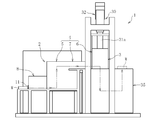
- FIG. 1 is a perspective view showing the entire structure of a heat treatment apparatus according to an embodiment of the present invention
- FIG. 2 is a front view of the heat treatment apparatus.
- the heat treatment apparatus 1 shown in FIGS. 1 and 2 is an annular work W (in this embodiment, a base material of an outer ring of a rolling bearing) made of steel such as SUJ 2 along a path shown by a two-dot chain line in FIG.
- This is a so-called continuous heat treatment apparatus 1 configured to subject the work W to quench hardening while being fed.
- the heat treatment apparatus 1 includes the heating unit 2 in which the heating step S2 (see FIG.
- the cooling unit 3 includes a cooling step S3 (see FIG. 7A described later) for cooling and quenching the work W heated by the heating unit 2.
- the heat treatment apparatus 1 is configured such that the heating step S2 and the cooling step S3 can be performed in a non-oxidizing atmosphere.
- the heat treatment apparatus 1 further includes an air supply and discharge control system 40 for the enclosed space D which is an internal space of the enclosed chamber 4.
- the heating unit 2 includes a heating device 20, a heating chamber 5, a replacement chamber 8, and a passage chamber 7.
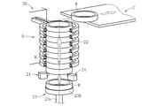
- the heating device 20 is for induction heating the work W to a target temperature, and in the present embodiment, as shown in FIG. 3 and FIG. 4, a support capable of supporting a plurality of works W in a stacked state
- the member 21, the heating coil 22 disposed radially outward of the work W supported by the support member 21, and the lower side of the support member 21, the workpiece W is conveyed to the support member 21 (conveyed from the upstream side of the path And work supply means 23 for supplying the subsequent work W).
- the support members 21 are disposed at a plurality of places (for example, three places) separated in the circumferential direction of the work W to be supported.
- Each support member 21 is provided so as to be movable back and forth along the radial direction of the work W to be supported, and as the work W is supplied from the lower side by the work supply means 23, the work W to be supported After moving radially outward to receive the work W and receiving the work W, the work W is moved radially inward to be supported to support the work W from below.
- the heating coil 22 is, for example, a so-called multi-turn coil in which a tubular body made of a conductive metal such as a copper tube is spirally wound, and is arranged coaxially with the work W supported by the support member 21.
- a heating coil 22 one having a total length (axial direction) dimension several times to several tens times the axial dimension of the workpiece W is used.
- the heating coil 22 having such a full length dimension as the plurality of works W supported in a stacked state by the support member 21 are fed upward in the inner region of the heating coil 22 in the energized state.
- each work W is induction heated sequentially to the target temperature.
- the work supply means 23 is constituted by, for example, a power cylinder (hydraulic cylinder, air cylinder, or electric cylinder) having a telescopic cylinder rod 23a coaxially arranged with the work W supported by the support member 21. At the tip of the cylinder rod 23a, a flange portion 23b capable of mounting the work W is provided.
- a power cylinder hydraulic cylinder, air cylinder, or electric cylinder
- the heating device 20 having the above configuration is disposed in the internal space of the heating chamber 5 as the first space A in the present invention, and is substituted on the upstream side (rear side in the work W feeding direction) of the heating chamber 5.
- the chamber 8 is disposed on the downstream side of the heating chamber 5 (the forward side in the feeding direction of the work W), and the passage chamber 7 is disposed adjacent to the heating chamber 5.
- the heating chamber 5 cooperates with the passage chamber 7 and the quenching preparation chamber 6 described later to make the indoor atmosphere (the indoor atmosphere during operation of the heat treatment apparatus 1) non-oxidizing atmosphere. It forms a closed chamber 4 to be maintained.
- the heating chamber 5, the passage chamber 7, and the quenching preparation chamber 6 are arranged in order along the feed direction of the work W, and as shown in FIGS. 3 and 5, heating as the first space A
- the internal space of the chamber 5 and the internal space of the quenching preparation chamber 6 as the second space B in the present invention are connected via the internal space (passage C) of the passage chamber 7 provided between the two chambers 5 and 6 ing.
- the closed chamber 4 includes the first space A, the second space B, and the passage C provided separately from each other, and the first space A and the second space B, And the passage C constitute a closed space D in the present invention.
- the sealed chamber 4 further includes an inlet-side opening 4a (see FIG. 3) for introducing the work W into the internal space of the heating chamber 5, and an outlet-side opening 4b provided on the bottom wall of the hardening preparation chamber 6. (See FIG. 5).
- the inlet side opening 4a is opened or closed by the opening and closing means (second opening and closing means 12) shown in FIG. 3, and the outlet side opening 4b is stored in the cooling liquid storage tank 35 as shown in FIG. It is always closed by the surface of the coolant 36.
- the air supply / exhaust control system 40 according to the internal space (closed space D) of the closed chamber 4 will be described later.
- the substitution chamber 8 is installed for the purpose of maintaining the indoor atmosphere (the atmosphere of the enclosed space D) of the closed chamber 4 including the heating chamber 5 in a non-oxidative atmosphere when the work W is introduced into the internal space of the heating chamber 5 There is. Therefore, although illustration is omitted, in order to enable substitution of the atmosphere in substitution chamber 8 with non-oxidizing atmosphere in substitution chamber 8, air supply for supplying non-oxidizing gas into substitution chamber 8 A device, an exhaust device for exhausting the inside of the replacement chamber 8, an air supply pipe connecting the air supply device and the inside of the replacement chamber 8, and an exhaust pipe connecting the exhaust device and the inside of the replacement chamber 8 are provided.
- the replacement chamber 8 is provided with an opening 8a for introducing the work W into its internal space, and this opening 8a is opened and closed by the opening and closing means (the first opening and closing means 11). Opening or closing is possible.
- Arbitrary opening-and-closing apparatus can be employ
- An opening / closing means (second opening / closing means 12) is provided between the replacement chamber 8 and the heating chamber 5, and the inlet side opening 4a of the enclosed room 4 (the enclosed space D) is provided by the second opening / closing means 12.
- the opening 8a is switched from the closed state to the open state by the first opening / closing means 11, the second opening / closing means 12 closes the inlet side opening 4a of the closed chamber 4 (heating chamber 5) It has become.
- arbitrary opening-and-closing apparatus can be employ
- the heating unit 2 has a transfer means for transferring the work W introduced into the internal space of the replacement chamber 8 to the internal space of the heating chamber 5, although not shown.
- a transfer means for example, a conveyer disposed so as to straddle the bottom of the substitution chamber 8 and the heating chamber 5 or a power cylinder (hydraulic cylinder, air cylinder, electric cylinder) or the like can be employed.
- the internal space of the passage chamber 7 is heated to the target temperature by the heating device 20, and the work W after completion of heating discharged to the outside of the heating device 20 (upper side of the heating coil 22) is hardened as the second space B. It is used as a passage C for transferring toward the inner space of the preparation room 6.
- the passage chamber 7 is provided with transfer means such as a transfer conveyor (not shown), and the work W discharged to the outside of the heating device 20 by this transfer means can be transferred from the first space A to the second space B. .
- the cooling unit 3 is an area where the cooling process of cooling and quenching the work W heated to the target temperature by the heating unit 2 is performed, and the cooling unit 3 of the present embodiment is the work W
- the workpiece W can be cooled (quenched) in a state in which the outer peripheral surface is restrained by the constraining die 33.
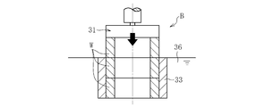
- the cooling unit 3 includes a hardening preparation chamber 6 disposed adjacent to the downstream side of the heating chamber 5 via the passage chamber 7, and a pressing device 30.
- a restraint mold 33, an elevating table 34, and a coolant storage tank 35 are provided.
- the pressing device 30 pressurizes the work W transferred to the internal space (second space B) of the hardening preparation chamber 6 via the internal space (passage C) of the passage chamber 7 downward, and the work W as a coolant
- the pressure member 31 to be immersed in the coolant 36 stored in the storage tank 35, and the lifting unit 32 holding the pressing member 31 so as to be able to move up and down.
- a restraint die 33 is attached and fixed to the lower end of the pressure member 31, and the restraint die 33 can be raised and lowered integrally with the pressure member 31.
- the lifting unit 32 is disposed outside the hardening preparation chamber 6, and as shown in FIG.
- a pressing member 31 and a constraining die 33 attached and fixed to the pressing member 31. Furthermore, only a part of the shaft member holding the pressure member 31 at the lower end is disposed in the second space B.
- the shaft member holding the pressure member 31 is inserted into the through hole penetrating the ceiling wall of the hardening preparation chamber 6 and the through hole (a gap between the inner wall surface of the through hole and the outer diameter surface of the shaft member ) Is sealed with a sealing material (not shown).
- the coolant storage tank 35 is installed on the lower side of the quenching preparation chamber 6 and stores a coolant 36 for cooling and quenching the work W.
- a coolant 36 for cooling and quenching the work W.
- the cooling fluid 36 a known quenching oil, a water-soluble quenching fluid or the like can be used.
- the upper portion of the coolant storage tank 35 is open, and this opening is divided into a first opening 35a and a second opening 35b by the wall of the closed chamber 4 (hardening preparation chamber 6). It is done.
- the outlet side opening 4b of the closed chamber 4 (closed space D) provided in the quenching preparation chamber 6 is a coolant existing in the first opening 35a of the coolant 36 stored in the coolant storage tank 35. It is closed by 36 fluid levels.
- the elevating table 34 is disposed immediately below the pressure member 31 and ascends and descends in the coolant 36.
- the upper end surface 34a of the lifting table 34 is a mounting surface on which the work W is placed, and when the lifting table 34 is positioned at the rising limit, the coolant whose upper end surface 34a is stored in the coolant storage tank 35 The work W transferred from the internal space of the passage chamber 7 is received above the liquid level of 36.
- a delivery means for delivering the quenched work W released from the restraint mold 33 from the lifting table 34 is dispensed.
- a discharge means 37 for receiving the work W and discharging the work W to the outside of the coolant storage tank 35 (heat treatment apparatus 1) is provided.
- the discharging means 37 for example, a lifting table provided separately from the lifting table 34 described above can be employed.
- the lift table for discharging the work is provided so as to be able to move up and down at a position directly below the second opening 35b in the coolant storage tank 35, and the hardened work W is drawn from the second opening 35b to the coolant storage tank 35. Out of the heat treatment apparatus 1.
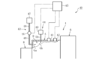
- the air supply and exhaust control system 40 includes an oxygen concentration measuring device 41 for measuring the oxygen concentration in the closed space D which is an internal space of the closed chamber 4 and a pressure measuring device for measuring the air pressure in the closed space D. 42, an air supply device 43 for supplying non-oxidizing gas Ga to the enclosed space D, an exhaust device 44 for exhausting the enclosed space D, and a control unit 45 for controlling the operation of the air supply device 43 and the exhaust device 44. Equipped with
- the oximeter 41 is, for example, an oximeter, and is attached to the closed chamber 4 so that the oxygen concentration in the enclosed space D can be measured.
- the air pressure measuring device 42 is, for example, a pressure sensor, and is attached to the closed chamber 4 so that the oxygen concentration in the closed space D can be measured.
- the air supply device 43 has an air supply valve 46 and a reserve tank 47 in which non-oxidizing gas Ga is stored, and the sealed space D, the air supply valve 46, the air supply valve 46 and the reserve tank 47 are connected by the air supply pipe 48, respectively.
- the exhaust device 44 has an exhaust pump 49, and the sealed space D and the exhaust pump 49 are connected by an exhaust pipe 50.
- the non-oxidizing gas Ga at a pressure higher than the atmospheric pressure (for example, the atmospheric pressure + 0.01 MPa or more) is stored in the reserve tank 47, and the air supply valve 46 is opened.
- the non-oxidizing gas Ga flows into the low enclosed space D automatically. Further, by driving the exhaust pump 49, the gas Gb filling the sealed space D is exhausted to the outside of the heat treatment apparatus 1 through the exhaust pipe 50 (and further passing through the exhaust pump 49).
- any kind of gas can be used as the non-oxidizing gas, for example, an inert gas such as nitrogen gas, helium gas, argon gas, hydrogen gas, carbon monoxide gas, nitrogen dioxide gas, hydrogen sulfide Gases, reducing gases such as sulfur dioxide gas can be used.
- the oxygen concentration measuring device 41, the air pressure measuring device 42, the air supply device 43 (air supply valve 46), and the exhaust device 44 (exhaust pump 49) are all shown in FIG. It is electrically connected. Thereby, the measured value of the oxygen concentration measured by the oxygen concentration measuring device 41 is sent to the control unit 45, and the measured value of the atmospheric pressure measured by the air pressure measuring device 42 is sent to the control unit 45. Further, by the command from the control unit 45 being sent to the air supply valve 46 and the exhaust pump 49, the drive of the air supply valve 46 and the exhaust pump 49 can be controlled based on the command.
- the control unit 45 stores a predetermined control program in advance.
- two control programs are mainly stored.
- the first control program is a program implemented in the preparation step S1 (see FIG. 7A) before the heating step S2
- the second control program is the heating step S2 and the cooling step after the preparation step S1. It is a program implemented in S3.
- the first control program supplies the non-oxidizing gas Ga to the enclosed space D and exhausts the enclosed space D in preparation step S1 (see FIG. 7A) described later. It is set to control these supply and exhaust according to the pressure of the enclosed space D while performing simultaneously.
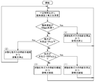
- the air pressure in the enclosed space D is measured at regular intervals, and control of three patterns is performed according to the measured air pressure value. That is, (1) when the measured atmospheric pressure is equal to or higher than the upper atmospheric pressure threshold (in this embodiment, atmospheric pressure + 100 Pa), the supply of the nonoxidizing gas Ga to the enclosed space D is stopped, and the exhaust of the enclosed space D is stopped.
- the air supply device 43 and the exhaust device 44 are controlled to continue.
- the measured atmospheric pressure is equal to or lower than the lower atmospheric pressure threshold (in the present embodiment, atmospheric pressure + 1 Pa)
- the lower atmospheric pressure threshold in the present embodiment, atmospheric pressure + 1 Pa
- the oxygen concentration in the enclosed space is also measured.
- the atmospheric pressure upper limit threshold and the atmospheric pressure lower limit threshold are set to atmospheric pressure + 100 Pa and atmospheric pressure + 1 Pa, respectively, but it is of course not limited thereto. Depending, you may change suitably.
- the threshold value of oxygen concentration is set to 100 ppm in this embodiment, but if it is necessary to control the oxygen concentration of the enclosed space D more strictly depending on the type of the work W or heat treatment, set to 50 ppm. It may be set preferably to 20 ppm, more preferably to 10 ppm or less. The same applies to the threshold value of oxygen concentration in the second control program described later.
- the second control program measures the oxygen concentration and pressure in the enclosed space D at regular intervals in the heating step S2 and the cooling step S3 (see FIG. 7A), and based on the measured values of oxygen concentration and pressure.
- the supply of non-oxidizing gas Ga into the enclosed space D is controlled, and the exhaust of the enclosed space D is controlled.
- the preset oxygen concentration threshold 100 ppm in the present embodiment
- Perform three patterns of control That is, (1) when the measured atmospheric pressure is equal to or higher than the atmospheric pressure upper limit threshold (in this embodiment, the atmospheric pressure + 100 Pa) or more, the supply of the nonoxidizing gas Ga to the enclosed space D is stopped.
- the air supply device 43 and the exhaust device 44 are controlled to continue the exhaust of the enclosed space D.
- the air supply device 43 and the exhaust device 44 are controlled to stop the exhaust of the enclosed space D.
- the air supply device 43 and the exhaust device 44 are controlled to continue the exhaust of the enclosed space D together.
- the supply of non-oxidizing gas Ga to the enclosed space D is stopped, and the exhaust of the enclosed space D is stopped to stop the exhaust of the enclosed space D.
- the device 44 is controlled.
- the heat treatment method of the workpiece W includes a preparation step S1, a heating step S2, and a cooling step S3, as shown in FIG. 7A.
- the preparation step S1 includes a first replacement step S11 for replacing the atmosphere of the enclosed space D with a non-oxidizing atmosphere, and a second replacement step for replacing the atmosphere in the replacement chamber 8 with a non-oxidizing atmosphere.
- the tank 47) is operated to supply the non-oxidizing gas Ga to the enclosed space D, and the exhaust device 44 (exhaust pump 49) is activated to operate the gas present in the enclosed space D (usually at the start of operation). It is done by discharging the atmosphere) Gb. Further, the air supply and discharge by the air supply device 43 and the exhaust device 44 is performed based on a first control program of the control unit 45.
- a first control program of the control unit 45 an example of the flow of control will be described mainly based on FIG.
- the inlet side opening 4a and the outlet side opening 4b of the sealed chamber 4 are closed by a command from the control unit 45, and the air supply device 43 and the exhaust device 44 are operated.
- the non-oxidizing gas Ga is supplied to the chamber and the enclosed space D is exhausted.
- the non-oxidizing gas Ga stored in the reserve tank 47 is supplied to the sealed space D through the air supply pipe 48 by opening the air supply valve 46.
- the gas Gb present in the enclosed space D is discharged to the outside of the enclosed space D (outside of the enclosed chamber 4) through the exhaust pipe 50 by the drive of the exhaust pump 49. Thereby, the process of reducing the oxygen concentration in the enclosed space D is started.
- the air pressure of the enclosed space D is automatically measured by the air pressure measuring device 42 at regular intervals (see FIG. 8).
- the control unit 45 stops the supply of the non-oxidizing gas Ga to the enclosed space D and the enclosed space
- Control commands are sent to the air supply device 43 and the exhaust device 44 so as to continue the exhaust of D.
- commands are supplied to the air supply valve 46 and the exhaust pump 49 so as to close the air supply valve 46 and continue the drive of the exhaust pump 49.
- the control unit 45 continues the supply of the non-oxidizing gas Ga to the enclosed space D and exhausts the enclosed space D Control commands are sent to the air supply device 43 and the exhaust device 44 so as to stop the
- the air supply valve 46 is kept open and a command is sent to the air supply valve 46 and the exhaust pump 49 so as to stop the driving of the exhaust pump 49.
- the control unit 45 measures the oxygen concentration to measure the oxygen concentration in the enclosed space D
- the command is sent to the measuring instrument 41.
- the preset oxygen concentration threshold for example, 100 ppm
- the supply of the non-oxidizing gas Ga to the enclosed space D is continued, and the enclosed space Control commands are sent to the air supply device 43 and the exhaust device 44 so as to continue the exhaust of D.
- the air supply valve 46 is kept open, and a command is sent to the air supply valve 46 and the exhaust pump 49 so as to continue the drive of the exhaust pump 49.
- the reduction of the oxygen concentration in the enclosed space D proceeds toward the target range (less than 100 ppm) in a state where the pressure of the enclosed space D is stabilized within the predetermined range.
- the control unit 45 sends control commands to the air supply device 43 and the exhaust device 44 so as to stop the supply of the non-oxidizing gas Ga to the enclosed space D and to stop the exhaust of the enclosed space D.
- the air supply valve 46 is closed, and the drive of the exhaust pump 49 is stopped.
- the pressure of the enclosed space D is in a predetermined range (more than atmospheric pressure + 1 Pa and less than atmospheric pressure + 100 Pa in this embodiment), and the oxygen concentration is less than 100 ppm, that is, a non-oxidative atmosphere.
- the work W can be carried into the sealed space D while keeping the sealed space D in a non-oxidative atmosphere.
- the work W is carried into the replacement chamber 8 to replace the atmosphere in the replacement chamber 8 with a non-oxidative atmosphere.
- the present invention is not limited thereto.
- the first replacement step S12 and the second replacement step S12 are performed in a state where the work W is carried into the replacement chamber 8 in a state where the inlet side opening 4a is closed in advance. After that, the inlet opening 4a may be opened and the work W may be carried into the sealed space D.
- the first replacement step S11 is performed after the second replacement step S12 is performed in a state where the work W is carried into the replacement chamber 8, the first replacement step S11 is performed. You may implement.
- the subsequent work W is sequentially supported by the support member 21 as it is supplied between the support member 21 and the work W supported by the support member 21 through the above-described procedure.
- An upward feed force is applied to all the workpieces W.
- the work W is induction-heated to the target temperature while being sent upward with the inner region of the heating coil 22 in the energized state, and discharged to the upper side of the heating coil 22 (see FIGS. 3 and 4). reference).
- the work W after completion of heating discharged to the upper region of the heating coil 22 is discharged to the inner space of the passage chamber 7 by an appropriate means not shown, and then the unshown work provided in the inner space of the passage chamber 7
- the medium is sent toward the inner space (i.e., the second space B) of the hardening preparation chamber 6 by the conveyance means of (1) (see FIGS. 3 and 4).
- (S3) Cooling Step In this step, as described above, the cooling process of cooling and quenching the work W heated to the target temperature in the heating unit 2 (heating step) is performed. Specifically, as shown in FIG. 5, first, the workpiece W transferred in the internal space of the passage chamber 7 is received on the upper end surface 34 a of the elevating table 34. Next, the lifting unit 32 (see FIG. 2) of the pressing device 30 is driven to integrally lower the pressing member 31 and the restraint mold 33 attached and fixed to the lower end of the pressing member 31. By disposing the constraining die 33 on the outer periphery of the work W placed on the upper end surface 34 a, the restraint die 33 is brought into a state immediately before the restraint of the outer peripheral surface of the workpiece W is started.
- the fitting of the outer peripheral surface of the work W and the inner peripheral surface of the constraining die 33 is a gap fitting (refer to JIS B 0401-1), and the lower end face of the constraining die 33 and the upper end face of the lifting table 34 It is in contact with 34a.
- the pressing member 31, the restraint mold 33, the work W, and the lifting table 34 are integrally lowered and immersed in the coolant 36 stored in the coolant storage tank 35.
- the workpiece W immersed in the coolant 36 exhibits a deformation behavior such as a diameter reduction deformation after being slightly shrunk, so that the workpiece W has the outer circumferential surface of the workpiece W restrained by the inner circumferential surface of the constraining mold 33 It is cooled as it is.
- the workpiece W is quenched by being rapidly cooled by a predetermined temperature gradient.
- the lifting table 34 When the lifting table 34 reaches the lowering limit, the work W is released from the constraining mold 33.
- the constraining die 33 from which the work W is released moves upward together with the pressure member 31 and returns to the origin.
- the work W released from the restraint mold 33 is dispelled to the outside of the lifting and lowering table 34 by a discharge means (not shown) provided inside the cooling liquid storage tank 35 as shown by a white arrow in FIG. It is taken out and received by the discharge means 37 (work discharge lifting table), and then the liquid surface of the cooling liquid 36 contacts the atmosphere in the upper opening of the cooling liquid storage tank 35 by raising the discharge means 37
- the coolant is discharged from the second opening 35 b to the upper side of the coolant storage tank 35 (outside of the heat treatment apparatus 1).
- the hardening and hardening process on the workpiece W is completed.
- a similar hardening process is applied to the subsequent work W, and the work is discharged to the outside of the heat treatment apparatus 1.
- the hardening and hardening process is performed on the plurality of works W continuously and automatically.
- the closed space D is controlled to a predetermined oxygen concentration range by the second control program of the control unit 45 Be done.
- the flow of control will be mainly described with reference to FIG.
- the oxygen concentration measuring device 41 and the pressure measuring device 42 measure the oxygen concentration and the pressure in the enclosed space D at regular intervals.
- the non-oxidizing gas Ga is not supplied into the sealed space D by the air supply device 43, and the exhaust of the sealed space D by the exhaust device 44 is not performed.
- control unit 45 Control instructions are sent to the air supply device 43 and the exhaust device 44 so as to continue the exhaust of the enclosed space D while stopping the supply of the non-oxidizing gas Ga.
- commands are supplied to the air supply valve 46 and the exhaust pump 49 so as to close the air supply valve 46 and continue the drive of the exhaust pump 49.
- the control unit 45 While continuing the supply of the non-oxidizing gas Ga, control commands are sent to the air supply device 43 and the exhaust device 44 so as to stop the exhaust of the enclosed space D.
- the air supply valve 46 is kept open and a command is sent to the air supply valve 46 and the exhaust pump 49 so as to stop the driving of the exhaust pump 49.
- the measured oxygen concentration is equal to or higher than the oxygen concentration threshold (100 ppm), and (3) the measured atmospheric pressure is larger than the atmospheric pressure lower threshold (atmospheric pressure + 1 Pa) and lower than the atmospheric pressure upper threshold (atmospheric pressure + 100 Pa)
- the control unit 45 sends a control command to the air supply device 43 and the exhaust device 44 so as to continue the supply of the non-oxidizing gas Ga to the enclosed space D and the exhaust of the enclosed space D together.
- the air supply valve 46 is kept open, and a command is sent to the air supply valve 46 and the exhaust pump 49 so as to continue the drive of the exhaust pump 49.
- the oxygen concentration is reduced toward the target range while the pressure is stabilized within the allowable range.
- the air supply and exhaust by the air supply device 43 and the exhaust device 44 has already been performed by the second control program as described above
- the control unit 45 stops the supply of the non-oxidizing gas Ga to the enclosed space D, and sends control commands to the air supply device 43 and the exhaust device 44 to stop the exhaust of the enclosed space D. Even under the condition that the air supply device 43 and the exhaust device 44 are not in operation, control commands are sent to the air supply device 43 and the exhaust device 44 to maintain the non-operation state (including the case where no instruction is sent) ).
- the heating step S2 and the cooling step S3 of the work W are continuously performed in a state where the oxygen concentration and the pressure in the closed space D are stable within the predetermined range.
- the present control is ended upon completion of the repeated heating step S2 and cooling step S3.
- the atmosphere in the closed space D is made non-oxidative and the work W can be carried into the closed space D.
- the supply of the non-oxidizing gas Ga to the enclosed space D and the exhaust of the enclosed space D are performed in combination.
- the air pressure of the enclosed space D is set in advance even if the air supply amount and the exhaust amount are increased. Can be maintained within the Therefore, it is possible to quickly replace the atmosphere of the enclosed space D with a non-oxidizing atmosphere while stabilizing the liquid level of the coolant 36.
- the exhaust pump 49 is applied to the exhaust device 44 so that the enclosed space D is exhausted by the exhaust pump 49. Therefore, the exhaust speed of the enclosed space D can be further improved. Therefore, it is possible to carry out the replacement with a non-oxidative atmosphere in a shorter time.
- the oxygen concentration in the enclosed space D is measured, and non-oxidation to the enclosed space D is performed based on the measured oxygen concentration value.
- the supply of the hydrogen gas Ga is controlled, and the exhaust of the enclosed space D is controlled.
- supply of non-oxidizing gas Ga and exhaust of enclosed space D can be chosen suitably, and can be performed. Therefore, the oxygen concentration of the enclosed space D can be maintained within a predetermined range (less than 100 ppm) by simultaneously performing exhausting while minimizing the use amount of the non-oxidizing gas Ga, for example.
- the supply of non-oxidizing gas Ga and the exhaust of the enclosed space D can be used in combination, so that the oxygen concentration in the enclosed space D can be rapidly within the allowable range (a concentration to become a non-oxidizing atmosphere, for example less than 100 ppm Can be returned to As described above, according to the present invention, during the heat treatment of the workpiece W, the oxygen concentration in the enclosed space D can be stabilized without causing the cost increase and the decrease in productivity.
- the heat treatment method and the heat treatment apparatus 1 according to the embodiment of the present invention have been described above, the heat treatment apparatus 1 can be appropriately modified without departing from the scope of the present invention.
- the air pressure of the enclosed space D is measured at regular intervals, and only when the measured air pressure is within a predetermined range (atmospheric pressure + 1 Pa and less than 100 Pa).
- the oxygen concentration in the enclosed space D was measured, and the driving of the air supply device 43 and the exhaust device 44 was controlled according to the measured oxygen concentration (see FIG. 8). It is not restricted to this.
- the oxygen concentration and atmospheric pressure in the enclosed space D are measured at regular intervals, and the drive of the air supply device 43 and the drive of the exhaust device 44 are controlled according to the measured oxygen concentration and atmospheric pressure value. It does not matter.
- the drive and stop of the air supply device 43 in the open and closed states according to the air supply valve 46
- the air supply valve 46 is a valve that can adjust the supply amount (supply flow rate) of non-oxidizing gas Ga, for example, open.
- a pump capable of adjusting the displacement of the enclosed space D to the exhaust pump 49 for example, an electric pump incorporating a motor capable of electrically controlling the rotational speed
- the volume of the enclosed space D can be reduced, but there is also a possibility that so-called pulsation may appear largely when performing the supply and discharge control as described above.
- the pulsation can be suppressed to a low level by controlling the drive and the stop including the fine adjustment to increase or decrease the air supply amount or the exhaust amount as described above. Therefore, it is possible to quickly replace the enclosed space D with a non-oxidizing atmosphere while further stabilizing the oxygen concentration and the pressure in the enclosed space D.
- the following points are mentioned as an advantage of enabling adjustment of the air supply quantity of the air supply apparatus 43, and the exhaust_gas
- a predetermined oxygen concentration threshold 100 ppm
- the amount of air supplied or the amount of air discharged is considerably large.
- the predetermined oxygen concentration threshold 100 ppm.
- the opening degree is basically maximized (fully open) in the preparation step S1, and in the heating step S2 and the cooling step S3.
- the opening degree may be set to an intermediate level (the opening degree may be smaller than that in the preparation step S1).
- the exhaust pump 49 capable of adjusting the flow rate is applied to the exhaust device 44, the exhaust pump 49 is driven in a relatively high flow rate region in the preparation step S1, and the middle flow region or low flow rate in the heating step S2 and the cooling step S3. It is better to drive the exhaust pump 49 in the region.
- the air supply and exhaust control at the preparation step S1 and the air supply and exhaust control at the heat treatment are performed. Both can be executed with high precision.
- the configurations of the air supply device 43 and the exhaust device 44 are arbitrary, and devices other than the air supply valve 46 and the exhaust pump 49 can also be applied.
- known gas supply means such as a pressure feed pump or a fan to the air supply device 43.
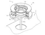
- the cooling unit 3 can be provided with a rotation mechanism that integrally rotates the work W and the restraint mold 33 that holds the work W in the cooling liquid 36 around the axis of the work W.
- FIG. 11 shows an example, in which a lifting mechanism is provided on the lifting and lowering table 34.
- the pressing member 31 is provided rotatably around the axis of the work W
- the lifting table 34 is provided with the pins 34 b fitted to the pressing member 31, and the lifting table 34 and the pins provided on the lifting table 34
- the work W disposed between the pressing member 31 and the lifting table 34 by rotationally driving the lifting table 34 in a state in which the pressing member 31 fitted with 34 b is immersed in the cooling fluid 36
- the constraining mold 33 can be integrally rotated around the axis of the workpiece W. In this way, since the workpiece W immersed in the coolant 36 can be uniformly cooled, the shape accuracy of the workpiece W after the completion of quenching can be further enhanced.
- the cooling unit 3 stirs the cooling fluid 36 when at least the work W is immersed in the cooling fluid 36.
- a stirring mechanism can also be provided. This arrangement is advantageous in uniformly cooling the workpiece W immersed in the cooling fluid 36, as in the case where the cooling unit 3 is provided with a rotation mechanism.
- the restraint die 33 is fixedly disposed in the coolant 36 as shown in FIGS. 12A and 12B. It is also possible to set up.
- the constraining mold 33 shown in FIGS. 12A and 12B restrains the outer peripheral surface of the work W by its inner peripheral surface, and has an axial dimension obtained by adding the axial dimensions of the two works W together.
- the work W transferred to the internal space (second space B) of the hardening preparation chamber 6 is disposed on the upper side of the constraining die 33 (the work W press-fitted to the inner periphery of the constraining die 33).
- the pressing member 31 is moved downward and pressurized downward, the immersion of the work W in the cooling liquid 36 and the restraint of the work W outer peripheral surface by the restraint die 33 simultaneously proceed .
- the two workpieces W arranged on the inner periphery of the restraint die 33 as the pushing of the subsequent workpiece W to the inner periphery of the restraint die 33 is completed,
- the workpiece W on the side is released from the constraining mold 33.
- the “processing to immediately prior to the start of the constraint of the outer peripheral surface of the workpiece by the constraint type” in the present invention is the processing of the workpiece W transferred to the second space B.
- the lower end surface of the pressure member 31 is brought into contact with the upper end surface. Further, in this case, the lifting table 34 used in the embodiment described above is not necessarily required, and if an appropriate receiving member for receiving the work W released from the mold is disposed immediately below the pressing member 31. Good.
- the outer ring of the rolling bearing is taken as an example of the work W, and the heat treatment apparatus 1 is used to cool and harden the work W in a state where the outer peripheral surface of the work W is restrained by the constraining die 33.
- the heat treatment apparatus 1 quench-hardens the workpiece W (for example, the base material of the inner ring of the rolling bearing) which is preferably used to prevent the collapse of the shape accuracy (especially roundness) of the inner peripheral surface accompanying quenching. It can also be preferably used when applying FIG. 13 shows an example, in which a restraining die 33 ′ capable of restraining the inner peripheral surface of the work W is attached and fixed to the lower end surface of the pressure member 31.
- the operation mode of the cooling unit 3 constituting the heat treatment apparatus 1 and the mode change of the shape of the work W accompanying immersion in the cooling liquid 36 are basically the same as those described with reference to FIGS. 5 and 10. It is similar to In short, when the workpiece W is immersed in the cooling fluid 36, first, the diameter reduction deformation is performed and then the diameter expansion deformation is performed. For this reason, the inner circumferential surface of the workpiece W is restrained by the constraining die 33 'at the initial stage immersed in the coolant 36, but is basically not restrained by the constraining die 33' at the releasing stage .
- the shape accuracy of the inner circumferential surface of the workpiece W can not be increased as much as when the outer circumferential surface of the workpiece W described above is restrained by the constraining die 33, but the inside of the workpiece W is cooled in the process of cooling and quenching the workpiece W. Since the circumferential surface is temporarily restrained by the outer circumferential surface of the constraining mold 33 ', the shape accuracy of the inner circumferential surface of the work W is enhanced as compared with the case where the so-called type constrained quenching employed in the present invention is not employed. Can.
- FIG. 14 is an example thereof, and is a partial perspective view of a heating device 60 according to another embodiment of the present invention.
- the heating device 60 shown in the figure is a heating device configured to be able to inductively heat the work W one by one, and has a telescopic cylinder rod 61a provided with a flange portion 61b on the tip of which the work W can be mounted.
- the outer diameter side coil 62 is held by a coil holding member made of an insulating material indicated by reference numeral 64.
- the work W introduced into the internal space (first space A) of the heating chamber 5 is induction heated as follows, and the internal space of the passage chamber 7 (passage C Carried out).
- the atmosphere in the enclosed space D is made non-oxidative, and the atmosphere in the substitution chamber 8 into which the work W is charged is made non-oxidative, and then the inlet side opening 4a is
- the workpiece W is opened and carried into the first space A of the enclosed space D.
- the inlet side opening 4a is closed, and the cylinder rod 61a of the support member 61 is extended to place it on the flange portion 61b.
- the workpiece W is raised and introduced between the outer diameter side coil 62 and the inner diameter side coil 63 in the energized state, and the workpiece W is held at this position for a certain period of time.
- the workpiece W is induction-heated to the target temperature.
- the cylinder rod 61a of the support member 61 is shortened, and the heated work W is lowered together with the flange portion 61b.
- the workpiece W after completion of heating is paid out toward the passage C by an appropriate means not shown.
- the workpiece W after completion of heating can be delivered to the passage C at the same height level as the introduction position of the workpiece W into the support member 61.
- induction heating of the work W by the heating device 60 can be efficiently performed.
- the atmosphere of the enclosed space for the heat treatment and the cooling treatment can be reduced in a short time while suppressing the fluctuation of the liquid level of the coolant.
- the productivity of the heat treatment can be improved.
- the heating device 60 of the said structure is employ
- adopted it is possible to make the height dimension of the sealed chamber 4 (especially heating chamber 5) small compared with the case where the heating device 20 shown in FIG.
- the advantage that the heat treatment apparatus 1 can be made compact can be enjoyed together.
Landscapes
- Chemical & Material Sciences (AREA)
- Engineering & Computer Science (AREA)
- Mechanical Engineering (AREA)
- Physics & Mathematics (AREA)
- Thermal Sciences (AREA)
- Crystallography & Structural Chemistry (AREA)
- Materials Engineering (AREA)
- Metallurgy (AREA)
- Organic Chemistry (AREA)
- General Engineering & Computer Science (AREA)
- Combustion & Propulsion (AREA)
- Power Engineering (AREA)
- Electromagnetism (AREA)
- Heat Treatment Of Articles (AREA)
Abstract
本発明に係るワークの熱処理方法は、ワークの加熱工程S2と、加熱工程S2で加熱されたワークWを冷却液36中に浸漬させることで冷却して所定の熱処理を施す冷却工程S3とを備えると共に、加熱工程S2の前に、密閉空間Dの雰囲気を非酸化性雰囲気とし、ワークWを密閉空間Dに搬入可能な状態とする準備工程S1をさらに備える。準備工程S1では、密閉空間Dへの非酸化性ガスGaの供給と、密閉空間Dの排気とを併せて行うと共に、これら給排気を密閉空間Dの気圧に応じて制御することで、密閉空間Dの雰囲気を非酸化性雰囲気に置換する。
Description
本発明は、ワークの熱処理方法及び熱処理装置に関し、特にワークを加熱した後に冷却することで所定の熱処理を施すための技術に関する。
例えば、転がり軸受の軌道輪のように、SUJ2等の鋼材からなる環状部材の製造過程においては、環状部材に必要とされる機械的強度等を付与するための熱処理(焼入硬化処理)が実施される。この熱処理は、環状部材の基材(環状のワーク)を狙い温度にまで加熱する加熱処理が実施される加熱工程や、加熱されたワークを冷却して焼入れする冷却処理が実施される冷却工程などを含む。加熱工程は、メッシュベルト型連続炉などの雰囲気加熱炉、あるいは、誘導加熱装置を用いて実施することができる。特に、誘導加熱であれば、ワークのみを直接加熱することができるために高いエネルギー効率を達成できることに加え、コンパクトな熱処理装置を実現できる、という利点がある。
ところで、上記のワークに対する加熱処理や冷却処理を、酸素が存在する雰囲気で実施すると、ワークの表面に高い確率で酸化スケールが生成される。ワーク表面に生成された酸化スケールは、ワークの光輝性を奪って外観品質を低下させるだけでなく、コンタミの発生原因にもなり得るため、研磨、研削あるいはショットブラストなどの適宜の手段によって完全に除去するのが好ましい。しかしながら、酸化スケールを完全に除去するのは容易ではなく、特に、微小な穴や凹凸を有する複雑な形状のワーク表面に酸化スケールが生成された場合、酸化スケールを完全に除去するには多大な工数を要する。従って、熱処理に伴う酸化スケールの生成が問題となる場合には、例えば下記特許文献1及び特許文献2に開示されているように、加熱処理や冷却処理を含む一連の熱処理工程を非酸化性雰囲気で実施することが望ましい。
しかしながら、特許文献1及び特許文献2に開示されている熱処理装置は、非酸化性雰囲気にすることのできる容器内に、ワークを狙い温度に誘導加熱する加熱部と、加熱後のワークを冷却する冷却部とを上下に並べて設け、適宜の手段で保持した一のワーク(1個のワーク)を加熱部で狙い温度に誘導加熱した後、加熱されたワークを冷却部の配設位置まで下降させて、ワークに向けた冷却液の噴射によりワークを冷却し焼入れするように構成されている。このような構成の熱処理装置では、一のワークに対する熱処理(加熱及び加熱後の冷却)が完了するまで後続のワークに対して何らの処理も施すことができない。従って、処理効率が低く、転がり軸受の軌道輪のような量産部品の製造過程で使用する熱処理装置としては好ましくない。
上記問題を解決するべく、本出願人は、特願2017-174547明細書において新たな熱処理装置及び熱処理方法を提案している。この熱処理装置及び熱処理方法は、開閉可能なワークの入口側開口部を有し加熱工程を実施する第1空間と、第1空間とつながりワークを浸漬させる冷却液の液面でワークの出口側開口部を閉口した第2空間とを共に密閉空間とし、この密閉空間を非酸化性雰囲気とした状態で、加熱及び冷却を行うものである。
ところで、特願2017-174547明細書において提案しているように、非酸化性雰囲気下でワークに加熱処理と冷却処理を施すためには、ワークを密閉空間に搬入する前に、予め密閉空間の雰囲気を非酸化性雰囲気に置換してワークを搬入し得る環境を準備しておく必要がある。この場合、非酸化性雰囲気への置換は短時間で行うことが望ましく、例えば非酸化性のガスを密閉空間に大量に送り込む方法が考えられる。あるいは、密閉空間を急速に排気する方法が考えられる。
しかしながら、このように大量の非酸化性ガスを密閉空間に供給した場合には、密閉空間の気圧が上昇する。そのため、例えば特願2017-174547明細書において提案しているように、密閉空間の出口(ワークの出口側開口部)が冷却液の液面で閉口される構造をとる場合、冷却液の液面が押し下げられるおそれが高まる。一方、密閉空間を急速に排気した場合には、密閉空間の雰囲気が減圧される。そのため、上述のように冷却液の液面で密閉空間の出口が閉口される構造をとる場合、出口側開口部を介して冷却液が密閉空間に引き込まれるおそれが高まる。このように冷却液の液面レベルが不安定だと、ワークの冷却制御にも支障を来すおそれがある。これを回避するためには、例えば大気圧よりやや高い圧力のガスを密閉空間に供給し、あるいは密閉空間の気圧が大気圧よりやや低くなる程度で、ゆっくりと密閉空間を排気する必要があるが、これら何れの方法をとった場合でも、非酸化性雰囲気への置換に多大な時間を要し、生産性の低下を招く。
以上の実情に鑑み、本明細書では、短時間で、かつ冷却液の液面レベルの変動を抑えつつ、加熱処理及び冷却処理のための密閉空間の雰囲気を非酸化性雰囲気に置換することで、熱処理に係る生産性の向上を図ることを、解決すべき技術課題とする。
前記課題の解決は本発明に係るワークの熱処理方法によって達成される。すなわちこの熱処理方法は、ワークを加熱する加熱工程と、加熱工程で加熱されたワークを冷却液中に浸漬させることによって、ワークを冷却して所定の熱処理を施す冷却工程とを備え、加熱工程を実施する第1空間にワークの入口側開口部が設けられ、第1空間とつながり冷却液の液面に接する第2空間にワークの出口側開口部が設けられ、入口側開口部を閉口しかつ出口側開口部を冷却液の液面で閉口することで第1空間と第2空間とを共に密閉し、この密閉空間を非酸化性雰囲気とした状態で、加熱工程と冷却工程を実施するワークの熱処理方法であって、加熱工程の前に、密閉空間の雰囲気を非酸化性雰囲気とし、ワークを密閉空間に搬入可能な状態とする準備工程をさらに備え、準備工程では、密閉空間への非酸化性ガスの供給と、密閉空間の排気とを併せて行うと共に、これら非酸化性ガスの供給と密閉空間の排気を密閉空間の気圧に応じて制御する点をもって特徴付けられる。なお、ここでいう「非酸化性雰囲気」とは、酸素が一切存在しない雰囲気のみならず、ワークの表面に酸化スケールが生成されない程度に酸素がわずかに存在する雰囲気(例えば、酸素濃度が100ppm以下)を含む概念である。同様に、ここでいう「非酸化性ガス」とは、酸素が一切含有されないガスのみならず、ワークの表面に酸化スケールが生成されない程度に酸素がわずかに含まれるガス(例えば、酸素濃度が100ppm以下)を含む概念である。後述する本発明に係る熱処理装置においても同様である。
このように、本発明に係る熱処理方法では、加熱工程の前に、密閉空間の雰囲気を非酸化性雰囲気とし、ワークを密閉空間に搬入可能な状態とする準備工程において、密閉空間への非酸化性ガスの供給と、密閉空間の排気とを併せて行うようにした。これにより、例えば非酸化性ガスを供給するだけの場合や密閉空間を排気するだけの場合と比べて非酸化性雰囲気への置換速度を高めることができる。よって、熱処理装置の稼働を素早く開始することができ、生産性の向上が可能となる。また、本発明に係る熱処理方法では、これら非酸化性ガスの供給と密閉空間の排気を密閉空間の気圧に応じて制御するようにしたので、給気量や排気量を上げたとしても、密閉空間の気圧を予め設定した範囲内で維持することができる。従って、冷却液の液面レベルを安定させつつ、密閉空間の雰囲気を迅速に非酸化雰囲気に置換することが可能となる。
もちろん、本発明に係る熱処理方法によれば、密閉空間で加熱処理を施したワークは密閉空間に隣接する冷却液中で冷却され、所定の熱処理が施される。そのため、一のワークが加熱工程を終えて冷却される際(冷却液中に浸漬される際)、次のワークに密閉空間で加熱処理を施すことができ、あるいは加熱処理後のワークを冷却液の液面に接する第2空間まで搬送し待機させることができる。これにより、複数のワークに対する加熱処理と冷却処理とを非酸化性雰囲気で同時進行することができる。よって、ワークの表面に酸化スケールを生成させることなく、複数のワークに対して効率良く熱処理を施すことができ、量産部品の製造にも対応することが可能となる。
また、本発明に係るワークの熱処理方法においては、密閉空間の気圧を測定し、測定した気圧が気圧上限しきい値以上の場合、密閉空間への非酸化性ガスの供給を停止し、かつ密閉空間の排気を継続するよう制御してもよい。
このように、測定した密閉空間の気圧が大気圧よりも一定値以上高い(気圧上限しきい値以上の)場合に、非酸化性非ガスの供給を停止することで、非酸化性ガスの流入に伴う密閉空間の気圧の上昇を抑えることができる。一方で、密閉空間の排気は継続することで、酸素濃度及び気圧の低減化を図ることができる。よって、気圧を所定範囲内に戻しながら、密閉空間を目標とする酸素濃度の雰囲気(非酸化性雰囲気)に近づけることができる。
あるいは、本発明に係るワークの熱処理方法においては、密閉空間の気圧を測定し、測定した気圧が気圧下限しきい値以下の場合、密閉空間への非酸化性ガスの供給を継続し、かつ密閉空間の排気を停止するよう制御してもよい。
このように、測定した密閉空間の気圧が大気圧とほとんど変わらないかそれ以下(気圧下限しきい値以下)の場合には、密閉空間の排気を停止することで、排気に伴う気圧の低下を抑えることができる。一方で、密閉空間への非酸化ガスの供給を継続することで、酸素濃度の低下及び気圧の上昇を図ることができる。よって、気圧を許容範囲内に戻しながら、密閉空間を目標とする酸素濃度の雰囲気(非酸化性雰囲気)に近づけることができる。
あるいは、本発明に係るワークの熱処理方法においては、密閉空間の気圧を測定し、測定した気圧が気圧下限しきい値より大きくかつ気圧上限しきい値未満の場合、密閉空間の酸素濃度を測定し、測定した酸素濃度が酸素濃度しきい値以上の場合、密閉空間への非酸化性ガスの供給を継続し、かつ密閉空間の排気を継続するよう制御してもよい。
このように、測定した密閉空間の気圧が許容範囲内に収まっている場合には、非酸化性ガスの供給と密閉空間の排気を継続することで、引き続き気圧を安定させた状態で効果的に密閉空間の酸素濃度を低減化できる。また、気圧を安定させた状態で効果的に密閉空間の酸素濃度が低減化されている場合、酸素濃度を測定し、測定した酸素濃度が目標値以下に達しているか否か判定する。そして、未だ目標値以下に達していないと判定した場合には、上述した気圧制御を行いながら給排気を続行する。これにより、確実に密閉空間を非酸化性雰囲気に置換することができる。
あるいは、本発明に係るワークの熱処理方法においては、密閉空間の気圧を測定し、測定した気圧が気圧下限しきい値より大きくかつ気圧上限しきい値未満の場合、密閉空間の酸素濃度を測定し、測定した酸素濃度が酸素濃度しきい値未満の場合、密閉空間への非酸化性ガスの供給を停止し、かつ密閉空間の排気を停止するよう制御してもよい。
このように密閉空間の酸素濃度が目標範囲に達した場合には、もはやこれ以上の給排気は不要であるから、非酸化性ガスの供給を停止すると共に密閉空間の排気を停止する。これにより、密閉空間の雰囲気を非酸化雰囲気に置換した状態で、維持することが可能となる。
また、本発明に係るワークの熱処理方法においては、密閉空間の気圧を一定時間おきに測定し、測定した気圧が気圧下限しきい値より大きくかつ気圧上限しきい値未満の場合、密閉空間の酸素濃度を測定し、測定した酸素濃度が酸素濃度しきい値未満となるまで、測定した気圧に応じた非酸化性ガスの供給と密閉空間の排気の制御を繰り返し行ってもよい。
このように、一定時間おきに気圧と酸素濃度を測定し、各数値が所定範囲内に収まるまで、測定した気圧に応じた給排気の制御を繰り返すことで、精度よく密閉空間の圧力を制御しながら酸素濃度の低減化を迅速に図ることができる。
また、本発明に係るワークの熱処理方法においては、入口側開口部を閉口した状態で、入口側開口部を介して第1空間と隣接する置換室内にワークを搬入し、密閉空間の雰囲気を非酸化性雰囲気とし、かつ置換室内の雰囲気を大気雰囲気から非酸化性雰囲気に置換した後、入口側開口部を開口して、ワークを密閉空間に搬入してもよい。
このように入口側開口部を閉口した状態で、第1空間と隣接する置換室内にワークを搬入し、上述のように密閉空間の雰囲気を非酸化性雰囲気とし、かつ置換室内の雰囲気を非酸化性雰囲気に置換した後、ワークを密閉空間に搬入することで、第1空間の入口側開口を開口した際、置換室から酸化性の気体が密閉空間に流入する事態を回避できる。よって、密閉空間の雰囲気を非酸化性雰囲気に保った状態で、ワークを密閉空間に搬入することが可能となる。
また、本発明に係るワークの熱処理方法においては、加熱工程でワークを狙い温度にまで誘導加熱すると共に、冷却工程で加熱されたワークを冷却して焼入れを施してもよい。
このように誘導加熱でワークを狙い温度にまで加熱することで、ワークのみを直接加熱することができ、高いエネルギー効率を達成することができると共に、密閉空間を含めた熱処理設備全体をコンパクトにできる。密閉空間がコンパクトになれば、置換容積も小さくなるため、急速な非酸化雰囲気への置換が比較的容易に達成できる。
また、以上の説明に係るワークの熱処理方法は、熱処理装置の稼働までに要する時間を短縮することにより、ワークの生産性向上を可能とするものであるから、例えば転がり軸受の軌道輪のような量産部品に熱処理を施すための方法として好適である。
また、前記課題の解決は、本発明に係るワークの熱処理装置によっても達成される。すなわち、この熱処理装置はワークを加熱する加熱部と、加熱部で加熱されたワークを冷却液中に浸漬させることによって、ワークを冷却して所定の熱処理を施す冷却部とを備え、加熱部は、ワークの加熱を実施する第1空間を有すると共に、冷却部は、第1空間とつながり冷却液の液面に接する第2空間を有し、第1空間にワークの入口側開口部が設けられ、第2空間にワークの出口側開口部が設けられ、入口側開口部を閉口しかつ出口側開口部を冷却液の液面で閉口することで第1空間と第2空間が共に密閉され、この密閉空間が非酸化性雰囲気とされるワークの熱処理装置であって、密閉空間の気圧を測定する気圧測定器と、密閉空間に非酸化性ガスを供給する給気装置と、密閉空間の排気を行う排気装置、及び、給気装置による密閉空間への非酸化性ガスの供給と、排気装置による密閉空間の排気とを併せて行うと共に、これら給排気を気圧測定器で測定した気圧に応じて制御する制御部とをさらに備える点をもって特徴付けられる。
上記構成の熱処理装置であれば、上述した本発明に係る熱処理方法と同様に、非酸化性雰囲気への置換速度を向上させることができる。よって、熱処理装置の稼働を素早く開始することができ、生産性の向上が可能となる。また、非酸化性ガスの供給と密閉空間の排気を密閉空間の気圧に応じて制御できるので、給気量や排気量を上げたとしても、密閉空間の気圧を予め設定した範囲内で維持することができる。従って、冷却液の液面レベルを安定させつつ、密閉空間の雰囲気を迅速に非酸化雰囲気に置換することが可能となる。
以上述べたように、本発明に係るワークの熱処理方法及び熱処理装置によれば、短時間で、かつ冷却液の液面レベルの変動を抑えつつ、加熱処理及び冷却処理のための密閉空間の雰囲気を非酸化性雰囲気に置換することができるので、熱処理装置の稼働までに要する時間を短縮して、熱処理に係るワークの生産性を向上させることが可能となる。
以下、本発明の一実施形態を図面に基づいて説明する。
図1は、本発明の一実施形態に係る熱処理装置の全体構造を示す斜視図であり、図2は、熱処理装置の正面図である。図1及び図2に示す熱処理装置1は、SUJ2等の鋼材からなる環状のワークW(本実施形態では、転がり軸受の外輪の基材)を、図2中に二点鎖線で示す経路に沿って送りながらワークWに焼入硬化処理を施すように構成された、いわゆる連続式の熱処理装置1である。従い、この熱処理装置1は、ワークWの送り方向に沿って、ワークWを狙い温度(焼入れ温度)にまで誘導加熱する加熱工程S2(後述する図7Aを参照)が実施される加熱部2と、加熱部2で加熱されたワークWを冷却して焼入れする冷却工程S3(後述する図7Aを参照)が実施される冷却部3とを備える。さらに、この熱処理装置1は、非酸化性雰囲気下で加熱工程S2及び冷却工程S3が実施できるように構成されている。また、後述するように、この熱処理装置1は、密閉室4の内部空間である密閉空間Dの給排気制御システム40をさらに備える。以下、まず熱処理装置1の構成について説明し、次いで熱処理装置1を用いた熱処理方法の一例を説明する。
図3に示すように、加熱部2は、加熱装置20、加熱室5、置換室8、及び通路室7を備える。
加熱装置20は、ワークWを狙い温度にまで誘導加熱するためのものであって、本実施形態では、図3及び図4に示すように、複数のワークWを段積み状態で支持可能な支持部材21と、支持部材21で支持されたワークWの径方向外側に配置された加熱コイル22と、支持部材21の下方側に配置され、支持部材21にワークW(経路上流側から搬送される後続のワークW)を供給するワーク供給手段23とを備える。
支持部材21は、支持すべきワークWの周方向に離間した複数箇所(例えば3箇所)に配設されている。各支持部材21は、支持すべきワークWの径方向に沿って進退移動可能に設けられており、ワーク供給手段23によって下方側からワークWが供給されるのに伴って支持すべきワークWの径方向外側に移動してワークWを受け入れ、ワークWを受け入れた後には、支持すべきワークWの径方向内側に移動してワークWを下方から支持する。
加熱コイル22は、例えば、銅管等の導電性金属からなる管状体を螺旋状に巻き回したいわゆる多巻きコイルからなり、支持部材21で支持されたワークWと同軸に配置されている。加熱コイル22としては、ワークWの軸方向寸法の数倍~数十倍程度の全長(軸方向)寸法を有するものが使用される。このような全長寸法の加熱コイル22を使用することにより、支持部材21によって段積み状態で支持された複数のワークWが通電状態の加熱コイル22の内側領域を上側に送られていくのに伴って、各ワークWが順次狙い温度にまで誘導加熱される。
ワーク供給手段23は、例えば、支持部材21で支持されたワークWと同軸に配置された伸縮自在のシリンダロッド23aを有する動力シリンダ(油圧シリンダ、エアシリンダ、あるいは電動シリンダ)で構成される。シリンダロッド23aの先端には、ワークWを載置可能なフランジ部23bが設けられている。
以上の構成を有する加熱装置20は、本発明でいう第1空間Aとしての加熱室5の内部空間に配設されており、加熱室5の上流側(ワークWの送り方向後方側)に置換室8が、加熱室5の下流側(ワークWの送り方向前方側)に通路室7がそれぞれ加熱室5と隣接して配置されている。
ここで、加熱室5は、図2に示すように、通路室7及び後述する焼入れ準備室6と協働して、室内雰囲気(熱処理装置1の稼働中における室内雰囲気)が非酸化性雰囲気に保たれる密閉室4を形成している。密閉室4は、ワークWの送り方向に沿って、加熱室5、通路室7及び焼入れ準備室6を順に配置してなり、図3及び図5に示すように、第1空間Aとしての加熱室5の内部空間と、本発明における第2空間Bとしての焼入れ準備室6の内部空間とは、両室5,6間に設けられた通路室7の内部空間(通路C)を介してつながっている。従って、本実施形態では、密閉室4は、相互に分離して設けられた第1空間Aと第2空間B、及び通路Cとを有しており、第1空間Aと第2空間B、及び通路Cとで本発明における密閉空間Dを構成している。密閉室4は、さらに、加熱室5の内部空間にワークWを投入するための入口側開口部4a(図3を参照)と、焼入れ準備室6の底壁に設けられた出口側開口部4b(図5を参照)とを有する。入口側開口部4aは、図3に示す開閉手段(第2の開閉手段12)によって開口又は閉口され、出口側開口部4bは、図5に示すように、冷却液貯留槽35に貯留された冷却液36の液面によって常に閉口されている。密閉室4の内部空間(密閉空間D)に係る給排気制御システム40については後述する。
置換室8は、ワークWを加熱室5の内部空間に投入する際に、加熱室5を含む密閉室4の室内雰囲気(密閉空間Dの雰囲気)を非酸化性雰囲気に保つ目的で設置されている。そのため、図示は省略しているが、置換室8には、置換室8内の雰囲気を非酸化性雰囲気に置換可能とするため、非酸化性ガスを置換室8内に供給するための給気装置や、置換室8内を排気するための排気装置、給気装置と置換室8内とを接続する給気管、及び排気装置と置換室8内とを接続する排気管が設けられている。
図3に示すように、置換室8には、その内部空間にワークWを投入するための開口部8aが設けられており、この開口部8aは、開閉手段(第1の開閉手段11)によって開口又は閉口可能とされる。第1の開閉手段11には任意の開閉機器が採用でき、例えば昇降式のシャッターを採用することができる。
置換室8と加熱室5との間には開閉手段(第2の開閉手段12)が設けられており、この第2の開閉手段12によって密閉室4(密閉空間D)の入口側開口部4aを開口又は閉口可能としている。この第2の開閉手段12は、開口部8aが第1の開閉手段11により閉状態から開状態に切り替わったとき、密閉室4(加熱室5)の入口側開口部4aを閉状態とするようになっている。なお、第2の開閉手段12にも任意の開閉機器が採用でき、例えば昇降式のシャッターを採用することができる。
加熱部2は、図示は省略するが、置換室8の内部空間に投入されたワークWを加熱室5の内部空間に移送するための移送手段を有する。この移送手段としては、例えば、置換室8及び加熱室5の底部に跨るようにして配設された搬送コンベア、あるいは動力シリンダ(油圧シリンダ、エアシリンダ、電動シリンダ)などを採用することができる。
通路室7の内部空間は、加熱装置20で狙い温度にまで加熱され、加熱装置20の外側(加熱コイル22の上側)に排出された加熱完了後のワークWを、第2空間Bとしての焼入れ準備室6の内部空間に向けて移送するための通路Cとして活用される。通路室7には、図示しない搬送コンベア等の移送手段が設けられており、この移送手段により加熱装置20の外側に排出されたワークWを第1空間Aから第2空間Bに移送可能としている。
冷却部3は、上述した通り、加熱部2で狙い温度にまで加熱されたワークWを冷却して焼入れする冷却工程が実施される領域であり、本実施形態の冷却部3は、ワークWの外周面を拘束型33で拘束した状態でワークWを冷却(焼入れ)可能に構成されている。図1、図2、及び図5に示すように、冷却部3は、通路室7を介して加熱室5の下流側に隣接して配設された焼入れ準備室6と、プレス装置30と、拘束型33と、昇降テーブル34、及び冷却液貯留槽35とを備える。
プレス装置30は、通路室7の内部空間(通路C)を介して焼入れ準備室6の内部空間(第2空間B)に移送されてきたワークWを下方側に加圧し、ワークWを冷却液貯留槽35に貯留された冷却液36中に浸漬させる加圧部材31と、加圧部材31を昇降可能に保持した昇降ユニット32とを備える。本実施形態では、加圧部材31の下端に拘束型33が取り付け固定されており、拘束型33は加圧部材31と一体的に昇降可能とされる。図1及び図2に示すように、昇降ユニット32は焼入れ準備室6の外側に配置されており、図5に示すように、加圧部材31、加圧部材31に取り付け固定された拘束型33、さらには下端に加圧部材31を保持した軸部材の一部のみが第2空間Bに配置されている。加圧部材31を保持した軸部材は、焼入れ準備室6の天井壁を貫通する貫通穴に挿通されており、この貫通穴(貫通穴の内壁面と軸部材の外径面との間の隙間)は図示しないシール材で封止されている。
図5に示すように、冷却液貯留槽35は、焼入れ準備室6の下方側に設置され、ワークWを冷却して焼入れするための冷却液36を貯留している。冷却液36としては、公知の焼入れ油、あるいは水溶性焼入れ液などを使用することができる。本実施形態では、冷却液貯留槽35の上部は開口しており、この開口部は、密閉室4(焼入れ準備室6)の壁部によって第1開口部35aと第2開口部35bとに区分されている。焼入れ準備室6に設けられた密閉室4(密閉空間D)の出口側開口部4bは、冷却液貯留槽35に貯留された冷却液36のうち、第1開口部35a内に存在する冷却液36の液面で閉口されている。
図5に示すように、昇降テーブル34は、加圧部材31の直下に配設されて冷却液36中で昇降する。昇降テーブル34の上端面34aはワークWを載置する載置面とされ、昇降テーブル34が上昇限に位置したときには、昇降テーブル34の上端面34aが冷却液貯留槽35に貯留された冷却液36の液面よりも上方に位置して、通路室7の内部空間を移送されてきたワークWを受け取る。
冷却液貯留槽35の内部(冷却液36中)には、拘束型33から離型された焼入れ済のワークWを昇降テーブル34から払い出すための払い出し手段(図示は省略)と、払い出されたワークWを受け取って冷却液貯留槽35(熱処理装置1)の外側に排出するための排出手段37とが設けられている。この排出手段37としては、例えば、上記の昇降テーブル34とは別に設けられた昇降テーブルを採用することができる。このワーク排出用昇降テーブルは、冷却液貯留槽35のうち、第2開口部35bの直下位置で昇降可能に設けられており、焼入れ済のワークWを第2開口部35bから冷却液貯留槽35の外側、すなわち熱処理装置1の外側に排出する。
次に、密閉室4の内部空間(密閉空間D)に係る給排気制御システム40について説明する。
この給排気制御システム40は、図6に示すように、密閉室4の内部空間である密閉空間Dの酸素濃度を測定する酸素濃度測定器41と、密閉空間Dの気圧を測定する気圧測定器42と、密閉空間Dに非酸化性ガスGaを供給する給気装置43と、密閉空間Dの排気を行う排気装置44と、給気装置43及び排気装置44の駆動を制御する制御部45とを備える。
酸素濃度測定器41は例えば酸素濃度計であり、密閉空間Dの酸素濃度を測定可能なように密閉室4に取付けられている。気圧測定器42は例えば圧力センサであり、密閉空間Dの酸素濃度を測定可能なように密閉室4に取付けられている。
給気装置43は、本実施形態では、給気バルブ46と、非酸化性ガスGaが貯留されるリザーブタンク47とを有し、密閉空間Dと給気バルブ46、給気バルブ46とリザーブタンク47とがそれぞれ給気管48により接続されている。また、排気装置44は、本実施形態では、排気ポンプ49を有し、密閉空間Dと排気ポンプ49とが排気管50により接続されている。以上の構成により、リザーブタンク47から排出された非酸化性ガスGaが、給気管48を通って給気バルブ46に達し、給気バルブ46が開いている状態で、給気バルブ46を通過し、さらにはその下流側の給気管48を通って、密閉空間Dに供給されるようになっている。本実施形態では、大気圧よりも高い気圧(例えば大気圧+0.01MPa以上)の非酸化性ガスGaがリザーブタンク47に貯溜されており、給気バルブ46を開くことで、相対的に気圧の低い密閉空間Dに非酸化性ガスGaが自動的に流れ込むようになっている。また、排気ポンプ49の駆動により、密閉空間Dを満たす気体Gbが、排気管50を通って(さらに排気ポンプ49内を通過して)熱処理装置1の外側に排出されるようになっている。なお、非酸化性ガスとしては、任意の種類のガスが使用可能であり、例えば窒素ガス、ヘリウムガス、アルゴンガスなどの不活性ガスや、水素ガス、一酸化炭素ガス、二酸化窒素ガス、硫化水素ガス、二酸化硫黄ガスなどの還元性ガスが使用可能である。
これら酸素濃度測定器41、気圧測定器42、給気装置43(給気バルブ46)、排気装置44(排気ポンプ49)は何れも、図6中の一点鎖線で示すように、制御部45と電気的に接続されている。これにより、酸素濃度測定器41で測定された酸素濃度の測定値は制御部45に送られ、気圧測定器42で測定された気圧の測定値は制御部45に送られるようになっている。また、制御部45からの指令が給気バルブ46と排気ポンプ49とにそれぞれ送られることで、指令に基づいて給気バルブ46と排気ポンプ49の駆動を制御可能としている。
制御部45には、予め所定の制御プログラムが記憶されている。本実施形態では、主に二つの制御プログラムが記憶されている。このうち、第1制御プログラムは、加熱工程S2の前の準備工程S1(図7Aを参照)において実施されるプログラムであり、第2制御プログラムは、準備工程S1の後の加熱工程S2及び冷却工程S3において実施されるプログラムである。
各制御プログラムについて具体的に述べると、第1制御プログラムは、後述する準備工程S1(図7Aを参照)において、密閉空間Dへの非酸化性ガスGaの供給と、密閉空間Dの排気とを併せて行うと共に、これら給排気を密閉空間Dの気圧に応じて制御するように設定されている。本実施形態では、図8に示すように、一定時間おきに密閉空間Dの気圧を測定し、測定した気圧の値に応じて三パターンの制御を行う。すなわち、(1)測定した気圧が気圧上限しきい値(本実施形態では大気圧+100Pa)以上の場合、密閉空間Dへの非酸化性ガスGaの供給を停止し、かつ密閉空間Dの排気を継続するよう給気装置43と排気装置44を制御する。あるいは、(2)測定した気圧が気圧下限しきい値(本実施形態では大気圧+1Pa)以下の場合、密閉空間Dへの非酸化性ガスGaの供給を継続し、かつ密閉空間Dの排気を停止するよう給気装置43と排気装置44を制御する。あるいは、(3)測定した気圧が気圧下限しきい値(大気圧+1Pa)より大きくかつ気圧上限しきい値(大気圧+100Pa)未満の場合、併せて密閉空間の酸素濃度を測定する。そして、(3-1)測定した酸素濃度が予め設定しておいた酸素濃度しきい値(例えば100ppm)以上の場合、密閉空間Dへの非酸化性ガスGaの供給を継続し、かつ密閉空間Dの排気を継続するよう給気装置43と排気装置44を制御する。あるいは、(3-2)測定した酸素濃度が上記しきい値(100ppm)未満の場合、密閉空間Dへの非酸化性ガスGaの供給を停止し、かつ密閉空間Dの排気を停止するよう給気装置43と排気装置44を制御する。なお、気圧上限しきい値と気圧下限しきい値は、本実施形態ではそれぞれ大気圧+100Paと大気圧+1Paに設定しているが、もちろんこれに限る必要はなく、ワークWあるいは熱処理の種類等に応じて、適宜変更してもよい。後述する第2制御プログラムにおける気圧上限しきい値あるいは気圧下限しきい値についても同様である。また、酸素濃度のしきい値は、本実施形態では100ppmに設定しているが、ワークWあるいは熱処理の種類によりさらに厳しく密閉空間Dの酸素濃度を管理する必要がある場合、50ppmに設定してもよく、好ましくは20ppmに設定してもよく、より好ましくは10ppm以下に設定してもよい。後述する第2制御プログラムにおける酸素濃度のしきい値についても同様である。
また、第2制御プログラムは、加熱工程S2と冷却工程S3(図7Aを参照)において、密閉空間Dの酸素濃度と気圧を一定時間おきに測定し、測定した酸素濃度と気圧の値に基づいて、密閉空間D内への非酸化性ガスGaの供給を制御すると共に、密閉空間Dの排気を制御するように設定されている。本実施形態では、図9に示すように、測定した酸素濃度が予め設定しておいた酸素濃度しきい値(本実施形態では100ppm)以上の場合、併せて測定した気圧の値に応じて以下の三パターンの制御を行う。すなわち、(1)測定した気圧が予め設定しておいた気圧上限しきい値(本実施形態では大気圧+100Pa)以上の場合、密閉空間Dへの非酸化性ガスGaの供給を停止すると共に、密閉空間Dの排気を継続するよう給気装置43と排気装置44を制御する。あるいは、(2)測定した気圧が予め設定しておいた気圧下限しきい値(本実施形態では大気圧+1Pa)以下の場合、密閉空間Dへの非酸化性ガスGaの供給を継続すると共に、密閉空間Dの排気を停止するよう給気装置43と排気装置44を制御する。そして、(3)測定した気圧が気圧下限しきい値(大気圧+1Pa)より大きくかつ気圧上限しきい値(大気圧+100Pa)未満の場合、密閉空間Dへの非酸化性ガスGaの供給と、密閉空間Dの排気を共に継続するよう給気装置43と排気装置44を制御する。
また、測定した酸素濃度が上記しきい値(100ppm)未満の場合、密閉空間Dへの非酸化性ガスGaの供給を停止すると共に、密閉空間Dの排気を停止するよう給気装置43と排気装置44を制御する。
次に、上記構成の熱処理装置1を用いたワークWの熱処理方法の一例を説明する。
本実施形態に係るワークWの熱処理方法は、図7Aに示すように、準備工程S1と、加熱工程S2と、冷却工程S3とを備える。また、準備工程S1は、図7Bに示すように、密閉空間Dの雰囲気を非酸化性雰囲気に置換する第1置換工程S11と、置換室8内の雰囲気を非酸化性雰囲気に置換する第2置換工程S12とを有する。以下、図3、図5、及び図6も参照しながら、順に各工程の詳細を説明する。
(S1)準備工程
(S11)第1置換工程
この工程では、まず、熱処理装置1の稼働開始時(熱処理装置1へのワークWの投入前)に、加熱室5、焼入れ準備室6、及び通路室7からなる密閉室4内(第1空間A,第2空間B、及び通路Cからなる密閉空間D)を大気雰囲気から非酸化性雰囲気に置換する(第1置換工程S11)。この雰囲気置換処理は、密閉室4(密閉空間D)の入口側開口部4a及び出口側開口部4bを閉口した状態で、密閉空間Dに接続された給気装置43(給気バルブ46及びリザーブタンク47)を作動させて、密閉空間Dに非酸化性ガスGaを供給すると共に、排気装置44(排気ポンプ49)を作動させて、密閉空間Dに存在する気体(通常、稼働開始時においては大気)Gbを排出することにより行われる。また、これら給気装置43と排気装置44による給排気は、制御部45の第1制御プログラムに基づいて実施される。以下、制御の流れの一例を主に図8に基づいて説明する。
[準備工程における給排気制御の一例]
まず、制御部45からの指令により、密閉室4(密閉空間D)の入口側開口部4a及び出口側開口部4bを閉口し、給気装置43と排気装置44を作動させて、密閉空間Dに非酸化性ガスGaを供給すると共に、密閉空間Dを排気する。本実施形態でいえば、図6に示すように、給気バルブ46を開くことでリザーブタンク47に貯溜されている非酸化性ガスGaが給気管48を通って密閉空間Dに供給される。また、排気ポンプ49の駆動により密閉空間Dに存在する気体Gbが排気管50を通って密閉空間Dの外側(密閉室4の外側)に排出される。これにより、密閉空間Dにおける酸素濃度の低減化処理が開始される。
まず、制御部45からの指令により、密閉室4(密閉空間D)の入口側開口部4a及び出口側開口部4bを閉口し、給気装置43と排気装置44を作動させて、密閉空間Dに非酸化性ガスGaを供給すると共に、密閉空間Dを排気する。本実施形態でいえば、図6に示すように、給気バルブ46を開くことでリザーブタンク47に貯溜されている非酸化性ガスGaが給気管48を通って密閉空間Dに供給される。また、排気ポンプ49の駆動により密閉空間Dに存在する気体Gbが排気管50を通って密閉空間Dの外側(密閉室4の外側)に排出される。これにより、密閉空間Dにおける酸素濃度の低減化処理が開始される。
そして、一定時間おきに、気圧測定器42で密閉空間Dの気圧を自動的に測定する(図8を参照)。ここで、(1)測定した気圧の値が気圧上限しきい値(大気圧+100Pa)以上の場合、制御部45は、密閉空間Dへの非酸化性ガスGaの供給を停止し、かつ密閉空間Dの排気を継続するよう給気装置43と排気装置44に制御指令を送る。本実施形態では、給気バルブ46を閉じ、かつ排気ポンプ49の駆動を継続するよう給気バルブ46と排気ポンプ49に指令を送る。これにより、密閉空間Dの酸素濃度が低減化されつつ、気圧の上昇が抑制され、もしくは気圧の低減化が図られる。
あるいは、(2)測定した気圧が気圧下限しきい値(大気圧+1Pa)以下の場合、制御部45は、密閉空間Dへの非酸化性ガスGaの供給を継続し、かつ密閉空間Dの排気を停止するよう給気装置43と排気装置44に制御指令を送る。本実施形態では、給気バルブ46を開いたままの状態とし、かつ排気ポンプ49の駆動を停止するよう給気バルブ46と排気ポンプ49に指令を送る。これにより、密閉空間Dの酸素濃度が引き続き低減化されつつ、気圧の低下が抑制され、もしくは気圧の増大化が図られる。
あるいは、測定した気圧が気圧下限しきい値(大気圧+1Pa)より大きくかつ気圧上限しきい値(大気圧+100Pa)未満の場合、制御部45は、密閉空間Dの酸素濃度を測定するよう酸素濃度測定器41に指令を送る。そして、(3-1)測定した酸素濃度が予め設定しておいた酸素濃度しきい値(例えば100ppm)以上の場合、密閉空間Dへの非酸化性ガスGaの供給を継続し、かつ密閉空間Dの排気を継続するよう給気装置43と排気装置44に制御指令を送る。本実施形態では、給気バルブ46を開いたままの状態とし、かつ排気ポンプ49の駆動を継続するよう給気バルブ46と排気ポンプ49に指令を送る。これにより、密閉空間Dの気圧が所定の範囲内で安定した状態で、密閉空間Dにおける酸素濃度の低減化が目標範囲(100ppm未満)に向けて進行する。
そして、気圧を上記範囲内に収めた状態で、(3-2)測定した酸素濃度が上記しきい値(100ppm)未満にまで低下したこと、すなわち目標範囲内に至ったことを検知した場合、制御部45は、密閉空間Dへの非酸化性ガスGaの供給を停止し、かつ密閉空間Dの排気を停止するよう給気装置43と排気装置44に制御指令を送る。本実施形態では、給気バルブ46を閉状態とし、かつ排気ポンプ49の駆動を停止する。これにより、密閉空間Dの気圧が所定の範囲(本実施形態では大気圧+1Paより大きく、かつ大気圧+100Pa未満)で、かつ酸素濃度が100ppm未満の状態、すなわち非酸化性雰囲気の状態となる。
(S12)第2置換工程
以上のようにして、密閉空間Dの雰囲気を非酸化性雰囲気に置換した後、入口側開口部4aを閉口した状態で、加熱室5(第1空間A)と隣接する置換室8(図3を参照)内にワークWを搬入し、置換室8の開口部8aを閉口した状態で置換室8内の雰囲気を大気雰囲気から非酸化性雰囲気に置換する(第2置換工程S12)。然る後、入口側開口部4aを開口して、ワークWを密閉空間D内に搬入する。ワークWの搬入後、第2の開閉手段12を閉状態として、密閉空間Dの入口側開口部4aを閉口しておく。これにより、密閉空間Dを非酸化性雰囲気に保った状態で、ワークWを密閉空間Dに搬入することができる。なお、本実施形態では、密閉空間Dの雰囲気を非酸化性雰囲気に置換した後、置換室8内にワークWを搬入して、置換室8内の雰囲気を非酸化性雰囲気に置換する場合を例示したが、もちろんこれには限定されず、例えば予め入口側開口部4aを閉口した状態で置換室8内にワークWを搬入した状態で、第1置換工程S12と第2置換工程S12を実施し、然る後、入口側開口部4aを開口して、ワークWを密閉空間Dに搬入してもかまわない。また、第1置換工程S11と第2置換工程S12の順序に関しても特に問わず、例えば置換室8内にワークWを搬入した状態で第2置換工程S12を実施した後、第1置換工程S11を実施してもよい。
以上のようにして、密閉空間Dの雰囲気を非酸化性雰囲気に置換した後、入口側開口部4aを閉口した状態で、加熱室5(第1空間A)と隣接する置換室8(図3を参照)内にワークWを搬入し、置換室8の開口部8aを閉口した状態で置換室8内の雰囲気を大気雰囲気から非酸化性雰囲気に置換する(第2置換工程S12)。然る後、入口側開口部4aを開口して、ワークWを密閉空間D内に搬入する。ワークWの搬入後、第2の開閉手段12を閉状態として、密閉空間Dの入口側開口部4aを閉口しておく。これにより、密閉空間Dを非酸化性雰囲気に保った状態で、ワークWを密閉空間Dに搬入することができる。なお、本実施形態では、密閉空間Dの雰囲気を非酸化性雰囲気に置換した後、置換室8内にワークWを搬入して、置換室8内の雰囲気を非酸化性雰囲気に置換する場合を例示したが、もちろんこれには限定されず、例えば予め入口側開口部4aを閉口した状態で置換室8内にワークWを搬入した状態で、第1置換工程S12と第2置換工程S12を実施し、然る後、入口側開口部4aを開口して、ワークWを密閉空間Dに搬入してもかまわない。また、第1置換工程S11と第2置換工程S12の順序に関しても特に問わず、例えば置換室8内にワークWを搬入した状態で第2置換工程S12を実施した後、第1置換工程S11を実施してもよい。
(S2)加熱工程
以上のようにして、非酸化性雰囲気の密閉空間DにワークWを搬入した後、ワークWに加熱処理を施す。具体的には、図3に示すように、ワーク供給手段23のフランジ部23b上にワークWを載置する。そして、支持部材21を半径方向外側に退避させた状態でワーク供給手段23のシリンダロッド23aを伸長させることでワークWを支持部材21の上側にまで上昇させ、然る後、支持部材21を半径方向内側に前進させることで支持部材21によりワークWを下方から支持する。以降、後続のワークWが、順次、以上で述べた手順を経て、支持部材21と、支持部材21で支持されたワークWとの間に供給されるのに伴って、支持部材21で支持された全てのワークWに上向きの送り力が付与される。このようして、ワークWは、通電状態の加熱コイル22の内側領域を上方に向けて送られながら狙い温度にまで誘導加熱され、加熱コイル22の上側に排出される(図3及び図4を参照)。加熱コイル22の上側領域に排出された加熱完了後のワークWは、図示外の適宜の手段によって通路室7の内部空間に払い出された後、通路室7の内部空間に設けられた図示外の搬送手段によって焼入れ準備室6の内部空間(すなわち第2空間B)に向けて送られる(以上、図3及び図4を参照)。
以上のようにして、非酸化性雰囲気の密閉空間DにワークWを搬入した後、ワークWに加熱処理を施す。具体的には、図3に示すように、ワーク供給手段23のフランジ部23b上にワークWを載置する。そして、支持部材21を半径方向外側に退避させた状態でワーク供給手段23のシリンダロッド23aを伸長させることでワークWを支持部材21の上側にまで上昇させ、然る後、支持部材21を半径方向内側に前進させることで支持部材21によりワークWを下方から支持する。以降、後続のワークWが、順次、以上で述べた手順を経て、支持部材21と、支持部材21で支持されたワークWとの間に供給されるのに伴って、支持部材21で支持された全てのワークWに上向きの送り力が付与される。このようして、ワークWは、通電状態の加熱コイル22の内側領域を上方に向けて送られながら狙い温度にまで誘導加熱され、加熱コイル22の上側に排出される(図3及び図4を参照)。加熱コイル22の上側領域に排出された加熱完了後のワークWは、図示外の適宜の手段によって通路室7の内部空間に払い出された後、通路室7の内部空間に設けられた図示外の搬送手段によって焼入れ準備室6の内部空間(すなわち第2空間B)に向けて送られる(以上、図3及び図4を参照)。
(S3)冷却工程
この工程では、上述したように、加熱部2(加熱工程)で狙い温度にまで加熱されたワークWを冷却して焼入れする冷却処理が実施される。具体的には、図5に示すように、まず、通路室7の内部空間を移送されてきたワークWを、昇降テーブル34の上端面34aで載置するようにして受け取る。次いで、プレス装置30の昇降ユニット32(図2を参照)を駆動して、加圧部材31及び加圧部材31の下端に取り付け固定された拘束型33を一体的に下降させ、昇降テーブル34の上端面34aに載置されたワークWの外周に拘束型33を配置することにより、拘束型33によるワークWの外周面の拘束が開始される直前状態にする。この状態において、ワークWの外周面と拘束型33の内周面の嵌め合いはすきま嵌め(JIS B 0401-1を参照)とされ、また、拘束型33の下端面と昇降テーブル34の上端面34aとは当接状態にある。
この工程では、上述したように、加熱部2(加熱工程)で狙い温度にまで加熱されたワークWを冷却して焼入れする冷却処理が実施される。具体的には、図5に示すように、まず、通路室7の内部空間を移送されてきたワークWを、昇降テーブル34の上端面34aで載置するようにして受け取る。次いで、プレス装置30の昇降ユニット32(図2を参照)を駆動して、加圧部材31及び加圧部材31の下端に取り付け固定された拘束型33を一体的に下降させ、昇降テーブル34の上端面34aに載置されたワークWの外周に拘束型33を配置することにより、拘束型33によるワークWの外周面の拘束が開始される直前状態にする。この状態において、ワークWの外周面と拘束型33の内周面の嵌め合いはすきま嵌め(JIS B 0401-1を参照)とされ、また、拘束型33の下端面と昇降テーブル34の上端面34aとは当接状態にある。
以上のようにして、拘束型33によるワークWの外周面の拘束が開始される直前状態にした後、図10に示すように、加圧部材31、拘束型33、ワークW、及び昇降テーブル34を一体的に下降させて、冷却液貯留槽35に貯留された冷却液36中に浸漬させる。冷却液36中に浸漬されたワークWは、わずかに縮径変形した後、拡径変形するといった変形挙動を示すため、ワークWは、ワークWの外周面が拘束型33の内周面に拘束された状態で冷却される。本実施形態では所定の温度勾配で急速に冷却されることで、ワークWに焼入れが施される。これにより、ワークWの冷却及び焼入れに伴うワークW外周面の形状精度(特に外周面の真円度)の低下を効果的に防止することができる。
昇降テーブル34が下降限に到達すると、拘束型33からワークWが離型される。ワークWが離型された拘束型33は、加圧部材31とともに上昇移動して原点復帰する。一方、拘束型33から離型されたワークWは、図5中に白抜き矢印で示すように、冷却液貯留槽35の内部に設けられた図示外の払い出し手段によって昇降テーブル34の外側に払い出されて排出手段37(ワーク排出用昇降テーブル)に受け取られ、その後、排出手段37が上昇することによって冷却液貯留槽35の上部開口部のうち、冷却液36の液面が大気と接する側の第2開口部35bから冷却液貯留槽35の上側(熱処理装置1の外側)に排出される。これにより、ワークWに対する焼入れ硬化処理が完了する。後続のワークWについても同様の経路を辿って、焼入れ硬化処理が施され、熱処理装置1の外側に排出される。以上のようにして、複数のワークWに対して連続的にかつ自動的に焼入れ硬化処理が施される。
また、上述した加熱部2と冷却部3によるワークWの加熱工程S2及び冷却工程S3が実施される間、密閉空間Dは、制御部45の第2制御プログラムにより、所定の酸素濃度範囲に制御される。以下、制御の流れの一例を主に図9に基づいて説明する。
[加熱及び冷却工程における給排気制御の一例]
まず、制御部45からの指令により、酸素濃度測定器41と気圧測定器42で密閉空間Dの酸素濃度と気圧を一定時間おきに測定する。なお、この制御初期状態において、給気装置43による密閉空間D内への非酸化性ガスGaの供給は行われておらず、また排気装置44による密閉空間Dの排気は行われていない。
まず、制御部45からの指令により、酸素濃度測定器41と気圧測定器42で密閉空間Dの酸素濃度と気圧を一定時間おきに測定する。なお、この制御初期状態において、給気装置43による密閉空間D内への非酸化性ガスGaの供給は行われておらず、また排気装置44による密閉空間Dの排気は行われていない。
そして、測定した酸素濃度が酸素濃度しきい値(100ppm)以上で、かつ(1)測定した気圧が気圧上限しきい値(大気圧+100Pa)以上の場合、制御部45は、密閉空間Dへの非酸化性ガスGaの供給を停止すると共に、密閉空間Dの排気を継続するよう給気装置43と排気装置44に制御指令を送る。本実施形態では、給気バルブ46を閉じ、かつ排気ポンプ49の駆動を継続するよう給気バルブ46と排気ポンプ49に指令を送る。これにより、密閉空間Dの酸素濃度が低減化されつつ、気圧の上昇が抑制され、もしくは気圧の低減化が図られる。
あるいは、測定した酸素濃度が酸素濃度しきい値(100ppm)以上で、かつ(2)測定した気圧が気圧下限しきい値(大気圧+1Pa)以下の場合、制御部45は、密閉空間Dへの非酸化性ガスGaの供給を継続すると共に、密閉空間Dの排気を停止するよう給気装置43と排気装置44に制御指令を送る。本実施形態では、給気バルブ46を開いたままの状態とし、かつ排気ポンプ49の駆動を停止するよう給気バルブ46と排気ポンプ49に指令を送る。これにより、密閉空間Dの酸素濃度が低減化されつつ、気圧の低下が抑制され、もしくは気圧の増大化が図られる。
あるいは、測定した酸素濃度が酸素濃度しきい値(100ppm)以上で、かつ(3)測定した気圧が気圧下限しきい値(大気圧+1Pa)より大きくかつ気圧上限しきい値(大気圧+100Pa)未満の場合、制御部45は、密閉空間Dへの非酸化性ガスGaの供給と、密閉空間Dの排気を共に継続するよう給気装置43と排気装置44に制御指令を送る。本実施形態では、給気バルブ46を開いたままの状態とし、かつ排気ポンプ49の駆動を継続するよう給気バルブ46と排気ポンプ49に指令を送る。これにより、気圧が許容範囲内で安定した状態で、酸素濃度が目標範囲内に向けて低減化される。
そして、(4)測定した酸素濃度が酸素濃度しきい値(100ppm)未満の場合で、上述のように既に第2制御プログラムにより給気装置43と排気装置44による給排気が実施されていた場合、制御部45は、密閉空間Dへの非酸化性ガスGaの供給を停止すると共に、密閉空間Dの排気を停止するよう給気装置43と排気装置44に制御指令を送る。未だ給気装置43と排気装置44が作動していない状態下においては、共に作動させない状態を維持するよう給気装置43と排気装置44に制御指令を送る(何らの指令を送らない場合も含まれる)。このようにして、密閉空間Dの酸素濃度及び気圧が所定の範囲内で安定した状態で、ワークWの加熱工程S2及び冷却工程S3が継続実施される。本制御は、例えば図示は省略するが、繰り返し実施される加熱工程S2及び冷却工程S3が完了したことを受けて、終了する。
以上述べたように、本発明に係る熱処理方法では、加熱工程S2の前に、密閉空間Dの雰囲気を非酸化性雰囲気とし、ワークWを密閉空間Dに搬入可能な状態とする準備工程S1において、密閉空間Dへの非酸化性ガスGaの供給と、密閉空間Dの排気とを併せて行うようにした。これにより、例えば非酸化性ガスGaを供給するだけの場合や密閉空間Dを排気するだけの場合と比べて非酸化性雰囲気への置換速度を高めることができる。よって、熱処理装置1の稼働を素早く開始することができ、生産性の向上が可能となる。また、これら非酸化性ガスGaの供給と密閉空間Dの排気を密閉空間Dの気圧に応じて制御することにより、給気量や排気量を上げたとしても、密閉空間Dの気圧を予め設定した範囲内で維持することができる。従って、冷却液36の液面レベルを安定させつつ、密閉空間Dの雰囲気を迅速に非酸化雰囲気に置換することが可能となる。
また、本実施形態では、排気装置44に排気ポンプ49を適用し、排気ポンプ49でもって密閉空間Dの排気を行うようにしたので、密閉空間Dの排気速度をより一層向上させることができる。従って、非酸化性雰囲気への置換をさらに短時間で実施することが可能となる。
また、本実施形態では、ワークWの熱処理(加熱工程S2及び冷却工程S3)中に、密閉空間Dの酸素濃度を測定し、測定した酸素濃度の値に基づいて、密閉空間Dへの非酸化性ガスGaの供給を制御すると共に、密閉空間Dの排気を制御するようにした。これにより、密閉空間Dの酸素濃度に応じて、非酸化性ガスGaの供給と、密閉空間Dの排気とを適宜選択して実行することができる。よって、例えば非酸化性ガスGaの使用量を最小限に抑えつつ、排気を併せて行うことにより密閉空間Dの酸素濃度を一定範囲内(100ppm未満)に保つことができる。また、非酸化性ガスGaの供給と、密閉空間Dの排気を併用可能とすることで、密閉空間Dの酸素濃度を迅速に許容範囲内(非酸化性雰囲気となる濃度であり、例えば100ppm未満)に戻すことができる。以上より、本発明によれば、ワークWの熱処理中、密閉空間Dの酸素濃度をコストアップや生産性の低下を招くことなく安定化させることができる。
以上、本発明の一実施形態に係る熱処理方法及び熱処理装置1について説明したが、熱処理装置1には、本発明の要旨を逸脱しない範囲で適宜の変更を施すことが可能である。
例えば、上記実施形態では、準備工程S1における給排気制御について、一定時間おきに密閉空間Dの気圧を測定し、測定した気圧が所定の範囲内(大気圧+1Paより大きくかつ100Pa未満)の場合のみ併せて密閉空間Dの酸素濃度を測定し、測定した酸素濃度の値に応じて給気装置43と排気装置44の駆動を制御する場合を説明したが(図8を参照)、もちろん制御態様はこれには限られない。例えば図示は省略するが、一定時間おきに密閉空間Dの酸素濃度と気圧を測定し、測定した酸素濃度及び気圧の値に応じて給気装置43の駆動と排気装置44の駆動をそれぞれ制御してもかまわない。
また、制御部45による給気装置43及び排気装置44の制御に関し、上記実施形態では、給気装置43の駆動と停止(給気バルブ46でいえば開状態と閉状態)、排気装置44の駆動と停止(排気ポンプ49の駆動と停止)の二種類を選択制御する場合を説明したが、もちろんこれ以外の制御態様を採用することも可能である。すなわち、図示は省略するが、給気装置43として給気バルブ46を含む構成を採用する場合、給気バルブ46に非酸化性ガスGaの供給量(供給流量)が調整可能なバルブ、例えば開度が電気的に制御可能な電動式バルブを適用することにより、非酸化性ガスGaの供給量の増減を調整することができる。同様に、排気装置44として排気ポンプ49を含む構成を採用する場合、排気ポンプ49に密閉空間Dの排気量が調整可能なポンプ、例えば回転数を電気制御可能なモータを組み込んでなる電動式ポンプを適用することにより、排気量の増減を調整することができる。本発明に係る熱処理装置1によれば、密閉空間Dの容積が小さくできる反面、上述のように給排気制御を行おうとすると、いわゆる脈動が大きく現れるおそれも生じる。これに対して、上述のように給気量や排気量を増減する微調整も含めて駆動及び停止を制御することにより、脈動を小さく抑えることができる。よって、密閉空間Dの酸素濃度と気圧をより一層安定させつつ迅速に密閉空間Dを非酸化性雰囲気に置換することが可能となる。
また、給気装置43の給気量や排気装置44の排気量を電気的に調整可能とすることの利点として、以下の点が挙げられる。すなわち、本実施形態のように、準備工程S1(第1置換工程S11)の際に給排気制御を行うと共に、加熱工程S2及び冷却工程S3の際に給排気制御を行う場合、前者と後者とでは、求められる給気量ないし排気量が異なる。すなわち、前者(準備工程S1)では、密閉空間Dの酸素濃度をほぼ大気中の酸素濃度に近い状態から所定の酸素濃度しきい値(100ppm)未満にまで短時間で下げる必要があるため、求められる給気量ないし排気量は相当に大きい。これに対して、後者(加熱工程S2及び冷却工程S3)では、密閉空間Dの酸素濃度は一旦所定の酸素濃度しきい値(100ppm)未満にまで下げた状態で加熱冷却処理が繰り返し行われる環境下にある。そのため、密閉空間Dの酸素濃度は、たとえワークWの搬入出ごとに変動したとしても、大気中の酸素濃度に比べれば依然としてかなり低い状態にあり、求められる給気量ないし排気量は相対的に小さくて済む。以上の理由より、例えば給気装置43に開度調整が可能な給気バルブ46を適用する場合、準備工程S1では基本的に開度を最大(全開)とし、加熱工程S2及び冷却工程S3では開度を中間レベルに(準備工程S1時よりも開度を小さく)設定するのがよい。また、排気装置44に流量調整が可能な排気ポンプ49を適用する場合、準備工程S1では相対的に高流量域で排気ポンプ49を駆動し、加熱工程S2及び冷却工程S3では中流領域もしくは低流量域で排気ポンプ49を駆動するのがよい。これにより、共通の給排気制御システム40(給気装置43、排気装置44)を使用して、準備工程S1時の給排気制御と熱処理時(加熱工程S2及び冷却工程S3)の給排気制御をともに高精度に実行することが可能となる。
もちろん、給気装置43や排気装置44の構成は任意であり、給気バルブ46や排気ポンプ49以外の機器を適用することも可能である。例えば給気装置43に圧送ポンプやファンなど公知の気体供給手段を適用することも可能である。
また、冷却部3の構造について、冷却部3には、ワークWおよびワークWを拘束した拘束型33を冷却液36中でワークWの軸線まわりに一体回転させる回転機構を設けることができる。図11は、その一例であり、昇降テーブル34に回転機構を設けている。この場合、加圧部材31をワークWの軸線まわりに空転可能に設けると共に、昇降テーブル34に加圧部材31に嵌合されるピン34bを設け、昇降テーブル34と、昇降テーブル34に設けたピン34bが嵌合された加圧部材31とを冷却液36中に浸漬させた状態で昇降テーブル34を回転駆動することにより、加圧部材31と昇降テーブル34の間に配設されたワークWおよび拘束型33をワークWの軸線まわりに一体回転させることができる。このようにすれば、冷却液36に浸漬されたワークWを均一に冷却することができるので、焼入れ完了後のワークWの形状精度を一層高めることができる。
また、詳細な図示は省略するが、冷却部3には、上記の回転機構に加え、あるいはこれに替えて、少なくともワークWが冷却液36に浸漬されたときに冷却液36を撹拌させるための撹拌機構を設けることもできる。このようにすれば、冷却部3に回転機構を設けた場合と同様に、冷却液36に浸漬されたワークWを均一に冷却する上で有利となる。
また、拘束型33は、以上で説明した実施形態のように、プレス装置30の加圧部材31に取り付け固定する他、図12A、図12Bに示すように、冷却液36中に固定的に配設することも可能である。図12A、図12Bに示す拘束型33は、その内周面でワークWの外周面を拘束するものであり、かつ、2つのワークWの軸方向寸法を合算した軸方向寸法を有する。この場合、焼入れ準備室6の内部空間(第2空間B)に移送されてきたワークWは、拘束型33(拘束型33の内周に圧入されたワークW)の上側に配置される。その後、加圧部材31が下降移動して下方側に加圧されるのに伴って、冷却液36中へのワークWの浸漬と、拘束型33によるワークW外周面の拘束とが同時進行する。そして、図12Bに示すように、拘束型33の内周への後続のワークWの押し込みが完了するのに伴って、拘束型33の内周に配置されていた2つのワークWのうち、下側のワークWが拘束型33から離型される。このような拘束型33を採用する場合、本発明でいう「拘束型によるワークの外周面の拘束が開始される直前状態にする処理」とは、第2空間Bに移送されてきたワークWの上端面に加圧部材31の下端面を当接させる処理、となる。また、この場合、以上で説明した実施形態で用いていた昇降テーブル34は必ずしも必要ではなく、離型されたワークWを受ける適当な受け部材を加圧部材31の直下位置に配置しておけばよい。
また、以上の説明では、ワークWの一例として転がり軸受の外輪(の基材)を挙げ、拘束型33でワークWの外周面を拘束した状態でワークWを冷却及び焼入れする場合に熱処理装置1を使用したが、熱処理装置1は、焼入れに伴う内周面の形状精度(特に真円度)の崩れを防止することが好ましいワークW(例えば、転がり軸受の内輪の基材)に焼入れ硬化処理を施す場合にも好ましく用いることができる。図13はその一例であり、加圧部材31の下端面にワークWの内周面を拘束可能な拘束型33’を取り付け固定している。
この場合、熱処理装置1を構成する冷却部3の動作態様や、冷却液36中への浸漬に伴うワークWの形状変化の態様は図5及び図10を参照して説明した実施形態と基本的に同様である。要するに、ワークWは、冷却液36中に浸漬されると、まず、縮径変形し、その後拡径変形する。このため、ワークWの内周面は、冷却液36中に浸漬された初期段階で拘束型33’に拘束されるが、離型される段階では基本的に拘束型33’で拘束されていない。従って、ワークWの内周面の形状精度は、以上で説明したワークWの外周面を拘束型33で拘束する場合ほど高めることはできないが、ワークWの冷却及び焼入れの過程でワークWの内周面が一時的に拘束型33’の外周面で拘束されるので、本発明で採用しているいわゆる型拘束焼入れを採用しない場合に比べれば、ワークWの内周面の形状精度を高めることができる。
また、上記実施形態において説明した熱処理装置1の加熱部2に設けた加熱装置20はあくまでも一例であり、他の加熱装置を用いることも可能である。図14はその一例であり、本発明の他の実施形態に係る加熱装置60の部分斜視図である。同図に示す加熱装置60は、ワークWを一個ずつ誘導加熱可能に構成された加熱装置であって、先端にワークWを載置可能なフランジ部61bが設けられた伸縮自在のシリンダロッド61aを有する支持部材61と、ワークWの外径側に位置する外径側コイル62と、ワークWの内径側に位置する内径側コイル63とを備え、両コイル62,63はシリンダロッド61aと同軸に配置されている。外径側コイル62は、符号64で示す絶縁材料からなるコイル保持部材によって保持されている。
図14に示す加熱装置60を採用した場合、加熱室5の内部空間(第1空間A)に投入されたワークWは、以下のようにして誘導加熱され、通路室7の内部空間(通路C)に搬出される。
まず、図15に示すように、密閉空間Dの雰囲気を非酸化性雰囲気にすると共に、ワークWが投入された置換室8内の雰囲気を非酸化性雰囲気にした後、入口側開口部4aを開口してワークWを密閉空間Dの第1空間Aに搬入する。そして、搬入したワークWを支持部材61のフランジ部61b上に載置した後、入口側開口部4aを閉口し、支持部材61のシリンダロッド61aを伸長させることにより、フランジ部61b上に載置されたワークWを上昇させて通電状態の外径側コイル62と内径側コイル63の間に導入し、この位置でワークWを一定時間保持する。これにより、ワークWが狙い温度にまで誘導加熱される。ワークWの加熱が完了した後、支持部材61のシリンダロッド61aを短縮させて、フランジ部61bと共に加熱済みのワークWを下降させる。そして、ワークWが鉛直方向所定位置に到達すると、図示外の適宜の手段によって加熱完了後のワークWが通路Cに向けて払い出される。なお、図15では、支持部材61へのワークWの導入位置と同じ高さレベルで加熱完了後のワークWを通路Cに払い出しできるように構成されている。この場合、ワークWの払い出しと同時に、後続のワークWを支持部材61のフランジ部61b上に導入できるので、加熱装置60によるワークWの誘導加熱を効率よく行うことができる。
この場合も、本発明に係る熱処理方法又は熱処理装置1を適用することにより、短時間で、かつ冷却液の液面レベルの変動を抑えつつ、加熱処理及び冷却処理のための密閉空間の雰囲気を非酸化性雰囲気に置換することで、熱処理に係る生産性の向上を図ることができる。なお、上記構成の加熱装置60を採用する場合、図3や図4等に示す加熱装置20を採用する場合に比べて密閉室4(特に加熱室5)の高さ寸法を小さくすることが可能となり、熱処理装置1をコンパクト化することができる、という利点も併せて享受することができる。
また、以上では、転がり軸受の軌道輪(外輪又は内輪)に焼入れ硬化処理を施すに際して本発明に係る熱処理装置1を適用した場合を説明したが、本発明に係る熱処理装置1は、その他の環状のワーク、例えば、すべり軸受、等速自在継手を構成する外側継手部材や内側継手部材、転がり軸受や等速自在継手に組み込まれる保持器(の基材)に焼入れ硬化処理を施す際にも好ましく適用することができる。
また、以上の説明では、ワークWに対して所定の加熱処理及び冷却処理を実施することにより焼入れ処理を施す場合を例示したが、もちろん本発明は焼入れ以外の熱処理に対しても適用することが可能である。
本発明は前述した実施形態に何ら限定されるものではなく、本発明の要旨を逸脱しない範囲内において、さらに種々なる形態で実施し得る。すなわち、本発明の範囲は、請求の範囲によって示され、さらに請求の範囲に記載の均等の意味、および範囲内のすべての変更を含む。
Claims (10)
- ワークを加熱する加熱工程と、前記加熱工程で加熱された前記ワークを冷却液中に浸漬させることによって、前記ワークを冷却して所定の熱処理を施す冷却工程とを備え、
前記加熱工程を実施する第1空間に前記ワークの入口側開口部が設けられ、前記第1空間とつながり前記冷却液の液面に接する第2空間に前記ワークの出口側開口部が設けられ、
前記入口側開口部を閉口しかつ前記出口側開口部を前記冷却液の液面で閉口することで前記第1空間と前記第2空間とを共に密閉し、この密閉空間を非酸化性雰囲気とした状態で、前記加熱工程と前記冷却工程を実施するワークの熱処理方法であって、
前記加熱工程の前に、前記密閉空間の雰囲気を非酸化性雰囲気とし、前記ワークを前記密閉空間に搬入可能な状態とする準備工程をさらに備え、
前記準備工程では、前記密閉空間への非酸化性ガスの供給と、前記密閉空間の排気とを併せて行うと共に、これら給排気を前記密閉空間の気圧に応じて制御するワークの熱処理方法。 - 前記密閉空間の気圧を測定し、測定した気圧が気圧上限しきい値以上の場合、前記密閉空間への前記非酸化性ガスの供給を停止し、かつ前記密閉区間の排気を継続する請求項1に記載のワークの熱処理方法。
- 前記密閉空間の気圧を測定し、測定した気圧が気圧下限しきい値以下の場合、前記密閉空間への前記非酸化性ガスの供給を継続し、かつ前記密閉空間の排気を停止する請求項1に記載のワークの熱処理方法。
- 前記測定した気圧が気圧下限しきい値より大きくかつ気圧上限しきい値未満の場合、前記密閉空間の酸素濃度を測定し、測定した酸素濃度が酸素しきい値以上の場合、前記密閉空間への前記非酸化性ガスの供給を継続し、かつ前記密閉空間の排気を継続する請求項1に記載のワークの熱処理方法。
- 前記密閉空間の気圧を測定し、測定した気圧が気圧下限しきい値より大きくかつ気圧上限しきい値未満の場合、前記密閉空間の酸素濃度を測定し、測定した酸素濃度が酸素しきい値未満の場合、前記密閉空間への前記非酸化性ガスの供給を停止し、かつ前記密閉空間の排気を停止する請求項1に記載のワークの熱処理方法。
- 前記密閉空間の気圧を一定時間おきに測定し、測定した気圧が気圧下限しきい値より大きくかつ気圧上限しきい値未満の場合、前記密閉空間の酸素濃度を測定し、測定した酸素濃度が酸素しきい値未満となるまで、前記測定した気圧に応じた前記非酸化性ガスの供給と前記密閉空間の排気の制御を繰り返し行う請求項1~5の何れか一項に記載のワークの熱処理方法。
- 前記入口側開口部を閉口した状態で、前記入口側開口部を介して前記第1空間と隣接する置換室内に前記ワークを搬入し、
前記密閉空間の雰囲気を前記非酸化性雰囲気とし、かつ前記置換室内の雰囲気を大気雰囲気から前記非酸化性雰囲気に置換した後、前記入口側開口部を開口して、前記ワークを前記密閉空間に搬入する請求項1~6の何れか一項に記載のワークの熱処理方法。 - 前記加熱工程で前記ワークを狙い温度にまで誘導加熱すると共に、前記冷却工程で前記加熱されたワークを冷却して焼入れを施す請求項1~7の何れか一項に記載のワークの熱処理方法。
- 前記ワークは転がり軸受の環状輪である請求項1~8の何れか一項に記載のワークの熱処理方法。
- ワークを加熱する加熱部と、前記加熱部で加熱された前記ワークを冷却液中に浸漬させることによって、前記ワークを冷却して所定の熱処理を施す冷却部とを備え、
前記加熱部は、前記ワークの加熱を実施する第1空間を有すると共に、前記冷却部は、前記第1空間とつながり前記冷却液の液面に接する第2空間を有し、
前記第1空間に前記ワークの入口側開口部が設けられ、前記第2空間に前記ワークの出口側開口部が設けられ、
前記入口側開口部を閉口しかつ前記出口側開口部を前記冷却液の液面で閉口することで前記第1空間と前記第2空間が共に密閉され、この密閉空間が非酸化性雰囲気とされるワークの熱処理装置であって、
前記密閉空間の気圧を測定する気圧測定器と、前記密閉空間に非酸化性ガスを供給する給気装置と、前記密閉空間の排気を行う排気装置、及び
前記給気装置による前記密閉空間への前記非酸化性ガスの供給と、前記排気装置による前記密閉空間の排気とを併せて行うと共に、これら給排気を前記気圧測定器で測定した気圧の値に応じて制御する制御部とをさらに備えるワークの熱処理装置。
Priority Applications (1)
| Application Number | Priority Date | Filing Date | Title |
|---|---|---|---|
| EP18897702.9A EP3733877A4 (en) | 2017-12-25 | 2018-12-20 | METHOD AND DEVICE FOR HEAT TREATMENT OF WORKPIECES |
Applications Claiming Priority (2)
| Application Number | Priority Date | Filing Date | Title |
|---|---|---|---|
| JP2017247869A JP2019112688A (ja) | 2017-12-25 | 2017-12-25 | ワークの熱処理方法及び熱処理装置 |
| JP2017-247869 | 2017-12-25 |
Publications (1)
| Publication Number | Publication Date |
|---|---|
| WO2019131446A1 true WO2019131446A1 (ja) | 2019-07-04 |
Family
ID=67067330
Family Applications (1)
| Application Number | Title | Priority Date | Filing Date |
|---|---|---|---|
| PCT/JP2018/047023 Ceased WO2019131446A1 (ja) | 2017-12-25 | 2018-12-20 | ワークの熱処理方法及び熱処理装置 |
Country Status (3)
| Country | Link |
|---|---|
| EP (1) | EP3733877A4 (ja) |
| JP (1) | JP2019112688A (ja) |
| WO (1) | WO2019131446A1 (ja) |
Cited By (3)
| Publication number | Priority date | Publication date | Assignee | Title |
|---|---|---|---|---|
| CN112922964A (zh) * | 2021-03-30 | 2021-06-08 | 郑州科创电子有限公司 | 一种不锈钢覆铜轴承热装配装置及轴承热装配装置方法 |
| CN115433819A (zh) * | 2022-08-26 | 2022-12-06 | 上海意内西机械制造有限公司 | 一种金属零部件高频淬火装置 |
| TWI885619B (zh) * | 2022-12-02 | 2025-06-01 | 日商大同特殊鋼股份有限公司 | 氛圍熱處理爐 |
Families Citing this family (3)
| Publication number | Priority date | Publication date | Assignee | Title |
|---|---|---|---|---|
| JP2019157163A (ja) * | 2018-03-08 | 2019-09-19 | Ntn株式会社 | ワークの熱処理方法及び熱処理装置 |
| JP7563650B2 (ja) * | 2022-10-31 | 2024-10-08 | 日本精工株式会社 | リング状部材の誘導加熱方法および製造方法、リング状部材、軸受、誘導加熱装置、軸受の製造方法、車両の製造方法、並びに、機械装置の製造方法 |
| JP7473099B1 (ja) * | 2022-12-12 | 2024-04-23 | 日本精工株式会社 | リング状部材の誘導加熱方法および誘導加熱装置、リング状部材の製造方法、軸受の製造方法、車両の製造方法、ならびに、機械装置の製造方法 |
Citations (7)
| Publication number | Priority date | Publication date | Assignee | Title |
|---|---|---|---|---|
| JPS5311806A (en) * | 1976-07-20 | 1978-02-02 | Fuaanesu Jiyuukou Kk | Furnace for heat treatment within atmosphere |
| JPS63110553U (ja) * | 1987-01-09 | 1988-07-15 | ||
| JPH05202414A (ja) * | 1992-01-27 | 1993-08-10 | Ntn Corp | 油焼入れ装置 |
| JP2001059116A (ja) | 1999-08-19 | 2001-03-06 | Denki Kogyo Co Ltd | 無酸化高周波熱処理方法及び装置 |
| JP2002105532A (ja) | 2000-09-28 | 2002-04-10 | Fuji Electronics Industry Co Ltd | 歪形ワークの熱処理装置 |
| WO2004029320A1 (ja) * | 2002-09-24 | 2004-04-08 | Honda Giken Kogyo Kabushiki Kaisha | 金属リングの窒化処理方法及びその装置 |
| JP2017174547A (ja) | 2016-03-22 | 2017-09-28 | 株式会社オートネットワーク技術研究所 | 編組線 |
Family Cites Families (8)
| Publication number | Priority date | Publication date | Assignee | Title |
|---|---|---|---|---|
| US3589696A (en) * | 1968-03-04 | 1971-06-29 | Hayes Inc C I | High vacuum electric furnace with liquid quench apparatus |
| US3522357A (en) * | 1969-02-03 | 1970-07-28 | Hayes Inc C I | Vacuum furnace having a liquid quench and a vertically movable work holder |
| JPS5855526A (ja) * | 1981-09-29 | 1983-04-01 | High Frequency Heattreat Co Ltd | 雰囲気熱処理装置 |
| JPS59143018A (ja) * | 1983-02-04 | 1984-08-16 | Daido Youro Kk | 鋼材の熱処理方法 |
| JP4247916B2 (ja) * | 2006-07-31 | 2009-04-02 | 株式会社日立製作所 | マイクロ波浸炭炉及び浸炭方法 |
| JP5330651B2 (ja) * | 2007-02-26 | 2013-10-30 | Dowaサーモテック株式会社 | 熱処理方法 |
| DE102014108822A1 (de) * | 2014-06-24 | 2016-01-07 | TRüTZSCHLER GMBH & CO. KG | Verfahren zum Härten eines Garniturdrahtes für die Bearbeitung von Textilfasern und Anlage hierzu |
| CN106148668B (zh) * | 2016-08-22 | 2017-12-29 | 武汉理工大学 | 一种具有高精度保持性的精密机床轴承制造方法 |
-
2017
- 2017-12-25 JP JP2017247869A patent/JP2019112688A/ja active Pending
-
2018
- 2018-12-20 WO PCT/JP2018/047023 patent/WO2019131446A1/ja not_active Ceased
- 2018-12-20 EP EP18897702.9A patent/EP3733877A4/en not_active Withdrawn
Patent Citations (7)
| Publication number | Priority date | Publication date | Assignee | Title |
|---|---|---|---|---|
| JPS5311806A (en) * | 1976-07-20 | 1978-02-02 | Fuaanesu Jiyuukou Kk | Furnace for heat treatment within atmosphere |
| JPS63110553U (ja) * | 1987-01-09 | 1988-07-15 | ||
| JPH05202414A (ja) * | 1992-01-27 | 1993-08-10 | Ntn Corp | 油焼入れ装置 |
| JP2001059116A (ja) | 1999-08-19 | 2001-03-06 | Denki Kogyo Co Ltd | 無酸化高周波熱処理方法及び装置 |
| JP2002105532A (ja) | 2000-09-28 | 2002-04-10 | Fuji Electronics Industry Co Ltd | 歪形ワークの熱処理装置 |
| WO2004029320A1 (ja) * | 2002-09-24 | 2004-04-08 | Honda Giken Kogyo Kabushiki Kaisha | 金属リングの窒化処理方法及びその装置 |
| JP2017174547A (ja) | 2016-03-22 | 2017-09-28 | 株式会社オートネットワーク技術研究所 | 編組線 |
Non-Patent Citations (1)
| Title |
|---|
| See also references of EP3733877A4 * |
Cited By (4)
| Publication number | Priority date | Publication date | Assignee | Title |
|---|---|---|---|---|
| CN112922964A (zh) * | 2021-03-30 | 2021-06-08 | 郑州科创电子有限公司 | 一种不锈钢覆铜轴承热装配装置及轴承热装配装置方法 |
| CN115433819A (zh) * | 2022-08-26 | 2022-12-06 | 上海意内西机械制造有限公司 | 一种金属零部件高频淬火装置 |
| CN115433819B (zh) * | 2022-08-26 | 2024-03-01 | 迈格发(上海)科技股份有限公司 | 一种金属零部件高频淬火装置 |
| TWI885619B (zh) * | 2022-12-02 | 2025-06-01 | 日商大同特殊鋼股份有限公司 | 氛圍熱處理爐 |
Also Published As
| Publication number | Publication date |
|---|---|
| EP3733877A4 (en) | 2021-05-26 |
| JP2019112688A (ja) | 2019-07-11 |
| EP3733877A1 (en) | 2020-11-04 |
Similar Documents
| Publication | Publication Date | Title |
|---|---|---|
| WO2019131446A1 (ja) | ワークの熱処理方法及び熱処理装置 | |
| EP1400603B1 (en) | Crawler bushing and method and device for producing the same | |
| JP2019112689A (ja) | 熱処理装置および熱処理方法 | |
| CN105593384A (zh) | 环状构件的热处理方法以及环状构件的热处理设备 | |
| WO2019172242A1 (ja) | ワークの熱処理方法及び熱処理装置 | |
| WO2019131452A1 (ja) | 熱処理装置および熱処理方法 | |
| JP2019112690A (ja) | 熱処理装置および熱処理方法 | |
| JP2005320609A (ja) | 矯正焼入れ装置 | |
| US11414723B2 (en) | Systems and methods for producing hot induction pipe bends with homogeneous metallurgical and mechanical properties | |
| WO2019131451A1 (ja) | 熱処理装置および熱処理方法 | |
| JP2019112692A (ja) | 熱処理装置および熱処理方法 | |
| JP2019112691A (ja) | 熱処理装置および熱処理方法 | |
| WO2019054373A1 (ja) | 熱処理装置および熱処理方法 | |
| JP5495485B2 (ja) | リング状品の焼入れ方法および装置 | |
| JP7483364B2 (ja) | ワークの熱処理方法及び熱処理装置 | |
| CN110527804A (zh) | 热处理装置 | |
| KR100592757B1 (ko) | 가스 침탄 방법 | |
| JP4544537B2 (ja) | 浸炭装置および浸炭方法 | |
| KR102430293B1 (ko) | 컵-디퍼런셜 케이스의 내ㆍ외면 고주파 열처리 시스템 | |
| JP5495483B2 (ja) | リング状品の焼入れ方法および装置 | |
| JP6178593B2 (ja) | プラグ焼入れ装置及びプラグ焼入れ方法 | |
| JP4605781B2 (ja) | 鋼材の油焼入方法および装置 | |
| JP2009161785A (ja) | サイジングプレス用熱処理設備 | |
| JP2009155718A (ja) | 熱処理用冷却装置 | |
| JP2005163060A (ja) | 鋼製環状体用焼入れ装置 |
Legal Events
| Date | Code | Title | Description |
|---|---|---|---|
| 121 | Ep: the epo has been informed by wipo that ep was designated in this application |
Ref document number: 18897702 Country of ref document: EP Kind code of ref document: A1 |
|
| NENP | Non-entry into the national phase |
Ref country code: DE |
|
| ENP | Entry into the national phase |
Ref document number: 2018897702 Country of ref document: EP Effective date: 20200727 |