WO2019131748A1 - レンズシステムおよび撮像装置 - Google Patents
レンズシステムおよび撮像装置 Download PDFInfo
- Publication number
- WO2019131748A1 WO2019131748A1 PCT/JP2018/047816 JP2018047816W WO2019131748A1 WO 2019131748 A1 WO2019131748 A1 WO 2019131748A1 JP 2018047816 W JP2018047816 W JP 2018047816W WO 2019131748 A1 WO2019131748 A1 WO 2019131748A1
- Authority
- WO
- WIPO (PCT)
- Prior art keywords
- lens
- object side
- refractive power
- negative
- meniscus
- Prior art date
- Legal status (The legal status is an assumption and is not a legal conclusion. Google has not performed a legal analysis and makes no representation as to the accuracy of the status listed.)
- Ceased
Links
Images










Classifications
-
- G—PHYSICS
- G02—OPTICS
- G02B—OPTICAL ELEMENTS, SYSTEMS OR APPARATUS
- G02B13/00—Optical objectives specially designed for the purposes specified below
- G02B13/04—Reversed telephoto objectives
-
- G—PHYSICS
- G02—OPTICS
- G02B—OPTICAL ELEMENTS, SYSTEMS OR APPARATUS
- G02B13/00—Optical objectives specially designed for the purposes specified below
- G02B13/24—Optical objectives specially designed for the purposes specified below for reproducing or copying at short object distances
-
- G—PHYSICS
- G02—OPTICS
- G02B—OPTICAL ELEMENTS, SYSTEMS OR APPARATUS
- G02B13/00—Optical objectives specially designed for the purposes specified below
- G02B13/06—Panoramic objectives; So-called "sky lenses" including panoramic objectives having reflecting surfaces
-
- G—PHYSICS
- G02—OPTICS
- G02B—OPTICAL ELEMENTS, SYSTEMS OR APPARATUS
- G02B13/00—Optical objectives specially designed for the purposes specified below
- G02B13/18—Optical objectives specially designed for the purposes specified below with lenses having one or more non-spherical faces, e.g. for reducing geometrical aberration
-
- G—PHYSICS
- G02—OPTICS
- G02B—OPTICAL ELEMENTS, SYSTEMS OR APPARATUS
- G02B15/00—Optical objectives with means for varying the magnification
- G02B15/14—Optical objectives with means for varying the magnification by axial movement of one or more lenses or groups of lenses relative to the image plane for continuously varying the equivalent focal length of the objective
- G02B15/16—Optical objectives with means for varying the magnification by axial movement of one or more lenses or groups of lenses relative to the image plane for continuously varying the equivalent focal length of the objective with interdependent non-linearly related movements between one lens or lens group, and another lens or lens group
- G02B15/177—Optical objectives with means for varying the magnification by axial movement of one or more lenses or groups of lenses relative to the image plane for continuously varying the equivalent focal length of the objective with interdependent non-linearly related movements between one lens or lens group, and another lens or lens group having a negative front lens or group of lenses
-
- G—PHYSICS
- G02—OPTICS
- G02B—OPTICAL ELEMENTS, SYSTEMS OR APPARATUS
- G02B27/00—Optical systems or apparatus not provided for by any of the groups G02B1/00 - G02B26/00, G02B30/00
- G02B27/0025—Optical systems or apparatus not provided for by any of the groups G02B1/00 - G02B26/00, G02B30/00 for optical correction, e.g. distorsion, aberration
-
- G—PHYSICS
- G02—OPTICS
- G02B—OPTICAL ELEMENTS, SYSTEMS OR APPARATUS
- G02B7/00—Mountings, adjusting means, or light-tight connections, for optical elements
- G02B7/02—Mountings, adjusting means, or light-tight connections, for optical elements for lenses
- G02B7/04—Mountings, adjusting means, or light-tight connections, for optical elements for lenses with mechanism for focusing or varying magnification
-
- G—PHYSICS
- G02—OPTICS
- G02B—OPTICAL ELEMENTS, SYSTEMS OR APPARATUS
- G02B9/00—Optical objectives characterised both by the number of the components and their arrangements according to their sign, i.e. + or -
- G02B9/64—Optical objectives characterised both by the number of the components and their arrangements according to their sign, i.e. + or - having more than six components
-
- G—PHYSICS
- G02—OPTICS
- G02B—OPTICAL ELEMENTS, SYSTEMS OR APPARATUS
- G02B15/00—Optical objectives with means for varying the magnification
- G02B15/14—Optical objectives with means for varying the magnification by axial movement of one or more lenses or groups of lenses relative to the image plane for continuously varying the equivalent focal length of the objective
- G02B15/22—Optical objectives with means for varying the magnification by axial movement of one or more lenses or groups of lenses relative to the image plane for continuously varying the equivalent focal length of the objective with movable lens means specially adapted for focusing at close distances
Definitions
- the present invention relates to a lens system and an imaging device.
- Japanese Patent Laid-Open Publication No. 2001-228391 discloses a three-group retrofocus inner-focusing wide-angle lens system having a half angle of view of about 44 ° and an F-number of about 3.5. ing.
- This wide-angle lens system comprises, in order from the object side, a negative first lens group, a positive second lens group, and a positive third lens group having a stop, and the second lens group has an optical axis during focusing. Move in the direction.
- One aspect of the present invention is a lens system for imaging, which is arranged in order from an object side, and is moved during focusing with a first lens unit of negative refractive power fixed during focusing.
- a fourth lens unit having a positive refractive power disposed on the side is arranged in order from an object side, and is moved during focusing with a first lens unit of negative refractive power fixed during focusing.
- a fourth lens unit having a positive refractive power disposed on the side is arranged in order from an object side, and is moved during focusing with a first lens unit of negative refractive power fixed during focusing.
- This lens system is a negative-positive-positive-positive four-group retrofocus type, and is an inner-focus type in which only the second lens group moves along the optical axis during focusing, and is further fixed
- a stop is disposed between the third lens group and the fourth lens group.
- the most object-side lens group is a retrofocus type with negative power, but it is suitable for wide-angle lenses, but the positive power is strong, and the magnification tends to change when the lens with positive power moves with focusing. .
- the rear group of positive power is divided into three groups to disperse the power, the power of the second lens group that moves in focusing is suppressed, and the second lens in focusing is performed.
- the second lens group may include a single meniscus type positive power lens or a cemented lens which is concave on the object side.
- the second lens group that moves during focusing and is closest to the first lens group of negative power may include a single meniscus lens or a cemented lens of concave meniscus type on the object side.
- the retrofocus type has a positive refractive power and is likely to increase the Petzval sum. In this lens system, an increase in Petzval sum is suppressed by disposing a concave surface on the object side in the second lens group on the most object side in the rear group of positive refractive power, and aberration correction is more effective. Provides a good lens system.
- the second lens group that moves during focusing, especially the peripheral part of the lens It is possible to bring the lens group closer to the lens group, and it is easy for the second lens group including the ambient light to transmit it to the lens group on the image plane side. Therefore, it is possible to provide a brighter lens system with a small F value. Further, by arranging the second lens unit of positive power close to the first lens unit of negative power, it is possible to suppress the spread of the light flux, and the size of the third lens unit on the image plane side A more compact lens system can be provided.
- the third lens group includes a cemented lens, which is disposed adjacent to the stop, and which comprises a lens of positive refractive power and a lens of negative refractive power from the object side, and the fourth lens group is adjacent to the diaphragm
- a cemented lens first cemented lens, first cemented lens
- a cemented lens consisting of a lens of positive refracting power and a lens of negative refracting power from the object side is disposed in the third lens group adjacent to the stop, and an object in the fourth lens group is adjacent to the stop.
- a cemented lens consisting of a lens of negative refracting power and a lens of positive refracting power is disposed from the side, and the cemented lens is arranged with symmetrical power distribution with respect to the stop. Therefore, it is possible to provide a lens system with good correction of various aberrations.
- One of the other aspects of this invention is an imaging device which has said lens system and the image pick-up element arrange
- FIG. 6 is a view showing data of each lens of the lens system shown in FIG. 1
- FIG. 7 is a diagram showing aspheric surface data of the lens system shown in FIG. 1.
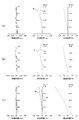
- the figure which shows the various values of the lens system shown in FIG. FIG. 2 shows various aberrations of the lens system shown in FIG. 1
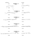
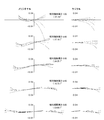
- FIG. 2 is a diagram showing lateral aberration of the lens system shown in FIG. 1 at infinity.
- FIG. 7 shows transverse aberration at an intermediate distance of the lens system shown in FIG. 1;
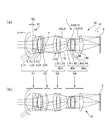
- FIG. 1 shows the state of the focus of a lens system at infinity
- FIG.1 (b) shows the state of a focus at short distance.
- FIG. 6 is a view showing data of each lens of the lens system shown in FIG. 1
- FIG. 7 is a diagram showing aspheric surface data of the lens system shown in FIG. 1.
- FIG. 2 shows various aberrations of the lens system shown in FIG. 1
- FIG. 10 is a view showing data of each lens of the lens system shown in FIG. 9;
- FIG. 10 shows aspheric surface data of the lens system shown in FIG. 9;
- FIG. 10 shows various values of the lens system shown in FIG. 9;
- FIG. 10 shows various aberrations of the lens system shown in FIG. 9;
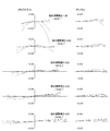
- FIG. 10 shows transverse aberration of the lens system shown in FIG. 9 at infinity.
- FIG. 10 shows transverse aberration at an intermediate distance of the lens system shown in FIG. 9;
- FIG. 10 shows transverse aberration at the shortest distance of the lens system shown in FIG. 9;
- FIG. 17A is a view showing still another example of the lens system and the imaging device,
- FIG. 17A shows a state in which the focus of the lens system is infinity, and
- FIG. 17B shows a state in which the focus is near distance.
- FIG. 18 is a view showing data of each lens of the lens system shown in FIG. 17;
- FIG. 18 shows aspheric surface data of the lens system shown in FIG. 17;
- FIG. 18 shows various values of the lens system shown in FIG. 17;
- FIG. 18 shows various aberrations of the lens system shown in FIG. 17;
- FIG. 18 shows various aberrations of the lens system shown in FIG. 17;
- FIG. 18 shows transverse aberration of the lens system shown in FIG. 17 at infinity.
- FIG. 18 shows transverse aberration at an intermediate distance of the lens system shown in FIG. 17;
- FIG. 18 shows transverse aberration at the shortest distance of the lens system shown in FIG. 17;
- FIG. 1 shows an example of an imaging apparatus (camera, camera apparatus) provided with an optical system for imaging.
- FIG. 1 (a) shows a state in which focusing is at infinity
- FIG. 1 (b) shows a state in which focusing is at a closest distance.
- the camera (imaging device) 1 is disposed on a lens system (optical system, imaging optical system, imaging optical system) 10 and an image plane side (image side, imaging side, imaging side) 12 of the lens system 10 And an imaging device (imaging device, image plane) 5.
- the lens system 10 for imaging includes a first lens unit G1 of negative refractive power fixed during focusing, and a positive refractive power that moves during focusing, disposed in order from the object side 11 And a second lens group G2 of the second lens group G2, a third lens group G3 of positive refractive power fixed during focusing, and an aperture stop St disposed on the object side 11 and fixed during focusing Is composed of a positive fourth lens group G4.
- This lens system 10 is a negative-positive-positive-positive four-group retrofocus type, and is an inner-focus type in which only the second lens group G2 moves along the optical axis 7 during focusing. It is a lens system in which a diaphragm St is disposed between the fixed third lens group G3 and the fourth lens group G4.
- a retrofocus type in which the lens group G1 on the most object side 11 has a negative power is suitable for a wide-angle lens, but in general when a positive power lens is in focus in an inner focus type because the positive power of the rear group is strong. The magnification is likely to change if it moves.
- the rear group of positive power is divided into three groups to disperse the power, the power of the second lens group G2 that moves during focusing is suppressed, and the focusing is performed. Even if the second lens group G2 moves, the magnification does not easily change. Furthermore, by disposing the diaphragm St between the third lens group G3 and the fourth lens group G4 which do not move (fixed) during focusing, it is possible to prevent the F value from being changed by focusing. There is. For this reason, it is possible to provide a lens system capable of freely adjusting the focus with little consideration to fluctuations in magnification and fluctuations in brightness.
- the second lens group G2 includes, on the object side 11, one lens L21 having a concave meniscus type positive refractive power.
- This lens L21 may be replaced by a cemented lens.
- the second lens group G2 is a one-lens configuration of the meniscus lens L21, and moves during focusing, and the first lens group G1 of negative power
- the lens L21 of the second lens group G2 closest to the lens group G2 is a lens of positive meniscus type positive refractive power concave on the object side 11.
- the retrofocus type has a positive refractive power and is likely to increase the Petzval sum.
- the lens system 10 which can correct aberration correction, in particular, spherical aberration and coma aberration well.
- the second lens group G2 specifically the lens L21
- the lens L21 is focused.
- the light can be captured by the second lens group G2 including ambient light and transmitted to the lens group on the image plane side 12. For this reason, it is possible to provide a brighter lens system 10 with a small F value.
- the second lens group of positive power close to the first lens group G1 of negative power, it is possible to suppress the spread of the light flux, and the third lens group G3 and subsequent ones on the image plane side.
- the size can be reduced, and a more compact lens system 10 can be provided.
- the combined focal length G1f of the first lens group and the combined focal length G2f of the second lens group satisfy the following conditions. ⁇ 0.3 ⁇ G 1 f / G 2 f ⁇ 0 (1)
- the power of the second lens group G2 to be moved during focusing is controlled within the range of the above condition (1) by making the rear group of positive power of retrofocus type into a three-group configuration, and the magnification during focusing
- the fluctuation can be suppressed, and the fluctuation of the angle of view can also be suppressed.
- the fluctuation of the F-number at the time of focusing is also suppressed. Therefore, it is possible to provide the imaging device (camera) 1 in which the variation of the brightness, the magnification, and the angle of view due to focusing is small and the focusing can be easily adjusted freely in shooting a video or a movie.
- the first lens group G1 includes a first negative meniscus lens L11 convex to the object side 11 disposed closest to the object side 11, a negative biconcave negative lens L12, and a second negative negative convex to the object side 11. And the meniscus lens L13.
- a configuration in which the negative meniscus lens L11 convex on the object side 11 is disposed closest to the object side 11 and the negative meniscus lens L13 convex similarly on the object side 11 on the image plane side 12 is wide It is suitable for the lens system 10 which obtains a bright image at the corner.
- the convex surface overlaps the object side 11 the Petzval sum is likely to increase and the aberration correction becomes difficult.
- a biconcave negative lens may be disposed adjacent to a configuration in which a convex negative meniscus lens is adjacent to the object side 11. That is, the second meniscus lens L13 and the biconcave negative lens L12 may be disposed adjacent to each other so that one of them is on the object side 11, and the effect of suppressing the increase in Petzval sum can be achieved. Is obtained.
- a negative meniscus lens convex on the object side 11 (first meniscus lens) L11, a biconcave negative lens L12, a negative meniscus lens convex on the object side 11 (second).
- the combination of a meniscus lens L13 is a combination of negative power lenses, but correction of on-axis chromatic aberration is effectively performed because the curvature directions of the adjacent surfaces of the two lenses L11 and L12 on the object side 11 are different. It is possible to further reduce the difference between the sagittal image plane and the median image plane.
- the surface on the object side 11 of the negative lens L12 (surface concave on the object side) is the surface on the image plane side 12 of the other lens disposed on the object side 11 of that surface (convex surface on the object side).
- the first meniscus lens L11, the negative lens L12 and the second meniscus lens L13 it is desirable that they be disposed as close as possible.
- the distance between the surface on the image side 12 of the first meniscus lens L11 on the object side 11 and the surface on the object side 11 of the negative lens L12 is the surface on the image side 12 of the negative lens L12. It is desirable that the distance from the object side surface of the second meniscus lens L13 be short and close.
- the first meniscus lens L11 or the second meniscus lens L13 (in this example, the first meniscus lens L11 disposed in the end portion of the surface of the negative lens L12 on the object side 11 and the object side 11 of the negative lens L12).
- a first distance E1 along the optical axis from the end of the surface on the image plane side 12 of the lens L11), an end of the surface on the object side 11 of the second meniscus lens L13, and the second meniscus lens L13 The end of the surface on the image plane side 12 of the first meniscus lens L11 or negative lens L12 (in this example, the negative lens L12) disposed on the object side 11 and the second distance E2 along the optical axis are It is desirable to satisfy the condition.
- the first distance E1 is positioned such that the minimum air gap or lens edge (edge) contacts, and the first distance E1 is the minimum air gap or zero.
- the third lens group G3 is composed of, in order from the object side 11, a lens L31 of positive refractive power, and a cemented lens B31 of positive refractive power, which is composed of a lens L32 of positive refractive power and a lens L33 of negative refractive power. Including.
- strong positive power is disposed in the rear group, but the chromatic aberration can be improved by providing a cemented lens B31 of positive refractive power in the third lens group.
- by arranging the positive lens L31 on the object side 11 and arranging the positive lenses L31 and L32 from the object side 11 it is possible to disperse the surface of positive power, and the light flux is bent sharply. Can be suppressed. Therefore, this configuration is suitable for the improvement of spherical aberration.
- the surface G3LS on the image plane side 12 of the cemented lens B31 of the third lens group G3 (S17 in the surface shown in FIG. 2 below) is adjacent to the stop St, and the effective radius G3LSH of that surface, the curvature radius G3LSr, and The hemispheric rate which is the ratio of may satisfy the following condition (3). 0 ⁇
- the surface G3LS on the object side 11 of the stop St By setting the surface G3LS on the object side 11 of the stop St to a plane close to a plane that satisfies the above condition (3), it is possible to suppress the dispersion of light flux in the surface immediately before the stop St. Therefore, it is possible to obtain a bright lens system 10 with small coma.
- the third lens group G3 is a combination of the positive lens L31 and the positive cemented lens B31 to the object side
- the positive power can be dispersed to the 11th surface to obtain a predetermined power as the third lens group G3.
- the upper limit of the condition (3) may be 0.1, or may be 0.06.
- the fourth lens group G4 includes, in order from the object side 11, a first cemented (first cemented lens) lens B41 consisting of a lens L41 of negative refractive power and a lens L42 of positive refractive power; It includes a second cemented lens (next cemented lens) B42 consisting of a lens L43 and a lens L44 of positive refractive power, a negative meniscus lens L45 concave on the object side, and a lens L46 of positive refractive power.
- first cemented (first cemented lens) lens B41 consisting of a lens L41 of negative refractive power and a lens L42 of positive refractive power
- It includes a second cemented lens (next cemented lens) B42 consisting of a lens L43 and a lens L44 of positive refractive power, a negative meniscus lens L45 concave on the object side, and a lens L46 of positive refractive power.
- this fourth lens group G4 a combination of negative-positive-negative-positive-negative-positive lenses from the object side 11 as a whole makes it easy to correct axial chromatic aberration, and further, the two image plane sides 12 are independent By forming the lens as described above, an independent surface is provided, and correction of other aberrations, including lateral chromatic aberration, can be easily performed.
- the fourth lens group G4 has a negative-positive (junction lens B41) symmetry. Power arrangement is employed, and aberration correction is good. That is, the third lens group G3 includes a cemented lens B31, which is disposed adjacent to the aperture stop St, from the object side 11 to the lens L32 of positive refractive power and the lens L33 of negative refractive power.
- the configuration including the cemented lens B41 in which the lens group G4 is disposed adjacent to the diaphragm St and includes the lens L41 having negative refractive power from the object side 11 and the lens L42 having positive refractive power is symmetrical about the diaphragm St. It is a configuration with high quality, and a configuration in which aberrations are easily corrected well.
- the third lens group G3 includes the lens L31 having positive power from the object side 11 and the positive-negative cemented lens B31, and the fourth lens group G4 has the diaphragm St interposed therebetween. From the object side 11, it includes negative-positive cemented lenses B41 and B42, a lens L45 of negative power and a lens L46 of positive power. Therefore, the lens arrangement of the third lens group G3 and the fourth lens group G4 arranged with the stop St in between has high power symmetry, and is configured to be suitable for aberration correction.
- a hemispherical rate which is a ratio of the effective radius G4B1SH of the surface G4B1S (S21 in the surface shown in FIG. 2 below) of the first cemented lens B41 of the fourth lens group G4 to the radius of curvature G4B1Sr May satisfy the following condition (4).
- This surface G4B1S is the surface on the image plane side 12 of the aperture stop St closest to the aperture stop St, and a certain degree of curvature is necessary for aberration correction, but it is difficult to correct the aberration if the curvature increases become. Therefore, the range of the condition (4) is suitable for the correction of coma and lateral chromatic aberration.
- the lower limit of the condition (4) may be 0.001 or 0.1.
- the upper limit of the condition (4) may be 0.25 or 0.2.
- the cemented surfaces of the cemented lenses B41 and B42 of the fourth lens group G4 are preferably both convex on the object side 11, and the cemented surface of the cemented lens B31 of the third lens group G3 (concave to the object side 11) It is desirable to be symmetrical.
- the cemented surface is arranged symmetrically with respect to the aperture stop St, which is a configuration suitable for aberration correction.
- the hemispherical rate which is the ratio of may satisfy the following condition (5). 0 ⁇
- the positive power lens L46 on the most image plane side 12 of the fourth lens group G4 is an imaging lens on the most image plane side 12 of the lens system 10, and the light flux dispersed by the lens on the object side 11 therefrom is It functions to collect light.
- a lens L46 close to plano-convex is more suitable for the final aberration correction than a biconvex positive lens in which both surfaces are convex and aberrations are apt to occur.
- the upper limit of the condition (5) may be 0.1 or 0.05.
- FIG. 1A shows a lens arrangement in which the focus position is at infinity
- FIG. 1B shows a lens arrangement in the shortest focus position (close distance, 145 mm).
- the lens system 10 is a wide-angle lens having a focal length of 29 mm at infinity, and is configured as an interchangeable lens of a camera 1 for photographing a movie or a video.
- the lens system 10 has a four-group configuration, and from the object side 11, a first lens group G1 having a negative combined refractive power (power), a second lens group G2 having a positive power, and a third lens group having a positive power
- the first lens group G1, the third lens group G3 and the fourth lens group G4 are composed of the third lens group G4 having a positive power G3, the diaphragm St, and the positive power, and the distance to the image plane 5 remains unchanged during focusing. It is a fixed lens group that does not move.
- the second lens group G2 moves monotonously to the image plane side 12 when the focus position moves from infinity to a short distance during focusing.
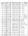
- the data of each lens which comprises the lens system 10 in FIG. 2 are shown.
- the radius of curvature (Ri) is the radius of curvature (mm) of each surface of each lens arranged in order from the object side 11, the distance di is the distance between each lens surface (mm), and the effective diameter (Di) is the effective of each lens surface
- the diameter (diameter, mm) and the refractive index nd indicate the refractive index (d-line) of each lens, and the Abbe number dd indicates the Abbe number (d-line) of each lens.
- the surface having an asterisk appended to the surface number is aspheric, and the one having an asterisk appended to the lens name indicates that it is a lens using anomalous dispersion glass. The same applies to the following.
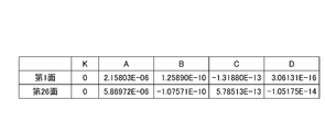
- FIG. 3 shows the coefficients of the aspheric surface included in the lens system 10.
- the surface S1 of the object side 11 of the lens L11 on the most object side 11 of the first lens group G1 and the surface S26 of the image plane side of the lens L45 of the fourth lens group G4 are aspheric.
- the aspheric surface be an internal surface of the lens system 10.
- the surface S1 on the object side 11 of the lens L11 on the most object side 11 has the largest effective diameter, and the effect of asphericizing is large. Therefore, it is suitable for stable and good aberration correction.
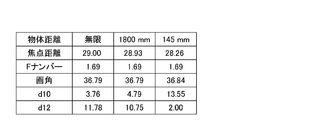
- the focal length f of the lens system 10 when the focal length of the lens system 10 is infinity, middle (1800 mm), shortest (closest, 145 mm), F number (F No.), angle of view, variable spacing The values of d10 and d12 are shown.
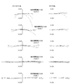
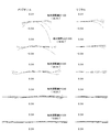
- the focal length of the lens system 10 is infinite (FIG. 5 (a)), middle (1800 mm) (FIG. 5 (b)), shortest (closest, 145 mm) (FIG. 5 (c)) It shows spherical aberration, astigmatism and distortion. Also, FIG. 6 shows the transverse aberration at infinity, FIG. 7 shows the transverse aberration at the middle (1800 mm), and FIG. 8 shows the transverse aberration at the shortest (closest, 145 mm) .
- the spherical aberration has a wavelength of 404.6560 nm (dot and dash line), a wavelength of 435.8340 nm (dotted line), a wavelength of 486.1330 nm (dot and short dashed line), a wavelength of 546.0740 nm (dot and dash line), and a wavelength of 587.5620 nm. (Short dashed dotted line) and wavelength 656.2720 nm (solid line) are shown. Astigmatism indicates a meridional (tangential) ray M and a sagittal ray Sa. The same applies to the aberration diagrams shown below.
- the lens system 10 shown in these figures consists of 15 lenses (L11 to L15, L21, L31 to L33, L41 to L46) in total.
- the first lens group G1 disposed closest to the object side 11 is a biconvex negative meniscus lens (first meniscus lens) L11 disposed on the object side 11, which is disposed from the object side 11.
- the second lens group G2 which is a focusing lens group, has a single lens configuration of a positive meniscus lens L21 concave on the object side 11.
- the third lens group G3 is composed of, in order from the object side 11, a double convex positive lens L31, and a cemented lens B31 consisting of a double convex positive lens L32 and a negative meniscus lens L33 concave on the object side 11. It is configured.
- the fourth lens group G4 located on the image plane side 12 with respect to the third lens group G3 with the stop St interposed therebetween and disposed closest to the image plane side 12 is a biconcave negative lens L41 and the object side 11
- the lens system 10 shown in FIG. 1 includes all the configurations described above, and the values of the respective conditions are as follows.
- Condition (5) (
- the lens system 10 shown in FIG. 1 satisfies all of the conditions (1) to (5), has a focal length of 29 mm, an angle of view of 36.8 degrees, and an F number of 1.69. Bright lens system. Furthermore, in this lens system 10, the F number is fixed during focusing from infinity to near distance, the focal length and the angle of view hardly change, magnification variation hardly occurs, focusing is easy, sharp, or desired By focusing, it is possible to acquire an image with less variation in brightness. Further, as shown in FIG. 5 to FIG. 8, it is possible to acquire an image in which various aberrations are well corrected over the entire area of focusing.
- FIG. 9 (a) shows a lens arrangement in which the focus position is at infinity
- FIG. 9 (b) shows a lens arrangement in the shortest focus position (short distance, 150 mm).
- This lens system 10 is also configured entirely of 15 lenses (L11 to L15, L21, L31 to L33, L41 to L46), and arranged in order from the object side 11, negative refractive power fixed during focusing
- a stop St is disposed on the object side 11, and is configured of a fourth lens group G4 having a positive refractive power, which is fixed during focusing.
- this lens system 10 is also a retrofocus type of negative-positive-positive-positive 4-group configuration, and is an inner focus type in which only the second lens group G2 moves along the optical axis 7 during focusing. And a lens system in which a diaphragm St is disposed between the fixed third lens group G3 and the fourth lens group G4.
- the second lens group G2 is a single-lens configuration of a positive meniscus lens L21 concave on the object side 11, and simply moves from the object side 11 to the image plane side 12 when focusing from infinity to a short distance.
- FIG. 10 data of each lens constituting the lens system 10 is shown.
- FIG. 11 shows the coefficients of the aspheric surface included in the lens system 10
- FIG. 12 shows the lens system 10 when the focal length of the lens system 10 is infinite, intermediate (1800 mm), shortest (closest, 150 mm).
- the values of focal length f, F number (FNo.), Angle of view, and variable intervals d10 and d12 are shown.
- the focal length of the lens system 10 is infinite (FIG. 13 (a)), middle (1800 mm) (FIG. 13 (b)), shortest (closest, 150 mm) (FIG. 13 (c))
- FIGS. 14 to 16 show lateral aberrations at infinity, in the middle (1800 mm), and at the shortest distance (closest, 150 mm).
- the first lens group G1 closest to the object side is convex from the object side 11 to a meniscus lens (first meniscus lens) L11 of negative power convex on the object side 11 and to the object side 11
- the second meniscus lens and the negative lens are replaced, and the first distance E1 is the end of the surface of the second meniscus lens L12 on the image plane side 12 and the surface of the negative lens L13 on the object side.
- the second distance E2 is the end of the surface on the image plane side 12 of the first meniscus lens L11 and the surface of the object side 11 of the second meniscus lens L12.
- the distance to the end of the The configuration of the other first lens group G1 and the configurations of the other lens groups G2 to G4 are the same as those of the lens system 10 shown in FIG.
- Condition (1) (G1f / G2f): -0.136
- Condition (3) (
- Condition (4) (
- Condition (5) (
- the lens system 10 shown in FIG. 9 also satisfies all of the conditions (1) to (5), has a focal length of 29 mm, an angle of view of 36.8 degrees, and an F number of 1.68. Bright lens system. Furthermore, in this lens system 10, the F number is fixed during focusing from infinity to near distance, the focal length and the angle of view hardly change, and there is no change in magnification, and focusing is easy, sharp or desired. By focusing, it is possible to acquire an image with less variation in brightness. Further, as shown in FIG. 13 to FIG. 16, it is possible to acquire an image in which various aberrations are favorably corrected over the entire area of focusing.
- FIG. 17 (a) shows a lens arrangement in which the focus position is at infinity
- FIG. 17 (b) shows a lens arrangement in the shortest focus position (short distance, 190 mm).
- This lens system 10 is also configured entirely of 15 lenses (L11 to L15, L21, L31 to L33, L41 to L46), and arranged in order from the object side 11, negative refractive power fixed during focusing
- a stop St is disposed on the object side 11, and is configured of a fourth lens group G4 having a positive refractive power, which is fixed during focusing.
- this lens system 10 is also a retrofocus type of negative-positive-positive-positive 4-group configuration, and is an inner focus type in which only the second lens group G2 moves along the optical axis 7 during focusing. And a lens system in which a diaphragm St is disposed between the fixed third lens group G3 and the fourth lens group G4.
- the second lens group G2 is a single-lens configuration of a positive meniscus lens L21 concave on the object side 11, and simply moves from the object side 11 to the image plane side 12 when focusing from infinity to a short distance.
- FIG. 19 shows the coefficients of the aspheric surface included in the lens system 10
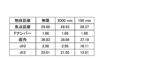
- FIG. 20 shows the lens system 10 when the focal length of the lens system 10 is infinite, intermediate (2000 mm) and shortest (closest, 190 mm).
- the values of focal length f, F number (FNo.), Angle of view, and variable intervals d10 and d12 are shown.
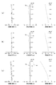
- the focal length of the lens system 10 is infinite (FIG. 21 (a)), middle (2000 mm) (FIG. 21 (b)), shortest (closest, 190 mm) (FIG. 21 (c)). It shows spherical aberration, astigmatism and distortion when.
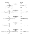
- FIGS. 22-24 show lateral aberrations at infinity, in the middle (2000 mm), and at the shortest (closest, 190 mm).
- the first lens group G1 closest to the object side is common to the lens system 10 shown in FIG. 9, and the configuration of the other first lens group G1 and the configuration of the other lens groups G2 to G4 Is common to the lens system 10 shown in FIG.
- Condition (1) (G1f / G2f): -0.14 Condition (2) (E1 ⁇ E2): (0.40 / 4.97) Condition (3) (
- Condition (4) (
- Condition (5) (
- the lens system 10 shown in FIG. 17 satisfies the conditions (1) to (3) and (5), and the surface S21 on the image plane side 12 of the cemented lens B41 is too close to a plane for the condition (4).
- the aberration correction ability tends to be slightly lacking.
- aberrations such as coma aberration are corrected to a good range by arranging more anomalous dispersive lenses in both of the lenses constituting the cemented lens B 42 and the like and by arranging more at major locations.
- the lens system 10 also has a focal length of 29 mm, a wide angle of view of 36.8 degrees, and a very bright lens system with an F number of 1.66.
- the F number is fixed during focusing from infinity to near distance, the focal length and the angle of view hardly change, magnification variation hardly occurs, focusing is easy, sharp, or desired
- focusing it is possible to acquire an image with less variation in brightness.
- FIGS. 21 to 25 it is possible to acquire an image in which various aberrations are favorably corrected over the entire area of focusing.
Landscapes
- Physics & Mathematics (AREA)
- General Physics & Mathematics (AREA)
- Optics & Photonics (AREA)
- Nonlinear Science (AREA)
- Lenses (AREA)
Abstract
撮像用のレンズシステム(10)は、物体側(11)から順番に配置された、フォーカシングの際に固定された負の屈折力の第1のレンズ群(G1)と、フォーカシングの際に移動する、正の屈折力の第2のレンズ群(G2)と、フォーカシングの際に固定された、正の屈折力の第3のレンズ群(G3)と、物体側に絞りが配置され、フォーカシングの際に固定され、最も像面側に配置された屈折力が正の第4のレンズ群(G4)とを有する。第2のレンズ群は、物体側に凹のメニスカスタイプの正の屈折力の1枚のレンズ(L21)または接合レンズを含んでもよい。
Description
本発明は、レンズシステムおよび撮像装置に関するものである。
日本国特許公開公報2001-228391号には、3群構成のレトロフォーカスタイプのインナーフォーカス式広角レンズ系であって、半画角44゜程度、Fナンバー3.5程度の広角レンズ系が開示されている。この広角レンズ系は、物体側から順に、負の第1レンズ群と、正の第2レンズ群と、絞りを有する正の第3レンズ群とからなり、フォーカシングに際し、第2レンズ群が光軸方向に移動する。
さらに明るく、フォーカシングによる倍率変動が小さい撮像系が求められている。
本発明の一態様は撮像用のレンズシステムであって、物体側から順番に配置された、フォーカシングの際に固定された負の屈折力の第1のレンズ群と、フォーカシングの際に移動する、正の屈折力の第2のレンズ群と、フォーカシングの際に固定された、正の屈折力の第3のレンズ群と、物体側に絞りが配置され、フォーカシングの際に固定され、最も像面側に配置された屈折力が正の第4のレンズ群とを有するレンズシステムである。
このレンズシステムは、負-正-正-正の4群構成のレトロフォーカスタイプで、第2のレンズ群のみがフォーカシングの際に光軸に沿って移動するインナーフォーカス式であり、さらに、固定された第3のレンズ群と第4のレンズ群との間に絞りが配置されているレンズシステムである。最も物体側のレンズ群が負のパワーのレトロフォーカスタイプは広角レンズに適しているが正のパワーが強いためにインナーフォーカスタイプで正のパワーのレンズがフォーカスの際に移動すると倍率が変化しやすい。このため、このレンズシステムにおいては、正のパワーの後群を3群構成に分けてパワーを分散し、フォーカシングの際に移動する第2のレンズ群のパワーを抑制し、フォーカシングの際に第2のレンズ群が移動しても倍率が変動しにくい構成としている。さらに、フォーカシングの際に動かない(固定されている)第3のレンズ群と第4のレンズ群との間に絞りを配置することによりフォーカシングによりF値が変動することを防止している。このため、倍率が変動や、明るさの変動をほとんど考慮することなく、フォーカスを自由に調整できるレンズシステムを提供できる。
さらに、第2のレンズ群は、物体側に凹のメニスカスタイプの正の屈折力の1枚のレンズまたは接合レンズを含んでもよい。フォーカシングの際に移動し、負のパワーの第1のレンズ群に最も近い第2のレンズ群に物体側に凹のメニスカスタイプの正の屈折力の1枚または接合レンズを含めてもよい。レトロフォーカスタイプは正の屈折力が強くなりペッツバール和が増大しやすい。このレンズシステムにおいては、正の屈折力の後群の最も物体側となる第2のレンズ群に、物体側に凹の面を配置することによりペッツバール和の増大を抑制して、収差補正がより良好なレンズシステムを提供している。さらに、物体側の第1のレンズ群に向いた面を物体側に凹の面とすることによりフォーカシングの際に動く第2のレンズ群を、特にレンズの周辺部分を、負のパワーの第1のレンズ群に近づけることが可能となり、周辺光を含めて第2のレンズ群により像面側のレンズ群に伝達しやすい。このため、より明るく、F値の小さなレンズシステムを提供できる。また、負のパワーの第1のレンズ群に接近して正のパワーの第2のレンズ群を配置することにより、光束の広がりを抑制でき、像面側の第3のレンズ群以降のサイズを抑制でき、よりコンパクトなレンズシステムを提供できる。
第3のレンズ群は、絞りに隣接して配置された、物体側から正の屈折力のレンズおよび負の屈折力のレンズからなる接合レンズを含み、第4のレンズ群は、絞りに隣接して配置された、物体側から負の屈折力のレンズおよび正の屈折力のレンズからなる接合レンズ(最初の接合レンズ、第1の接合レンズ)を含んでもよい。
第3のレンズ群に絞りに隣接して、物体側から正の屈折力のレンズおよび負の屈折力のレンズからなる接合レンズを配置し、第4のレンズ群に、絞りに隣接して、物体側から負の屈折力のレンズおよび正の屈折力のレンズからなる接合レンズを配置し、絞りに対して接合レンズをパワー配分が対称になる配置を採用している。したがって、諸収差の補正が良好なレンズシステムを提供できる。
本発明の他の態様の1つは、上記のレンズシステムと、レンズシステムの像面側に配置された撮像素子とを有する撮像装置である。
図1に、撮像用の光学系を備えた撮像装置(カメラ、カメラ装置)の一例を示している。図1(a)はフォーカシングが無限遠の状態を示し、図1(b)はフォーカシングが最近距離の状態を示す。このカメラ(撮像装置)1は、レンズシステム(光学系、撮像光学系、結像光学系)10と、レンズシステム10の像面側(画像側、撮像側、結像側)12に配置された撮像素子(撮像デバイス、像面)5とを有する。この撮像用のレンズシステム10は、物体側11から順番に配置された、フォーカシングの際に固定された負の屈折力の第1のレンズ群G1と、フォーカシングの際に移動する、正の屈折力の第2のレンズ群G2と、フォーカシングの際に固定された、正の屈折力の第3のレンズ群G3と、物体側11に絞りStが配置され、フォーカシングの際に固定された、屈折力が正の第4のレンズ群G4とから構成されている。
このレンズシステム10は、負-正-正-正の4群構成のレトロフォーカスタイプで、第2のレンズ群G2のみがフォーカシングの際に光軸7に沿って移動するインナーフォーカス式であり、さらに、固定された第3のレンズ群G3と第4のレンズ群G4との間に絞りStが配置されているレンズシステムである。最も物体側11のレンズ群G1が負のパワーのレトロフォーカスタイプは広角レンズに適しているが、一般に後群の正のパワーが強いためにインナーフォーカスタイプで正のパワーのレンズがフォーカスの際に移動すると倍率が変化しやすい。このため、このレンズシステム10においては、正のパワーの後群を3群構成に分けてパワーを分散し、フォーカシングの際に移動する第2のレンズ群G2のパワーを抑制し、フォーカシングの際に第2のレンズ群G2が移動しても倍率が変動しにくい構成としている。さらに、フォーカシングの際に動かない(固定されている)第3のレンズ群G3と第4のレンズ群G4との間に絞りStを配置することによりフォーカシングによりF値が変動することを防止している。このため、倍率が変動や、明るさの変動をほとんど考慮することなく、フォーカスを自由に調整できるレンズシステムを提供できる。
第2のレンズ群G2は、物体側11に凹のメニスカスタイプの正の屈折力の1枚のレンズL21を含む。このレンズL21は接合レンズに置き換えられてもよい、本例では第2のレンズ群G2はメニスカスレンズL21の一枚構成であり、フォーカシングの際に移動し、負のパワーの第1のレンズ群G1に最も近い第2のレンズ群G2のレンズL21が物体側11に凹の正のメニスカスタイプの正の屈折力のレンズとなっている。レトロフォーカスタイプは正の屈折力が強くなりペッツバール和が増大しやすい。このレンズシステム10においては、正の屈折力の後群の最も物体側11となる第2のレンズ群G2のレンズL21に、物体側11に凹の面を配置することによりペッツバール和の増大を抑制して、収差補正、特に、球面収差およびコマ収差を良好に補正できるレンズシステム10を提供している。
さらに、物体側11の第1のレンズ群G1に向いたレンズL21の物体側の面を物体側11に凹の面とすることにより、第2のレンズ群G2、具体的にはレンズL21をフォーカシングの際に第1のレンズ群G1に近づけることが可能となる。すなわち、レンズL21の物体側11に凹面を配置することにより、レンズL21の周辺部分を第1のレンズ群G1に近づけることが可能となり、負のパワーの第1のレンズ群G1で広がりやすい光束を、周辺光を含めて第2のレンズ群G2により捉えて像面側12のレンズ群に伝達できる。このため、より明るく、F値の小さなレンズシステム10を提供できる。また、負のパワーの第1のレンズ群G1に接近して正のパワーの第2のレンズ群を配置することにより、光束の広がりを抑制でき、像面側の第3のレンズ群G3以降のサイズを抑制でき、よりコンパクトなレンズシステム10を提供できる。
第1のレンズ群の合成焦点距離G1fと、第2のレンズ群の合成焦点距離G2fとが以下の条件を満たすことが好ましい。
-0.3≦G1f/G2f<0・・・(1)
-0.3≦G1f/G2f<0・・・(1)
レトロフォーカス式の正のパワーの後群を3群構成にすることによりフォーカシングの際に移動させる第2のレンズ群G2のパワーを上記条件(1)の範囲に抑制することによりフォーカシングの際の倍率変動を抑制でき、さらに画角の変動も抑制できる。また、上述したように、このレンズシステム10においては、フォーカシングの際のF値の変動も抑制されている。したがって、フォーカシングによる明るさ、倍率および画角の変動が少なく、ビデオや映画の撮影においてフォーカシングを自由に調整しやすい撮像装置(カメラ)1を提供できる。
第1のレンズ群G1は、最も物体側11に配置された物体側11に凸の負の第1のメニスカスレンズL11と、両凹の負レンズL12と、物体側11に凸の負の第2のメニスカスレンズL13とを含む。最も物体側11に、物体側11に凸の負のメニスカスレンズL11を配置し、さらに、その像面側12に、同様に物体側11に凸の負のメニスカスレンズL13を配置する構成は広画角で明るい像を得るレンズシステム10に適している。一方、物体側11に凸の面が重複するためにペッツバール和が増大しやすく収差補正が難しくなる。このため、両凹の負レンズL12を中間に配置することにより、物体側11に凹の面を導入することが可能となりペッツバール和の増大を抑制できる。物体側11に凸の負のメニスカスレンズが隣接した構成に両凹の負レンズを隣接して配置してもよい。すなわち、第2のメニスカスレンズL13と両凹の負レンズL12とは、いずれか一方が物体側11になるように隣接して、入れ替わって配置されていてもよく、ペッツバール和の増大を抑制できる効果が得られる。
一方、図1に示したような、物体側11に凸の負のメニスカスレンズ(第1のメニスカスレンズ)L11、両凹の負レンズL12、物体側11に凸の負のメニスカスレンズ(第2のメニスカスレンズ)L13という組み合わせは、負のパワーのレンズの組み合わせであるが、最も物体側11の2枚のレンズL11およびL12の隣接する面の湾曲方向が異なるので軸上色収差の補正を効果的に行うことができ、さらに、サジタル像面とメジリオナル像面との差を小さく抑えることが可能となる。
また、負レンズL12の物体側11の面(物体側に凹の面)は、その面の物体側11に配置される他のレンズの像面側12の面(物体側に凸の面)に、第1のメニスカスレンズL11、負レンズL12および第2のメニスカスレンズL13の組み合わせの中で、できる限り接近して配置されていることが望ましい。本例では、物体側11の第1のメニスカスレンズL11の像面側12の面と、負レンズL12の物体側11の面との距離が、負レンズL12の像面側12の面と、第2のメニスカスレンズL13の物体側の面との距離に対して短く、接近していることが望ましい。負のパワーのレンズ同士の組み合わせで、物体側11に凸の面と凹の面とが向かい合って接近した構成を採用することにより、光束の広がりをそれほど変えずに、それらの向きの異なる2つの面を、光軸からほぼ同じ位置を通過させることができる。広角のレンズシステム10では、物体側11のレンズの曲率が一般的に小さく収差が発生しやすいが、対称な面を向かい合わせて近い曲率の場所を光が通過することにより発生した収差をキャンセル、あるいは抑制できる。この構成は、軸上色収差の補正を効果的に行うために好適であり、サジタル像面とメジリオナル像面との差を小さく抑えることが可能となる。
具体的には、負レンズL12の物体側11の面の端部と負レンズL12の物体側11に配置された第1のメニスカスレンズL11または第2のメニスカスレンズL13(本例では第1のメニスカスレンズL11)の像面側12の面の端部との光軸に沿った第1の距離E1と、第2のメニスカスレンズL13の物体側11の面の端部と第2のメニスカスレンズL13の物体側11に配置された第1のメニスカスレンズL11または負レンズL12(本例では負レンズL12)の像面側12の面の端部と光軸に沿った第2の距離E2とが以下の条件を満たすことが望ましい。
E1<E2・・・(2)
多くのケースでは第1の距離E1が最小空気間隔またはレンズの端部(エッジ)同士が接触するように配置され、第1の距離E1は最小空気間隔または0である。
E1<E2・・・(2)
多くのケースでは第1の距離E1が最小空気間隔またはレンズの端部(エッジ)同士が接触するように配置され、第1の距離E1は最小空気間隔または0である。
第3のレンズ群G3は、物体側11から順に、正の屈折力のレンズL31と、正の屈折力のレンズL32および負の屈折力のレンズL33からなる正の屈折力の接合レンズB31とを含む。レトロフォーカス型の場合、後群に強い正のパワーを配置するが、第3のレンズ群に正の屈折力の接合レンズB31を設けることにより色収差を改善できる。さらに、物体側11に正レンズL31を配置し、物体側11から正レンズL31およびL32が並んだ構成とすることにより、正のパワーの面を分散することが可能となり、光束が急激に曲がることを抑制できる。したがって、この構成は、球面収差の改善に適している。
第3のレンズ群G3の接合レンズB31の像面側12の面G3LS(以下の図2に示す面ではS17)は絞りStに隣接しており、その面の有効半径G3LSHと、曲率半径G3LSrとの比である半球率が以下の条件(3)を満たしてもよい。
0<|G3LSH/G3LSr|≦0.2・・・(3)
非点収差およびコマ収差、特にコマ収差は、絞りStを狭くすることにより改善されるが絞りStを通過する光量が減少するために明るいレンズシステム10を得ることが難しくなる。絞りStの物体側11の面G3LSを上記の条件(3)を満たすような平面に近い面とすることにより、絞りStの直前の面における光束の分散を抑制できる。このため、コマ収差が小さく、明るいレンズシステム10を得ることができる。一方、面G3LSを平面に近くすることによりレンズとしてのパワーは得にくいが、第3のレンズ群G3を上述したように正レンズL31と、正の接合レンズB31との組み合わせにすることにより物体側11の面に正のパワーを分散して第3のレンズ群G3としての所定のパワーを得ることができる。条件(3)の上限は0.1であってもよく、さらに、0.06であってもよい。
0<|G3LSH/G3LSr|≦0.2・・・(3)
非点収差およびコマ収差、特にコマ収差は、絞りStを狭くすることにより改善されるが絞りStを通過する光量が減少するために明るいレンズシステム10を得ることが難しくなる。絞りStの物体側11の面G3LSを上記の条件(3)を満たすような平面に近い面とすることにより、絞りStの直前の面における光束の分散を抑制できる。このため、コマ収差が小さく、明るいレンズシステム10を得ることができる。一方、面G3LSを平面に近くすることによりレンズとしてのパワーは得にくいが、第3のレンズ群G3を上述したように正レンズL31と、正の接合レンズB31との組み合わせにすることにより物体側11の面に正のパワーを分散して第3のレンズ群G3としての所定のパワーを得ることができる。条件(3)の上限は0.1であってもよく、さらに、0.06であってもよい。
第4のレンズ群G4は、物体側11から順に、負の屈折力のレンズL41および正の屈折力のレンズL42からなる第1の接合(最初の接合レンズ)レンズB41と、負の屈折力のレンズL43および正の屈折力のレンズL44からなる第2の接合レンズ(次の接合レンズ)B42と、物体側に凹の負のメニスカスレンズL45と、正の屈折力のレンズL46とを含む。この第4のレンズ群G4においては、全体として物体側11から負-正-負-正-負-正のレンズの組み合わせとなり軸上色収差が補正しやすく、さらに像面側12の2枚を独立したレンズとすることにより独立した面を設け、倍率色収差も含めた他の収差の補正も行いやすい構成となっている。
さらに、絞りStを挟んで向かい合う第3のレンズ群G3が正-負の構成(接合レンズB31)であるのに対し、第4のレンズ群G4は負-正(接合レンズB41)の対称的なパワー配置となっており、収差補正が良好な構成となっている。すなわち、第3のレンズ群G3が、絞りStに隣接して配置された、物体側11から正の屈折力のレンズL32および負の屈折力のレンズL33からなる接合レンズB31を含み、第4のレンズ群G4が、絞りStに隣接して配置された、物体側11から負の屈折力のレンズL41および正の屈折力のレンズL42からなる接合レンズB41を含む構成は、絞りStを挟んで対称性の高い構成であり、収差が良好に補正しやすい構成である。
また、このレンズシステム10においては、第3のレンズ群G3が物体側11から正のパワーのレンズL31および正-負の接合レンズB31を含み、絞りStを挟んで、第4のレンズ群G4は、物体側11から、負-正の接合レンズB41およびB42、負のパワーのレンズL45および正のパワーのレンズL46を含む。したがって、絞りStを挟んで配置された第3のレンズ群G3および第4のレンズ群G4のレンズ配置はパワーの対称性が高く、収差補正に適した構成となっている。
さらに、第4のレンズ群G4の第1の接合レンズB41の像面側12の面G4B1S(以下の図2に示す面ではS21)の有効半径G4B1SHと、曲率半径G4B1Srとの比である半球率が以下の条件(4)を満たしてもよい。
0.005≦|G4B1SH/G4B1Sr|≦0.4・・・(4)
この面G4B1Sは絞りStの像面側12で絞りStに最も隣接する像面側12の面であり、収差補正のためにはある程度の曲率が必要であるが、曲率が大きくなると収差補正が困難になる。したがって、条件(4)の範囲がコマ収差と倍率色収差の補正に適している。条件(4)の下限は0.001であってもよく、0.1であってもよい。条件(4)の上限は、0.25であってもよく、0.2であってもよい。
0.005≦|G4B1SH/G4B1Sr|≦0.4・・・(4)
この面G4B1Sは絞りStの像面側12で絞りStに最も隣接する像面側12の面であり、収差補正のためにはある程度の曲率が必要であるが、曲率が大きくなると収差補正が困難になる。したがって、条件(4)の範囲がコマ収差と倍率色収差の補正に適している。条件(4)の下限は0.001であってもよく、0.1であってもよい。条件(4)の上限は、0.25であってもよく、0.2であってもよい。
第4のレンズ群G4の接合レンズB41およびB42の接合面は、ともに物体側11に凸であることが望ましく、第3のレンズ群G3の接合レンズB31の接合面(物体側11に凹)と対称であることが望ましい。接合面が絞りStに対して対称的な配置となり、収差補正に適した構成である。
さらに、第4のレンズ群G4の最も像面側12の正の屈折力のレンズL46の物体側11の面G4PS(以下の図2に示す面ではS27)の有効半径G4PSHと、曲率半径G4PSrとの比である半球率が以下の条件(5)を満たしてもよい。
0<|G4PSH/G4PSr|≦0.2・・・(5)
第4のレンズ群G4の最も像面側12の正のパワーのレンズL46は、レンズシステム10の最も像面側12の結像レンズであり、それより物体側11のレンズで分散された光束を集光する機能を果たす。第4のレンズ群G4は、物体側11に2つの接合レンズB41およびB42が配置され、それらに続いて負のメニスカスレンズL45が配置されており、それらにより収差が補正された光束を集光して結像するためには両面が凸で収差が発生しやすい両凸の正レンズよりも、平凸に近いレンズL46の方が最終の収差補正に適している。条件(5)の上限は0.1であってもよく、0.05であってもよい。
0<|G4PSH/G4PSr|≦0.2・・・(5)
第4のレンズ群G4の最も像面側12の正のパワーのレンズL46は、レンズシステム10の最も像面側12の結像レンズであり、それより物体側11のレンズで分散された光束を集光する機能を果たす。第4のレンズ群G4は、物体側11に2つの接合レンズB41およびB42が配置され、それらに続いて負のメニスカスレンズL45が配置されており、それらにより収差が補正された光束を集光して結像するためには両面が凸で収差が発生しやすい両凸の正レンズよりも、平凸に近いレンズL46の方が最終の収差補正に適している。条件(5)の上限は0.1であってもよく、0.05であってもよい。
図面を参照してさらに詳しく説明する。図1にレンズシステム10の幾つかの状態におけるレンズ配置を示している。図1(a)は、フォーカス位置が無限遠のレンズ配置を示し、図1(b)は、フォーカス位置が最短(近距離、145mm)におけるレンズ配置を示している。
このレンズシステム10は、無限遠における焦点距離が29mmの広角レンズであり、映画あるいはビデオ撮影用のカメラ1の交換レンズとして適した構成となっている。レンズシステム10は4群構成であり、物体側11から合成屈折力(パワー)が負の第1のレンズ群G1、パワーが正の第2のレンズ群G2、パワーが正の第3のレンズ群G3、絞りStおよびパワーが正の第4のレンズ群G4からなり、第1のレンズ群G1、第3のレンズ群G3および第4のレンズ群G4は、フォーカシングに際して像面5に対する距離は変わらずに動かず、固定されたレンズ群である。第2のレンズ群G2は、フォーカシングの際に、無限遠から近距離にフォーカス位置が移動すると、像面側12に単調に移動する。
図2に、レンズシステム10を構成する各レンズのデータを示している。曲率半径(Ri)は物体側11から順に並んだ各レンズの各面の曲率半径(mm)、間隔diは各レンズ面の間の距離(mm)、有効径(Di)は各レンズ面の有効径(直径、mm)、屈折率ndは各レンズの屈折率(d線)、アッベ数νdは各レンズのアッベ数(d線)を示している。図2において、面番号にアスタリスクが付記されている面は非球面であり、レンズ名称にアスタリスクが付記されているものは異常分散性ガラスを用いたレンズであることを示している。以下においても同様である。
図3には、レンズシステム10に含まれる非球面の係数を示す。この例では、第1のレンズ群G1の最も物体側11のレンズL11の物体側11の面S1と、第4のレンズ群G4のレンズL45の像面側の面S26が非球面となっている。交換レンズであることを考慮した場合、非球面はレンズシステム10の内部の面であることが望ましい。一方、最も物体側11のレンズL11の物体側11の面S1は最も有効径が大きく、非球面化する効果が大きい。したがって、安定して良好に収差補正をするために適している。
非球面は、Xを光軸方向の座標、Yを光軸と垂直方向の座標、光の進行方向を正、Rを近軸曲率半径とすると、図3に示した係数K、A、B、CおよびDを用いて次式(X)で表わされる。以降の実施形態においても同様である。なお、「En」は、「10のn乗」を意味する。
X=(1/R)Y2/[1+{1-(1+K)(1/R)2Y2}1/2]
+AY4+BY6+CY8+DY10・・・(X)
X=(1/R)Y2/[1+{1-(1+K)(1/R)2Y2}1/2]
+AY4+BY6+CY8+DY10・・・(X)
図4に、レンズシステム10の焦点距離が無限遠、中間(1800mm)、最短(最接近、145mm)のときのレンズシステム10の焦点距離fと、Fナンバー(FNo.)、画角、可変間隔d10、d12の値を示している。
図5に、レンズシステム10の焦点距離が無限遠(図5(a))、中間(1800mm)(図5(b))、最短(最接近、145mm)(図5(c))のときの球面収差、非点収差、歪曲収差を示している。また、図6に、無限遠のときの横収差を示し、図7に中間(1800mm)のときの横収差を示し、図8に最短(最接近、145mm)のときの横収差を示している。球面収差は、波長404.6560nm(一点鎖線)と、波長435.8340nm(破線)と、波長486.1330nm(ドット、短破線)と、波長546.0740nm(二点鎖線)と、波長587.5620nm(短一点鎖線)と、波長656.2720nm(実線)とを示している。非点収差は、メリジオナル(タンジェンシャル)光線Mとサジタル光線Saとを示している。以下に示した収差図においても同様である。
これらの図に示したレンズシステム10は、全体が15枚のレンズ(L11~L15、L21、L31~L33、L41~L46)からなる。最も物体側11に配置された第1のレンズ群G1は、物体側11から配置された、物体側11に凸の負のパワーのメニスカスレンズ(第1のメニスカスレンズ)L11と、両凹の負レンズL12と、物体側11に凸の負のパワーのメニスカスレンズ(第2のメニスカスレンズ)L13と、両凸の正レンズL14と、物体側11に凹の負のパワーのメニスカスレンズL15との5枚構成である。
フォーカスレンズ群である第2のレンズ群G2は、物体側11に凹の正のメニスカスレンズL21の一枚構成である。
第3のレンズ群G3は、物体側11から順に配置された、両凸の正レンズL31と、両凸の正レンズL32および物体側11に凹の負のメニスカスレンズL33からなる接合レンズB31とから構成されている。
絞りStを挟んで第3のレンズ群G3に対して像面側12に位置し、最も像面側12に配された第4のレンズ群G4は、両凹の負レンズL41および物体側11の凸の正のメニスカスレンズL42からなる接合レンズB41と、物体側11に凸の負のメニスカスレンズL43および両凸の正レンズL44からなる接合レンズB42と、物体側11に凹の負のメニスカスレンズL45と、物体側11に凹の正のメニスカスレンズL46とから構成されている。
図1に示したレンズシステム10は、上述した構成をすべて含んでおり、各条件の値は以下の通りである。
条件(1) (G1f/G2f) : -0.12
条件(2) (E1<E2) : (0.4/13.9)
条件(3) (|G3LSH/G3LSr|(|D17/2/R17|)) : 0.02
条件(4) (|G4B1SH/G4B1Sr|(|D21/2/R21|)) : 0.121
条件(5) (|G4PSH/G4PSr|(D27/2/R27)) : 0.031
条件(1) (G1f/G2f) : -0.12
条件(2) (E1<E2) : (0.4/13.9)
条件(3) (|G3LSH/G3LSr|(|D17/2/R17|)) : 0.02
条件(4) (|G4B1SH/G4B1Sr|(|D21/2/R21|)) : 0.121
条件(5) (|G4PSH/G4PSr|(D27/2/R27)) : 0.031
図1に示したレンズシステム10は、条件(1)~(5)のすべてを満足しており、焦点距離が29mm、画角が36.8度と広角で、Fナンバーが1.69と非常に明るいレンズシステムとなっている。さらに、このレンズシステム10においては、無限遠から近距離までのフォーカシングの際にFナンバーは固定され、焦点距離、画角もほとんど変わらず倍率変動がほとんどなく、フォーカシングが容易で、鮮明で、あるいは所望のフォーカシングで、明るさの変動が少ない画像を取得できる。また、図5ないし図8に示すように、フォーカシングの全域において諸収差が良好に補正された画像を取得できる。
図9に異なるレンズシステム10を示している。図9(a)は、フォーカス位置が無限遠のレンズ配置を示し、図9(b)は、フォーカス位置が最短(近距離、150mm)におけるレンズ配置を示している。このレンズシステム10も全体がレンズ15枚(L11~L15、L21、L31~L33、L41~L46)の構成で、物体側11から順番に配置された、フォーカシングの際に固定された負の屈折力の第1のレンズ群G1と、フォーカシングの際に移動する、正の屈折力の第2のレンズ群G2と、フォーカシングの際に固定された、正の屈折力の第3のレンズ群G3と、物体側11に絞りStが配置され、フォーカシングの際に固定された、屈折力が正の第4のレンズ群G4とから構成されている。
したがって、このレンズシステム10も、負-正-正-正の4群構成のレトロフォーカスタイプで、第2のレンズ群G2のみがフォーカシングの際に光軸7に沿って移動するインナーフォーカス式であり、さらに、固定された第3のレンズ群G3と第4のレンズ群G4との間に絞りStが配置されているレンズシステムである。第2のレンズ群G2は、物体側11に凹の正のメニスカスレンズL21の一枚構成であり、無限遠から近距離にフォーカスする際に物体側11から像面側12に単純に移動する。
図10に、レンズシステム10を構成する各レンズのデータを示している。図11に、レンズシステム10に含まれる非球面の係数を示し、図12に、レンズシステム10の焦点距離が無限遠、中間(1800mm)、最短(最接近、150mm)のときのレンズシステム10の焦点距離fと、Fナンバー(FNo.)、画角、可変間隔d10、d12の値を示している。また、図13に、レンズシステム10の焦点距離が無限遠(図13(a))、中間(1800mm)(図13(b))、最短(最接近、150mm)(図13(c))のときの球面収差、非点収差、歪曲収差を示している。図14ないし16に、無限遠、中間(1800mm)、および最短(最接近、150mm)のときの横収差を示している。
このレンズシステム10では、最も物体側の第1のレンズ群G1が、物体側11から、物体側11に凸の負のパワーのメニスカスレンズ(第1のメニスカスレンズ)L11と、物体側11に凸の負のパワーのメニスカスレンズ(第2のメニスカスレンズ)L12と、両凹の負レンズL13と、両凸の正レンズL14と、物体側11に凹の負のパワーのメニスカスレンズL15との5枚構成である。第2のメニスカスレンズと負レンズとが入れ替わった構成となっており、第1の距離E1は、第2のメニスカスレンズL12の像面側12の面の端部と負レンズL13の物体側の面の端部との光軸7に沿った距離となり、第2の距離E2は、第1のメニスカスレンズL11の像面側12の面の端部と第2のメニスカスレンズL12の物体側11の面の端部との距離となる。その他の第1のレンズ群G1の構成および他のレンズ群G2~G4の構成は図1に示したレンズシステム10と共通する。
図9に示したレンズシステム10の各条件の値は以下の通りである。
条件(1) (G1f/G2f) : -0.136
条件(2) (E1<E2) : (0.41/7.75)
条件(3) (|G3LSH/G3LSr|(|D17/2/R17|)) : 0.12
条件(4) (|G4B1SH/G4B1Sr|(|D21/2/R21|)) : 0.036
条件(5) (|G4PSH/G4PSr|(D27/2/R27)) : 0.035
条件(1) (G1f/G2f) : -0.136
条件(2) (E1<E2) : (0.41/7.75)
条件(3) (|G3LSH/G3LSr|(|D17/2/R17|)) : 0.12
条件(4) (|G4B1SH/G4B1Sr|(|D21/2/R21|)) : 0.036
条件(5) (|G4PSH/G4PSr|(D27/2/R27)) : 0.035
図9に示したレンズシステム10も、条件(1)~(5)のすべてを満足しており、焦点距離が29mm、画角が36.8度と広角で、Fナンバーが1.68と非常に明るいレンズシステムとなっている。さらに、このレンズシステム10においては、無限遠から近距離までのフォーカシングの際にFナンバーは固定され、焦点距離、画角もほとんど変わらず倍率変動がなく、フォーカシングが容易で、鮮明で、あるいは所望のフォーカシングで、明るさの変動が少ない画像を取得できる。また、図13ないし図16に示すように、フォーカシングの全域において諸収差が良好に補正された画像を取得できる。
図17に、さらに異なるレンズシステム10を示している。図17(a)は、フォーカス位置が無限遠のレンズ配置を示し、図17(b)は、フォーカス位置が最短(近距離、190mm)におけるレンズ配置を示している。このレンズシステム10も全体がレンズ15枚(L11~L15、L21、L31~L33、L41~L46)の構成で、物体側11から順番に配置された、フォーカシングの際に固定された負の屈折力の第1のレンズ群G1と、フォーカシングの際に移動する、正の屈折力の第2のレンズ群G2と、フォーカシングの際に固定された、正の屈折力の第3のレンズ群G3と、物体側11に絞りStが配置され、フォーカシングの際に固定された、屈折力が正の第4のレンズ群G4とから構成されている。
したがって、このレンズシステム10も、負-正-正-正の4群構成のレトロフォーカスタイプで、第2のレンズ群G2のみがフォーカシングの際に光軸7に沿って移動するインナーフォーカス式であり、さらに、固定された第3のレンズ群G3と第4のレンズ群G4との間に絞りStが配置されているレンズシステムである。第2のレンズ群G2は、物体側11に凹の正のメニスカスレンズL21の一枚構成であり、無限遠から近距離にフォーカスする際に物体側11から像面側12に単純に移動する。
図18に、レンズシステム10を構成する各レンズのデータを示している。図19に、レンズシステム10に含まれる非球面の係数を示し、図20に、レンズシステム10の焦点距離が無限遠、中間(2000mm)、最短(最接近、190mm)のときのレンズシステム10の焦点距離fと、Fナンバー(FNo.)、画角、可変間隔d10、d12の値を示している。また、図21に、レンズシステム10の焦点距離が無限遠(図21(a))、中間(2000mm)(図21(b))、最短(最接近、190mm)(図21(c))のときの球面収差、非点収差、歪曲収差を示している。図22ないし24に、無限遠、中間(2000mm)、および最短(最接近、190mm)のときの横収差を示している。
このレンズシステム10では、最も物体側の第1のレンズ群G1が、図9に示したレンズシステム10と共通し、その他の第1のレンズ群G1の構成および他のレンズ群G2~G4の構成は図1に示したレンズシステム10と共通する。
図17に示したレンズシステム10の各条件の値は以下の通りである。
条件(1) (G1f/G2f) : -0.14
条件(2) (E1<E2) : (0.40/4.97)
条件(3) (|G3LSH/G3LSr|(|D17/2/R17|)) : 0.06
条件(4) (|G4B1SH/G4B1Sr|(|D21/2/R21|)) : 0.0054
条件(5) (|G4PSH/G4PSr|(D27/2/R27)) : 0.043
条件(1) (G1f/G2f) : -0.14
条件(2) (E1<E2) : (0.40/4.97)
条件(3) (|G3LSH/G3LSr|(|D17/2/R17|)) : 0.06
条件(4) (|G4B1SH/G4B1Sr|(|D21/2/R21|)) : 0.0054
条件(5) (|G4PSH/G4PSr|(D27/2/R27)) : 0.043
図17に示したレンズシステム10は、条件(1)~(3)および(5)を満足しており、条件(4)については接合レンズB41の像面側12の面S21が平面に近すぎて収差補正の能力が若干不足している傾向にある。しかしながら、異常分散レンズを、接合レンズB42を構成する両方のレンズに採用することなど、主要な箇所にさらに多く配置することによりコマ収差などの収差を良好な範囲まで補正している。このレンズシステム10においても、焦点距離が29mm、画角が36.8度と広角で、Fナンバーが1.66と非常に明るいレンズシステムとなっている。さらに、このレンズシステム10においては、無限遠から近距離までのフォーカシングの際にFナンバーは固定され、焦点距離、画角もほとんど変わらず倍率変動がほとんどなく、フォーカシングが容易で、鮮明で、あるいは所望のフォーカシングで、明るさの変動が少ない画像を取得できる。また、図21ないし図25に示すように、フォーカシングの全域において諸収差が良好に補正された画像を取得できる。
Claims (17)
- 撮像用のレンズシステムであって、
物体側から順番に配置された、フォーカシングの際に固定された負の屈折力の第1のレンズ群と、
フォーカシングの際に移動する、正の屈折力の第2のレンズ群と、
フォーカシングの際に固定された、正の屈折力の第3のレンズ群と、
物体側に絞りが配置され、フォーカシングの際に固定され、最も像面側に配置された屈折力が正の第4のレンズ群とを有するレンズシステム。 - 請求項1において、
前記第2のレンズ群は、物体側に凹のメニスカスタイプの正の屈折力のレンズを含む、レンズシステム。 - 請求項2において、
前記メニスカスタイプの正の屈折力のレンズは、1枚のレンズまたは接合レンズである、レンズシステム。 - 請求項1ないし3のいずれかにおいて、
前記第1のレンズ群の合成焦点距離G1fと、前記第2のレンズ群の合成焦点距離G2fとが以下の条件を満たす、レンズシステム。
-0.3≦G1f/G2f<0 - 請求項1ないし4のいずれかにおいて、
前記第3のレンズ群は、物体側から順に、少なくとも1枚の正の屈折力のレンズと、正の屈折力のレンズおよび負の屈折力のレンズからなる接合レンズとを含む、レンズシステム。 - 請求項5において、
前記第3のレンズ群の前記接合レンズの像面側の面は前記絞りに隣接しており、その面の有効半径G3LSHと、曲率半径G3LSrとが以下の条件を満たす、レンズシステム。
0<|G3LSH/G3LSr|≦0.2 - 請求項1ないし6のいずれかにおいて、
前記第4のレンズ群は、物体側から順に、負の屈折力のレンズおよび正の屈折力のレンズからなる第1の接合レンズと、負の屈折力のレンズおよび正の屈折力のレンズからなる第2の接合レンズと、物体側に凹の負のメニスカスレンズと、正の屈折力のレンズとを含む、レンズシステム。 - 請求項7において、
前記第4のレンズ群の前記第1の接合レンズの像面側の面の有効半径G4B1SHと、曲率半径G4B1Srとが以下の条件を満たす、レンズシステム。
0.005≦|G4B1SH/G4B1Sr|≦0.4 - 請求項7または8において、
前記第4のレンズ群の前記正の屈折力のレンズは物体側の面の有効半径G4PSHと、曲率半径G4PSrとが以下の条件を満たす、レンズシステム。
0<|G4PSH/G4PSr|≦0.2 - 請求項1ないし4のいずれかにおいて、
前記第3のレンズ群は、前記絞りに隣接して配置された、物体側から正の屈折力のレンズおよび負の屈折力のレンズからなる接合レンズを含み、
前記第4のレンズ群は、前記絞りに隣接して配置された、物体側から負の屈折力のレンズおよび正の屈折力のレンズからなる第1の接合レンズを含む、レンズシステム。 - 請求項10において、
前記第3のレンズ群は、物体側から順に、少なくとも1枚の正の屈折力のレンズと、前記接合レンズとを含む、レンズシステム。 - 請求項10または11において、
前記第4のレンズ群は、物体側から順に、前記第1の接合レンズと、負の屈折力のレンズおよび正の屈折力のレンズからなる第2の接合レンズと、物体側に凹の負のメニスカスレンズと、正の屈折力のレンズとを含む、レンズシステム。 - 請求項10ないし12のいずれかにおいて、
前記第3のレンズ群の前記接合レンズの像面側の面の有効半径G3LSHと、曲率半径G3LSrと、前記第4のレンズ群の前記第1の接合レンズの像面側の面の有効半径G4B1SHと、曲率半径G4B1Srとが以下の条件を満たす、レンズシステム。
0<|G3LSH/G3LSr|≦0.2
0.005≦|G4B1SH/G4B1Sr|≦0.4 - 請求項9ないし13のいずれかにおいて、
前記第4のレンズ群の前記第1の接合レンズの前記接合面は物体側に凸の面である、レンズシステム。 - 請求項1ないし14のいずれかにおいて、
前記第1のレンズ群は、最も物体側に配置された物体側に凸の負の第1のメニスカスレンズと、物体側に凸の負の第2のメニスカスレンズと、両凹の負レンズとを含み、前記第2のメニスカスレンズと前記負レンズとは、前記第2のメニスカスレンズまたは前記負レンズが物体側になるように隣接して配置されている、レンズシステム。 - 請求項15において、
前記負レンズの物体側の面の端部と前記負レンズの物体側に配置された前記第1のメニスカスレンズまたは前記第2のメニスカスレンズの像面側の面の端部との光軸に沿った第1の距離E1と、前記第2のメニスカスレンズの物体側の面の端部と前記第2のメニスカスレンズの物体側に配置された前記第1のメニスカスレンズまたは前記負レンズの像面側の面の端部と光軸に沿った第2の距離E2とが以下の条件を満たす、レンズシステム。
E1<E2 - 請求項1ないし16のいずれかに記載のレンズシステムと、
前記レンズシステムの像面側に配置された撮像素子とを有する撮像装置。
Priority Applications (3)
| Application Number | Priority Date | Filing Date | Title |
|---|---|---|---|
| JP2019562096A JP7148154B2 (ja) | 2017-12-28 | 2018-12-26 | レンズシステムおよび撮像装置 |
| US16/955,415 US20210072516A1 (en) | 2017-12-28 | 2018-12-26 | Lens system and image pickup apparatus |
| EP18897714.4A EP3734344A4 (en) | 2017-12-28 | 2018-12-26 | LENS SYSTEM AND IMAGING DEVICE |
Applications Claiming Priority (4)
| Application Number | Priority Date | Filing Date | Title |
|---|---|---|---|
| JP2017-253610 | 2017-12-28 | ||
| JP2017253610 | 2017-12-28 | ||
| JP2017253611 | 2017-12-28 | ||
| JP2017-253611 | 2017-12-28 |
Publications (1)
| Publication Number | Publication Date |
|---|---|
| WO2019131748A1 true WO2019131748A1 (ja) | 2019-07-04 |
Family
ID=67063778
Family Applications (1)
| Application Number | Title | Priority Date | Filing Date |
|---|---|---|---|
| PCT/JP2018/047816 Ceased WO2019131748A1 (ja) | 2017-12-28 | 2018-12-26 | レンズシステムおよび撮像装置 |
Country Status (4)
| Country | Link |
|---|---|
| US (1) | US20210072516A1 (ja) |
| EP (1) | EP3734344A4 (ja) |
| JP (1) | JP7148154B2 (ja) |
| WO (1) | WO2019131748A1 (ja) |
Cited By (3)
| Publication number | Priority date | Publication date | Assignee | Title |
|---|---|---|---|---|
| JP2020129022A (ja) * | 2019-02-07 | 2020-08-27 | 株式会社シグマ | 広角レンズ系 |
| TWI708073B (zh) * | 2019-11-05 | 2020-10-21 | 上暘光學股份有限公司 | 高解析度定焦鏡頭 |
| JP2021184030A (ja) * | 2020-05-21 | 2021-12-02 | キヤノン株式会社 | 単焦点レンズおよび撮像装置 |
Citations (12)
| Publication number | Priority date | Publication date | Assignee | Title |
|---|---|---|---|---|
| JP2000098222A (ja) * | 1998-09-18 | 2000-04-07 | Cosina Co Ltd | 投射レンズ |
| JP2001228391A (ja) | 2000-02-16 | 2001-08-24 | Asahi Optical Co Ltd | 広角レンズ系 |
| JP2003307672A (ja) * | 2002-04-08 | 2003-10-31 | Carl Zeiss:Fa | レンズ装置 |
| JP2010054692A (ja) * | 2008-08-27 | 2010-03-11 | Fujinon Corp | 投影レンズおよびこれを用いた投写型表示装置 |
| JP2010054693A (ja) * | 2008-08-27 | 2010-03-11 | Fujinon Corp | 投影レンズおよびこれを用いた投写型表示装置 |
| JP2010054694A (ja) * | 2008-08-27 | 2010-03-11 | Fujinon Corp | 投影レンズおよびこれを用いた投写型表示装置 |
| JP2010128480A (ja) * | 2008-12-01 | 2010-06-10 | Fujinon Corp | 投写用魚眼レンズおよびこれを用いた投写型表示装置 |
| JP2012118243A (ja) * | 2010-11-30 | 2012-06-21 | Ricoh Opt Ind Co Ltd | 投射用レンズおよび投射型画像表示装置 |
| JP2016038547A (ja) * | 2014-08-11 | 2016-03-22 | 株式会社ニコン | 光学系、該光学系を備えた撮像装置、光学系の製造方法 |
| JP2016184136A (ja) * | 2015-03-27 | 2016-10-20 | 株式会社シグマ | 魚眼レンズ |
| JP2017209154A (ja) * | 2016-05-23 | 2017-11-30 | オリンパス株式会社 | 内視鏡システム |
| JP2017211480A (ja) * | 2016-05-25 | 2017-11-30 | 富士フイルム株式会社 | 結像光学系、投写型表示装置、および、撮像装置 |
Family Cites Families (1)
| Publication number | Priority date | Publication date | Assignee | Title |
|---|---|---|---|---|
| JP4700957B2 (ja) * | 2004-12-02 | 2011-06-15 | 日東光学株式会社 | ズームレンズシステム |
-
2018
- 2018-12-26 EP EP18897714.4A patent/EP3734344A4/en not_active Withdrawn
- 2018-12-26 WO PCT/JP2018/047816 patent/WO2019131748A1/ja not_active Ceased
- 2018-12-26 JP JP2019562096A patent/JP7148154B2/ja active Active
- 2018-12-26 US US16/955,415 patent/US20210072516A1/en not_active Abandoned
Patent Citations (12)
| Publication number | Priority date | Publication date | Assignee | Title |
|---|---|---|---|---|
| JP2000098222A (ja) * | 1998-09-18 | 2000-04-07 | Cosina Co Ltd | 投射レンズ |
| JP2001228391A (ja) | 2000-02-16 | 2001-08-24 | Asahi Optical Co Ltd | 広角レンズ系 |
| JP2003307672A (ja) * | 2002-04-08 | 2003-10-31 | Carl Zeiss:Fa | レンズ装置 |
| JP2010054692A (ja) * | 2008-08-27 | 2010-03-11 | Fujinon Corp | 投影レンズおよびこれを用いた投写型表示装置 |
| JP2010054693A (ja) * | 2008-08-27 | 2010-03-11 | Fujinon Corp | 投影レンズおよびこれを用いた投写型表示装置 |
| JP2010054694A (ja) * | 2008-08-27 | 2010-03-11 | Fujinon Corp | 投影レンズおよびこれを用いた投写型表示装置 |
| JP2010128480A (ja) * | 2008-12-01 | 2010-06-10 | Fujinon Corp | 投写用魚眼レンズおよびこれを用いた投写型表示装置 |
| JP2012118243A (ja) * | 2010-11-30 | 2012-06-21 | Ricoh Opt Ind Co Ltd | 投射用レンズおよび投射型画像表示装置 |
| JP2016038547A (ja) * | 2014-08-11 | 2016-03-22 | 株式会社ニコン | 光学系、該光学系を備えた撮像装置、光学系の製造方法 |
| JP2016184136A (ja) * | 2015-03-27 | 2016-10-20 | 株式会社シグマ | 魚眼レンズ |
| JP2017209154A (ja) * | 2016-05-23 | 2017-11-30 | オリンパス株式会社 | 内視鏡システム |
| JP2017211480A (ja) * | 2016-05-25 | 2017-11-30 | 富士フイルム株式会社 | 結像光学系、投写型表示装置、および、撮像装置 |
Non-Patent Citations (1)
| Title |
|---|
| See also references of EP3734344A4 |
Cited By (5)
| Publication number | Priority date | Publication date | Assignee | Title |
|---|---|---|---|---|
| JP2020129022A (ja) * | 2019-02-07 | 2020-08-27 | 株式会社シグマ | 広角レンズ系 |
| JP7162883B2 (ja) | 2019-02-07 | 2022-10-31 | 株式会社シグマ | 広角レンズ系 |
| TWI708073B (zh) * | 2019-11-05 | 2020-10-21 | 上暘光學股份有限公司 | 高解析度定焦鏡頭 |
| JP2021184030A (ja) * | 2020-05-21 | 2021-12-02 | キヤノン株式会社 | 単焦点レンズおよび撮像装置 |
| JP7608069B2 (ja) | 2020-05-21 | 2025-01-06 | キヤノン株式会社 | 単焦点レンズおよび撮像装置 |
Also Published As
| Publication number | Publication date |
|---|---|
| US20210072516A1 (en) | 2021-03-11 |
| EP3734344A1 (en) | 2020-11-04 |
| JPWO2019131748A1 (ja) | 2020-12-10 |
| JP7148154B2 (ja) | 2022-10-05 |
| EP3734344A4 (en) | 2021-08-18 |
Similar Documents
| Publication | Publication Date | Title |
|---|---|---|
| WO2015146067A1 (ja) | ズームレンズ系、交換レンズ装置、及びカメラシステム | |
| WO2012120875A1 (ja) | 変倍光学系および撮像装置 | |
| JP2004258240A (ja) | 可変焦点距離レンズ系 | |
| CN102289057B (zh) | 变焦镜头及摄像装置 | |
| JP7218920B2 (ja) | レンズシステムおよび撮像装置 | |
| JPH05150161A (ja) | 変倍レンズ | |
| JP2009037036A (ja) | ズームレンズ及びそれを有する撮像装置 | |
| JP7148154B2 (ja) | レンズシステムおよび撮像装置 | |
| WO2019244867A1 (ja) | レンズシステムおよび撮像装置 | |
| JP4817551B2 (ja) | ズームレンズ | |
| JP5841675B2 (ja) | ズームレンズおよび撮像装置 | |
| JPWO2013031180A1 (ja) | ズームレンズおよび撮像装置 | |
| US11378788B2 (en) | Zoom lens system and imaging apparatus | |
| JP2011221554A (ja) | ズームレンズ及びそれを用いたビデオカメラ | |
| JP4585796B2 (ja) | ズームレンズ及びそれを有する撮像装置 | |
| JPWO2013031110A1 (ja) | ズームレンズおよび撮像装置 | |
| JP2020012908A (ja) | ズームレンズ及び撮像装置 | |
| JPH1144846A (ja) | ズ−ムレンズ | |
| JP2005316014A (ja) | 超広角レンズ系 | |
| JPWO2019131750A1 (ja) | レンズシステムおよび撮像装置 | |
| JP2021173954A (ja) | 大口径撮像レンズ | |
| JP2019028172A (ja) | ズームレンズシステムおよび撮像装置 | |
| JP2019028175A (ja) | ズームレンズシステムおよび撮像装置 | |
| JP6944185B2 (ja) | ズームレンズシステムおよび撮像装置 | |
| JP2019028174A (ja) | ズームレンズシステムおよび撮像装置 |
Legal Events
| Date | Code | Title | Description |
|---|---|---|---|
| 121 | Ep: the epo has been informed by wipo that ep was designated in this application |
Ref document number: 18897714 Country of ref document: EP Kind code of ref document: A1 |
|
| ENP | Entry into the national phase |
Ref document number: 2019562096 Country of ref document: JP Kind code of ref document: A |
|
| NENP | Non-entry into the national phase |
Ref country code: DE |
|
| ENP | Entry into the national phase |
Ref document number: 2018897714 Country of ref document: EP Effective date: 20200728 |