WO2019131821A1 - 口紅容器 - Google Patents
口紅容器 Download PDFInfo
- Publication number
- WO2019131821A1 WO2019131821A1 PCT/JP2018/047993 JP2018047993W WO2019131821A1 WO 2019131821 A1 WO2019131821 A1 WO 2019131821A1 JP 2018047993 W JP2018047993 W JP 2018047993W WO 2019131821 A1 WO2019131821 A1 WO 2019131821A1
- Authority
- WO
- WIPO (PCT)
- Prior art keywords
- cylinder
- lipstick
- inner cylinder
- cylindrical body
- container
- Prior art date
- Legal status (The legal status is an assumption and is not a legal conclusion. Google has not performed a legal analysis and makes no representation as to the accuracy of the status listed.)
- Ceased
Links
Images


Classifications
-
- A—HUMAN NECESSITIES
- A45—HAND OR TRAVELLING ARTICLES
- A45D—HAIRDRESSING OR SHAVING EQUIPMENT; EQUIPMENT FOR COSMETICS OR COSMETIC TREATMENTS, e.g. FOR MANICURING OR PEDICURING
- A45D40/00—Casings or accessories specially adapted for storing or handling solid or pasty toiletry or cosmetic substances, e.g. shaving soaps or lipsticks
- A45D40/02—Casings wherein movement of the lipstick or like solid is a sliding movement
-
- A—HUMAN NECESSITIES
- A45—HAND OR TRAVELLING ARTICLES
- A45D—HAIRDRESSING OR SHAVING EQUIPMENT; EQUIPMENT FOR COSMETICS OR COSMETIC TREATMENTS, e.g. FOR MANICURING OR PEDICURING
- A45D40/00—Casings or accessories specially adapted for storing or handling solid or pasty toiletry or cosmetic substances, e.g. shaving soaps or lipsticks
- A45D40/02—Casings wherein movement of the lipstick or like solid is a sliding movement
- A45D40/04—Casings wherein movement of the lipstick or like solid is a sliding movement effected by a screw
-
- A—HUMAN NECESSITIES
- A45—HAND OR TRAVELLING ARTICLES
- A45D—HAIRDRESSING OR SHAVING EQUIPMENT; EQUIPMENT FOR COSMETICS OR COSMETIC TREATMENTS, e.g. FOR MANICURING OR PEDICURING
- A45D40/00—Casings or accessories specially adapted for storing or handling solid or pasty toiletry or cosmetic substances, e.g. shaving soaps or lipsticks
- A45D40/12—Casings with provision for preventing undesired movement of the stick
-
- B—PERFORMING OPERATIONS; TRANSPORTING
- B65—CONVEYING; PACKING; STORING; HANDLING THIN OR FILAMENTARY MATERIAL
- B65D—CONTAINERS FOR STORAGE OR TRANSPORT OF ARTICLES OR MATERIALS, e.g. BAGS, BARRELS, BOTTLES, BOXES, CANS, CARTONS, CRATES, DRUMS, JARS, TANKS, HOPPERS, FORWARDING CONTAINERS; ACCESSORIES, CLOSURES, OR FITTINGS THEREFOR; PACKAGING ELEMENTS; PACKAGES
- B65D83/00—Containers or packages with special means for dispensing contents
- B65D83/76—Containers or packages with special means for dispensing contents for dispensing fluent contents by means of a piston
- B65D83/764—Containers or packages with special means for dispensing contents for dispensing fluent contents by means of a piston the piston cooperating with a screw-thread in the side wall of the container
-
- A—HUMAN NECESSITIES
- A45—HAND OR TRAVELLING ARTICLES
- A45D—HAIRDRESSING OR SHAVING EQUIPMENT; EQUIPMENT FOR COSMETICS OR COSMETIC TREATMENTS, e.g. FOR MANICURING OR PEDICURING
- A45D40/00—Casings or accessories specially adapted for storing or handling solid or pasty toiletry or cosmetic substances, e.g. shaving soaps or lipsticks
- A45D2040/0006—Accessories
-
- A—HUMAN NECESSITIES
- A45—HAND OR TRAVELLING ARTICLES
- A45D—HAIRDRESSING OR SHAVING EQUIPMENT; EQUIPMENT FOR COSMETICS OR COSMETIC TREATMENTS, e.g. FOR MANICURING OR PEDICURING
- A45D40/00—Casings or accessories specially adapted for storing or handling solid or pasty toiletry or cosmetic substances, e.g. shaving soaps or lipsticks
- A45D40/06—Casings wherein movement of the lipstick or like solid is a screwing movement
Definitions
- the present invention relates to a lipstick container for drawing out lipstick by a pivoting operation, and more particularly to a lipstick container for storing lipstick with soft hardness.
- Priority is claimed on Japanese Patent Application No. 2017-250775, filed Dec. 27, 2017, and Japanese Patent Application No. 2018-069860, filed Mar. 30, 2018. And its contents are incorporated herein.
- the cylindrical-shaped delivery container which accommodates rod-shaped cosmetics, such as a lipstick, is known conventionally (for example, refer patent document 1).
- the delivery container includes a container body and a cap attached to the container body, and the container body includes an inner plate body for storing the rod-like cosmetic and an inner cylinder for accommodating the inner plate body so as to be rotatable and vertically movable.
- the inner cylinder is provided with an outer cylinder that vertically moves the inner tray by rotating along the outer peripheral surface of the inner cylinder. In this feeding container, after removing the cap, by rotating the outer cylinder while grasping the inner cylinder, the rod-like cosmetic material is used to move up and down from the inner cylinder by moving the inner plate up and down.
- the delivery container which prevents accidents, such as breakage of rod-shaped cosmetics by having drawn rod-shaped cosmetics (lipstick) more than necessary, is also conventionally known (for example, refer patent document 2).
- this delivery container when the cover (cap) is removed, the combination of the cosmetic pan (inner disc body) and the screw cylinder can be pushed upward by a specified amount by a spring, and the delivery amount of the rod-like cosmetic is determined to an appropriate amount. Can.
- the small amount feeding operation member is provided, when the rod-like cosmetic is consumed, the consumption amount of the rod type cosmetic can be easily replenished by the progressive operation of the small amount feeding operation member.
- the lipstick stored in the delivery container has been advancing in the direction in which the hardness becomes soft. Therefore, in the delivery container described in Patent Document 1 described above, the user may take out the lipstick too much from the container, and the lipstick may be broken from the root. Further, in the delivery container described in Patent Document 2 described above, it is possible to prevent the accident such as breakage of the lipstick by suppressing the disproportionate amount of the initial lipstick so as to make it dispensable more than necessary although it is sufficient for makeup. However, it can not adjust the amount of distraction of the original lipstick.
- An object of the present invention is to solve the above-mentioned problems, and it is an object of the present invention to provide a lipstick container capable of preventing the lipstick from breaking when the user accidentally puts out the lipstick at the start of use.
- a lipstick container provided with a container body and a cap attached to a container body as the 1st mode of the present invention, and a container body stores lipstick and a screwing pin is provided And a helical groove which is screwed with the screwing pin of the inner plate, and is formed along the outer peripheral surface of the inner cylinder.
- An inner cylinder that moves the inner plate up and down by rotating, and an outer cylinder whose inner peripheral surface is screwed to the outer peripheral surface of the inner cylinder, and the inner cylinder rotates by rotating the outer cylinder.
- the working resistance between the outer cylinder and the inner cylinder to be screwed together is determined by the screw groove of the inner disc and the spiral groove of the inner cylinder.
- Adopt means of lipstick container, which is larger than the working resistance between.
- the working resistance between the outer cylinder and the inner cylinder to be screwed together is determined by the screw groove of the inner disc and the spiral groove of the inner cylinder.
- Adopt means of lipstick container, which is smaller than the working resistance between.
- the inner cylindrical body includes a screw portion screwed to the outer cylindrical body, and a lipstick container in which the pitch of the spiral groove is larger than the pitch of the screw.
- the inner cylinder includes a screw portion screwed to the outer cylinder, and a lipstick container in which the pitch of the spiral groove is smaller than the pitch of the screw.
- the inner cylinder is provided at the upper end portion of the spiral groove, in a direction orthogonal to the direction along the central axis of the inner cylinder.
- the inner cylinder includes a screw portion screwed to the outer cylinder, and a lipstick container having an interference projection formed on the screw portion.
- Adopt means of.
- the interference projection employs a means of intermittently forming a lipstick container.
- the interference projection adopts a means of a lipstick container formed in a valve portion which is elastically deformable in the radial direction.
- the lipstick container according to the present invention contains a lipstick and is provided with a middle plate body provided with a screwing pin, a middle cylinder body for guiding the middle plate body so as to be unable to rotate and move vertically, and a screwing pin and screw of the middle plate body.
- a spiral groove is formed, and the inner cylinder moves the inner disc up and down by rotating along the outer peripheral surface of the middle cylinder, and the outer peripheral surface is screwed to the outer peripheral surface of the inner cylindrical body.
- the user can prevent the lipstick from being broken by mistake without accidentally putting out the lipstick at the start of use.
- interference projections are formed on the threaded portion of the inner cylinder. Therefore, the working resistance when the inner peripheral surface of the outer cylinder and the outer peripheral surface of the inner cylinder are screwed together is the working resistance when the screwing pin of the inner disc and the spiral groove of the inner cylinder are screwed together. It can be made larger stably. As a result, when the outer cylinder is turned at the start of use, the inner cylinder can be integrally rotated with the outer cylinder, and the inner tray can be brought up to a fixed position.
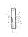
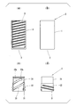
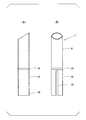
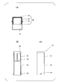
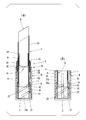
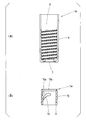
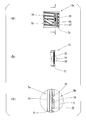
- FIG. 1 It is a side sectional view showing a lipstick container of a 1st embodiment of the present invention. It is a figure which shows the outer cylinder and inner cylinder in the lipstick container of 1st Embodiment, (a) is front sectional drawing of an outer cylinder, (b) is a front view of an outer cylinder, (c) is an inner cylinder Front sectional drawing of (d) is a front view of an inner cylinder. It is a figure which shows the inner cylinder in the lipstick container of 1st Embodiment, (a) is a side sectional view, (b) is a front view.
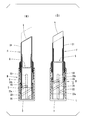
- the lipstick container of 1st Embodiment WHEREIN It is a figure which shows the state when drawing out a lipstick to a fixed position, (a) is side surface sectional drawing, (b) is front sectional drawing.
- the lipstick container of 1st Embodiment is a figure which shows the state at the time of use, (a) is side surface sectional drawing when consuming a lipstick in a fixed position, (b) when drawing out a lipstick from the state of (a) Side sectional view of FIG.
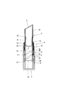
- the lipstick container of 1st Embodiment WHEREIN It is a side sectional view when the front-end
- it is a side sectional view showing the state when drawing out a lipstick to a fixed position.
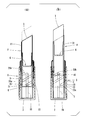
- the lipstick container of the modification of 1st Embodiment WHEREIN It is a figure which shows the state at the time of use, (a) is side surface sectional drawing when consuming lipstick in a fixed position, (b) is lipstick from the state of (a) It is a side sectional view when extending. It is side surface sectional drawing which shows the lipstick container of 2nd Embodiment of this invention. It is a figure which shows the outer cylinder and inner cylinder of 2nd Embodiment, (a) is front sectional drawing of an outer cylinder, (b) is front sectional drawing of an inner cylinder.
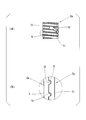
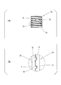
- FIG. 14 It is a figure which shows the inner cylinder which is a modification of 2nd Embodiment, (a) is a front view of the inner cylinder which changed (a) of FIG. 14, (b) has changed (a) of FIG. It is a front view of an inner cylinder.
- the lipstick container of 2nd Embodiment it is a side sectional view when the lipstick is drawn out to a fixed position.
- Front sectional drawing which shows, (b) is a front sectional view of an inner cylinder.
- the vertical direction is referred to as “axial direction”
- the horizontal direction is referred to as “horizontal direction” or “direction orthogonal to the axial direction”
- upper direction is referred to as “upper”
- lower direction is referred to as “upper”.
- the axial direction is also a direction along the central axis of a container main body B (outer cylindrical body D, inner cylindrical body E, middle cylindrical body F, and middle disc body G) described later.
- the lipstick container A of 1st Embodiment which concerns on this invention is demonstrated with reference to FIGS. 1-7.
- the lipstick container A includes a container body B for delivering the lipstick k by a turning operation, and a cap C detachably mounted so as to cover the upper portion of the container body B.
- the container body B has a bottomed cylindrical outer cylinder D, an inner cylinder E whose outer peripheral surface is screwed to the inner peripheral surface of the outer cylinder D, and a middle cylinder which rotatably supports the inner cylinder E.
- a body F, and a center plate body G which accommodates a lipstick k and which can not rotate and move up and down in the middle cylinder F are provided.
- the outer cylindrical body D is extended inward from the lower end portion of the cylindrical outer peripheral wall 1 extending in the axial (vertical) direction and the outer peripheral wall 1 And a disc-shaped bottom wall 2.
- a female screw portion 3 is screwed on the inner peripheral surface of the outer peripheral wall 1 so as to have a gentle inclination with respect to the circumferential direction and to have a small pitch as compared with a spiral groove 23 of the inner cylinder E described later. ing.
- a mounting cylinder 10 is attached to the upper portion of the outer cylinder D.
- the mounting cylinder 10 is substantially the same as the mounting cylinder 10, and the insertion cylinder 11 is non-rotatably inserted into the upper portion of the inner peripheral surface of the outer peripheral wall 1 of the outer cylinder D. It has a flange portion 12 projecting outward from the middle portion, a cap mounting portion 13 whose upper portion is attached and detached by a cap C from the flange portion 12, and an annular ridge 14 whose diameter is reduced from an upper end portion of the cap mounting portion 13.
- a seal cylinder 16 is non-rotatably attached to the inside of the mounting cylinder 10.
- the seal cylinder 16 is made of an elastic material, and the upper end of the inner peripheral surface of the seal cylinder 16 is in airtight and slidable contact with the outer peripheral surface of the middle cylindrical body F.
- the inner cylinder E is equipped with the cylindrical-shaped main-body part 21 lower than the height of the outer peripheral wall 1 of the outer cylinder D.
- the main body portion 21 is shorter than the outer cylinder D in the axial direction.
- the main body portion 21 is screwed on the outer peripheral surface of the lower portion of the main body portion 21 and has a male screw portion 22 screwed with the female screw portion 3 of the outer cylindrical portion D, and two spirals formed on the inner peripheral surface of the main body portion 21
- the groove 23 and the outer peripheral surface of the upper portion of the main body portion 21 interfere with the insertion cylindrical portion 11 of the mounting cylinder 10.
- the upper reduced diameter portion 24 is smaller in diameter than the lower portion of the main body portion 21.
- the two spiral grooves 23 are formed to have a larger pitch than the pitch of the external thread 22 engaged with the internal thread 3 of the outer cylinder D, and the upper end of the slope 23a.
- a horizontal portion 23b formed on the The inclined portion 23 a extends obliquely with respect to the circumferential direction of the main body portion 21.
- the inclined upper end is one end of the inclined portion 23a in the direction in which the inclined portion 23a extends, and is an end positioned above the other end.
- the horizontal portion 23 is a flat portion along the horizontal direction, and is also a flat portion along a direction orthogonal to the direction along the central axis of the inner cylinder E, or a flat portion along a direction parallel to the circumferential direction of the main body 21 is there.
- the two spiral grooves 23 are formed to have a pitch larger than the pitch of the external thread 22 engaged with the internal thread 3 of the outer cylinder D, but the present invention is not limited thereto. .
- the working resistance when the female screw portion 3 of the outer cylinder D and the male screw portion 22 of the inner cylinder E are screwed together is the screw groove of the inner disc G and the spiral groove of the inner cylinder E.
- the two spiral grooves 23 When it is smaller than the operation resistance at the time of screwing with 23, the two spiral grooves 23 have a pitch smaller than the pitch of the external thread 22 to be screwed with the internal thread 3 of the outer cylinder D. It may be formed.
- the inner cylindrical body F is provided rotatably with respect to the inner cylindrical body E in a state where the inner cylindrical body F is prevented from coming off inside the seal cylinder 16 by the locking projection 34 of the middle part. .
- the intermediate portion is a portion of the intermediate body F which is located substantially in the middle in the axial direction, and the locking projection 34 protrudes radially outward from the intermediate portion.
- the middle cylindrical body F includes a storage cylindrical portion 31 positioned above the locking projection 34 of the middle portion and a guide cylindrical portion 32 positioned below the locking projection 34.
- the guide cylindrical portion 32 is formed with two slit portions 33 extending in the axial direction and facing each other. The two slit portions 33 are opposed in the radial direction of the guide cylindrical portion 32.
- the inner disc body G is located at the upper part, and a cylindrical disc side wall 41 accommodating the lipstick k And a ring-shaped plate bottom wall 42 having a central portion open, and radially projecting from the inner peripheral surface of the plate side wall 41 in order to hold the lower portion of the lipstick k on the inner plate G.
- the cylindrical guide cylinder wall is provided with a plurality of axially extending storage ribs 43 and a lower end portion of the countersunk side wall 41 and the outer peripheral surface is in sliding contact with the inner peripheral surface of the guide cylindrical portion 32 of the middle cylindrical body F. And 44.
- Screwing pins 45 are provided in a protruding manner.
- the screwing pin 45 protrudes radially outward from the guide cylinder wall 44.
- the cap C includes a disc-like top wall 51 having a bulge from the peripheral edge toward the center, and a cylindrical side circumferential wall 52 hanging from the outer edge of the top wall 51.
- the side peripheral wall 52 is formed so as to have an inner diameter that the inner peripheral surface contacts the outer peripheral surface of the cap mounting portion 13 of the mounting cylinder 10 and is fitted to the mounting cylinder 10.
- tip part of the lipstick k protrudes from the storage cylinder part 31 of the inner cylinder F, and the lipstick k can be used.
- the horizontal portion 23 b of the spiral groove 23 may form an opening penetrating the main body portion 21 of the inner cylindrical body E.
- the maximum amount of extension of the lipstick k can be set.
- the size of the pitch of the spiral groove 23 formed in the inner cylindrical body E and the pitch of the female screw portion 3 formed in the outer cylindrical body D can be freely set, and the amount (length) of the lipstick k to be fed out It can be selected as appropriate.
- the screwing pin 45 of the inner disc body G has a small operating resistance when screwed into the spiral groove 23 of the inner cylindrical body E, so the inner disc body G smoothly forms the slit portion 33 of the inner cylindrical body F.
- the tip of the lipstick k can be returned to the inside of the storage cylinder 31.
- the inner cylindrical body E is the inner periphery of the outer cylindrical body D by the rotation of the female screw portion 3 of the outer cylindrical body D screwed with the male screw portion 22. Roll up little by little while being restricted from rotating along the surface. That is, the inner cylinder E is separated from the bottom wall 2 of the outer cylinder D.
- the inner plate G containing the lipstick k rolls up along the slit portion 33 of the inner cylinder F.
- the tip part of the lipstick k protrudes from the storage cylinder part 31 of the middle cylinder F, and the lipstick k can be used.
- the inner cylinder E can be advanced to the upper limit position where the upper end of the inner cylinder E abuts on the locking projection 34 of the middle cylinder F.
- the screwing pin 45 of the inner disc body G has an operation resistance when the screwing pin 45 of the inner disc body G and the spiral groove 23 of the inner cylindrical body E are engaged with the spiral groove 23 of the inner cylinder E
- the inner disc body G smoothly and middle cylinder It can be lowered along the slit 33 of the body F, and the tip of the lipstick k can be returned into the storage cylinder 31.
- the inner cylinder E When the inner cylinder E is rotated clockwise with respect to the middle cylinder F (when the outer cylinder D is viewed from the lower side in the axial direction), the inner cylinder E is a female screw of the outer cylinder D screwed with the male screw 22. By rotation of 3, along with the inner peripheral surface of the outer cylinder D, it rolls up, controlling rotation.
- the lipstick container A includes a container body B for delivering the lipstick k by a turning operation, and a cap C detachably mounted so as to cover the upper portion of the container body B.
- the container body B has a bottomed cylindrical outer cylinder Da, an inner cylinder Ea whose outer peripheral surface is screwed to the inner peripheral surface of the outer cylinder Da, and a middle cylinder which rotatably supports the inner cylinder Ea.
- a body F, and a center plate body G which accommodates a lipstick k and which can not rotate and move up and down in the middle cylinder F are provided.
- the outer cylindrical body Da has a cylindrical outer peripheral wall 6 extending in the axial direction, and a bottom wall 7 extending inward from the lower end portion of the outer peripheral wall 6.
- a screw thread portion 8 is formed on the inner peripheral surface of the outer peripheral wall 6 from the lower end portion to the middle of the upper portion so as to be screwed with a screw groove portion 72 of an inner cylindrical body Ea described later.
- the mounting cylinder 60 is attached to the upper part of the outer cylinder Da.
- a seal cylinder 61 is non-rotatably attached to the inside of the mounting cylinder 60.
- the seal cylinder 61 is made of an elastic material, and the upper end of the inner peripheral surface of the seal cylinder 61 is in airtight and slidable contact with the outer peripheral surface of the middle cylindrical body F.
- the inner cylindrical body Ea has a cylindrical main body 71 lower than the height of the outer peripheral wall 6 of the outer cylindrical body Da, and the lower end to the upper end of the outer peripheral surface of the main body 71 It has a screw groove 72 (screw portion) screwed up to the screw thread portion 8 of the outer cylindrical body Da, and two spiral grooves 73 formed by penetrating the main body portion 71 in the radial direction. Further, the two spiral grooves 73 are formed in the inclined portion 73a formed at a pitch larger than the pitch of the screw groove 72 engaged with the screw thread portion 8 of the outer cylinder Da and the inclined upper end of the inclined portion 73a. And a horizontal portion 73b.
- the horizontal portion 73b is a flat portion along the horizontal direction and is also a flat portion along a direction perpendicular to the direction along the central axis of the inner cylinder Ea, and is also a flat portion along a direction parallel to the circumferential direction of the main body 71 is there.
- the screw groove 72 and the screw thread 8 of the outer cylinder Da are screwed into the screw groove 72 screwed on the outer peripheral surface of the main body 71.
- the interference protrusion 74 is formed along the upper surface of the screw groove 72 only one turn from the lower end of the main body 71. That is, the interference projection 74 is an interference projection which protrudes downward from the upper surface of the screw groove 72 and extends along the upper surface for one rotation starting from the lower end of the main body 71 in the screw groove 72.
- the interference protrusion 74 is formed along the upper surface of the screw groove 72, but is not limited thereto.
- the interference projection 74 may be formed on any portion of the screw groove 72.
- the interference projection 74 is formed along the bottom of the screw groove 72. It may be done. That is, the interference projection 74 protrudes outward in the radial direction of the main body 71 from the bottom of the screw groove 72, and the bottom of the screw groove 72 in one turn from the lower end of the main body 71 in the screw groove 72. It may be an interference protrusion extending along the Alternatively, the screw groove 72 may be alternately provided on the upper surface and the lower surface. That is, the interference projection 74 includes a first interference projection projecting downward from the upper surface of the screw groove 72 and a second interference projection projecting upward from the lower surface of the screw groove 72. The first and second interference protrusions may be alternately provided on the upper surface and the lower surface of the screw groove 72 for one rotation starting from the lower end portion of the main body 71.
- the interference protrusion 74 is provided only for one turn of the screw groove 72 starting from the lower end of the main body 71. This is because, as shown in (a) of FIG. 11, when the inner cylindrical body Ea is raised along the inner circumferential surface of the outer cylindrical body Da, the screw thread portion 8 of the outer cylindrical body Da is inside the outer peripheral wall 6 It is because it is not screwed to the upper end of a surrounding surface. This is because it is easier to manufacture by reducing the number of turns of the screw thread portion 8 to be screwed in forming the outer cylinder Da.
- the interference projection 74 may be formed in any portion of the entire length of the screw groove portion 72. Absent.
- the interference protrusions 74 need not be formed continuously along the screw groove 72, but may be formed intermittently.
- the inner cylindrical body F is provided rotatably with respect to the inner cylindrical body Ea in a state where the inner cylindrical body F is prevented from coming off inside the seal cylinder 61 by the locking projection 34 of the middle part. .
- the middle portion is located approximately at the middle of the axial direction of the intermediate F.
- the middle cylindrical body F includes a storage cylindrical portion 31 positioned above the locking projection 34 of the middle portion, and a guide cylindrical portion 32 positioned below the locking projection 34.
- the guide cylindrical portion 32 is formed with two slit portions 33 extending in the axial direction and facing each other. The two slit portions 33 are opposed in the radial direction of the guide cylindrical portion 32.
- the inner plate body G is a ring located at the upper portion and formed inward from the lower end portion of the cylindrical plate side wall 41 storing the lipstick k and the lower end portion of the plate side wall 41. And a plurality of storage ribs extending in the axial direction and protruding in the radial direction from the inner peripheral surface of the countersunk side wall 41 in order to hold the lower portion of the bottom plate 42 of the 43 and a cylindrical guide cylinder wall 44 which is vertically provided from the lower end of the countersunk side wall 41 and whose outer peripheral surface is in sliding contact with the inner peripheral surface of the guide cylindrical portion 32 of the middle cylindrical body F.
- the cap C includes a disc-like top wall 51 having a bulge from the peripheral edge toward the center, and a cylindrical side circumferential wall 52 hanging from the outer edge of the top wall 51.
- the peripheral wall 52 is fitted to the mounting cylinder 60 such that the inner circumferential surface is in contact with the outer peripheral surface of the mounting cylinder 60.
- the bulge of the top 51 bulges upward.
- the cap C is removed from the container body B of the lipstick container A shown in FIG. Furthermore, after removing the inner cover 50 from the middle cylindrical body F, while holding the storage cylindrical portion 31 of the middle cylindrical body F with fingers, the outer peripheral wall 6 of the outer cylindrical body Da against the middle cylindrical body F (the outer cylinder When the body D is pivoted clockwise as viewed from the lower side in the axial direction, the working resistance when the screw thread portion 8 of the outer cylindrical body Da and the screw groove portion 72 of the inner cylindrical body Ea are screwed together is shown in FIG. And as shown in FIG.
- the screwing pin 45 screwed into the spiral groove 73 of the inner cylindrical body Ea of the inner disc body G is the slit 33 of the inner cylindrical body F.
- the screwing pin 45 of the inner tray G lifts from the inclined portion 73a of the spiral groove 73 to the continuous horizontal portion 73b.
- the inner plate G stops moving up at a fixed position, and as shown in FIG. 17, the tip of the lipstick k protrudes from the storage cylinder 31 of the inner cylinder F, and uses the lipstick k. Can.
- the interference protrusion 74 is formed in the screw groove portion 72 of the inner cylinder Ea. Therefore, the working resistance at the time when the screw thread portion 8 of the outer cylindrical body Da and the screw groove portion 72 of the inner cylindrical body Ea are screwed together is the screwing pin 45 of the inner disc G and the spiral groove 73 of the inner cylindrical body Ea. It can be stably increased more than the operation resistance when screwing together.
- the shape and size of the interference protrusion 74 formed in the screw groove portion 72 of the inner cylindrical body Ea can be appropriately set in accordance with the required magnitude of the operating resistance.
- the interference protrusion 77 extends radially outward of the valve moving portion 76 at the central portion of the valve moving portion 76 in the direction in which the screw groove 72 extends. Protruding towards.
- the valve moving portion 76 is formed laterally along the screw groove 72, but is not limited thereto.
- the valve moving portion may be a valve moving portion 78 formed in the longitudinal direction so as to intersect the screw groove 72 as shown in (a) to (c) of FIG. In this case, in the thin-walled valve moving portion 78, the left and right ends are separated by a gap s2 along the vertical direction intersecting the screw groove portion 72, and the interference projection 79 is formed at the position intersecting the screw groove portion 72 of the valve moving portion 78. It is done.
- the main body portion 71 has a gap s2 extending along the longitudinal direction intersecting the screw groove portion 72, and the thin-walled valve operating portion 78 is opposed to the circumferential direction forming the gap s2 in the main body portion 71.
- the interference projection 77 is formed in such a manner that the left and right ends are separated from the two surfaces, and extends in the longitudinal direction intersecting the screw groove 72, and the interference projection 77 intersects the screw groove 72 of the valve operating portion 78. Is formed.
- Both ends of the valve moving parts 76 and 78 shown in (a) to (c) of FIG. 14 and (a) to (c) of FIG. 15 are connected to the main body part 71. That is, both ends of the valve moving portion 76 in the extending direction of the screw groove 72 are connected to the main body 71, and both ends of the valve moving portion 78 in the vertical direction intersecting the screw groove 72 are connected to the main body 71 It is done.
- the valve moving part 76 a having a cantilever structure in which only one side is connected to the main body 71 and the other side is separated by the gap s1 or s2 , 78a may be used. That is, as shown in FIG.
- one end of the valve moving portion in the extending direction of the screw groove 72 is connected to the main body 71, and the other end is separated by the gap s1.
- It may be the valve moving part 76a which is not connected to the part 71, and as shown in FIG. 16 (b), one end of the both ends in the vertical direction intersecting the screw groove 72 is connected to the main body 71, The other end may be a valve moving portion 78 a separated by the gap s 2 and not connected to the main body 71.
- the valve operating parts 76, 76a, 78, 78a can stabilize the operating resistance if they are formed at least one place in the inner cylinder Ea, but a plurality of valve operating parts are mutually on the circumference of the inner cylinder Ea.
- valve moving parts 76 and 76a extending in the extending direction of the screw groove 72 are formed at positions facing each other in the extending direction of the screw groove 72 on the outer peripheral surface of the inner cylinder Ea. It is preferable that a plurality of vertically extending valve moving portions 78, 78a intersecting the screw groove portion 72 be formed at positions facing each other in the radial direction on the outer peripheral surface of the inner cylinder Ea.
- the interference projections 77, 77a, 79, 79a supported by the valve moving portions 76, 76a, 78, 78a instead of the interference projections 74 are formed on the inner cylinder Ea. 74 and the interference projections 77, 77a, 79, 79a supported by the valve operating portions 76, 76a, 78, 78a may be used in combination.
- the operating resistance when the screw thread portion 8 of the outer cylindrical body Da and the screw groove portion 72 of the inner cylindrical body Ea are screwed is an interference protrusion on the screw groove portion 72 of the inner cylindrical body Ea.
- the thin-walled valve member 76, 76a, 78, 78a having 77, 77a, 79, 79a, the screw thread portion 8 of the outer cylinder Da is in contact with the interference projection 77, 77a, 79, 79a.
- the interference protrusions 77, 77a, 79 which provide the operation resistance even if there is a dimensional error in the screw thread portion 8 of the outer cylinder Da and the screw groove 72 of the inner cylinder Ea.
- the elastically deformable valve moving portions 76, 76a, 78, 78a, 79a can be made to project and retract in the radial direction.
- the lipstick container of the present invention comprises an engaging portion provided on the outer cylindrical body D, Da, and an engaged portion provided on the inner cylindrical body E, Ea and capable of engaging with the engaging portion.
- the engagement portion is a rib 80 provided at the lower end portion of the inner peripheral surface of the outer peripheral wall 1 or 6 of the outer cylindrical body D, Da.
- the step is provided at the lower end of the outer peripheral surface of the main body 21 or 71 of the inner cylindrical body E or Ea and can be engaged with the rib 80 82 may be sufficient.
- the rib 80 is formed near one end (lower end) located on the lower side of both ends in the spiral direction of the screw thread portion 8 and radially inward from the inner peripheral surface of the outer peripheral wall 6 It is a projection which is projected toward.
- the spiral direction of the thread portion 8 means a direction along the spiral shape of the thread portion 8 itself.
- the rib 80 is a protrusion extending along the spiral direction of the screw thread portion 8 as shown in FIG. Although a protrusion such as the rib 80 is described as an example, the rib 80 may be replaced with a protrusion having another shape.
- the shape of the protrusion is not limited as long as the protrusion can be in contact with the side surface 83 of the step 82 by lowering the inner cylindrical members E and Ea as described later. Therefore, instead of the rib 80, a projection may be provided which does not extend along the spiral direction of the screw thread portion 8.
- the stepped portion 82 is a notch formed by cutting the main body portion 71 of the inner cylindrical body E, Ea upward from the lower end face thereof.
- the step 82 has a side 83 facing in the direction of rotation so that the inner cylinder E, Ea rolls down, and an upper surface 84 extending from the upper end of the side 83 along the spiral direction of the screw groove 72 and facing downward.
- the spiral direction of the screw groove 72 means the direction along the spiral shape of the screw groove 72 itself.
- the stepped portion 80 is a notch having a shape shown in (a) and (b) of FIG. Although a notch such as the step 80 is described as an example, a notch having another shape may be provided instead of the step 80.
- the shape of the notch is not limited as long as the notch is provided with a side surface that can abut against the rib 80 by lowering the inner cylinder E, Ea. Therefore, instead of the step portion 80, a cutting having a shape which is recessed radially inward from the outer peripheral surface of the main body portions 21, 71 without penetrating the main body portions 21, 71 of the inner cylindrical bodies E, Ea in the radial direction. A notch may be provided.
- the side surface 83 forming the step 82 is one end (upper end) 81 located on the upper side of both ends of the rib 80 in the direction along the extending rib 80 , Can be gradually brought close to contact.
- the ribs 80 (protrusions, engaging portions) of the outer cylindrical bodies D, Da and the step portions 82 (notches, engaged portions) of the inner cylindrical bodies E, Ea can be engaged with each other.
- a rib 80 protrusion, engaging portion is formed near one end (lower end) located on the lower side of both ends in the spiral direction of the screw thread portion 8.
- the inner cylinder bodies E and Ea You can stop the As a result, next, when the inner cylindrical bodies E and Ea move up with respect to the outer cylindrical bodies D and Da, the main body portions 21 and 71 of the inner cylindrical bodies E and Ea and the bottom walls of the outer cylindrical bodies D and Da Since the inner cylinder E and Ea move up from a state where they are separated by a predetermined distance from each other in the axial direction, the main body 21 and 71 of the inner cylinder E and Ea and the bottom of the outer cylinder D and Da The surface contact with the walls 2 and 7 can prevent the inner cylinders E and Ea from being easily carried up with respect to the outer cylinders D and Da.
- the above-mentioned predetermined distance is suitably set by adjusting the position of rib 80 (protrusion,
- the lipstick container of the present invention can be suitably used as a lipstick container for accommodating recent soft lipsticks, since it is possible for the user to prevent the lipstick from being broken by mistake by the user at the start of use.
Landscapes
- Engineering & Computer Science (AREA)
- Mechanical Engineering (AREA)
- Containers And Packaging Bodies Having A Special Means To Remove Contents (AREA)
Abstract
容器本体(B)と、キャップ(C)とを備える口紅容器(A)であって、容器本体(B)は、螺合ピン(45)が設けられた中皿体(G)と、中筒体(F)と、螺合ピン(45)と螺合する螺旋溝(23)が形成された内筒体(E)と、外筒体(D)とを備え、外筒体(D)を回動することにより、中皿体(G)と内筒体(E)の一方が定位置に繰り上がるとともに、一方が定位置に達した後は、外筒体(D)を回動することにより、中皿体(G)と内筒体(E)の他方が繰り上がる口紅容器(A)。
Description
本発明は、回動操作により口紅を繰り出す口紅容器に関し、とくに、硬度が柔らかい口紅を収納する口紅容器に関するものである。本願は、2017年12月27日に日本に出願された日本国特願2017-250775号と、2018年3月30日に日本に出願された日本国特願2018-069860号とに基づき優先権を主張し、その内容をここに援用する。
口紅などの棒状化粧料を収納する円筒状の繰出容器は、従来から知られている(例えば、特許文献1参照)。この繰出容器は、容器本体と、容器本体に装着するキャップとを備え、容器本体は、棒状化粧料を収納する中皿体と、中皿体を回転不能かつ上下動可能に収容する内筒体(中筒体)と、内筒体の外周面に沿って回動することにより、中皿体を上下動する外筒体とを備える。この繰出容器では、キャップを外した後、内筒体を把持しながら、外筒体を回動させることにより、内筒体から棒状化粧料を中皿体の上下動により出没させて使用する。
また、棒状化粧品(口紅)を必要以上に繰り出してしまうことによる棒状化粧品の折損等の事故を防止する繰出容器も、従来から知られている(例えば、特許文献2参照)。この繰出容器では、カバー(キャップ)を外すと、化粧品受皿(中皿体)と螺筒の螺合体がばねにより上方に規定量押し上げられるようにして、棒状化粧品の繰り出し量を適正量に定めることができる。また、少量繰出し操作部材を付設したことにより、棒状化粧品が消耗したときは、少量繰出し操作部材の累進操作により簡単に棒状化粧品の消耗分を補充できる。
しかし、最近の傾向として、繰出容器に収納される口紅は、硬度が柔らかくなる方向に進んでいる。そのため、上記特許文献1記載の繰出容器では、使用者が、容器から口紅を出し過ぎてしまい、口紅を根元から折ってしまうことがある。また、上記特許文献2記載の繰出容器では、当初の口紅の繰り出し量を、化粧するには充分であるがそれ以上不必要に繰り出し過ぎないように抑えて、口紅の折損等の事故を防止できるが、当初の口紅の繰り出し量を調節できない。
本発明は、上記問題を解決することを課題とし、使用開始時に使用者が誤って口紅を出し過ぎて、口紅が折れたりすることを防止できる口紅容器を提供することを目的とする。
上記の課題を解決するため、本発明の第1の態様として、容器本体と、容器本体に装着するキャップとを備える口紅容器であって、容器本体は、口紅を収納し、螺合ピンが設けられた中皿体と、中皿体を回転不能かつ上下動可能に案内する中筒体と、中皿体の螺合ピンと螺合する螺旋溝が形成され、中筒体の外周面に沿って回動することにより中皿体を上下動する内筒体と、内筒体の外周面に内周面が螺合される外筒体とを備え、外筒体を回動することにより、中皿体と内筒体の一方が定位置に繰り上がるとともに、一方が定位置に達した後は、外筒体を回動することにより、中皿体と内筒体の他方が繰り上がる口紅容器、という手段を採用する。
本発明の第2の態様として、上記第1の態様において、螺合する外筒体と内筒体との間の作動抵抗は、螺合する中皿体の螺合ピンと内筒体の螺旋溝との間の作動抵抗よりも大きい口紅容器、という手段を採用する。本発明の第3の態様として、上記第1の態様において、螺合する外筒体と内筒体との間の作動抵抗は、螺合する中皿体の螺合ピンと内筒体の螺旋溝との間の作動抵抗よりも小さい口紅容器、という手段を採用する。本発明の第4の態様として、上記第1または2の態様において、内筒体は、外筒体に螺合するねじ部を備え、螺旋溝のピッチがねじ部のピッチよりも大きい口紅容器、という手段を採用する。本発明の第5の態様として、上記第1または3の態様において、内筒体は、外筒体に螺合するねじ部を備え、螺旋溝のピッチがねじ部のピッチよりも小さい口紅容器、という手段を採用する。本発明の第6の態様として、上記第1~5のいずれか1つの態様において、内筒体は、螺旋溝の上端部に設けられ、内筒体の中心軸線に沿う方向に直交する方向に沿う平面部分を有する口紅容器、という手段を採用する。本発明の第7の態様として、上記第2、4、及び6の態様において、内筒体は、外筒体に螺合するねじ部を備え、ねじ部に干渉突起が形成されている口紅容器、という手段を採用する。本発明の第8の態様として、上記第7の態様において、干渉突起は、間欠的に形成されている口紅容器、という手段を採用する。第9の態様として、上記第7または8の態様において、干渉突起は、径方向に弾性変形可能な弁動部に形成されている口紅容器、という手段を採用する。
本発明の口紅容器は、口紅を収納し、螺合ピンが設けられた中皿体と、中皿体を回転不能かつ上下動可能に案内する中筒体と、中皿体の螺合ピンと螺合する螺旋溝が形成され、中筒体の外周面に沿って回動することにより中皿体を上下動する内筒体と、内筒体の外周面に内周面を螺合される外筒体とを備え、外筒体を回動することにより口紅を定位置まで繰り出すとともに、口紅が定位置に達した後は、外筒体をより強い力で回動することにより口紅が少しずつ繰り出される。これにより、使用開始時に使用者が誤って口紅を出し過ぎることがなく、口紅が折れたりすることを防止できる。また、本発明の口紅容器は、内筒体のねじ部に干渉突起が形成されている。そのために、外筒体の内周面と内筒体の外周面とが螺合する際の作動抵抗は、中皿体の螺合ピンと内筒体の螺旋溝とが螺合する際の作動抵抗よりも安定的に大きくすることができる。その結果、使用開始時に、外筒体を回動すると、内筒体が外筒体と一体で回動し、中皿体を定位置まで繰り上げることができる。
次に、本発明の口紅容器について、各実施形態を示した図面を参照して説明する。本発明の範囲は、以下の実施の形態に限定されず、本発明の技術的思想の範囲内で任意に変更可能である。なお、以下の説明において、図1において、上下方向を「軸線方向」とし、左右方向を「水平方向」又は「軸線方向に直交する方向」とし、上方向を「上」とし、下方向を「下」とし、左方向を「正面」とし、右方向を「背面」とする。なお、軸線方向は、後述する容器本体B(外筒体D、内筒体E、中筒体F、および中皿体G)の中心軸線に沿う方向でもある。
(第1実施形態)
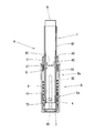
本発明に係る第1実施形態の口紅容器Aを図1から図7を参照して説明する。図1において、口紅容器Aは、回動操作することにより、口紅kを繰り出す容器本体Bと、容器本体Bの上部を覆うように、着脱自在に装着されるキャップCとを備える。容器本体Bは、有底円筒状の外筒体Dと、外筒体Dの内周面に外周面が螺合される内筒体Eと、内筒体Eを回転可能に支持する中筒体Fと、口紅kを収納し、中筒体F内に回転不能かつ上下動可能に収容される中皿体Gとを備える。
本発明に係る第1実施形態の口紅容器Aを図1から図7を参照して説明する。図1において、口紅容器Aは、回動操作することにより、口紅kを繰り出す容器本体Bと、容器本体Bの上部を覆うように、着脱自在に装着されるキャップCとを備える。容器本体Bは、有底円筒状の外筒体Dと、外筒体Dの内周面に外周面が螺合される内筒体Eと、内筒体Eを回転可能に支持する中筒体Fと、口紅kを収納し、中筒体F内に回転不能かつ上下動可能に収容される中皿体Gとを備える。
図2の(a)および(b)に示すように、外筒体Dは、軸線(上下)方向に延びる円筒状の外周壁1と、外周壁1の下端部から内方に延設される円板状の底壁2とを有する。外周壁1の内周面には、雌ねじ部3が、後述する内筒体Eの螺旋溝23と比べて、周方向に対して緩やかな傾斜を備え、かつ小さいピッチを備えるように螺設されている。
図1に示すように、外筒体Dの上部には、装着筒10が取り付けられている。装着筒10は、図4の(a)に示すように、外筒体Dの外周壁1のうち内周面の上部に回動不能に嵌挿される差し込み筒部11と、装着筒10の略中間部から外方に突出するフランジ部12と、フランジ部12より上部がキャップCにより着脱されるキャップ装着部13と、キャップ装着部13の上端部から縮径する環状突条14とを有する。装着筒10の内側には、シール筒16が回動不能に取り付けられている。シール筒16は、弾性材料からなり、シール筒16の内周面の上端が、中筒体Fの外周面に気密に、かつ摺動可能に接触している。
図2の(c)および(d)に示すように、内筒体Eは、外筒体Dの外周壁1の高さよりも低い円筒状の本体部21を備える。すなわち、本体部21は、軸線方向に外筒体Dよりも短い。本体部21は、本体部21の下部の外周面に螺設され、外筒部Dの雌ねじ部3と螺合する雄ねじ部22と、本体部21の内周面に形成される2条の螺旋溝23と、本体部21の上部の外周面に形成され、内筒体Eが外筒体Dの内周面に沿って繰り上げられた際に、装着筒10の差し込み筒部11との干渉を避けるための上部縮径部24とを有する。上部縮径部24は、本体部21の下部よりも縮径されている。また、2条の螺旋溝23は、外筒体Dの雌ねじ部3と螺合する雄ねじ部22のピッチよりも大きなピッチを備えるように形成される傾斜部分23aと、傾斜部分23aの傾斜上端部に形成される水平部分23bとからなる。傾斜部分23aは、本体部21の周方向に対して傾斜して延在している。傾斜上端部は、傾斜部分23aが延在する方向における傾斜部分23aの一端部であり、他端部よりも上側に位置する端部である。水平部分23は、水平方向に沿う平面部分であり、内筒体Eの中心軸線に沿う方向に直交する方向に沿う平面部分でもあり、本体部21の周方向に平行な方向に沿う平面部分でもある。なお、本実施形態では、2条の螺旋溝23は、外筒体Dの雌ねじ部3と螺合する雄ねじ部22のピッチよりも大きなピッチを備えるように形成されているが、これに限定されない。後述するように、外筒体Dの雌ねじ部3と内筒体Eの雄ねじ部22とが螺合する際の作動抵抗が、中皿体Gの螺合ピン45と内筒体Eの螺旋溝23とが螺合する際の作動抵抗よりも小さい場合には、2条の螺旋溝23は、外筒体Dの雌ねじ部3と螺合する雄ねじ部22のピッチよりも小さなピッチを備えるように形成されていても構わない。
図1に示すように、中筒体Fは、中間部の係止突部34によってシール筒16の内側に抜け止めされた状態で、内筒体Eに対して回動自在に設けられている。中間部は、中間体Fのうち軸線方向の略中間に位置している部分であり、係止突部34は、中間部から径方向外側に向けて突設されている。図3に示すように、中筒体Fは、中間部の係止突部34より上部に位置する収納筒部31と、係止突部34より下部に位置するガイド筒部32とを備える。ガイド筒部32には、軸線方向に延び、対向する2本のスリット部33が形成されている。2本のスリット部33は、ガイド筒部32の径方向に対向している。
図1および図4の(b)および(c)に示すように、中皿体Gは、上部に位置し、口紅kを収納する円筒状の皿側壁41と、皿側壁41の下端部から内方に形成され、中心部が開口するリング状の皿底壁42と、口紅kの下部を中皿体Gに保持するために、皿側壁41の内周面から径方向に突設されているとともに、軸線方向に延びる複数本の収納リブ43と、皿側壁41の下端部から垂設され、中筒体Fのガイド筒部32の内周面に外周面が摺接する円筒状の案内筒壁44とを有する。
さらに、案内筒壁44の下端部の外周面には、中筒体Fのガイド筒部32に形成されたスリット部33を貫通し、内筒体Eの螺旋溝23と螺合する2個の螺合ピン45が突設されている。螺合ピン45は、案内筒壁44から径方向外側に向けて突設されている。ここで、外筒体Dの雌ねじ部3と内筒体Eの雄ねじ部22とが螺合する際の作動抵抗と、中皿体Gの螺合ピン45と内筒体Eの螺旋溝23とが螺合する際の作動抵抗とは、一方が他方よりも大きくなるように設定されている。
図1に示すように、キャップCは、周縁から中心に向けて膨らみを有する円板状の頂壁51と、頂壁51の外縁から垂設される円筒状の側周壁52とを備える。側周壁52は、内周面が装着筒10のキャップ装着部13の外周面に接触して装着筒10に嵌合する内径を備えるように形成されている。
次に、本実施形態の使用方法と作用効果について図面を参照しながら説明する。口紅kを使用する際には、図1に示す口紅容器Aの容器本体BからキャップCを外した後、中筒体Fの収納筒部31を手指で把持しながら、外筒体Dの外周壁1を中筒体Fに対して(外筒体Dを軸線方向の下側から見て)時計回りに回動させる。このとき、外筒体Dの雌ねじ部3と内筒体Eの雄ねじ部22とが螺合する際の作動抵抗が、中皿体Gの螺合ピン45と内筒体Eの螺旋溝23とが螺合する際の作動抵抗よりも大きくなるように設定されている場合には、使用開始時に、内筒体Eは、外筒体Dと一体で回動する。
そして、内筒体Eが外筒体Dと一体で回動すると、中皿体Gは、内筒体Eの螺旋溝23に螺合する螺合ピン45が、中筒体Fのスリット部33に沿って繰り上がり始めるとともに、繰り上がり始める。やがて、図5の(b)に示すように、中皿体Gの螺合ピン45は、内筒体Eの回動に伴い、螺旋溝23の傾斜部分23aの傾斜上端部まで繰り上がると、傾斜部分23aから連続する水平部分23bにより、中皿体Gは、定位置で繰り上がりを停止する。これにより、図5の(a)に示すように、口紅kの先端部は、中筒体Fの収納筒部31から突出し、口紅kを使用することができる。なお、螺旋溝23の水平部分23bは、内筒体Eの本体部21に貫通された開口部を形成してもよい。
このように、口紅容器Aを使用する際に、使用者が誤って外筒体Dを一気に回動したとしても、図1、および図5の(a)および(b)に示す初期状態(使用開始状態)では、内筒体Eの螺旋溝23の傾斜部分23aのピッチが大きいことから、口紅kを収納する中皿体Gは、ストレスなく図5の(a)および(b)に示す位置まで上昇する。しかし、中皿体Gをさらに上昇させるために内筒体Eを外筒体Dに対して上昇させるには、外筒体Dを初期状態より大きい力で回動する必要があるため、口紅kを中筒体Fの収納筒部31から出し過ぎて折ってしまうことを防止できる。以上のように、図2の(c)に示す内筒体Eの本体部21の内周面に形成される螺旋溝23の軸線方向の長さ(高さ)を調整することにより、初期状態での口紅kの最大繰り出し量を設定することができる。なお、内筒体Eに形成される螺旋溝23や外筒体Dに形成される雌ねじ部3のピッチの大きさは、自由に設定することが可能で、繰り出す口紅kの量(長さ)に応じて適宜選択することができる。
次に、口紅kを使用後、図5の(a)および(b)に示す状態から口紅kの先端部を中筒体Fの収納筒部31内に収納した状態に戻す際には、外筒体Dの外周壁1を中筒体Fに対して(外筒体Dを軸線方向の下側から見て)反時計回りに回動する。このとき、内筒体Eは、外筒体Dの内周面上で繰り上がっていない。すなわち、内筒体Eは、外筒体Dの底壁部2に接している。そのために、外筒体Dの雌ねじ部3と、雄ねじ部22により螺合された内筒体Eは、外筒体Dと一体で回動する。すると、中皿体Gの螺合ピン45は、内筒体Eの螺旋溝23に螺合する際の作動抵抗が小さいことにより、中皿体Gは、スムースに中筒体Fのスリット部33に沿って下降し、口紅kの先端部を収納筒部31内に戻すことができる。
次に、図6の(a)に示すように、口紅kを中筒体Fから繰り出して使用することにより口紅kが消耗した場合について説明する。この場合には、中筒体Fの収納筒部31を手指で把持しながら、外筒体Dの外周壁1を中筒体Fに対して(外筒体Dを軸線方向の下側から見て)時計回りに回動しようとしても、内筒体Eのうち螺旋溝23の上端部である水平部分23bに中皿体Gの螺合ピン45が係合している。そのために、内筒体Eは、初期状態と同等の力で外筒体Dを回動しても、これ以上回動できない。しかし、初期状態より大きい力で外筒体Dを回動すると、内筒体Eは、雄ねじ部22と螺合する外筒体Dの雌ねじ部3の回動によって、外筒体Dの内周面に沿って回転を規制されながら少しずつ繰り上がる。すなわち、内筒体Eは、外筒体Dの底壁部2から離間する。
これと同時に、図6の(b)に示すように、口紅kを収納する中皿体Gは、中筒体Fのスリット部33に沿って繰り上がる。これにより、口紅kの先端部は、中筒体Fの収納筒部31から突出し、口紅kを使用することができる。さらに、口紅kを使用することにより口紅kが消耗した場合には、図6の(a)および(b)で説明したように、外筒体Dをさらに回動することにより、図7に示すように、内筒体Eの上端が中筒体Fの係止突部34に当接する上限位置まで内筒体Eを繰り上げることができる。
口紅kを使用後、図6の(b)に示す状態から口紅kの先端部を中筒体Fの収納筒部31内に収納した状態に戻す際には、外筒体Dの外周壁1を中筒体Fに対して(外筒体Dを軸線方向の下側から見て)反時計回りに回動する。このとき、内筒体Eは、中皿体Gの螺合ピン45により回動が規制されないために、外筒体Dの雌ねじ部3と雄ねじ部22により螺合される内筒体Eは、外筒体Dと一体で回動する。そのため、内筒体Eが外筒体Dの内周面に沿って繰り下がることは、ほとんどない。すると、中皿体Gの螺合ピン45は、内筒体Eの螺旋溝23に、中皿体Gの螺合ピン45と内筒体Eの螺旋溝23が螺合する際の作動抵抗が外筒体Dの雌ねじ部3と内筒体Eの雄ねじ部22とが螺合する際の作動抵抗よりも小さくなるように螺合されていることにより、中皿体Gは、スムースに中筒体Fのスリット部33に沿って下降し、口紅kの先端部を収納筒部31内に戻すことができる。
(変形例)
次に、本発明に係る第1実施形態の変形例を図8から図9の(a)及び(b)を参照して説明する。第1実施形態の変形例として、外筒体Dの雌ねじ部3と内筒体Eの雄ねじ部22とが螺合する際の作動抵抗が、中皿体Gの螺合ピン45と内筒体Eの螺旋溝23とが螺合する際の作動抵抗よりも小さくなるように設定されている場合を説明する。このような場合には、図1に示す口紅容器Aの容器本体BからキャップCを外した後、中筒体Fの収納筒部31を手指で把持しながら、外筒体Dの外周壁1を中筒体Fに対して(外筒体Dを軸線方向の下側から見て)時計回りに回動すると、内筒体Eは、雄ねじ部22と螺合する外筒体Dの雌ねじ部3の回動によって、外筒体Dの内周面に沿って、回転を規制されながら繰り上がる。
次に、本発明に係る第1実施形態の変形例を図8から図9の(a)及び(b)を参照して説明する。第1実施形態の変形例として、外筒体Dの雌ねじ部3と内筒体Eの雄ねじ部22とが螺合する際の作動抵抗が、中皿体Gの螺合ピン45と内筒体Eの螺旋溝23とが螺合する際の作動抵抗よりも小さくなるように設定されている場合を説明する。このような場合には、図1に示す口紅容器Aの容器本体BからキャップCを外した後、中筒体Fの収納筒部31を手指で把持しながら、外筒体Dの外周壁1を中筒体Fに対して(外筒体Dを軸線方向の下側から見て)時計回りに回動すると、内筒体Eは、雄ねじ部22と螺合する外筒体Dの雌ねじ部3の回動によって、外筒体Dの内周面に沿って、回転を規制されながら繰り上がる。
これと同時に、図8に示すように、口紅kを収納する中皿体Gは、中筒体Fに沿って繰り上がることによって、口紅kの先端部は、中筒体Fの収納筒部31から突出し、口紅kを使用することができる。さらに、口紅kを使用することにより、図9の(a)に示すように、口紅kが消耗した場合には、外筒体Dをさらに回動することにより、図9の(b)に示すように、中皿体Gの螺合ピン45は、内筒体Eの回動に伴い、螺旋溝23の傾斜部分23aの傾斜上端部まで繰り上げることができる。
(第2実施形態)
次に、本発明に係る第2実施形態を図10から図13及び図17を参照して説明する。第2実施形態として、使用開始時に、口紅容器Aを回動させると、確実に中皿体Gが先に繰り上がり、その後、必要に応じて内筒体Eが繰り上がるように、外筒体Dに対する内筒体Eの作動抵抗を安定させるために、第1実施形態の外筒体Dおよび内筒体Eの構成を変更した場合を説明する。以下、第1実施形態と同一の構成部分には同一の符号を付し、外筒体Dおよび内筒体Eにおける変更部分に新たな符号を付し、相違点を中心に説明する。
次に、本発明に係る第2実施形態を図10から図13及び図17を参照して説明する。第2実施形態として、使用開始時に、口紅容器Aを回動させると、確実に中皿体Gが先に繰り上がり、その後、必要に応じて内筒体Eが繰り上がるように、外筒体Dに対する内筒体Eの作動抵抗を安定させるために、第1実施形態の外筒体Dおよび内筒体Eの構成を変更した場合を説明する。以下、第1実施形態と同一の構成部分には同一の符号を付し、外筒体Dおよび内筒体Eにおける変更部分に新たな符号を付し、相違点を中心に説明する。
図10において、口紅容器Aは、回動操作することにより、口紅kを繰り出す容器本体Bと、容器本体Bの上部を覆うように、着脱自在に装着されるキャップCとを備える。容器本体Bは、有底円筒状の外筒体Daと、外筒体Daの内周面に外周面が螺合される内筒体Eaと、内筒体Eaを回転可能に支持する中筒体Fと、口紅kを収納し、中筒体F内に回転不能かつ上下動可能に収容される中皿体Gとを備える。
図11の(a)に示すように、外筒体Daは、軸線方向に延びる円筒状の外周壁6と、外周壁6の下端部から内方に延設される底壁7とを有し、外周壁6の内周面には、ねじ山部8が、後述する内筒体Eaのねじ溝部72と螺合するように、下端部から上部の途中まで形成されている。図10に示すように、外筒体Daの上部には、装着筒60が取り付けられている。装着筒60の内側には、シール筒61が回動不能に取り付けられている。シール筒61は、弾性材料からなり、シール筒61の内周面の上端が、中筒体Fの外周面に気密にかつ摺動可能に接触している。
図11の(b)に示すように、内筒体Eaは、外筒体Daの外周壁6の高さよりも低い円筒状の本体部71と、本体部71の外周面の下端部から上端部まで螺設され、外筒体Daのねじ山部8と螺合するねじ溝部72(ねじ部)と、本体部71を径方向に貫通して形成される2条の螺旋溝73とを有する。また、2条の螺旋溝73は、外筒体Daのねじ山部8と螺合するねじ溝部72のピッチよりも大きなピッチで形成される傾斜部分73aと、傾斜部分73aの傾斜上端部に形成される水平部分73bとからなる。水平部分73bは、水平方向に沿う平面部分であり、内筒体Eaの中心軸線に沿う方向に直交する方向に沿う平面部分でもあり、本体部71の周方向に平行な方向に沿う平面部分でもある。
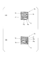
図12の(a)および(b)に示すように、本体部71の外周面に螺設されたねじ溝部72には、ねじ溝部72と、外筒体Daのねじ山部8とが螺合する際の作動抵抗を増大するために、本体部71の下端部から1周だけ、ねじ溝部72の上面に沿って干渉突起74が形成されている。すなわち、干渉突起74は、ねじ溝部72の上面から下方に向けて突出するとともに、ねじ溝部72のうち本体部71の下端部から始まる1周分に上面に沿って延在する干渉突起である。ただし、本実施形態では、干渉突起74は、ねじ溝部72の上面に沿って形成されているが、これに限定されない。干渉突起74は、ねじ溝部72のどの部分に形成されていてもよく、例えば、図13の(a)および(b)に示すように、干渉突起74は、ねじ溝部72の底面に沿って形成されていてもよい。すなわち、干渉突起74は、ねじ溝部72の底面から本体部71の径方向外方に向けて突出するとともに、ねじ溝部72のうち本体部71の下端部から1周分に、ねじ溝部72の底面に沿って延在する干渉突起でもよい。また、ねじ溝部72の上面と下面とに交互に設けられていてもよい。すなわち、干渉突起74は、ねじ溝部72の上面から下方に向けて突出する第1干渉突起と、ねじ溝部72の下面から上方に向けて突出する第2干渉突起とを備え、ねじ溝部72のうち本体部71の下端部から始まる1周分に、第1干渉突起および第2干渉突起がねじ溝部72の上面と下面とに交互に設けられている干渉突起でもよい。
さらに、本実施形態では、干渉突起74は、本体部71の下端部から始まるねじ溝部72の1周分だけに設けられている。これは、内筒体Eaが外筒体Daの内周面に沿って繰り上がる際に、図11の(a)に示すように、外筒体Daのねじ山部8が外周壁6の内周面の上端まで螺設されていないためである。これは、外筒体Daの成型に当たって、螺設されるねじ山部8の周回数を少なくする方が製造し易いからである。しかしながら、外筒体Daのねじ山部8を外周壁6の内周面の上端まで螺設するのであれば、干渉突起74は、ねじ溝部72の全長のうちどの部分に形成されていても構わない。また、干渉突起74は、ねじ溝部72に沿って、連続して形成される必要はなく、間欠に形成されていてもよい。
図10に示すように、中筒体Fは、中間部の係止突部34によってシール筒61の内側に抜け止めされた状態で、内筒体Eaに対して回動自在に設けられている。中間部は、中間体Fの軸線方向の略中間に位置している。中筒体Fは、中間部の係止突部34より上部に位置する収納筒部31と、係止突部34より下部に位置するガイド筒部32とを備える。ガイド筒部32には、軸線方向に延び、対向する2本のスリット部33が形成されている。2本のスリット部33は、ガイド筒部32の径方向に対向している。
図10に示すように、中皿体Gは、上部に位置し、口紅kを収納する円筒状の皿側壁41と、皿側壁41の下端部から内方に形成され、中心部が開口するリング状の皿底壁42と、口紅kの下部を中皿体Gに保持するために、皿側壁41の内周面から径方向に突設されているとともに、軸線方向に延びる複数本の収納リブ43と、皿側壁41の下端部から垂設され、中筒体Fのガイド筒部32の内周面に外周面が摺接する円筒状の案内筒壁44とを有する。さらに、案内筒壁44の下端部の外周面には、中筒体Fのガイド筒部32に形成されたスリット部33を貫通し、内筒体Eaの螺旋溝73と螺合する2個の螺合ピン45が突設されている。
また、中皿体Gに収納される口紅kに含まれる揮発成分の揮散を防止するとともに、摩耗粉や塵などの進入を防止するために、図10に示すように、中筒体Fの収納筒部31の上端部に、内カバー50が装着されている。図10に示すように、キャップCは、周縁から中心に向けて膨らみを有する円板状の頂壁51と、頂壁51の外縁から垂設される円筒状の側周壁52とを備え、側周壁52は、内周面が装着筒60の外周面に接触するように装着筒60に嵌合されている。頂部51の膨らみは、上方に膨出している。
次に、本実施形態の使用方法と作用効果について図面を参照しながら説明する。口紅kを使用する際には、図10に示す口紅容器Aの容器本体BからキャップCを外す。さらに、中筒体Fから内カバー50を外した後、中筒体Fの収納筒部31を手指で把持しながら、外筒体Daの外周壁6を中筒体Fに対して(外筒体Dを軸線方向の下側から見て)時計回りに回動すると、外筒体Daのねじ山部8と内筒体Eaのねじ溝部72とが螺合する際の作動抵抗は、図12および図13に示すように、内筒体Eaのねじ溝部72に干渉突起74が形成されているために、中皿体Gの螺合ピン45と内筒体Eaの螺旋溝73とが螺合する際の作動抵抗よりも確実に大きくすることができる。これにより、使用開始時に、内筒体Eaは、外筒体Daと一体で回動する。
さらに、内筒体Eaが外筒体Daと一体で回動すると、中皿体Gは、内筒体Eaの螺旋溝73に螺合する螺合ピン45が、中筒体Fのスリット部33に沿って繰り上がり始めるとともに、繰り上がり始める。やがて、中皿体Gの螺合ピン45は、内筒体Eaの回動に伴い、螺旋溝73の傾斜部分73aから連続する水平部分73bまで繰り上がる。これにより、中皿体Gは、定位置で繰り上がりを停止し、図17に示すように、口紅kの先端部は、中筒体Fの収納筒部31から突出し、口紅kを使用することができる。
以上のように、本実施形態では、内筒体Eaのねじ溝部72に干渉突起74が形成されている。そのために、外筒体Daのねじ山部8と内筒体Eaのねじ溝部72とが螺合する際の作動抵抗は、中皿体Gの螺合ピン45と内筒体Eaの螺旋溝73とが螺合する際の作動抵抗よりも安定的に大きくすることができる。なお、内筒体Eaのねじ溝部72に形成される干渉突起74の形状や大きさは、必要とする作動抵抗の大きさに応じて適宜設定することができる。
(変形例)
次に、本発明に係る第2実施形態の変形例1を、図14から図16を参照して説明する。第2実施形態の変形例として、内筒体Eaのねじ溝部72に形成される干渉突起74に換えて、図14の(a)~(c)に示すように、ねじ溝部72に沿う隙間s1によって上下端が分離された薄肉の弁動部76と、弁動部76の中央部に形成された干渉突起77とが設けられた内筒体Eaについて説明する。すなわち、本体部71は、ねじ溝部72に沿って延在する隙間s1を備え、薄肉の弁動部76は、本体部71のうち隙間s1を形成する上面及び下面から上下端が分離されるように形成されるとともに、ねじ溝部72が延在する方向に延在し、干渉突起77は、ねじ溝部72が延在する方向における弁動部76の中央部に弁動部76の径方向外側に向けて突出している。本変形例では、弁動部76は、ねじ溝部72に沿って横方向に形成されているが、これに限定されない。弁動部は、図15の(a)~(c)に示すように、ねじ溝部72と交差して縦方向に形成された弁動部78でもよい。この場合には、薄肉の弁動部78は、ねじ溝部72と交差する縦方向に沿う隙間s2によって左右端が分離され、弁動部78のねじ溝部72と交差する位置に干渉突起79が形成されている。すなわち、本体部71は、ねじ溝部72と交差する縦方向に沿って延在する隙間s2を備え、薄肉の弁動部78は、本体部71のうち隙間s2を形成する周方向に対向する2つの面から左右端が分離されるように形成されるとともに、ねじ溝部72と交差する縦方向に延在し、干渉突起77は、弁動部78のねじ溝部72と交差する位置に干渉突起79が形成されている。
次に、本発明に係る第2実施形態の変形例1を、図14から図16を参照して説明する。第2実施形態の変形例として、内筒体Eaのねじ溝部72に形成される干渉突起74に換えて、図14の(a)~(c)に示すように、ねじ溝部72に沿う隙間s1によって上下端が分離された薄肉の弁動部76と、弁動部76の中央部に形成された干渉突起77とが設けられた内筒体Eaについて説明する。すなわち、本体部71は、ねじ溝部72に沿って延在する隙間s1を備え、薄肉の弁動部76は、本体部71のうち隙間s1を形成する上面及び下面から上下端が分離されるように形成されるとともに、ねじ溝部72が延在する方向に延在し、干渉突起77は、ねじ溝部72が延在する方向における弁動部76の中央部に弁動部76の径方向外側に向けて突出している。本変形例では、弁動部76は、ねじ溝部72に沿って横方向に形成されているが、これに限定されない。弁動部は、図15の(a)~(c)に示すように、ねじ溝部72と交差して縦方向に形成された弁動部78でもよい。この場合には、薄肉の弁動部78は、ねじ溝部72と交差する縦方向に沿う隙間s2によって左右端が分離され、弁動部78のねじ溝部72と交差する位置に干渉突起79が形成されている。すなわち、本体部71は、ねじ溝部72と交差する縦方向に沿って延在する隙間s2を備え、薄肉の弁動部78は、本体部71のうち隙間s2を形成する周方向に対向する2つの面から左右端が分離されるように形成されるとともに、ねじ溝部72と交差する縦方向に延在し、干渉突起77は、弁動部78のねじ溝部72と交差する位置に干渉突起79が形成されている。
図14の(a)~(c)および図15の(a)~(c)に示す弁動部76、78は、両端が本体部71と連結されている。すなわち、弁動部76は、ねじ溝部72が延在する方向における両端が本体部71に連結されており、弁動部78は、ねじ溝部72と交差する縦方向における両端が本体部71に連結されている。ただし、弁動部は、図16の(a)および(b)に示すように、片側だけが本体部71と連結され、他側が隙間s1またはs2によって分離された片持ち構造の弁動部76a、78aであっても構わない。すなわち、弁動部は、図16の(a)に示すように、ねじ溝部72が延在する方向における両端のうち、一端が本体部71と連結され、他端が隙間s1によって分離されて本体部71に連結されていない弁動部76aであってもよく、図16の(b)に示すように、ねじ溝部72と交差する縦方向における両端のうち、一端が本体部71と連結され、他端が隙間s2によって分離されて本体部71に連結されていない弁動部78aであってもよい。弁動部76、76a、78、78aは、内筒体Eaに少なくとも1箇所形成されていれば作動抵抗を安定させることができるが、複数の弁動部が内筒体Eaの周上の互いに対向する位置に形成されていることがより好ましい。すなわち、ねじ溝部72が延在する方向に延在する複数の弁動部76、76aが、内筒体Eaの外周面において、ねじ溝部72が延在する方向に互いに対向する位置に形成されることが好ましく、ねじ溝部72と交差する縦方向に延在する複数の弁動部78、78aが、内筒体Eaの外周面において、径方向に互いに対向する位置に形成することが好ましい。また、本変形例では、干渉突起74の代わりに弁動部76、76a、78、78aに支持された干渉突起77、77a、79、79aを内筒体Eaに形成しているが、干渉突起74と、弁動部76、76a、78、78aに支持された干渉突起77、77a、79、79aとを併用しても構わない。
次に、本変形例の使用方法と作用効果について図面を参照しながら説明する。外筒体Daのねじ山部8と内筒体Eaのねじ溝部72とが螺合する際の作動抵抗は、図14~図16に示すように、内筒体Eaのねじ溝部72に干渉突起77、77a、79、79aを有する薄肉の弁動部76、76a、78、78aが形成されていることにより、干渉突起77、77a、79、79aに外筒体Daのねじ山部8が当接すると、弁動部76、76a、78、78aの弾性変形により干渉突起77、77a、79、79aが径方向に押圧される。これにより、外筒体Daのねじ山部8と内筒体Eaのねじ溝部72とが螺合する際に、適度な作動抵抗を付与することができる。
以上のように、本変形例では、外筒体Daのねじ山部8と内筒体Eaのねじ溝部72とに寸法誤差があっても、作動抵抗を付与する干渉突起77、77a、79、79aは、弾性変形可能な弁動部76、76a、78、78aに支持されることにより、径方向に出没させることができる。これにより、外筒体Daのねじ山部8と内筒体Eaのねじ溝部72とが螺合する際に、適度な作動抵抗を付与しつつ、両者をスムースに螺合させることができる。
以上、図面を参照しながら本発明の実施形態及び変形例について説明したが、本発明は上記実施形態及び変形例に限定されるものではない。
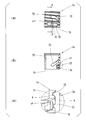
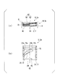
本発明の口紅容器は、外筒体D、Daに設けられた係合部と、内筒体E、Eaに設けられ、係合部に係合可能な被係合部とを備え、係合部と被係合部を係合することにより外筒体D、Daと内筒体E、Eaとの相対回転を規制するストッパー装置を備えてもよい。例えば、係合部は、図18の(a)に示すように、外筒体D、Daの外周壁1、6の内周面のうち下端部に設けられたリブ80であり、被係合部は、図18の(a)および(b)に示すように、内筒体E、Eaの本体部21、71の外周面のうち下端部に設けられ、リブ80と係合可能な段部82でもよい。
より詳しく説明すると、リブ80は、ねじ山部8の螺旋方向における両端部のうち下側に位置する一端部(下端部)の近くに形成され、外周壁6の内周面から径方向内側に向けて突出している突起である。ねじ山部8の螺旋方向とは、ねじ山部8自体の螺旋形状に沿う方向を意味する。リブ80は、図18の(a)に示すように、ねじ山部8の螺旋方向に沿って延在している突起である。一例として
リブ80のような突起を説明しているが、リブ80の代わりに別の形状を有する突起を設けてもよい。後述するように内筒体E、Eaを繰り下げることにより段部82の側面83に当接可能な突起であるならば、突起の形状は限定されない。そのため、リブ80の代わりに、ねじ山部8の螺旋方向に沿って延在しない突起を設けてもよい。
リブ80のような突起を説明しているが、リブ80の代わりに別の形状を有する突起を設けてもよい。後述するように内筒体E、Eaを繰り下げることにより段部82の側面83に当接可能な突起であるならば、突起の形状は限定されない。そのため、リブ80の代わりに、ねじ山部8の螺旋方向に沿って延在しない突起を設けてもよい。
段部82は、内筒体E、Eaの本体部71をその下端面から上方に向けて凹むように切り欠いて形成されている切り欠きである。段部82は、内筒体E、Eaが繰り下がるように回転する方向に向く側面83と、側面83の上端からねじ溝部72の螺旋方向に沿って延在し、下方を向く上面84とを備える。ねじ溝部72の螺旋方向とは、ねじ溝部72自体の螺旋形状に沿う方向を意味する。段部80は、図18の(a)および(b)に示す形状を有する切り欠きである。一例として段部80のような切り欠きを説明しているが、段部80の代わりに別の形状を有する切り欠きを設けてもよい。後述するように、内筒体E、Eaを繰り下げることによりリブ80に当接可能な側面を備える切り欠きであるならば、切り欠きの形状は限定されない。そのため、段部80の代わりに、内筒体E、Eaの本体部21、71を径方向に貫通せずに、本体部21、71の外周面から径方向内側に向けて凹む形状を有する切り欠きを設けてもよい。
このようなリブ80(突起、係合部)を備える外筒体D、Da及び段部82(切り欠き、被係合部)を備える内筒体E、Eaによれば、外筒体D、Daに対して内筒体E、Eaを繰り下げることにより、段部82を形成する側面83を、延在するリブ80に沿う方向におけるリブ80の両端のうち上側に位置する一端(上端)81に、徐々に近づけて当接させることができる。これにより、外筒体D、Daのリブ80(突起、係合部)と、内筒体E、Eaの段部82(切り欠き、被係合部)とを係合させることができるため、外筒体D、Daと内筒体E、Eaとの相対回転を規制することができる。さらに、リブ80(突起、係合部)が、ねじ山部8の螺旋方向における両端部のうち下側に位置する一端部(下端部)の近くに形成されている。これにより、内筒体E、Eaの本体部21、71と、外筒体D、Daの底壁2、7とが軸線方向で所定の距離離間している位置において、内筒体E、Eaの繰り下げを停止させることができる。その結果、次に、外筒体D、Daに対して内筒体E、Eaが繰り上がる際に、内筒体E、Eaの本体部21、71と、外筒体D、Daの底壁2、7とが軸線方向で所定の距離離間している状態から内筒体E、Eaが繰り上がるため、内筒体E、Eaの本体部21、71と、外筒体D、Daの底壁2、7とが面接触することにより外筒体D、Daに対して内筒体E、Eaが繰り上がり難くなること、を防止することができる。なお、上記の所定の距離は、種々の条件を考慮して、外筒体D、Daの軸線方向におけるリブ80(突起、係合部)の位置を調節することにより適宜設定される。
上述した実施形態及び変形例に示した各構成部材の諸形状や組み合わせ等は一例であって、本発明の趣旨から逸脱しない範囲において設計要求等に基づき種々変更可能である。例えば、本発明の趣旨を逸脱しない範囲で、上記実施形態及び変形例に示した各構成要素を適宜組み合わせてもよい。
本発明の口紅容器は、使用開始時に使用者が誤って口紅を出し過ぎて、口紅が折れたりすることを防止できるので、最近の硬度が柔らかい口紅を収納する口紅容器として好適に利用できる。
A 口紅容器
B 容器本体
C キャップ
D、Da 外筒体
E、Ea 内筒体
F 中筒体
G 中皿体
k 口紅
s1、s2 隙間
1、6 外周壁
2、7 底壁
3 雌ねじ部
8 ねじ山部
10、60 装着筒
11 差し込み筒部
12 フランジ部
13 キャップ装着部
14 環状突条
16、61 シール筒
21、71 本体部
22 雄ねじ部(ねじ部)
23、73 螺旋溝
23a、73a 傾斜部分
23b、73b 水平部分(平面部分)
24 上部縮径部
31 収納筒部
32 ガイド筒部
33 スリット部
34 係止突部
41 皿側壁
42 皿底壁
43 収納リブ
44 案内筒壁
45 螺合ピン
50 内カバー
51 頂壁
52 側周壁
72 ねじ溝部(ねじ部)
74、77、77a、79、79a 干渉突起
76、76a、78、78a 弁動部
80 リブ(突起、係合部)
81 上端
82 段部(切り欠き、被係合部)
83 側面
84 上面
B 容器本体
C キャップ
D、Da 外筒体
E、Ea 内筒体
F 中筒体
G 中皿体
k 口紅
s1、s2 隙間
1、6 外周壁
2、7 底壁
3 雌ねじ部
8 ねじ山部
10、60 装着筒
11 差し込み筒部
12 フランジ部
13 キャップ装着部
14 環状突条
16、61 シール筒
21、71 本体部
22 雄ねじ部(ねじ部)
23、73 螺旋溝
23a、73a 傾斜部分
23b、73b 水平部分(平面部分)
24 上部縮径部
31 収納筒部
32 ガイド筒部
33 スリット部
34 係止突部
41 皿側壁
42 皿底壁
43 収納リブ
44 案内筒壁
45 螺合ピン
50 内カバー
51 頂壁
52 側周壁
72 ねじ溝部(ねじ部)
74、77、77a、79、79a 干渉突起
76、76a、78、78a 弁動部
80 リブ(突起、係合部)
81 上端
82 段部(切り欠き、被係合部)
83 側面
84 上面
Claims (10)
- 容器本体と、前記容器本体に装着するキャップとを備える口紅容器であって、
前記容器本体は、
口紅を収納し、螺合ピンが設けられた中皿体と、
前記中皿体を回転不能かつ上下動可能に案内する中筒体と、
前記中皿体の前記螺合ピンと螺合する螺旋溝が形成され、前記中筒体の外周で回動することにより前記中皿体を上下動する内筒体と、
前記内筒体の外周面に外周面が螺合される外筒体と、
を備え、
前記外筒体を回動することにより、前記中皿体と前記内筒体の一方が定位置に繰り上がるとともに、前記一方が定位置に達した後は、前記外筒体を回動することにより、前記中皿体と前記内筒体の他方が繰り上がる口紅容器。 - 前記外筒体と前記内筒体とが螺合する際の作動抵抗は、前記中皿体の前記螺合ピンと前記内筒体の前記螺旋溝とが螺合する際の作動抵抗よりも大きい請求項1に記載の口紅容器。
- 前記外筒体と前記内筒体とが螺合する際の作動抵抗は、前記中皿体の前記螺合ピンと前記内筒体の前記螺旋溝とが螺合する際の作動抵抗よりも小さい請求項1に記載の口紅容器。
- 前記内筒体は、前記外筒体に螺合するねじ部を備え、
前記螺旋溝のピッチが前記ねじ部のピッチよりも大きい請求項1または2に記載の口紅容器。 - 前記内筒体は、前記外筒体に螺合するねじ部を備え、
前記螺旋溝のピッチが前記ねじ部のピッチよりも小さい請求項1または3に記載の口紅容器。 - 前記内筒体は、前記螺旋溝の上端部に設けられ、前記内筒体の中心軸線に沿う方向に直交する方向に沿う平面部分を有する請求項1~5のいずれか1項に記載の口紅容器。
- 前記内筒体は、前記外筒体に螺合するねじ部を備え、
前記ねじ部に干渉突起が形成されている請求項2または6に記載の口紅容器。 - 前記ねじ部に干渉突起が形成されている請求項4に記載の口紅容器。
- 前記干渉突起は、前記ねじ部に沿って間欠的に形成されている請求項7または8に記載の口紅容器。
- 前記干渉突起は、径方向に弾性変形可能な弁動部に形成されている請求項7から9のいずれか1項に記載の口紅容器。
Priority Applications (5)
| Application Number | Priority Date | Filing Date | Title |
|---|---|---|---|
| US16/957,879 US11304496B2 (en) | 2017-12-27 | 2018-12-27 | Lipstick container |
| JP2019562137A JP6929384B2 (ja) | 2017-12-27 | 2018-12-27 | 口紅容器 |
| EP18895191.7A EP3733018B1 (en) | 2017-12-27 | 2018-12-27 | Lipstick container |
| CN201880084100.3A CN111526755B (zh) | 2017-12-27 | 2018-12-27 | 口红容器 |
| KR1020207017106A KR102542457B1 (ko) | 2017-12-27 | 2018-12-27 | 립스틱 용기 |
Applications Claiming Priority (4)
| Application Number | Priority Date | Filing Date | Title |
|---|---|---|---|
| JP2017250775 | 2017-12-27 | ||
| JP2017-250775 | 2017-12-27 | ||
| JP2018-069860 | 2018-03-30 | ||
| JP2018069860 | 2018-03-30 |
Publications (1)
| Publication Number | Publication Date |
|---|---|
| WO2019131821A1 true WO2019131821A1 (ja) | 2019-07-04 |
Family
ID=67067623
Family Applications (1)
| Application Number | Title | Priority Date | Filing Date |
|---|---|---|---|
| PCT/JP2018/047993 Ceased WO2019131821A1 (ja) | 2017-12-27 | 2018-12-27 | 口紅容器 |
Country Status (6)
| Country | Link |
|---|---|
| US (1) | US11304496B2 (ja) |
| EP (1) | EP3733018B1 (ja) |
| JP (1) | JP6929384B2 (ja) |
| KR (1) | KR102542457B1 (ja) |
| CN (1) | CN111526755B (ja) |
| WO (1) | WO2019131821A1 (ja) |
Cited By (2)
| Publication number | Priority date | Publication date | Assignee | Title |
|---|---|---|---|---|
| JP2021133112A (ja) * | 2020-02-28 | 2021-09-13 | 株式会社吉野工業所 | 繰出容器 |
| JP2022086884A (ja) * | 2020-11-30 | 2022-06-09 | 株式会社吉野工業所 | 繰出し容器 |
Families Citing this family (5)
| Publication number | Priority date | Publication date | Assignee | Title |
|---|---|---|---|---|
| US11717072B2 (en) * | 2018-07-11 | 2023-08-08 | Pat Mcgrath Cosmetics Llc | Lipstick arrangement |
| WO2022158684A1 (ko) * | 2021-01-20 | 2022-07-28 | 김엽 | 이중 트위스트 구조 및 이를 포함한 사물 출몰기구와 그 밀봉구조 |
| KR102568096B1 (ko) | 2022-12-27 | 2023-08-18 | 오윤탁 | 립스틱 케이스 |
| IT202300018033A1 (it) * | 2023-09-01 | 2025-03-01 | Cosmei S R L | Contenitore cosmetico |
| KR102646439B1 (ko) * | 2023-12-04 | 2024-03-11 | 지윤정 | 탄성 걸림 구조를 갖는 스틱형 화장품 용기 |
Citations (9)
| Publication number | Priority date | Publication date | Assignee | Title |
|---|---|---|---|---|
| JPS6073418U (ja) * | 1983-10-25 | 1985-05-23 | 釜屋化学工業株式会社 | 繰出容器 |
| JPS64838U (ja) | 1987-06-17 | 1989-01-05 | ||
| JP2004000343A (ja) | 2002-05-31 | 2004-01-08 | Yoshino Kogyosho Co Ltd | 棒状化粧料の収納皿 |
| JP2006334368A (ja) * | 2005-06-05 | 2006-12-14 | Mikio Kuzuu | 口紅等の収納容器 |
| JP2008036372A (ja) * | 2006-08-05 | 2008-02-21 | Mikio Kuzuu | 口紅等の収納容器 |
| JP2008043590A (ja) * | 2006-08-18 | 2008-02-28 | Tokiwa Corp | 充填物押出容器 |
| JP2008055025A (ja) * | 2006-09-01 | 2008-03-13 | Suzuno Kasei Kk | 棒状化粧材繰り出し容器 |
| JP2017025075A (ja) | 2011-08-12 | 2017-02-02 | 三菱瓦斯化学株式会社 | レジスト組成物、レジストパターン形成方法、それに用いるポリフェノール化合物及びそれから誘導され得るアルコール化合物 |
| JP2018069860A (ja) | 2016-10-26 | 2018-05-10 | 株式会社ヴァレオジャパン | 車両用の空調装置 |
Family Cites Families (8)
| Publication number | Priority date | Publication date | Assignee | Title |
|---|---|---|---|---|
| GB2026983A (en) * | 1978-07-20 | 1980-02-13 | Cardia E | Cosmetics containers |
| JPS64838Y2 (ja) | 1984-12-28 | 1989-01-10 | ||
| CN1066033C (zh) * | 1994-07-08 | 2001-05-23 | 株式会社希丹 | 一种化妆品容器 |
| JP2736039B2 (ja) * | 1994-08-25 | 1998-04-02 | 株式会社トキワ | 化粧料繰り出し容器 |
| EP1681979A1 (en) * | 2003-11-13 | 2006-07-26 | Unilever Plc | Fabric cleaning fluid and dispensing device |
| US20130230347A1 (en) * | 2012-07-24 | 2013-09-05 | Rnd Group Llc | Slide type lipstick case structure |
| WO2013191523A2 (ko) | 2013-07-24 | 2013-12-27 | Kim Yoon Hoi | 슬라이드형 립스틱 용기 |
| CN206761066U (zh) * | 2017-04-24 | 2017-12-19 | 苏州佑嘉塑胶科技有限公司 | 一种旋拧式防脱口红管 |
-
2018
- 2018-12-27 JP JP2019562137A patent/JP6929384B2/ja active Active
- 2018-12-27 EP EP18895191.7A patent/EP3733018B1/en active Active
- 2018-12-27 US US16/957,879 patent/US11304496B2/en active Active
- 2018-12-27 WO PCT/JP2018/047993 patent/WO2019131821A1/ja not_active Ceased
- 2018-12-27 CN CN201880084100.3A patent/CN111526755B/zh active Active
- 2018-12-27 KR KR1020207017106A patent/KR102542457B1/ko active Active
Patent Citations (9)
| Publication number | Priority date | Publication date | Assignee | Title |
|---|---|---|---|---|
| JPS6073418U (ja) * | 1983-10-25 | 1985-05-23 | 釜屋化学工業株式会社 | 繰出容器 |
| JPS64838U (ja) | 1987-06-17 | 1989-01-05 | ||
| JP2004000343A (ja) | 2002-05-31 | 2004-01-08 | Yoshino Kogyosho Co Ltd | 棒状化粧料の収納皿 |
| JP2006334368A (ja) * | 2005-06-05 | 2006-12-14 | Mikio Kuzuu | 口紅等の収納容器 |
| JP2008036372A (ja) * | 2006-08-05 | 2008-02-21 | Mikio Kuzuu | 口紅等の収納容器 |
| JP2008043590A (ja) * | 2006-08-18 | 2008-02-28 | Tokiwa Corp | 充填物押出容器 |
| JP2008055025A (ja) * | 2006-09-01 | 2008-03-13 | Suzuno Kasei Kk | 棒状化粧材繰り出し容器 |
| JP2017025075A (ja) | 2011-08-12 | 2017-02-02 | 三菱瓦斯化学株式会社 | レジスト組成物、レジストパターン形成方法、それに用いるポリフェノール化合物及びそれから誘導され得るアルコール化合物 |
| JP2018069860A (ja) | 2016-10-26 | 2018-05-10 | 株式会社ヴァレオジャパン | 車両用の空調装置 |
Non-Patent Citations (1)
| Title |
|---|
| See also references of EP3733018A4 |
Cited By (4)
| Publication number | Priority date | Publication date | Assignee | Title |
|---|---|---|---|---|
| JP2021133112A (ja) * | 2020-02-28 | 2021-09-13 | 株式会社吉野工業所 | 繰出容器 |
| JP7308780B2 (ja) | 2020-02-28 | 2023-07-14 | 株式会社吉野工業所 | 繰出容器 |
| JP2022086884A (ja) * | 2020-11-30 | 2022-06-09 | 株式会社吉野工業所 | 繰出し容器 |
| JP7427343B2 (ja) | 2020-11-30 | 2024-02-05 | 株式会社吉野工業所 | 繰出し容器 |
Also Published As
| Publication number | Publication date |
|---|---|
| KR20200101916A (ko) | 2020-08-28 |
| KR102542457B1 (ko) | 2023-06-12 |
| CN111526755A (zh) | 2020-08-11 |
| CN111526755B (zh) | 2023-03-24 |
| EP3733018B1 (en) | 2022-04-27 |
| US20200337439A1 (en) | 2020-10-29 |
| US11304496B2 (en) | 2022-04-19 |
| JPWO2019131821A1 (ja) | 2020-09-24 |
| EP3733018A1 (en) | 2020-11-04 |
| JP6929384B2 (ja) | 2021-09-01 |
| EP3733018A4 (en) | 2021-09-15 |
Similar Documents
| Publication | Publication Date | Title |
|---|---|---|
| WO2019131821A1 (ja) | 口紅容器 | |
| US9474349B2 (en) | Cosmetic dispenser with frictional resistance | |
| JP7206038B2 (ja) | 繰出容器 | |
| US9642439B2 (en) | Cosmetic dispenser with crenelated wall for frictional resistance | |
| JP6817046B2 (ja) | 繰出容器 | |
| JP7308698B2 (ja) | 繰出容器 | |
| JP2020025622A (ja) | 繰出容器 | |
| JP6980347B2 (ja) | 口紅容器 | |
| JP7175846B2 (ja) | 繰出し容器 | |
| JP7246273B2 (ja) | 繰出容器 | |
| JP2020018463A (ja) | 繰出容器 | |
| JP2023111706A (ja) | 繰出容器 | |
| WO2020153241A1 (ja) | 繰り出し容器 | |
| JP7211916B2 (ja) | 繰出し容器 | |
| KR102569160B1 (ko) | 정량 출몰 조절용 다각형 스틱 용기 | |
| JP2023144260A (ja) | 繰出容器 | |
| JP7016576B2 (ja) | 繰り出し容器 | |
| JP3221247U (ja) | 棒状化粧料容器 | |
| JP2025102506A (ja) | 繰出容器、繰出機構付き収容部、および下部操作機構 | |
| JP2021023449A (ja) | 繰出し容器 | |
| WO2023085176A1 (ja) | 繰出し容器 | |
| JPH0238664Y2 (ja) | ||
| JP2021160790A (ja) | 繰出し容器 | |
| JP2021171585A (ja) | 繰出し容器 | |
| JP2004147931A (ja) | 棒状化粧料繰り出し容器 |
Legal Events
| Date | Code | Title | Description |
|---|---|---|---|
| 121 | Ep: the epo has been informed by wipo that ep was designated in this application |
Ref document number: 18895191 Country of ref document: EP Kind code of ref document: A1 |
|
| ENP | Entry into the national phase |
Ref document number: 2019562137 Country of ref document: JP Kind code of ref document: A |
|
| NENP | Non-entry into the national phase |
Ref country code: DE |
|
| ENP | Entry into the national phase |
Ref document number: 2018895191 Country of ref document: EP Effective date: 20200727 |