WO2019131951A1 - 鞍乗型車両の収納ボックス給電構造 - Google Patents
鞍乗型車両の収納ボックス給電構造 Download PDFInfo
- Publication number
- WO2019131951A1 WO2019131951A1 PCT/JP2018/048337 JP2018048337W WO2019131951A1 WO 2019131951 A1 WO2019131951 A1 WO 2019131951A1 JP 2018048337 W JP2018048337 W JP 2018048337W WO 2019131951 A1 WO2019131951 A1 WO 2019131951A1
- Authority
- WO
- WIPO (PCT)
- Prior art keywords
- hook
- storage box
- terminal
- carrier
- side terminal
- Prior art date
- Legal status (The legal status is an assumption and is not a legal conclusion. Google has not performed a legal analysis and makes no representation as to the accuracy of the status listed.)
- Ceased
Links
Images


Classifications
-
- B—PERFORMING OPERATIONS; TRANSPORTING
- B62—LAND VEHICLES FOR TRAVELLING OTHERWISE THAN ON RAILS
- B62J—CYCLE SADDLES OR SEATS; AUXILIARY DEVICES OR ACCESSORIES SPECIALLY ADAPTED TO CYCLES AND NOT OTHERWISE PROVIDED FOR, e.g. ARTICLE CARRIERS OR CYCLE PROTECTORS
- B62J9/00—Containers specially adapted for cycles, e.g. panniers or saddle bags
- B62J9/20—Containers specially adapted for cycles, e.g. panniers or saddle bags attached to the cycle as accessories
- B62J9/24—Containers specially adapted for cycles, e.g. panniers or saddle bags attached to the cycle as accessories on specially adapted racks, e.g. for top or side cases
-
- B—PERFORMING OPERATIONS; TRANSPORTING
- B62—LAND VEHICLES FOR TRAVELLING OTHERWISE THAN ON RAILS
- B62J—CYCLE SADDLES OR SEATS; AUXILIARY DEVICES OR ACCESSORIES SPECIALLY ADAPTED TO CYCLES AND NOT OTHERWISE PROVIDED FOR, e.g. ARTICLE CARRIERS OR CYCLE PROTECTORS
- B62J11/00—Supporting arrangements specially adapted for fastening specific devices to cycles, e.g. supports for attaching maps
- B62J11/10—Supporting arrangements specially adapted for fastening specific devices to cycles, e.g. supports for attaching maps for mechanical cables, hoses, pipes or electric wires, e.g. cable guides
- B62J11/19—Supporting arrangements specially adapted for fastening specific devices to cycles, e.g. supports for attaching maps for mechanical cables, hoses, pipes or electric wires, e.g. cable guides specially adapted for electric wires
-
- B—PERFORMING OPERATIONS; TRANSPORTING
- B62—LAND VEHICLES FOR TRAVELLING OTHERWISE THAN ON RAILS
- B62J—CYCLE SADDLES OR SEATS; AUXILIARY DEVICES OR ACCESSORIES SPECIALLY ADAPTED TO CYCLES AND NOT OTHERWISE PROVIDED FOR, e.g. ARTICLE CARRIERS OR CYCLE PROTECTORS
- B62J45/00—Electrical equipment arrangements specially adapted for use as accessories on cycles, not otherwise provided for
-
- B—PERFORMING OPERATIONS; TRANSPORTING
- B62—LAND VEHICLES FOR TRAVELLING OTHERWISE THAN ON RAILS
- B62J—CYCLE SADDLES OR SEATS; AUXILIARY DEVICES OR ACCESSORIES SPECIALLY ADAPTED TO CYCLES AND NOT OTHERWISE PROVIDED FOR, e.g. ARTICLE CARRIERS OR CYCLE PROTECTORS
- B62J6/00—Arrangement of optical signalling or lighting devices on cycles; Mounting or supporting thereof; Circuits therefor
- B62J6/04—Rear lights
-
- B—PERFORMING OPERATIONS; TRANSPORTING
- B62—LAND VEHICLES FOR TRAVELLING OTHERWISE THAN ON RAILS
- B62J—CYCLE SADDLES OR SEATS; AUXILIARY DEVICES OR ACCESSORIES SPECIALLY ADAPTED TO CYCLES AND NOT OTHERWISE PROVIDED FOR, e.g. ARTICLE CARRIERS OR CYCLE PROTECTORS
- B62J9/00—Containers specially adapted for cycles, e.g. panniers or saddle bags
- B62J9/20—Containers specially adapted for cycles, e.g. panniers or saddle bags attached to the cycle as accessories
- B62J9/23—Containers specially adapted for cycles, e.g. panniers or saddle bags attached to the cycle as accessories above or alongside the rear wheel
-
- B—PERFORMING OPERATIONS; TRANSPORTING
- B62—LAND VEHICLES FOR TRAVELLING OTHERWISE THAN ON RAILS
- B62J—CYCLE SADDLES OR SEATS; AUXILIARY DEVICES OR ACCESSORIES SPECIALLY ADAPTED TO CYCLES AND NOT OTHERWISE PROVIDED FOR, e.g. ARTICLE CARRIERS OR CYCLE PROTECTORS
- B62J9/00—Containers specially adapted for cycles, e.g. panniers or saddle bags
- B62J9/20—Containers specially adapted for cycles, e.g. panniers or saddle bags attached to the cycle as accessories
- B62J9/27—Containers specially adapted for cycles, e.g. panniers or saddle bags attached to the cycle as accessories characterised by mounting arrangements, e.g. quick release arrangements
-
- B—PERFORMING OPERATIONS; TRANSPORTING
- B62—LAND VEHICLES FOR TRAVELLING OTHERWISE THAN ON RAILS
- B62J—CYCLE SADDLES OR SEATS; AUXILIARY DEVICES OR ACCESSORIES SPECIALLY ADAPTED TO CYCLES AND NOT OTHERWISE PROVIDED FOR, e.g. ARTICLE CARRIERS OR CYCLE PROTECTORS
- B62J43/00—Arrangements of batteries
- B62J43/30—Arrangements of batteries for providing power to equipment other than for propulsion
Definitions
- the present invention relates to a storage box feed structure for a straddle-type vehicle.
- Priority is claimed on Japanese Patent Application No. 2017-254999, filed Dec. 28, 2017, the content of which is incorporated herein by reference.
- a storage box feeding structure for a saddle-ride type vehicle includes a storage box having electric components inside and a carrier capable of detachably mounting the storage box on a vehicle body (for example, Patent Document 1).
- a carrier capable of detachably mounting the storage box on a vehicle body
- Patent Document 1 By attaching the storage box to the carrier, the carrier-side connector and the storage box-side connector are connected, and power can be supplied from the battery of the vehicle to the electrical components.
- a new feeding portion (box-side connector) is provided at the bottom of the storage box (the box-side facing portion facing the carrier-side facing portion).
- the shape of the carrier needs to be largely changed.
- vibration will enter a contact portion (hereinafter referred to as "contact portion") between the terminal on the storage box side and the terminal on the carrier side.
- the present invention provides a feed structure using an existing structure without providing a new feed portion in the storage box, and provides the feed portion at a portion having high resistance to vibration and high rigidity.
- the purpose is to provide.
- a storage box feeding structure for a saddle-ride type vehicle comprises a storage box (30), a carrier (50) capable of detachably mounting the storage box (30) on a vehicle body, and the storage A hook (33) enabling connection of the box (30) to the carrier (50); a hook receiving portion (53) for receiving the hook (33); And a hook side terminal (70) for feeding power, and the hook side terminal (70) provided in the hook receiving portion (53) and the storage box (30) is mounted on the carrier (50). And 70) a receiving terminal (80) connected thereto.
- the hook (33) is integrally provided with the hook side terminal (70) and extends in the front and rear direction. You may provide a part (33b).
- the front and rear extension portions (33b) extend upward than the hook side terminals (70), and the storage box (30) May be provided with a vertical wall (33d) that abuts on the lower surface of the carrier (50) when mounted on the carrier (50).
- the hook side terminal (70) is a male terminal, and at least a part of the hook side terminal (70) May be plate-like extended in the extension direction of the front and rear extension part (33b).
- the tip end (70t) of the hook side terminal (70) is the same as that of the hook (33). May be located inside the tip (33t)
- the hook surrounding the hook side terminal (70) inside the hook (33) A side case (110) may be provided, and the longitudinal length (L2) of the hook side terminal (70) may be shorter than the longitudinal length (L1) of the hook side case (110).
- the receiving terminal (80) is located on the lower surface side of the carrier (50). May be
- the receiving side terminal (80) is a female terminal, and the hook side terminal (70) ) May be provided.
- the pair of terminal pieces (81) may be opposed in the vehicle width direction.
- the hook receiving portion (53) encloses the receiving side terminal (80);
- a box-shaped receiving case (120) opened at the lower side may be provided.
- the hook (33) is provided with a lower extension (33a) extending downward from the lower portion of the storage box (30). And a rear extension (33b) extending rearward from the lower end of the lower extension (33a), and the rear extension (33b) on the lower surface side of the hook receiving portion (53). There may be provided a rear opening (53h) which is open to the rear to be able to receive from the front.
- the carrier (50) is vertically moved in the vicinity of the hook receiving portion (53).
- An upper and lower opening (51 h) may be provided.
- the carrier (50) is detachably provided, and the storage box (30) is It may further include a lid member (90) covering the hook receiving portion (53) when not mounted on the carrier (50).
- the hooks (33) may be provided in pairs on the left and right.
- the hook side terminal provided inside the hook for feeding power to the electric component and the hook receiving portion are provided.
- the following effects can be obtained by providing the receiving side terminal connected to the hook side terminal.
- the hook can be hooked on the hook receiving portion to support the terminal with rigidity.
- the feed structure is provided inside the hooks, it is not necessary to provide a new feed section at the bottom of the storage box, and it is not necessary to greatly change the shapes of the storage box and the carrier.
- the hook has the hook side terminal integrally provided, and includes the front and rear extending portion extending in the front and rear direction.
- the following effects are achieved.
- a sliding operation in the front-rear direction can be applied to the front and rear extending portions. Therefore, while being able to stabilize the connection of a terminal, the sand biting of a contact part can be prevented.
- the front and rear extension portions extend upward beyond the hook side terminals, and when the storage box is mounted on the carrier,
- the following effects can be achieved by providing the vertical wall that abuts on the lower surface of the carrier. Since the upper end of the vertical wall portion and the lower surface of the carrier serve as a load receiving portion, it is possible to avoid applying a load to the power feeding portion.
- the hook side terminal is a male terminal, and at least a part of the hook side terminal is an extending direction of the front and rear extending portion
- the hook-side terminal can absorb the deflection in the vehicle width direction by forming a plate-like shape extending in the direction of. Therefore, while absorbing the variation in the connection position of a terminal, an electric power feeding part can be provided in the part strong against vibration.
- a sliding movement in the front-rear direction can be applied to the hook side terminal. Therefore, while being able to stabilize the connection of a terminal, the sand biting of a contact part can be prevented.
- the hook and the hook receiving portion are positioned by positioning the tip of the hook side terminal inside the tip of the hook After that, the hook side terminal and the receiving side terminal are connected. Therefore, when the terminal on the storage box side and the terminal on the carrier side are connected, the terminals can be easily positioned.
- the hook side case is provided inside the hook to cover the hook side terminal, and the front and back length of the hook side terminal is the hook Since the hook side case is positioned by being shorter than the front-rear length of the side case, the hook side terminal and the receiving side terminal are connected. Therefore, when the terminal on the storage box side and the terminal on the carrier side are connected, the terminals can be easily positioned.
- the receiving side terminal can be rigidly supported by the receiving side terminal being positioned on the lower surface side of the carrier.
- the receiving side terminal is a female terminal, and by providing a pair of terminal pieces sandwiching the hook side terminal, the following effects can be obtained. Play. Compared with the case where the receiving side terminal includes only one terminal piece, the connection between the hook side terminal and the receiving side terminal can be reliably performed.
- the pair of terminal pieces is opposed in the vehicle width direction, and the pair of terminal pieces absorbs the vertical deflection. can do. Therefore, while absorbing the variation in the connection position of a terminal, an electric power feeding part can be provided in the part strong against vibration.
- the hook receiving portion is provided with a box-shaped receiving side case which encloses the receiving side terminal and is opened downward.
- the receiving case is less likely to be exposed to the outside by the receiving case.
- the rear opening which is opened rearward so as to be able to receive the rear extension of the hook from the front
- the following effects can be achieved by providing the unit.
- the approach of the hook to the hook receiver can be easily performed as compared to the case where the hook receiver can receive the hook from the rear.
- the carrier is a rear carrier provided at the rear of the vehicle body
- the storage box can be easily mounted on the rear carrier.
- the carrier is provided with the upper and lower openings opened in the upper and lower portions in the vicinity of the hook receiving portion. It is possible to drain water through the opening of the part. For example, even when the storage box is mounted on the carrier when it is raining, rainwater and the like can be prevented from entering the hook receiving portion.
- the lid member which is detachably provided on the carrier and covers the hook receiving portion when the storage box is not mounted on the carrier
- the hook member is not exposed to the outside by the lid member. Therefore, when the storage box is not mounted on the carrier, it is possible to prevent foreign matter such as water and dust from entering the hook receiving portion.
- the following effects are achieved by providing the hooks in pairs on the left and right. Since the storage box and the carrier are connected in a well-balanced manner on the left and right, the feeding portion can be provided at a portion that is more resistant to vibration than when only one hook is provided.
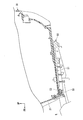
- FIG. 1 is a left side view of a motorcycle according to an embodiment.
- FIG. 1 is a left side view of a rear part of a motorcycle according to an embodiment. It is a front view of a storage box concerning an embodiment. It is a bottom view of the storage box concerning an embodiment. It is the perspective view which looked at the storage box which concerns on embodiment from lower left. It is the perspective view which looked at vehicles rear when a storage box concerning an embodiment is removed from a career from the lower left. It is the perspective view which looked at the carrier concerning an embodiment from upper left. It is the perspective view which looked at the carrier concerning an embodiment from the upper front. It is a bottom view of a career concerning an embodiment.
- FIG. 4 is a view including an XX cross section of FIG. 3; FIG.
- FIG. 4 is a view including a cross section taken along line XI-XI of FIG. 3;
- FIG. 4 is a view including the XII-XII cross section of FIG. 3;
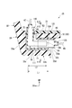
- It is the perspective view which looked at the electric power feeding part (terminal connection part) which concerns on embodiment from upper right.
- It is the perspective view which looked at the electric power feeding part (terminal connection part) which concerns on embodiment from upper left.
- FIG. 16 is a view including the XVI-XVI cross section of FIG. 15;
- FIG. 17 is a view including a XVII-XVII cross section of FIG.
- FIG. 16 It is a figure containing the cross section corresponded in FIG. 11 which shows the attachment state of the cover member which concerns on embodiment. It is a figure which shows the 1 process of the attachment procedure of the storage box which concerns on embodiment, and is a figure containing the cross section corresponded in FIG. It is a figure including the cross section corresponded in FIG. 15 which shows the electric power feeding part (terminal connection part) which concerns on the 1st modification of embodiment. It is a figure containing the cross section corresponded in FIG. 16 which shows the connection state of the electric power feeding part (terminal connection part) which concerns on the 1st modification of embodiment. It is a figure including the cross section corresponded in FIG.
- FIG. 15 which shows the electric power feeding part (terminal connection part) which concerns on the 2nd modification of embodiment. It is a figure containing the cross section corresponded in FIG. 16 which shows the connection state of the electric power feeding part (terminal connection part) which concerns on the 2nd modification of embodiment. It is a figure including the cross section corresponded in FIG. 16 which shows the connection state of the electric power feeding part (terminal connection part) which concerns on the 3rd modification of embodiment. It is a figure including the cross section corresponded in FIG. 15 which shows the electric power feeding part (terminal connection part) which concerns on the 4th modification of embodiment. It is a figure including the cross section corresponded in FIG. 17 which shows the electric power feeding part (terminal connection part) which concerns on the 4th modification of embodiment.
- FIG. 1 shows a unit swing type motorcycle 1 as an example of a straddle type vehicle.
- a motorcycle 1 includes a front wheel 3 steered by a steering wheel 2 and a rear wheel 4 driven by a power unit 5 including a power source.
- a motorcycle may be simply referred to as a "vehicle”.
- the motorcycle 1 of the embodiment is a scooter type vehicle having a step floor 9 on which a passenger seated on a seat 8 places a foot.
- Steering system components including the steering wheel 2 and the front wheel 3 are steerably supported by a head pipe (not shown) at the front end of the vehicle body frame.
- the outer periphery of the vehicle body frame is covered with a vehicle body cover 10.
- reference numeral 6 denotes a front fork.
- a bridging portion 21 having a relatively low vehicle height is provided between the steering wheel 2 and the seat 8.
- the step floor 9 is provided on the left and right sides of the crossing portion 21.
- a center tunnel 22 extending in the front-rear direction in a convex bulging shape.
- the body cover 10 includes a front center cover 11 covering the head pipe periphery from the front, left and right front side covers 12 covering the head pipe periphery from the front outer side, and a head pipe periphery covered from the rear and the front of the center tunnel 22 and left and right
- the front inner cover 14 that forms the footrest 13, the left and right floor front covers 15 that run below the left and right front side covers 12, the left and right floor side covers 16 that run below the left and right floor front covers 15, and the front inner cover 14
- a center upper cover 17 which is continuous with the lower rear portion to form a rear upper surface of the center tunnel 22, a left and right center side cover 18 which is continuous with the lower rear of the front inner cover 14 to form a rear side surface of the central tunnel 22, It includes left and right rear side covers 19 covering the rear portion of the vehicle body from the side continuous to the rear of Pakaba 17 and lateral center side covers 18.
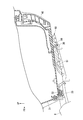
- a storage box feed structure 25 (see FIG. 15) is provided for feeding power to the electrical components provided in the storage box 30 or the like.
- the storage box feeding structure 25 includes a storage box 30, a carrier 50 capable of detachably mounting the storage box 30 on a vehicle body, and a hook 33 (front hook 33 shown in FIG. 5) capable of connecting the storage box 30 to the carrier 50.
- a hook receiving portion 53 (the front hook receiving portion 53 shown in FIG. 7) for receiving the hook 33, and a hook side provided inside the hook 33 for supplying power to the electric component 46 (the lid lamp 46 shown in FIG. 2)
- Terminals 70 (see FIG. 13) and receiving terminals 80 (see FIG. 13) provided in the hook receiving portion 53 and connected to the hook side terminals 70 when the storage box 30 is mounted on the carrier 50; Prepare.
- the storage box 30 is detachably attached to the carrier 50.
- the storage box 30 can store articles such as a helmet.
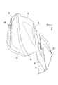
- the storage box 30 includes a box-like box main body 31 that opens upward, and a lid 32 provided on the top of the box main body 31 so as to be openable and closable.
- the box body 31 is opposed to the left and right front hooks 33 located at the front lower portion of the box body 31, the rear hook 34 located at the center of the rear lower portion of the box body 31, and the rear hooks 34.
- the pair of left and right front hooks 33 are arranged in line symmetry with the vehicle body left and right center line CL as the axis of symmetry.
- the reinforcing portions of the left and right front hooks 33 are fixed to the front lower portion of the box body 31 by fastening members such as bolts.
- the left and right front hooks 33 extend downward from the front lower portion of the box body 31 and then bend rearward to form an L-shape.
- the rear ends of the left and right front hooks 33 are inclined so as to be positioned more rearward in the vehicle width direction.
- the rear hook 34 is movable in conjunction with the turning operation of a key (not shown).
- the rear hook 34 is movable between an engagement position with respect to the rear hook receiving portion 54 and an engagement release position in conjunction with the operation of a rear hook locking mechanism (not shown) interlocked with the turning operation of the key.
- the rear hook 34 extends downward from the lower portion of the box body 31 and then bends rearward and forms an L-shape.
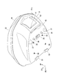
- the left and right side stoppers 36 and the left and right leg portions 37 project downward from the lower surface of the box body 31.
- the protruding heights of the left and right side stoppers 36 are respectively lower than the protruding heights of the left and right legs 37.
- the left and right side stoppers 36 function as load receiving portions that receive a load from the front-rear direction.
- the four elastic members 38 are disposed between the front and rear of the left and right front hooks 33 and the left and right side stoppers 36.
- the four elastic members 38 are spaced apart in the front-rear direction and the vehicle width direction.
- the elastic member 38 is a vibration-proof rubber.
- the handle 42 is swingably attached to the rear of the box body 31.
- the handle 42 In the state of FIG. 5, the handle 42 is in the storage state stored in the U-shaped groove 31 u. In the stored state, the handle 42 is disposed along the rear surface of the box body 31.
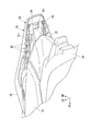
- the lid 32 is a box-like member that covers the box body 31 from above. As shown in FIG. 10, the lid 32 is swingably attached to the front end portion of the box body 31 via a swing shaft 45. The lid 32 can be locked by a lid locking mechanism (not shown).
- a lid lamp 46 as an electrical component is provided.
- the lid lamp 46 is a light emitting diode (LED: Light Emitting Diode).
- the lid lamp 46 is connected to the hook side terminal 70 (see FIG. 13) via a cord 47 (see FIG. 3) drawn around the inner surface of the lid 32.
- a portion 47a (see FIG. 3) closer to the front of the lid 32 of the cord 47 be disposed in parallel with the swing shaft 45 (see FIG. 10).
- the portion 47 b (see FIG. 3) of the cord 47 closer to the front of the box main body 31 be disposed along the inner wall of the corner of the box main body 31.
- the carrier 50 can detachably mount the storage box 30 on the vehicle body.
- the carrier 50 includes a carrier body 51 on which the storage box 30 is mounted, and a pair of left and right grab rails 52 for a passenger to hold.
- the carrier body 51 and the left and right grab rails 52 are integrally formed of the same member.
- the carrier main body 51 has an outer shape in which the width in the vehicle width direction is smaller toward the rear side.
- the left and right front hook receiving portions 53 (see FIG. 11) that receive the left and right front hooks 33 (see FIG. 5).
- a rear hook receiving portion 54 (see FIG. 10) receiving the rear hook 34 (see FIG. 5)
- a pair of left and right side insertion holes 56 (see FIG. 12)
- a seating surface 57 with which the elastic member 38 (see FIG. 5) abuts.
- the front portion of the carrier body 51 is provided with an upper and lower opening 51 h that opens in the vicinity of the front hook receiving portion 53.
- the upper and lower opening 51 h has an elongated hole shape extending so as to be positioned more rearward in the vehicle width direction.
- reference numeral 27 denotes a taillight
- reference numeral 28 denotes a rear fender.
- the carrier body 51 has a pair of left and right openings 51i which open the central portion of the carrier body 51 vertically and a front through hole 51m which opens the front of the carrier body 51 vertically. Is provided.
- the left and right openings 51i have an elongated hole shape extending in the front and rear direction.
- the front through hole 51 m has a circular shape.
- the front through hole 51m is a through hole through which a shaft portion of a bolt for fixing the carrier body 51 to the rear frame 7 (see FIG. 10) is inserted.
- the left and right grab rails 52 extend forward from the outer end in the vehicle width direction of the front portion of the carrier body 51.
- the upper end edges of the left and right grab rails 52 are inclined so as to be positioned lower toward the front side.
- the left and right grab rails 52 are provided with inward protruding portions 52 a that project inward in the vehicle width direction from the front end portions of the left and right grab rails 52.
- the inward protrusion 52a is fixed to the rear frame 7 (see FIG. 10) by a fastening member (not shown) such as a bolt.
- a plurality of ribs 61 to 66 are provided at the lower part of the carrier 50.
- the plurality of ribs 61 to 66 extend in the longitudinal direction so as to cross the formation portion of the front through hole 51m and the rear hook receiving portion 54, the formation portion of the front through hole 51m, and the vehicle width of the carrier main body 51
- a second rib 62 extending in the vehicle width direction so as to cross the direction outer end edge, a third rib 63 extending so as to cross the left and right front hook receiving portions 53 and the second rib 62, and a forming portion of the side insertion hole 56 And the second rib 62, and a fifth rib 65 extending from the outer edge of the left and right openings 51i in the vehicle width direction to the outer edge of the carrier main body 51 in the vehicle width direction.
- the sixth rib 66 extends in the vehicle width direction at the front lower portion of the left and right grab rails 52.
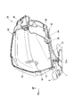
- the front hooks 33 are provided on the storage box 30 side.
- the front hook 33 extends downward from the front lower portion of the box body 31 and then bends and extends rearward to form an L-shape.
- the front hook 33 has a lower extension 33a extending downward from the front lower portion of the storage box 30 (see FIG. 11) and a rear extending rearward from the lower end of the lower extension 33a. And an extending portion 33 b (front and rear extending portion).
- the rear extension 33b has a box shape having a U-shaped cross section (see FIG. 16) that opens upward.
- the rear extension portion 33 b of the front hook 33 is provided with a space capable of accommodating the front and rear extension case portion 111 of the hook side case 110.
- the hook side terminal 70 is integrally provided in the rear extension part 33b via the hook side case 110.
- the rear extension 33 b includes a lower wall 33 c covering the hook side terminal 70 from below and a vertical wall 33 d covering the left and right hook side terminals 70 from the outside in the vehicle width direction.
- the vertical wall portion 33 d extends above the hook-side terminal 70. The upper end of the vertical wall portion 33 d abuts on the lower surface of the carrier 50 when the storage box 30 is mounted on the carrier 50.
- the hook side terminal 70 is provided inside the front hook 33.
- the hook side terminal 70 is attached to the front hook 33 via the hook side case 110.
- the hook-side terminals 70 are disposed at a pair of left and right intervals.
- the hook side terminals 70 are provided on each of the left and right front hooks 33.
- the hook side terminal 70 has an L shape extending along the front hook 33.
- the hook side terminal 70 is a male terminal.
- a part of the hook side terminal 70 has a plate shape extending in the extending direction of the rear extending portion 33 b.
- the hook side terminal 70 includes a front and rear extension 71 extending longitudinally along the rear extension 33b of the front hook 33, and an upper extension 72 extending upward from the front end of the front and rear extension 71. And.
- the tip end 70 t of the hook side terminal 70 is located inside the tip 33 t of the front hook 33.
- the front end 70t of the hook side terminal 70 corresponds to the rear end of the front and rear extension 71
- the front end 33t of the front hook 33 corresponds to the rear end of the vertical wall 33d. That is, the rear end of the front and rear extending portion 71 is located forward of the rear end of the vertical wall portion 33 d.
- the upper end of the vertically extending portion 72 is located above the upper end of the front hook 33.
- One end of a cord 47 is connected to the upper end of the vertically extending portion 72.
- the other end of the cord 47 is connected to the lid lamp 46 (see FIG. 5).
- a hook side case 110 that encloses the hook side terminal 70 is provided inside the front hook 33.
- the hook side case 110 has an L shape extending along the hook side terminal 70.
- the hook case 110 is attached to the front hook 33 via a seal member 69.
- the hook side case 110 includes a front and rear extending case portion 111 extending in the longitudinal direction along the front and rear extending portion 71 of the hook side terminal 70, and an upper extension extending upward from the front end of the front and rear extending case portion 111.
- the front-rear length L1 of the front-rear extending case portion 111 in the hook side case 110 is taken as “front-rear length L1 of the hook side case 110”.
- the front-rear length L2 of the front-rear extending portion 71 of the hook side terminal 70 is referred to as “front-rear length L2 of the hook side terminal 70”.
- the longitudinal length L2 of the hook side terminal 70 is shorter than the longitudinal length L1 of the hook side case 110 (L2 ⁇ L1).
- the front and rear extension case portion 111 includes a hook terminal lower covering portion 113 covering the hook side terminal 70 from below and a hook terminal side covering portion covering the left and right hook side terminals 70 from the outer side in the vehicle width direction. And a pair of left and right hook terminal-side vertical wall portions 115 that divide the housing space of the left and right hook-side terminals 70 in the vehicle width direction.
- the hook terminal side cover portion 114 and the hook terminal side vertical wall portion 115 extend in the front and back direction along the front and rear extension portions 71 of the hook side terminal 70.
- the hook terminal side cover portion 114 and the hook terminal side vertical wall portion 115 extend rearward of the front and rear extension portions 71 of the hook side terminal 70.
- the hook terminal side cover portion 114 and the hook terminal side vertical wall portion 115 extend above the front and rear extension portions 71 of the hook side terminal 70.
- the pair of left and right hook terminal side covering portions 114 are separated in the vehicle width direction so as to be able to receive the receiving case 120.
- the separation distance between the pair of left and right hook terminal side cover portions 114 is equal to or greater than the length in the vehicle width direction of the receiving case 120.
- the pair of left and right hook terminal side vertical wall portions 115 are separated in the vehicle width direction so as to be able to receive the partition wall 124 of the receiving case 120.
- the separation distance between the pair of left and right hook terminal-side vertical wall portions 115 is equal to or larger than the width of the partition wall 124 of the receiving case 120.
- the front hook receiving portion 53 is a portion of the front portion of the carrier main body 51 that faces the upper and lower opening 51 h (see FIG. 7) from above.
- the front hook receiving portion 53 is a portion that receives a load when the storage box 30 is mounted on the carrier 50.
- the front hook receiving portion 53 has a thickness that can enter between the bottom of the storage box 30 (box main body 31) and the top end of the front hook 33.
- a rear opening 53h for opening the rear extension 33b (see FIG. 15) of the front hook 33 from the front to the rear. There is.
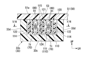
- the receiving side terminal 80 is provided in the front hook receiving portion 53. As shown in FIG. 16, the receiving terminal 80 is provided on the lower surface side of the carrier 50. As shown in FIG. 17, the receiving terminal 80 is a female terminal.
- the receiving side terminal 80 includes a pair of terminal pieces 81 sandwiching the hook side terminal 70. One pair of terminal pieces 81 is provided in each accommodation space. The pair of terminal pieces 81 oppose each other in the vehicle width direction.
- the pair of terminal pieces 81 extend in the front-rear direction.
- the front end portions of the pair of terminal pieces 81 are inclined so as to be positioned outward in the vehicle width direction toward the front side.
- the hook side terminal 70 can be easily introduced between the pair of terminal pieces 81.
- convex portions 81a that protrude toward the hook side terminals 70 are provided.
- the convex portion 81 a has an arc shape that is convex toward the hook side terminal 70. That is, the contact part of the hook side terminal 70 and the convex part 81a becomes a contact part of the terminals 70 and 80.
- the rear ends of the pair of terminal pieces 81 are connected to each other.
- the rear ends of the pair of terminal pieces 81 are located rearward of the rear end (receiving terminal rear cover portion 123) of the receiving case 120.
- the rear ends of the pair of terminal pieces 81 are connected to a battery (not shown) on the vehicle body side via a wire 85 (see FIG. 14).
- the hook receiving portion 53 is provided with a receiving case 120 surrounding the receiving terminal 80.
- the receiving case 120 is in the form of a box whose front and lower sides are open.
- the receiving case 120 is attached to the lower surface of the carrier 50 (the top wall 51a). That is, the receiving case 120 is attached to the lower surface of the front hook receiving portion 53.
- the receiving side case 120 includes a receiving terminal upper covering part 121 covering the receiving side terminal 80 from above, and a receiving terminal side covering part 122 covering the receiving side terminal 80 from the outside in the vehicle width direction; And a receiving terminal rear cover portion 123 covering the receiving terminal 80 from the rear side.
- a partition wall 124 extending downward from the receiving terminal upper cover portion 121 and an outward projecting portion 125 protruding outward in the vehicle width direction from the receiving terminal upper cover portion 121. And are provided.
- the partition wall 124 extends back and forth along the receiving terminal side cover portion 122.
- the partition wall 124 divides the housing space of the receiving side terminal 80 in the vehicle width direction.
- the outward protrusion 125 is fixed to the carrier 50 (see FIG. 11) by a fastening member (not shown) such as a bolt.
- the receiving side terminal 80 (see FIG. 15) on the carrier 50 side and the hook side terminal 70 (see FIG. 15) on the storage box 30 side are connected.
- Ru Specifically, as shown in FIG. 17, by connecting the hooks 33 to the hook receiving portion 53 (see FIG. 15), the convex portions 81a of the pair of terminal pieces 81 and the hook side terminals 70 are connected. As a result, power can be supplied from the battery (not shown) on the vehicle body side to the electric component (lid lamp 46 shown in FIG. 5) on the lid 32 side.
- the storage box feeding structure 25 is detachably provided on the carrier 50, and a lid that covers the front hook receiving portion 53 when the storage box 30 (see FIG. 2) is not mounted on the carrier 50.
- a member 90 may further be provided.
- the lid member 90 is continuous with the upper wall 91 covering the upper and lower opening 51 h from above, the front wall 92 covering the rear opening 53 h from the front, and the upper wall 91, and the ceiling 51 a of the carrier body 51.
- the upper engagement piece 93 engaged with the front end (the lower surface of the front hook receiving portion 53), and the front engagement piece 94 connected with the front wall 92 and engaged with the claw portion 51b of the carrier main body 51.
- the storage box feeding structure 25 of the above embodiment enables the storage box 30, the carrier 50 capable of detachably mounting the storage box 30 on the vehicle body, and the storage box 30 to be connectable to the carrier 50.
- the hook 33, the hook receiving portion 53 for receiving the hook 33, and the hook side terminal 70 provided inside the hook 33 for supplying power to the lid lamp 46 and the hook receiving portion 53, and the storage box 30 is the carrier 50.
- the hooks 33 are hooked on the hook receiving portions 53, so that the terminals 70 and 80 can be supported rigidly.
- the feed structure is provided inside the hooks 33, it is not necessary to provide a new feed section at the bottom of the storage box 30, and it is not necessary to greatly change the shapes of the storage box 30 and the carrier 50. Therefore, without providing a new feeding portion in the storage box 30, a feeding structure using an existing structure can be provided, and the feeding portion can be provided at a portion that is resistant to vibration and high in rigidity.
- the friction when attaching the hook 33 to the hook receiving portion 53 can perform self cleaning of the terminals 70 and 80.
- the oxide film on the terminals 70 and 80 can be removed, or foreign matter such as sand bite can be removed.
- the hook side terminal 70 is less likely to be exposed to the outside. Therefore, foreign substances such as dust are less likely to adhere to the hook side terminal 70, so that the contact reliability of the terminals 70 and 80 can be maintained.
- the hook 33 is integrally provided with the hook side terminal 70, and the following effects can be obtained by providing the rear extension portion 33b extending in the front-rear direction.
- a sliding operation in the front-rear direction can be applied to the rear extension portion 33b. Therefore, while being able to stabilize the connection of the terminals 70 and 80, the sand biting of a contact part can be prevented.
- the rear extension 33b extends upward above the hook-side terminal 70, and the vertical wall 33d contacts the lower surface of the carrier 50 when the storage box 30 is mounted on the carrier 50.
- the upper end of the vertical wall portion 33 d and the lower surface of the carrier 50 serve as a load receiving portion, so that it is possible to avoid applying a load to the power feeding portion.
- the hook-side terminal 70 is a male terminal, and a part of the hook-side terminal 70 has a plate shape extending in the extending direction of the rear extension portion 33 b.
- the side terminal 70 can absorb deflection in the vehicle width direction. Therefore, while absorbing the variation in the connection position of the terminals 70 and 80, the power feeding portion can be provided at a portion that is resistant to vibration.
- the hook side terminal 70 can make a sliding movement in the front-rear direction. Therefore, while being able to stabilize the connection of the terminals 70 and 80, the sand biting of a contact part can be prevented.
- the tip 70t of the hook side terminal 70 is positioned inside the tip 33t of the hook 33, the hook 33 and the hook receiving portion 53 are positioned, and then the hook side terminal 70 and the receiving side terminal And 80 are connected. Therefore, when the terminal on the storage box 30 side and the terminal on the carrier 50 side are connected, positioning of the terminal can be easily performed.
- the hook side case 110 covering the hook side terminal 70 is provided inside the hook 33, and the longitudinal length L2 of the hook side terminal 70 is shorter than the longitudinal length L1 of the hook side case 110
- the hook side terminal 70 and the receiving side terminal 80 are connected. Therefore, when the terminal on the storage box 30 side and the terminal on the carrier 50 side are connected, positioning of the terminal can be easily performed.
- the receiving side terminal 80 can be rigidly supported by the receiving side terminal 80 being positioned on the lower surface side of the carrier 50.
- the receiving side terminal 80 is a female terminal, and by providing the pair of terminal pieces 81 sandwiching the hook side terminal 70, the following effects can be obtained. Compared with the case where the receiving side terminal 80 includes only one terminal piece 81, the hook side terminal 70 and the receiving side terminal 80 can be connected reliably.
- the pair of terminal pieces 81 since the pair of terminal pieces 81 oppose each other in the vehicle width direction, the pair of terminal pieces 81 can absorb deflection in the vertical direction. Therefore, while absorbing the variation in the connection position of the terminals 70 and 80, the power feeding portion can be provided at a portion that is resistant to vibration.
- the hook receiving portion 53 is provided with the receiving case 120 in the form of a box that encloses the receiving side terminal 80 and is opened at the lower side. Is less likely to be exposed to the outside.
- the lower surface side of the hook receiving portion 53 is provided with a rear opening portion 53h for opening the rear extending portion 33b of the hook 33 so as to be able to be received from the front. Play.
- the hook 33 can be easily approached with respect to the hook receiving portion 53 as compared with the case where the hook receiving portion 53 can receive the hook 33 from the rear.
- the carrier 50 is a rear carrier 50 provided at the rear of the vehicle body
- the storage box 30 can be easily mounted on the rear carrier 50.
- the carrier 50 is provided with the upper and lower openings 51 h that open vertically in the vicinity of the hook receiving portion 53, so that water can be drained through the openings of the upper and lower openings 51 h. For example, even when the storage box 30 is mounted on the carrier 50 when it is raining, rainwater and the like can be prevented from entering the hook receiving portion 53.
- the cover member 90 is provided so as to be detachable from the carrier 50 and further to cover the hook receiving portion 53 when the storage box 30 is not mounted on the carrier 50.
- the receiving portion 53 is not exposed to the outside. Therefore, when the storage box 30 is not mounted on the carrier 50, foreign matter such as water and dust can be prevented from entering the hook receiving portion 53.
- the following effects are show
- the storage box 30 may be provided at the front of the vehicle or at the side of the vehicle (the side of the carrier 50).
- the front hook 33 extends downward from the front lower portion of the box body 31 and then bends and extends backward to form an L-shape.
- the present invention is not limited to this.
- the front hook 33 may have an L-shape extending downward from the lower front of the box body 31 and then bent forward.
- the hook side terminal 70 is provided inside the front hook 33, it does not restrict to this.
- the hook side terminal 70 may be provided inside the rear hook 34.
- the hook side terminal 70 is provided in each of the left and right front hooks 33, it does not restrict to this.
- the hook side terminal 70 may be provided only on one of the left and right front hooks 33. That is, the hook side terminal 70 may be provided on at least one of the left and right front hooks 33.
- front hook 33 was provided by one pair on the left and right, it does not restrict to this.
- only one front hook 33 may be provided, or a plurality of three or more front hooks may be provided.
- the said embodiment mentioned the example which the outward protrusion part 125 in the front hook receiving part 53 is being fixed to the carrier 50 by fastening members (not shown), such as a volt
- the front hook receiving portion 53 may be integrally formed on the carrier 50.
- all of the hook side terminals 70 may have a plate shape extending in the extending direction of the rear extending portion 33b. That is, at least a part of the hook side terminal 70 may have a plate shape extending in the extending direction of the rear extending portion 33b.
- the said embodiment gave and demonstrated the example which the hook side case 110 is attached to the front hook 33 via the sealing member 69, it does not restrict to this.
- the hook case 110 may be directly fixed to the front hook 33.
- the pair of left and right hook terminal side cover parts 114 are separated in the vehicle width direction so as to be able to receive the receiving side case 120 , but the present invention is not limited thereto.
- the pair of left and right hook terminal side cover parts 114 may have a size that fits between the receiving side case 120 in the vehicle width direction. That is, in the vehicle width direction, the separation distance between the pair of left and right receiving terminal side cover parts 122 may have a size equal to or greater than the length in the vehicle width direction of the hook side case 110.
- the said embodiment gave and demonstrated the example which the receiving side case 120 is attached to the lower surface of the front hook receiving part 53, it does not restrict to this.
- the receiving case 120 may be incorporated in the front hook receiving portion 53.
- the pair of left and right hook terminal side covering portions 114 fits between the vehicle width direction of the receiving case 120. It may have a size.
- two receiving side cases 120A may be provided to surround one receiving side terminal 80 (a pair of terminal pieces 81).
- the front hook 33 includes the lower wall 33c covering the hook side terminal 70 from below and the vertical wall 33d covering the left and right hook side terminals 70 from the outside in the vehicle width direction.
- the front hook 33 further includes a second vertical wall 33e that divides the housing space of the receiving terminals 80 in the vehicle width direction. May be The second vertical wall 33 e may abut on the lower surface of the carrier 50 together with the left and right vertical walls 33 d when the storage box 30 is mounted on the carrier 50.
- Reference numeral 110A in FIG. 24 denotes a hook side case corresponding to each receiving side case 120.
- the said embodiment gave and demonstrated the example which the hook side terminal 70 is attached to the front hook 33 via the hook side case 110, it does not restrict to this.
- the hook side terminal 70 may be directly attached to the front hook 33. That is, the hook side case 110 may not be provided inside the front hook 33.
- the rear extension 33b of the front hook 33 is described as having an example in which a space capable of accommodating the front and rear extension case 111 of the hook side case 110 is provided. Not exclusively.
- the rear extension 33b of the front hook 33 is provided with a space 129 which can accommodate a portion of the front hook receiving portion 53 (see FIG. 25) containing the receiving case 120. May be
- the lid lamp 46 was mentioned as an example and demonstrated as an electrically-wired part, it does not restrict to this.
- the electrical components may be other electrical components such as a USB charger and a solenoid, or may be other lighting devices other than the lid lamp 46.
- the straddle-type vehicle includes all vehicles on which the driver straddles the vehicle body, and includes a motorcycle (motorized bicycle and scooter type vehicle Not only vehicles with three wheels (including one wheel and two wheels, but also two wheels and one wheel) are included.
- the present invention is applicable not only to motorcycles but also to four-wheeled vehicles such as automobiles.
- the configuration in the above embodiment is an example of the present invention, and various modifications can be made without departing from the scope of the present invention, such as replacing the components of the embodiment with known components.
Landscapes
- Engineering & Computer Science (AREA)
- Mechanical Engineering (AREA)
- Battery Mounting, Suspending (AREA)
- Automatic Cycles, And Cycles In General (AREA)
Abstract
この鞍乗型車両の収納ボックス給電構造は、収納ボックス(30)と、前記収納ボックス(30)を車体に着脱自在に搭載可能なキャリア(50)と、前記収納ボックス(30)を前記キャリア(50)に接続可能とするフック(33)と、前記フック(33)を受けるフック受け部(53)と、前記フック(33)の内側に設けられ、電装部品(46)に給電するためのフック側端子(70)と、前記フック受け部(53)に設けられ、前記収納ボックス(30)が前記キャリア(50)に搭載されたときに、前記フック側端子(70)に接続される受け側端子(80)と、を備える。
Description
本発明は、鞍乗型車両の収納ボックス給電構造に関する。
本願は、2017年12月28日に、日本に出願された特願2017-254999号に基づき優先権を主張し、その内容をここに援用する。
本願は、2017年12月28日に、日本に出願された特願2017-254999号に基づき優先権を主張し、その内容をここに援用する。
従来、鞍乗型車両の収納ボックス給電構造において、内部に電装部品を有する収納ボックスと、収納ボックスを車体に着脱自在に搭載可能なキャリアと、を備えたものが開示されている(例えば特許文献1参照)。収納ボックスをキャリアに取り付けることにより、キャリア側コネクタと収納ボックス側コネクタとが接続され、車両のバッテリから電装部品に給電可能な状態となる。
しかしながら、特許文献1では、給電構造とするために、収納ボックスの底部(キャリア側対向部と対向するボックス側対向部)に、新たな給電部(ボックス側コネクタ)を設けており、収納ボックスおよびキャリアの形状を大きく変更する必要がある。また、収納ボックス側の端子とキャリア側の端子との接触部分(以下「接点部」という。)に振動が入ることが予想される。
そこで本発明は、鞍乗型車両の収納ボックス給電構造において、収納ボックスに新たな給電部を設けることなく、既存の構造を利用した給電構造とし、振動に強く、剛性の高い部位に給電部を設けることを目的とする。
上記課題の解決手段として、本発明の態様は以下の構成を有する。
(1)本発明の態様に係る鞍乗型車両の収納ボックス給電構造は、収納ボックス(30)と、前記収納ボックス(30)を車体に着脱自在に搭載可能なキャリア(50)と、前記収納ボックス(30)を前記キャリア(50)に接続可能とするフック(33)と、前記フック(33)を受けるフック受け部(53)と、前記フック(33)の内側に設けられ、電装部品(46)に給電するためのフック側端子(70)と、前記フック受け部(53)に設けられ、前記収納ボックス(30)が前記キャリア(50)に搭載されたときに、前記フック側端子(70)に接続される受け側端子(80)と、を備える。
(1)本発明の態様に係る鞍乗型車両の収納ボックス給電構造は、収納ボックス(30)と、前記収納ボックス(30)を車体に着脱自在に搭載可能なキャリア(50)と、前記収納ボックス(30)を前記キャリア(50)に接続可能とするフック(33)と、前記フック(33)を受けるフック受け部(53)と、前記フック(33)の内側に設けられ、電装部品(46)に給電するためのフック側端子(70)と、前記フック受け部(53)に設けられ、前記収納ボックス(30)が前記キャリア(50)に搭載されたときに、前記フック側端子(70)に接続される受け側端子(80)と、を備える。
(2)上記(1)に記載の鞍乗型車両の収納ボックス給電構造では、前記フック(33)は、前記フック側端子(70)が一体に設けられ、前後方向に延出する前後延出部(33b)を備えてもよい。
(3)上記(2)に記載の鞍乗型車両の収納ボックス給電構造では、前記前後延出部(33b)は、前記フック側端子(70)よりも上方に延出し、前記収納ボックス(30)が前記キャリア(50)に搭載されたときに、前記キャリア(50)の下面に当接する縦壁部(33d)を備えてもよい。
(4)上記(2)または(3)に記載の鞍乗型車両の収納ボックス給電構造では、前記フック側端子(70)は、雄端子であり、前記フック側端子(70)の少なくとも一部は、前記前後延出部(33b)の延出方向に延出する板状をなしてもよい。
(5)上記(1)から(4)のいずれか一項に記載の鞍乗型車両の収納ボックス給電構造では、前記フック側端子(70)の先端(70t)は、前記フック(33)の先端(33t)よりも内側に位置してもよい
(6)上記(1)から(5)のいずれか一項に記載の鞍乗型車両の収納ボックス給電構造では、前記フック(33)の内側には、前記フック側端子(70)を囲うフック側ケース(110)が設けられ、前記フック側端子(70)の前後長さ(L2)は、前記フック側ケース(110)の前後長さ(L1)よりも短くてもよい。
(7)上記(1)から(6)のいずれか一項に記載の鞍乗型車両の収納ボックス給電構造では、前記受け側端子(80)は、前記キャリア(50)の下面側に位置してもよい。
(8)上記(1)から(7)のいずれか一項に記載の鞍乗型車両の収納ボックス給電構造では、前記受け側端子(80)は、雌端子であり、前記フック側端子(70)を挟む一対の端子片(81)を備えてもよい。
(9)上記(8)に記載の鞍乗型車両の収納ボックス給電構造では、前記一対の端子片(81)は、車幅方向に対向してもよい。
(10)上記(1)から(9)のいずれか一項に記載の鞍乗型車両の収納ボックス給電構造では、前記フック受け部(53)には、前記受け側端子(80)を囲い、下方が開口した箱状をなす受け側ケース(120)が設けられてもよい。
(11)上記(10)に記載の鞍乗型車両の収納ボックス給電構造では、前記フック(33)は、前記収納ボックス(30)の下部から下方に延出する下方延出部(33a)と、前記下方延出部(33a)の下端から後方に延出する後方延出部(33b)と、を備え、前記フック受け部(53)の下面側には、前記後方延出部(33b)を前方から受け入れ可能に後方に開口する後方開口部(53h)が設けられてもよい。
(12)上記(1)から(11)のいずれか一項に記載の鞍乗型車両の収納ボックス給電構造では、前記キャリア(50)には、前記フック受け部(53)の近傍で上下に開口する上下開口部(51h)が設けられてもよい。
(13)上記(1)から(12)のいずれか一項に記載の鞍乗型車両の収納ボックス給電構造では、前記キャリア(50)に着脱可能に設けられ、前記収納ボックス(30)が前記キャリア(50)に搭載されていないときに、前記フック受け部(53)を覆う蓋部材(90)を更に備えてもよい。
(14)上記(1)から(13)のいずれか一項に記載の鞍乗型車両の収納ボックス給電構造では、前記フック(33)は、左右に一対設けられてもよい。
本発明の上記(1)に記載の鞍乗型車両の収納ボックス給電構造によれば、フックの内側に設けられ、電装部品に給電するためのフック側端子と、フック受け部に設けられ、収納ボックスがキャリアに搭載されたときに、フック側端子に接続される受け側端子と、を備えることで、以下の効果を奏する。フックがフック受け部に引っ掛けられることで、剛性をもって端子を支持することができる。加えて、フックの内側に給電構造を設けるため、収納ボックスの底部に新たな給電部を設ける必要がなく、収納ボックスおよびキャリアの形状を大きく変更する必要もない。したがって、収納ボックスに新たな給電部を設けることなく、既存の構造を利用した給電構造とし、振動に強く、剛性の高い部位に給電部を設けることができる。
加えて、フックをフック受け部に取り付けるときの摩擦によって、端子のセルフクリーニングを行うことができる。例えば、端子の酸化被膜を除去したり、砂噛み等の異物を除去したりすることができる。
加えて、フック側端子がフックの内側に設けられることで、フック側端子が外部に露出しにくくなる。したがって、フック側端子に塵埃などの異物が付着しにくくなるため、端子の接触信頼性を保持することができる。
加えて、フックをフック受け部に取り付けるときの摩擦によって、端子のセルフクリーニングを行うことができる。例えば、端子の酸化被膜を除去したり、砂噛み等の異物を除去したりすることができる。
加えて、フック側端子がフックの内側に設けられることで、フック側端子が外部に露出しにくくなる。したがって、フック側端子に塵埃などの異物が付着しにくくなるため、端子の接触信頼性を保持することができる。
本発明の上記(2)に記載の鞍乗型車両の収納ボックス給電構造によれば、フックは、フック側端子が一体に設けられ、前後方向に延出する前後延出部を備えることで、以下の効果を奏する。フックをフック受け部に取り付けるときに、前後延出部において前後方向のスライド動作を作用させることができる。したがって、端子の接続を安定させるとともに、接点部の砂噛みを防止することができる。
本発明の上記(3)に記載の鞍乗型車両の収納ボックス給電構造によれば、前後延出部は、フック側端子よりも上方に延出し、収納ボックスがキャリアに搭載されたときに、キャリアの下面に当接する縦壁部を備えることで、以下の効果を奏する。縦壁部の上端とキャリアの下面とが荷重の受け部となるため、給電部に負荷がかかることを回避することができる。
本発明の上記(4)に記載の鞍乗型車両の収納ボックス給電構造によれば、フック側端子は、雄端子であり、フック側端子の少なくとも一部は、前後延出部の延出方向に延出する板状をなしていることで、フック側端子によって車幅方向のたわみを吸収することができる。したがって、端子の接続位置のバラツキを吸収するとともに、振動に強い部位に給電部を設けることができる。
加えて、フックをフック受け部に取り付けるときに、フック側端子において前後方向のスライド動作を作用させることができる。したがって、端子の接続を安定させるとともに、接点部の砂噛みを防止することができる。
加えて、フックをフック受け部に取り付けるときに、フック側端子において前後方向のスライド動作を作用させることができる。したがって、端子の接続を安定させるとともに、接点部の砂噛みを防止することができる。
本発明の上記(5)に記載の鞍乗型車両の収納ボックス給電構造によれば、フック側端子の先端がフックの先端よりも内側に位置することで、フックとフック受け部とが位置決めされてからフック側端子と受け側端子とが接続される。したがって、収納ボックス側の端子とキャリア側の端子とを接続する場合、端子の位置決めを容易に行うことができる。
本発明の上記(6)に記載の鞍乗型車両の収納ボックス給電構造によれば、フックの内側には、フック側端子を覆うフック側ケースが設けられ、フック側端子の前後長さがフック側ケースの前後長さよりも短いことで、フック側ケースが位置決めされてからフック側端子と受け側端子とが接続される。したがって、収納ボックス側の端子とキャリア側の端子とを接続する場合、端子の位置決めを容易に行うことができる。
本発明の上記(7)に記載の鞍乗型車両の収納ボックス給電構造によれば、受け側端子がキャリアの下面側に位置することで、剛性をもって受け側端子を支持することができる。
本発明の上記(8)に記載の鞍乗型車両の収納ボックス給電構造によれば、受け側端子は、雌端子であり、フック側端子を挟む一対の端子片を備えることで、以下の効果を奏する。受け側端子が一つの端子片のみを備える場合と比較して、フック側端子と受け側端子との接続を確実に行うことができる。
本発明の上記(9)に記載の鞍乗型車両の収納ボックス給電構造によれば、一対の端子片が車幅方向に対向していることで、一対の端子片によって上下方向のたわみを吸収することができる。したがって、端子の接続位置のバラツキを吸収するとともに、振動に強い部位に給電部を設けることができる。
本発明の上記(10)に記載の鞍乗型車両の収納ボックス給電構造によれば、フック受け部には、受け側端子を囲い、下方が開口した箱状をなす受け側ケースが設けられていることで、受け側ケースによって受け側端子が外部に露出しにくくなる。
本発明の上記(11)に記載の鞍乗型車両の収納ボックス給電構造によれば、フック受け部の下面側には、フックの後方延出部を前方から受け入れ可能に後方に開口する後方開口部が設けられていることで、以下の効果を奏する。フック受け部がフックを後方から受け入れ可能とされた場合と比較して、フック受け部に対するフックのアプローチを容易に行うことができる。例えば、キャリアが車体後部に設けられたリアキャリアである場合、収納ボックスをリアキャリアに容易に搭載することができる。
本発明の上記(12)に記載の鞍乗型車両の収納ボックス給電構造によれば、キャリアには、フック受け部の近傍で上下に開口する上下開口部が設けられていることで、上下開口部の開口を通じて水抜きを行うことができる。例えば、雨が降っているときに収納ボックスをキャリアに搭載する場合でも、雨水などがフック受け部に入り込むことを回避することができる。
本発明の上記(13)に記載の鞍乗型車両の収納ボックス給電構造によれば、キャリアに着脱可能に設けられ、収納ボックスがキャリアに搭載されていないときに、フック受け部を覆う蓋部材を更に備えることで、蓋部材によってフック受け部が外部に露出することがなくなる。したがって、収納ボックスがキャリアに搭載されていないときに、水および塵埃などの異物がフック受け部に入り込むことを回避することができる。
本発明の上記(14)に記載の鞍乗型車両の収納ボックス給電構造によれば、フックが左右に一対設けられていることで、以下の効果を奏する。収納ボックスとキャリアとが左右でバランスよく接続されるため、フックが一つのみ設けられている場合と比較して、振動により強い部位に給電部を設けることができる。
以下、本発明の実施形態について図面を参照して説明する。なお、以下の説明における前後左右等の向きは、特に記載が無ければ以下に説明する車両における向きと同一とする。また以下の説明に用いる図中適所には、車両前方を示す矢印FR、車両左方を示す矢印LH、及び車両上方を示す矢印UPが示されている。また、図中符号CLは、車体左右中心線を示す。
<車両全体>
図1は、鞍乗型車両の一例としてのユニットスイング式の自動二輪車1を示す。図1を参照し、自動二輪車1は、ハンドル2によって操向される前輪3と、動力源を含むパワーユニット5によって駆動される後輪4と、を備える。以下、自動二輪車を単に「車両」ということがある。実施形態の自動二輪車1は、シート8に着座した乗員が足を載せるステップフロア9を有するスクータ型の車両である。
図1は、鞍乗型車両の一例としてのユニットスイング式の自動二輪車1を示す。図1を参照し、自動二輪車1は、ハンドル2によって操向される前輪3と、動力源を含むパワーユニット5によって駆動される後輪4と、を備える。以下、自動二輪車を単に「車両」ということがある。実施形態の自動二輪車1は、シート8に着座した乗員が足を載せるステップフロア9を有するスクータ型の車両である。
ハンドル2及び前輪3を含むステアリング系部品は、車体フレーム前端のヘッドパイプ(不図示)に操向可能に枢支されている。車体フレームの外周は車体カバー10で覆われている。図1において、符号6はフロントフォークを示す。
ハンドル2とシート8との間には、比較的車高が低い跨ぎ部21が設けられている。ステップフロア9は、跨ぎ部21の左右両側に設けられている。左右ステップフロア9の間には、上方に凸の膨出形状をなして前後に延びるセンタートンネル22が設けられている。
車体カバー10は、ヘッドパイプ周りを前方から覆うフロントセンターカバー11と、ヘッドパイプ周りを前外側方から覆う左右フロントサイドカバー12と、ヘッドパイプ周りを後方から覆うとともにセンタートンネル22の前部及び左右フットレスト13を形成するフロントインナーカバー14と、左右フロントサイドカバー12の後下方に連なる左右フロアフロントカバー15と、左右フロアフロントカバー15の下部後方に連なる左右フロアサイドカバー16と、フロントインナーカバー14の下部後方に連なりセンタートンネル22の後部上面を形成するセンターアッパーカバー17と、フロントインナーカバー14の下部後方に連なりセンタートンネル22の後部側面を形成する左右センターサイドカバー18と、センターアッパーカバー17及び左右センターサイドカバー18の後方に連なり車体後部を側方から覆う左右リヤサイドカバー19と、を備える。
<収納ボックス給電構造>
図1に示すように、車両後部には、収納ボックス30などに設けられた電装部品に給電するための収納ボックス給電構造25(図15参照)が設けられている。収納ボックス給電構造25は、収納ボックス30と、収納ボックス30を車体に着脱自在に搭載可能なキャリア50と、収納ボックス30をキャリア50に接続可能とするフック33(図5に示すフロントフック33)と、フック33を受けるフック受け部53(図7に示すフロントフック受け部53)と、フック33の内側に設けられ、電装部品46(図2に示すリッドランプ46)に給電するためのフック側端子70(図13参照)と、フック受け部53に設けられ、収納ボックス30がキャリア50に搭載されたときに、フック側端子70に接続される受け側端子80(図13参照)と、を備える。
図1に示すように、車両後部には、収納ボックス30などに設けられた電装部品に給電するための収納ボックス給電構造25(図15参照)が設けられている。収納ボックス給電構造25は、収納ボックス30と、収納ボックス30を車体に着脱自在に搭載可能なキャリア50と、収納ボックス30をキャリア50に接続可能とするフック33(図5に示すフロントフック33)と、フック33を受けるフック受け部53(図7に示すフロントフック受け部53)と、フック33の内側に設けられ、電装部品46(図2に示すリッドランプ46)に給電するためのフック側端子70(図13参照)と、フック受け部53に設けられ、収納ボックス30がキャリア50に搭載されたときに、フック側端子70に接続される受け側端子80(図13参照)と、を備える。
<収納ボックス>
図10に示すように、収納ボックス30は、キャリア50に着脱可能に取り付けられている。収納ボックス30は、ヘルメット等の物品を収納可能である。収納ボックス30は、上方に開口する箱状をなすボックス本体31と、ボックス本体31の上部に開閉可能に設けられたリッド32と、を備える。
図10に示すように、収納ボックス30は、キャリア50に着脱可能に取り付けられている。収納ボックス30は、ヘルメット等の物品を収納可能である。収納ボックス30は、上方に開口する箱状をなすボックス本体31と、ボックス本体31の上部に開閉可能に設けられたリッド32と、を備える。
図5に示すように、ボックス本体31には、ボックス本体31の前下部に位置する左右一対のフロントフック33と、ボックス本体31の後下部中央に位置するリアフック34と、リアフック34を介して対向する左右一対のサイドストッパ36と、左右サイドストッパ36を介して対向する左右一対の脚部37と、ボックス本体31の下面に設けられた複数(図では4つ図示)の弾性部材38と、が設けられている。
図3に示すように、左右一対のフロントフック33は、車体左右中心線CLを対称軸として線対称に配置されている。左右フロントフック33の補強部は、ボックス本体31の前下部にボルト等の締結部材によって固定されている。図11に示すように、左右フロントフック33は、ボックス本体31の前下部から下方に延びた後に後方に屈曲して延びるL字状をなしている。図4の下面視で、左右フロントフック33の後端は、車幅方向内側ほど後方に位置するように傾斜している。
図10に示すように、リアフック34は、キー(不図示)の回動操作に連動して移動可能である。例えば、リアフック34は、キーの回動操作に連動するリアフック施錠機構(不図示)の動作に連動して、リアフック受け部54に対する係合位置と係合解除位置との間で移動可能である。リアフック34は、ボックス本体31の下部から下方に延びた後に後方に屈曲して延びるL字状をなしている。
図5に示すように、左右サイドストッパ36および左右脚部37は、ボックス本体31の下面から下方に突出している。左右サイドストッパ36の突出高さは、それぞれ左右脚部37の突出高さよりも低い。なお、左右サイドストッパ36は、前後方向からの荷重を受ける荷重受け部として機能する。
4つの弾性部材38は、左右フロントフック33と左右サイドストッパ36との前後間に配置されている。4つの弾性部材38は、前後方向および車幅方向に間隔をあけて配置されている。例えば、弾性部材38は、防振ゴムである。
持ち手42は、ボックス本体31の後部に揺動可能に取り付けられている。図5の状態で、持ち手42は、U字溝31uに収納された収納状態にある。収納状態において、持ち手42は、ボックス本体31の後面に沿って配置されている。
リッド32は、ボックス本体31を上方から覆う箱状の部材である。図10に示すように、リッド32は、ボックス本体31の前端部に揺動軸45を介して揺動可能に取り付けられている。リッド32は、不図示のリッド施錠機構によって施錠が可能である。
リッド32の後部には、電装部品としてのリッドランプ46が設けられている。例えば、リッドランプ46は、発光ダイオード(LED:Light Emitting Diode)である。リッドランプ46は、リッド32の内面に引き回されたコード47(図3参照)を介してフック側端子70(図13参照)に接続されている。
例えば、コード47のうちリッド32の前部寄りの部分47a(図3参照)は、揺動軸45(図10参照)と平行に配置されていることが好ましい。これにより、コード47の屈曲を回避し、断線を防止することができる。
例えば、コード47のうちボックス本体31の前部寄りの部分47b(図3参照)は、ボックス本体31の角部の内壁に沿うように配置されていることが好ましい。これにより、収納ボックス30内にヘルメット等の物品を収納した場合であっても、コード47がヘルメット等の物品に接触することを回避することができる。
例えば、コード47のうちボックス本体31の前部寄りの部分47b(図3参照)は、ボックス本体31の角部の内壁に沿うように配置されていることが好ましい。これにより、収納ボックス30内にヘルメット等の物品を収納した場合であっても、コード47がヘルメット等の物品に接触することを回避することができる。
<キャリア>
図2に示すように、キャリア50は、収納ボックス30を車体に着脱自在に搭載可能である。図7に示すように、キャリア50は、収納ボックス30が搭載されるキャリア本体51と、同乗者が掴むための左右一対のグラブレール52と、を備える。キャリア本体51および左右グラブレール52は、同一の部材で一体に形成されている。
図2に示すように、キャリア50は、収納ボックス30を車体に着脱自在に搭載可能である。図7に示すように、キャリア50は、収納ボックス30が搭載されるキャリア本体51と、同乗者が掴むための左右一対のグラブレール52と、を備える。キャリア本体51および左右グラブレール52は、同一の部材で一体に形成されている。
図8に示すように、キャリア本体51は、後側ほど車幅方向の幅が小さい外形を有している。図7に示すように、キャリア本体51には、収納ボックス30(図2参照)が搭載されるときに、左右フロントフック33(図5参照)を受ける左右一対のフロントフック受け部53(図11参照)と、リアフック34(図5参照)を受けるリアフック受け部54(図10参照)と、左右サイドストッパ36(図5参照)が挿通される左右一対のサイド挿通孔56(図12参照)と、弾性部材38(図5参照)が当接する座面57と、が設けられている。
図7に示すように、キャリア本体51の前部には、フロントフック受け部53の近傍で上下に開口する上下開口部51hが設けられている。図9の下面視で、上下開口部51hは、車幅方向内側ほど後方に位置するように延在する長孔形状をなしている。図6において、符号27はテールライト、符号28はリアフェンダをそれぞれ示す。
図9に示すように、キャリア本体51には、キャリア本体51の中央部を上下に開口する左右一対の開口部51iと、キャリア本体51の前部を上下に開口する前部貫通孔51mと、が設けられている。
図9の下面視で、左右開口部51iは、前後に延びる長孔形状を有している。
図9の下面視で、前部貫通孔51mは、円形状をなしている。前部貫通孔51mは、キャリア本体51をリアフレーム7(図10参照)に固定するためのボルトの軸部が挿通される貫通孔である。
図9の下面視で、前部貫通孔51mは、円形状をなしている。前部貫通孔51mは、キャリア本体51をリアフレーム7(図10参照)に固定するためのボルトの軸部が挿通される貫通孔である。
図8に示すように、左右グラブレール52は、キャリア本体51の前部の車幅方向外端部から前方に延出している。図2の左側面視で、左右グラブレール52の上端縁は、前側ほど下方に位置するように傾斜している。図8に示すように、左右グラブレール52には、左右グラブレール52の前端部から車幅方向内方に突出する内方突出部52aが設けられている。内方突出部52aは、ボルト等の締結部材(不図示)によってリアフレーム7(図10参照)に固定されている。
図9に示すように、キャリア50の下部には、複数のリブ61~66が設けられている。複数のリブ61~66は、前部貫通孔51mの形成部とリアフック受け部54とをわたすように前後に延びる第一リブ61と、前部貫通孔51mの形成部とキャリア本体51の車幅方向外端縁とをわたすように車幅方向に延びる第二リブ62と、左右フロントフック受け部53と第二リブ62とをわたすように延びる第三リブ63と、サイド挿通孔56の形成部と第二リブ62とをわたすように延びる第四リブ64と、左右開口部51iの車幅方向外端縁からキャリア本体51の車幅方向外端縁とをわたすように延びる第五リブ65と、左右グラブレール52の前部下部を車幅方向に延びる第六リブ66と、である。
<フロントフック>
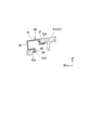
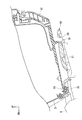
図11に示すように、フロントフック33は、収納ボックス30の側に設けられている。フロントフック33は、ボックス本体31の前下部から下方に延びた後に後方に屈曲して延びるL字状をなしている。
図11に示すように、フロントフック33は、収納ボックス30の側に設けられている。フロントフック33は、ボックス本体31の前下部から下方に延びた後に後方に屈曲して延びるL字状をなしている。
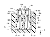
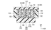
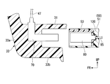
図15に示すように、フロントフック33は、収納ボックス30(図11参照)の前下部から下方に延出する下方延出部33aと、下方延出部33aの下端から後方に延出する後方延出部33b(前後延出部)と、を備える。後方延出部33bは、上方に開口するU字断面(図16参照)を有する箱状をなしている。図16に示すように、フロントフック33における後方延出部33bには、フック側ケース110における前後延在ケース部111を収容可能な空間が設けられている。
図15に示すように、後方延出部33bには、フック側ケース110を介してフック側端子70が一体に設けられている。
図16に示すように、後方延出部33bは、フック側端子70を下方から覆う下壁部33cと、左右フック側端子70を車幅方向外方から覆う縦壁部33dと、を備える。図15に示すように、縦壁部33dは、フック側端子70よりも上方に延出している。縦壁部33dの上端は、収納ボックス30がキャリア50に搭載されたときに、キャリア50の下面に当接する。
図16に示すように、後方延出部33bは、フック側端子70を下方から覆う下壁部33cと、左右フック側端子70を車幅方向外方から覆う縦壁部33dと、を備える。図15に示すように、縦壁部33dは、フック側端子70よりも上方に延出している。縦壁部33dの上端は、収納ボックス30がキャリア50に搭載されたときに、キャリア50の下面に当接する。
<フック側端子>
図15に示すように、フック側端子70は、フロントフック33の内側に設けられている。フック側端子70は、フック側ケース110を介してフロントフック33に取り付けられている。フック側端子70は、左右に一対間隔をあけて配置されている。フック側端子70は、左右フロントフック33のそれぞれに設けられている。フック側端子70は、フロントフック33に沿うように延びるL字状をなしている。フック側端子70は、雄端子である。フック側端子70の一部は、後方延出部33bの延出方向に延出する板状をなしている。フック側端子70は、フロントフック33における後方延出部33bに沿うように前後に延在する前後延在部71と、前後延在部71の前端から上方に延在する上方延在部72と、を備える。
図15に示すように、フック側端子70は、フロントフック33の内側に設けられている。フック側端子70は、フック側ケース110を介してフロントフック33に取り付けられている。フック側端子70は、左右に一対間隔をあけて配置されている。フック側端子70は、左右フロントフック33のそれぞれに設けられている。フック側端子70は、フロントフック33に沿うように延びるL字状をなしている。フック側端子70は、雄端子である。フック側端子70の一部は、後方延出部33bの延出方向に延出する板状をなしている。フック側端子70は、フロントフック33における後方延出部33bに沿うように前後に延在する前後延在部71と、前後延在部71の前端から上方に延在する上方延在部72と、を備える。
図15に示すように、フック側端子70の先端70tは、フロントフック33の先端33tよりも内側に位置している。実施形態において、フック側端子70の先端70tは前後延在部71の後端、フロントフック33の先端33tは縦壁部33dの後端にそれぞれ相当する。すなわち、前後延在部71の後端は、縦壁部33dの後端よりも前方に位置している。
上下延在部72の上端は、フロントフック33の上端よりも上方に位置している。上下延在部72の上端には、コード47の一端が接続されている。なお、コード47の他端は、リッドランプ46(図5参照)に接続されている。
<フック側ケース>
図15に示すように、フロントフック33の内側には、フック側端子70を囲うフック側ケース110が設けられている。フック側ケース110は、フック側端子70に沿うように延びるL字状をなしている。フック側ケース110は、シール部材69を介してフロントフック33に取り付けられている。フック側ケース110は、フック側端子70における前後延在部71に沿うように前後に延在する前後延在ケース部111と、前後延在ケース部111の前端から上方に延在する上方延在ケース部112と、を備える。
図15に示すように、フロントフック33の内側には、フック側端子70を囲うフック側ケース110が設けられている。フック側ケース110は、フック側端子70に沿うように延びるL字状をなしている。フック側ケース110は、シール部材69を介してフロントフック33に取り付けられている。フック側ケース110は、フック側端子70における前後延在部71に沿うように前後に延在する前後延在ケース部111と、前後延在ケース部111の前端から上方に延在する上方延在ケース部112と、を備える。
図15において、フック側ケース110における前後延在ケース部111の前後長さL1を「フック側ケース110の前後長さL1」とする。図15において、フック側端子70における前後延在部71の前後長さL2を「フック側端子70の前後長さL2」とする。実施形態において、フック側端子70の前後長さL2は、フック側ケース110の前後長さL1よりも短い(L2<L1)。
図14に示すように、前後延在ケース部111は、フック側端子70を下方から覆うフック端子下方覆い部113と、左右フック側端子70を車幅方向外方から覆うフック端子側方覆い部114と、左右フック側端子70の収容空間を車幅方向に区画する左右一対のフック端子側縦壁部115と、を備える。
フック端子側方覆い部114およびフック端子側縦壁部115は、フック側端子70の前後延在部71に沿うように前後に延在している。フック端子側方覆い部114およびフック端子側縦壁部115は、フック側端子70の前後延在部71よりも後方に延出している。
フック端子側方覆い部114およびフック端子側縦壁部115は、フック側端子70の前後延在部71よりも上方に延出している。
フック端子側方覆い部114およびフック端子側縦壁部115は、フック側端子70の前後延在部71よりも上方に延出している。
図16に示すように、左右一対のフック端子側方覆い部114は、受け側ケース120を受け入れ可能に車幅方向に離反している。車幅方向において、左右一対のフック端子側方覆い部114の離反間隔は、受け側ケース120の車幅方向の長さ以上の大きさを有する。
左右一対のフック端子側縦壁部115は、受け側ケース120の隔壁124を受け入れ可能に車幅方向に離反している。車幅方向において、左右一対のフック端子側縦壁部115の離反間隔は、受け側ケース120の隔壁124の幅以上の大きさを有する。
<フロントフック受け部>
実施形態において、フロントフック受け部53は、キャリア本体51の前部のうち上下開口部51h(図7参照)に上方から臨む部分である。フロントフック受け部53は、収納ボックス30がキャリア50に搭載されたときに、荷重を受ける部分である。図15に示すように、フロントフック受け部53は、収納ボックス30(ボックス本体31)の底部とフロントフック33の先端部との上下間に入り込むことが可能な厚みを有する。図7に示すように、フロントフック受け部53の下面側には、フロントフック33における後方延出部33b(図15参照)を前方から受け入れ可能に後方に開口する後方開口部53hが設けられている。
実施形態において、フロントフック受け部53は、キャリア本体51の前部のうち上下開口部51h(図7参照)に上方から臨む部分である。フロントフック受け部53は、収納ボックス30がキャリア50に搭載されたときに、荷重を受ける部分である。図15に示すように、フロントフック受け部53は、収納ボックス30(ボックス本体31)の底部とフロントフック33の先端部との上下間に入り込むことが可能な厚みを有する。図7に示すように、フロントフック受け部53の下面側には、フロントフック33における後方延出部33b(図15参照)を前方から受け入れ可能に後方に開口する後方開口部53hが設けられている。
<受け側端子>
図15に示すように、受け側端子80は、フロントフック受け部53に設けられている。図16に示すように、受け側端子80は、キャリア50の下面側に設けられている。図17に示すように、受け側端子80は、雌端子である。受け側端子80は、フック側端子70を挟む一対の端子片81を備える。一対の端子片81は、各収容空間に一組ずつ設けられている。一対の端子片81は、車幅方向に対向している。
図15に示すように、受け側端子80は、フロントフック受け部53に設けられている。図16に示すように、受け側端子80は、キャリア50の下面側に設けられている。図17に示すように、受け側端子80は、雌端子である。受け側端子80は、フック側端子70を挟む一対の端子片81を備える。一対の端子片81は、各収容空間に一組ずつ設けられている。一対の端子片81は、車幅方向に対向している。
一対の端子片81は、前後方向に延在している。一対の端子片81の前端部は、前側ほど車幅方向外方に位置するように傾斜している。これにより、一対の端子片81間にフック側端子70を導入しやすい。
一対の端子片81の前後中間部には、フック側端子70に向けて突出する凸部81aが設けられている。図17の断面視で、凸部81aは、フック側端子70に向けて凸をなす円弧状をなしている。すなわち、フック側端子70と凸部81aとの接触部分が端子70,80の接点部となる。
一対の端子片81の後端部は、互いに接続されている。一対の端子片81の後端は、受け側ケース120の後端(受け端子後方覆い部123)よりも後方に位置している。一対の端子片81の後端は、配線85(図14参照)を介して車体側のバッテリ(不図示)に接続されている。
<受け側ケース>
図16に示すように、フック受け部53には、受け側端子80を囲う受け側ケース120が設けられている。図13に示すように、受け側ケース120は、前方および下方が開口した箱状をなしている。図16に示すように、受け側ケース120は、キャリア50(天壁51a)の下面に取り付けられている。すなわち、受け側ケース120は、フロントフック受け部53の下面に取り付けられている。図14に示すように、受け側ケース120は、受け側端子80を上方から覆う受け端子上方覆い部121と、受け側端子80を車幅方向外方から覆う受け端子側方覆い部122と、受け側端子80を後方から覆う受け端子後方覆い部123と、を備える。
図16に示すように、フック受け部53には、受け側端子80を囲う受け側ケース120が設けられている。図13に示すように、受け側ケース120は、前方および下方が開口した箱状をなしている。図16に示すように、受け側ケース120は、キャリア50(天壁51a)の下面に取り付けられている。すなわち、受け側ケース120は、フロントフック受け部53の下面に取り付けられている。図14に示すように、受け側ケース120は、受け側端子80を上方から覆う受け端子上方覆い部121と、受け側端子80を車幅方向外方から覆う受け端子側方覆い部122と、受け側端子80を後方から覆う受け端子後方覆い部123と、を備える。
図13に示すように、受け側ケース120には、受け端子上方覆い部121から下方に延出する隔壁124と、受け端子上方覆い部121から車幅方向外方に突出する外方突出部125と、が設けられている。
隔壁124は、受け端子側方覆い部122に沿うように前後に延在している。隔壁124は、受け側端子80の収容空間を車幅方向に区画している。
外方突出部125は、ボルト等の締結部材(不図示)によってキャリア50(図11参照)に固定されている。
隔壁124は、受け端子側方覆い部122に沿うように前後に延在している。隔壁124は、受け側端子80の収容空間を車幅方向に区画している。
外方突出部125は、ボルト等の締結部材(不図示)によってキャリア50(図11参照)に固定されている。
図2に示すように、収納ボックス30をキャリア50に取り付けることにより、キャリア50側の受け側端子80(図15参照)と収納ボックス30側のフック側端子70(図15参照)とが接続される。具体的には、図17に示すように、フック受け部53にフック33を接続することにより(図15参照)、一対の端子片81における凸部81aとフック側端子70とが接続される。これにより、車体側のバッテリ(不図示)からリッド32側の電装部品(図5に示すリッドランプ46)に給電可能な状態となる。
<蓋部材>
図8に示すように、収納ボックス給電構造25は、キャリア50に着脱可能に設けられ、収納ボックス30(図2参照)がキャリア50に搭載されていないときに、フロントフック受け部53を覆う蓋部材90を更に備えていてもよい。
図8に示すように、収納ボックス給電構造25は、キャリア50に着脱可能に設けられ、収納ボックス30(図2参照)がキャリア50に搭載されていないときに、フロントフック受け部53を覆う蓋部材90を更に備えていてもよい。
図18に示すように、蓋部材90は、上下開口部51hを上方から覆う上壁91と、後方開口部53hを前方から覆う前壁92と、上壁91に連なりキャリア本体51の天壁51a前端(フロントフック受け部53の下面)に係合する上係合片93と、前壁92に連なりキャリア本体51の爪部51bに係合する前係合片94と、を備える。
<収納ボックスの取付け手順>
以下、収納ボックス30をキャリア50に取り付ける手順の一例を説明する。
例えば、収納ボックス30をキャリア50に取り付ける場合には、以下の(1)~(5)の手順を行う。
(1)まず、持ち手42を持ち上げ、キーシリンダ41を外部に露出させる。
(2)次に、キーシリンダ41にキーを挿入して時計回りに回動し、ボックス本体31のロックを解除する。
(3)次に、収納ボックス30をキャリア50に載置する。
具体的に、図19に示すように、フロントフック33をフロントフック受け部53に押し込んで位置決めする。その後、リアフック34をリアフック受け部54に押し込む(図10参照)。
(4)次に、キーを反時計回りに回動してボックス本体31のロックをかけた後、キーを抜く。
(5)次に、持ち手42をU字溝31uに収納する。
以上の手順により、収納ボックス30をキャリア50に取り付けることができる。
<収納ボックスの取外し手順>
以下、収納ボックス30をキャリア50から取り外す手順の一例を説明する。
例えば、収納ボックス30をキャリア50から取り外す場合には、以下の(1)~(5)の手順を行う。
(1)まず、持ち手42を持ち上げ、ボックス本体解錠ボタン40およびキーシリンダ41を外部に露出させる。
(2)次に、キーシリンダ41にキーを挿入して時計回りに回動し、ボックス本体31のロックを解除する。
(3)次に、ボックス本体解錠ボタン40を押し、収納ボックス30をキャリア50から取り外す。
(4)次に、キーを反時計回りに回動してボックス本体31のロックをかけた後、キーを抜く。
(5)次に、持ち手42をU字溝31uに収納する。
以上の手順により、収納ボックス30をキャリア50から取り外すことができる。
以上説明したように、上記実施形態の収納ボックス給電構造25は、収納ボックス30と、収納ボックス30を車体に着脱自在に搭載可能なキャリア50と、収納ボックス30を前記キャリア50に接続可能とするフック33と、フック33を受けるフック受け部53と、フック33の内側に設けられ、リッドランプ46に給電するためのフック側端子70と、フック受け部53に設けられ、収納ボックス30がキャリア50に搭載されたときに、フック側端子70に接続される受け側端子80と、を備える。
この構成によれば、フック33の内側に設けられ、リッドランプ46に給電するためのフック側端子70と、フック受け部53に設けられ、収納ボックス30がキャリア50に搭載されたときに、フック側端子70に接続される受け側端子80と、を備えることで、以下の効果を奏する。フック33がフック受け部53に引っ掛けられることで、剛性をもって端子70,80を支持することができる。加えて、フック33の内側に給電構造を設けるため、収納ボックス30の底部に新たな給電部を設ける必要がなく、収納ボックス30およびキャリア50の形状を大きく変更する必要もない。したがって、収納ボックス30に新たな給電部を設けることなく、既存の構造を利用した給電構造とし、振動に強く、剛性の高い部位に給電部を設けることができる。
加えて、フック33をフック受け部53に取り付けるときの摩擦によって、端子70,80のセルフクリーニングを行うことができる。例えば、端子70,80の酸化被膜を除去したり、砂噛み等の異物を除去したりすることができる。
加えて、フック側端子70がフック33の内側に設けられることで、フック側端子70が外部に露出しにくくなる。したがって、フック側端子70に塵埃などの異物が付着しにくくなるため、端子70,80の接触信頼性を保持することができる。
また、上記実施形態では、フック33は、フック側端子70が一体に設けられ、前後方向に延出する後方延出部33bを備えることで、以下の効果を奏する。フック33をフック受け部53に取り付けるときに、後方延出部33bにおいて前後方向のスライド動作を作用させることができる。したがって、端子70,80の接続を安定させるとともに、接点部の砂噛みを防止することができる。
また、上記実施形態では、後方延出部33bは、フック側端子70よりも上方に延出し、収納ボックス30がキャリア50に搭載されたときに、キャリア50の下面に当接する縦壁部33dを備えることで、以下の効果を奏する。縦壁部33dの上端とキャリア50の下面とが荷重の受け部となるため、給電部に負荷がかかることを回避することができる。
また、上記実施形態では、フック側端子70は、雄端子であり、フック側端子70の一部は、後方延出部33bの延出方向に延出する板状をなしていることで、フック側端子70によって車幅方向のたわみを吸収することができる。したがって、端子70,80の接続位置のバラツキを吸収するとともに、振動に強い部位に給電部を設けることができる。
加えて、フック33をフック受け部53に取り付けるときに、フック側端子70において前後方向のスライド動作を作用させることができる。したがって、端子70,80の接続を安定させるとともに、接点部の砂噛みを防止することができる。
加えて、フック33をフック受け部53に取り付けるときに、フック側端子70において前後方向のスライド動作を作用させることができる。したがって、端子70,80の接続を安定させるとともに、接点部の砂噛みを防止することができる。
また、上記実施形態では、フック側端子70の先端70tがフック33の先端33tよりも内側に位置することで、フック33とフック受け部53とが位置決めされてからフック側端子70と受け側端子80とが接続される。したがって、収納ボックス30側の端子とキャリア50側の端子とを接続する場合、端子の位置決めを容易に行うことができる。
また、上記実施形態では、フック33の内側には、フック側端子70を覆うフック側ケース110が設けられ、フック側端子70の前後長さL2がフック側ケース110の前後長さL1よりも短いことで、フック側ケース110が位置決めされてからフック側端子70と受け側端子80とが接続される。したがって、収納ボックス30側の端子とキャリア50側の端子とを接続する場合、端子の位置決めを容易に行うことができる。
また、上記実施形態では、受け側端子80がキャリア50の下面側に位置することで、剛性をもって受け側端子80を支持することができる。
また、上記実施形態では、受け側端子80は、雌端子であり、フック側端子70を挟む一対の端子片81を備えることで、以下の効果を奏する。受け側端子80が一つの端子片81のみを備える場合と比較して、フック側端子70と受け側端子80との接続を確実に行うことができる。
また、上記実施形態では、一対の端子片81が車幅方向に対向していることで、一対の端子片81によって上下方向のたわみを吸収することができる。したがって、端子70,80の接続位置のバラツキを吸収するとともに、振動に強い部位に給電部を設けることができる。
また、上記実施形態では、フック受け部53には、受け側端子80を囲い、下方が開口した箱状をなす受け側ケース120が設けられていることで、受け側ケース120によって受け側端子80が外部に露出しにくくなる。
また、上記実施形態では、フック受け部53の下面側には、フック33の後方延出部33bを前方から受け入れ可能に後方に開口する後方開口部53hが設けられていることで、以下の効果を奏する。フック受け部53がフック33を後方から受け入れ可能とされた場合と比較して、フック受け部53に対するフック33のアプローチを容易に行うことができる。例えば、キャリア50が車体後部に設けられたリアキャリア50である場合、収納ボックス30をリアキャリア50に容易に搭載することができる。
また、上記実施形態では、キャリア50には、フック受け部53の近傍で上下に開口する上下開口部51hが設けられていることで、上下開口部51hの開口を通じて水抜きを行うことができる。例えば、雨が降っているときに収納ボックス30をキャリア50に搭載する場合でも、雨水などがフック受け部53に入り込むことを回避することができる。
また、上記実施形態では、キャリア50に着脱可能に設けられ、収納ボックス30がキャリア50に搭載されていないときに、フック受け部53を覆う蓋部材90を更に備えることで、蓋部材90によってフック受け部53が外部に露出することがなくなる。したがって、収納ボックス30がキャリア50に搭載されていないときに、水および塵埃などの異物がフック受け部53に入り込むことを回避することができる。
また、上記実施形態では、フック33が左右に一対設けられていることで、以下の効果を奏する。収納ボックス30とキャリア50とが左右でバランスよく接続されるため、フック33が一つのみ設けられている場合と比較して、振動により強い部位に給電部を設けることができる。
なお、上記実施形態では、収納ボックス30が車両後部に設けられている例を挙げて説明したが、これに限らない。例えば、収納ボックス30は、車両前部に設けられていてもよいし、車両側部(キャリア50の側部)に設けられていてもよい。
また、上記実施形態では、フロントフック33がボックス本体31の前下部から下方に延びた後に後方に屈曲して延びるL字状をなしている例を挙げて説明したが、これに限らない。例えば、フロントフック33は、ボックス本体31の前下部から下方に延びた後に前方に屈曲して延びるL字状をなしていてもよい。
また、上記実施形態では、フック側端子70がフロントフック33の内側に設けられている例を挙げて説明したが、これに限らない。例えば、フック側端子70は、リアフック34の内側に設けられていてもよい。
また、上記実施形態では、フック側端子70が左右フロントフック33のそれぞれに設けられている例を挙げて説明したが、これに限らない。例えば、フック側端子70は、左右フロントフック33の一方にのみ設けられていてもよい。すなわち、フック側端子70は、左右フロントフック33の少なくとも一方に設けられていてもよい。
また、上記実施形態では、フロントフック33が左右に一対設けられている例を挙げて説明したが、これに限らない。例えば、フロントフック33は、1つのみ設けられていてもよいし、3つ以上の複数設けられていてもよい。
また、上記実施形態では、フロントフック受け部53における外方突出部125がボルト等の締結部材(不図示)によってキャリア50に固定されている例を挙げて説明したが、これに限らない。例えば、フロントフック受け部53は、キャリア50に一体的に形成されていてもよい。
また、上記実施形態では、フック側端子70の一部が後方延出部33bの延出方向に延出する板状をなしている例を挙げて説明したが、これに限らない。例えば、フック側端子70の全部が後方延出部33bの延出方向に延出する板状をなしていてもよい。すなわち、フック側端子70の少なくとも一部が後方延出部33bの延出方向に延出する板状をなしていてもよい。
また、上記実施形態では、フック側ケース110がシール部材69を介してフロントフック33に取り付けられている例を挙げて説明したが、これに限らない。例えば、図20に示すように、フック側ケース110は、フロントフック33に直接的に固定されていてもよい。
また、上記実施形態では、左右一対のフック端子側方覆い部114が受け側ケース120を受け入れ可能に車幅方向に離反している例を挙げて説明したが、これに限らない。例えば、図21に示すように、左右一対のフック端子側方覆い部114は、受け側ケース120の車幅方向間に収まる大きさを有していてもよい。すなわち、車幅方向において、左右一対の受け端子側方覆い部122の離反間隔は、フック側ケース110の車幅方向の長さ以上の大きさを有していてもよい。
また、上記実施形態では、受け側ケース120がフロントフック受け部53の下面に取り付けられている例を挙げて説明したが、これに限らない。例えば、図22に示すように、受け側ケース120は、フロントフック受け部53に内蔵されていてもよい。例えば、図23に示すように、受け側ケース120がフロントフック受け部53に内蔵されている構造において、左右一対のフック端子側方覆い部114は、受け側ケース120の車幅方向間に収まる大きさを有していてもよい。
また、上記実施形態では、二つの受け側端子80(二組の一対の端子片81)を囲う受け側ケース120を一つ備えた構成を例に挙げて説明したが、これに限らない。例えば、図24に示すように、一つの受け側端子80(一組の一対の端子片81)を囲う受け側ケース120Aを二つ備えた構成であってもよい。
また、上記実施形態では、フロントフック33が、フック側端子70を下方から覆う下壁部33cと、左右フック側端子70を車幅方向外方から覆う縦壁部33dと、を備える例を挙げて説明したが、これに限らない。例えば、図24に示すように、二つの受け側ケース120Aを備えた構成において、フロントフック33は、受け側端子80の収容空間を車幅方向に区画する第二縦壁部33eを更に備えていてもよい。第二縦壁部33eは、収納ボックス30がキャリア50に搭載されたときに、左右の縦壁部33dとともにキャリア50の下面に当接してもよい。図24において符号110Aは、各受け側ケース120に対応するフック側ケースを示す。
また、上記実施形態では、フック側端子70がフック側ケース110を介してフロントフック33に取り付けられている例を挙げて説明したが、これに限らない。例えば、図25に示すように、フック側端子70は、フロントフック33に直接的に取り付けられていてもよい。すなわち、フロントフック33の内側には、フック側ケース110が設けられていなくてもよい。
また、上記実施形態では、フロントフック33における後方延出部33bには、フック側ケース110における前後延在ケース部111を収容可能な空間が設けられている例を挙げて説明したが、これに限らない。例えば、図26に示すように、フロントフック33における後方延出部33bには、フロントフック受け部53(図25参照)において受け側ケース120を内蔵した部分を収容可能な空間129が設けられていてもよい。
また、上記実施形態では、電装部品としてリッドランプ46を例に挙げて説明したが、これに限らない。例えば、電装部品は、USB充電器およびソレノイドなどの他の電装部品であってもよいし、リッドランプ46以外の他の灯火器類であってもよい。
なお、本発明は上記実施形態に限られるものではなく、例えば、前記鞍乗型車両には、運転者が車体を跨いで乗車する車両全般が含まれ、自動二輪車(原動機付自転車及びスクータ型車両を含む)のみならず、三輪(前一輪且つ後二輪の他に、前二輪且つ後一輪の車両も含む)の車両も含まれる。また、本発明は、自動二輪車のみならず、自動車等の四輪の車両にも適用可能である。
そして、上記実施形態における構成は本発明の一例であり、実施形態の構成要素を周知の構成要素に置き換える等、本発明の要旨を逸脱しない範囲で種々の変更が可能である。
そして、上記実施形態における構成は本発明の一例であり、実施形態の構成要素を周知の構成要素に置き換える等、本発明の要旨を逸脱しない範囲で種々の変更が可能である。
1 自動二輪車(鞍乗型車両)
25 収納ボックス給電構造
30 収納ボックス
33 フロントフック(フック)
33a 下方延出部
33b 後方延出部(前後延出部)
33d 縦壁部
33t フロントフック(フック)の先端
46 リッドランプ(電装部品)
50 キャリア
51h 上下開口部
53 フロントフック受け部(フック受け部)
53h 後方開口部
70 フック側端子
70t フック側端子の先端
71 前後延在部
80 受け側端子
81 端子片
90 蓋部材
110,110A フック側ケース
120,120A 受け側ケース
L1 フック側ケースの前後長さ
L2 フック側端子の前後長さ
25 収納ボックス給電構造
30 収納ボックス
33 フロントフック(フック)
33a 下方延出部
33b 後方延出部(前後延出部)
33d 縦壁部
33t フロントフック(フック)の先端
46 リッドランプ(電装部品)
50 キャリア
51h 上下開口部
53 フロントフック受け部(フック受け部)
53h 後方開口部
70 フック側端子
70t フック側端子の先端
71 前後延在部
80 受け側端子
81 端子片
90 蓋部材
110,110A フック側ケース
120,120A 受け側ケース
L1 フック側ケースの前後長さ
L2 フック側端子の前後長さ
Claims (14)
- 収納ボックス(30)と、
前記収納ボックス(30)を車体に着脱自在に搭載可能なキャリア(50)と、
前記収納ボックス(30)を前記キャリア(50)に接続可能とするフック(33)と、
前記フック(33)を受けるフック受け部(53)と、
前記フック(33)の内側に設けられ、電装部品(46)に給電するためのフック側端子(70)と、
前記フック受け部(53)に設けられ、前記収納ボックス(30)が前記キャリア(50)に搭載されたときに、前記フック側端子(70)に接続される受け側端子(80)と、を備えることを特徴とする鞍乗型車両の収納ボックス給電構造。 - 前記フック(33)は、前記フック側端子(70)が一体に設けられ、前後方向に延出する前後延出部(33b)を備えることを特徴とする請求項1に記載の鞍乗型車両の収納ボックス給電構造。
- 前記前後延出部(33b)は、前記フック側端子(70)よりも上方に延出し、前記収納ボックス(30)が前記キャリア(50)に搭載されたときに、前記キャリア(50)の下面に当接する縦壁部(33d)を備えることを特徴とする請求項2に記載の鞍乗型車両の収納ボックス給電構造。
- 前記フック側端子(70)は、雄端子であり、
前記フック側端子(70)の少なくとも一部は、前記前後延出部(33b)の延出方向に延出する板状をなしていることを特徴とする請求項2または3に記載の鞍乗型車両の収納ボックス給電構造。 - 前記フック側端子(70)の先端(70t)は、前記フック(33)の先端(33t)よりも内側に位置することを特徴とする請求項1から4のいずれか一項に記載の鞍乗型車両の収納ボックス給電構造。
- 前記フック(33)の内側には、前記フック側端子(70)を囲うフック側ケース(110)が設けられ、
前記フック側端子(70)の前後長さ(L2)は、前記フック側ケース(110)の前後長さ(L1)よりも短いことを特徴とする請求項1から5のいずれか一項に記載の鞍乗型車両の収納ボックス給電構造。 - 前記受け側端子(80)は、前記キャリア(50)の下面側に位置することを特徴とする請求項1から6のいずれか一項に記載の鞍乗型車両の収納ボックス給電構造。
- 前記受け側端子(80)は、雌端子であり、前記フック側端子(70)を挟む一対の端子片(81)を備えることを特徴とする請求項1から7のいずれか一項に記載の鞍乗型車両の収納ボックス給電構造。
- 前記一対の端子片(81)は、車幅方向に対向していることを特徴とする請求項8に記載の鞍乗型車両の収納ボックス給電構造。
- 前記フック受け部(53)には、前記受け側端子(80)を囲い、下方が開口した箱状をなす受け側ケース(120)が設けられていることを特徴とする請求項1から9のいずれか一項に記載の鞍乗型車両の収納ボックス給電構造。
- 前記フック(33)は、
前記収納ボックス(30)の下部から下方に延出する下方延出部(33a)と、
前記下方延出部(33a)の下端から後方に延出する後方延出部(33b)と、を備え、
前記フック受け部(53)の下面側には、前記後方延出部(33b)を前方から受け入れ可能に後方に開口する後方開口部(53h)が設けられていることを特徴とする請求項10に記載の鞍乗型車両の収納ボックス給電構造。 - 前記キャリア(50)には、前記フック受け部(53)の近傍で上下に開口する上下開口部(51h)が設けられていることを特徴とする請求項1から11のいずれか一項に記載の鞍乗型車両の収納ボックス給電構造。
- 前記キャリア(50)に着脱可能に設けられ、前記収納ボックス(30)が前記キャリア(50)に搭載されていないときに、前記フック受け部(53)を覆う蓋部材(90)を更に備えることを特徴とする請求項1から12のいずれか一項に記載の鞍乗型車両の収納ボックス給電構造。
- 前記フック(33)は、左右に一対設けられていることを特徴とする請求項1から13のいずれか一項に記載の鞍乗型車両の収納ボックス給電構造。
Priority Applications (3)
| Application Number | Priority Date | Filing Date | Title |
|---|---|---|---|
| US16/763,562 US11554826B2 (en) | 2017-12-28 | 2018-12-27 | Storage box power supply structure for saddled vehicle |
| JP2019562473A JP6961720B2 (ja) | 2017-12-28 | 2018-12-27 | 鞍乗型車両の収納ボックス給電構造 |
| EP18897452.1A EP3699070B1 (en) | 2017-12-28 | 2018-12-27 | Storage box power supply structure for saddled vehicle |
Applications Claiming Priority (2)
| Application Number | Priority Date | Filing Date | Title |
|---|---|---|---|
| JP2017254999 | 2017-12-28 | ||
| JP2017-254999 | 2017-12-28 |
Publications (1)
| Publication Number | Publication Date |
|---|---|
| WO2019131951A1 true WO2019131951A1 (ja) | 2019-07-04 |
Family
ID=67067597
Family Applications (1)
| Application Number | Title | Priority Date | Filing Date |
|---|---|---|---|
| PCT/JP2018/048337 Ceased WO2019131951A1 (ja) | 2017-12-28 | 2018-12-27 | 鞍乗型車両の収納ボックス給電構造 |
Country Status (4)
| Country | Link |
|---|---|
| US (1) | US11554826B2 (ja) |
| EP (1) | EP3699070B1 (ja) |
| JP (1) | JP6961720B2 (ja) |
| WO (1) | WO2019131951A1 (ja) |
Cited By (1)
| Publication number | Priority date | Publication date | Assignee | Title |
|---|---|---|---|---|
| JP2021160606A (ja) * | 2020-03-31 | 2021-10-11 | 本田技研工業株式会社 | 鞍乗り型車両の収納部構造 |
Families Citing this family (2)
| Publication number | Priority date | Publication date | Assignee | Title |
|---|---|---|---|---|
| WO2023285854A1 (en) * | 2021-07-12 | 2023-01-19 | Dingo Co., Ltd. | Multi-purpose grab handle system for a motorcycle |
| US12466325B2 (en) * | 2022-08-01 | 2025-11-11 | Austin Hardware & Supply, Inc. | Bin system |
Citations (6)
| Publication number | Priority date | Publication date | Assignee | Title |
|---|---|---|---|---|
| EP0882644A2 (en) * | 1997-05-30 | 1998-12-09 | Galter S.r.l. | Lighting device for a case-platform combination for vehicles of motorcycle type |
| EP1078848A1 (en) * | 1999-08-27 | 2001-02-28 | Giuseppe Visenzi | Motorbike transport case comprising electric equipment |
| JP2013169862A (ja) * | 2012-02-20 | 2013-09-02 | Honda Motor Co Ltd | 電動車両用電源装置の端子台 |
| JP2013189116A (ja) * | 2012-03-14 | 2013-09-26 | Suzuki Motor Corp | 二輪車用トランク |
| JP2016028920A (ja) * | 2014-07-25 | 2016-03-03 | 本田技研工業株式会社 | 鞍乗り型車両用リアキャリヤ |
| JP2016068766A (ja) | 2014-09-30 | 2016-05-09 | 本田技研工業株式会社 | 鞍乗車両および鞍乗車両用追加収納ボックス |
Family Cites Families (11)
| Publication number | Priority date | Publication date | Assignee | Title |
|---|---|---|---|---|
| DE1911402U (de) * | 1964-12-07 | 1965-03-04 | Fichtel & Sachs Ag | Tasche fuer einspurfahrzeuge, insbesondere mopeds oder kleinrollern. |
| ES2154177B1 (es) * | 1998-09-16 | 2001-10-16 | Nad S A | Maleta para motocicletas. |
| US20060162978A1 (en) * | 2005-01-21 | 2006-07-27 | Harley-Davidson Motor Company | Saddlebag lighting system |
| CN201343090Y (zh) * | 2009-01-14 | 2009-11-11 | 光阳工业股份有限公司 | 电动摩托车的预备电池结合构造 |
| WO2011000398A1 (de) * | 2009-06-30 | 2011-01-06 | Mühlberger GmbH | Anordnung zur verbindung von anbauteilen mit einem fahrzeug |
| WO2012015826A2 (en) * | 2010-07-28 | 2012-02-02 | Stp Industries, Llc | A low profile storage apparatus for a motorcycle |
| JP5701194B2 (ja) * | 2011-10-31 | 2015-04-15 | 本田技研工業株式会社 | 鞍乗型車両用トランク装置の取付構造および該構造を備えた鞍乗型車両並びに鞍乗型車両用トランク装置 |
| KR200460263Y1 (ko) * | 2011-11-29 | 2012-05-16 | 주식회사 제이아이씨 | 오토바이 공구통의 전원 공급장치 |
| GB2504939A (en) * | 2012-08-10 | 2014-02-19 | Ad On The Move Ltd | Mounting display screen to bicycle, motorcycle, etc. |
| US20170341693A1 (en) * | 2016-05-31 | 2017-11-30 | Josef Rzepecki | Pivotable adaptor for a saddle-type seat |
| US20190192363A1 (en) * | 2017-12-21 | 2019-06-27 | Suzanne Mower | Wheelchair Power Supply System |
-
2018
- 2018-12-27 EP EP18897452.1A patent/EP3699070B1/en active Active
- 2018-12-27 US US16/763,562 patent/US11554826B2/en active Active
- 2018-12-27 JP JP2019562473A patent/JP6961720B2/ja not_active Expired - Fee Related
- 2018-12-27 WO PCT/JP2018/048337 patent/WO2019131951A1/ja not_active Ceased
Patent Citations (6)
| Publication number | Priority date | Publication date | Assignee | Title |
|---|---|---|---|---|
| EP0882644A2 (en) * | 1997-05-30 | 1998-12-09 | Galter S.r.l. | Lighting device for a case-platform combination for vehicles of motorcycle type |
| EP1078848A1 (en) * | 1999-08-27 | 2001-02-28 | Giuseppe Visenzi | Motorbike transport case comprising electric equipment |
| JP2013169862A (ja) * | 2012-02-20 | 2013-09-02 | Honda Motor Co Ltd | 電動車両用電源装置の端子台 |
| JP2013189116A (ja) * | 2012-03-14 | 2013-09-26 | Suzuki Motor Corp | 二輪車用トランク |
| JP2016028920A (ja) * | 2014-07-25 | 2016-03-03 | 本田技研工業株式会社 | 鞍乗り型車両用リアキャリヤ |
| JP2016068766A (ja) | 2014-09-30 | 2016-05-09 | 本田技研工業株式会社 | 鞍乗車両および鞍乗車両用追加収納ボックス |
Non-Patent Citations (1)
| Title |
|---|
| See also references of EP3699070A4 |
Cited By (2)
| Publication number | Priority date | Publication date | Assignee | Title |
|---|---|---|---|---|
| JP2021160606A (ja) * | 2020-03-31 | 2021-10-11 | 本田技研工業株式会社 | 鞍乗り型車両の収納部構造 |
| JP7022169B2 (ja) | 2020-03-31 | 2022-02-17 | 本田技研工業株式会社 | 鞍乗り型車両の収納部構造 |
Also Published As
| Publication number | Publication date |
|---|---|
| JPWO2019131951A1 (ja) | 2020-10-22 |
| EP3699070B1 (en) | 2022-03-09 |
| US20200339208A1 (en) | 2020-10-29 |
| EP3699070A4 (en) | 2020-12-02 |
| US11554826B2 (en) | 2023-01-17 |
| JP6961720B2 (ja) | 2021-11-05 |
| EP3699070A1 (en) | 2020-08-26 |
Similar Documents
| Publication | Publication Date | Title |
|---|---|---|
| TWI675780B (zh) | 具有整合佈線之自行車 | |
| CN104903184B (zh) | 跨骑式车辆的电源供给结构 | |
| KR101590738B1 (ko) | 전동 자전거의 전장품 배치 구조 | |
| US9434436B1 (en) | Rear structure for saddle-ride type vehicle | |
| WO2019131951A1 (ja) | 鞍乗型車両の収納ボックス給電構造 | |
| JP6086887B2 (ja) | 鞍乗型車両の車体前部構造 | |
| JP2011068279A (ja) | 鞍乗り型車両のバッテリ周辺構造 | |
| JP6828157B2 (ja) | 自動二輪車 | |
| WO2018179298A1 (ja) | 鞍乗り型車両の車体フレーム構造 | |
| JP2015131553A (ja) | 鞍乗り型車両の施錠構造 | |
| CN104870302A (zh) | 骑乘式车辆 | |
| JP6652630B2 (ja) | 電装品収納構造 | |
| JP5871613B2 (ja) | 鞍乗型車両のシート下収納構造 | |
| JP6916732B2 (ja) | 鞍乗型車両の収納ボックス給電構造 | |
| JP6873277B2 (ja) | 鞍乗型車両の収納ボックス給電構造 | |
| CN105644677A (zh) | 鞍骑型电动车辆 | |
| JP5021191B2 (ja) | 電装品の取外し防止構造 | |
| JP6244285B2 (ja) | 鞍乗り型車両 | |
| CN100443355C (zh) | 带支架锁定装置的自动二轮车 | |
| JP5594159B2 (ja) | 自動二輪車のバッテリー保持構造 | |
| JP2013252807A (ja) | 電装品取付構造 | |
| JP6383622B2 (ja) | 鞍乗型車両のロック器具の収納構造 | |
| CN220616019U (zh) | 鞍乘型车辆 | |
| JP2022180187A (ja) | バッテリ収容装置及び電動車両 | |
| BR102015024630B1 (pt) | Veículo de montar do tipo sela |
Legal Events
| Date | Code | Title | Description |
|---|---|---|---|
| 121 | Ep: the epo has been informed by wipo that ep was designated in this application |
Ref document number: 18897452 Country of ref document: EP Kind code of ref document: A1 |
|
| ENP | Entry into the national phase |
Ref document number: 2019562473 Country of ref document: JP Kind code of ref document: A |
|
| ENP | Entry into the national phase |
Ref document number: 2018897452 Country of ref document: EP Effective date: 20200518 |
|
| NENP | Non-entry into the national phase |
Ref country code: DE |