WO2019132032A1 - 把持力計測装置 - Google Patents
把持力計測装置 Download PDFInfo
- Publication number
- WO2019132032A1 WO2019132032A1 PCT/JP2018/048582 JP2018048582W WO2019132032A1 WO 2019132032 A1 WO2019132032 A1 WO 2019132032A1 JP 2018048582 W JP2018048582 W JP 2018048582W WO 2019132032 A1 WO2019132032 A1 WO 2019132032A1
- Authority
- WO
- WIPO (PCT)
- Prior art keywords
- pressure
- sensor
- sensors
- measuring device
- gripping force
- Prior art date
- Legal status (The legal status is an assumption and is not a legal conclusion. Google has not performed a legal analysis and makes no representation as to the accuracy of the status listed.)
- Ceased
Links
Images


Classifications
-
- G—PHYSICS
- G01—MEASURING; TESTING
- G01L—MEASURING FORCE, STRESS, TORQUE, WORK, MECHANICAL POWER, MECHANICAL EFFICIENCY, OR FLUID PRESSURE
- G01L1/00—Measuring force or stress, in general
- G01L1/20—Measuring force or stress, in general by measuring variations in ohmic resistance of solid materials or of electrically-conductive fluids; by making use of electrokinetic cells, i.e. liquid-containing cells wherein an electrical potential is produced or varied upon the application of stress
- G01L1/22—Measuring force or stress, in general by measuring variations in ohmic resistance of solid materials or of electrically-conductive fluids; by making use of electrokinetic cells, i.e. liquid-containing cells wherein an electrical potential is produced or varied upon the application of stress using resistance strain gauges
-
- A—HUMAN NECESSITIES
- A61—MEDICAL OR VETERINARY SCIENCE; HYGIENE
- A61B—DIAGNOSIS; SURGERY; IDENTIFICATION
- A61B5/00—Measuring for diagnostic purposes; Identification of persons
- A61B5/22—Ergometry; Measuring muscular strength or the force of a muscular blow
- A61B5/224—Measuring muscular strength
- A61B5/225—Measuring muscular strength of the fingers, e.g. by monitoring hand-grip force
-
- A—HUMAN NECESSITIES
- A61—MEDICAL OR VETERINARY SCIENCE; HYGIENE
- A61B—DIAGNOSIS; SURGERY; IDENTIFICATION
- A61B5/00—Measuring for diagnostic purposes; Identification of persons
- A61B5/103—Measuring devices for testing the shape, pattern, colour, size or movement of the body or parts thereof, for diagnostic purposes
- A61B5/11—Measuring movement of the entire body or parts thereof, e.g. head or hand tremor or mobility of a limb
- A61B5/1124—Determining motor skills
- A61B5/1125—Grasping motions of hands
-
- A—HUMAN NECESSITIES
- A61—MEDICAL OR VETERINARY SCIENCE; HYGIENE
- A61B—DIAGNOSIS; SURGERY; IDENTIFICATION
- A61B5/00—Measuring for diagnostic purposes; Identification of persons
- A61B5/68—Arrangements of detecting, measuring or recording means, e.g. sensors, in relation to patient
- A61B5/6801—Arrangements of detecting, measuring or recording means, e.g. sensors, in relation to patient specially adapted to be attached to or worn on the body surface
- A61B5/6813—Specially adapted to be attached to a specific body part
- A61B5/6825—Hand
-
- G—PHYSICS
- G01—MEASURING; TESTING
- G01L—MEASURING FORCE, STRESS, TORQUE, WORK, MECHANICAL POWER, MECHANICAL EFFICIENCY, OR FLUID PRESSURE
- G01L1/00—Measuring force or stress, in general
- G01L1/20—Measuring force or stress, in general by measuring variations in ohmic resistance of solid materials or of electrically-conductive fluids; by making use of electrokinetic cells, i.e. liquid-containing cells wherein an electrical potential is produced or varied upon the application of stress
- G01L1/205—Measuring force or stress, in general by measuring variations in ohmic resistance of solid materials or of electrically-conductive fluids; by making use of electrokinetic cells, i.e. liquid-containing cells wherein an electrical potential is produced or varied upon the application of stress using distributed sensing elements
-
- G—PHYSICS
- G01—MEASURING; TESTING
- G01L—MEASURING FORCE, STRESS, TORQUE, WORK, MECHANICAL POWER, MECHANICAL EFFICIENCY, OR FLUID PRESSURE
- G01L5/00—Apparatus for, or methods of, measuring force, work, mechanical power, or torque, specially adapted for specific purposes
- G01L5/0028—Force sensors associated with force applying means
-
- A—HUMAN NECESSITIES
- A61—MEDICAL OR VETERINARY SCIENCE; HYGIENE
- A61B—DIAGNOSIS; SURGERY; IDENTIFICATION
- A61B2562/00—Details of sensors; Constructional details of sensor housings or probes; Accessories for sensors
- A61B2562/02—Details of sensors specially adapted for in-vivo measurements
- A61B2562/0247—Pressure sensors
Definitions
- the present disclosure relates to an apparatus for measuring hand force.
- Patent Document 1 proposes a device for evaluating the ingenuity of fingers and the operation ability of an object, and a device for measuring multi-directional force applied by hand is proposed. It is done.
- One aspect of the present disclosure is a gripping force measurement device that measures the gripping force of a subject, and includes a main body and a plurality of pressure sensors held by the main body.
- the plurality of pressure sensors are a first sensor that is at least one pressure sensor, and a pressure sensor other than the first sensor, and two or more second sensors whose pressure sensitive surfaces face in the same direction, including.
- the pressure-sensitive surface of the first sensor and the pressure-sensitive surfaces of the two or more second sensors press the pressure-sensitive surfaces of the two or more second sensors while the subject applies the pressure to the pressure-sensitive surfaces of the first sensor.
- the gripping force measuring device is arranged to be grippable by the subject.
- the following problems may occur in the gripping force measuring device provided with only one-to-two pressure-sensitive sensors pressurized by the thumb and the other fingers. For example, depending on the positional relationship between the thumb and the other fingers, a rotational moment may be generated in the gripping force measuring device. As a result, not only the accurate measurement of the gripping force can not be performed, but also the gripping itself of the gripping force measuring device may become difficult.
- the grasping force measurement device according to one aspect of the present disclosure described above since two or more second sensors are provided, it is possible to hold two or more fingers with respect to the thumb, thereby making it possible to Problems are less likely to occur.
- the same direction in two or more second sensors is not limited to the same direction in a strict sense, and even in the range where the same effect as described above is exerted, there is a small difference in the direction It is said that the directions are substantially the same.
- the main body portion may be configured to be capable of changing the holding position of at least one of the first sensor and the two or more second sensors.
- the force measurement can be appropriately performed by changing the position of the pressure-sensitive surface of the pressure-sensitive sensor according to the hand of the subject.
- the guiding portion is further provided on the main body portion, and by contacting with the finger of the subject, a pressure-sensitive surface of at least one of the two or more second sensors.
- a guide unit may be provided to guide the position of the finger with respect to.
- the finger of the subject can be brought into contact with an appropriate position, so that measurement of force can be appropriately performed.
- the main body portion may include a plurality of buttons for pressing a plurality of pressure sensors. Further, among the plurality of buttons, a button for pressing the pressure sensitive surface of the first sensor and a button for pressing at least one pressure sensitive surface of the pressure sensitive surfaces of the two or more second sensors are And may be disposed at a position projecting outward from the main body.
- the main body portion may be configured to be capable of changing the distance between the first sensor and the two or more second sensors.
- the position of the button for pressing the pressure-sensitive surface of the pressure sensor can be changed in accordance with the hand of the subject, and force measurement can be appropriately performed.
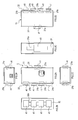
- FIG. 1A is a perspective view showing a gripping force measuring device according to the first embodiment
- FIG. 1B is a perspective view of a viewpoint different from FIG. 1A showing the gripping force measuring device.
- 2A is a right side view showing the gripping force measuring device of the first embodiment
- FIG. 2B is a front view showing the gripping force measuring device
- FIG. 2C is a rear view showing the gripping force measuring device
- 2D is a left side view showing the gripping force measuring device
- FIG. 2E is a bottom view showing the gripping force measuring device
- FIG. 2F is a plan view showing the gripping force measuring device.
- FIG. 3A is a cross-sectional view showing a pressure sensor and a button
- FIG. 3B is a perspective view showing the button.
- FIG. 3C is a perspective view illustrating the arrangement of the pressure sensor and the button. It is.
- FIG. 4A is a plan view showing a state in which the button is moved
- FIG. 4B is a perspective view showing that state
- FIG. 4C is a plan view showing the state in which the button is moved to another position. It is a perspective view of the state.
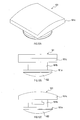
- FIG. 5A is a view for explaining the shape of the contact portion of the button
- FIG. 5B is a view showing the gripping force measuring device gripped by the subject's hand. It is a block diagram showing a grasping force measuring device of a 1st embodiment.
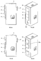
- FIG. 8A is a perspective view showing a gripping force measuring device according to a second embodiment
- FIG. 8B is a perspective view from a different point of view from FIG. 8A showing the gripping force measuring device.
- FIG. 9A is a rear view showing the gripping force measuring device according to the second embodiment
- FIG. 9B is a cross-sectional view taken along the line IXB-IXB of FIG. 9A
- FIG. 9C shows a state in which the main body of the gripping force measuring device is deformed.
- FIG. 9D is a rear view showing the same
- FIG. 9D is a cross-sectional view taken along the line IXD-IXD of FIG. 9C. It is a perspective view showing a grasping force measuring device of a modification.
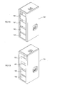
- FIG. 11A is a perspective view showing a gripping force measuring device according to a modification
- FIG. 11B is a perspective view showing the gripping force measuring device according to the modification.
- 12A is a perspective view showing a modified button
- FIG. 12B is a side view showing a modified button
- FIG. 12C is a plan view showing the modified button. It is sectional drawing which shows the pressure sensor of a modification, a button, and its periphery.
- the gripping force measuring device 1 for measuring the gripping force of a subject comprises a main body 11 and a plurality of pressure sensitive sensors held by the main body 11. And a sensor.
- the plurality of pressure sensors include a first sensor 21a which is one pressure sensor, and four second sensors 21b which are pressure sensors other than the first sensor.
- first sensor 21a corresponds to the first finger
- the four second sensors 21b correspond to the second to fifth fingers.
- the main body portion 11 is a casing having a substantially rectangular parallelepiped shape.
- the main body 11 holds a plurality of buttons 41, a power button 42, an LED 43, a connection interface 44, and the like, which will be described later, in addition to the plurality of pressure sensors 21 described above. Further, the main body unit 11 internally holds a control / communication module 61, a battery 68, and the like described later.
- the first sensor 21 a includes a variable resistance portion 23 and a plurality of electrodes 24 disposed below the variable resistance portion 23.
- the variable resistance portion 23 may have a disk shape when viewed from the direction in which the button 41 is pressed (pressure direction). At least one of the plurality of electrodes 24 is used as a signal electrode, and at least one is used as a ground electrode.
- the variable resistance portion 23 is a material to which conductivity is imparted by dispersing a conductive filler in an elastomer material, and is configured of a conductive foam elastomer material which is a material obtained by foaming the elastomer material. When the variable resistance portion 23 is pressurized, it is compressed according to the pressure, and the electric resistance decreases as the amount of compression increases.
- variable resistance portion 23 is formed so as to have a thickness in the range of 1 mm to 10 mm in the non-pressurized state, and configured to have an electrical resistance of 1 ⁇ 10 3 ⁇ or more. There is. Further, in the pressurized state, the variable resistance portion 23 is compressed to 80% or less of the thickness in the non-pressurized state, and the electric resistance becomes 1/500 to 1/10 of the electric resistance in the non-pressured state. Is configured as.
- a cable 51 is connected to the plurality of electrodes 24.
- An electrical signal corresponding to the electrical resistance is output to the control / communication module 61 by the cable 51 and is output to an external device (PC 71 described later).
- the button 41 corresponding to the first sensor 21a is attached to one surface of the first sensor 21a.
- the button 41 for the first sensor 21a is a button for pressing the pressure sensitive surface of the first sensor 21a.
- the pressure-sensitive surface referred to here is a surface on which the first sensor 21a can detect the pressing force when the surface is pressed, and in the first embodiment, the button in the disk-shaped variable resistance portion 23 It indicates the side on which 41 is provided.
- the direction in which the pressure sensitive surface faces is the normal direction of the pressure sensitive surface.
- the button for pressing the pressure-sensitive surface is a button that plays an auxiliary role for the subject to apply the finger force to the pressure-sensitive surface.
- the contact surface which is the surface to which the finger applies force, can be positioned away from the pressure-sensitive surface, thereby suppressing erroneous operation of the gripping force measuring device 1 by the subject and improving operability.
- the button 41 is configured by assembling two upper and lower members.
- the button 41 has a disk-like portion 41 a, a columnar portion 41 b, and an abutting portion 41 c.
- the disk-shaped portion 41a has a circular shape whose diameter is larger than the diameter of the first sensor 21a.
- the columnar portion 41 b is a prismatic member extending from the disc-shaped portion 41 a to the opposite side to the first sensor 21 a.
- the contact portion 41 c is a substantially plate-like member provided at the end of the extension of the columnar portion 41 b.
- the contact portion 41c is generally plate-shaped, but the surface on the side of the columnar portion 41b is a flat shape, and the surface on the opposite side protrudes.
- the opposite surface is a rounded shape, more specifically, a shape like a cylinder divided by a surface along the axial direction.
- the first sensor 21 a is disposed in the vicinity of the first surface 31 of the main body 11.
- the four second sensors 21 b are disposed in the vicinity of a second surface 32 provided on the opposite side of the first surface 31 in the main body 11.
- the main body portion 11 holds the first sensor 21a and the second sensor 21b such that the pressure sensitive surface of the first sensor 21a faces in the opposite direction to the pressure sensitive surfaces of the four second sensors 21b.
- the pressure sensitive surfaces of the four second sensors 21b face in the same direction, and the direction is different from the direction in which the pressure sensitive surface of the first sensor 21a faces
- the direction in which the pressure sensitive surface of the first sensor 21a and the pressure sensitive surfaces of the four second sensors 21b are oriented is such that the subject applies pressure on the pressure sensitive surface of the first sensor 21a and presses on the pressure sensitive surfaces of the four second sensors 21b.
- the subject is able to grip the gripping force measuring device 1.
- “Gripable” as used herein means that the gripping force measuring device 1 is lifted and maintained at a constant position by pressing the first sensor 21a and the second sensor 21b with a finger or the like so as to sandwich them as described above. It means that you can.
- the pressure sensitive surfaces of the four second sensors 21b face in the same direction, but these pressure sensitive surfaces may not be completely in the same direction. Specifically, when pressing the first sensor 21a with a thumb, if the other four fingers can press the second sensor 21b in order to grip the gripping force measuring device 1, the pressure-sensitive surface The direction of can be adjusted as appropriate.
- the pressure sensing surface of the pressure sensor 21 has a flat shape, but may have a curved shape.
- the direction of the microscopic pressure sensitive surface may satisfy the above (i) and (ii) at least in any region of each pressure sensitive surface.
- the first surface 31 is provided with a slit 31 a.
- the button 41 is shown by FIG. 3A and 3C, the columnar part 41b is arrange
- the disk-shaped part 41a and the contact part 41c are larger than the slit 31a. Therefore, the button 41 is movable in the first axial direction, which is the lengthwise direction of the slit 31a, within the range of the slit 31a.
- the second surface 32 is provided with a slit 32 a.
- the slit 32a has a length in the same direction as the slit 31a.
- the button 41 is movable in the first axial direction within the range of the slit 32a.
- the first sensor 21a and the second sensor 21b are fixed to the button 41 corresponding to each. Further, the installation surface 52 on which the first sensor 21a is installed is configured such that the first sensor 21a and the second sensor 21b can slide. Therefore, the first sensor 21 a and the second sensor 21 b can be changed in position held by the main body 11 by moving along with the movement of the button 31 in the slits 31 a and 32 a.
- the second sensor 21b can freely move as shown in FIGS. 4A-4D.
- the first sensor 21a can also be freely moved within the range of the slit 31a.
- the gripping force measurement device 1 includes a control / communication module 61 and a battery 68.
- the control / communication module 61 includes an acquisition unit 62, a communication unit 63, a power supply unit 64, and a control unit 65.
- the acquisition unit 62 is an A / D conversion circuit that converts an analog signal that is an output signal of the pressure sensor 21 into a digital signal.
- the output signal of the pressure sensor 21 is a signal that changes corresponding to the above-described electric resistance value.
- the communication unit 63 performs wireless communication with the reception module 72 connected to a computer system (hereinafter, PC 71) external to the gripping force measurement device 1.
- the PC 71 acquires a signal corresponding to the electrical resistance value from the reception module 72, performs necessary processing, and causes the display 73 to display the processing result.
- the power supply unit 64 is connected to a battery 68 that supplies power, and supplies power to each unit of the control and communication module 61.
- the control unit 65 includes a microcomputer having a CPU 66 and a semiconductor memory (hereinafter, a memory 67) such as a RAM, a ROM, and a flash memory.
- a memory 67 such as a RAM, a ROM, and a flash memory.
- the various functions of the control unit 65 are realized by the CPU 66 executing a program stored in a non-transitional tangible recording medium.
- the memory 67 corresponds to a non-transitional tangible storage medium storing a program.
- the pressure sensor 21 detects the pressure applied to the pressure sensitive surface.
- the pressure sensor 21 outputs an electrical signal corresponding to the pressure.
- the acquisition unit 62 acquires an analog signal from the pressure sensor 21, converts it into a digital signal, and transmits the digital signal to the control unit 65.
- control unit 65 stores the digital data from the acquisition unit 62 in the data recording buffer formed in the memory 67 as data of the signal acquired from the pressure sensor 21.
- control unit 65 requests the PC 71 to transmit data via the communication unit 63.
- control unit 65 determines whether the preparation on the receiving side has been completed. If the receiver's preparation is not complete or there is no answer, the process returns to S4. If the preparation on the receiving side has been completed, the process proceeds to S6.
- control unit 65 divides the data stored at S3 into eight bits.
- control unit 65 sequentially transmits the data divided at S6 to the PC 71 via the communication unit 63. After S7, the main measurement process is ended.
- the PC 71 transmits a message to that effect to the gripping force measuring device 1 if the data transmission request is received. Thereafter, the PC 71 receives the data transmitted in S7, and recombines the divided data. Then, the PC 71 calculates a pressure value based on the recombined data, and displays the calculation result on the display.
- the gripping force measuring device 1 applies a force such that the thumb is brought into contact with the first sensor 21a and the fingers other than the thumb are distributed, brought into contact with the four second sensors 21b and pinched
- the finger force information can be obtained in more detail than if the overall grip strength of the is measured.
- the positions of the pressure sensor 21 and the button 41 can be changed, so the position of the pressure sensitive surface of the pressure sensor 21 is changed according to the hand (or the position of the finger) of the subject can do. Therefore, the subject can press the button 41 appropriately, and the force can be measured properly.
- the button 41 is disposed at a position where the button 41 pops out from the main body 11. Therefore, as shown in FIG. 5B, when operating the button 41, the finger contacts the main body 11. It becomes difficult. As a result, it is possible to reduce the risk that the finger force is applied to the main body 11 or to press the pressure sensitive surface of the pressure sensor 21 in an inappropriate direction, and the force can be measured properly. . In addition, since the surface of the contact portion 41c has a shape that follows the arc of an ellipse, the subject can grasp the button 41 in the sense of grasping the oval cylinder.
- the grasping force measurement device 101 includes a first case 111 holding the first sensor 21a and a second case 112 holding the second sensor 21b in the main body 110, and further, It has a change mechanism 121 for changing the distance between the first housing 111 and the second housing 112.
- the change mechanism 121 has an internal thread portion 122 provided in the first housing 111 and an external thread portion 123 provided in the second housing 112.
- the female screw portion 122 is a cylindrical member in which a female screw is formed inside, and is fixed to the first housing 111.
- the female screw portion 122 is arranged to have an opening at an end in a direction from the first housing 111 to the second housing 112. In the second embodiment, the direction from the first casing 111 to the second casing 112 is the rear.
- the male screw portion 123 is provided in the second housing 112 such that a tip portion on which a screw thread is formed is directed to the front opposite to the rear. Further, the male screw portion 123 is rotatable around an axis in the front-rear direction which is the length direction. Although the specific shape is not illustrated, the male screw portion 123 is configured to be immovable relative to the second housing 112 in the front-rear direction.
- the second housing 112 can enter the inside of the first housing 111.
- the male screw portion 123 can be inserted into the female screw portion 122.
- the female screw portion 122 and the male screw portion 123 are screwed together, whereby the positional relationship between the first housing 111 and the second housing 112 in the front-rear direction is determined.
- the insertion depth of the male screw portion 123 into the female screw portion 122 is changed, whereby the distance in the front-rear direction between the first housing 111 and the second housing 112 is changed.
- the first housing 21 is provided with the first sensor 21a
- the second housing 112 is provided with the second sensor 21b. Therefore, the main body 110 can change the distance between the button 41 for pressing the pressure sensitive surface of the first sensor 21a and the button 41 for pressing the pressure sensitive surface of the second sensor 21b. This distance can be configured to be adjustable within the range of at least 40 to 100 mm.
- the configuration in which one first sensor 21a is provided in the first housing 111 and two second sensors 21b are provided in the second housing 112 is exemplified.
- Two second sensors 21 b may be provided in the case 111, and one first sensor 21 a may be provided in the second case 112.
- the distance between the button 41 for pressing the pressure-sensitive surface of the first sensor 21a and the button 41 for pressing the pressure-sensitive surface of the second sensor 21b is adjusted to the subject's hand. It can be changed. Therefore, measurement of force can be appropriately performed by the gripping force measurement device 101.
- the configuration is exemplified in which one first sensor 21 a is disposed on the first surface 31 of the main body 11 and four second sensors 21 b are disposed on the second surface 32.
- the number of pressure sensors 21 disposed is not limited to this. At least one pressure sensor 21 may be disposed on the first surface 31, that is, two or more pressure sensors 21 may be provided. Further, at least two pressure sensors 21 may be disposed on the second surface 32, and three or more pressure sensors 21 may be provided.
- the 1st 1st sensor 21a was provided in the 1st housing
- two or more first sensors 21 a may be provided in the first housing 111, and three or more second sensors 21 b may be provided in the second housing 112.
- the pressure-sensitive surface of the first sensor 21a and the pressure-sensitive surface of the second sensor 21b are arranged to face in opposite directions.
- the directions of the pressure sensitive surfaces thereof are not necessarily opposite to each other, and are disposed to face the inclined direction. It may be
- the pressure sensing surfaces of the plurality of second sensors 21b may not all face in the same direction, and the pressure sensing surfaces of one or more second sensors 21b are configured to face in a direction different from that of the other second sensors 21b. It may be
- the button 41 may be disposed to protrude along the direction in which the pressure-sensitive surface faces, or protrudes in a direction inclined from the direction in which the pressure-sensitive surface faces. May be
- buttons 41 and the pressure sensors 21 can be changed by sliding.
- the buttons 41 and the pressure sensor may be configured to be able to change the position, or any of the buttons 41 may not be able to change the position.
- the first sensor 21a that can be used with the thumb and the corresponding button 41 may be configured to be slidable, or only one or more second sensors 21b may be configured to be slidable. It is also good.
- the main body portion is provided with a guiding portion for guiding the position of the subject's finger with respect to the pressure sensing surface of at least one of the two or more second sensors 21b by contacting with the subject's finger May be
- a plate-like guide portion 131 can be provided along the four buttons 41 corresponding to the second sensor 21b. Since the position of the finger is roughly determined by the contact of the fingertip with the guide portion 131, the fingertip can be guided to the appropriate position of the button 41.
- the shape of the guide portion is not limited to the shape shown in FIG. 10, and can be various shapes that can guide the position of the finger. Moreover, it is not necessary to provide the guide part 131 with respect to all the fingers, and a guide part may be provided only with respect to the one part finger.
- the tip of the button 41 may have a planar shape, or may have a concave shape in which the central portion is recessed.
- the tip end surface of the planar button 142 may be configured to be flush with the outer surface of the main body portion 141. Further, as shown in FIG. 11B, the tip end surface of the button 152 may be disposed inside the outer surface of the main body 151.
- the shape of the main body is not particularly limited as long as a plurality of pressure sensors can be held.
- it may have a cylindrical shape.
- the shape of the main body portion may be a shape in which a rod-like body, a cylindrical body, a block body, and the like are appropriately combined.
- the configuration using the conductive foam elastomer material as the pressure sensor and using the sensor that measures the pressure based on the electric resistance that changes due to the pressure application is illustrated.
- the pressure-sensitive sensor that can be used for the gripping force measurement device of the present disclosure may be a sensor other than the above-described sensor.
- a sensor using a comb electrode may be adopted as a pressure sensor.
- a sensor using a comb electrode is a sensor that detects pressure from a change in electrical resistance due to a change in contact area with the film when pressurized.
- the sensor may be configured to detect a pressure by a change in capacitance when pressurized.
- a load cell having a Wheatstone bridge circuit may be used as the pressure sensor.
- the button 161 includes a disk-like portion 161 a, a columnar portion 161 b, an abutment portion 161 c, and an abutment assisting portion 162.
- the disk-like portion 161a, the columnar portion 161b, and the contact portion 161c have the same shape as the disk-like portion 41a, the columnar portion 41b, and the contact portion 41c of the button 41 described above.
- the contact assisting portion 162 is a spherical rubber and is provided below the disk-like portion 161a.
- the sensor periphery can be configured as shown in FIG.
- the button 161 is disposed such that the contact assisting portion 162 is positioned along the pressure sensing surface of the thin pressure sensor 171 using a comb-shaped electrode.
- the tip of the contact assisting portion 162 pressurizes the pressure sensor 171, and the pressure is measured from the change of the electric resistance of the comb electrode.
- the pressure force is concentrated on the tip of the contact assisting portion 162, so that the pressure sensor 171 can preferably measure the pressure.
- the contact surface between the pressure sensor 171 and the contact assisting portion 162 is small, and the pressure sensor 171 and the button 161 can not be fixed. Therefore, the housing 172 is provided so that the button 161 is at an appropriate position.
- the shape of the contact assisting portion 162 is not particularly limited. For example, it may be cylindrical.
Landscapes
- Health & Medical Sciences (AREA)
- Life Sciences & Earth Sciences (AREA)
- Physics & Mathematics (AREA)
- Medical Informatics (AREA)
- Surgery (AREA)
- Biophysics (AREA)
- Pathology (AREA)
- Engineering & Computer Science (AREA)
- Biomedical Technology (AREA)
- Heart & Thoracic Surgery (AREA)
- Veterinary Medicine (AREA)
- Molecular Biology (AREA)
- Public Health (AREA)
- Animal Behavior & Ethology (AREA)
- General Health & Medical Sciences (AREA)
- General Physics & Mathematics (AREA)
- Physical Education & Sports Medicine (AREA)
- Chemical & Material Sciences (AREA)
- Analytical Chemistry (AREA)
- Physiology (AREA)
- Dentistry (AREA)
- Oral & Maxillofacial Surgery (AREA)
- Force Measurement Appropriate To Specific Purposes (AREA)
Abstract
把持力計測装置は、本体部と、複数の感圧センサと、を備える。複数の感圧センサは、少なくとも1つの第1センサと、感圧面が同方向を向く2つ以上の第2センサと、を含む。上記第1センサの感圧面及び上記2つ以上の第2センサの感圧面は、被験者が上記第1センサの感圧面を加圧するとともに、上記2つ以上の第2センサの感圧面を加圧したときに、当該把持力計測装置が被験者によって把持可能となるように配置されている。
Description
本国際出願は、2017年12月28日に日本国特許庁に出願された日本国特許出願2017-254807号に基づく優先権を主張するものであり、日本国特許出願2017-254807号の全内容を参照により本国際出願に援用する。
本開示は、手の力を測定する装置に関する。
従来、指の力などの手の情報を取得する様々な装置が提案されている。握力計もその一例である。また握力計以外にも、特許文献1には、手指の巧緻性や物体の操作能力を評価することを目的とする装置であって、手によって加えられた多方向の力を測定する装置が提案されている。
従来の装置では、例えば、いずれの指の力が他の指と比較して弱いか、といった手の力の詳細な情報を取得することが難しかった。
本開示の一局面は、指の力に関する詳細な情報を取得することができる技術を提案することが望ましい。
本開示の一態様は、被験者の把持力を計測する把持力計測装置であって、本体部と、上記本体部に保持される複数の感圧センサと、を備える。上記複数の感圧センサは、少なくとも1つの感圧センサである第1センサと、上記第1センサ以外の感圧センサであって、感圧面が同方向を向く2つ以上の第2センサと、を含む。上記第1センサの感圧面及び上記2つ以上の第2センサの感圧面は、被験者が上記第1センサの感圧面を加圧するとともに、上記2つ以上の第2センサの感圧面を加圧したときに、当該把持力計測装置が被験者によって把持可能となるように配置されている。
このような構成であれば、複数の感圧センサごとに圧力を取得できるため、手の全体の握力を測定する場合よりも詳細な指の力の情報を取得することができる。例えば、第1センサに親指を当接させ、複数の第2センサに親指以外の指を分散して当接させて挟むように力を加えることで、指の力の情報が取得できる。
また、上記把持力計測装置とは異なり、拇指とその他の指により加圧される1対2個の感圧センサのみを備える把持力計測装置では、つぎのような問題が生じるおそれがある。例えば、拇指とその他の指の位置関係によっては、把持力計測装置に回転モーメントを生じてしまう。その結果、正確な把持力の計測ができないばかりでなく、把持力計測装置の把持そのものが困難になるおそれがある。しかしながら上述した本開示の一態様の把持力計測装置では、2つ以上の第2センサが設けられているため、拇指に対する指を2本以上として把持をすることが可能であり、それにより、上述した問題が生じにくくなる。
ここで、2つ以上の第2センサにおける「同方向」とは、厳密な意味での同方向に限るものではなく、上記と同様の効果を奏する範囲においては、方向に小さな差異があっても実質的に同方向であるといる。
上述した把持力計測装置において、上記本体部は、上記第1センサ及び上記2つ以上の第2センサのうち少なくとも1つのセンサについて、当該センサの保持位置を変更可能に構成されていてもよい。
このような構成であれば、感圧センサの感圧面の位置を被験者の手に合わせて変更することで、力の計測を適切に行うことができる。
また上述した把持力計測装置において、さらに、上記本体部に設けられる案内部であって、被験者の指と当接することにより、上記2つ以上の第2センサのうちの少なくとも1つのセンサの感圧面に対する上記指の位置を案内する案内部を備えていてもよい。
このような構成であれば、被験者の指を適正な位置に当接させることができるため、力の計測を適切に行うことができる。
また上述した把持力計測装置において、上記本体部は、複数の感圧センサを加圧するための複数のボタンを備えていてもよい。また、複数のボタンのうち、上記第1センサの感圧面を加圧するためのボタン、及び、上記2つ以上の第2センサの感圧面のうちの少なくとも1つの感圧面を加圧するためのボタンは、上記本体部から外部に張り出した位置に配置されていてもよい。
このような構成であれば、感圧面に指の力を加えるときに指が本体部に接触しにくくなる。これにより、指の力が本体部に加わってしまったり、感圧センサの感圧面を不適当な方向に加圧してしまったりする危険を低減でき、力の計測を適切に行うことができる。
また上述した把持力計測装置において、上記本体部は、上記第1センサと、上記2つ以上の第2センサとの距離が変更可能に構成されていてもよい。
このような構成であれば、感圧センサの感圧面を加圧するボタンの位置を被験者の手に合わせて変更することができ、力の計測を適切に行うことができる。
1…把持力計測装置、11…本体部、21…感圧センサ、21a…第1センサ、21b…第2センサ、23…可変抵抗部、24…電極、31…第1面、31a…スリット、32…第2面、32a…スリット、41…ボタン、41a…円板状部、41b…柱状部、41c…当接部、42…電源ボタン、43…LED、44…接続インターフェース、51…ケーブル、52…設置面、61…制御・通信モジュール、62…取得部、63…通信部、64…電源部、65…制御部、66…CPU、67…メモリ、68…バッテリー、71…PC、72…受信モジュール、73…ディスプレイ、101…把持力計測装置、110…本体部、111…第1筐体、112…第2筐体、121…変更機構、122…雌ねじ部、123…雄ねじ部、131…案内部、141…本体部、142…ボタン、151…本体部、152…ボタン、161…ボタン、162…当接補助部、171…感圧センサ、172…筐体
以下に本開示の実施形態を図面と共に説明する。
[1.第1実施形態]
[1-1.全体構成]
図1A-1B及び図2A-2Fに示されるように、被験者の把持力を計測する第1実施形態の把持力計測装置1は、本体部11と、本体部11に保持される複数の感圧センサと、を備える。複数の感圧センサは、1つの感圧センサである第1センサ21aと、第1センサ以外の感圧センサである4つの第2センサ21bと、を含む。なお、第1センサ21a及び第2センサ21bを区別しない場合には、それらを感圧センサ21とも記載する。なお、第1実施形態においては、第1センサ21aは第1指に対応し、4つの第2センサ21bが第2~5指に対応する。
[1-1.全体構成]
図1A-1B及び図2A-2Fに示されるように、被験者の把持力を計測する第1実施形態の把持力計測装置1は、本体部11と、本体部11に保持される複数の感圧センサと、を備える。複数の感圧センサは、1つの感圧センサである第1センサ21aと、第1センサ以外の感圧センサである4つの第2センサ21bと、を含む。なお、第1センサ21a及び第2センサ21bを区別しない場合には、それらを感圧センサ21とも記載する。なお、第1実施形態においては、第1センサ21aは第1指に対応し、4つの第2センサ21bが第2~5指に対応する。
本体部11は、略直方体形状である筐体である。本体部11は、上述した複数の感圧センサ21の他、後述する複数のボタン41、電源ボタン42、LED43、接続インターフェース44などを外表面に沿った位置に保持する。また本体部11は、後述する制御・通信モジュール61、バッテリー68などを内部に保持する。
[1-2.感圧センサ及びボタンの構成]
第1センサ21aと4つの第2センサ21bはいずれも同一の構成であるため、第1センサ21aの構成を説明して他のセンサの説明を割愛する。
第1センサ21aと4つの第2センサ21bはいずれも同一の構成であるため、第1センサ21aの構成を説明して他のセンサの説明を割愛する。
図3A、図3Cに示されるように、第1センサ21aは、可変抵抗部23と、可変抵抗部23の下側に配置される複数の電極24とを備える。可変抵抗部23はボタン41が押される方向(加圧方向)から見た場合に円板形状をしていてもよい。複数の電極24は、少なくとも一つが信号電極として利用され、少なくとも一つがグランド電極として利用される。可変抵抗部23は、エラストマー材料中に導電性フィラーを分散させることによって導電性が付与された材料であり、かつエラストマー材料を発泡させた材料である導電性発泡エラストマー材料によって構成されている。可変抵抗部23は、加圧された際には圧力に応じて圧縮されて、その圧縮量が増大するほど電気抵抗が低下する。
本実施形態の場合、可変抵抗部23は、非加圧状態においては、厚みが1mm~10mmの範囲内となるように成形され、電気抵抗が1×10³Ω以上となるように構成されている。また、可変抵抗部23は、加圧状態においては、厚みが非加圧状態における厚みの80%以下に圧縮され、電気抵抗が非加圧状態における電気抵抗の1/500~1/10となるように構成されている。
複数の電極24にはケーブル51が接続されている。このケーブル51によって電気抵抗に応じた電気信号が制御・通信モジュール61に出力され、外部機器(後述するPC71)に出力される。
第1センサ21aの一方の面には、第1センサ21aに対応する1つのボタン41が取り付けられている。第1センサ21a用のボタン41は、第1センサ21aの感圧面を加圧するためのボタンである。ここでいう感圧面とは、その面が加圧されたときに第1センサ21aがその加圧力を検出することができる面であり、第1実施形態では円板形状の可変抵抗部23におけるボタン41が設けられる側の面を指す。以下の説明において、感圧面の向く方向とは、感圧面の法線方向である。
また、感圧面を加圧するためのボタンは、被験者が感圧面に指の力を加えるための補助的な役割を果たすボタンである。このようなボタンによって、指が力を加える面である当接面を感圧面から離れた位置とすることができ、それにより被験者による把持力計測装置1の誤操作の抑制や操作性向上を図る。
図3A-3Bに示されるように、ボタン41は、上下の2つの部材を組み付けて構成される。ボタン41は、円板状部41aと、柱状部41bと、当接部41cと、を有する。円板状部41aは、第1センサ21aの直径よりも直径の大きい円形形状である。柱状部41bは、円板状部41aから第1センサ21aとは逆側に延び出す角柱状の部材である。当接部41cは、柱状部41bの延び出した先に設けられる略板状の部材である。
当接部41cは、全体としては板状であるが、柱状部41b側の面が平面形状で、その反対側の面が突出した形状である。またこの反対側の面は、丸みを帯びた形状であり、より具体的には、軸方向に沿った面で分割した円柱のような形状である。
[1-3.感圧センサの配置]
図2A,図2Dなどに示されるように、第1センサ21aは、本体部11の第1面31の近傍に配置されている。また4つの第2センサ21bは、本体部11における第1面31とは反対側に設けられる第2面32の近傍に配置されている。
図2A,図2Dなどに示されるように、第1センサ21aは、本体部11の第1面31の近傍に配置されている。また4つの第2センサ21bは、本体部11における第1面31とは反対側に設けられる第2面32の近傍に配置されている。
すなわち本体部11は、第1センサ21aの感圧面が、4つの第2センサ21bの感圧面に対して相反する方向を向くように、第1センサ21a及び第2センサ21bを保持している。別の言い方をすると、(i)4つの第2センサ21bの感圧面は同方向を向いており、かつ、その方向は第1センサ21aの感圧面の向く方向とは異なる方向であり、(ii)第1センサ21aの感圧面及び4つの第2センサ21bの感圧面が向く方向は、被験者が第1センサ21aの感圧面を加圧するとともに、4つの第2センサ21bの感圧面を加圧することにより、被験者が当該把持力計測装置1を把持可能になる方向である。ここでいう「把持可能」とは、上述したように指などで第1センサ21a及び第2センサ21bを挟みこむように加圧することにより、把持力計測装置1を持ち上げて一定の位置に維持することができることを意味する。
なお上記(i)では、4つの第2センサ21bの感圧面が同方向を向くことを規定しているが、これらの感圧面は完全に同じ方向でなくてもよい。具体的には、拇指にて第1センサ21aを加圧した場合において、その他の4指が把持力計測装置1を把持するために第2センサ21bを加圧できる方向であれば、その感圧面の方向は適宜調整可能である。
また本実施形態においては感圧センサ21の感圧面は平面形状であるが、曲面形状であってもよい。少なくとも各感圧面のいずれかの領域において、微視的な感圧面の方向が上記(i)及び(ii)を満たしていればよい。
第1面31にはスリット31aが設けられている。ボタン41は、図3A及び図3Cに示されるように、柱状部41bがスリット31a内に配置されている。また円板状部41a及び当接部41cはスリット31aよりも大きい。従って、ボタン41は、スリット31aの範囲内で、スリット31aの長さ方向である第1軸方向に移動可能である。
第2面32にはスリット32aが設けられている。このスリット32aは、スリット31aと同じ方向に長さを有している。ボタン41は、スリット32aの範囲内で第1軸方向に移動可能である。
第1センサ21a及び第2センサ21bは、それぞれに対応するボタン41に固定されている。また第1センサ21aが設置される設置面52は、第1センサ21a及び第2センサ21bが摺動可能に構成されている。したがって、第1センサ21a及び第2センサ21bは、ボタン41のスリット31a,32a内の移動に伴って移動することで、本体部11により保持される位置が変更可能である。
例えば、第2センサ21bを、図4A-4Dのように自在に移動させることが可能である。もちろん第1センサ21aもスリット31aの範囲で自在に移動できる。
図5に示されるように、第1センサ21aの感圧面を加圧するためのボタン41、及び、第2センサ21bの感圧面を加圧するためのボタン41は、本体部11から外部に張り出した位置に配置されている。第1面31側のボタン41の当接部41cと、第2面32側のボタン41の当接部41cとは、それらの突出する方向(言い換えると、本体部11から離れる方向)の表面が、同一の楕円の円弧上に位置する。また本体部11はその楕円の内側に位置する。
[1-4.把持力計測装置の内部構成]
図6に示すように、把持力計測装置1は、感圧センサ21のほか、制御・通信モジュール61及びバッテリー68を備える。
図6に示すように、把持力計測装置1は、感圧センサ21のほか、制御・通信モジュール61及びバッテリー68を備える。
制御・通信モジュール61は、取得部62と、通信部63と、電源部64と、制御部65と、を備える。
取得部62は、感圧センサ21の出力信号であるアナログ信号をデジタル信号に変換するA/D変換回路である。感圧センサ21の出力信号とは、上述した電気抵抗値に対応して変化する信号である。
通信部63は、把持力計測装置1の外部のコンピュータシステム(以下、PC71)に接続される受信モジュール72と無線通信を行う。PC71は受信モジュール72から電気抵抗値に対応する信号を取得し、必要な処理を行い、ディスプレイ73に処理結果を表示させる。
電源部64は、電力を供給するバッテリー68に接続され、制御・通信モジュール61の各部に電力を供給する。
制御部65は、CPU66と、RAM、ROM、フラッシュメモリ等の半導体メモリ(以下、メモリ67)と、を有するマイクロコンピュータを備える。制御部65の各種機能は、CPU66が非遷移的実体的記録媒体に格納されたプログラムを実行することにより実現される。この例では、メモリ67が、プログラムを格納した非遷移的実体的記録媒体に該当する。
[1-5.CPUによる処理]
次に、把持力計測装置1が実行する計測処理について図7のフローチャートに基づいて説明する。本処理は、例えば、電源ボタン42が操作されたときに開始される。
次に、把持力計測装置1が実行する計測処理について図7のフローチャートに基づいて説明する。本処理は、例えば、電源ボタン42が操作されたときに開始される。
まずS1では、感圧センサ21は、感圧面に加えられた圧力を検知する。感圧センサ21からは圧力に応じた電気信号が出力される。
S2では、取得部62は、感圧センサ21からアナログ信号を取得してデジタル信号に変換し、制御部65にデジタルデータとして送信する。
S3では、制御部65は、取得部62からのデジタルデータをメモリ67に形成されたデータ記録用のバッファに、感圧センサ21から取得した信号のデータとして保存する。
S4では、制御部65は、通信部63を介してPC71にデータ送信のリクエストを行う。
S5では、制御部65は、PC71からの回答を受けて、受信側の準備が完了したか否かを判定する。受信側の準備が完了していなければ、或いは回答がなければ、処理がS4に戻る。受信側の準備が完了していれば、処理がS6に移行する。
S6では、制御部65は、S3にて保存したデータを8bitずつ分割する。
S7では、制御部65は、通信部63を介してPC71にS6にて分割したデータを順に送信する。このS7の後、本計測処理を終了する。
なお、PC71では、S4にてデータ送信リクエストを受信したときに、受信可能であればその旨のメッセージを把持力計測装置1に送信する。その後、PC71は、S7にて送信されたデータを受信し、分割されたデータを再合成する。そして、PC71は、再合成されたデータに基づいて圧力値を算出し、ディスプレイに算出結果を表示させる。
[1-6.効果]
以上詳述した第1実施形態によれば、以下の効果が得られる。
以上詳述した第1実施形態によれば、以下の効果が得られる。
(1a)把持力計測装置1は、第1センサ21aに親指を当接させ、4つの第2センサ21bに親指以外の指を分散して当接させて挟み込むように力を加えることにより、手の全体の握力を測定する場合よりも詳細に、指の力の情報を取得することができる。
(1b)把持力計測装置1では、感圧センサ21及びボタン41の位置を変更することができるため、感圧センサ21の感圧面の位置を被験者の手(または指の位置)に合わせて変更することができる。よって被験者は適切にボタン41を加圧することができ、力の計測を適切に行うことができる。
(1c)把持力計測装置1では、ボタン41が本体部11から飛び出した位置に配置されているため、図5Bに示されるように、ボタン41を操作するときに指が本体部11に接触しにくくなる。これにより、指の力が本体部11に加わってしまったり、感圧センサ21の感圧面を不適当な方向に加圧してしまったりする危険を低減でき、力の計測を適切に行うことができる。また、当接部41cの表面が楕円形の円弧に沿う形状であるため、被験者は、楕円形の筒を掴むような感覚でボタン41を掴むことができる。
[2.第2実施形態]
[2-1.第1実施形態との相違点]
第2実施形態は、基本的な構成は第1実施形態と同様であるため、共通する構成については説明を省略し、相違点を中心に説明する。なお、第1実施形態と同じ符号は、同一の構成を示すものであって、先行する説明を参照する。
[2-1.第1実施形態との相違点]
第2実施形態は、基本的な構成は第1実施形態と同様であるため、共通する構成については説明を省略し、相違点を中心に説明する。なお、第1実施形態と同じ符号は、同一の構成を示すものであって、先行する説明を参照する。
図8A-8B、及び、図9A-9Dに、第2実施形態の把持力計測装置101を示す。
第2実施形態の把持力計測装置101は、本体部110が、第1センサ21aを保持する第1筐体111と、第2センサ21bを保持する第2筐体112と、を含み、さらに、第1筐体111と第2筐体112との距離を変更する変更機構121を有する。
変更機構121は、第1筐体111に設けられた雌ねじ部122と、第2筐体112に設けられた雄ねじ部123と、を有する。
雌ねじ部122は、内側に雌ねじが形成された筒状の部材であって、第1筐体111に固定されている。また雌ねじ部122は、第1筐体111から第2筐体112に向かう方向の端部に開口を有するように配置されている。第2実施形態においては、第1筐体111から第2筐体112に向かう方向を後方とする。
雄ねじ部123は、ねじ山が形成された先端部分が、後方とは逆の前方に向くように第2筐体112に設けられている。また、雄ねじ部123は、長さ方向である前後方向の軸を中心として回転可能である。また具体的な形状は図示しないが、雄ねじ部123は、前後方向に関しては第2筐体112に対して相対的に移動不能に構成されている。
図9B,図9Dなどに示されるように、第1筐体111の内部には第2筐体112が進入しうる。また、雌ねじ部122に雄ねじ部123が挿入可能である。雄ねじ部123を回転させると、雌ねじ部122と雄ねじ部123とが螺合し、これにより第1筐体111と第2筐体112との前後方向の位置関係が定まる。雄ねじ部123を回転させることで雄ねじ部123の雌ねじ部122への挿入深さが変化し、これにより、第1筐体111と第2筐体112との前後方向の距離が変化する。
上述したように、第1筐体111には第1センサ21aが設けられており、第2筐体112には第2センサ21bが設けられている。よって、本体部110は、第1センサ21aの感圧面を加圧するためのボタン41と、第2センサ21bの感圧面を加圧するためのボタン41と、の距離が変更可能である。なお、この距離は、少なくとも40~100mmの範囲で調整可能であるように構成することができる。
本第2実施形態では、第1筐体111に1つの第1センサ21aが設けられており、第2筐体112に2つの第2センサ21bが設けられている構成を例示したが、第1筐体111に2つの第2センサ21bが設けられており、第2筐体112に1つの第1センサ21aが設けられていてもよい。
[2-2.効果]
以上詳述した第2実施形態によれば、前述した第1実施形態の効果に加え、以下の効果が得られる。
以上詳述した第2実施形態によれば、前述した第1実施形態の効果に加え、以下の効果が得られる。
すなわち、把持力計測装置101では、第1センサ21aの感圧面を加圧するためのボタン41と、第2センサ21bの感圧面を加圧するためのボタン41と、の距離を被験者の手に合わせて変更することができる。よって、把持力計測装置101により力の計測を適切に行うことができる。
[3.その他の実施形態]
以上本開示の実施形態について説明したが、本開示は、上記実施形態に何ら限定されることはなく、本開示の技術的範囲に属する限り種々の形態をとり得ることはいうまでもない。
以上本開示の実施形態について説明したが、本開示は、上記実施形態に何ら限定されることはなく、本開示の技術的範囲に属する限り種々の形態をとり得ることはいうまでもない。
(3A)上記第1実施形態では、本体部11の第1面31に1つの第1センサ21aが配置され、第2面32に4つの第2センサ21bが配置される構成を例示した。しかしながら配置される感圧センサ21の数はこれに限定されない。第1面31には少なくとも1つの感圧センサ21が配置されていればよく、すなわち2つ以上の感圧センサ21が設けられていてもよい。また、第2面32には少なくとも2つの感圧センサ21が配置されていればよく、3つ以上の感圧センサ21が設けられていてもよい。
また、上記第2実施形態では、第1筐体111に1つの第1センサ21aが設けられており、第2筐体112に2つの第2センサ21bが設けられている構成を例示した。しかしながら、第1筐体111に2つ以上の第1センサ21aが設けられていてもよく、第2筐体112に3つ以上の第2センサ21bが設けられていてもよい。
(3B)上記第1実施形態及び第2実施形態では、第1センサ21aの感圧面と第2センサ21bの感圧面とは正反対の方向を向くように配置される構成を例示した。しかしながら、第1センサ21aと第2センサ21bとを指で挟み込むことができるように配置されていれば、それらの感圧面の向く方向が正反対でなくともよく、傾斜する方向を向くように配置されていてもよい。
また複数の第2センサ21bの感圧面の向く方向は全て同一方向でなくともよく、1つ以上の第2センサ21bの感圧面が他の第2センサ21bとは異なる方向を向くように構成されていてもよい。
なおボタン41は、上記第1実施形態及び第2実施形態のように、感圧面の向く方向に沿って突出するように配置してもよいし、感圧面の向く方向から傾斜した方向に突出していてもよい。
(3C)上記第1実施形態及び第2実施形態では、全てのボタン41及び感圧センサ21がスライドにより位置を変更可能である構成を例示した。しかしながら、一部のボタン41及び感圧センサのみが位置を変更可能に構成されていてもよいし、いずれのボタン41も位置の変更が不能であってもよい。例えば、親指にて使用することができる第1センサ21a及びそれに対応するボタン41のみがスライド可能に構成されていてもよいし、1つ以上の第2センサ21bのみがスライド可能に構成されていてもよい。
(3D)本体部には、被験者の指と当接することにより、2つ以上の第2センサ21bのうちの少なくとも1つのセンサの感圧面に対する被験者の指の位置を案内する案内部が設けられていてもよい。
例えば、図10に示されるように、第2センサ21bに対応する4つのボタン41に沿って板状の案内部131を設けることができる。指先が案内部131に当接することで指の位置が大まかに定まるため、指先をボタン41の適切な位置に案内することができる。
案内部の形状は図10に示す形状に限定されず、指の位置を案内できる様々な形状とすることができる。また、全ての指に対して案内部131を設ける必要はなく、一部の指に対してのみ案内部が設けられていてもよい。
(3E)上記各実施形態では、凸状の当接部41cを有するボタン41が本体部から突出して張り出している構成を例示した。しかしながら、ボタン41の形状及び配置は特に限定されない。
例えば、ボタン41の先端は、平面形状であってもよいし、中央部が窪んだ凹状であってもよい。
また図11Aに示されるように、平面状のボタン142の先端面が、本体部141の外表面と同一平面となるように構成されていてもよい。また、図11Bに示されるように、ボタン152の先端面が、本体部151の外表面よりも内側に配置されていてもよい。
(3F)本体部の形状は、複数の感圧センサを保持することができる限りにおいて、特に限定されない。例えば、円柱状の形状であってもよい。また本体部の形状は、棒状体,筒状体,ブロック体などを適宜組み合わせた形状であってもよい。
(3G)上記第1実施形態及び第2実施形態では、感圧センサとして、導電性発泡エラストマー材料を利用し、加圧により変化する電気抵抗に基づいて圧力を測定するセンサを用いた構成を例示したが、本開示の把持力計測装置に利用できる感圧センサは、上記のセンサ以外のセンサであってもよい。例えば、感圧センサとして、櫛型電極を用いたセンサを採用してもよい。櫛型電極を用いたセンサは、加圧されたときにフィルムとの接触面積の変化による電気抵抗の変化から圧力を検知するセンサである。このセンサは、加圧されたときの静電容量の変化により圧力を検出する構成であってもよい。また感圧センサとして、ホイートストンブリッジ回路を有するロードセルを用いてもよい。
また櫛型電極を用いたセンサのように厚さの小さいセンサを用いる場合には、図12A~12Cに示すようなボタン161を用いることができる。このボタン161は、円板状部161aと、柱状部161bと、当接部161cと、当接補助部162とを有する。円板状部161a、柱状部161b、及び当接部161cは、上述したボタン41の円板状部41a、柱状部41b、及び当接部41cと同様の形状である。当接補助部162は、球形状のゴムであって、円板状部161aの下方に設けられている。
このようなボタン161を用いる場合、図13に示すようにセンサ周辺を構成することができる。ボタン161は、櫛型電極を用いた薄い感圧センサ171の感圧面に沿って当接補助部162が位置するように配置される。ボタン161が感圧センサ171側に押されると、当接補助部162の先端が感圧センサ171を加圧し、櫛型電極の電気抵抗の変化から圧力が測定される。加圧による力は当接補助部162の先端に集中するため、感圧センサ171は圧力を好適に測定することができる。
図13の例では、感圧センサ171と当接補助部162との接触面が小さく、感圧センサ171とボタン161とを固定できない。そのため、筐体172を設けてボタン161が適切な位置となるように構成されている。
なお、当接補助部162の形状は特に限定されない。例えば円柱形状であってもよい。
Claims (5)
- 把持力計測装置であって、
本体部と、
前記本体部に保持される複数の感圧センサと、を備え、
前記複数の感圧センサは、少なくとも1つの感圧センサである第1センサと、前記第1センサ以外の感圧センサであって、感圧面が同方向を向く2つ以上の第2センサと、を含み、
前記第1センサの感圧面及び前記2つ以上の第2センサの感圧面は、被験者が前記第1センサの感圧面を加圧するとともに、前記2つ以上の第2センサの感圧面を加圧したときに、当該把持力計測装置が前記被験者によって把持可能となるように配置されている、把持力計測装置。 - 請求項1に記載の把持力計測装置であって、
前記本体部は、前記第1センサ及び前記2つ以上の第2センサのうち少なくとも1つのセンサについて、当該センサの保持位置を変更可能に構成されている、把持力計測装置。 - 請求項1又は請求項2に記載の把持力計測装置であって、
さらに、前記本体部に設けられる案内部であって、前記被験者の指と当接することにより、前記2つ以上の第2センサのうちの少なくとも1つのセンサの感圧面に対する前記指の位置を案内する案内部を備える、把持力計測装置。 - 請求項1から請求項3のいずれか1項に記載の把持力計測装置であって、
前記本体部は、前記複数の感圧センサを加圧するための複数のボタンを備え、
前記複数のボタンのうち、前記第1センサの感圧面を加圧するためのボタン、及び、前記2つ以上の第2センサの感圧面のうちの少なくとも1つの感圧面を加圧するためのボタンは、前記本体部から外部に張り出した位置に配置されている、把持力計測装置。 - 請求項1から請求項4のいずれか1項に記載の把持力計測装置であって、
前記本体部は、前記第1センサと、前記2つ以上の第2センサとの距離が変更可能に構成されている、把持力計測装置。
Priority Applications (4)
| Application Number | Priority Date | Filing Date | Title |
|---|---|---|---|
| KR1020207017792A KR102430154B1 (ko) | 2017-12-28 | 2018-12-28 | 파지력 측정 장치 |
| US15/733,233 US11519797B2 (en) | 2017-12-28 | 2018-12-28 | Gripping force measurement device |
| CN201880082058.1A CN111491563B (zh) | 2017-12-28 | 2018-12-28 | 抓持力测量装置 |
| EP18897165.9A EP3705043B1 (en) | 2017-12-28 | 2018-12-28 | Gripping force measurement device |
Applications Claiming Priority (2)
| Application Number | Priority Date | Filing Date | Title |
|---|---|---|---|
| JP2017254807A JP6845546B2 (ja) | 2017-12-28 | 2017-12-28 | 把持力計測装置 |
| JP2017-254807 | 2017-12-28 |
Publications (1)
| Publication Number | Publication Date |
|---|---|
| WO2019132032A1 true WO2019132032A1 (ja) | 2019-07-04 |
Family
ID=67067633
Family Applications (1)
| Application Number | Title | Priority Date | Filing Date |
|---|---|---|---|
| PCT/JP2018/048582 Ceased WO2019132032A1 (ja) | 2017-12-28 | 2018-12-28 | 把持力計測装置 |
Country Status (6)
| Country | Link |
|---|---|
| US (1) | US11519797B2 (ja) |
| EP (1) | EP3705043B1 (ja) |
| JP (1) | JP6845546B2 (ja) |
| KR (1) | KR102430154B1 (ja) |
| CN (1) | CN111491563B (ja) |
| WO (1) | WO2019132032A1 (ja) |
Families Citing this family (5)
| Publication number | Priority date | Publication date | Assignee | Title |
|---|---|---|---|---|
| JP7288258B2 (ja) * | 2019-09-27 | 2023-06-07 | 北川工業株式会社 | 把持力計測装置及び把持力計測システム |
| KR102321778B1 (ko) | 2020-02-10 | 2021-11-05 | 한국과학기술연구원 | 원격 작동 겸자 조작 장치 |
| JP7659239B2 (ja) * | 2021-12-17 | 2025-04-09 | 北川工業株式会社 | 把持力計測装置及び把持力計測システム |
| US20240065603A1 (en) * | 2022-08-26 | 2024-02-29 | University Of Utah Research Foundation | Electric grip gauge for assessing hand dexterity |
| US20250107744A1 (en) * | 2023-09-28 | 2025-04-03 | Hungkuang University | Early dementia risk assessment device |
Citations (6)
| Publication number | Priority date | Publication date | Assignee | Title |
|---|---|---|---|---|
| JPS49128350U (ja) * | 1973-02-28 | 1974-11-02 | ||
| JP2005503229A (ja) | 2001-09-28 | 2005-02-03 | ヨハンソン,ローランド,シクステン | ヒトの手指巧緻性と物体操作能力を評価する装置 |
| JP2007167188A (ja) * | 2005-12-20 | 2007-07-05 | Chien Ming Lee | 指力測定装置 |
| WO2009150417A2 (en) * | 2008-06-11 | 2009-12-17 | Imperial Innovations Limited | Motor skills measuring systems |
| JP2010099263A (ja) * | 2008-10-23 | 2010-05-06 | Hitachi Computer Peripherals Co Ltd | 指タップ力の推定方法 |
| JP2017127406A (ja) * | 2016-01-19 | 2017-07-27 | 国立大学法人山梨大学 | 指握力測定装置 |
Family Cites Families (18)
| Publication number | Priority date | Publication date | Assignee | Title |
|---|---|---|---|---|
| US5152296A (en) * | 1990-03-01 | 1992-10-06 | Hewlett-Packard Company | Dual-finger vital signs monitor |
| US6454681B1 (en) * | 1998-01-05 | 2002-09-24 | Thomas Brassil | Hand rehabilitation glove |
| US6132383A (en) * | 1998-03-20 | 2000-10-17 | Hypertension Diagnostics, Inc. | Apparatus for holding and positioning an arterial pulse pressure sensor |
| AU1198100A (en) * | 1998-09-23 | 2000-04-10 | Keith Bridger | Physiological sensing device |
| US6264621B1 (en) * | 1999-10-29 | 2001-07-24 | William C. Paske | System and method for providing quantified and qualitative hand analysis |
| US20070119248A1 (en) * | 2005-11-29 | 2007-05-31 | Lee Mike C M | Finger gripping force measuring device |
| WO2008154643A1 (en) * | 2007-06-12 | 2008-12-18 | Triage Wireless, Inc. | Vital sign monitor for measuring blood pressure using optical, electrical, and pressure waveforms |
| KR101140144B1 (ko) * | 2010-07-16 | 2012-05-02 | 경상대학교산학협력단 | 원통형 물체 잡기 손가락 힘 측정 장치 |
| US11295846B2 (en) * | 2011-12-21 | 2022-04-05 | Deka Products Limited Partnership | System, method, and apparatus for infusing fluid |
| FR2988838B1 (fr) | 2012-03-30 | 2014-12-05 | Ass Inst De Myologie | Systeme de mesure d'une force de prehension palmaire |
| KR20150072782A (ko) | 2013-12-20 | 2015-06-30 | 대한민국(국립재활원장) | 손의 쥐는 힘 측정 장치 |
| CN204364001U (zh) * | 2014-12-31 | 2015-06-03 | 广州医科大学附属第一医院 | 一种肌力测定手套 |
| CA3015906A1 (en) * | 2016-02-25 | 2017-08-31 | Cornell University | Waveguides for use in sensors or displays |
| US11291510B2 (en) * | 2017-10-30 | 2022-04-05 | Cilag Gmbh International | Method of hub communication with surgical instrument systems |
| US11504201B2 (en) * | 2018-05-31 | 2022-11-22 | Covidien Lp | Haptic touch feedback surgical device for palpating tissue |
| WO2021188999A2 (en) * | 2020-03-20 | 2021-09-23 | Masimo Corporation | Health monitoring system for limiting the spread of an infection in an organization |
| WO2021247300A1 (en) * | 2020-06-01 | 2021-12-09 | Arc Devices Limited | Apparatus and methods for measuring blood pressure and other vital signs via a finger |
| JP2023545702A (ja) * | 2020-10-04 | 2023-10-31 | ストロング フォース アイオーティ ポートフォリオ 2016,エルエルシー | エグゼクティブ、アドバイザリー、及びオペレーションのメッセージングと可視化の階層を有する産業用デジタルツインシステム及び方法 |
-
2017
- 2017-12-28 JP JP2017254807A patent/JP6845546B2/ja active Active
-
2018
- 2018-12-28 KR KR1020207017792A patent/KR102430154B1/ko active Active
- 2018-12-28 CN CN201880082058.1A patent/CN111491563B/zh active Active
- 2018-12-28 EP EP18897165.9A patent/EP3705043B1/en active Active
- 2018-12-28 US US15/733,233 patent/US11519797B2/en active Active
- 2018-12-28 WO PCT/JP2018/048582 patent/WO2019132032A1/ja not_active Ceased
Patent Citations (6)
| Publication number | Priority date | Publication date | Assignee | Title |
|---|---|---|---|---|
| JPS49128350U (ja) * | 1973-02-28 | 1974-11-02 | ||
| JP2005503229A (ja) | 2001-09-28 | 2005-02-03 | ヨハンソン,ローランド,シクステン | ヒトの手指巧緻性と物体操作能力を評価する装置 |
| JP2007167188A (ja) * | 2005-12-20 | 2007-07-05 | Chien Ming Lee | 指力測定装置 |
| WO2009150417A2 (en) * | 2008-06-11 | 2009-12-17 | Imperial Innovations Limited | Motor skills measuring systems |
| JP2010099263A (ja) * | 2008-10-23 | 2010-05-06 | Hitachi Computer Peripherals Co Ltd | 指タップ力の推定方法 |
| JP2017127406A (ja) * | 2016-01-19 | 2017-07-27 | 国立大学法人山梨大学 | 指握力測定装置 |
Non-Patent Citations (1)
| Title |
|---|
| See also references of EP3705043A4 |
Also Published As
| Publication number | Publication date |
|---|---|
| CN111491563A (zh) | 2020-08-04 |
| JP2019118546A (ja) | 2019-07-22 |
| US11519797B2 (en) | 2022-12-06 |
| JP6845546B2 (ja) | 2021-03-17 |
| KR102430154B1 (ko) | 2022-08-05 |
| EP3705043A1 (en) | 2020-09-09 |
| EP3705043A4 (en) | 2021-08-04 |
| CN111491563B (zh) | 2023-03-14 |
| KR20200089725A (ko) | 2020-07-27 |
| EP3705043B1 (en) | 2025-01-15 |
| US20200386632A1 (en) | 2020-12-10 |
Similar Documents
| Publication | Publication Date | Title |
|---|---|---|
| WO2019132032A1 (ja) | 把持力計測装置 | |
| CN108724113B (zh) | 挤压、压接或切割工具以及工具组 | |
| US9983696B2 (en) | Force-sensing stylus for use with electronic devices | |
| CN109141696B (zh) | 一种基于压电薄膜的柔性触觉传感器及其信号处理系统 | |
| US20190117119A1 (en) | Skinfold caliper | |
| JP5700497B2 (ja) | 動作検出センサのキャリブレーション方法 | |
| KR101675274B1 (ko) | 스마트폰 케이스 | |
| KR101479709B1 (ko) | 접촉정보 측정센서 및 접촉정보 측정방법 | |
| TW202014853A (zh) | 具導向壓感結構的觸控筆 | |
| KR101347180B1 (ko) | 힘 기반 터치 패널 | |
| JP7288258B2 (ja) | 把持力計測装置及び把持力計測システム | |
| CN223682503U (zh) | 宫缩压力探头 | |
| CN223900783U (zh) | 宫缩压力探头 | |
| US20210338143A1 (en) | Measuring device | |
| CN223682504U (zh) | 宫缩压力探头 | |
| US7089807B2 (en) | Low-cost high precision twisting measuring device | |
| JP7142496B2 (ja) | 把持部を備える押込み試験装置 | |
| KR101924546B1 (ko) | 압력 계측 장치 | |
| CN104062042A (zh) | 套式柔性拉力传感器 | |
| EP3382359B1 (en) | Sensor apparatus | |
| CN218545959U (zh) | 一种按压式薄膜压力传感器 | |
| JP2014210330A (ja) | ロボット指ユニット、ロボットハンド及びロボット | |
| JPH01140323A (ja) | ペン型マウス | |
| CN106293152A (zh) | 主动式触控笔和触控显示装置 | |
| JPH0440333A (ja) | 手の操作力分布測定装置 |
Legal Events
| Date | Code | Title | Description |
|---|---|---|---|
| 121 | Ep: the epo has been informed by wipo that ep was designated in this application |
Ref document number: 18897165 Country of ref document: EP Kind code of ref document: A1 |
|
| ENP | Entry into the national phase |
Ref document number: 2018897165 Country of ref document: EP Effective date: 20200602 |
|
| ENP | Entry into the national phase |
Ref document number: 20207017792 Country of ref document: KR Kind code of ref document: A |
|
| NENP | Non-entry into the national phase |
Ref country code: DE |