WO2019132355A1 - 전기강판 접착 코팅 조성물, 전기강판 제품, 및 이의 제조방법 - Google Patents
전기강판 접착 코팅 조성물, 전기강판 제품, 및 이의 제조방법 Download PDFInfo
- Publication number
- WO2019132355A1 WO2019132355A1 PCT/KR2018/016031 KR2018016031W WO2019132355A1 WO 2019132355 A1 WO2019132355 A1 WO 2019132355A1 KR 2018016031 W KR2018016031 W KR 2018016031W WO 2019132355 A1 WO2019132355 A1 WO 2019132355A1
- Authority
- WO
- WIPO (PCT)
- Prior art keywords
- weight
- electrical steel
- steel sheet
- adhesive
- layer
- Prior art date
- Legal status (The legal status is an assumption and is not a legal conclusion. Google has not performed a legal analysis and makes no representation as to the accuracy of the status listed.)
- Ceased
Links
Classifications
-
- C—CHEMISTRY; METALLURGY
- C09—DYES; PAINTS; POLISHES; NATURAL RESINS; ADHESIVES; COMPOSITIONS NOT OTHERWISE PROVIDED FOR; APPLICATIONS OF MATERIALS NOT OTHERWISE PROVIDED FOR
- C09J—ADHESIVES; NON-MECHANICAL ASPECTS OF ADHESIVE PROCESSES IN GENERAL; ADHESIVE PROCESSES NOT PROVIDED FOR ELSEWHERE; USE OF MATERIALS AS ADHESIVES
- C09J1/00—Adhesives based on inorganic constituents
-
- C—CHEMISTRY; METALLURGY
- C09—DYES; PAINTS; POLISHES; NATURAL RESINS; ADHESIVES; COMPOSITIONS NOT OTHERWISE PROVIDED FOR; APPLICATIONS OF MATERIALS NOT OTHERWISE PROVIDED FOR
- C09J—ADHESIVES; NON-MECHANICAL ASPECTS OF ADHESIVE PROCESSES IN GENERAL; ADHESIVE PROCESSES NOT PROVIDED FOR ELSEWHERE; USE OF MATERIALS AS ADHESIVES
- C09J11/00—Features of adhesives not provided for in group C09J9/00, e.g. additives
- C09J11/02—Non-macromolecular additives
- C09J11/04—Non-macromolecular additives inorganic
-
- B—PERFORMING OPERATIONS; TRANSPORTING
- B32—LAYERED PRODUCTS
- B32B—LAYERED PRODUCTS, i.e. PRODUCTS BUILT-UP OF STRATA OF FLAT OR NON-FLAT, e.g. CELLULAR OR HONEYCOMB, FORM
- B32B15/00—Layered products comprising a layer of metal
- B32B15/04—Layered products comprising a layer of metal comprising metal as the main or only constituent of a layer, which is next to another layer of the same or of a different material
- B32B15/043—Layered products comprising a layer of metal comprising metal as the main or only constituent of a layer, which is next to another layer of the same or of a different material of metal
-
- B—PERFORMING OPERATIONS; TRANSPORTING
- B32—LAYERED PRODUCTS
- B32B—LAYERED PRODUCTS, i.e. PRODUCTS BUILT-UP OF STRATA OF FLAT OR NON-FLAT, e.g. CELLULAR OR HONEYCOMB, FORM
- B32B15/00—Layered products comprising a layer of metal
- B32B15/18—Layered products comprising a layer of metal comprising iron or steel
-
- B—PERFORMING OPERATIONS; TRANSPORTING
- B32—LAYERED PRODUCTS
- B32B—LAYERED PRODUCTS, i.e. PRODUCTS BUILT-UP OF STRATA OF FLAT OR NON-FLAT, e.g. CELLULAR OR HONEYCOMB, FORM
- B32B37/00—Methods or apparatus for laminating, e.g. by curing or by ultrasonic bonding
- B32B37/12—Methods or apparatus for laminating, e.g. by curing or by ultrasonic bonding characterised by using adhesives
- B32B37/1207—Heat-activated adhesive
-
- B—PERFORMING OPERATIONS; TRANSPORTING
- B32—LAYERED PRODUCTS
- B32B—LAYERED PRODUCTS, i.e. PRODUCTS BUILT-UP OF STRATA OF FLAT OR NON-FLAT, e.g. CELLULAR OR HONEYCOMB, FORM
- B32B7/00—Layered products characterised by the relation between layers; Layered products characterised by the relative orientation of features between layers, or by the relative values of a measurable parameter between layers, i.e. products comprising layers having different physical, chemical or physicochemical properties; Layered products characterised by the interconnection of layers
- B32B7/04—Interconnection of layers
- B32B7/12—Interconnection of layers using interposed adhesives or interposed materials with bonding properties
-
- B—PERFORMING OPERATIONS; TRANSPORTING
- B32—LAYERED PRODUCTS
- B32B—LAYERED PRODUCTS, i.e. PRODUCTS BUILT-UP OF STRATA OF FLAT OR NON-FLAT, e.g. CELLULAR OR HONEYCOMB, FORM
- B32B9/00—Layered products comprising a layer of a particular substance not covered by groups B32B11/00 - B32B29/00
- B32B9/04—Layered products comprising a layer of a particular substance not covered by groups B32B11/00 - B32B29/00 comprising such particular substance as the main or only constituent of a layer, which is next to another layer of the same or of a different material
- B32B9/041—Layered products comprising a layer of a particular substance not covered by groups B32B11/00 - B32B29/00 comprising such particular substance as the main or only constituent of a layer, which is next to another layer of the same or of a different material of metal
-
- C—CHEMISTRY; METALLURGY
- C09—DYES; PAINTS; POLISHES; NATURAL RESINS; ADHESIVES; COMPOSITIONS NOT OTHERWISE PROVIDED FOR; APPLICATIONS OF MATERIALS NOT OTHERWISE PROVIDED FOR
- C09J—ADHESIVES; NON-MECHANICAL ASPECTS OF ADHESIVE PROCESSES IN GENERAL; ADHESIVE PROCESSES NOT PROVIDED FOR ELSEWHERE; USE OF MATERIALS AS ADHESIVES
- C09J11/00—Features of adhesives not provided for in group C09J9/00, e.g. additives
- C09J11/08—Macromolecular additives
-
- C—CHEMISTRY; METALLURGY
- C09—DYES; PAINTS; POLISHES; NATURAL RESINS; ADHESIVES; COMPOSITIONS NOT OTHERWISE PROVIDED FOR; APPLICATIONS OF MATERIALS NOT OTHERWISE PROVIDED FOR
- C09J—ADHESIVES; NON-MECHANICAL ASPECTS OF ADHESIVE PROCESSES IN GENERAL; ADHESIVE PROCESSES NOT PROVIDED FOR ELSEWHERE; USE OF MATERIALS AS ADHESIVES
- C09J5/00—Adhesive processes in general; Adhesive processes not provided for elsewhere, e.g. relating to primers
- C09J5/06—Adhesive processes in general; Adhesive processes not provided for elsewhere, e.g. relating to primers involving heating of the applied adhesive
-
- B—PERFORMING OPERATIONS; TRANSPORTING
- B32—LAYERED PRODUCTS
- B32B—LAYERED PRODUCTS, i.e. PRODUCTS BUILT-UP OF STRATA OF FLAT OR NON-FLAT, e.g. CELLULAR OR HONEYCOMB, FORM
- B32B37/00—Methods or apparatus for laminating, e.g. by curing or by ultrasonic bonding
- B32B37/12—Methods or apparatus for laminating, e.g. by curing or by ultrasonic bonding characterised by using adhesives
- B32B2037/1253—Methods or apparatus for laminating, e.g. by curing or by ultrasonic bonding characterised by using adhesives curable adhesive
-
- B—PERFORMING OPERATIONS; TRANSPORTING
- B32—LAYERED PRODUCTS
- B32B—LAYERED PRODUCTS, i.e. PRODUCTS BUILT-UP OF STRATA OF FLAT OR NON-FLAT, e.g. CELLULAR OR HONEYCOMB, FORM
- B32B2311/00—Metals, their alloys or their compounds
- B32B2311/30—Iron, e.g. steel
-
- C—CHEMISTRY; METALLURGY
- C08—ORGANIC MACROMOLECULAR COMPOUNDS; THEIR PREPARATION OR CHEMICAL WORKING-UP; COMPOSITIONS BASED THEREON
- C08K—Use of inorganic or non-macromolecular organic substances as compounding ingredients
- C08K3/00—Use of inorganic substances as compounding ingredients
- C08K3/18—Oxygen-containing compounds, e.g. metal carbonyls
- C08K3/20—Oxides; Hydroxides
- C08K3/22—Oxides; Hydroxides of metals
- C08K2003/2237—Oxides; Hydroxides of metals of titanium
- C08K2003/2241—Titanium dioxide
-
- C—CHEMISTRY; METALLURGY
- C08—ORGANIC MACROMOLECULAR COMPOUNDS; THEIR PREPARATION OR CHEMICAL WORKING-UP; COMPOSITIONS BASED THEREON
- C08K—Use of inorganic or non-macromolecular organic substances as compounding ingredients
- C08K3/00—Use of inorganic substances as compounding ingredients
- C08K3/32—Phosphorus-containing compounds
- C08K2003/321—Phosphates
-
- C—CHEMISTRY; METALLURGY
- C08—ORGANIC MACROMOLECULAR COMPOUNDS; THEIR PREPARATION OR CHEMICAL WORKING-UP; COMPOSITIONS BASED THEREON
- C08K—Use of inorganic or non-macromolecular organic substances as compounding ingredients
- C08K3/00—Use of inorganic substances as compounding ingredients
- C08K3/34—Silicon-containing compounds
- C08K3/36—Silica
-
- C—CHEMISTRY; METALLURGY
- C09—DYES; PAINTS; POLISHES; NATURAL RESINS; ADHESIVES; COMPOSITIONS NOT OTHERWISE PROVIDED FOR; APPLICATIONS OF MATERIALS NOT OTHERWISE PROVIDED FOR
- C09J—ADHESIVES; NON-MECHANICAL ASPECTS OF ADHESIVE PROCESSES IN GENERAL; ADHESIVE PROCESSES NOT PROVIDED FOR ELSEWHERE; USE OF MATERIALS AS ADHESIVES
- C09J2203/00—Applications of adhesives in processes or use of adhesives in the form of films or foils
- C09J2203/326—Applications of adhesives in processes or use of adhesives in the form of films or foils for bonding electronic components such as wafers, chips or semiconductors
-
- C—CHEMISTRY; METALLURGY
- C09—DYES; PAINTS; POLISHES; NATURAL RESINS; ADHESIVES; COMPOSITIONS NOT OTHERWISE PROVIDED FOR; APPLICATIONS OF MATERIALS NOT OTHERWISE PROVIDED FOR
- C09J—ADHESIVES; NON-MECHANICAL ASPECTS OF ADHESIVE PROCESSES IN GENERAL; ADHESIVE PROCESSES NOT PROVIDED FOR ELSEWHERE; USE OF MATERIALS AS ADHESIVES
- C09J2400/00—Presence of inorganic and organic materials
- C09J2400/10—Presence of inorganic materials
- C09J2400/12—Ceramic
-
- C—CHEMISTRY; METALLURGY
- C09—DYES; PAINTS; POLISHES; NATURAL RESINS; ADHESIVES; COMPOSITIONS NOT OTHERWISE PROVIDED FOR; APPLICATIONS OF MATERIALS NOT OTHERWISE PROVIDED FOR
- C09J—ADHESIVES; NON-MECHANICAL ASPECTS OF ADHESIVE PROCESSES IN GENERAL; ADHESIVE PROCESSES NOT PROVIDED FOR ELSEWHERE; USE OF MATERIALS AS ADHESIVES
- C09J2400/00—Presence of inorganic and organic materials
- C09J2400/10—Presence of inorganic materials
- C09J2400/16—Metal
- C09J2400/163—Metal in the substrate
-
- C—CHEMISTRY; METALLURGY
- C09—DYES; PAINTS; POLISHES; NATURAL RESINS; ADHESIVES; COMPOSITIONS NOT OTHERWISE PROVIDED FOR; APPLICATIONS OF MATERIALS NOT OTHERWISE PROVIDED FOR
- C09J—ADHESIVES; NON-MECHANICAL ASPECTS OF ADHESIVE PROCESSES IN GENERAL; ADHESIVE PROCESSES NOT PROVIDED FOR ELSEWHERE; USE OF MATERIALS AS ADHESIVES
- C09J2433/00—Presence of (meth)acrylic polymer
-
- C—CHEMISTRY; METALLURGY
- C09—DYES; PAINTS; POLISHES; NATURAL RESINS; ADHESIVES; COMPOSITIONS NOT OTHERWISE PROVIDED FOR; APPLICATIONS OF MATERIALS NOT OTHERWISE PROVIDED FOR
- C09J—ADHESIVES; NON-MECHANICAL ASPECTS OF ADHESIVE PROCESSES IN GENERAL; ADHESIVE PROCESSES NOT PROVIDED FOR ELSEWHERE; USE OF MATERIALS AS ADHESIVES
- C09J2463/00—Presence of epoxy resin
-
- C—CHEMISTRY; METALLURGY
- C09—DYES; PAINTS; POLISHES; NATURAL RESINS; ADHESIVES; COMPOSITIONS NOT OTHERWISE PROVIDED FOR; APPLICATIONS OF MATERIALS NOT OTHERWISE PROVIDED FOR
- C09J—ADHESIVES; NON-MECHANICAL ASPECTS OF ADHESIVE PROCESSES IN GENERAL; ADHESIVE PROCESSES NOT PROVIDED FOR ELSEWHERE; USE OF MATERIALS AS ADHESIVES
- C09J2475/00—Presence of polyurethane
Definitions
- Electric steel sheet adhesive coating composition Electric steel sheet product, and production method thereof
- ELECTRICAL STEEL SHEET ELECTRICAL STEEL SHEET
- ELECTRICAL STEEL SHEET PRODUCT METHOD FOR MANUFACTURING THE SAME.
- an electric steel sheet adhesive coating composition an electric steel sheet product, and a method for manufacturing the same, wherein the composition of the electric steel sheet adhesive coating composition and the component of the adhesive layer formed between the electric steel sheets are controlled to improve the adhesion between the electric steel sheets.
- the nonoriented electric steel sheet is widely used for motors, iron cores of generators, electric motors, small-sized transformers, and the like, with uniform magnetic properties in all directions on the rolled plates.
- the electric steel sheet should be subjected to stress relief annealing (SRA) to improve magnetic properties after punching, and to reduce stress loss annealing when the cost loss due to heat treatment is greater than the magnetic property effect due to stress relief annealing. .
- SRA stress relief annealing
- the insulation film is a coating film to be coated in a finishing manufacturing process of a product such as a motor, an iron core of a generator, an electric motor, a small transformer, etc.
- a product such as a motor, an iron core of a generator, an electric motor, a small transformer, etc.
- electrical characteristics are required to suppress generation of eddy current.
- continuous punching workability refers to the ability to suppress wear of a mold when a plurality of punches are punched out in a predetermined shape to form an iron core.
- the tackiness refers to a stress removal Means the ability of the iron core steel sheet not to be closely contacted after the annealing process.
- the coating composition used in the conventional fastening method is an inorganic material Table 336 and it is required to satisfy basic surface quality such as insulation, workability, corrosion resistance, weather resistance, heat resistance, etc.
- the adhesive coating composition requires thermal fusibility in addition to the above-mentioned basic surface quality.
- the composition ratio of the organic material in the coating composition must be increased, and as the organic material composition ratio is increased, the fastening force is reduced after the stress relaxation annealing. Therefore, the adhesive coating composition should be composed of a composition requiring heat-
- an electrical steel sheet adhesive coating composition in one embodiment, an electrical steel sheet product, and a method of manufacturing the same are provided. Specifically disclosed is an electrical steel sheet adhesive coating composition, an electrical steel sheet product, and a method for manufacturing the same, wherein the composition of the electrical steel sheet adhesive coating composition and the component of the adhesive layer formed between the electrical steel sheets are controlled to improve the adhesion between the electrical steel sheets.
- An adhesive composition for an electrical steel sheet comprises 20 to 40% by weight of an inorganic particulate material, 10 to 35% by weight of an inorganic nanoparticle bound to a resin, based on 100% by weight of the total solid content; 10 to 30% by weight of metal phosphate and 10 to 40% by weight of phosphoric acid.
- the inorganic nanoparticles include at least one of O 2 and O 2 , and the metal phosphate includes Or more.
- the inorganic nanoparticles may include O 2 .
- Metal phosphates may contain poisons.
- An electrical steel sheet product includes a plurality of electrical steel sheets; And an adhesive layer positioned between the plurality of electrical steel sheets , From 10 to 30% by weight of the metal on one or more of the metals, and the remainder 0, based on the total weight of the metal: 0.5 to 30 wt%, 0.1 to 10 wt%, 0: 0.1 to 5 wt%, I 3 : . 2019/132355 1 »(: 1 ⁇ 1 ⁇ 2018/016031
- Ca 00> 3 ⁇ 4 , and 6 may be at least one metal. And one or more of the metals may be present.
- the adhesive layer may have a percentage of an area occupied by pores of 10 to 70% with respect to a cross-sectional area of the adhesive layer.
- the thickness of the adhesive layer may be from 0.5 to 40 / L.
- the average diameter of the pores may be 20% or less of the thickness of the adhesive layer.
- Oxidized layer silver, 1, Ca, 0 0, Of the metal: 1 to 20 wt.%, 0.1 to 10 wt.%, 0 to 0.1 wt.% Or less,?: 10 to 40 wt.%, .
- the oxide layer may have a fraction of the area occupied by pores of 10% or less with respect to the cross-sectional area of the oxide layer. The average diameter of the pores may be 20% or less of the thickness of the oxide layer.
- the thickness of the oxide layer may be from 10 to 500 nm.
- a method of manufacturing an electrical steel sheet product includes the steps of preparing an adhesive coating composition, coating an adhesive coating composition on a surface of an electrical steel sheet, and then curing the adhesive coating composition to form an adhesive coating layer; Stacking a plurality of electrical steel sheets on which an adhesive coating layer is formed, and thermally fusing the same to form a heat-sealable layer; And subjecting the hot-rolled electrical steel sheet product to stress relief annealing to form an adhesive bond.
- the present invention it is possible to improve the adhesion between the electrical steel sheets by controlling the components of the electrical steel sheet adhesive coating composition and the components of the adhesive layer formed between the electrical steel sheets.
- the pores in the adhesive layer formed between the electrical steel sheets can be controlled to improve the adhesion between the electrical steel sheets.
- an electric steel sheet can be bonded without using a conventional fastening method such as welding, cramping, and interlocking, and thus the magnetic steel sheet product is more excellent in magnetic properties.
- FIG. 2 is a schematic view of a cross-section of an electrical steel sheet product according to an embodiment of the present invention.
- FIG 3 is a schematic view of a section of an electrical steel sheet product according to another embodiment of the present invention.
- FIG. 4 is a transmission electron microscope (TEM) photograph of a section of an electrical steel sheet product in Example 1.
- Fig. 5 is a P elemental analysis result of an electronic probe microanalysis (EPMA) of an electrical steel sheet product in Example 1.
- EPMA electronic probe microanalysis
- Fig. 6 is a result of analysis of Si element in an electronic probe micro-analysis (EPM) of an electric steel sheet product in Example 1.
- EPM electronic probe micro-analysis
- first, second, and third terms are used to describe various portions, components, regions, layers, and / or sections, but are not limited thereto. These terms are only used to distinguish any moiety, element, region, layer or section from another moiety, moiety, region, layer or section. Thus, a first portion, component, region, layer or section described below may be referred to as a second portion, component, region, layer or section without departing from the scope of the invention.
- an electrical steel sheet adhesive coating composition In one embodiment of the present invention, an electrical steel sheet adhesive coating composition, an electrical steel sheet product and a method for producing the same are provided, respectively.
- An adhesive composition for an electrical steel sheet comprises 20 to 40% by weight of an inorganic particulate material, 10 to 35% by weight of an inorganic nanoparticle bound to a resin, based on 100% by weight of the total solid content; 10 to 30% by weight of metal phosphate and 10 to 40% by weight of phosphoric acid.
- the electrical steel sheet adhesive coating composition according to an embodiment of the present invention enables the electrical steel sheet to be bonded (fastened) without using welding, cramping, or interlocking zone fixing methods. Also, after the stress relief annealing process, In one embodiment of the present invention, the electrical steel sheet may be a non-oriented or oriented electrical steel sheet, more specifically a non-oriented electrical steel sheet.
- thermocompression layer at the time of thermocompression, which will be described later, and is interposed between the electrical steel sheets to give an adhesive force between the electrical steel sheets. If the thermocompression layer can not appropriately give an adhesive force between the electric steel sheets, a plurality of precisely stacked electric steel sheets are displaced in the course of the process. If the lamination position is shifted, the quality of the final produced electrical steel sheet product is adversely affected. By securing the adhesive force after thermocompression by the resin, the position of the laminated electrical steel sheet can be prevented from being shifted. 2019/132355 1 »(: 1 ⁇ 1 ⁇ 2018/016031
- the resin containing an aromatic hydrocarbon is not thermally decomposed even at a high temperature, so that even after the stress relieving annealing step Adhesion can be maintained, and it is more excellent.
- the resin containing an aromatic hydrocarbon means a resin containing an aromatic hydrocarbon in the main chain and / or side chain.
- the aromatic hydrocarbon may include at least one selected from benzene, toluene, xylenes, naphthalene, anthracene, have.
- Resin may be specifically include epoxy resins, siloxane resins, acrylic resins, phenol resins, styrene resins, vinyl resins, ethylene resins and at least one selected from urethane-based resin. At this time, by selecting one or two or more mixtures of the resins exemplified above, it can improve the thermocompression bonding layer, the heat resistance of the adhesive layer. In other words, the resin contributes to improving the insulation properties, heat resistance, surface characteristics, etc. of the thermocompression bonding layer and the adhesive layer.
- the resin preferably has a weight average molecular weight of 1,000 to 100,000 and a number average molecular weight of
- the weight average molecular weight and the number average molecular weight the physical properties of the adhesive coating layer such as hardenability and strength may be lowered below the lower limit, and in the case of exceeding each upper limit, the resin phase (brittleness cracking may occur and compatibility with metal phosphate More specifically, the resin may have a weight average molecular weight of from 5,000 to 30,000.
- the softening point of the resin may be 30 to 1501, and the solid fraction (solid content) may be 10 to 50% by weight. If the softening point of the resin is 0: 4), the viscosity of the composition becomes too high and the coating workability may deteriorate.
- the resin is included in an amount of 20 to 40% by weight based on 100% by weight of the solid content of the adhesive coating. If too little resin is contained, a problem may arise that the adhesive force of the thermosensitive layer can not be ensured properly. When the resin is contained too much, since the resin is partially thermally decomposed in the stress relief annealing step, there may arise a problem that the adhesive force of the adhesive layer can not be appropriately secured. More specifically, the resin is included in an amount of 25 to 35% by weight, based on 100% by weight of the solid content of the adhesive coating .
- the resin may be partially pyrolyzed in the stress relief annealing step, and the space occupied by the pyrolyzed water-soluble resin remains as an empty space to form pores. Specifically, when the content of the resin is too large and the average particle diameter of the resin is too large, the area fraction of the pores becomes high, and the pores become large When the content of the resin is too small and the average particle diameter of the resin is too small, the area fraction of pores and the diameter of the pores become small, the resin is not appropriately included, The heat-sealability is lowered and the adhesion force is lowered even after the stress relieving annealing. More specifically, the average particle diameter of the resin may be 30 to 100 nm.
- the adhesive coating comprises inorganic nanoparticles.
- the organic resin is partially pyrolyzed in the stress relief annealing step, it is difficult to adequately secure the adhesive force of the adhesive layer with only the organic resin.
- inorganic nanoparticles bonded with an organic resin in order to appropriately adhere the adhesive layer.
- the adhesive force of the adhesive layer is given. It also prevents the precipitation or agglomeration of metal phosphates and contributes to better surface properties after stress relief annealing.
- the inorganic nanoparticles When the inorganic nanoparticles are added alone without being bound to the organic resin, the inorganic nanoparticles aggregate together, and dispersion is not achieved. Means that the functional group of the organic resin is substituted with inorganic nano-particles to be bonded to the organic resin.
- Inorganic nano-particles may be included to at least one of Si0 2 and Ti0 2 species. It can be more specifically include Si0 2.
- the inorganic nanoparticles may have an average particle size of 3 to 50 nm. It is possible to ensure proper dispersibility within the above-mentioned range.
- the inorganic nanoparticles may be included in an amount of 10 to 35% by weight based on 100% by weight of the solid content of the adhesive coating. If the inorganic nanoparticles are not appropriately contained, it may be difficult to properly secure the adhesive force of the adhesive layer after the stress relieving annealing. More specifically, the inorganic nanoparticles may be contained in an amount of 15 to 30% by weight.
- Adhesive coatings include metal phosphates.
- the metal phosphate used in an embodiment of the present invention may be a composite metal phosphate represented by the formula M x ( H 3 PO 4 ) y or a metal phosphate represented by the formula M x ( PO 4) y .
- the metal phosphate includes at least one metal selected from the group consisting of Al, Mg, Ca, Co, Zn, Zr and Fe.
- the metal phosphate contributes to the high-temperature adhesiveness of the heat-sealable layer by heat fusion, the high-temperature oil resistance, and the adhesive property of the adhesive layer after the stress relief annealing. Since the above-mentioned organic resin and inorganic nanoparticles are included together, the adhesive coating composition becomes an oil / inorganic mixed composition.
- the metal phosphate may be included in an amount of 10 to 30% by weight based on 100% by weight of the solid content of the adhesive coating. If the amount of the metal phosphate is too small, it may be difficult to appropriately secure the adhesive strength of the adhesive layer after the stress relieving annealing. If too much metal phosphate is contained, adhesion of the adhesive layer may be rather weak due to agglomeration of the metal phosphate. More specifically, the metal phosphate may comprise from 15 to 27% by weight, based on 100% by weight of solids of the adhesive coating.
- the adhesive coating comprises phosphoric acid. Phosphoric acid contributes to the adhesion properties of the hot-melt adhesive layer, the high-temperature oil-resistant adhesive layer and the adhesive strength after stress relief annealing with the metal phosphate described above.
- the phosphoric acid may be included in an amount of 10 to 40% by weight based on 100% by weight of the solid content of the adhesive coating. When too little phosphoric acid is contained, it may be difficult to appropriately secure the adhesive force of the adhesive layer after the stress relieving annealing. Phosphoric acid has a property of absorbing moisture, and when too much phosphoric acid is contained, it can absorb moisture in the adhesive coating composition and aggregate the adhesive coating composition. As a result, the adhesive force of the adhesive layer can be rather low. More specifically, the phosphoric acid may be included in an amount of 15 to 35% by weight, based on 100% by weight of the solid content of the adhesive coating. 2019/132355 1 »(: 1 ⁇ 1 ⁇ 2018/016031
- a binding enhancer may further be included.
- the bonding enhancer contributes to maintaining a balance of heat resistance and / or adhesiveness of the adhesive layer, and particularly contributes to improving the adhesive strength after the stress relieving annealing process.
- the bonding enhancer includes at least one selected from oxides, hydroxides, carbon nanotubes [], carbon black, pigments, and coupling agents.
- the oxide copper oxide (0 1 0), aluminum (on 2 0 3), calcium ⁇ ), magnesium (3 ⁇ 43 ⁇ 40), chromium (C 0 3 oxide oxide), iron oxide ( ⁇ 2 0 3), boric acid (3 ⁇ 4 ⁇ 3), phosphoric acid (3 ⁇ 4? 0 4), it may be at least one of zinc oxide 1 ⁇ 2 11 0) and silica (02).
- silica may be colloidal silica having a particle diameter of 0 2 of from 3 to 100. More specifically, the 3 ⁇ 4 content in the aqueous solution may be from 10% to 50 3 ⁇ 4>.
- sodium hydroxide at least one of ( ⁇ ( ⁇ ), aluminum hydroxide (on (011) 2), magnesium hydroxide (3 ⁇ 43 ⁇ 4 (011) 2), calcium hydroxide 0 3 ((3 ⁇ 4) 2) and potassium hydroxide) .
- Carbon nanotubes having a diameter in the width direction of 1 to 15 and a content of 1 to 20% in the aqueous solution may be used.
- the content of carbon black in the aqueous solution is 1 to 20% and the content of the carbon black is 5% to 40%.
- a silane coupling agent can be used, and more specifically, it is possible to use 3: 1 (11: 1 11161: 1107: 1).
- the bonding enhancer may be included in an amount of 1 to 15% by weight based on 100% by weight of the adhesive coating composition solids.
- a balance of the heat resistance and / or adhesiveness of the adhesive layer can be maintained, and in particular, the adhesive force after the stress relieving annealing process can be remarkably improved.
- the content of the bonding enhancer is too small, the adhesion may be weakened after the stress relief annealing process. If the content of the bonding enhancer is too high, the adhesive force may be dulled upon heat fusion. More specifically, the binding enhancer may comprise from 3 to 12 wt%.
- the electrical steel sheet adhesive coating composition is easy to apply And may include a solvent to uniformly disperse the components.
- the above-mentioned expression of the solid content refers to the remaining solid content excluding the volatile content including the solvent.
- An electrical steel sheet product includes a plurality of electrical steel sheets; And an adhesive layer positioned between the plurality of electrical steel sheets.
- 1 is a schematic view of an electric steel sheet product according to an embodiment of the present invention. As shown in Fig. 1, a plurality of electrical steel sheets are laminated.
- the electrical steel sheet product 100 includes a plurality of electrical steel sheets 10; And an adhesive layer (30) positioned between the plurality of electrical steel sheets.
- the electrical steel sheet product according to an embodiment of the present invention can be manufactured by simply forming the adhesive layer using the above-mentioned adhesive coating composition without using the conventional methods such as welding, cramping and interlocking, .
- the electrical steel sheet product is excellent in high temperature adhesiveness and high temperature oil resistance even after heat fusion, and in spite of being a product manufactured through stress relief annealing, And the properties and adhesion properties are not deteriorated.
- the electric steel sheet 10 can be used without limitation in a general non-oriented or directional electric steel sheet.
- the adhesive layer 30 is formed between the plurality of electrical steel sheets 10 to manufacture the electrical steel sheet product 100, a detailed description of the electrical steel sheet 10 is omitted .
- the adhesive layer 30 is formed between the plurality of electrical steel sheets 10 and has a strong adhesive force so that the plurality of electrical steel sheets 10 can be bonded without using a conventional fastening method such as welding, cramping, interlocking, or the like.
- the adhesive layer 30 can be formed by coating the above-mentioned adhesive coating composition on the surface, curing the adhesive coating layer to form an adhesive coating layer, laminating the same, forming a heat-sealable layer by heat-sealing and then performing stress relief annealing.
- the resin components in the adhesive coating layer are thermally fused to form a heat-sealable layer.
- the electric steel sheet product having the hot-melt adhesive layer formed thereon is subjected to stress relief annealing, most of the components of the adhesive coating composition, such as resin, are decomposed to 2 2 or,, and a part thereof remains. Produced by the decomposition or 2 ⁇ 00 is not being completely vaporized, it rejoins a carbide forms in the adhesive layer 30. Further, 0 derived from an organic resin and a metal phosphate is produced in an oxide form and is grown.
- N from the stress relieving annealing atmosphere and the atmosphere is generated and grown in the form of nitride.
- Carbides, oxides, and nitrides produced and grown in this way ensure adhesion in the adhesive layer 30.
- metal on one or more of the metals 10 to 30% by weight of metal on one or more of the metals: 0.5 to 30 wt%, 0.1 to 10 wt%, 0: 0.1 to 5 wt%, I 3 : 1 to 30 wt% % By weight, and the balance 0.
- One or more metals selected from 0 0, 3 ⁇ 4 , ⁇ and 6 may be derived from the metal phosphate in the adhesive coating composition. 0.5 to 30% by weight of at least one metal selected from 0, 3, 4 and 6 may be contained. A suitable adhesive force can be ensured only if one or more metals selected are included in the above-mentioned range. More specifically, 1 to 20% by weight of one or more metals selected may be included. More specifically from 1 to 10% by weight. When two or more kinds of the above-mentioned metals are included, the sum of the plural kinds of metals is included in the above-mentioned range. More specifically, 0 0, One or more metals selected from the following and work can be cured.
- the adhesive layer may be formed from a metal phosphate and phosphoric acid in the adhesive layer, and may be contained in an amount of 1 to 30% by weight in the adhesive layer. 27% by weight.
- one or more of the metals may be derived from the inorganic nanoparticles 0 2, 0 2 bonded to the resin. More specifically, 2019/132355 1 »(: 1 ⁇ 1 ⁇ 2018/016031
- . ≪ / RTI > and one or more of the metals may be present in an amount of 10 to 30% by weight. And at least one metal selected from the group consisting of a metal and a metal in an amount of 15 to 30% by weight.
- the adhesive layer 30 includes pores in the adhesive layer. Porosity refers to the portion of the void space that does not contain a solid material.
- the percentage of the area occupied by the pores may be 10 to 70% with respect to the cross-sectional area of the adhesive layer 30.
- the average diameter of the pores may be 20% or less of the thickness of the adhesive layer 30.
- the cross-sectional area of the adhesive layer 30 means the cross-sectional area including the thickness of the steel sheet, more specifically, the cross-section (11) surface in the direction perpendicular to the rolling direction).
- the thickness of the adhesive layer 30 may be 0.5 to 40 ⁇ . When such a range is satisfied, the adhesive layer 30 can have excellent surface properties (for example, insulating property, corrosion resistance, adhesion, etc.).
- the electrical steel sheet product 100 includes a plurality of electrical steel sheets 10; An adhesive layer (30) positioned between the plurality of electrical steel sheets; And between the electrical steel sheet 10 and the adhesive layer 30 2019/132355 1 »(: 1 ⁇ 1 ⁇ 2018/016031
- the oxide layer 20 is formed by a high temperature reaction between the inorganic and metallic components in the fusing layer and the oxide in the substrate layer during the stress relief annealing process. .
- the oxide layer 20 By forming the oxide layer 20, the generation of oxides in the electrical steel sheet 10 is suppressed, and the magnetic properties of the electrical steel sheet product 100 can be further improved.
- Oxide layer 20 when, 1 ⁇ , 0 3, 0, 0, 3 ⁇ 4, ⁇ and metals on the one member of the ⁇ : 1 to 20% by weight, 0.1 to 10% by weight, 0 and 0.1% by weight, 10 to 40 parts by weight %, And 5% to 30% by weight of a metal on one or more of the above, and the balance of 0%.
- the metal is derived from phosphoric acid and metal phosphate in the adhesive coating composition, such as the adhesive layer 30.
- One or more of the metals at the beginning, 0 3, 0 0, 3 ⁇ 4 , ⁇ and 6 is derived from the metal phosphate in the adhesive coating composition do.
- one or more of the metals are derived from inorganic nanoparticles in the adhesive coating composition.
- the oxide layer 20 may be diffused from the electrical steel sheet 10 during the stress relief annealing process.
- the oxide layer 20 is distinguished from the adhesive layer 30 in that it hardly contains (:).
- the oxide layer 20 may contain at least one metal selected from the group consisting of 1, Mg, Ca, 0 0 > 3 and at least 6 : 1 to 7 wt%, 0 to 0.05 wt% 30% by weight, and 10% to 20% by weight of the metal on one or more kinds of paper, and the balance 0.
- the oxidation layer 20 is preferentially reacted with the metal phosphate and phosphoric acid on the surface of the electrical steel sheet, so that formation of pores is suppressed.
- the average diameter of the pores may be 20% or less of the thickness of the oxide layer 20. If the percentage of the area occupied by the processing is too high or the average diameter of the pores is too large, there is a problem in stability of the oxide layer 20 and the adhesive layer 30, and the adhesive strength may be deteriorated. More specifically, the percentage of the area occupied by the pores with respect to the cross-sectional area of the oxide layer 20 may be 5% or less. Also, the average diameter of the pores may be between 10 and 50 1 .
- the thickness of the oxide layer 20 may be between 10 and 500 nm.
- the thickness of the oxide layer 20 is 2019/132355 1 »(: 1 ⁇ 1 ⁇ 2018/016031
- oxides may be generated in the steel strip 10 and the magnetic properties may be adversely affected. If the thickness of the oxide layer 20 is too large, the adhesion between the oxide layer 20 and the adhesive layer 30 is not good, and the bonding force can be opened.
- a method of manufacturing an electrical steel sheet product includes: preparing an adhesive coating composition; Coating an adhesive coating composition on a surface of an electric steel sheet and curing the adhesive coating composition to form an adhesive coating layer; Stacking a plurality of electrical steel sheets on which an adhesive coating layer is formed, and thermally fusing the same to form a heat-sealable layer; And a hot-rolled steel sheet product which is subjected to stress relief annealing to form an adhesive layer.
- an adhesive coating composition is prepared. Since the adhesive coating composition has been described above, repeated description is omitted.
- the adhesive coating composition is coated on the surface of the electric steel sheet and then cured to form an adhesive coating layer.
- This step can be used for curing of the adhesive coating composition, Temperature range.
- a plurality of electrical steel sheets having an adhesive coating layer formed thereon are laminated and heat-sealed to form a heat-sealable layer.
- the resin components in the adhesive coating layer are thermally fused through the thermal fusion step to form a heat fusion layer.
- the step of heat-sealing 150 to 3001 temperature of 0.5 to 5.0? And can be thermally fused under pressure of 0.1 to 120 minutes.
- the above conditions can be independently satisfied, and two or more conditions can be satisfied at the same time.
- the step of thermally fusing includes a temperature increasing step and a fusing step, and the temperature increasing rate of the temperature increasing step may be from 10 / min to 10001 / min.
- the stress relief annealing can be performed at a temperature of 500 to 900 X: for 30 to 180 minutes.
- the step of forming the adhesive layer may be performed in a modified gas or a nitrogen ()) gas atmosphere.
- the modified gas is liquefied natural gas By volume and 70 to 90% by volume of air.
- the nitrogen gas atmosphere means an atmosphere containing nitrogen. Specifically a gas comprising 100 vol% nitrogen or less than 90 to 100 vol% nitrogen and greater than 0 and 10 vol% hydrogen.
- the step of forming the adhesive layer may further generate an oxide layer between the adhesive layer and the electrical steel sheet. Since the adhesive layer and the oxidation layer have been described above, a duplicate description will be omitted.
- the magnetic properties (specifically, iron loss, magnetic flux density, etc.) of the electrical steel sheet itself are improved even after the stress relief annealing
- it is excellent in high-temperature adhesiveness and high-temperature oil resistance due to an adhesive coating layer, and surface characteristics and adhesion properties may not be deteriorated even after stress relief annealing.
- the adhesive coating compositions are shown in Table 1 below.
- the average size of inorganic nanoparticles is 30 nm.
- a non-oriented electrical steel plate (50 X 50 mm, 0.35 mmt) was prepared as a test piece.
- the adhesive coating solution composed of the components listed in Table 1 below was applied to each of the prepared blank specimens using a Bar Coater and Rol Coater at a predetermined thickness (about 5.0_) at the upper and lower portions, After curing, it was slowly cooled in air to form an adhesive coating layer.
- the electrical steel sheet coated with the adhesive coating layer was laminated to a height of 20 mm, and then pressed under a force of 500 Kgf and thermally fused at 220 ° C for 60 minutes.
- the electrical steel sheet obtained under the fusion condition was subjected to stress relief annealing in an atmosphere of 780 ° C under stress relieving annealing and 100 vol% nitrogen atmosphere.
- the adhesive strength of the electrical steel sheets subjected to heat stress annealing was measured by the tensile stress method. 2019/132355 1 »(: 1 ⁇ 1 ⁇ 2018/016031
- the specific evaluation conditions are as follows.
- Adhesive force The adhesive force before and after stress relieving annealing was measured using a device for measuring the tensile strength of the laminated sample while being fixed at a constant force on the upper / lower jig and then pulled at a constant speed. At this time, the measured value was the point at which the interface having the minimum adhesive force fell out of the interface of the laminated sample.
- the measured adhesive strengths are summarized in Table 2 below.
- Example 4 is a transmission electron microscope (TEM) photograph of a section of an electrical steel sheet product in Example 1. Fig. The dark black part is pores, and the boundary between the adhesive layer, the oxide layer and the electrical steel sheet can be clearly identified.
- TEM transmission electron microscope
- FIGS. 5 to 7 show P, Si and O elemental analysis results of the electrical steel sheet products, respectively. As shown in Figs. 5 to 7, it can be confirmed that P, Si and 0 are uniformly distributed in the adhesive layer and the oxide layer except for the pore portion. It can be confirmed that 0 is formed in the oxide layer as compared with the adhesive layer.
- the adhesive coating compositions are shown in Table 3 below.
- Adhesive layer component and adhesive layer structure are summarized in Table 4 below.
- the oxide layer component, the oxide layer structure and the adhesive strength are summarized in Table 5 below.
- Comparative Examples 9 and 10 were prepared by adding phenol-based phosphoric acid, which is an organic phosphate, in place of the metal phosphate, and the pore area fraction was extremely high or the pore diameter was large in the adhesive layer and the oxide layer.
Landscapes
- Chemical & Material Sciences (AREA)
- Organic Chemistry (AREA)
- Inorganic Chemistry (AREA)
- Engineering & Computer Science (AREA)
- Ceramic Engineering (AREA)
- Soft Magnetic Materials (AREA)
- Laminated Bodies (AREA)
- Chemical Treatment Of Metals (AREA)
- Adhesives Or Adhesive Processes (AREA)
- Manufacturing Of Steel Electrode Plates (AREA)
Abstract
본 발명의 일 실시예에 의한 전기강판 접착 코팅 조성물은 전체 고형분 100 중량 % 기준으로, 평균 입경이 10 내지 300nm인 수지 20 내지 40 중량%;수지와 결합된 무기 나노 입자 10내지 35중량 %;금속 인산염 10내지 30 중량 % 및 인산 10 내지 40 중량 %을 포함한다. 본 발명의 일 실시예에 의한 전기강판 제품은 복수의 전기강판; 및 복수의 전기강판사이에 위치하는 접착층;을 포함하고, 접착충은 Al, Mg, Ca, Co, Zn, Zr및 Fe중 1종 이상의 금속: 0.5내지 30중량 %, N: 0. 1내지 10중량% C: 0. 1내지 5중량 %, P: 1 내지 30중량 %, Si 및 Ti 중 1종 이상의 금속: 10 내지 30 중량 % 및 잔부 0를 포함한다.
Description
【명세서】
【발명의 명칭】
전기강판접착코팅 조성물, 전기강판제품, 및 이의 제조방법 【기술분야】
전기강판 접착 코팅 조성물(ADHESIVE COATING COMPOSITION FOR
ELECTRICAL STEEL SHEET) , 전기강판제품(ELECTRICAL STEEL SHEET PRODUCT) , 및 이의 제조 방법 (METHOD FOR MANUFACTURING THE SAME)에 관한 것이다. 구체적으로 전기강판 접착 코팅 조성물의 성분 및 전기강판 사이에 형성되는 접착층의 성분을 제어하여, 전기강판 간의 접착력을 향상시킨 전기강판 접착 코팅 조성물, 전기강판 제품, 및 이의 제조 방법에 관한 것이다.
【발명의 배경이 되는기술】
무방향성 전기강판은 압연판 상의 모든 방향으로 자기적 특성이 균일한 강판으로 모터, 발전기의 철심, 전동기, 소형변압기 등에 널리 사용되고있다.
전기강판은 타발 가공 후 자기적 특성의 향상을 위해 응력제거 소둔 (SRA)을 실시하여야 하는 것과 응력제거 소둔에 의한 자기적 특성 효과보다열처리에 따른경비 손실이 클경우응력제거 소둔을생략하는두 가지 형태로구분될수있다.
절연피막은 모터, 발전기의 철심, 전동기, 소형변압기 등 제품의 마무리 제조공정에서 코팅되는 피막으로서 통상 와전류의 발생을 억제시키는전기적 특성이 요구된다. 이외에도연속타발가공성, 내 점착성 및 표면 밀착성 등이 요구된다. 연속타발 가공성이란, 소정의 형상으로 타발가공 후 다수를 적층하여 철심으로 만들 때, 금형의 마모를 억제하는 능력을의미한다.내 점착성이란강판의 가공응력을제거하여 자기적 특성을 회복시키는 응력제거 소둔 과정 후 철심강판간 밀착하지 않는 능력을 의미한다.
이러한 기본적인 특성 외에 코팅용액의 우수한 도포 작업성과 배합 후장시간사용가능한용액 안정성 등도요구된다. 이러한절연피막은용접, 크램핑, 인터락킹 등 별도의 체결방법을 사용하여야 전기강판 제품으로
2019/132355 1»(:1^1{2018/016031
제조가가능하다.
기존의 체결법에 사용되는 코팅 조성물은 무기물 표336로 유기물이 일부포함되어 절연성, 가공성, 내식성, 내후성, 내열성 등의 등 기본적인 표면품질을 만족 해야한다 . 하지만 접착 코팅 조성물은 상기 언급한 기본적인 표면품질 이외에도 열융착성을 요구한다. 열융착성을 확보하기 위해서는 코팅조성물에서 유기물의 조성비가 증가해야 하고 유기물 조성비가 증가할수록 응력완화 소둔 후 체결력이 감소하므로 접착코팅 조성물은 열융착성과 고온 체결력 확보가 필요한 조성으로 구성되어야 한다.
【발명의 내용】
【해결하고자하는과제】
본 발명의 일 실시예에서는, 전기강판 접착 코팅 조성물, 전기강판 제품, 및 이의 제조 방법을 제공한다. 구체적으로 전기강판 접착 코팅 조성물의 성분 및 전기강판 사이에 형성되는 접착층의 성분을 제어하여, 전기강판 간의 접착력을 향상시킨 전기강판 접착 코팅 조성물, 전기강판 제품, 및 이의 제조방법을제공한다.
【과제의 해결수단】
본 발명의 일 실시예에 의한 전기강판 접착 코팅 조성물은 전체 고형분 100중량%기준으로, 평균입경이 10내지 300™인수지 20내지 40 중량%;수지와결합된무기 나노입자 10내지 35중량%;금속인산염 10내지 30중량%및 인산 10내지 40중량%을포함한다.
무기 나노입자는 02및 02중 1종이상을포함하고,금속인산염은
 이상의 금속을포함한다.
무기 나노입자는 02를포함할수있다.
금속인산염은시을포함할수있다.
본 발명의 일 실시예에 의한 전기강판 제품은 복수의 전기강판; 및 복수의 전기강판사이에 위치하는접착층;을포함하고,접착층은시, 1結, 03 ,
 이상의 금속: 0.5내지 30중량%, 0.1내지 10중량%, 0: 0.1내지 5중량%, I3: 1내지 30중량%, 및 중 1종이상의 금속: 10 내지 30중량%및 잔부 0를포함한다.
2019/132355 1»(:1^1{2018/016031
이상의 금속: 0.5내지 30중량%, 0.1내지 10중량%, 0: 0.1내지 5중량%, I3: 1내지 30중량%, 및 중 1종이상의 금속: 10 내지 30중량%및 잔부 0를포함한다.
2019/132355 1»(:1^1{2018/016031
시, 1 , Ca 00 > ¾, 및 6중 1종이상의 금속은시일수있다. 및 중 1종이상의 금속은 일수있다.
접착층은, 접착층의 단면 면적에 대하여, 기공이 차지하는 면적의 분율이 10내지 70%일수있다.
접착층의 두께는 0.5내지 40/패일수있다.
기공의 평균직경은접착층두께의 20%이하일수있다.
전기강판및 접착층사이에 위치하는산화층을더 포함할수있다. 산화층은사, 1 , Ca, 00 ,
 이상의 금속: 1내지 20 중량%, 0.1내지 10중량%, 0: 0.1중량%이하, ?: 10내지 40중량%, ^ 및 중 1종이상의 금속: 5내지 30중량%및 잔부 0를포함할수있다. 산화층은 산화층의 단면 면적에 대하여, 기공이 차지하는 면적의 분율이 10%이하일 수 있다. 기공의 평균직경은산화층두께의 20%이하일 수있다.
산화층의 두께는 10내지 500™일수있다.
본발명의 일실시예에 의한전기강판제품의 제조방법은접착코팅 조성물을준비하는단계;접착코팅 조성물을전기강판의 표면에 코팅한후, 경화시켜 접착 코팅층을 형성하는 단계; 접착 코팅층이 형성된 복수의 전기강판을 적층하고, 열융착하여 열융착층을 형성하는 단계; 및 열융착된 전기강판 제품을 응력 제거 소둔 하여, 접착증을 형성하는 단계;를 포함한다.
【발명의 효과】
본발명의 일실시예에 따르면 , 전기강판접착코팅 조성물의 성분및 전기강판 사이에 형성되는 접착층의 성분을 제어하여, 전기강판 간의 접착력을향상시킬수있다.
본 발명의 일 실시예에 따르면, 전기강판 사이에 형성되는 접착층 내의 기공을제어하여, 전기강판간의 접착력을향상시킬수있다.
본 발명의 일 실시예에 따르면, 용접, 크램핑, 인터락킹 등 기존의 체결방법을 사용하지 않고, 전기강판을 접착할 수 있어, 전기강판 제품의 자성이 더욱우수하다.
【도면의 간단한설명】
도 1은전기강판제품의 모식도이다.
도 2는 본 발명의 일 실시예에 따른 전기강판 제품의 단면의 개략도이다.
도 3은본발명의 또다른일 실시예에 따른전기강판제품의 단면의 개략도이다.
도 4는 실시예 1에서 전기강판 제품의 단면의 투과 전자 현미경 (Transmi ssion Electron Microscope, TEM)사진이다.
도 5는 실시예 1에서 전기강판 제품의 전자 탐침 미세 분석 (EPMA)에서의 P원소분석 결과이다.
도 6은 실시예 1에서 전기강판 제품의 전자 탐침 미세 분석 (EPM)에서의 Si 원소분석 결과이다.
도 7은 실시예 1에서 전기강판 제품의 전자 탐침 미세 분석 (EPMA)에서의 0원소분석 결과이다.
【발명을실시하기 위한구체적인내용】
제 1, 제 2및제 3등의 용어들은다양한부분, 성분, 영역, 층및/또는 섹션들을설명하기 위해 사용되나이들에 한정되지 않는다. 이들용어들은 어느 부분, 성분, 영역, 층또는 섹션을 다른 부분, 성분, 영역, 층 또는 섹션과구별하기 위해서만사용된다. 따라서, 이하에서 서술하는제 1부분, 성분, 영역, 층또는섹션은본 발명의 범위를 벗어나지 않는 범위 내에서 제 2부분, 성분, 영역, 층또는섹션으로언급될수있다.
여기서 사용되는 전문 용어는 단지 특정 실시예를 언급하기 위한 것이며, 본발명을한정하는것을의도하지 않는다. 여기서 사용되는단수 형태들은 문구들이 이와 명백히 반대의 의미를 나타내지 않는 한 복수 형태들도포함한다. 명세서에서 사용되는 "포함하는”의 의미는특정 특성, 영역,정수,단계,동작,요소및/또는성분을구체화하며,다른특성, 영역, 정수, 단계, 동작, 요소 및/또는 성분의 존재나 부가를 제외시키는 것은 아니다.
어느부분이 다른부분의 "위에" 또는 "상에" 있다고 언급하는경우, 이는 바로 다른 부분의 위에 또는 상에 있을 수 있거나 그 사이에 다른 부분이 수반될수 있다. 대조적으로어느부분이 다를부분의 "바로위에’’
2019/132355 1»(:1^1{2018/016031
있다고언급하는경우, 그사이에 다른부분이 개재되지 않는다.
다르게 정의하지는 않았지만, 여기에 사용되는 기술용어 및 과학용어를포함하는모든용어들은본발명이 속하는기술분야에서 통상의 지식을 가진 자가 일반적으로 이해하는 의미와 동일한 의미를 가진다. 보통사용되는사전에 정의된 용어들은관련기술문헌과현재 개시된 내용에 부합하는 의미를 가지는 것으로 추가 해석되고, 정의되지 않는 한 이상적이거나매우공식적인의미로해석되지 않는다.
이하, 첨부한도면을참조하여 본발명의 실시예에 대하여 본발명이 속하는 기술분야에서 통상의 지식을가진 자가용이하게 실시할수 있도록 상세히 설명한다. 그러나본 발명은 여러 가지 상이한 형태로 구현될 수 있으며 여기에서 설명하는실시예에 한정되지 않는다.
본 발명의 일 실시예에서는, 전기강판 접착 코팅 조성물, 전기강판 제품및 이의 제조방법을각각제공한다.
본 발명의 일 실시예에 의한 전기강판 접착 코팅 조성물은 전체 고형분 100중량%기준으로, 평균입경이 10내지 300™인수지 20내지 40 중량%;수지와결합된무기 나노입자 10내지 35중량%;금속인산염 10내지 30중량%및 인산 10내지 40중량%을포함한다. 본발명의 일 실시예 의한 전기강판접착코팅 조성물은,용접,크램핑,인터락킹 등기존의 체결방법을 사용하지 않고, 전기강판을접착(체결)할수있게 한다.또한응력제거 소둔 공정 후에도본딩력을유지할수있다.본발명의 일실시예에서 전기강판은 무방향성 또는방향성 전기강판이며 , 보다구체적으로무방향성 전기강판일 수있다.
이하에서는각성분별로구체적으로설명한다.
수지는 후술할 열압착시, 열압착층을 형성하며, 전기강판 사이에 개재되어, 전기강판 사이에 접착력을 부여한다. 열압착층이 전기강판 사이에서 접착력을 적절히 부여하지 못할 경우, 정밀하게 적층된 복수의 전기강판이 공정 진행 과정에서 어긋나게된다. 적층위치가어긋나게 되면, 최종 제조된 전기강판 제품의 품질에 악영향을 주게 된다. 수지에 의해 열압착 이후, 접착력을 확보함으로써, 적층된 전기강판의 위치가 어긋나지 않도록할수있다.
2019/132355 1»(:1^1{2018/016031
수지는 후술할 응력 제거 소둔 단계에서 일부는 분해되나, 일부는 잔존하여 ,전기강판사이에 접착력을부여한다.이 때,수지 중에서도방향족 탄화수소를 포함하는 수지는 고온에서도 열분해 되지 않아 응력제거 소둔 공정후에도접착력을유지할수있어 , 더욱우수하다.
방향족 탄화수소를 포함하는 수지란, 주쇄 및/또는 측쇄에 방향족 탄화수소를포함하는수지를의미한다.구체적으로방향족탄화수소는벤젠, 톨루엔, 자일텐, 나프탈렌, 안트라센 및 벤조피렌 중에서 선택되는 1종 이상을포함할수있다.
수지는, 구체적으로 에폭시계 수지, 실록산계 수지, 아크릴계 수지, 페놀계수지 , 스티렌계수지 , 비닐계수지, 에틸렌계수지 및우레탄계수지 중에서 선택되는 1종이상을포함할수 있다. 이때, 앞서 예시된수지 중 1 종또는 2종 이상의 혼합물을 선택함으로써, 열압착층, 접착층의 내열성을 향상시킬수있다. 다시 말해, 수지는, 열압착층, 접착층의 절연성, 내열성, 표면특성 등을개선하는데 기여한다.
수지는,중량평균분자량이 1 , 000내지 100 , 000이고,수평균분자량이
1 , 000 내지 40 , 000 일 수 있다. 중량평균 분자량 및 수평균 분자량과 관련하여, 각 하한 미만인 경우 경화성, 강도 등 접착 코팅층의 물성이 저하될수 있고, 각상한초과인 경우수지 내 상(曲크크 분리가일어날수 있으며 금속인산염과의 상용성이 떨어질수있다.보다구체적으로,수지는 5 , 000내지 30 , 000의 중량평균분자량을가질수있다.
또한, 수지의 연화점(:융)는 30 내지 1501: 일 수 있고, 고체 분율(고형분의 함량)은 10 내지 50중량% 일 수 있다. 만약 수지의 연화점 0¾)이 1201: 초과일 경우, 조성물의 점도가 너무 높아져, 코팅 작업성이 저하될수있다.
수지는접착코팅물의 고형분 100중량%기준으로, 20내지 40중량% 포함된다. 수지가 너무 적게 포함되는 경우, 열압착층의 접착력을 적절히 확보할수 없는문제가발생할수 있다. 수지가너무 많이 포함되는 경우, 수자는 응력 제거 소둔 단계에서 일부 열분해되기 때문에, 접착층의 접착력을 적절히 확보할수 없는문제가발생할수 있다. 더욱구체적으로 수지는접착코팅물의 고형분 100중량%기준으로, 25내지 35중량%포함될
수있다.
수지의 평균입경은 10내지 300nm일수있다.수지는응력 제거 소둔 단계에서 일부 열분해되며, 열분해된 수용성 수지가 점유하던 공간은 빈 공간으로남아, 기공을형성하게 된다. 수지의 함량및 평균 입경은기공의 면적 분율및 기공의 직경에 영향을미친다.구체적으로수지의 함량이 너무 많이 포함되고, 수지의 평균 입경이 너무 큰 경우, 기공의 면적 분율이 높아지고, 기공이 크게 형성되어, 접착층의 안정성을열화시키고, 접착력을 열화시킨다.수지의 함량이 너무작고,수지의 평균입경이 너무작은경우, 기공의 면적 분율및 기공의 직경이 작아지고,수지가적절히 포함되지 못해, 열융착성이 떨어지고,응력 제거 소둔후에도접착력 저하를가져온다.더욱 구체적으로수지의 평균입경인 30내지 lOOnm일수있다.
접착 코팅물은 무기 나노 입자를 포함한다. 전술하였듯이, 유기 수지는 응력 제거 소둔 단계에서 일부 열분해되기 때문에, 유기 수지만으로는 접착층의 접착력을 적절히 확보하기 어렵다. 접착층의 접착력을 적절히 부여하기 위해 유기 수지와 결합된 무기 나노입자를 포함한다. 무기 나노입자가응력 제거 소둔단계 이후, 접착층의 접착력을 부여하게 된다. 또한, 금속 인산염의 침적 (precipi tat ion)이나 엉킴 (agglomerat ion) 현상을 방지하며, 응력 제거 소둔 (Stress rel ief Anneal ing)후표면특성을보다우수하게발현하는데기여한다.
무기 나노 입자를 유기 수지에 결합시키지 않고, 단독으로 첨가할 경우, 무기 나노 입자끼리 응집하며, 분산이 이루어지지 않게 된다. 유기 수지에 결합되었다는 의미는 유기 수지의 기능기에 무기 나노 입자기 치환되어, 결합된것을의미한다.
무기 나노입자는 Si02및 Ti02중 1종이상을포함할수 있다. 더욱 구체적으로 Si02를포함할수있다.
무기 나노 입자는 평균 입자크기가 3 내지 50nm일 수 있다. 전술한 범위에서 적절한분산성을확보할수있다.
무기 나노입자는접착코팅물의 고형분 100중량%기준으로, 10내지 35중량%포함될 수 있다. 무기 나노 입자가 적절히 포함되지 않은 경우, 응력 제거 소둔 후 접착층의 접착력을 적절히 확보하기 어려울 수 있다.
더욱구체적으로무기 나노입자는 15내지 30중량%포함될수있다.
접착 코팅물은 금속 인산염을 포함한다. 본 발명의 일 실시예에서 사용되는 금속 인산염은, Mx(H3P04)y 의 화학식으로 표시되는 복합 금속 인산염 또는 Mx(P04)y의 화학식으로 표시되는 금속 인산염 (metal phosphate)을포함하는것이다.
금속 인산염은 Al , Mg, Ca, Co, Zn, Zr 및 Fe중 1종 이상의 금속을 포함한다. 구체적인 예로, 제 1인산 알루미늄 (A1 (H3P04)3) , 제 1인산 코발트 (Co(¾P04)2), 제 1인산 칼슘 (Ca(¾P04)2) , 제 1인산 아연 (Zn(¾P04)2), 제 1인산마그네슘 (Mg(H3P04)2)등이 있다.
금속인산염은, 열융착에 의한열융착층의 고온접착성, 고온내유성 및 응력 제거 소둔 (Stress Rel ief Anneal ing) 후 접착층의 접착 특성에 기여한다. 전술한유기 수지 및 무기 나노 입자와 함께 포함되므로, 접착 코팅 조성물은, 유/무기 혼합조성물이 된다.
금속인산염은접착코팅물의 고형분 100중량%기준으로, 10내지 30 중량%포함될 수 있다. 금속 인산염이 너무 적게 포함될 경우, 응력 제거 소둔후접착층의 접착력을적절히 확보하기 어려울수있다.금속인산염이 너무 많이 포함될 경우, 금속 인산염 간의 응집으로 인하여, 접착층의 접착력이 오히려 열위해질 수 있다. 더욱 구체적으로 금속 인산염은 접착 코팅물의 고형분 100중량%기준으로, 15내지 27중량%포함될수있다. 접착코팅물은 인산을 포함한다. 인산은 전술한금속 인산염과 함께 열융착에 의한 열융착층의 고온 접착성, 고온 내유성 및 응력 제거 소둔 (Stress Rel ief Anneal ing)후접착증의 접착특성에 기여한다.
인산은접착코팅물의 고형분 100중량%기준으로, 10내지 40중량% 포함될 수 있다. 인산이 너무 적게 포함될 경우, 응력 제거 소둔 후 접착층의 접착력을 적절히 확보하기 어려울 수 있다. 인산은 수분을 흡수하는 성질이 있어, 인산이 너무 많이 포함될 경우, 접착 코팅 조성물에서의 수분을흡수하여, 접착코팅 조성물을응집시킬수있다. 이로 인하여, 접착층의 접착력이 오히려 열위해질 수 있다. 더욱 구체적으로 인산은접착코팅물의 고형분 100중량%기준으로, 15내지 35중량%포함될 수있다.
2019/132355 1»(:1^1{2018/016031
본 발명의 일 실시예에서 결합강화제를 더 포함할 수 있다. 결합강화제는 접착층의 내열성 및/또는 접착성의 균형을 유지하는데 기여하며, 특히 응력제거 소둔공정후접착력을향상시키는데 기여한다. 결합강화제는산화물,수산화물, 탄소나노튜브ᄄ[), 카본블랙, 안료 및커플링제중에서 선택되는 1종이상을포함한다.
구체적으로 산화물로서, 산화구리(010), 산화알루미늄(시203) , 산화칼슘比 ) , 산화마그네슘(¾¾0), 산화크롬(다03), 산화철(比203), 붕산(¾¥3), 인산(¾?04), 산화아연 ½110) 및실리카( 02)중 1종이상이 될 수 있다. 특히 실리카는 02의 입경이 3 내지 100™인 콜로이달실리카를 사용할수있다.더욱구체적으로수용액중 ¾함량은 10 %내지 50 ¾>이 될수있다.
수산화물로서 , 수산화나트륨(犯(犯), 수산화알루미늄 (시(011)2), 수산화마그네슘(¾¾(011)2), 수산화칼슘 0:3((¾)2) 및 수산화칼륨 에) 중 1종 이상이 될수있다.
탄소나노튜브比 는폭방향직경이 1내지 15 이고수용액에 포함된 함량은 1내지 20 %인탄소나노튜브를사용할수있다.
카본 블랙은 입경이 1 내지 20_이고 수용액에 포함된 함량은 5前% 내지 40 %인카본블랙을사용할수있다.
안료는
 사용할수있으며 입경은 1 내지 30 !을사용할수있다.
커플링제는 실란계 커플링제를 사용할 수 있으며, 더욱 구체적으로 3_이> (1(«:刀)1'( 11:1 11161:110 7^ 1크!16을사용할·수있다.
결합강화제는 접착코팅 조성물 고형분 100중량%에 대해 1 내지 15 중량% 포함될 수 있다. 전술한 범위를 만족하는 경우, 접착층의 내열성 및/또는 접착성의 균형을 유지할 수 있으며 특히 응력제거 소둔 공정 후 접착력이 월등히 향상될 수 있다. 결합강화제의 함량이 너무 적을 경우, 응력제거 소둔공정후 접착성이 열위 해 질 수 있다. 결합강화제의 함량이 너무 많을 경우, 열융착시 접착력이 열위 해질 수 있다. 보다구체적으로, 결합강화제는 3내지 12중량%포함될수있다.
전술한 성분외에 전기강판 접착 코팅 조성물은 도포를 용이하고
성분들을 균일하게 분산시키기 위해 용매를 포함할 수 있다. 전술한 고형분의 표현은 용매를 포함한 휘발분을 제외하고, 나머지 고형분을 지칭하는것이다.
본 발명의 일 실시예에 의한 전기강판 제품은 복수의 전기강판; 및 복수의 전기강판 사이에 위치하는 접착층;을 포함한다. 도 1에서는 본 발명의 일 실시예에 의한 전기강판 제품의 모식도를 나타낸다. 도 1에서 나타나듯이, 복수의 전기강판이 적층되어 있는형태이다.
도 2에서는 본 발명의 일 실시예에 따른 전기강판 제품의 단면의 개략도를 나타낸다. 도 2에서 나타나듯이, 본 발명의 일 실시예에 의한 전기강판 제품 (100)은 복수의 전기강판 (10) ; 및 복수의 전기강판 사이에 위치하는접착층 (30) ;을포함한다.
본발명의 일실시예에 따른전기강판제품은,용접,크램핑,인터락킹 등 기존의 방법을 사용하지 않고, 단순히 전술한 접착 코팅 조성물을 사용하여 접착층을형성함으로써, 서로다른전기강판을 열융착시킨 제품일 수있다.
이때, 전술한 접착 코팅 조성물의 특성에 따라, 전기강판 제품은, 열융착 후에도 고온 접착성 및 고온 내유성이 우수하고, 특히 응력 제거 소둔 (Stress Rel ief Anneal ing)까지 거쳐 제조된 제품임에도불구하고표면 특성 및 접착특성이 저하되지 않는특성이 있다.
이하에서는각구성별로상세하게설명한다.
전기강판 (10)은 일반적인 무방향성 또는 방향성 전기강판을 제한 없이 사용할 수 있다. 본 발명의 일 실시예에서는 복수의 전기강판 (10) 사이에 접착층 (30)을 형성하여, 전기강판 제품 (100)을 제조하는 것이 주요 구성이므로, 전기강판 (10)에 대한구체적인설명은생략한다.
접착층 (30)은 복수의 전기강판 (10) 사이에 형성되며, 복수의 전기강판 (10)을 용접, 크램핑, 인터락킹 등 기존의 체결방법을 사용하지 않고, 접착할수있을정도로접착력이 강하다.
접착층 (30)은전술한접착코팅 조성물을표면에 코팅하고, 경화시켜 접착코팅층을형성하고, 이를적층하여 열융착하여 열융착층을형성한후, 응력 제거 소둔하여 접착층을형성할수있다. 접착코팅층이 형성된복수의
2019/132355 1»(:1^1{2018/016031
전기강판 (10)을 적층하고 열융착하면, 접착 코팅층 내의 수지 성분이 열융착하게 되어, 열융착층을 형성하게 된다. 이렇게 열융착층이 형성된 전기강판 제품을 다시 응력 제거 소둔하면, 접착 코팅 조성물 성분 중, 수지와 같은 유기 성분은 ¥2 또는 ¥로 대부분 분해되게 되며, 일부는 잔존한다. 분해에 의해 생성된 002 또는 ¥는 완전히 기화되지 못하고, 접착층 (30) 내에서 탄화물 형태로 재결합 한다. 또한, 유기 수지 및 금속 인산염으로부터 유래된 0는산화물형태로생성되고, 성장하게된다.
응력제거 소둔분위기 및 대기로부터 유래된 N은질화물 형태로생성 및 성장하게 된다. 이렇게 생성 및 성장한 탄화물, 산화물, 질화물은 접착층 (30)내에서 접착력을확보하게 된다.
본발명의 일실시예에서 접착층 (30)은사, 1 , 03, 00 ,

중 1종이상의 금속: 0.5내지 30중량%, 0. 1내지 10중량%, 0: 0. 1내지 5중량%, I3 : 1내지 30중량%, ^및 중 1종이상의 금속: 10내지 30중량% 및 잔부 0를포함한다.
인 (미는 접착 코팅 조성물 내의 금속 인산염 및 인산으로부터 유래된다. 는접착층내에서 1내지 30중량%포함될수 있다. 므가적절한 함량으로포함되어 있어야, 접착성을유지할수 있다. 더욱구체적으로 는 3내지 27중량%포함될수있다.
^ 및 중 1종이상의 금속은수지와결합된무기 나노입자인 02 , 02로부터유래될수있다.더욱구체적으로 및 중 1종이상의 금속은
2019/132355 1»(:1^1{2018/016031
가될수있다. ^및 중 1종이상의 금속은 10내지 30중량%포함될수 있다. 및 중 1종 이상의 금속이 적정량 포함되어 있어야, 접착성을 유지할수있다.더욱구체적으로 및 중 1종이상의 금속을 15내지 30 중량%포함될수있다.
0, 0, >1은전술한 ? , / ,시, 1想, 03 ,
 결합하여 , 탄화물, 산화물 또는 질화물을 생성 및 성장시킴으로써 접착층 (30) 내의 접착력을 확보하게 된다. (:는 수지 성분, 0 및 은 대기로부터 유래될 수 있다. 0.1 내지 10중량%, 0: 0.1 내지 5중량% 0: 잔부로 포함되어야 접착성을확보할수있다.더욱구체적으로 0.5내지 8중량 5, 0: 0.2내지 3중량%, 0: 40내지 60중량%포함될수있다.
접착층 (30)은, 접착층 내에 기공을 포함한다. 기공은 고체 물질이 포함되지 않은빈공간상태로존재하는부분을의미한다.
접착층 (30)의 단면면적에 대하여,기공이 차지하는면적의 분율이 10 내지 70%일 수 있다. 또한, 기공의 평균 직경은 접착층 (30) 두께의 20% 이하일수있다. 기공의 면적 분율이 너무작거나, 기공의 평균직경이 너무 작은 경우는 접착 코팅 조성물 내에 수지 함량이 적다는 의미이며, 열융착성이 떨어지고, 응력 제거 소둔 후에도 접착력 저하를 가져온다. 기공의 면적 분율이 너무 크거나, 기공의 평균 직경이 너무 큰 경우는 접착층 (30)의 안정성 저하로 접착력이 저하될 수 있다. 더욱 구체적으로 접착층 (30)의 단면 면적에 대하여, 기공이 차지하는면적의 분율이 30내지
65%일 수 있다. 기공의 평균 직경은 0.1 내지 0.7/패 일 수 있다. 접착층 (30)의 단면 면적이란강판의 두께가모두포함되는단면 면적, 더욱 구체적으로압연수직방향의 단면 (11)면)을의미한다.
접착층 (30)의 두께는, 0.5 내지 40_일 수 있다. 이러한 범위를 만족하는경우, 접착층 (30)의 우수한표면특성 (예를들어, 절연성, 내식성, 밀착성 등)을가질수있다.
도 3에서는 본 발명의 또 다른 일 실시예에 따른 전기강판 제품의 . 단면의 개략도를 나타낸다. 도 3에서 나타나듯이, 본 발명의 일 실시예에 의한 전기강판 제품 (100)은 복수의 전기강판 (10) ; 복수의 전기강판사이에 위치하는 접착층 (30) ; 및 전기강판 (10) 및 접착층 (30) 사이에 위치하는
2019/132355 1»(:1^1{2018/016031
산화층 (20)을포함한다.
산화층 (20)은 응력 제거 소둔 과정에서 융착층에 있는 무기 및 금속성분과소지층에 있는산화물이 고온반응에 의해 해한 크 !! 생성한다. 산화층 (20)이 형성됨으로써 전기강판 (10) 내부에 산화물이 생성되는 것이 억제되며, 전기강판 제품 (100)의 자성을 더욱 향상시킬 수 있다.
산화층 (20)은시, 1結, 03 , 00 , ¾ ,分및此중 1종이상의 금속: 1내지 20중량%, 0.1내지 10중량%, 0: 0.1중량%이하, 10내지 40중량%, 및 중 1종이상의 금속: 5내지 30중량%및 잔부 0를포함할수있다. 므는 접착층 (30)과 같이 접착 코팅 조성물 내의 인산 및 금속 인산염으로부터 유래된다.시, 1始, 03 , 00 , ¾,쑈및 6중 1종이상의 금속은 접착 코팅 조성물 내의 금속 인산염으로부터 유래된다. 및 중 1종 이상의 금속은 접착코팅 조성물 내의 무기 나노 입자로부터 유래된다. 그 밖에도 산화층 (20)은 응력 제거 소둔 과정에서 전기강판 (10)으로부터 확산되는 등을더 포함할수 있다. 산화층 (20)은 (:를거의 포함하지 않는점에서 접착층 (30)과구별된다.
더욱구체적으로산화층 (20)은 1, Mg, Ca, 00 > ¾ , 및 6중 1종 이상의 금속: 5내지 10중량%, 1내지 7중량%, 0: 0.05중량%이하, P: 20내지 30중량%, 및 중 1종이상의 금속: 10내지 20중량%및잔부 0를포함할수있다.
산화층 (20)은 접착층 (30)과 달리 전기강판 표면과 금속인산염과 인산이 우선적으로반응을하기 때문에 기공의 형성이 억제된다.구체적으로 산화층 (20)의 단면 면적에 대하여, 기공이 차지하는 면적의 분율이 10% 이하일수있다.또한,기공의 평균직경은산화층 (20)두께의 20%이하일수 있다. 가공이 차지하는 면적의 분율이 너무 높거나, 기공의 평균 직경이 너무 큰 경우, 산화층 (20) 및 접착층 (30)의 안정성에 문제가 발생하며, 접착력이 열화될 수 있다. 더욱 구체적으로 산화층 (20)의 단면 면적에 대하여, 기공이 차지하는면적의 분율이 5%이하일 수 있다. 또한, 기공의 평균직경은 10내지 501™일수있다.
산화층 (20)의 두께는 10내지 500™일 수 있다. 산화층 (20)의 두께가
2019/132355 1»(:1^1{2018/016031
너무 얇으면, 전기강판 (10) 내에 산화물이 생성되어 자성에 악영향을 미칠 수 있다. 산화층 (20)의 두께가너무 두꺼우면, 산화층 (20)과 접착층 (30)의 밀착성이 좋지 않아오히려 본딩력이 열위해질수있다.
본발명의 일 실시예에 의한전기강판제품의 제조방법은접착코팅 조성물을준비하는단계; 접착코팅 조성물을전기강판의 표면에 코팅한후, 경화시켜 접착 코팅층을 형성하는 단계; 접착 코팅층이 형성된 복수의 전기강판을 적층하고, 열융착하여 열융착층을 형성하는 단계; 및 열융착된 전기강판 제품을 응력 제거 소둔 하여, 접착층을 형성하는 단겨ᅵ;를 포함한다.
이하에서는각단계별로구체적으로설명한다.
먼저, 접착 코팅 조성물을 준비한다. 접착 코팅 조성물에 대해서는 전술하였으므로, 반복되는설명을생략한다.
다음으로, 접착 코팅 조성물을 전기강판의 표면에 코팅한 후, 경화시켜 접착 코팅층을 형성한다. 이 단계는 접착 코팅 조성물의 경화를 위해 200내지 600
 온도범위에서 수행될수있다.
접착 코팅층이 형성된 복수의 전기강판을 적층하고, 열융착하여 열융착층을 형성한다. 열융착하는 단계를 통해 접착 코팅층 내의 수지 성분들이 열융착하고, 열융착층을형성하게 된다.
열융착하는단계는 150내지 3001:의 온도 0.5내지 5.0 ?크의 압력 및 0.1 내지 120 분의 가압 조건으로 열융착할 수 있다. 상기 조건은 각각 독립적으로 만족할수 있으며, 2 이상의 조건을동시에 만족할수도 있다. 이처럼 열융착하는 단계에서의 온도, 압력, 시간 조건을 조절함으로써, 전기강판사이에, 갭이나, 기공없이, 조밀하게 열융착될수있다.
열융착하는단계는승온단계 및 융착단계를포함하고, 승온단계의 승온속도는 10 /분내지 10001: /분이 될수있다.
다음으로, 열융착된 전기강판제품을응력 체거 소둔하여, 접착층을 형성한다.응력 제거 소둔은 500내지 900 X:의 온도에서 30내지 180분동안 수행될수있다.
접착층을 형성하는단계는 변성 기체 또는 질소 (¾) 기체 분위기에서 수행될 수 있다. 구체적으로 변성 기체는 액화천연 가스此炯) 10내지 30
부피% 및 공기 70 내지 90 부피% 포함하는 기체를 의미한다. 질소 기체 분위기란 질소를 포함하는 분위기를 의미한다. 구체적으로 질소 100부피% 기체 또는 질소 90 내지 100 부피% 미만 및 수소 0 초과 내지 10 부피% 포함하는기체를의미한다.
접착층을 형성하는 단계는 접착층과 전기강판 사이에 산화층이 더 생성될 수 있다. 접착층 및 산화층에 대해서는 전술하였으므로, 중복되는 설명을생략한다.
이처럼 본 발명의 일 실시예에 의한 전기강판제품 제조방법에 의해 제조할경우, 응력 제거 소둔 (Stress Rel i ef anneal ing)후에도전기강판그 자체의 자성 (구체적으로, 철손, 자속밀도등)이 향상될뿐만아니라, 접착 코팅층에 의한 고온 접착성 및 고온 내유성이 우수하고, 특히 응력 제거 소둔 (Stress Rel i ef Anneal ing)후에도표면 특성 및 접착특성이 저하되지 않을수있다.
이하본 발명의 바람직한실시예, 이에 대비되는 비교예, 및 이들의 평가예를 기재한다. 그러나 하기 실시예는 본 발명의 바람직한 일 실시예일뿐본발명이 하기 실시예에 한정되는것은아니다.
실험예 1
접착코팅 조성물은 하기 표 1에 나타내었다. 무기 나노 입자크기는 평균 30nm이다.
무방향성 전기강판 (50 X 50 mm, 0.35mmt )을공시편으로준비하였다. 하기 표 1에 정리된성분으로구성된 접착코팅 용액을 Bar Coater 및 Rol l Coater 이용하여 각 준비된 공 시편에 상부와 하부에 일정한 두께 (약 5.0_)로 도포하여 판온기준 200 내지 250°C에서 20초간 경화한 후 공기 중에서 천천히 냉각시켜, 접착코팅층을형성하였다.
접착코팅층이 코팅된 전기강판을높이 20mm로적층한후, 500 Kgf의 힘으로 가압하여 220 °C , 60 분 동안 열융착하였다. 융착 조건하에서 얻은 전기강판을 응력제거 소둔 조건인 780 °C , 질소 100 부피% 분위기에서 응력제거 소둔을 수행하였다. 조건별 열융착된 전기강판의 접착력과 응력제거 소둔을 수행한 각 전기강판에 대한 전단면 인장법에 의해 접착력을측정하였다.
2019/132355 1»(:1^1{2018/016031
그구체적인평가조건은다음과같다.
접착력: 상/하부지그( 에 일정 힘으로고정시킨 후 일정 속도로 당기면서 적층된 샘플의 인장력을 측정하는 장치를 사용하여, 응력 제거 소둔 전후의 접착력을각각측정하였다. 이때, 측정된 값은 적층된 샘플의 계면 중에서 최소 접착력을 가진 계면이 탈락하는 지점을 측정하였다. 측정된접착력을하기 표 2에 정리하여 표시하였다.
또한, 접착층의 원소 성분을 분석하여 하기 표 2에 정리하였고, 11)면에 대해 기공의 함량및크기를분석하여 표 2에 정리하였다.
【표 11


【표 2]


반면,비교예 1, 2는금속인산염의 함량이 너무많거나,적어,접착층 내에서 의 함량이 너무많거나적고, 접착층의 접착력을적절히 확보할수 없었다.
비교예 3, 4는무기 나노 입자의 함량이 너무많거나, 적어, 접착층 내에서 Si의 함량이 너무많거나적고,접착층의 접착력을적절히 확보할수 없었다.
비교예 5는수지의 평균 입경이 너무 커서, 접착층 내의 기공 평균 직경이 너무크고, 적절한접착력을확보할수없었다.
비교예 6은 수지의 함량이 너무 적어, 기공이 적게 발생하였으며, 적절한접착력을확보할수없었다.
도 4는, 실시예 1에서 전기강판 제품의 단면의 투과 전자 현미경 (Transmi ssion Electron Mi croscope, TEM) 사진이다. 짙은 검은색 부분이 기공이며, 접착층, 산화층, 전기강판의 경계가 명확하게 확인될 수 있다.
도 5내지 도 7에서는전기강판제품의 P, Si 및 0원소분석 결과를 각각나타내었다. 도 5내지 도 7에서 나타나듯이, 접착층및산화층에 기공 부분을 제외하고는 P, Si 및 0가 균일하게 분포함을 확인할 수 있다. 접착층에 비해산화층에 0가다량형성되어 있음을확인할수있다.
실험예 2
접착코팅 조성물은 하기 표 3에 나타내었다. 접착코팅 조성물을
2019/132355 1»(:1^1{2018/016031
제외하고는전술한실험예 1과동일하게실시하였다.
접착층 성분, 접착층 구조를 하기 표 4에 정리하였다. 또한 산화층 성분및산화층구조및 접착력을하기 표 5에 정리하였다.
【표 3】

【표 4】


【표 5】
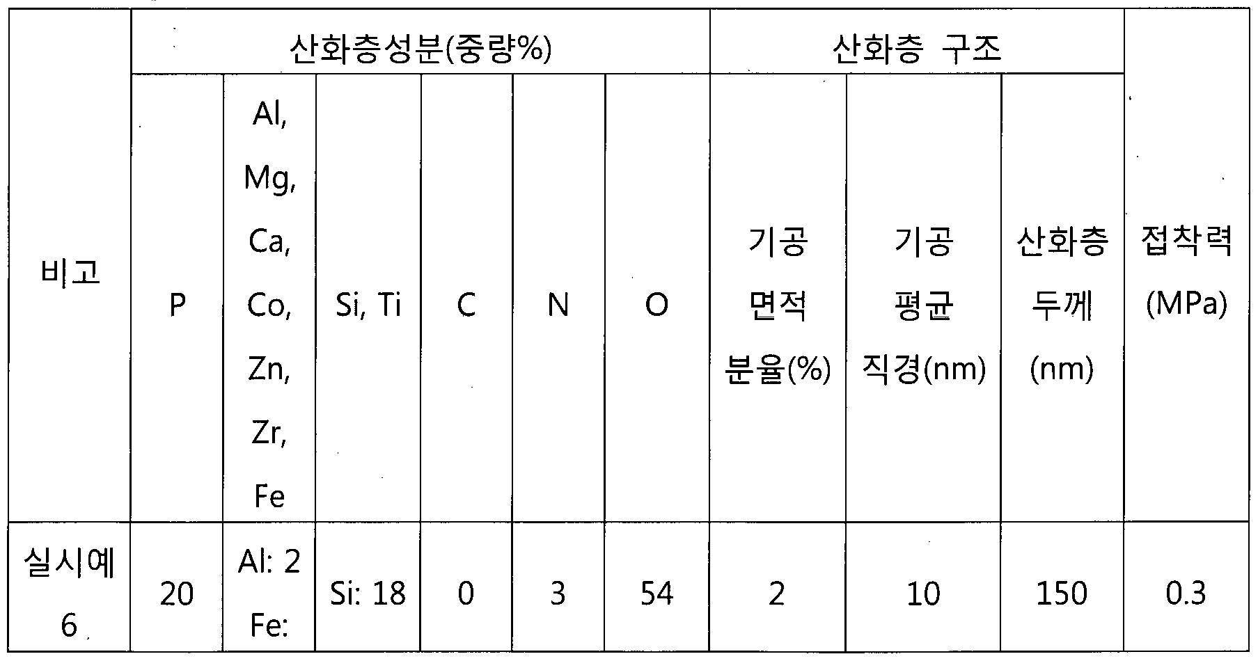

표 3내지 표 5에서 알수있듯이, 본원의 구성 성분및성분비율을 모두만족하는실시예 6내지 실시예 9는접착력이 모두우수함을확인할수 있다.
반면,비교예 7은접착코팅 조성물내에 인산의 함량이 적어,접착층
2019/132355 1»(:1^1{2018/016031
및산화층내에서 I3의 함량이 적어지고, 접착력이 열위하였다.
비교예 8은 접착코팅 조성물 내에 무기 나노 입자의 함량이 많아, 접착층 및 산화층 내에 의 함량이 과량으로 분석되었으며, 접착력이 열위하였다.
5 비교예 9 및 10은 금속 인산염 대신 유기 인산염인 페놀계 인산을 첨가한경우로서, 접착층 및 산화층에 기공 면적 분율이 매우높거나또는 기공의 직경이크게 형성되어, 접착력이 열위하였다.
본발명은상기 실시예들에 한정되는 것이 아니라서로다른다양한 형태로 제조될 수 있으며, 본 발명이 속하는 기술분야에서 통상의 지식을 10 가진 자는 본 발명의 기술적 사상이나 필수적인 특징을 변경하지 않고서 다른 구체적인 형태로 실시될 수 있다는 것을 이해할 수 있을 것이다. 그러므로 이상에서 기술한 실시예들은 모든 면에서 예시적인 것이며 한정적이 아닌것으로이해해야만한다.
【부호의 설명】
15 100 : 전기강판제품 10 : 전기강판
20 : 산화층 30 : 접착층
Claims
2019/132355 1»(:1^1{2018/016031
【청구범위】
【청구항 11
전체고형분 100중량%기준으로,
평균입경이 10내지 30011111인수지 20내지 40중량%;
상기 수지와결합된무기 나노입자 10내지 35중량%;
금속인산염 10내지 30중량%및 .
인산 10내지 40중량%을포함하고,
상기무기 나노입자는 02및 02중 1종이상을포함하고, 상기 금속인산염은사, 03 ,
 이상의 금속을 포함하는전기강판접착코팅 조성물.
【청구항 2]
제 1항에 있어서,
상기 무기 나노입자는 ^02를포함하는전기강판접착코팅 조성물.
【청구항 3】
제 1항에 있어서,
상기 금속인산염은시을포함하는전기강판접착코팅 조성물.
【청구항 4]
복수의 전기강판; 및
상기 복수의 전기강판사이에 위치하는접착층;을포함하고 , 상기 접착층은사, 1%, 03 , 00 , 1x1,社및 근중 1종이상의 금속: 0.5 내지 30중량%, 0.1내지 10중량%,(:: 0.1내지 5중량%,이내지 30중량%, ^ 및 중 1종이상의 금속: 10내지 30중량%및잔부 0를포함하고, 상기 접착층은, 접착층의 단면 면적에 대하여, 기공이 차지하는 면적의 분율이 10 내지 70%이고, 상기 기공의 평균 직경은 상기 접착층 두께의 20%이하인전기강판제품.
【청구항 5]
제 4항에 있어서,
상기 A\,}lg, Ca, 00 ,
 이상의 금속은시인 전기강판 제품.
【청구항 6]
2019/132355 1»(:1^1{2018/016031
제 4항에 있어서,
상기 및 중 1종이상의 금속은 인전기강판제품.
【청구항 7]
제 4항에 있어서,
상기 접착층의두께는 0.5내지 40 1인 전기강판제품.
【청구항 8]
제 4항에 있어서,
상기 전기강판 및 상기 접착층 사이에 위치하는 산화층을 더 포함하는전기강판제품.
【청구항 9】
제 8항에 있어서,
상기 산화층은사, 1結, 03 , 00 ,
 이상의 금속: 1내지 20중량%, : 0.1내지 10중량%, 0: 0.1중량%이하, 10내지 40중량%, 및 중 1종 이상의 금속: 5 내지 30 중량% 및 잔부 0를 포함하는 전기강판제품.
【청구항 10】
제 8항에 있어서,
상기 산화층은상기 산화층의 단면 면적에 대하여, 기공이 차지하는 면적의 분율이 10%이하인전기강판제품.
【청구항 11】
제 8항에 있어서,
상기산화층의 두께는 10내지 500™인 전기강판제품.
【청구항 12】
제 8항에 있어서,
상기 기공의 평균 직경은 상기 산화층 두께의 20% 이하인 전기강판 제품.
【청구항 13】
제 1항에 기재된접착코팅 조성물을준비하는단계;
상기 접착 코팅 조성물을 전기강판의 표면에 코팅한 후, 경화시켜 접착코팅층을형성하는단계;
2019/132355 1»(:1^1{2018/016031
상기 접착코팅층이 형성된 복수의 전기강판을적층하고, 열융착하여 열융착층을형성하는단계 ; 및
열융착된 전기강판 제품을응력 제거 소둔 하여, 접착층을 형성하는 단계;
5 를포함하는전기강판제품의 제조방법 .
Priority Applications (4)
| Application Number | Priority Date | Filing Date | Title |
|---|---|---|---|
| EP18894968.9A EP3733806A4 (en) | 2017-12-26 | 2018-12-17 | Electrical steel sheet adhesive coating composition, electrical steel sheet product, and manufacturing method therefor |
| JP2020536094A JP7037658B2 (ja) | 2017-12-26 | 2018-12-17 | 電磁鋼板接着コーティング組成物、電磁鋼板製品、およびその製造方法 |
| US16/958,137 US11613673B2 (en) | 2017-12-26 | 2018-12-17 | Electrical steel sheet adhesive coating composition, electrical steel sheet product, and manufacturing method therefor |
| CN201880084867.6A CN111542576B (zh) | 2017-12-26 | 2018-12-17 | 电工钢板粘合涂覆组合物、电工钢板产品及其制造方法 |
Applications Claiming Priority (2)
| Application Number | Priority Date | Filing Date | Title |
|---|---|---|---|
| KR10-2017-0180116 | 2017-12-26 | ||
| KR1020170180116A KR102112171B1 (ko) | 2017-12-26 | 2017-12-26 | 전기강판 접착 코팅 조성물, 전기강판 제품, 및 이의 제조 방법 |
Publications (1)
| Publication Number | Publication Date |
|---|---|
| WO2019132355A1 true WO2019132355A1 (ko) | 2019-07-04 |
Family
ID=67067831
Family Applications (1)
| Application Number | Title | Priority Date | Filing Date |
|---|---|---|---|
| PCT/KR2018/016031 Ceased WO2019132355A1 (ko) | 2017-12-26 | 2018-12-17 | 전기강판 접착 코팅 조성물, 전기강판 제품, 및 이의 제조방법 |
Country Status (6)
| Country | Link |
|---|---|
| US (1) | US11613673B2 (ko) |
| EP (1) | EP3733806A4 (ko) |
| JP (1) | JP7037658B2 (ko) |
| KR (1) | KR102112171B1 (ko) |
| CN (1) | CN111542576B (ko) |
| WO (1) | WO2019132355A1 (ko) |
Families Citing this family (3)
| Publication number | Priority date | Publication date | Assignee | Title |
|---|---|---|---|---|
| KR102114810B1 (ko) * | 2017-12-26 | 2020-05-25 | 주식회사 포스코 | 전기강판 접착 코팅 조성물, 전기강판 적층체 및 전기강판 제품의 제조 방법 |
| CN116685463A (zh) * | 2020-12-21 | 2023-09-01 | 浦项股份有限公司 | 自粘接用电工钢板以及包含其的层叠体 |
| KR20230095527A (ko) * | 2021-12-22 | 2023-06-29 | 주식회사 포스코 | 전기강판 절연 피막 조성물, 전기강판, 및 이의 제조 방법 |
Citations (6)
| Publication number | Priority date | Publication date | Assignee | Title |
|---|---|---|---|---|
| WO2011102328A1 (ja) * | 2010-02-18 | 2011-08-25 | 新日本製鐵株式会社 | 無方向性電磁鋼板及びその製造方法 |
| KR20140060717A (ko) * | 2012-11-12 | 2014-05-21 | 주식회사 포스코 | 절연피막 조성물, 이를 이용한 무방향성 전기강판의 절연피막 형성방법 및 무방향성 전기강판 |
| KR20140062535A (ko) * | 2012-11-12 | 2014-05-26 | 주식회사 포스코 | 절연피막 조성물, 이를 이용한 무방향성 전기강판의 절연피막 형성방법 및 무방향성 전기강판 |
| KR20150061472A (ko) * | 2013-11-27 | 2015-06-04 | 주식회사 포스코 | 무방향성 전기 강판 코팅 조성물, 무방향성 전기 강판 제품의 제조 방법 및 무방향성 전기 강판 제품 |
| KR101736627B1 (ko) * | 2015-12-22 | 2017-05-17 | 주식회사 포스코 | 철손이 낮고 절연특성이 우수한 방향성 전기강판 및 그 제조방법 |
| KR20170074110A (ko) * | 2015-12-21 | 2017-06-29 | 주식회사 포스코 | 무방향성 전기강판 접착 코팅 조성물, 무방향성 전기강판 제품, 및 이의 제조 방법 |
Family Cites Families (16)
| Publication number | Priority date | Publication date | Assignee | Title |
|---|---|---|---|---|
| US6159534A (en) * | 1998-11-23 | 2000-12-12 | Nippon Steel Corporation | Method for producing non-oriented electromagnetic steel sheet having insulating film excellent in film properties |
| JP4700286B2 (ja) | 2004-02-27 | 2011-06-15 | 新日本製鐵株式会社 | 絶縁被膜特性の良好な無方向性電磁鋼板 |
| KR100886236B1 (ko) | 2004-10-18 | 2009-03-02 | 신닛뽄세이테쯔 카부시키카이샤 | 내열 접착성 절연 피막 |
| KR101264231B1 (ko) | 2009-12-23 | 2013-05-22 | 주식회사 포스코 | 절연성이 우수한 절연피막 형성용 피복조성물, 이를 이용한 무방향성 전기강판 및 무방향성 전기강판의 절연피막 형성방법 |
| JP5741190B2 (ja) * | 2010-05-17 | 2015-07-01 | Jfeスチール株式会社 | 半有機絶縁被膜付き電磁鋼板 |
| EP2799594B1 (en) | 2011-12-28 | 2018-10-31 | JFE Steel Corporation | Directional electromagnetic steel sheet with coating, and method for producing same |
| KR101324260B1 (ko) | 2011-12-28 | 2013-11-01 | 주식회사 포스코 | 무방향성 전기강판의 절연 피막 조성물, 그 제조방법 및 절연 피막조성물이 적용된 무방향성 전기강판 |
| JP6176181B2 (ja) | 2014-04-22 | 2017-08-09 | Jfeスチール株式会社 | 積層電磁鋼板およびその製造方法 |
| KR102444224B1 (ko) | 2015-12-23 | 2022-09-16 | 주식회사 포스코 | 무방향성 전기강판 접착 코팅 조성물, 무방향성 전기강판 제품, 및 이의 제조 방법 |
| JP6682892B2 (ja) | 2016-02-08 | 2020-04-15 | 日本製鉄株式会社 | 電磁鋼板及び電磁鋼板の製造方法 |
| JP1571838S (ko) | 2016-05-17 | 2017-03-21 | ||
| KR101904306B1 (ko) | 2016-12-23 | 2018-10-04 | 주식회사 포스코 | 무방향성 전기강판 접착 코팅 조성물 및 무방향성 전기강판 제품의 제조 방법 |
| US11807922B2 (en) | 2016-12-23 | 2023-11-07 | Posco Co., Ltd | Electrical steel sheet adhesive coating composition, electrical steel sheet product, and manufacturing method therefor |
| KR102091123B1 (ko) | 2017-12-26 | 2020-03-19 | 주식회사 포스코 | 전기강판 제품 및 전기강판 제품의 제조 방법 |
| KR102033029B1 (ko) | 2017-12-26 | 2019-10-16 | 주식회사 포스코 | 전기강판 적층체, 및 이의 제조 방법 |
| KR102114810B1 (ko) | 2017-12-26 | 2020-05-25 | 주식회사 포스코 | 전기강판 접착 코팅 조성물, 전기강판 적층체 및 전기강판 제품의 제조 방법 |
-
2017
- 2017-12-26 KR KR1020170180116A patent/KR102112171B1/ko active Active
-
2018
- 2018-12-17 EP EP18894968.9A patent/EP3733806A4/en active Pending
- 2018-12-17 JP JP2020536094A patent/JP7037658B2/ja active Active
- 2018-12-17 WO PCT/KR2018/016031 patent/WO2019132355A1/ko not_active Ceased
- 2018-12-17 US US16/958,137 patent/US11613673B2/en active Active
- 2018-12-17 CN CN201880084867.6A patent/CN111542576B/zh active Active
Patent Citations (6)
| Publication number | Priority date | Publication date | Assignee | Title |
|---|---|---|---|---|
| WO2011102328A1 (ja) * | 2010-02-18 | 2011-08-25 | 新日本製鐵株式会社 | 無方向性電磁鋼板及びその製造方法 |
| KR20140060717A (ko) * | 2012-11-12 | 2014-05-21 | 주식회사 포스코 | 절연피막 조성물, 이를 이용한 무방향성 전기강판의 절연피막 형성방법 및 무방향성 전기강판 |
| KR20140062535A (ko) * | 2012-11-12 | 2014-05-26 | 주식회사 포스코 | 절연피막 조성물, 이를 이용한 무방향성 전기강판의 절연피막 형성방법 및 무방향성 전기강판 |
| KR20150061472A (ko) * | 2013-11-27 | 2015-06-04 | 주식회사 포스코 | 무방향성 전기 강판 코팅 조성물, 무방향성 전기 강판 제품의 제조 방법 및 무방향성 전기 강판 제품 |
| KR20170074110A (ko) * | 2015-12-21 | 2017-06-29 | 주식회사 포스코 | 무방향성 전기강판 접착 코팅 조성물, 무방향성 전기강판 제품, 및 이의 제조 방법 |
| KR101736627B1 (ko) * | 2015-12-22 | 2017-05-17 | 주식회사 포스코 | 철손이 낮고 절연특성이 우수한 방향성 전기강판 및 그 제조방법 |
Non-Patent Citations (1)
| Title |
|---|
| See also references of EP3733806A4 * |
Also Published As
| Publication number | Publication date |
|---|---|
| US20200362202A1 (en) | 2020-11-19 |
| KR20190078282A (ko) | 2019-07-04 |
| JP2021510181A (ja) | 2021-04-15 |
| US11613673B2 (en) | 2023-03-28 |
| JP7037658B2 (ja) | 2022-03-16 |
| KR102112171B1 (ko) | 2020-05-18 |
| CN111542576A (zh) | 2020-08-14 |
| EP3733806A1 (en) | 2020-11-04 |
| CN111542576B (zh) | 2021-11-30 |
| EP3733806A4 (en) | 2021-06-30 |
Similar Documents
| Publication | Publication Date | Title |
|---|---|---|
| KR101904306B1 (ko) | 무방향성 전기강판 접착 코팅 조성물 및 무방향성 전기강판 제품의 제조 방법 | |
| KR102178811B1 (ko) | 전기강판 접착 코팅 조성물, 전기강판 제품, 및 이의 제조 방법 | |
| KR20190077985A (ko) | 전기강판 적층체, 및 이의 제조 방법 | |
| JP6626978B2 (ja) | 無方向性電磁鋼板接着コーティング組成物、無方向性電磁鋼板製品、及びその製造方法 | |
| KR102444224B1 (ko) | 무방향성 전기강판 접착 코팅 조성물, 무방향성 전기강판 제품, 및 이의 제조 방법 | |
| WO2019132365A1 (ko) | 전기강판 접착 코팅 조성물, 전기강판 적층체 및 전기강판 제품의 제조방법 | |
| JP5272688B2 (ja) | クラッド型電磁鋼板 | |
| WO2015080463A1 (ko) | 무방향성 전기 강판 조성물, 무방향성 전기 강판 제품의 제조 방법 및 무방향성 전기 강판 제품 | |
| WO2019132355A1 (ko) | 전기강판 접착 코팅 조성물, 전기강판 제품, 및 이의 제조방법 | |
| JP7603759B2 (ja) | 軟磁性粉末及び圧粉磁心 | |
| JP2022501234A (ja) | 電磁鋼板積層体 | |
| JP2000173815A (ja) | 積層鉄心用接着鋼板 | |
| KR102091123B1 (ko) | 전기강판 제품 및 전기강판 제품의 제조 방법 |
Legal Events
| Date | Code | Title | Description |
|---|---|---|---|
| 121 | Ep: the epo has been informed by wipo that ep was designated in this application |
Ref document number: 18894968 Country of ref document: EP Kind code of ref document: A1 |
|
| ENP | Entry into the national phase |
Ref document number: 2020536094 Country of ref document: JP Kind code of ref document: A |
|
| NENP | Non-entry into the national phase |
Ref country code: DE |
|
| ENP | Entry into the national phase |
Ref document number: 2018894968 Country of ref document: EP Effective date: 20200727 |