WO2019134100A1 - 功率控制的方法、终端设备和网络设备 - Google Patents
功率控制的方法、终端设备和网络设备 Download PDFInfo
- Publication number
- WO2019134100A1 WO2019134100A1 PCT/CN2018/071394 CN2018071394W WO2019134100A1 WO 2019134100 A1 WO2019134100 A1 WO 2019134100A1 CN 2018071394 W CN2018071394 W CN 2018071394W WO 2019134100 A1 WO2019134100 A1 WO 2019134100A1
- Authority
- WO
- WIPO (PCT)
- Prior art keywords
- value
- srs resource
- terminal device
- power control
- control parameter
- Prior art date
- Legal status (The legal status is an assumption and is not a legal conclusion. Google has not performed a legal analysis and makes no representation as to the accuracy of the status listed.)
- Ceased
Links
Images


Classifications
-
- H—ELECTRICITY
- H04—ELECTRIC COMMUNICATION TECHNIQUE
- H04W—WIRELESS COMMUNICATION NETWORKS
- H04W52/00—Power management, e.g. Transmission Power Control [TPC] or power classes
- H04W52/04—Transmission power control [TPC]
- H04W52/06—TPC algorithms
- H04W52/14—Separate analysis of uplink or downlink
- H04W52/146—Uplink power control
-
- H—ELECTRICITY
- H04—ELECTRIC COMMUNICATION TECHNIQUE
- H04L—TRANSMISSION OF DIGITAL INFORMATION, e.g. TELEGRAPHIC COMMUNICATION
- H04L25/00—Baseband systems
- H04L25/02—Details ; arrangements for supplying electrical power along data transmission lines
- H04L25/0202—Channel estimation
- H04L25/0224—Channel estimation using sounding signals
- H04L25/0226—Channel estimation using sounding signals sounding signals per se
-
- H—ELECTRICITY
- H04—ELECTRIC COMMUNICATION TECHNIQUE
- H04L—TRANSMISSION OF DIGITAL INFORMATION, e.g. TELEGRAPHIC COMMUNICATION
- H04L5/00—Arrangements affording multiple use of the transmission path
- H04L5/003—Arrangements for allocating sub-channels of the transmission path
- H04L5/0044—Allocation of payload; Allocation of data channels, e.g. PDSCH or PUSCH
-
- H—ELECTRICITY
- H04—ELECTRIC COMMUNICATION TECHNIQUE
- H04L—TRANSMISSION OF DIGITAL INFORMATION, e.g. TELEGRAPHIC COMMUNICATION
- H04L5/00—Arrangements affording multiple use of the transmission path
- H04L5/003—Arrangements for allocating sub-channels of the transmission path
- H04L5/0048—Allocation of pilot signals, i.e. of signals known to the receiver
-
- H—ELECTRICITY
- H04—ELECTRIC COMMUNICATION TECHNIQUE
- H04L—TRANSMISSION OF DIGITAL INFORMATION, e.g. TELEGRAPHIC COMMUNICATION
- H04L5/00—Arrangements affording multiple use of the transmission path
- H04L5/003—Arrangements for allocating sub-channels of the transmission path
- H04L5/0048—Allocation of pilot signals, i.e. of signals known to the receiver
- H04L5/0051—Allocation of pilot signals, i.e. of signals known to the receiver of dedicated pilots, i.e. pilots destined for a single user or terminal
-
- H—ELECTRICITY
- H04—ELECTRIC COMMUNICATION TECHNIQUE
- H04L—TRANSMISSION OF DIGITAL INFORMATION, e.g. TELEGRAPHIC COMMUNICATION
- H04L5/00—Arrangements affording multiple use of the transmission path
- H04L5/0091—Signalling for the administration of the divided path, e.g. signalling of configuration information
- H04L5/0094—Indication of how sub-channels of the path are allocated
-
- H—ELECTRICITY
- H04—ELECTRIC COMMUNICATION TECHNIQUE
- H04W—WIRELESS COMMUNICATION NETWORKS
- H04W52/00—Power management, e.g. Transmission Power Control [TPC] or power classes
- H04W52/04—Transmission power control [TPC]
- H04W52/18—TPC being performed according to specific parameters
- H04W52/24—TPC being performed according to specific parameters using SIR [Signal to Interference Ratio] or other wireless path parameters
- H04W52/242—TPC being performed according to specific parameters using SIR [Signal to Interference Ratio] or other wireless path parameters taking into account path loss
-
- H—ELECTRICITY
- H04—ELECTRIC COMMUNICATION TECHNIQUE
- H04W—WIRELESS COMMUNICATION NETWORKS
- H04W52/00—Power management, e.g. Transmission Power Control [TPC] or power classes
- H04W52/04—Transmission power control [TPC]
- H04W52/30—Transmission power control [TPC] using constraints in the total amount of available transmission power
- H04W52/36—Transmission power control [TPC] using constraints in the total amount of available transmission power with a discrete range or set of values, e.g. step size, ramping or offsets
-
- H—ELECTRICITY
- H04—ELECTRIC COMMUNICATION TECHNIQUE
- H04W—WIRELESS COMMUNICATION NETWORKS
- H04W52/00—Power management, e.g. Transmission Power Control [TPC] or power classes
- H04W52/04—Transmission power control [TPC]
- H04W52/30—Transmission power control [TPC] using constraints in the total amount of available transmission power
- H04W52/36—Transmission power control [TPC] using constraints in the total amount of available transmission power with a discrete range or set of values, e.g. step size, ramping or offsets
- H04W52/367—Power values between minimum and maximum limits, e.g. dynamic range
-
- H—ELECTRICITY
- H04—ELECTRIC COMMUNICATION TECHNIQUE
- H04W—WIRELESS COMMUNICATION NETWORKS
- H04W72/00—Local resource management
- H04W72/04—Wireless resource allocation
- H04W72/044—Wireless resource allocation based on the type of the allocated resource
- H04W72/0473—Wireless resource allocation based on the type of the allocated resource the resource being transmission power
-
- H—ELECTRICITY
- H04—ELECTRIC COMMUNICATION TECHNIQUE
- H04W—WIRELESS COMMUNICATION NETWORKS
- H04W72/00—Local resource management
- H04W72/12—Wireless traffic scheduling
- H04W72/1263—Mapping of traffic onto schedule, e.g. scheduled allocation or multiplexing of flows
- H04W72/1268—Mapping of traffic onto schedule, e.g. scheduled allocation or multiplexing of flows of uplink data flows
-
- H—ELECTRICITY
- H04—ELECTRIC COMMUNICATION TECHNIQUE
- H04W—WIRELESS COMMUNICATION NETWORKS
- H04W72/00—Local resource management
- H04W72/20—Control channels or signalling for resource management
- H04W72/21—Control channels or signalling for resource management in the uplink direction of a wireless link, i.e. towards the network
-
- H—ELECTRICITY
- H04—ELECTRIC COMMUNICATION TECHNIQUE
- H04W—WIRELESS COMMUNICATION NETWORKS
- H04W72/00—Local resource management
- H04W72/20—Control channels or signalling for resource management
- H04W72/23—Control channels or signalling for resource management in the downlink direction of a wireless link, i.e. towards a terminal
Definitions
- the embodiments of the present application relate to the field of communications, and in particular, to a method, a terminal device, and a network device for power control.
- a terminal may have multiple antenna array panels for uplink transmission, a panel containing a set of physical antennas, and each panel may have independent RF channels.
- the terminal can transmit data on multiple panels at the same time.
- different panels need to adopt different transmission parameters according to respective channel information, such as transmission power.
- SRS Sounding Reference Signal
- a panel may correspond to one SRS resource set, and the network side may be indicated by an SRS Resource Indicator.
- SRS Resource Indicator A collection of SRS resources. If the data transmission on the panel is scheduled by the DCI, there is an SRI indication of the corresponding panel in a DCI. At this time, how the terminal device determines the transmission power of the uplink transmission corresponding to the SRI is a problem.
- the embodiments of the present application provide a power control method, a terminal device, and a network device, which are beneficial to achieve higher spectrum efficiency.
- a method for power control includes: receiving, by a terminal device, downlink control information DCI, which is sent by a network device, for scheduling a physical uplink shared channel (PUSCH), where the DCI includes a first sounding reference signal SRS resource indication; The terminal device determines, according to the DCI, a value of an uplink power control parameter corresponding to the first SRS resource indication; the terminal device determines, according to the value of the uplink power control parameter corresponding to the first SRS resource indication, the PUSCH bearer The actual transmit power of the first uplink data corresponding to the first SRS resource indication.
- DCI downlink control information
- PUSCH physical uplink shared channel
- the method further includes: receiving, by the terminal device, first configuration information that is sent by the network device, where the first configuration information is used to indicate the first SRS resource. Corresponding relationship between the value of the indication and the value of the uplink power control parameter; the terminal device determines, according to the DCI, a value of the uplink power control parameter corresponding to the first SRS resource indication, including: the terminal device according to the DCI The value of the first SRS resource indication and the corresponding relationship determine a value of an uplink power control parameter corresponding to the first SRS resource indication.
- the network device may not configure the corresponding relationship, or the corresponding relationship may be agreed by the protocol.
- the first SRS resource indication may also be a candidate value of the multiple sets of uplink power control parameters
- the terminal device may determine, according to the candidate values of the multiple sets of uplink power control parameters corresponding to the first SRS resource indication, a set of uplink power. The value of the control parameter.
- the terminal device determines, according to the DCI, a value of an uplink power control parameter corresponding to the first SRS resource indication, where the terminal device determines, according to the DCI, the first SRS resource indication.
- the terminal device determines, according to the value of the uplink power control parameter, the actual transmit power of the first uplink data that is corresponding to the first SRS resource indication that is sent by the PUSCH, and includes: the terminal device according to the And determining, by the value of the maximum transmit power corresponding to the first SRS resource indication, the actual transmit power of the first uplink data.
- the terminal device determines, according to the DCI, a value of the maximum transmit power corresponding to the first SRS resource indication, where the terminal device determines, according to the number of SRS resource indications included in the DCI, The value of the maximum transmission power corresponding to the first SRS resource indication.
- the terminal device determines, according to the DCI, a value of the maximum transmit power corresponding to the first SRS resource indication, including: the terminal device according to the first SRS resource indication included in the DCI. And determining, by the number of the SRS resources, a value of the maximum transmit power corresponding to the first SRS resource indication.
- the terminal device determines, according to the value of the uplink power control parameter corresponding to the first SRS resource indication, the actual uplink data corresponding to the first resource SRS indication carried by the PUSCH. Transmitting power, comprising: determining, by the terminal device, an initial transmit power of the first uplink data according to the value of the uplink power control parameter corresponding to the first SRS resource indication; the initial transmit power of the terminal device according to the first uplink data The total initial transmit power of the uplink data carried by the PUSCH and the uplink maximum transmit power of the terminal device determine the actual transmit power of the first uplink data.
- the DCI further includes a second SRS resource indication, where the first SRS resource indication and the second SRS resource indication respectively correspond to values of independent uplink power control parameters.
- the method before the terminal device receives the DCI sent by the network device, the method further includes: receiving, by the terminal device, second configuration information sent by the network device, where the second configuration information is used to indicate the The value of the uplink power control parameter corresponding to the value of the second SRS resource indication, where the value of the uplink power control parameter corresponding to the value indicated by the second SRS resource and the uplink power corresponding to the value indicated by the first SRS resource
- the value of the control parameter is independently configured by the network device.
- the uplink power control parameter includes a path loss value used to determine a transmit power of the uplink data or a downlink signal used to measure the path loss value.
- the uplink power control parameter includes an open loop power control parameter and/or a closed loop power control parameter.
- the first uplink data is a part of data carried by the PUSCH.
- the method further includes: the terminal device sending the first uplink data to the network device according to the actual transmit power.
- a method for power control includes: the network device sending, to the terminal device, downlink control information DCI for scheduling a physical uplink shared channel (PUSCH), where the DCI includes a first sounding reference signal SRS resource indication, where The DCI is used by the terminal device to determine a value of the uplink power control parameter corresponding to the first SRS resource indication, so that the terminal device determines the PUSCH bearer according to the value of the uplink power control parameter corresponding to the first SRS resource indication.
- the method before the network device sends the DCI to the terminal device, the method further includes: the network device sending, to the terminal device, first configuration information, where the first configuration information is used to indicate the first Correspondence between the value of an SRS resource indication and the value of the uplink power control parameter.
- the DCI further includes a second SRS resource indication, where the first SRS resource indication and the second SRS resource indication respectively correspond to values of independent uplink power control parameters.
- the method before the network device sends the DCI to the terminal device, the method further includes: the network device sending second configuration information to the terminal device, where the second configuration information is used to indicate the first The value of the uplink power control parameter corresponding to the value of the second SRS resource indication, where the value of the uplink power control parameter corresponding to the value indicated by the second SRS resource and the uplink power control corresponding to the value indicated by the first SRS resource The value of the parameter is configured independently by the network device.
- the uplink power control parameter includes a path loss value used to determine a transmit power of the uplink data or a downlink signal used to measure the path loss value.
- the uplink power control parameter includes an open loop power control parameter and/or a closed loop power control parameter.
- the first uplink data is a part of data carried by the PUSCH.
- the method further includes: receiving, by the network device, the first uplink data that is sent by the terminal device according to the actual transmit power.
- a terminal device for performing the method of any of the above first aspect or any of the possible implementations of the first aspect.
- the terminal device comprises means for performing the method of any of the above-described first aspect or any of the possible implementations of the first aspect.
- a network device for performing the method of any of the foregoing second aspect or any of the possible implementations of the second aspect.
- the network device comprises means for performing the method of any of the above-described second or second aspects of the second aspect.
- a terminal device comprising: a memory, a processor, an input interface, and an output interface.
- the memory, the processor, the input interface, and the output interface are connected by a bus system.
- the memory is for storing instructions for executing the memory stored instructions for performing the method of any of the first aspect or the first aspect of the first aspect.
- a network device comprising: a memory, a processor, an input interface, and an output interface.
- the memory, the processor, the input interface, and the output interface are connected by a bus system.
- the memory is for storing instructions for executing the memory stored instructions for performing the method of any of the above-described second aspect or any of the possible implementations of the second aspect.
- a computer storage medium for storing the method in any of the above possible implementations of the first aspect or the first aspect, or any possible implementation of the second or second aspect
- Computer software instructions for use in the method of the present invention including programs designed to perform the various aspects described above.
- a computer program product comprising instructions, when executed on a computer, causes the computer to perform the method of any of the first aspect or the optional implementation of the first aspect, or the second Aspect or method of any alternative implementation of the second aspect.
- FIG. 1 is a schematic diagram of an application scenario of an embodiment of the present application.
- FIG. 2 is a schematic block diagram showing a method of uplink power in the embodiment of the present application.
- FIG. 3 is another schematic block diagram of a method for uplink power in the embodiment of the present application.
- FIG. 4 shows a schematic block diagram of a terminal device of an embodiment of the present application.
- FIG. 5 shows a schematic block diagram of a network device of an embodiment of the present application.
- FIG. 6 shows another schematic block diagram of a terminal device according to an embodiment of the present application.
- FIG. 7 shows another schematic block diagram of a network device of an embodiment of the present application.
- GSM Global System of Mobile communication
- CDMA Code Division Multiple Access
- WCDMA Wideband Code Division Multiple Access
- GPRS General Packet Radio Service
- LTE Long Term Evolution
- FDD Frequency Division Duplex
- TDD Time Division duplex
- UMTS Universal Mobile Telecommunication System
- WiMAX Worldwide Interoperability for Microwave Access
- the technical solutions of the embodiments of the present application can be applied to various communication systems based on non-orthogonal multiple access technologies, such as a sparse code multiple access (SCMA) system, and a low-density signature (Low). Density Signature (LDS) system, etc., of course, the SCMA system and the LDS system may also be referred to as other names in the communication field; further, the technical solution of the embodiment of the present application can be applied to multi-carrier using non-orthogonal multiple access technology.
- SCMA sparse code multiple access
- LDS Density Signature
- Orthogonal Frequency Division Multiplexing OFDM
- Filter Bank Multi-Carrier FBMC
- General Frequency Division Multiplexing Generalized Frequency Division Multiplexing (OFDM)) Frequency Division Multiplexing (GFDM)
- Filtered Orthogonal Frequency Division Multiplexing Filtered-OFDM, F-OFDM
- the terminal device in the embodiment of the present application may refer to a user equipment (User Equipment, UE), an access terminal, a subscriber unit, a subscriber station, a mobile station, a mobile station, a remote station, a remote terminal, a mobile device, a user terminal, a terminal, and a wireless device.
- Communication device user agent or user device.
- the access terminal may be a cellular phone, a cordless phone, a Session Initiation Protocol (SIP) phone, a Wireless Local Loop (WLL) station, a Personal Digital Assistant (PDA), with wireless communication.
- SIP Session Initiation Protocol
- WLL Wireless Local Loop
- PDA Personal Digital Assistant
- the network device in the embodiment of the present application may be a device for communicating with a terminal device, where the network device may be a Base Transceiver Station (BTS) in GSM or CDMA, or may be a base station (NodeB, NB) in a WCDMA system. And may be an evolved base station (eNB or eNodeB) in the LTE system, or may be a wireless controller in a cloud radio access network (CRAN) scenario, or the network device may be The embodiments of the present application are not limited to the relay station, the access point, the in-vehicle device, the wearable device, and the network device in the future 5G network or the network device in the future evolved PLMN network.
- BTS Base Transceiver Station
- NodeB NodeB
- NB base station
- CRAN cloud radio access network
- the embodiments of the present application are not limited to the relay station, the access point, the in-vehicle device, the wearable device, and the network device in the future 5G network or
- FIG. 1 is a schematic diagram of an application scenario of an embodiment of the present application.
- the communication system in FIG. 1 may include a terminal device 10 and a network device 20.
- the network device 20 is configured to provide communication services for the terminal device 10 and access the core network.
- the terminal device 10 accesses the network by searching for synchronization signals, broadcast signals, and the like transmitted by the network device 20, thereby performing communication with the network.
- the arrows shown in FIG. 1 may represent uplink/downlink transmissions by a cellular link between the terminal device 10 and the network device 20.
- the terminal can have multiple panels for uplink transmission, one panel contains a set of physical antennas, and each panel can have independent RF channels.
- the terminal can transmit data on multiple panels at the same time.
- different panels need to adopt different transmission parameters according to respective channel information, such as transmission power.
- different SRS resources need to be configured for different panels.
- a panel may correspond to one SRS resource set, and the network side may indicate an SRS resource set by using an SRS resource indicator.
- the terminal may obtain the power control parameter corresponding to the uplink transmission according to the SRS resource indicated by the SRI or the SRI, so as to obtain the transmission power of the corresponding uplink data.
- the transmit power of the Physical Uplink Shared Channel can be calculated by the following formula:
- M PUSCH,c (i) is the number of Resource Blocks (RBs) occupied by the PUSCH;
- P CMAX,c (i) is the maximum transmission power of the subframe i on the serving cell c configured by the terminal device;
- P O_PUSCH,c ( j) and ⁇ c (j) are open loop power control parameters, which are values determined by the terminal equipment through higher layer signaling;
- PL c is a path loss value of the serving cell c measured by the terminal device to the terminal device;
- ⁇ TF,c (i) a value determined by the terminal device according to a ratio of the number of uplink data bits transmitted by the PUSCH to the number of resource units included in the PUSCH;
- f c (i, l) is a closed loop power control adjustment factor, which is determined by the terminal device The value determined
- FIG. 2 shows a schematic block diagram of a method 100 of power control in an embodiment of the present application. As shown in FIG. 2, the method 100 includes:
- the terminal device receives, by the network device, downlink control information DCI for scheduling a physical uplink shared channel (PUSCH), where the DCI includes a first sounding reference signal resource indication SRI;
- DCI includes a first sounding reference signal resource indication SRI;
- the terminal device determines, according to the DCI, a value of an uplink power control parameter corresponding to the first SRI.
- the terminal device determines, according to the value of the uplink power control parameter corresponding to the first SRI, an actual transmit power of the first uplink data corresponding to the first SRI that is carried by the PUSCH.
- the Downlink Control Information may further include a second SRI, where the first SRI and the second SRI respectively correspond to values of independent uplink power control parameters.
- the network device may pre-configure the value of the uplink power control parameter corresponding to the first SRI and the second SRI for the terminal device, for example, the network device may pre-configure the correspondence between the SRI and the value of the uplink power control parameter.
- the network device may carry the first SRI and the second SRI in the DCI for scheduling the PUSCH, so that the terminal device can determine the value of the uplink power control parameter corresponding to each SRI according to the DCI, and thus can determine each The actual transmit power of the uplink data corresponding to the SRI.
- the network device may pre-configure the value of ⁇ j, k, l ⁇ corresponding to each SRI through high-layer signaling, and different values may obtain values of different uplink power control parameters, and therefore, each The SRI can correspond to the value of a set of uplink power control parameters.
- the method of power control in the embodiments of the present application is advantageous for achieving higher spectral efficiency.
- the method further includes: receiving, by the terminal device, the first configuration information that is sent by the network device, where the first configuration information is used to indicate the value of the first SRI and the uplink power. Determining a value of the value of the control parameter; the terminal device determining, according to the DCI, a value of the uplink power control parameter corresponding to the first SRI, including: the terminal device according to the value of the first SRI included in the DCI, and The correspondence determines a value of an uplink power control parameter corresponding to the first SRI.
- the method further includes: receiving, by the terminal device, second configuration information that is sent by the network device, where the second configuration information is used to indicate that the second SRI is obtained.
- the value of the uplink power control parameter corresponding to the value wherein the value of the uplink power control parameter corresponding to the value of the second SRI and the value of the uplink power control parameter corresponding to the value of the first SRI are independently configured by the network device.
- the network device can pre-configure the correspondence between the value of the SRI and the value of the uplink power control parameter for the terminal device, and indicate to the terminal device by using high-layer signaling, such as Radio Resource Control (RRC).
- RRC Radio Resource Control
- the correspondence may be agreed by the agreement.
- the corresponding relationship may be a direct mapping relationship between the SRI and the value of the uplink power control parameter, or may be an indirect mapping relationship.
- the corresponding relationship may also be the number of SRS resources and the uplink power control parameter indicated by the SRI.
- the mapping between the values of the present application is not limited thereto.
- the first SRI and the second SRI may also correspond to independent uplink power control parameter candidate values.
- the first SRI and the second SRI are both 2 bits, and can respectively correspond to values of four possible uplink power control parameters.
- the first SRI and the second SRI may be independently configured by the network side, may be configured to different values, or may be configured to the same value.
- the uplink power control parameter includes information about a path loss value used to determine the transmit power of the uplink data or a downlink signal used to measure the path loss value.
- the downlink signal may be a Synchronous Signal Block (SSB) or a Channel State Information-Reference Signals (CSI-RS).
- the information of the downlink signal may be an index of a target downlink reference signal used for measuring the path loss value in the plurality of downlink reference signals that are configured in advance by the network side, for example, k in the above formula. That is, the terminal device may determine the index k of the corresponding downlink signal according to the value of the first SRI, and perform downlink path loss measurement based on the downlink signal indicated by the index k, thereby obtaining the path loss value.
- the uplink power control parameter includes an open loop power control parameter and/or a closed loop power control parameter.
- the value of the open loop power control parameter may be the indication information of the target power Po, the indication information of the path loss factor a, or the indication information of the closed loop power adjustment function f(i).
- the value of the open loop power control parameter may be an index of one of the plurality of target powers Po configured in advance on the network side, for example, j in the above formula, or may be a plurality of path loss factors a preconfigured on the network side.
- An index of one of the values, such as j in the above formula may also be a process index of closed-loop power control, such as l in the above formula.
- the terminal device determines, according to the DCI, a value of an uplink power control parameter corresponding to the first SRI, where the terminal device determines, according to the DCI, a value of a maximum transmit power corresponding to the first SRI;
- the terminal device determines, according to the value of the uplink power control parameter, the actual transmit power of the first uplink data corresponding to the first SRI that is carried by the PUSCH, and includes: the terminal device according to the maximum transmit power corresponding to the first SRI The value determines the actual transmit power of the first uplink data.
- the terminal device may determine a value of a maximum transmit power corresponding to each SRI in the DCI according to the DCI, and then determine, according to a value of a maximum transmit power corresponding to each SRI and a calculation formula of an uplink transmit power, each SRI corresponding The actual transmit power of the upstream data.
- the terminal device determines, according to the DCI, a value of the maximum transmit power corresponding to the first SRI, where the terminal device determines, according to the number of SRIs included in the DCI, the maximum corresponding to the first SRI.
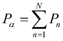
- the value of the transmit power For example, if the DCI includes N SRI indications, the maximum transmit power of the uplink data transmission corresponding to each SRI indication (including the first SRI) is P c,max /N, where P c,max is the total supported by the terminal. Maximum transmit power.
- the terminal device determines, according to the DCI, the value of the maximum transmit power corresponding to the first SRI, where the terminal device determines the number according to the number of SRS resources indicated by the first SRI included in the DCI.
- the value of the maximum transmission power corresponding to the first SRI For example, if the SRI indicates M SRS resources, and the total number of SRS resources indicated by all SRIs included in the DCI is N, the maximum transmit power of the uplink data transmission corresponding to the SRI is M*P c,max / N, where P c,max is the total maximum transmit power supported by the terminal.
- the maximum transmit power of the uplink data transmission corresponding to the first SRI is P c,max /2. If the first SRI indicates more than one SRS resource, the maximum transmit power of the uplink data transmission corresponding to the first SRI is P c,max . Where P c,max is the total maximum transmit power supported by the terminal. It is assumed here that the terminal supports up to two panels, and the multi-layer transmission is transmitted on multiple panels.
- the terminal device determines, according to the value of the uplink power control parameter that is corresponding to the first SRS resource indication, the actual transmit power of the first uplink data that is corresponding to the first resource SRS indication that is sent by the PUSCH, and includes: Determining, by the terminal device, an initial transmit power of the first uplink data according to the value of the uplink power control parameter corresponding to the first SRS resource indication; the terminal device according to the initial transmit power of the first uplink data, and the PUSCH bearer The total initial transmit power of the uplink data and the uplink maximum transmit power of the terminal device determine the actual transmit power of the first uplink data.
- the first uplink data is a part of data carried by the PUSCH.
- the uplink data is part of the data carried by the PUSCH scheduled by the DCI, for example, a part of the data transmission layer of the multiple data transmission layers carried by the PUSCH.
- the terminal needs to determine a corresponding SRI for each part of the data to be transmitted. Perform power control of this data. For example, if the PUSCH carries two layers of data transmission, one SRI may be indicated for each layer of data; if the PUSCH carries four layers of data transmission, one SRI may be indicated for every two layers of data.
- the terminal needs to provide a data transmission layer according to the solution provided by the application. Both determine their actual transmit power.
- the method further includes: the terminal device sending the first uplink data to the network device according to the actual transmit power.
- the actual transmit power calculated by the terminal is not actually used to send the uplink data, and may also be used to calculate the power headroom report (PHR) of the current PUSCH and report it to the network side, or as a reference. Calculate the transmit power of other upstream signals. For example, the terminal may obtain the transmit power of the SRS according to the actual transmit power of the calculated uplink data, plus a certain offset value, and the uplink data transmission may not actually exist at this time.
- PHR power headroom report
- FIG. 3 shows a schematic block diagram of a method 200 of power control in accordance with an embodiment of the present application. As shown in FIG. 3, the method 200 includes some or all of the following:
- the network device sends downlink control information DCI for scheduling a physical uplink shared channel (PUSCH) to the terminal device, where the DCI includes a first sounding reference signal resource indication SRI, where the DCI is used by the terminal device to determine an uplink corresponding to the first SRI. a value of the power control parameter, so that the terminal device determines the actual transmit power of the first uplink data corresponding to the first SRI that is carried by the PUSCH according to the value of the uplink power control parameter corresponding to the first SRI.
- PUSCH physical uplink shared channel
- the method of power control in the embodiments of the present application is advantageous for achieving higher spectral efficiency.
- the method before the network device sends the DCI to the terminal device, the method further includes: the network device sending, to the terminal device, first configuration information, where the first configuration information is used to indicate Correspondence between the value of the first SRI and the value of the uplink power control parameter.
- the method before the network device sends the DCI to the terminal device, the method further includes: the network device sending second configuration information to the terminal device, where the second configuration information is used to indicate The value of the uplink power control parameter corresponding to the value of the second SRI, where the value of the uplink power control parameter corresponding to the value of the second SRI and the value of the uplink power control parameter corresponding to the value of the first SRI are The network device is configured independently.
- the uplink power control parameter includes a path loss value used to determine a transmit power of the uplink data or a downlink signal used to measure the path loss value.
- the uplink power control parameter includes an open loop power control parameter and/or a closed loop power control parameter.
- the first uplink data is a part of data carried by the PUSCH.
- the method further includes: receiving, by the network device, the first uplink data that is sent by the terminal device according to the actual transmit power.
- system and “network” are used interchangeably herein.
- the term “and/or” in this context is merely an association describing the associated object, indicating that there may be three relationships, for example, A and / or B, which may indicate that A exists separately, and both A and B exist, respectively. B these three situations.
- the character "/" in this article generally indicates that the contextual object is an "or" relationship.
- the size of the sequence numbers of the above processes does not mean the order of execution, and the order of execution of each process should be determined by its function and internal logic, and should not be implemented in the present application.
- the implementation of the examples constitutes any limitation.
- FIG. 4 shows a schematic block diagram of a terminal device 300 according to an embodiment of the present application.
- the terminal device 300 includes:
- the first receiving unit 310 is configured to receive, by the network device, downlink control information DCI for scheduling a physical uplink shared channel (PUSCH), where the DCI includes a first sounding reference signal resource indication SRI;
- DCI downlink control information for scheduling a physical uplink shared channel (PUSCH)
- PUSCH physical uplink shared channel
- SRI first sounding reference signal resource indication
- the first determining unit 320 is configured to determine, according to the DCI, a value of an uplink power control parameter corresponding to the first SRI;
- the second determining unit 330 is configured to determine, according to the value of the uplink power control parameter corresponding to the first SRI, an actual transmit power of the first uplink data corresponding to the first SRI that is carried by the PUSCH.
- the terminal device in the embodiment of the present application is advantageous in achieving higher spectral efficiency.
- the terminal device further includes: a second receiving unit, configured to receive first configuration information sent by the network device, where the first receiving unit receives the DCI, the first configuration The information is used to indicate a correspondence between the value of the first SRI and the value of the uplink power control parameter;
- the first determining unit is specifically configured to: determine, according to the value of the first SRI included in the DCI, and the corresponding relationship, a value of an uplink power control parameter corresponding to the first SRI.
- the first determining unit is specifically configured to: determine, according to the DCI, a value of a maximum transmit power corresponding to the first SRI;
- the second determining unit is specifically configured to: determine an actual transmit power of the first uplink data according to the value of the maximum transmit power corresponding to the first SRI.
- the first determining unit is specifically configured to: determine, according to the number of SRIs included in the DCI, a value of the maximum transmit power corresponding to the first SRI.
- the first determining unit is specifically configured to: determine, according to the number of SRS resources indicated by the first SRI included in the DCI, the maximum transmit power corresponding to the first SRI. value.
- the second determining unit is specifically configured to: determine, according to the value of the uplink power control parameter corresponding to the first SRI, an initial transmit power of the first uplink data; The initial transmit power of the uplink data, the total initial transmit power of the uplink data carried by the PUSCH, and the uplink maximum transmit power of the terminal device determine the actual transmit power of the first uplink data.
- the DCI further includes a second SRI, where the first SRI and the second SRI respectively correspond to values of independent uplink power control parameters.
- the terminal device further includes: a third receiving unit, configured to receive second configuration information sent by the network device, where the first receiving unit receives the DCI, the second configuration The information is used to indicate the value of the uplink power control parameter corresponding to the value of the second SRI, where the value of the uplink power control parameter corresponding to the value of the second SRI and the uplink power control corresponding to the value of the first SRI
- the value of the parameter is configured independently by the network device.
- the uplink power control parameter includes a path loss value used to determine a transmit power of the uplink data or a downlink signal used to measure the path loss value.
- the uplink power control parameter includes an open loop power control parameter and/or a closed loop power control parameter.
- the first uplink data is a part of data carried by the PUSCH.
- the terminal device further includes: a sending unit, configured to send the first uplink data to the network device according to the actual sending power.
- terminal device 300 may correspond to the terminal device in the method embodiment of the present application, and the foregoing and other operations and/or functions of the respective units in the terminal device 300 respectively implement the terminal in the method of FIG. 2
- the corresponding process of the device is not described here for brevity.
- FIG. 5 shows a schematic block diagram of a network device 400 of an embodiment of the present application.
- the network device 400 includes:
- the first sending unit 410 is configured to send downlink control information DCI for scheduling a physical uplink shared channel (PUSCH) to the terminal device, where the DCI includes a first sounding reference signal resource indication SRI, where the DCI is used by the terminal device to determine the first The value of the uplink power control parameter corresponding to the SRI, so that the terminal device determines the actual transmission of the first uplink data corresponding to the first SRI that is carried by the PUSCH according to the value of the uplink power control parameter corresponding to the first SRI. power.
- PUSCH physical uplink shared channel
- the terminal device in the embodiment of the present application is advantageous in achieving higher spectral efficiency.
- the network device further includes: a second sending unit, configured to send first configuration information, the first configuration information, to the terminal device before the first sending unit sends the DCI Corresponding relationship between the value of the first SRI and the value of the uplink power control parameter.
- the DCI further includes a second SRI, where the first SRI and the second SRI respectively correspond to values of independent uplink power control parameters.
- the network device further includes: a third sending unit, configured to send second configuration information, the second configuration information, to the terminal device before the first sending unit sends the DCI a value indicating an uplink power control parameter corresponding to the value of the second SRI, where the value of the uplink power control parameter corresponding to the value of the second SRI and the uplink power control parameter corresponding to the value of the first SRI The value is independently configured by the network device.
- a third sending unit configured to send second configuration information, the second configuration information, to the terminal device before the first sending unit sends the DCI a value indicating an uplink power control parameter corresponding to the value of the second SRI, where the value of the uplink power control parameter corresponding to the value of the second SRI and the uplink power control parameter corresponding to the value of the first SRI
- the value is independently configured by the network device.
- the uplink power control parameter includes a path loss value used to determine a transmit power of the uplink data or a downlink signal used to measure the path loss value.
- the uplink power control parameter includes an open loop power control parameter and/or a closed loop power control parameter.
- the first uplink data is a part of data carried by the PUSCH.
- the network device further includes: a receiving unit, configured to receive the first uplink data that is sent by the terminal device based on the actual transmit power.
- the network device 400 may correspond to the network device in the method embodiment of the present application, and the foregoing and other operations and/or functions of the respective units in the network device 400 respectively implement the network in the method of FIG.
- the corresponding process of the device is not described here for brevity.
- the embodiment of the present application further provides a terminal device 500, which may be the terminal device 300 in FIG. 4, which can be used to execute the content of the terminal device corresponding to the method 100 in FIG. .
- the terminal device 500 includes an input interface 510, an output interface 520, a processor 530, and a memory 540.
- the input interface 510, the output interface 520, the processor 530, and the memory 540 can be connected by a bus system.
- the memory 540 is for storing programs, instructions or code.
- the processor 530 is configured to execute a program, an instruction or a code in the memory 540 to control the input interface 510 to receive a signal, control the output interface 520 to send a signal, and complete the operations in the foregoing method embodiments.
- the terminal device in the embodiment of the present application is advantageous in achieving higher spectral efficiency.
- the processor 530 may be a central processing unit (CPU), and the processor 530 may also be another general-purpose processor, a digital signal processor (DSP). , Application Specific Integrated Circuit (ASIC), Field Programmable Gate Array (FPGA) or other programmable logic device, discrete gate or transistor logic device, discrete hardware component, etc.
- the general purpose processor may be a microprocessor or the processor or any conventional processor or the like.
- the memory 540 can include read only memory and random access memory and provides instructions and data to the processor 530. A portion of the memory 540 may also include a non-volatile random access memory. For example, the memory 540 can also store information of the device type.
- each content of the foregoing method may be completed by an integrated logic circuit of hardware in the processor 530 or an instruction in a form of software.
- the content of the method disclosed in the embodiments of the present application may be directly implemented as a hardware processor, or may be performed by a combination of hardware and software modules in the processor.
- the software module can be located in a conventional storage medium such as random access memory, flash memory, read only memory, programmable read only memory or electrically erasable programmable memory, registers, and the like.
- the storage medium is located in the memory 540, and the processor 530 reads the information in the memory 540 and combines the hardware to complete the contents of the above method. To avoid repetition, it will not be described in detail here.
- the first determining unit and the second determining unit in the terminal device 300 may be implemented by the processor 530 in FIG. 6, and the sending unit of the terminal device 300 may be implemented by the output interface 520 in FIG.
- the first receiving unit, the second receiving unit, and the third receiving unit of device 300 may be implemented by input interface 510 in FIG.
- the embodiment of the present application further provides a network device 600, which may be the network device 400 in FIG. 5, which can be used to execute the content of the network device corresponding to the method 200 in FIG. .
- the network device 600 includes an input interface 610, an output interface 620, a processor 630, and a memory 640.
- the input interface 610, the output interface 620, the processor 630, and the memory 640 can be connected by a bus system.
- the memory 640 is used to store programs, instructions or code.
- the processor 630 is configured to execute a program, an instruction or a code in the memory 640 to control the input interface 610 to receive a signal, control the output interface 620 to transmit a signal, and complete the operations in the foregoing method embodiments.
- the network device in the embodiment of the present application is advantageous in achieving higher spectral efficiency.
- the processor 630 may be a central processing unit (CPU), and the processor 630 may also be another general-purpose processor, a digital signal processor (DSP). , Application Specific Integrated Circuit (ASIC), Field Programmable Gate Array (FPGA) or other programmable logic device, discrete gate or transistor logic device, discrete hardware component, etc.
- the general purpose processor may be a microprocessor or the processor or any conventional processor or the like.
- the memory 640 can include read only memory and random access memory and provides instructions and data to the processor 630. A portion of the memory 640 can also include a non-volatile random access memory. For example, the memory 640 can also store information of the device type.
- each content of the foregoing method may be completed by an integrated logic circuit of hardware in the processor 630 or an instruction in a form of software.
- the content of the method disclosed in the embodiments of the present application may be directly implemented as a hardware processor, or may be performed by a combination of hardware and software modules in the processor.
- the software module can be located in a conventional storage medium such as random access memory, flash memory, read only memory, programmable read only memory or electrically erasable programmable memory, registers, and the like.
- the storage medium is located in the memory 640, and the processor 630 reads the information in the memory 640 and combines the hardware to complete the contents of the above method. To avoid repetition, it will not be described in detail here.
- the first sending unit, the second sending unit, and the third sending unit in the network device 400 may be implemented by the output interface 620 in FIG. 7, and the receiving unit in the network device 400 may be implemented in FIG.
- the input interface 610 is implemented.
- the disclosed systems, devices, and methods may be implemented in other manners.
- the device embodiments described above are merely illustrative.
- the division of the unit is only a logical function division.
- there may be another division manner for example, multiple units or components may be combined or may be Integrate into another system, or some features can be ignored or not executed.
- the mutual coupling or direct coupling or communication connection shown or discussed may be an indirect coupling or communication connection through some interface, device or unit, and may be in an electrical, mechanical or other form.
- the units described as separate components may or may not be physically separate, and the components displayed as units may or may not be physical units, i.e., may be located in one place, or may be distributed over multiple network units. Some or all of the units may be selected according to actual needs to achieve the purpose of the solution of the embodiment.
- each functional unit in each embodiment of the present application may be integrated into one processing unit, or each unit may exist physically separately, or two or more units may be integrated into one unit.
- This functionality if implemented as a software functional unit and sold or used as a standalone product, can be stored on a computer readable storage medium.
- the technical solution of the present application which is essential or contributes to the prior art, or a part of the technical solution, may be embodied in the form of a software product, which is stored in a storage medium, including The instructions are used to cause a computer device (which may be a personal computer, server, or network device, etc.) to perform all or part of the steps of various embodiments of the present application.
- the foregoing storage medium includes: a U disk, a mobile hard disk, a read-only memory (ROM), a random access memory (RAM), a magnetic disk, or an optical disk, and the like, which can store program codes. .
Landscapes
- Engineering & Computer Science (AREA)
- Signal Processing (AREA)
- Computer Networks & Wireless Communication (AREA)
- Power Engineering (AREA)
- Mobile Radio Communication Systems (AREA)
Abstract
Description

Claims (40)
- 一种功率控制的方法,其特征在于,包括:终端设备接收网络设备发送的用于调度物理上行共享信道PUSCH的下行控制信息DCI,所述DCI包括第一探测参考信号SRS资源指示;所述终端设备根据所述DCI,确定与所述第一SRS资源指示对应的上行功率控制参数的值;所述终端设备根据所述与所述第一SRS资源指示对应的上行功率控制参数的值,确定所述PUSCH承载的与所述第一SRS资源指示对应的第一上行数据的实际发送功率。
- 根据权利要求1所述的方法,其特征在于,在所述终端设备接收所述DCI之前,所述方法还包括:所述终端设备接收所述网络设备发送的第一配置信息,所述第一配置信息用于指示所述第一SRS资源指示的取值与上行功率控制参数的值的对应关系;所述终端设备根据所述DCI,确定与所述第一SRS资源指示对应的上行功率控制参数的值,包括:所述终端设备根据所述DCI中包括的所述第一SRS资源指示的取值,以及所述对应关系,确定与所述第一SRS资源指示对应的上行功率控制参数的值。
- 根据权利要求1所述的方法,其特征在于,所述终端设备根据所述DCI,确定与所述第一SRS资源指示对应的上行功率控制参数的值,包括:所述终端设备根据所述DCI,确定与所述第一SRS资源指示对应的最大发送功率的值;所述终端设备根据所述上行功率控制参数的值,确定所述PUSCH承载的与所述第一SRS资源指示对应的第一上行数据的实际发送功率,包括:所述终端设备根据所述与所述第一SRS资源指示对应的最大发送功率的值,确定所述第一上行数据的实际发送功率。
- 根据权利要求3所述的方法,其特征在于,所述终端设备根据所述DCI,确定所述与所述第一SRS资源指示对应的最大发送功率的值,包括:所述终端设备根据所述DCI包括的SRS资源指示的数目,确定所述与所述第一SRS资源指示对应的最大发送功率的值。
- 根据权利要求3所述的方法,其特征在于,所述终端设备根据所述DCI,确定所述与所述第一SRS资源指示对应的最大发送功率的值,包括:所述终端设备根据所述DCI包括的所述第一SRS资源指示所指示的SRS资源的数目,确定所述与所述第一SRS资源指示对应的最大发送功率的值。
- 根据权利要求1或2所述的方法,其特征在于,所述终端设备根据所述与所述第一SRS资源指示对应的上行功率控制参数的值,确定所述PUSCH承载的与所述第一资源SRS指示对应的第一上行数据的实际发送功率,包括:所述终端设备根据所述与所述第一SRS资源指示对应的上行功率控制参数的值,确定所述第一上行数据的初始发送功率;所述终端设备根据所述第一上行数据的初始发送功率、所述PUSCH承载的上行数据的总初始发送功率以及所述终端设备的上行最大发送功率,确定所述第一上行数据的实际发送功率。
- 根据权利要求1至6中任一项所述的方法,其特征在于,所述DCI还包括第二SRS资源指示,所述第一SRS资源指示和所述第二SRS资源指示分别对应独立的上行功率控制参数的值。
- 根据权利要求6所述的方法,其特征在于,在所述终端设备接收网络设备发送的所述DCI之前,所述方法还包括:所述终端设备接收所述网络设备发送的第二配置信息,所述第二配置信息用于指示所述第二SRS资源指示的取值对应的上行功率控制参数的值,其中,所述第二SRS资源指示的取值对应的上行功率控制参数的值与所述第一SRS资源指示的取值对应的上行功率控制参数的值由所述网络设备独立配置。
- 根据权利要求1至8中任一项所述的方法,其特征在于,所述上行功率控制参数包括确定上行数据的发送功率所用的路损值或用于测量所述路损值的下行信号的信息。
- 根据权利要求1至9中任一项所述的方法,其特征在于,所述上行功率控制参数包括开环功率控制参数和/或闭环功率控制参数。
- 根据权利要求1至10中任一项所述的方法,其特征在于,所述第一上行数据为所述PUSCH所承载的一部分数据。
- 根据权利要求1至11中任一项所述的方法,其特征在于,所述方法还包括:所述终端设备根据所述实际发送功率,向所述网络设备发送所述第一上行数据。
- 一种功率控制的方法,其特征在于,包括:网络设备向终端设备发送用于调度物理上行共享信道PUSCH的下行控制信息DCI,所述DCI包括第一探测参考信号SRS资源指示,所述DCI用于所述终端设备确定与所述第一SRS资源指示对应的上行功率控制参数的值,以便于所述终端设备根据所述与所述第一SRS资源指示对应的上行功率控制参数的值,确定所述PUSCH承载的与所述第一SRS资源指示对应的第一上行数据的实际发送功率。
- 根据权利要求13所述的方法,其特征在于,在所述网络设备向所述终端设备发送所述DCI之前,所述方法还包括:所述网络设备向所述终端设备发送第一配置信息,所述第一配置信息用于指示所述第一SRS资源指示的取值与上行功率控制参数的值的对应关系。
- 根据权利要求13或14所述的方法,其特征在于,所述DCI还包括第二SRS资源指示,所述第一SRS资源指示和所述第二SRS资源指示分别对应独立的上行功率控制参数的值。
- 根据权利要求15所述的方法,其特征在于,在所述网络设备向所述终端设备发送所述DCI之前,所述方法还包括:所述网络设备向所述终端设备发送第二配置信息,所述第二配置信息用于指示所述第二SRS资源指示的取值对应的上行功率控制参数的值,其中,所述第二SRS资源指示的取值对应的上行功率控制参数的值与所述第一SRS资源指示的取值对应的上行功率控制参数的值由所述网络设备独立配置。
- 根据权利要求13至16中任一项所述的方法,其特征在于,所述上行功率控制参数包括确定上行数据的发送功率所用的路损值或用于测量所述路损值的下行信号的信息。
- 根据权利要求13至17中任一项所述的方法,其特征在于,所述上行功率控制参数包括开环功率控制参数和/或闭环功率控制参数。
- 根据权利要求13至18中任一项所述的方法,其特征在于,所述第一上行数据为所述PUSCH所承载的一部分数据。
- 根据权利要求13至19中任一项所述的方法,其特征在于,所述方法还包括:所述网络设备接收所述终端设备基于所述实际发送功率发送的所述第一上行数据。
- 一种终端设备,其特征在于,所述终端设备包括:第一接收单元,用于接收网络设备发送的用于调度物理上行共享信道PUSCH的下行控制信息DCI,所述DCI包括第一探测参考信号SRS资源指示;第一确定单元,用于根据所述DCI,确定与所述第一SRS资源指示对应的上行功率控制参数的值;第二确定单元,用于根据所述与所述第一SRS资源指示对应的上行功率控制参数的值,确定所述PUSCH承载的与所述第一SRS资源指示对应的第一上行数据的实际发送功率。
- 根据权利要求21所述的终端设备,其特征在于,所述终端设备还包括:第二接收单元,用于在所述第一接收单元接收所述DCI之前,接收所述网络设备发送的第一配置信息,所述第一配置信息用于指示所述第一SRS资源指示的取值与上行功率控制参数的值的对应关系;所述第一确定单元具体用于:根据所述DCI中包括的所述第一SRS资源指示的取值,以及所述对应关系,确定与所述第一SRS资源指示对应的上行功率控制参数的值。
- 根据权利要求21所述的终端设备,其特征在于,所述第一确定单元具体用于:根据所述DCI,确定与所述第一SRS资源指示对应的最大发送功率的值;所述第二确定单元具体用于:根据所述与所述第一SRS资源指示对应的最大发送功率的值,确定所述第一上行数据的实际发送功率。
- 根据权利要求23所述的终端设备,其特征在于,所述第一确定单元具体用于:根据所述DCI包括的SRS资源指示的数目,确定所述与所述第一SRS资源指示对应的最大发送功率的值。
- 根据权利要求23所述的终端设备,其特征在于,所述第一确定单元具体用于:根据所述DCI包括的所述第一SRS资源指示所指示的SRS资源的数目,确定所述与所述第一SRS资源指示对应的最大发送功率的值。
- 根据权利要求21或22所述的终端设备,其特征在于,所述第二确定单元具体用于:根据所述与所述第一SRS资源指示对应的上行功率控制参数的值,确定所述第一上行数据的初始发送功率;根据所述第一上行数据的初始发送功率、所述PUSCH承载的上行数据的总初始发送功率以及所述终端设备的上行最大发送功率,确定所述第一上行数据的实际发送功率。
- 根据权利要求21至26中任一项所述的终端设备,其特征在于,所述DCI还包括第二SRS资源指示,所述第一SRS资源指示和所述第二SRS资源指示分别对应独立的上行功率控制参数的值。
- 根据权利要求27所述的终端设备,其特征在于,所述终端设备还包括:第三接收单元,用于在所述第一接收单元接收所述DCI之前,接收所述网络设备发送的第二配置信息,所述第二配置信息用于指示所述第二SRS资源指示的取值对应的上行功率控制参数的值,其中,所述第二SRS资源指示的取值对应的上行功率控制参数的值与所述第一SRS资源指示的取值对应的上行功率控制参数的值由所述网络设备独立配置。
- 根据权利要求21至28中任一项所述的终端设备,其特征在于,所述上行功率控制参数包括确定上行数据的发送功率所用的路损值或用于测量所述路损值的下行信号的信息。
- 根据权利要求21至29中任一项所述的终端设备,其特征在于,所述上行功率控制参数包括开环功率控制参数和/或闭环功率控制参数。
- 根据权利要求21至30中任一项所述的终端设备,其特征在于,所述第一上行数据为所述PUSCH所承载的一部分数据。
- 根据权利要求21至31中任一项所述的终端设备,其特征在于,所述终端设备还包括:发送单元,用于根据所述实际发送功率,向所述网络设备发送所述第一上行数据。
- 一种网络设备,其特征在于,所述网络设备包括:第一发送单元,用于向终端设备发送用于调度物理上行共享信道 PUSCH的下行控制信息DCI,所述DCI包括第一探测参考信号SRS资源指示,所述DCI用于所述终端设备确定与所述第一SRS资源指示对应的上行功率控制参数的值,以便于所述终端设备根据所述与所述第一SRS资源指示对应的上行功率控制参数的值,确定所述PUSCH承载的与所述第一SRS资源指示对应的第一上行数据的实际发送功率。
- 根据权利要求33所述的网络设备,其特征在于,所述网络设备还包括:第二发送单元,用于在所述第一发送单元发送所述DCI之前,向所述终端设备发送第一配置信息,所述第一配置信息用于指示所述第一SRS资源指示的取值与上行功率控制参数的值的对应关系。
- 根据权利要求33或34所述的网络设备,其特征在于,所述DCI还包括第二SRS资源指示,所述第一SRS资源指示和所述第二SRS资源指示分别对应独立的上行功率控制参数的值。
- 根据权利要求35所述的网络设备,其特征在于,所述网络设备还包括:第三发送单元,用于在所述第一发送单元发送所述DCI之前,向所述终端设备发送第二配置信息,所述第二配置信息用于指示所述第二SRS资源指示的取值对应的上行功率控制参数的值,其中,所述第二SRS资源指示的取值对应的上行功率控制参数的值与所述第一SRS资源指示的取值对应的上行功率控制参数的值由所述网络设备独立配置。
- 根据权利要求33至36中任一项所述的网络设备,其特征在于,所述上行功率控制参数包括确定上行数据的发送功率所用的路损值或用于测量所述路损值的下行信号的信息。
- 根据权利要求33至37中任一项所述的网络设备,其特征在于,所述上行功率控制参数包括开环功率控制参数和/或闭环功率控制参数。
- 根据权利要求33至38中任一项所述的网络设备,其特征在于,所述第一上行数据为所述PUSCH所承载的一部分数据。
- 根据权利要求33至39中任一项所述的网络设备,其特征在于,所述网络设备还包括:接收单元,用于接收所述终端设备基于所述实际发送功率发送的所述第一上行数据。
Priority Applications (8)
| Application Number | Priority Date | Filing Date | Title |
|---|---|---|---|
| PCT/CN2018/071394 WO2019134100A1 (zh) | 2018-01-04 | 2018-01-04 | 功率控制的方法、终端设备和网络设备 |
| CN202510275102.2A CN119921931A (zh) | 2018-01-04 | 2018-01-04 | 功率控制的方法、终端设备和网络设备 |
| KR1020207022434A KR102352689B1 (ko) | 2018-01-04 | 2018-01-04 | 전력 제어 방법, 단말 기기 및 네트워크 기기 |
| CN201880084690.XA CN111602361B (zh) | 2018-01-04 | 2018-01-04 | 功率控制的方法、终端设备和网络设备 |
| EP18898270.6A EP3731448B1 (en) | 2018-01-04 | 2018-01-04 | Power control method and terminal apparatus |
| JP2020536938A JP2021514563A (ja) | 2018-01-04 | 2018-01-04 | 電力制御方法、端末機器およびネットワーク機器 |
| AU2018400270A AU2018400270A1 (en) | 2018-01-04 | 2018-01-04 | Power control method, terminal apparatus, and network apparatus |
| US16/919,641 US11330530B2 (en) | 2018-01-04 | 2020-07-02 | Power control method and terminal device |
Applications Claiming Priority (1)
| Application Number | Priority Date | Filing Date | Title |
|---|---|---|---|
| PCT/CN2018/071394 WO2019134100A1 (zh) | 2018-01-04 | 2018-01-04 | 功率控制的方法、终端设备和网络设备 |
Related Child Applications (1)
| Application Number | Title | Priority Date | Filing Date |
|---|---|---|---|
| US16/919,641 Continuation US11330530B2 (en) | 2018-01-04 | 2020-07-02 | Power control method and terminal device |
Publications (1)
| Publication Number | Publication Date |
|---|---|
| WO2019134100A1 true WO2019134100A1 (zh) | 2019-07-11 |
Family
ID=67144085
Family Applications (1)
| Application Number | Title | Priority Date | Filing Date |
|---|---|---|---|
| PCT/CN2018/071394 Ceased WO2019134100A1 (zh) | 2018-01-04 | 2018-01-04 | 功率控制的方法、终端设备和网络设备 |
Country Status (7)
| Country | Link |
|---|---|
| US (1) | US11330530B2 (zh) |
| EP (1) | EP3731448B1 (zh) |
| JP (1) | JP2021514563A (zh) |
| KR (1) | KR102352689B1 (zh) |
| CN (2) | CN119921931A (zh) |
| AU (1) | AU2018400270A1 (zh) |
| WO (1) | WO2019134100A1 (zh) |
Cited By (5)
| Publication number | Priority date | Publication date | Assignee | Title |
|---|---|---|---|---|
| WO2021209979A1 (en) * | 2020-04-17 | 2021-10-21 | Telefonaktiebolaget Lm Ericsson (Publ) | Method and device for simultaneous transmission to multiple transmission and reception points (trps) |
| WO2022029691A1 (en) * | 2020-08-05 | 2022-02-10 | Telefonaktiebolaget Lm Ericsson (Publ) | Framework for power control states |
| CN116368872A (zh) * | 2023-02-17 | 2023-06-30 | 北京小米移动软件有限公司 | 功率控制方法、装置及存储介质 |
| WO2023240625A1 (zh) * | 2022-06-17 | 2023-12-21 | 北京小米移动软件有限公司 | 发射功率的确定方法、装置、设备及存储介质 |
| US12557031B2 (en) | 2020-06-26 | 2026-02-17 | Telefonaktiebolaget Lm Ericsson (Publ) | Power control for uplink transmissions towards multiple TRPs |
Families Citing this family (18)
| Publication number | Priority date | Publication date | Assignee | Title |
|---|---|---|---|---|
| KR102693321B1 (ko) * | 2017-09-14 | 2024-08-07 | 레노보 (싱가포르) 피티이. 엘티디. | 파워 헤드룸 리포트 생성 |
| CN110972251B (zh) * | 2018-09-28 | 2021-10-22 | 华为技术有限公司 | 信号传输方法、相关设备及系统 |
| US11265818B2 (en) * | 2019-03-29 | 2022-03-01 | FG Innovation Company Limited | Method of closed-loop power control in multi-panel transmission and related device |
| DE102019206467A1 (de) * | 2019-05-06 | 2020-11-12 | Robert Bosch Gmbh | Endgerät, Verfahren zum Betreiben eines Endgeräts, Industriemaschine, und Verfahren zum Einrichten einer Industriemaschine |
| CN116368876B (zh) * | 2020-10-12 | 2025-05-16 | 高通股份有限公司 | 用于可重配置智能表面链路的信道估计的srs功率控制方法 |
| CN114745769B (zh) * | 2021-01-08 | 2025-04-22 | 展讯通信(上海)有限公司 | 功率控制方法和相关设备 |
| CN116326100B (zh) * | 2021-03-01 | 2026-04-07 | Oppo广东移动通信有限公司 | 一种pusch重复传输方法、终端设备及网络设备 |
| EP4316080B1 (en) * | 2021-03-29 | 2025-12-10 | Qualcomm Incorporated | Power control indication using sounding reference signal resource indicators |
| WO2022205302A1 (en) * | 2021-04-01 | 2022-10-06 | Lenovo (Beijing) Limited | Method and apparatus for pusch transmission with repetitions |
| WO2022213228A1 (zh) * | 2021-04-05 | 2022-10-13 | Oppo广东移动通信有限公司 | 功控参数的确定方法、装置、设备及存储介质 |
| CN113316234B (zh) * | 2021-05-28 | 2022-07-19 | Oppo广东移动通信有限公司 | Srs的发送方法及终端设备 |
| WO2023010515A1 (en) * | 2021-08-06 | 2023-02-09 | Apple Inc. | Systems, methods, and devices for power control and beam selection in mixed traffic |
| CN115884337A (zh) * | 2021-08-27 | 2023-03-31 | 维沃移动通信有限公司 | 上行传输功率控制方法、终端及网络侧设备 |
| US12598618B2 (en) | 2021-11-12 | 2026-04-07 | Qualcomm Incorporated | Sounding reference signal resource indicators associated with configured grant physical uplink shared channel repetition |
| CN116261171A (zh) * | 2021-12-10 | 2023-06-13 | 华为技术有限公司 | 上行功率的指示方法、装置、设备以及存储介质 |
| WO2024000278A1 (en) * | 2022-06-29 | 2024-01-04 | Nec Corporation | Method, device and computer readable medium of communication |
| CN117478282A (zh) * | 2022-07-15 | 2024-01-30 | 北京紫光展锐通信技术有限公司 | 解调参考信号端口确定方法与装置、终端设备和网络设备 |
| CN119856547A (zh) * | 2023-01-29 | 2025-04-18 | Oppo广东移动通信有限公司 | 无线通信的方法、终端设备和网络设备 |
Citations (4)
| Publication number | Priority date | Publication date | Assignee | Title |
|---|---|---|---|---|
| CN101631374A (zh) * | 2009-08-05 | 2010-01-20 | 中兴通讯股份有限公司 | 一种下行传输方式的指示方法及装置 |
| CN102075274A (zh) * | 2011-01-31 | 2011-05-25 | 中兴通讯股份有限公司 | 一种测量参考信号的多天线参数的配置方法及装置 |
| WO2011157042A1 (zh) * | 2010-06-13 | 2011-12-22 | 中兴通讯股份有限公司 | 一种测量参考信号的多天线发送方法、终端和基站 |
| CN103312484A (zh) * | 2012-03-16 | 2013-09-18 | 中兴通讯股份有限公司 | 探测参考信号发射功率的控制方法、用户设备和基站 |
Family Cites Families (7)
| Publication number | Priority date | Publication date | Assignee | Title |
|---|---|---|---|---|
| KR101748896B1 (ko) * | 2009-11-06 | 2017-07-03 | 블랙베리 리미티드 | 무선 통신 시스템에서의 정보의 송신 |
| US10187859B2 (en) | 2011-02-14 | 2019-01-22 | Qualcomm Incorporated | Power control and user multiplexing for heterogeneous network coordinated multipoint operations |
| CN103369654A (zh) * | 2012-04-09 | 2013-10-23 | 电信科学技术研究院 | 功控参数的指示及功控方法和设备 |
| WO2013164024A1 (en) * | 2012-05-03 | 2013-11-07 | Huawei Technologies Co., Ltd. | Method for power control of sounding reference signals |
| CN103391607B (zh) * | 2012-05-11 | 2016-03-30 | 华为技术有限公司 | 测量参考信号的功率控制方法、装置和系统 |
| CN103826294B (zh) * | 2012-11-16 | 2017-05-24 | 电信科学技术研究院 | 功率控制方法和设备 |
| KR102247028B1 (ko) | 2017-05-04 | 2021-04-29 | 엘지전자 주식회사 | 무선 통신 시스템에서 상향링크 송수신 방법 및 이를 위한 장치 |
-
2018
- 2018-01-04 KR KR1020207022434A patent/KR102352689B1/ko active Active
- 2018-01-04 JP JP2020536938A patent/JP2021514563A/ja active Pending
- 2018-01-04 EP EP18898270.6A patent/EP3731448B1/en active Active
- 2018-01-04 WO PCT/CN2018/071394 patent/WO2019134100A1/zh not_active Ceased
- 2018-01-04 CN CN202510275102.2A patent/CN119921931A/zh active Pending
- 2018-01-04 CN CN201880084690.XA patent/CN111602361B/zh active Active
- 2018-01-04 AU AU2018400270A patent/AU2018400270A1/en not_active Abandoned
-
2020
- 2020-07-02 US US16/919,641 patent/US11330530B2/en active Active
Patent Citations (4)
| Publication number | Priority date | Publication date | Assignee | Title |
|---|---|---|---|---|
| CN101631374A (zh) * | 2009-08-05 | 2010-01-20 | 中兴通讯股份有限公司 | 一种下行传输方式的指示方法及装置 |
| WO2011157042A1 (zh) * | 2010-06-13 | 2011-12-22 | 中兴通讯股份有限公司 | 一种测量参考信号的多天线发送方法、终端和基站 |
| CN102075274A (zh) * | 2011-01-31 | 2011-05-25 | 中兴通讯股份有限公司 | 一种测量参考信号的多天线参数的配置方法及装置 |
| CN103312484A (zh) * | 2012-03-16 | 2013-09-18 | 中兴通讯股份有限公司 | 探测参考信号发射功率的控制方法、用户设备和基站 |
Non-Patent Citations (1)
| Title |
|---|
| See also references of EP3731448A4 * |
Cited By (10)
| Publication number | Priority date | Publication date | Assignee | Title |
|---|---|---|---|---|
| WO2021209979A1 (en) * | 2020-04-17 | 2021-10-21 | Telefonaktiebolaget Lm Ericsson (Publ) | Method and device for simultaneous transmission to multiple transmission and reception points (trps) |
| CN115668852A (zh) * | 2020-04-17 | 2023-01-31 | 瑞典爱立信有限公司 | 用于到多个传输和接收点(trp)的同时传输的方法和装置 |
| CN115668852B (zh) * | 2020-04-17 | 2026-04-14 | 瑞典爱立信有限公司 | 用于到多个传输和接收点(trp)的同时传输的方法和装置 |
| US12557031B2 (en) | 2020-06-26 | 2026-02-17 | Telefonaktiebolaget Lm Ericsson (Publ) | Power control for uplink transmissions towards multiple TRPs |
| WO2022029691A1 (en) * | 2020-08-05 | 2022-02-10 | Telefonaktiebolaget Lm Ericsson (Publ) | Framework for power control states |
| CN116349314A (zh) * | 2020-08-05 | 2023-06-27 | 瑞典爱立信有限公司 | 功率控制状态的框架 |
| KR102943739B1 (ko) | 2020-08-05 | 2026-03-25 | 텔레호낙티에볼라게트 엘엠 에릭슨(피유비엘) | 전력 제어 상태들을 위한 프레임워크 |
| WO2023240625A1 (zh) * | 2022-06-17 | 2023-12-21 | 北京小米移动软件有限公司 | 发射功率的确定方法、装置、设备及存储介质 |
| CN116368872A (zh) * | 2023-02-17 | 2023-06-30 | 北京小米移动软件有限公司 | 功率控制方法、装置及存储介质 |
| WO2024168903A1 (zh) * | 2023-02-17 | 2024-08-22 | 北京小米移动软件有限公司 | 功率控制方法、装置及存储介质 |
Also Published As
| Publication number | Publication date |
|---|---|
| EP3731448A4 (en) | 2021-01-06 |
| CN111602361B (zh) | 2025-03-28 |
| US11330530B2 (en) | 2022-05-10 |
| AU2018400270A1 (en) | 2020-08-20 |
| EP3731448A1 (en) | 2020-10-28 |
| CN111602361A (zh) | 2020-08-28 |
| US20200336990A1 (en) | 2020-10-22 |
| KR20200106518A (ko) | 2020-09-14 |
| KR102352689B1 (ko) | 2022-01-17 |
| JP2021514563A (ja) | 2021-06-10 |
| EP3731448B1 (en) | 2023-06-07 |
| CN119921931A (zh) | 2025-05-02 |
Similar Documents
| Publication | Publication Date | Title |
|---|---|---|
| CN111602361B (zh) | 功率控制的方法、终端设备和网络设备 | |
| US11758485B2 (en) | Signal transmission method, terminal device, and network device | |
| US11368914B2 (en) | Power control method, terminal device and network device | |
| US11218974B2 (en) | Method, terminal device and network device for transmitting signals | |
| WO2019023876A1 (zh) | 数据传输的方法和终端设备 | |
| HK40015818A (zh) | 功率控制的方法、终端设备和网络设备 |
Legal Events
| Date | Code | Title | Description |
|---|---|---|---|
| 121 | Ep: the epo has been informed by wipo that ep was designated in this application |
Ref document number: 18898270 Country of ref document: EP Kind code of ref document: A1 |
|
| ENP | Entry into the national phase |
Ref document number: 2020536938 Country of ref document: JP Kind code of ref document: A |
|
| NENP | Non-entry into the national phase |
Ref country code: DE |
|
| ENP | Entry into the national phase |
Ref document number: 2018898270 Country of ref document: EP Effective date: 20200720 |
|
| ENP | Entry into the national phase |
Ref document number: 20207022434 Country of ref document: KR Kind code of ref document: A |
|
| ENP | Entry into the national phase |
Ref document number: 2018400270 Country of ref document: AU Date of ref document: 20180104 Kind code of ref document: A |
|
| WWG | Wipo information: grant in national office |
Ref document number: 201880084690.X Country of ref document: CN |