WO2019135365A1 - 画像処理装置、画像処理方法、及び、プログラム - Google Patents
画像処理装置、画像処理方法、及び、プログラム Download PDFInfo
- Publication number
- WO2019135365A1 WO2019135365A1 PCT/JP2018/047161 JP2018047161W WO2019135365A1 WO 2019135365 A1 WO2019135365 A1 WO 2019135365A1 JP 2018047161 W JP2018047161 W JP 2018047161W WO 2019135365 A1 WO2019135365 A1 WO 2019135365A1
- Authority
- WO
- WIPO (PCT)
- Prior art keywords
- image processing
- image
- disparity
- viewpoint
- subject
- Prior art date
- Legal status (The legal status is an assumption and is not a legal conclusion. Google has not performed a legal analysis and makes no representation as to the accuracy of the status listed.)
- Ceased
Links
Images








Classifications
-
- G—PHYSICS
- G06—COMPUTING OR CALCULATING; COUNTING
- G06T—IMAGE DATA PROCESSING OR GENERATION, IN GENERAL
- G06T7/00—Image analysis
- G06T7/97—Determining parameters from multiple pictures
-
- G—PHYSICS
- G06—COMPUTING OR CALCULATING; COUNTING
- G06T—IMAGE DATA PROCESSING OR GENERATION, IN GENERAL
- G06T7/00—Image analysis
- G06T7/50—Depth or shape recovery
- G06T7/55—Depth or shape recovery from multiple images
-
- G—PHYSICS
- G06—COMPUTING OR CALCULATING; COUNTING
- G06T—IMAGE DATA PROCESSING OR GENERATION, IN GENERAL
- G06T5/00—Image enhancement or restoration
- G06T5/50—Image enhancement or restoration using two or more images, e.g. averaging or subtraction
-
- G—PHYSICS
- G06—COMPUTING OR CALCULATING; COUNTING
- G06T—IMAGE DATA PROCESSING OR GENERATION, IN GENERAL
- G06T7/00—Image analysis
- G06T7/50—Depth or shape recovery
- G06T7/521—Depth or shape recovery from laser ranging, e.g. using interferometry; from the projection of structured light
-
- G—PHYSICS
- G06—COMPUTING OR CALCULATING; COUNTING
- G06T—IMAGE DATA PROCESSING OR GENERATION, IN GENERAL
- G06T7/00—Image analysis
- G06T7/50—Depth or shape recovery
- G06T7/536—Depth or shape recovery from perspective effects, e.g. by using vanishing points
-
- G—PHYSICS
- G06—COMPUTING OR CALCULATING; COUNTING
- G06T—IMAGE DATA PROCESSING OR GENERATION, IN GENERAL
- G06T7/00—Image analysis
- G06T7/60—Analysis of geometric attributes
Definitions
- the present technology relates to an image processing device, an image processing method, and a program, and in particular, an image processing device and an image processing method that allow parallax information regarding parallax to be appropriately determined from, for example, viewpoint images of a plurality of viewpoints. , And the program.
- the parallax information may not be obtained appropriately.
- the present technology has been made in view of such a situation, and is configured to be able to appropriately obtain disparity information from viewpoint images of a plurality of viewpoints.
- a first image processing apparatus or program performs image processing using the viewpoint image according to a subject distance to a subject appearing in a viewpoint image captured from a plurality of viewpoints detected at the time of shooting a subject. It is an image processing apparatus provided with the image processing part which calculates
- image processing using the viewpoint image is performed according to a subject distance to a subject appearing in a viewpoint image captured from a plurality of viewpoints detected at the time of shooting an object
- the image processing method includes determining parallax information with respect to the viewpoint image.
- the viewpoint is detected according to an object distance to an object appearing in a viewpoint image captured from a plurality of viewpoints
- parallax information for the viewpoint image can be obtained.
- the second image processing apparatus or program according to the present technology requests the change of the photographing state of the subject according to the subject distance to the subject appearing in the viewpoint images photographed from a plurality of viewpoints detected at the time of photographing the subject Or a program for causing a computer to function as such an image processing apparatus.
- an image processing method of the present technology the change of the photographing state of the subject is requested according to the subject distance to the subject appearing in the viewpoint images photographed from a plurality of viewpoints detected at the time of photographing the subject.
- an image processing method including:
- the subject is detected according to a subject distance to a subject appearing in a viewpoint image captured from a plurality of viewpoints detected at the time of shooting a subject It is required to change the shooting condition of.
- the first image processing apparatus and the second image processing apparatus may be independent apparatuses or may be an internal block constituting one apparatus.
- the program can be provided by transmitting via a transmission medium or recording on a recording medium.
- disparity information can be determined appropriately.
- FIG. 1 is a block diagram showing a configuration example of a first embodiment of an imaging system to which the present technology is applied.
- FIG. 6 is a plan view showing a first configuration example of the multi-viewpoint photographing device 11;
- FIG. 7 is a plan view showing a second configuration example of the multi-viewpoint photographing device 11.
- FIG. 10 is a plan view showing a third configuration example of the multi-viewpoint photographing device 11.
- FIG. 11 is a plan view showing a fourth configuration example of the multi-viewpoint photographing device 11. It is a figure explaining the relationship between the disparity and the subject distance. It is sectional drawing which shows the structural example of the pixel which camera 51 i has. It is a flowchart explaining the example of the photography processing which a photography system performs.
- Fig. 21 is a block diagram illustrating a configuration example of an embodiment of a computer to which the present technology is applied.
- FIG. 1 is a block diagram showing a configuration example of a first embodiment of an imaging system to which the present technology is applied.
- the imaging system includes a multi-viewpoint imaging device 11, an image processing device 12, and a UI (User Interface) device 13.
- a UI User Interface
- the multi-viewpoint photographing apparatus 11 photographs an object from a plurality of viewpoints, thereby obtaining viewpoint images of the plurality of viewpoints and supplies the images to (the storage unit 23 of) the image processing apparatus 12.
- the multi-viewpoint photographing apparatus 11 has, for example, a function of AF (Auto Focus) by the image plane phase difference method, and phase difference information to be described later obtained by AF by the image plane phase difference method. It supplies to (distance detection part 21).
- AF Auto Focus
- the image processing apparatus 12 includes a distance detection unit 21, a minimum distance detection unit 22, a storage unit 23, a reading unit 24, a setting unit 25, and an image processing unit 26.
- the distance detection unit 21 detects a subject distance up to the subject appearing in the viewpoint image captured by the multi-viewpoint imaging device 11 when the multi-viewpoint imaging device 11 captures an object, and supplies the detected distance to the minimum distance detection unit 22. For example, according to the phase difference information supplied from the multi-viewpoint photographing device 11, the distance detection unit 21 detects the subject distance to the object appearing in the viewpoint image photographed by the multi-viewpoint photographing device 11, and the minimum distance detection unit Supply 22
- the minimum distance detection unit 22 detects a minimum subject distance (hereinafter also referred to as a minimum subject distance) among subject distances of various subjects supplied from the distance detection unit 21 and supplies the minimum subject distance to the storage unit 23.
- the minimum distance detection unit 22 can detect the maximum subject distance in addition to the minimum subject distance.
- the storage unit 23 corresponds the viewpoint images of the plurality of viewpoints supplied from the multi-viewpoint imaging device 11 to the minimum object distance supplied from the minimum distance detection unit 22 among the object distances of the objects shown in the viewpoint image And memorize.
- a method of associating the viewpoint images of the plurality of viewpoints with the minimum subject distance for example, a method of associating files of viewpoint images of the plurality of viewpoints with a file of the minimum subject distance by file names can be adopted. Further, as a method of associating viewpoint images of a plurality of viewpoints with the minimum object distance, for example, a method of including the minimum object distance in header information of files of viewpoint images of a plurality of viewpoints can be adopted.
- the reading unit 24 reads the viewpoint images of the plurality of viewpoints stored in the storage unit 23 and the minimum subject distance associated with the viewpoint images of the plurality of viewpoints, and supplies the minimum subject distance to the setting unit 25. At the same time, viewpoint images of a plurality of viewpoints are supplied to the image processing unit 26.
- the setting unit 25 sets control information for controlling the image processing of the image processing unit 26 according to the minimum object distance (or the maximum object distance) supplied from the reading unit 24, and supplies the control information to the image processing unit 26. Then, the image processing of the image processing unit 26 is controlled.
- the setting unit 25 sets the maximum value or the minimum value of the parallax information obtained by the image processing of the image processing unit 26 according to the minimum object distance, and the control information indicating the maximum value or the minimum value of the parallax information , To the image processing unit 26.
- the setting unit 25 sets a viewpoint image used for image processing of the image processing unit 26 according to the minimum subject distance, and supplies control information representing the viewpoint image to the image processing unit 26.
- the setting unit 25 sets the resolution of the viewpoint image used for the image processing of the image processing unit 26 according to the minimum object distance, and supplies control information indicating the resolution of the viewpoint image to the image processing unit 26.
- the setting unit 25 sets the accuracy of parallax information obtained by the image processing of the image processing unit 26 according to the minimum object distance, and supplies control information indicating the accuracy of the parallax information to the image processing unit 26. .
- the setting unit 25 obtains the maximum value or the minimum value of the parallax information obtained by the image processing, the viewpoint image used for the image processing, the resolution of the viewpoint image used for the image processing, and the image processing according to the minimum subject distance. It is possible to set two or more of the accuracy of the parallax information to be transmitted and to supply the image processing unit 26 as control information.
- the image processing unit 26 performs image processing using viewpoint images (of two or more viewpoints of the plurality of viewpoints) supplied from the reading unit 24 after the subject is photographed by the multi-viewpoint photographing apparatus 11. For the viewpoint image (one or more viewpoints), parallax information regarding the parallax of the subject appearing in the viewpoint image is obtained (generated).
- the image processing unit 26 performs image processing for obtaining parallax information in accordance with the control information from the setting unit 25.
- the image processing unit 26 responds to the maximum value or the minimum value of the disparity information represented by the control information. In addition, by performing image processing using a viewpoint image, disparity information less than the maximum value or disparity information more than the minimum value is obtained.
- the image processing unit 26 obtains parallax information by performing image processing using the viewpoint image represented by the control information.
- control information from the setting unit 25 represents the resolution of the viewpoint image used for image processing
- the image processing unit 26 performs the image processing by using the viewpoint image of the resolution represented by the control information. Ask for information.
- control information from the setting unit 25 indicates the accuracy of the parallax information obtained by the image processing
- the image processing unit 26 obtains parallax information with the accuracy represented by the control information.
- the image processing unit 26 obtains parallax information according to control information set according to, for example, the minimum object distance among the object distances detected by the distance detection unit 21. It is possible to obtain parallax information by performing image processing according to the subject distance.
- the image processing unit 26 reconstructs an image captured by changing the focus from the viewpoint images of the plurality of viewpoints using the viewpoint images of the plurality of viewpoints and the parallax information.
- Image processing using viewpoint images and parallax information of a plurality of viewpoints such as refocus and others can be performed as needed.
- disparity information it is possible to adopt any information that can be converted into disparity, such as disparity representing disparity by the number of pixels, distance in the depth direction corresponding to disparity, and the like.
- disparity is adopted as disparity information, and in the image processing unit 26, disparity is obtained by image processing, and a disparity map in which the disparity is registered is generated. To be.
- the setting unit 25 sets the maximum value or the minimum value of disparity information obtained by the image processing of the image processing unit 26 according to the minimum object distance.
- the maximum disparity which is the maximum value of disparity as disparity information or the minimum disparity which is the minimum value can be set.
- the maximum disparity is the maximum value of the disparity (disparity of the closest subject) when the image processing unit 26 determines the disparity as disparity information by image processing.
- the minimum value of the minimum disparity is zero.
- setting is performed when the setting unit 25 sets the maximum value or the minimum value of the parallax information obtained by the image processing of the image processing unit 26 according to the minimum object distance.
- the minimum distance which is the minimum value of the distance as disparity information or the maximum distance which is the maximum value can be set.
- the UI device 13 functions as an interface with the user.
- the UI device has, for example, an operation unit 31 and a display unit 32.
- the operation unit 31 has various buttons such as a shutter button (not shown), a lever, and the like, is operated by the user, and supplies an operation signal corresponding to the operation to a necessary block.
- the display unit 32 is configured by a touch panel or the like, and displays a (viewpoint) image captured by the multi-viewpoint imaging device 11 as a so-called through image. In addition, the display unit 32 performs various displays such as a menu for setting the photographing system.
- the reading unit 24, the setting unit 25, and the image processing unit 26 can be provided, for example, on a cloud (computer) separately from the imaging system.
- FIG. 2 is a plan view showing a first configuration example of the multi-viewpoint photographing apparatus 11 of FIG.
- multi-view imaging apparatus 11 to the horizontal ⁇ vertical 25 amino camera (unit) 51 1 equally spaced 5 ⁇ 5 consists of 51 25.
- FIG. 3 is a plan view showing a second configuration example of the multi-viewpoint photographing apparatus 11 of FIG.
- the multi-view imaging device 11 is composed of a horizontal (transverse) 2 that are arranged along the direction of the camera 51 1 and 51 2.
- the multi-viewpoint photographing apparatus 11 of FIG. 3 is a so-called stereo camera.
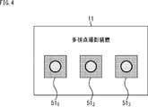
- FIG. 4 is a plan view showing a third configuration example of the multi-viewpoint photographing apparatus 11 of FIG.
- the multi-view imaging device 11 is composed of to three cameras 51 1 which are arranged at equal intervals in the horizontal direction 51 3.
- FIG. 5 is a plan view showing a fourth configuration example of the multi-viewpoint photographing apparatus 11 of FIG.
- the multi-viewpoint imaging device 11 similarly to FIG. 3, and is a stereo camera constituted by two cameras 51 1 and 51 2 arranged side by side in the horizontal direction.
- one or both of the two cameras 51 1 and 51 2 can be moved in the horizontal direction, and accordingly, the optical axis of the camera 51 1 baseline length is the distance between the optical axis of the camera 51 2 is made variable with.
- the camera 51 2 is adapted to be moved in the horizontal direction.
- FIG. 6 is a diagram for explaining the relationship between the disparity and the subject distance.
- the image processing unit 26 for example, using two viewpoints of the viewpoint images taken by the horizontally side by side disposed two cameras 51 1 and 51 2, and obtaining the disparity.
- two cameras 51 1 and 51 2 it is assumed that a camera of the same specifications.
- the horizontal resolution pixel two and the baseline length camera 51 1 and 51 2 B, and the horizontal angle a of the camera 51 1 and 51 2, view image photographed by the camera 51 1 and 51 2
- the relationship between the disparity D and the subject distance L is expressed by equation (1).
- the image processing unit 26 performs image processing for matching the viewpoint images of the two viewpoints, for example, using the viewpoint images of the two viewpoints, thereby generating a disparity with respect to at least one of the viewpoint images of the two viewpoints. Are determined for each pixel of the viewpoint image.
- the base length B is selected according to how to select two viewpoints used in the image processing of the image processing unit 26. To change the (range of) the disparity D determined by image processing.
- the base length B1 between the camera 51 1 and the camera 51 2 is 1/2 of.
- the disparity obtained by using the captured view image by the camera 51 1 captured view image and the camera 51 2 is photographed viewpoint image viewpoint image and the camera 51 3 taken by the camera 51 1 And one half of the disparity obtained using
- multi-view imaging apparatus 11 by changing the camera 51 i and 51 j of the pair taking a viewpoint image of two viewpoints for use in image processing, to change the base length B, It is possible to change (the range of) the disparity D required for image processing.
- the multi-view imaging apparatus 11 shown in FIG. 5 by moving the camera 51 2, it is possible to change the disparity D of change of the base length B, is determined by image processing.
- the disparity D As the subject distance L is smaller (closer), the disparity D has a larger value, and the (detection) resolution of the disparity D becomes higher.
- the larger the subject distance L the smaller the disparity D, and the resolution of the disparity D becomes lower.
- the maximum disparity affects the storage capacity of a memory used for image processing and the amount of calculation in image processing.
- each of the pixels of the base image is selected as the target pixel as one of the viewpoint images of the two viewpoints as a base image serving as a base, and the target pixel is centered.
- a region of a predetermined size centered on a position deviated from the position of the pixel of interest of the region R1 of the predetermined size and the viewpoint image of the other of the viewpoint images of the two viewpoints by the disparity candidate serving as the disparity candidate of the pixel of interest A match with the region R2 is taken.
- a disparity candidate having the best evaluation value of matching for example, a square sum of pixel values of pixels at the same position in each of the regions R1 and R2 is determined as the disparity of the pixel of interest.
- the evaluation value of matching is obtained, for example, by setting 0 as the minimum disparity, using the range from the minimum disparity to the maximum disparity as the search range of the disparity and using the value of the search range as the disparity candidate Be
- the maximum disparity is the maximum value of the disparity candidate and defines the search range of the disparity, and therefore affects the storage capacity of the memory used for image processing and the amount of operation in the image processing.
- the minimum disparity is fixed to 0, the minimum disparity can be set to any value less than the maximum disparity.
- the minimum disparity is set to an arbitrary value, the minimum disparity, together with the maximum disparity, defines the search range of the disparity, and thus affects the amount of calculation in image processing.
- the maximum disparity affects the storage capacity of the memory used for image processing and the amount of computation in image processing, it is desirable that the maximum disparity be small.
- the maximum disparity is small, the disparity determined by image processing
- the maximum value of parity is limited. That is, the minimum value of the subject distance obtained by the image processing is limited.
- the disparity can be accurately obtained for the object in image processing. An error may occur.
- the disparity as disparity information can be appropriately determined. That is, in the present technology, for example, reducing the storage capacity of a memory used for image processing, reducing the amount of calculation in image processing, and suppressing occurrence of an error in image processing for finding disparity It can be so.
- the subject distance detected by the distance detection unit 21 at the time of shooting of the subject is fed back (feed forward) to the image processing for obtaining the disparity after shooting of the subject.
- the storage capacity of a memory used for image processing and the amount of calculation in image processing can be reduced and errors can be suppressed.
- Figure 7 is a sectional view showing a configuration example of a pixel having the camera 51 i is.
- the distance detection unit 21 detects the subject distance up to the subject appearing in the viewpoint image when the multi-viewpoint photographing apparatus 11 captures the subject.
- an active sensor which is a distance sensor which emits light and receives a reflected light of the light to detect the distance emits light
- a detection method using a passive sensor that is a distance sensor that detects a distance without changing the distance.
- an active sensor for example, there is a TOF (Time Of Flight) sensor, and as a passive sensor, for example, an image sensor corresponding to image plane phase difference AF (Auto Focus) (hereinafter also referred to as image plane phase difference sensor) ).
- TOF Time Of Flight
- passive sensor for example, an image sensor corresponding to image plane phase difference AF (Auto Focus) (hereinafter also referred to as image plane phase difference sensor) ).
- any detection method using an active sensor as described above and a detection method using a passive sensor can be adopted.
- a detection method using a passive sensor is adopted as a detection method for detecting a subject distance at the time of shooting a subject.
- At least one camera 51 i (for example, a camera 51 i for capturing a viewpoint image to be a base image) configuring the multi-viewpoint imaging device 11 is configured using an image plane phase difference sensor Be done.
- FIG. 7 shows a configuration example of a pixel of the image plane phase difference sensor.
- the pixel includes a plurality of, for example, two PDs (Photo Diodes) 61A and 61B, a CF (Color Filter) 62, and a microlens 63.
- PDs Photo Diodes
- CF Color Filter
- the two PDs 61A and 61B are disposed side by side in the horizontal direction, and a CF 62 is formed on top of the two PDs 61A and 61B.
- the microlens 63 is disposed on the top of the CF 62.
- one microlens 63 is disposed for two PDs 61A and 61B.
- the focus lens is moved to the in-focus position by driving the focus lens so as to minimize the phase difference between the A layer signal and the B layer signal.
- the subject distance can be obtained from the phase difference between the A layer signal and the B layer signal, and the distance detection unit 21 obtains the A layer signal and the B layer obtained for each shooting of the subject by the multi-viewpoint photographing apparatus 11.
- the subject distance is detected according to phase difference information representing a phase difference between the signal and the signal.
- the image plane phase difference method using pixels in which one micro lens 63 is disposed for two PDs 61A and 61B is called a micro lens method.
- the addition value of the signals of the PDs 61A and 61B constituting a pixel is used as the pixel value of that pixel.
- a micro lens system is adopted as the image plane phase difference system here, other than the micro lens system, for example, a pixel is configured by one PD as the image plane phase difference system.
- a light blocking method for obtaining the A layer signal and the B layer signal from the pixel in which the left half of the PD is light-shielded and the pixel in which the right half is light-shielded can be adopted.
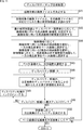
- FIG. 8 is a flowchart for explaining an example of the photographing process performed by the photographing system of FIG.
- step S11 the multi-viewpoint photographing apparatus 11 starts photographing of a subject (viewpoint images of a plurality of viewpoints) from a plurality of viewpoints, and stores the viewpoint images of a plurality of viewpoints obtained by the photographing
- step S12 the process proceeds to step S12.
- step S12 the multi-viewpoint imaging device 11, for the image plane the light receiving surface of the phase difference sensor as an image sensor (not shown) to the camera 51 i has to set a plurality of detection areas for detecting a subject distance, processing step Go to S13.
- the multi-viewpoint photographing apparatus 11 when a plurality of detection areas for detecting the subject distance are set for the light receiving surface of the image plane phase difference sensor, the multi-viewpoint photographing apparatus 11 outputs phase difference information obtained in each of the plurality of detection areas.
- the phase difference information of each of the plurality of detection areas output from the multi-viewpoint photographing apparatus 11 is supplied to the distance detection unit 21.
- step S13 the distance detection unit 21 detects, for each of the plurality of detection areas, the subject distance of the subject appearing in the detection area from the phase difference information from the multi-viewpoint photographing apparatus 11, and supplies the same to the minimum distance detection unit 22. Then, the process proceeds to step S14.
- step S14 the minimum distance detection unit 22 detects the minimum object distance among the object distances detected for each of the plurality of detection areas supplied from the distance detection unit 21, and supplies the minimum object distance to the storage unit 23. The process proceeds to step S15.
- step S15 the storage unit 23 waits for the shutter button of the operation unit 31 to be fully pressed, and then the image files of the viewpoint images of the plurality of viewpoints supplied from the multi-viewpoint imaging device 11 and the minimum distance detection unit 22. In association with the minimum subject distance supplied from
- steps S13 and S14 are repeated as necessary until the shutter button of the operation unit 31 is full-pressed.
- the processing in steps S13 and S14 is repeatedly performed until the shutter button of the operation unit 31 is full-pressed after the start of photographing by the multi-viewpoint photographing apparatus 11, or the shutter button of the operation unit 31 is half-pressed It can be repeated only for a while.
- the distance detection unit 21 can move the focusing plane to a plurality of positions by controlling the multi-viewpoint photographing apparatus 11, and can detect the subject distance with respect to the focusing plane at each position. In this case, the distance detection unit 21 can detect the minimum object distance from among the object distances detected for the focal plane at each position and each of the plurality of detection areas.
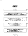
- FIG. 9 is a flowchart for explaining an example of disparity map generation processing as image processing performed by the imaging system of FIG.
- step S21 the reading unit 24 determines an image file to be processed from the image files stored in the storage unit 23, and the process proceeds to step S22.
- the read-out unit 24 is the oldest image file for which a disparity map is not generated, an image file specified by the user operating the operation unit 31, etc. Is determined as the file to be processed.
- step S22 the reading unit 24 reads, from the storage unit 23, the image file to be processed and the minimum subject distance associated with the image file (the viewpoint images of the plurality of viewpoints). Furthermore, the reading unit 24 supplies viewpoint images of a plurality of viewpoints of the image file to be processed to the image processing unit 26, and supplies the minimum subject distance associated with the image file to be processed to the setting unit 25. Then, the process proceeds from step S22 to step S23.
- step S23 the setting unit 25 sets the maximum disparity obtained by the image processing of the image processing unit 26 in accordance with the minimum subject distance from the reading unit 24, and performs control processing representing control information representing the maximum disparity. After supplying the unit 26, the process proceeds to step S24.
- the setting unit 25 sets the disparity (value or more) corresponding to the minimum subject distance to the maximum disparity.
- step S24 the image processing unit 26 selects viewpoint images of two viewpoints used for image processing from the viewpoint images of the plurality of viewpoints from the reading unit 24, and selects one of the viewpoint images of the two viewpoints. An image is selected as the base image, and the process proceeds to step S25.
- step S25 the image processing unit 26 selects one pixel not selected as the target pixel from the pixels of the base image as the target pixel, and the process proceeds to step S26.
- step S26 the image processing unit 26 sets the disparity candidate to, for example, 0 which is the default minimum disparity, and the process proceeds to step S27.
- step S27 the image processing unit 26 obtains an evaluation value indicating the probability that the disparity candidate is the disparity of the pixel of interest, and the process proceeds to step S28.
- the image processing unit 26 determines the disparity from the position of the pixel of interest of the region R1 of a predetermined size centered on the pixel of interest of the base image and the other viewpoint image of the viewpoint images of the two viewpoints used for image processing. For a region R2 of a predetermined size centered on the position shifted by the candidate, the sum of squares of pixel values of each pixel of the region R1 and the corresponding pixel (position) of the region R2 is calculated as the evaluation value of the disparity candidate .
- step S28 the image processing unit 26 determines whether the disparity candidate is equal to the maximum disparity represented by the control information from the setting unit 25.
- step S28 If it is determined in step S28 that the disparity candidate is not equal to the maximum disparity, the process proceeds to step S29, and the image processing unit 26 increments the disparity candidate by a predetermined step width. Then, the process returns from step S29 to 27 and the same process is repeated thereafter.
- step S28 If it is determined in step S28 that the disparity candidate is equal to the maximum disparity, that is, the range from 0 which is the default minimum disparity to the maximum disparity set according to the minimum object distance
- the process proceeds to step S30.
- step S30 the image processing unit 26 determines the disparity candidate with the best evaluation value as the disparity of the pixel of interest, and the process proceeds to step S31.
- step S31 the image processing unit 26 determines whether all pixels of the base image have been selected as the pixel of interest, and determines that all pixels of the base image have not yet been selected as the pixel of interest , Processing returns to step S25.
- step S31 When it is determined in step S31 that all the pixels of the base image have been selected as the pixel of interest, the image processing unit 26 sets an image having the pixel value of each pixel of the base image as the disparity map And the disparity map generation process ends.
- the maximum disparity is set according to the minimum subject distance, and from the default minimum disparity of 0 to the maximum disparity set according to the minimum subject distance.
- Disparity is determined using the range as a search range for disparity. Therefore, since the search range of the disparity is limited by the subject distance (minimum subject distance) of the closest subject shown in the viewpoint image to the range necessary to obtain the disparity for the viewpoint image, such limitation is not made. Compared to the case, it is possible to reduce the storage capacity of the memory used for image processing for obtaining the disparity and the amount of calculation in the image processing.
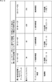
- FIG. 10 is a diagram showing an example of setting of the accuracy of disparity according to the minimum object distance.
- the setting unit 25 can set the accuracy of the disparity according to the minimum object distance.
- the disparity in the image processing unit 26, the disparity can be obtained while incrementing the disparity candidate by a predetermined step width in the search range of the disparity, but the accuracy of the disparity is determined by the predetermined step width.
- the disparity is represented by, for example, a bit string of 8 bits, it is possible to represent a disparity of 256 gradations from 0 to 255.
- the setting unit 25 can set the accuracy of the disparity according to the minimum subject distance.
- the setting unit 25 sets the maximum disparity to 30 and sets a predetermined step width as the disparity accuracy. , 1/8 pixels. In this case, 0 to 30 (0, 1/8, 2/8,...) With 1/8 pixel accuracy using, for example, 241 gradations out of 256 gradations expressed by a bit string of 8 bits. The disparity of can be expressed.
- the setting unit 25 sets the maximum disparity to 60 and sets a predetermined step width as the disparity accuracy.
- the disparity of can be expressed.
- the setting unit 25 sets the maximum disparity to 120 and sets a predetermined step width as the disparity accuracy.
- the setting unit 25 sets the maximum disparity to 255 and sets a predetermined step width as the disparity accuracy. , Set to one pixel.
- a disparity of 0 to 255 (0, 1, 2,8) Can be represented with one-pixel accuracy using 256 gradations represented by a bit string of 8 bits.
- the setting unit 25 sets a predetermined step width as the accuracy of disparity according to the minimum object distance, and supplies control information representing the predetermined step width to the image processing unit 26. Can. Then, the image processing unit 26 increments the disparity candidate in step S29 (FIG. 9) with the step width represented by the control information from the setting unit 25 so that the disparity corresponding to the predetermined step width is generated. Parity can be determined.
- FIG. 11 is a flowchart for explaining another example of disparity map generation processing as image processing performed by the imaging system of FIG.
- the maximum value of the disparity (hereinafter, also referred to as a disparity limit value) that can be obtained by the image processing unit 26 may be determined.
- the disparity corresponding to the minimum subject distance exceeds the disparity limit value, in the image processing for obtaining the disparity, the disparity corresponding to the minimum subject distance can not be accurately determined, and an error may occur. is there.
- the disparity D is proportional to the base length B and the horizontal resolution H of the viewpoint image, and the base length B and the viewpoint image It becomes smaller as the horizontal resolution H becomes smaller.
- the disparity corresponding to the minimum object distance is controlled so as not to exceed the disparity limit value. It is possible to suppress the occurrence of an error in image processing for obtaining the disparity.
- steps S21 and S22 of FIG. 9 are performed in steps S41 and S42.
- step S43 the setting unit 25 sets two viewpoints of two viewpoints to be used in the image processing of the image processing unit 26 according to the minimum subject distance from the reading unit 24 and the disparity limit value.
- the control information representing the viewpoint image is supplied to the image processing unit 26, and the process proceeds to step S44.
- the setting unit 25 performs the image processing unit 26 on the viewpoint image captured by each of the two cameras 51 i and 51 j of the base length B whose disparity corresponding to the minimum subject distance is equal to or less than the disparity limit value.
- the viewpoint images of two viewpoints used for the image processing of are set.
- the base length B is set so that the disparity corresponding to the minimum object distance becomes equal to or less than the disparity limit value. Adjusted (changed).
- step S44 the image processing unit 26 selects, from among the viewpoint images of the plurality of viewpoints from the reading unit 24, two viewpoints images represented by the control information from the setting unit 25 in the image processing of two viewpoints And select one of the viewpoint images of the two viewpoints as a base image.
- step S43 the setting unit 25 sets the horizontal resolution H of the viewpoint image of the two viewpoints used for the image processing of the image processing unit 26 according to the minimum subject distance from the reading unit 24 and the disparity limit value.
- the control information representing the horizontal resolution H is supplied to the image processing unit 26, and the process proceeds to step S44.
- the setting unit 25 sets the horizontal resolution H in which the disparity corresponding to the minimum object distance is equal to or less than the disparity limit value.
- step S44 the image processing unit 26 selects viewpoint images of two viewpoints to be used for image processing from viewpoint images of a plurality of viewpoints from the reading unit 24, and sets horizontal resolutions of the viewpoint images of the two viewpoints. It adjusts so that it may become horizontal resolution H (or less) which the control information from the part 25 represents (thinning). Then, the image processing unit 26 selects one of the viewpoint images of the two viewpoints after adjustment of the horizontal resolution as a base image.
- step S44 proceeds from step S44 to step S45, and in steps S45 to S51, processes similar to steps S25 to S31 in FIG. 9 are respectively performed.
- the smaller one of the disparity (disparity after adjustment of the base length B and the horizontal resolution H) and the disparity limit value corresponding to the minimum object distance is set as the maximum disparity.
- the minimum distance detection unit 22 detects the minimum object distance among the object distances of various objects supplied from the distance detection unit 21 and detects the maximum object distance (hereinafter, maximum object distance). be able to.
- the setting unit 25 sets the minimum disparity, which is the minimum value of disparity as disparity information obtained by the image processing of the image processing unit 26, according to the maximum subject distance, and Control information representing the minimum disparity can be supplied to the image processing unit 26.
- the setting unit 25 can supply control information representing the minimum disparity and the maximum disparity to the image processing unit 26.
- the image processing unit 26 may obtain the disparity with respect to the viewpoint image with the disparity equal to or more than the minimum disparity as the search range. it can.
- control information indicating the minimum disparity and the maximum disparity is supplied from the setting unit 25 to the image processing unit 26, the image processing unit 26 searches for the disparity between the minimum disparity and the minimum disparity. It is possible to determine the disparity with respect to the viewpoint image as
- control information representing the minimum disparity is supplied from the setting unit 25 to the image processing unit 26, even when control information representing the minimum disparity and the maximum disparity is supplied.
- the search range when finding the disparity is limited. As a result, it is possible to speed up the image processing for obtaining the disparity and to reduce the storage capacity of the memory used for the image processing for obtaining the disparity.
- FIG. 12 is a block diagram showing a configuration example of a second embodiment of the imaging system to which the present technology is applied.
- the imaging system of FIG. 12 includes a multi-viewpoint imaging device 11, a UI device 13, and an image processing device 50.
- the imaging system of FIG. 12 is common to the case of FIG. 1 in that the multi-viewpoint imaging device 11 and the UI device 13 are included.
- the imaging system of FIG. 12 is different from the case of FIG. 1 in that an image processing apparatus 50 is provided instead of the image processing apparatus 12.
- the image processing apparatus 50 includes a distance detection unit 21, a minimum distance detection unit 22, a storage unit 23, an image processing unit 26, a setting unit 71, and a change request unit 72.
- the image processing apparatus 50 is common to the image processing apparatus 12 of FIG. 1 in that the distance detection unit 21 to the storage unit 23 and the image processing unit 26 are included.
- the image processing apparatus 50 is different from the case of FIG. 1 in that the reading unit 24 and the setting unit 25 are not provided, and the setting unit 71 and the change request unit 72 are newly provided.
- the setting unit 71 sets disparity information as a disparity threshold which is a threshold of disparity information according to disparity information obtained by image processing of the image processing unit 26, that is, for example, a disparity limit value which can be determined by the image processing unit 26. Are set and supplied to the change request unit 72.
- the setting unit 71 sets the disparity threshold value or a value equal to or less than the disparity threshold value as the disparity threshold.
- the disparity threshold is the maximum disparity obtained by the image processing of the image processing unit 26.
- the disparity threshold to be the maximum disparity is set in consideration of the storage capacity and operation amount of the memory and the search range of the disparity (range of the disparity which can be obtained by image processing). can do.
- the image processing unit 26 sets, for example, the minimum disparity to 0 and the maximum disparity as a disparity threshold, and the range from the minimum disparity to the maximum disparity is a disparity
- the image processing for finding the disparity is performed as a search range of
- the setting unit 71 can set the disparity threshold in accordance with, for example, the operation of the operation unit 31 by the user, in addition to setting the disparity threshold in accordance with the disparity limit value.
- the change request unit 72 is supplied with the disparity threshold from the setting unit 71, and is also supplied with the minimum subject distance from the minimum distance detection unit 22.
- the change request unit 72 controls the storage unit 23 and causes the storage unit 23 to store viewpoint images of a plurality of viewpoints captured by the multi-viewpoint imaging device 11.
- the change request unit 72 performs a change request process for requesting a change of the photographing state according to the disparity threshold from the setting unit 71 and the minimum subject distance from the minimum distance detection unit 22.
- the image processing unit 26 sets the minimum disparity to 0 and specifies the maximum disparity as the disparity threshold, and searches for a range from the minimum disparity to the maximum disparity in the disparity Since image processing for obtaining the disparity is performed as a range, if the disparity corresponding to the minimum object distance is larger than the disparity threshold, the correct disparity can not be obtained and an error occurs. There is.
- the change request unit 72 performs change request processing, and the disparity corresponding to the minimum subject distance is equal to or less than the disparity threshold. Change the shooting condition so that That is, the user (of the imaging system) is urged to perform imaging while changing the imaging state.
- the change request unit 72 restricts (full operation of) the shutter button of the operation unit 31 operated by the user. While notifying that an error occurs, a request for changing the imaging state is made.
- the change request unit 72 causes the display unit 32 to perform predetermined display, for example, lighting of a warning LED in the change request process, thereby causing the user to perform image processing in the current shooting state. While notifying that an error occurs, a request for changing the imaging state is made.
- the change request unit 72 performs the above change request processing to urge the user to change the shooting state.
- the change request unit 72 ends the change request process. Further, the change request unit 72 causes the storage unit 23 to store viewpoint images of a plurality of viewpoints captured by the multi-viewpoint imaging device 11 in response to full pressing of the shutter button of the operation unit 31.
- the disparity corresponding to the minimum object distance can be made equal to or less than the disparity threshold by changing the base length B of the viewpoint image of the two viewpoints used for image processing for obtaining the disparity.
- the baseline length B of the two viewpoints of the viewpoint image used for the image processing for obtaining the disparity can be changed by selecting the two cameras 51 i.
- the camera 51 i of the multi-view imaging apparatus 11 can be performed by moving.
- the change request unit 72 performs the change request process according to the minimum subject distance among the subject distances of the subjects shown in the viewpoint images of the plurality of viewpoints photographed by the multi-viewpoint photographing apparatus 11 as described above. It can be said that the request unit 72 performs the change process according to the subject distance.
- the imaging system in FIG. 12 can be configured without the image processing unit 26. Further, the image processing unit 26 can be provided on the cloud, not on the imaging system.
- the change request process is performed when the disparity corresponding to the minimum subject distance is greater than the disparity threshold, but the change request process corresponds to the minimum subject distance. Performed when the disparity corresponding to the maximum subject distance is less than another predetermined disparity threshold (value less than the disparity threshold) other than when the disparity is greater than the disparity threshold be able to.
- the minimum disparity is defined as another disparity threshold
- the maximum disparity is defined as a disparity threshold
- the range from the minimum disparity to the maximum disparity is searched for disparity
- FIG. 13 is a flowchart for explaining an example of the photographing process performed by the photographing system of FIG.
- the distance detection at the time of shooting of the subject is based on (a disparity limit value defining the range of disparity that can be obtained by image processing of the image processing unit 26 performed after shooting of the subject (viewpoint image).
- a disparity limit value defining the range of disparity that can be obtained by image processing of the image processing unit 26 performed after shooting of the subject (viewpoint image).
- step S81 the setting unit 71 sets a disparity threshold according to the disparity limit value, supplies the disparity threshold to the change request unit 72, and the process proceeds to step S82.
- step S82 the multi-viewpoint photographing apparatus 11 starts photographing of subjects (viewpoint images of a plurality of viewpoints) from a plurality of viewpoints, and supplies viewpoint images of a plurality of viewpoints obtained by the photographing to the storage unit 23. Then, the process proceeds to step S83.
- step S83 the multi-view imaging apparatus 11, the image plane the light receiving surface of the phase difference sensor as an image sensor (not shown) to the camera 51 i has to set a plurality of detection areas for detecting a subject distance, processing step Go to S84.
- the multi-viewpoint photographing apparatus 11 when a plurality of detection areas for detecting the subject distance are set for the light receiving surface of the image plane phase difference sensor, the multi-viewpoint photographing apparatus 11 outputs phase difference information obtained in each of the plurality of detection areas.
- the phase difference information of each of the plurality of detection areas output from the multi-viewpoint photographing apparatus 11 is supplied to the distance detection unit 21.
- step S84 the distance detection unit 21 detects, for each of the plurality of detection areas, the subject distance of the subject appearing in the detection area from the phase difference information from the multi-viewpoint photographing apparatus 11, and supplies it to the minimum distance detection unit 22. Then, the process proceeds to step S85.
- step S85 the minimum distance detection unit 22 detects the minimum object distance among the object distances detected for each of the plurality of detection areas supplied from the distance detection unit 21, and supplies the minimum object distance to the change request unit 72. Then, the process proceeds to step S86.
- step S86 the change request unit 72 determines whether the disparity corresponding to the minimum subject distance from the minimum distance detection unit 22 is less than or equal to the disparity threshold from the setting unit 71.
- step S86 If it is determined in step S86 that the disparity corresponding to the minimum subject distance is not equal to or less than the disparity threshold, the process proceeds to step S87, the change request unit 72 performs a change request process, and the user is notified of the photographing state Prompt change of Then, the process returns from step S87 to step S84, and the same process is repeated thereafter.
- step S86 If it is determined in step S86 that the disparity corresponding to the minimum object distance is equal to or less than the disparity threshold, the change request unit 72 performs the change request process if the change request process is being performed. The process ends, and the process proceeds to step S88.
- step S88 the change request unit 72 waits for the shutter button of the operation unit 31 to be fully pressed, and (the image file of) the viewpoint images of the plurality of viewpoints supplied from the multi-viewpoint photographing device 11 to the storage unit 23. Are stored in the storage unit 23.
- the viewpoint images of the plurality of viewpoints stored in the storage unit 23 are appropriately used in image processing for obtaining the disparity in the image processing unit 26.
- steps S84 to S87 are repeated as necessary until the shutter button of the operation unit 31 is full-pressed.
- the processing in steps S84 to S87 is repeatedly performed until the shutter button of the operation unit 31 is full-pressed, or the shutter button of the operation unit 31 is half-pressed after shooting of the multi-viewpoint photographing apparatus 11 starts. It can be repeated only for a while.
- the imaging system of FIG. 1 can include the functions of the imaging system of FIG. 12.
- the maximum disparity is known because the disparity threshold is the maximum disparity. Therefore, the setting unit 25 sets the disparity corresponding to the maximum subject distance to the minimum disparity according to the maximum subject distance among the subject distances, and the image processing unit 26 sets the maximum known from the minimum disparity.
- the range up to the disparity can be used as a search range for the disparity to determine the disparity.
- FIG. 14 is a perspective view showing a configuration example of a camera system using the photographing system of FIG. 1 and FIG.
- the camera system is composed of a camera body 110 and a multi-lens interchangeable lens 120.
- the camera body 110 is configured such that the multi-lens interchangeable lens 120 can be attached and detached. That is, the camera body 110 has a camera mount 111, and (the lens mount 122 of) the multi-lens interchangeable lens 120 is attached to the camera mount 111, whereby the multi-lens interchangeable lens 120 is mounted on the camera body 110. It is attached. A general interchangeable lens other than the multi-lens interchangeable lens 120 can be attached to and detached from the camera body 110.
- the camera body 110 incorporates an image sensor 151.
- the image sensor 151 is, for example, a complementary metal oxide semiconductor (CMOS) image sensor, and receives light beams collected by a multi-lens interchangeable lens 120 mounted on (the camera mount 111 of) the camera body 110. The image is taken by performing photoelectric conversion.
- CMOS complementary metal oxide semiconductor
- the multi-lens interchangeable lens 120 has a lens barrel 121 and a lens mount 122.
- the lens barrel 121 so as not to overlap in the optical axis direction (as viewed), a plurality of lenses 4 ommatidium lens 131 1, 131 2, 131 3 and 131 4 are arranged.
- the barrel 121, 4 ommatidium lens 131 1 to 131 4 perpendicular to the optical axis (parallel to the light receiving surface of the image sensor 151 (the imaging plane)) vertex diamond on a two-dimensional plane It is arranged at the position where
- Ommatidium lens 131 1 to 131 4 when the multiview interchangeable lens 120 is attached to the camera body 110, to focus the light beam from the object to the image sensor 151 of the camera body 110.
- the camera body 110 is a so-called single-plate camera having one image sensor 151, but as the camera body 110, a plurality of image sensors, that is, RGB (Red, Green, Blue, for example) )
- RGB Red, Green, Blue, for example
- a so-called three-plate camera having three image sensors for each can be employed.
- the lens mount 122 is attached to the camera mount 111 of the camera body 110 when the multi-lens interchangeable lens 120 is attached to the camera body 110.
- the multiview interchangeable lens 120 although four ommatidium lens 131 1 to 131 4 are provided, the number of ommatidia lens provided in the multiview interchangeable lens 120 is limited to four It is possible to adopt two, three, five or more arbitrary plural numbers.
- the plurality of individual lenses provided in the multi-lens interchangeable lens 120 can be arranged at any position on a two-dimensional plane in addition to being arranged at the position of the apex of the rhombus.
- a plurality of individual lenses provided in the multi-lens interchangeable lens 120 a plurality of lenses having the same focal length, f-number, and other specifications may be employed, or a plurality of lenses having different specifications may be employed. You can also.
- the four ommatidium lens 131 1 to 131 4 respectively as a plurality, when multiview interchangeable lens 120 is attached to the camera body 110, the optical axis and the light-receiving surface of the image sensor 151 It is arranged to be orthogonal.
- the light sensor surface of the image sensor 151 receives the light beams collected by the four single lenses 1311 to 1314. An image corresponding to the image to be formed is taken.
- 1 the image captured by the number of the image sensor 151, formed by light rays focused by four ommatidium lens 131 1 to 131 4 4 ommatidium image for each (single-eye lens 131 1 to 131 4 respectively Image corresponding to the image to be
- Ommatidium image against the ommatidium lens 131 i number a ophthalmic lens 131 i image located a viewpoint of, therefore, four ommatidium image with respect to 131 4 each ommatidium lens 131 1 is different viewpoints viewpoints It is an image.
- the image processing apparatus 12 and 1, the image processing apparatus 50 of FIG. 12, the treatment by setting a four ommatidium image with respect to 131 4 different is ommatidium lens 131 1 a viewpoint of the viewpoint image as described above It can be carried out.
- the series of processes of the image processing apparatus 12 or 50 described above can be performed by hardware or software.
- a program constituting the software is installed in a general-purpose computer or the like.
- FIG. 15 is a block diagram showing a configuration example of an embodiment of a computer in which a program for executing the series of processes described above is installed.
- the program can be recorded in advance in a hard disk 205 or a ROM 203 as a recording medium built in the computer.
- the program can be stored (recorded) in the removable recording medium 211.
- Such removable recording medium 211 can be provided as so-called package software.
- examples of the removable recording medium 211 include a flexible disk, a compact disc read only memory (CD-ROM), a magneto optical disc (MO), a digital versatile disc (DVD), a magnetic disc, a semiconductor memory, and the like.
- the program may be installed on the computer from the removable recording medium 211 as described above, or may be downloaded to the computer via a communication network or a broadcast network and installed on the built-in hard disk 205. That is, for example, the program is wirelessly transferred from the download site to the computer via an artificial satellite for digital satellite broadcasting, or transferred to the computer via a network such as a LAN (Local Area Network) or the Internet. be able to.
- a network such as a LAN (Local Area Network) or the Internet.
- the computer incorporates a CPU (Central Processing Unit) 202, and an input / output interface 210 is connected to the CPU 202 via a bus 201.
- CPU Central Processing Unit
- the CPU 202 executes a program stored in a ROM (Read Only Memory) 203 accordingly. .
- the CPU 202 loads a program stored in the hard disk 205 into a random access memory (RAM) 204 and executes the program.
- RAM random access memory
- the CPU 202 performs the processing according to the above-described flowchart or the processing performed by the configuration of the above-described block diagram. Then, the CPU 202 outputs the processing result from the output unit 206 or transmits it from the communication unit 208 through the input / output interface 210, for example, and records the processing result on the hard disk 205, as necessary.
- the input unit 207 is configured of a keyboard, a mouse, a microphone, and the like. Further, the output unit 206 is configured of an LCD (Liquid Crystal Display), a speaker, and the like.
- LCD Liquid Crystal Display
- the processing performed by the computer according to the program does not necessarily have to be performed chronologically in the order described as the flowchart. That is, the processing performed by the computer according to the program includes processing executed in parallel or separately (for example, parallel processing or processing by an object).
- the program may be processed by one computer (processor) or may be distributed and processed by a plurality of computers. Furthermore, the program may be transferred to a remote computer for execution.
- the system means a set of a plurality of components (apparatus, modules (parts), etc.), and it does not matter whether all the components are in the same housing or not. Therefore, a plurality of devices housed in separate housings and connected via a network, and one device housing a plurality of modules in one housing are all systems. .
- the present technology can have a cloud computing configuration in which one function is shared and processed by a plurality of devices via a network.
- each step described in the above-described flowchart can be executed by one device or in a shared manner by a plurality of devices.
- the plurality of processes included in one step can be executed by being shared by a plurality of devices in addition to being executed by one device.
- the present technology can be configured as follows.
- An image for which parallax information with respect to the viewpoint image is obtained by performing image processing using the viewpoint image according to the subject distance to the subject appearing in the viewpoint images photographed from a plurality of viewpoints detected at the time of photographing the object An image processing apparatus comprising a processing unit.
- the image processing unit obtains image parallax information with respect to the viewpoint image by performing image processing using the viewpoint image according to the minimum minimum object distance among the object distances.
- apparatus ⁇ 3>
- the image processing apparatus further includes a setting unit that sets a maximum value or a minimum value of disparity information obtained by the image processing according to the minimum subject distance.
- the image processing unit performs image processing using the viewpoint image according to the maximum value or the minimum value of the disparity information to obtain disparity information less than the maximum value or disparity information greater than the minimum value.
- the apparatus further comprises a setting unit configured to set a viewpoint image used for the image processing according to the minimum subject distance,
- the image processing apparatus further comprises a setting unit configured to set the resolution of the viewpoint image used for the image processing according to the minimum subject distance, The image processing apparatus according to ⁇ 2>, wherein the image processing unit obtains parallax information with respect to the viewpoint image by performing the image processing using the viewpoint image of the resolution set according to the minimum subject distance.
- the image processing apparatus further includes a setting unit configured to set the accuracy of parallax information obtained by the image processing in accordance with the minimum subject distance.
- ⁇ 7> The image processing apparatus according to any one of ⁇ 1> to ⁇ 6>, further including a distance detection unit that detects the subject distance.
- ⁇ 8> The image processing apparatus according to ⁇ 7>, wherein the distance detection unit detects the subject distance by an image plane phase difference method.
- ⁇ 9> Determining parallax information with respect to the viewpoint image by performing image processing using the viewpoint image according to the subject distance to the subject appearing in the viewpoint images captured from a plurality of viewpoints detected at the time of imaging of the subject Image processing method including.
- An image for which parallax information with respect to the viewpoint image is obtained by performing image processing using the viewpoint image according to the subject distance to the subject appearing in the viewpoint images photographed from a plurality of viewpoints detected at the time of photographing the object A program to make a computer function as a processing unit.
- An image processing apparatus comprising: a change request unit configured to request a change of a photographing state of the subject according to a subject distance to a subject appearing in a viewpoint image photographed from a plurality of viewpoints detected at the time of photographing of a subject.
- the image processing apparatus further includes an image processing unit for obtaining parallax information with respect to the viewpoint image by performing image processing using the viewpoint image.
- the change request unit requests a change of the photographing state of the subject according to the parallax information obtained by the image processing and the minimum minimum subject distance among the subject distances.
- Processing unit. further includes a setting unit configured to set a parallax threshold which is a threshold of the parallax information according to the parallax information obtained by the image processing.
- the image processing apparatus according to ⁇ 12> wherein the change request unit requests the change of the imaging state according to the parallax threshold and the minimum subject distance.
- ⁇ 15> The image processing apparatus according to any one of ⁇ 11> to ⁇ 13>, wherein the change request unit requests the user to change the imaging state by performing a predetermined display.
- ⁇ 16> The image processing apparatus according to any one of ⁇ 11> to ⁇ 15>, further including a distance detection unit that detects the subject distance.
- ⁇ 17> The image processing apparatus according to ⁇ 16>, wherein the distance detection unit detects the subject distance by an image plane phase difference method.
- An image processing method comprising: requesting a change in a photographing state of the subject according to a subject distance to a subject appearing in a viewpoint image photographed from a plurality of viewpoints detected at the time of photographing a subject.
- 11 multi-viewpoint photographing apparatus 12 image processing apparatus, 13 UI apparatus, 21 distance detection unit, 22 minimum distance detection unit, 23 storage unit, 24 readout unit, 25 setting unit, 26 image processing unit, 31 operation unit, 32 display unit , 51 i camera (unit), 61A, 61B PD, 62 CF, 63 micro lens, 71 setting unit, 72 change request unit, 110 camera main body, 111 camera mount, 120 multi-lens interchangeable lens, 121 lens barrel, 122 lens mount , 123 lens hood, 131 i single lens, 151 image sensor, 201 bus, 202 CPU, 203 ROM, 204 RAM, 205 hard disk, 206 output unit, 207 input unit, 208 communication unit, 209 drive, 210 I / O interface, 211 Removable recording medium
Landscapes
- Engineering & Computer Science (AREA)
- Physics & Mathematics (AREA)
- General Physics & Mathematics (AREA)
- Theoretical Computer Science (AREA)
- Computer Vision & Pattern Recognition (AREA)
- Geometry (AREA)
- Optics & Photonics (AREA)
- Studio Devices (AREA)
- Image Analysis (AREA)
- Image Processing (AREA)
- Testing, Inspecting, Measuring Of Stereoscopic Televisions And Televisions (AREA)
Abstract
本技術は、視差情報を適切に求めることができるようにする画像処理装置、画像処理方法、及び、プログラムに関する。 画像処理部は、被写体の撮影時に検出された、複数の視点から撮影された視点画像に映る被写体までの被写体距離に応じて、視点画像を用いた画像処理を行うことにより、視点画像に対する視差情報を求める。本技術は、例えば、複数の視点の視点画像を用いた画像処理により、視点画像に対する視差情報を求める場合等に適用することができる。
Description
本技術は、画像処理装置、画像処理方法、及び、プログラムに関し、特に、例えば、複数の視点の視点画像から、視差に関する視差情報を適切に求めることができるようにする画像処理装置、画像処理方法、及び、プログラムに関する。
例えば、位相差方式により、被写体までの被写体距離を算出するとともに、その被写体距離の確からしさを表す信頼度を算出し、被写体距離と信頼度とに基づいて、被写体距離の範囲を算出する技術が提案されている(例えば、特許文献1を参照)。
ところで、複数の視点の視点画像を用いた画像処理を行うことにより、視点画像に対して、その視点画像に映る被写体の視差に関する視差情報を求める場合に、画像処理を適切に行うことができず、視差情報を適切に求めることができないことがある。
例えば、視点画像に、視差が大きい被写体が映っている場合、すなわち、距離が近い被写体が映っている場合、視差情報を適切に求めることができないことがある。
本技術は、このような状況に鑑みてなされたものであり、複数の視点の視点画像から、視差情報を適切に求めることができるようにするものである。
本技術の第1の画像処理装置又はプログラムは、被写体の撮影時に検出された、複数の視点から撮影された視点画像に映る被写体までの被写体距離に応じて、前記視点画像を用いた画像処理を行うことにより、前記視点画像に対する視差情報を求める画像処理部を備える画像処理装置、又は、そのような画像処理装置としてコンピュータを機能させるためのプログラムである。
本技術の第1の画像処理方法は、被写体の撮影時に検出された、複数の視点から撮影された視点画像に映る被写体までの被写体距離に応じて、前記視点画像を用いた画像処理を行うことにより、前記視点画像に対する視差情報を求めることを含む画像処理方法である。
本技術の第1の画像処理装置、画像処理方法、及び、プログラムにおいては、被写体の撮影時に検出された、複数の視点から撮影された視点画像に映る被写体までの被写体距離に応じて、前記視点画像を用いた画像処理を行うことにより、前記視点画像に対する視差情報が求められる。
本技術の第2の画像処理装置又はプログラムは、被写体の撮影時に検出された、複数の視点から撮影された視点画像に映る被写体までの被写体距離に応じて、前記被写体の撮影状態の変更を要求する変更要求部を備える画像処理装置、又は、そのような画像処理装置としてコンピュータを機能させるためのプログラムである。
本技術の第2の画像処理方法は、被写体の撮影時に検出された、複数の視点から撮影された視点画像に映る被写体までの被写体距離に応じて、前記被写体の撮影状態の変更を要求することとを含む画像処理方法である。
本技術の第2の画像処理装置、画像処理方法、及び、プログラムにおいては、被写体の撮影時に検出された、複数の視点から撮影された視点画像に映る被写体までの被写体距離に応じて、前記被写体の撮影状態の変更が要求される。
なお、第1の画像処理装置や第2の画像処理装置は、独立した装置であっても良いし、1つの装置を構成している内部ブロックであっても良い。
また、プログラムは、伝送媒体を介して伝送することにより、又は、記録媒体に記録して、提供することができる。
本技術によれば、視差情報を適切に求めることができる。
なお、ここに記載された効果は必ずしも限定されるものではなく、本開示中に記載されたいずれかの効果であってもよい。
<本技術を適用した撮影システムの第1実施の形態>
図1は、本技術を適用した撮影システムの第1実施の形態の構成例を示すブロック図である。
図1において、撮影システムは、多視点撮影装置11、画像処理装置12、及び、UI(User Interface)装置13を有する。
多視点撮影装置11は、複数の視点から被写体を撮影し、これにより、複数の視点の視点画像を得て、画像処理装置12(の記憶部23)に供給する。
なお、多視点撮影装置11は、例えば、像面位相差方式によるAF(Auto Focus)の機能を有し、その像面位相差方式によるAFで得られる後述する位相差情報を、画像処理装置12(の距離検出部21)に供給する。
画像処理装置12は、距離検出部21、最小距離検出部22、記憶部23、読み出し部24、設定部25、及び、画像処理部26を有する。
距離検出部21は、多視点撮影装置11による被写体の撮影時に、多視点撮影装置11で撮影された視点画像に映る被写体までの被写体距離を検出し、最小距離検出部22に供給する。例えば、距離検出部21は、多視点撮影装置11から供給される位相差情報に応じて、多視点撮影装置11で撮影された視点画像に映る被写体までの被写体距離を検出し、最小距離検出部22に供給する。
最小距離検出部22は、距離検出部21から供給される、様々な被写体の被写体距離のうちの最小の被写体距離(以下、最小被写体距離ともいう)を検出し、記憶部23に供給する。なお、最小距離検出部22では、最小被写体距離の他、最大の被写体距離を検出することができる。
記憶部23は、多視点撮影装置11から供給される複数の視点の視点画像と、その視点画像に映る被写体の被写体距離のうちの、最小距離検出部22から供給される最小被写体距離とを対応付けて記憶する。
複数の視点の視点画像と最小被写体距離とを対応付ける方法としては、例えば、複数の視点の視点画像のファイルと最小被写体距離のファイルとを、ファイル名によって関連付ける方法を採用することができる。また、複数の視点の視点画像と最小被写体距離とを対応付ける方法としては、例えば、複数の視点の視点画像のファイルのヘッダ情報に、最小被写体距離を含める方法を採用することができる。
読み出し部24は、記憶部23に記憶された複数の視点の視点画像と、それらの複数の視点の視点画像に対応付けられた最小被写体距離とを読み出し、最小被写体距離を、設定部25に供給するとともに、複数の視点の視点画像を、画像処理部26に供給する。
設定部25は、読み出し部24から供給される最小被写体距離(や最大の被写体距離)に応じて、画像処理部26の画像処理を制御する制御情報を設定し、画像処理部26に供給することで、画像処理部26の画像処理を制御する。
例えば、設定部25は、最小被写体距離に応じて、画像処理部26の画像処理により求められる視差情報の最大値又は最小値を設定し、その視差情報の最大値又は最小値を表す制御情報を、画像処理部26に供給する。
また、設定部25は、最小被写体距離に応じて、画像処理部26の画像処理に用いる視点画像を設定し、その視点画像を表す制御情報を、画像処理部26に供給する。
さらに、設定部25は、最小被写体距離に応じて、画像処理部26の画像処理に用いる視点画像の解像度を設定し、その視点画像の解像度を表す制御情報を、画像処理部26に供給する。
また、設定部25は、最小被写体距離に応じて、画像処理部26の画像処理により求められる視差情報の精度を設定し、その視差情報の精度を表す制御情報を、画像処理部26に供給する。
なお、設定部25では、最小被写体距離に応じて、画像処理により求められる視差情報の最大値又は最小値、画像処理に用いる視点画像、画像処理に用いる視点画像の解像度、及び、画像処理により求められる視差情報の精度のうちの2以上を設定し、制御情報として、画像処理部26に供給することができる。
画像処理部26は、多視点撮影装置11による被写体の撮影後に、読み出し部24から供給される複数の視点の視点画像(のうちの2視点以上の視点画像)を用いた画像処理を行うことにより、(1視点以上の)視点画像に対して、その視点画像に映る被写体の視差に関する視差情報を求める(生成する)。
画像処理部26は、設定部25からの制御情報に従って、視差情報を求める画像処理を行う。
すなわち、設定部25からの制御情報が、画像処理により求められる視差情報の最大値又は最小値を表す場合には、画像処理部26は、制御情報が表す視差情報の最大値又は最小値に応じて、視点画像を用いた画像処理を行うことにより、その最大値以下の視差情報又は最小値以上の視差情報を求める。
また、設定部25からの制御情報が、画像処理に用いる視点画像を表す場合には、画像処理部26は、制御情報が表す視点画像を用いて画像処理を行うことにより、視差情報を求める。
さらに、設定部25からの制御情報が、画像処理に用いる視点画像の解像度を表す場合には、画像処理部26は、制御情報が表す解像度の視点画像を用いて画像処理を行うことにより、視差情報を求める。
また、設定部25からの制御情報が、画像処理により求められる視差情報の精度を表す場合には、画像処理部26は、制御情報が表す精度で、視差情報を求める。
以上のように、画像処理部26は、距離検出部21で検出される被写体距離のうちの、例えば、最小被写体距離に応じて設定される制御情報に従って、視差情報を求めるので、画像処理部26は、被写体距離に応じて、画像処理を行うことにより、視差情報を求める、ということができる。
なお、画像処理部26は、視差情報を求めた後、複数の視点の視点画像及び視差情報を用いて、複数の視点の視点画像から、フォーカスを変更して撮影を行った画像を再構成するリフォーカスその他の、複数の視点の視点画像及び視差情報を用いた画像処理を、必要に応じて行うことができる。
ここで、視差情報としては、視差を画素数で表したディスパリティ(disparity)や、視差に対応する奥行き方向の距離等の視差に換算することができる任意の情報を採用することができる。本実施の形態では、視差情報として、例えば、ディスパリティを採用することとし、画像処理部26では、画像処理により、ディスパリティが求められ、そのディスパリティが登録されたディスパリティマップが生成されることとする。
画像処理によりディスパリティが視差情報として求められる場合、設定部25が、最小被写体距離に応じて、画像処理部26の画像処理により求められる視差情報の最大値又は最小値を設定するときには、設定部25では、例えば、視差情報としてのディスパリティの最大値である最大ディスパリティ又は最小値である最小ディスパリティを設定することができる。最大ディスパリティは、画像処理部26が画像処理によりディスパリティを視差情報として求める場合の、そのディスパリティの最大値(最も近い被写体のディスパリティ)である。最小ディスパリティの最小値は、0である。
また、画像処理により距離が視差情報として求められる場合、設定部25が、最小被写体距離に応じて、画像処理部26の画像処理により求められる視差情報の最大値又は最小値を設定するときには、設定部25では、例えば、視差情報としての距離の最小値である最小距離又は最大値である最大距離を設定することができる。
以下では、説明を簡単にするため、視差情報として、ディスパリティを採用する場合について説明し、距離を採用する場合については、説明を省略する。なお、視差情報として、距離を採用する場合は、ディスパリティを採用する場合に対して、値の大小関係が逆になる。
UI装置13は、ユーザとのインターフェースとして機能する。UI装置は、例えば、操作部31や表示部32を有する。
操作部31は、図示せぬシャッタボタン等の各種のボタンやレバー等を有し、ユーザによって操作され、その操作に対応する操作信号を、必要なブロックに供給する。
表示部32は、タッチパネル等で構成され、多視点撮影装置11で撮影された(視点)画像を、いわゆるスルー画として表示する。また、表示部32は、撮影システムの設定のためのメニュー等の各種の表示を行う。
なお、図1の撮影システムにおいて、読み出し部24、設定部25、及び、画像処理部26は、撮影システムとは別に、例えば、クラウド(コンピュータ)上に設けることができる。
<多視点撮影装置11の構成例>
図2は、図1の多視点撮影装置11の第1の構成例を示す平面図である。
図2では、多視点撮影装置11は、横×縦が5×5に等間隔に配置された25個のカメラ(ユニット)511ないし5125で構成される。
なお、図2では、図が煩雑になることを避けるため、カメラ51iの符号の一部を省略してある。
図3は、図1の多視点撮影装置11の第2の構成例を示す平面図である。
図3では、多視点撮影装置11は、水平(横)方向に並べて配置された2個のカメラ511及び512で構成される。図3の多視点撮影装置11は、いわゆるステレオカメラである。
図4は、図1の多視点撮影装置11の第3の構成例を示す平面図である。
図4では、多視点撮影装置11は、水平方向に等間隔に並べて配置された3個のカメラ511ないし513で構成される。
図5は、図1の多視点撮影装置11の第4の構成例を示す平面図である。
図5では、多視点撮影装置11は、図3と同様に、水平方向に並べて配置された2個のカメラ511及び512で構成されるステレオカメラになっている。
但し、図5の多視点撮影装置11では、2個のカメラ511及び512のうちの一方又は両方を水平方向に移動することができるようになっており、したがって、カメラ511の光軸とカメラ512の光軸との間の距離である基線長が可変になっている。
なお、図5では、2個のカメラ511及び512のうちの一方へ、例えば、カメラ512が水平方向に移動することができるようになっている。
<ディスパリティと被写体距離との関係>
図6は、ディスパリティと被写体距離との関係を説明する図である。
いま、画像処理部26において、例えば、水平方向に並べて配置された2個のカメラ511及び512で撮影された2視点の視点画像を用いて、ディスパリティを求めることとする。また、説明を簡単にするため、2個のカメラ511及び512は、同一の仕様のカメラであることとする。
この場合、2個のカメラ511及び512の基線長をBと、カメラ511及び512の水平画角をaと、カメラ511及び512で撮影される視点画像の水平解像度(画素数)をHと、被写体距離をLと、ディスパリティをDと、それぞれ表すこととすると、ディスパリティDと被写体距離Lとの関係は、式(1)で表される。
D=B×H/(2×L×tan(a/2))
・・・(1)
・・・(1)
画像処理部26では、例えば、2視点の視点画像を用いて、その2視点の視点画像のマッチングをとる画像処理を行うことにより、2視点の視点画像のうちの少なくとも一方の視点画像に対するディスパリティが、その視点画像の画素ごとに求められる。
式(1)によれば、ディスパリティDは、基線長Bによって変化する(基線長Bに比例する)ので、画像処理部26の画像処理に用いる2視点の視点画像の選び方により、基線長Bを変更し、画像処理により求められるディスパリティD(の範囲)を変更することができる。
すなわち、例えば、図4の第3の構成例の多視点撮影装置11において、カメラ511とカメラ512との間の基線長B1は、カメラ511とカメラ513との間の基線長B2の1/2である。
したがって、カメラ511で撮影された視点画像とカメラ512で撮影された視点画像とを用いて求められるディスパリティは、カメラ511で撮影された視点画像とカメラ513で撮影された視点画像とを用いて求められるディスパリティの1/2になる。
図2及び図4に示した多視点撮影装置11によれば、画像処理に用いる2視点の視点画像を撮影するカメラ51i及び51jのペアを変更することにより、基線長Bを変更し、画像処理で求められるディスパリティD(の範囲)を変更することができる。
また、図5に示した多視点撮影装置11によれば、カメラ512を移動することにより、基線長Bを変更し、画像処理で求められるディスパリティDを変更することができる。
ところで、式(1)によれば、ディスパリティDは、被写体距離Lが小さい(近い)ほど、大きな値となり、ディスパリティDの(検出)分解能は高くなる。一方、ディスパリティDは、被写体距離Lが大きいほど小さな値となり、ディスパリティDの分解能は低くなる。
ディスパリティを求める画像処理において、最大ディスパリティは、画像処理に用いられるメモリの記憶容量や、画像処理における演算量に影響する。
すなわち、ディスパリティを求める画像処理では、例えば、2視点の視点画像のうちの一方を、ベースとなるベース画像として、ベース画像の各画素が、注目画素に選択され、その注目画素を中心とする所定サイズの領域R1と、2視点の視点画像のうちの他方の視点画像の、注目画素の位置から、注目画素のディスパリティの候補となるディスパリティ候補だけずれた位置を中心とする所定サイズの領域R2とのマッチングがとられる。そして、マッチングの評価値(例えば、領域R1及び領域R2それぞれの同一位置の画素どうしの画素値の自乗和等)が最も良いディスパリティ候補が、注目画素のディスパリティに決定される。
マッチングの評価値は、例えば、0を最小ディスパリティとするとともに、最小ディスパリティから最大ディスパリティまでの範囲を、ディスパリティの探索範囲として、その探索範囲の値を、ディスパリティ候補として用いて求められる。
最大ディスパリティは、ディスパリティ候補の最大値であり、また、ディスパリティの探索範囲を規定するので、画像処理に用いられるメモリの記憶容量や、画像処理における演算量に影響する。
なお、ここでは、最小ディスパリティを0に固定することとしたが、最小ディスパリティは、最大ディスパリティ未満の任意の値に設定することができる。最小ディスパリティが任意の値に設定される場合、最小ディスパリティは、最大ディスパリティとともに、ディスパリティの探索範囲を規定するので、画像処理における演算量に影響する。
以上のように、最大ディスパリティは、画像処理に用いられるメモリの記憶容量や、画像処理における演算量に影響するので、小さい方が望ましいが、最大ディスパリティが小さいと、画像処理により求められるディスパリティの最大値が制限される。すなわち、画像処理により求められる被写体距離の最小値が制限される。
したがって、画像処理に用いられるメモリの記憶容量や、画像処理における演算量の低減化と、画像処理により求められる被写体距離の最小値(どこまで近い被写体距離を求めることができるか)とは、トレードオフの関係にある。
また、ベース画像に、(画像処理により求められる)最大ディスパリティに対応する距離よりも近い被写体が映っている場合には、画像処理において、その被写体については、ディスパリティを正確に求めることができず、エラーが生じることがある。
本技術では、画像処理において、視差情報としてのディスパリティを適切に求めることができるようにする。すなわち、本技術では、例えば、画像処理に用いられるメモリの記憶容量を低減することや、画像処理における演算量を低減化すること、ディスパリティを求める画像処理においてエラーが生じることを抑制することができるようにする。
図1の撮影システムでは、被写体(視点画像)の撮影時に距離検出部21で検出された被写体距離を、被写体の撮影後の、ディスパリティを求める画像処理に、いわばフィードバック(フィードフォワード)することで、画像処理に用いられるメモリの記憶容量や、画像処理における演算量を低減化やエラーの抑制が図られる。
<カメラ51iが有する画素の構成例>
図7は、カメラ51iが有する画素の構成例を示す断面図である。
ここで、距離検出部21は、図1で説明したように、多視点撮影装置11による被写体の撮影時に、視点画像に映る被写体までの被写体距離を検出する。
多視点撮影装置11による被写体の撮影時に被写体距離を検出する検出方法としては、光を発光し、その光の反射光を受光することにより距離を検出する距離センサであるアクティブセンサや、光を発光せずに、距離を検出する距離センサであるパッシブセンサを用いる検出方法がある。
アクティブセンサとしては、例えば、TOF(Time Of Flight)センサがあり、パッシブセンサとしては、例えば、像面位相差方式のAF(Auto Focus)に対応したイメージセンサ(以下、像面位相差センサともいう)がある。
被写体の撮影時に被写体距離を検出する検出方法としては、上述のようなアクティブセンサを用いる検出方法、及び、パッシブセンサを用いる検出方法のいずれの検出方法をも採用することができる。本実施の形態では、被写体の撮影時に被写体距離を検出する検出方法として、例えば、パッシブセンサを用いる検出方法を採用することとする。
パッシブセンサを用いる検出方法では、多視点撮影装置11を構成する少なくとも1個のカメラ51i(例えば、ベース画像となる視点画像を撮影するカメラ51i)が、像面位相差センサを用いて構成される。
図7は、像面位相差センサの画素の構成例を示している。
図7において、画素は、複数である、例えば、2個のPD(Photo Diode)61A及び61B、CF(Color Filter)62、及び、マイクロレンズ63を有する。
2個のPD61A及び61Bは、水平方向に並べて配置され、その2個のPD61A及び61Bの上部に、CF62が形成されている。そして、CF62の上部には、マイクロレンズ63が配置されている。
したがって、画素においては、2個のPD61A及び61Bに対して、1個のマイクロレンズ63が配置されている。
PD61A及び61Bでは、マイクロレンズ63を介して光線が受光されることにより、カメラ51iの図示せぬ集光レンズの異なる位置を通過した同一被写体からの光線が、同時に受光される。その結果、あるエリアの複数の画素について、PD61Aの光電変換により得られる信号を並べた信号(以下、A層信号ともいう)と、PD61Bの光電変換により得られる信号を並べた信号(以下、B層信号ともいう)との間には、そのエリアに映る被写体に対するフォーカスのずれに応じた位相差が生じる。
像面位相差方式のAFでは、例えば、A層信号とB層信号との間の位相差が最小になるように、フォーカスレンズを駆動することにより、フォーカスレンズが合焦位置に移動される。
A層信号とB層信号との間の位相差からは、被写体距離を求めることができ、距離検出部21は、多視点撮影装置11の被写体の撮影ごとに得られる、A層信号とB層信号との間の位相差を表す位相差情報に応じて、被写体距離を検出する。
なお、以上のように、2個のPD61A及び61Bに対して、1個のマイクロレンズ63が配置された画素を用いる像面位相差方式は、マイクロレンズ方式と呼ばれる。マイクロレンズ方式では、画素を構成するPD61A及び61Bの信号の加算値が、その画素の画素値として用いられる。
また、ここでは、像面位相差方式として、マイクロレンズ方式を採用することとしたが、像面位相差方式としては、マイクロレンズ方式の他、例えば、1個のPDで画素を構成し、画素のPDの左半分を遮光した画素と、右半分を遮光した画素とから、それぞれ、A層信号とB層信号とを得る遮光方式、その他の任意の方式を採用することができる。
<撮影処理>
図8は、図1の撮影システムが行う撮影処理の例を説明するフローチャートである。
撮影処理では、ステップS11において、多視点撮影装置11は、複数の視点からの被写体(複数の視点の視点画像)の撮影を開始し、その撮影により得られる複数の視点の視点画像を、記憶部23に供給して、処理は、ステップS12に進む。
ステップS12では、多視点撮影装置11は、カメラ51iが有する図示せぬイメージセンサとしての像面位相差センサの受光面について、被写体距離を検出する複数の検出エリアを設定し、処理は、ステップS13に進む。
ここで、多視点撮影装置11は、像面位相差センサの受光面について、被写体距離を検出する複数の検出エリアを設定すると、その複数の検出エリアそれぞれで得られる位相差情報を出力する。多視点撮影装置11が出力する複数の検出エリアそれぞれの位相差情報は、距離検出部21に供給される。
ステップS13では、距離検出部21は、複数の検出エリアそれぞれに対して、多視点撮影装置11からの位相差情報から、検出エリアに映る被写体の被写体距離を検出し、最小距離検出部22に供給して、処理は、ステップS14に進む。
ステップS14では、最小距離検出部22は、距離検出部21から供給される、複数の検出エリアそれぞれに対して検出された被写体距離のうちの最小被写体距離を検出し、記憶部23に供給して、処理は、ステップS15に進む。
ステップS15では、記憶部23は、操作部31のシャッタボタンが全押しされるのを待って、多視点撮影装置11から供給される複数の視点の視点画像の画像ファイルと、最小距離検出部22から供給される最小被写体距離とを対応付けて記憶する。
なお、図8の撮影処理において、ステップS13及びS14の処理は、操作部31のシャッタボタンが全押しされるまで、必要に応じて繰り返し行われる。例えば、ステップS13及びS14の処理は、多視点撮影装置11の撮影開始後、操作部31のシャッタボタンが全押しされるまで、繰り返し行うことや、操作部31のシャッタボタンが半押しされている間だけ、繰り返し行うことができる。
また、像面位相差方式では、合焦面(フォーカスが合っている実空間内の平面)から被写体が離れるにしたがって、被写体距離の検出精度が落ちる。そこで、距離検出部21は、多視点撮影装置11を制御することにより、合焦面を複数の位置に移動させ、各位置の合焦面に対して、被写体距離を検出することができる。この場合、距離検出部21は、各位置の合焦面と複数の検出エリアそれぞれとに対して検出された被写体距離の中から、最小被写体距離を検出することができる。
<ディスパリティマップ生成処理の例>
図9は、図1の撮影システムが行う画像処理としてのディスパリティマップ生成処理の例を説明するフローチャートである。
ステップS21において、読み出し部24は、記憶部23に記憶された画像ファイルの中から、処理対象の画像ファイルを決定し、処理は、ステップS22に進む。
例えば、読み出し部24は、記憶部23に記憶された画像ファイルのうちの、ディスパリティマップを生成していない最古の画像ファイルや、ユーザが操作部31を操作することにより指定した画像ファイル等を、処理対象ファイルに決定する。
ステップS22において、読み出し部24は、記憶部23から、処理対象の画像ファイルと、その画像ファイル(の複数の視点の視点画像)に対応付けられた最小被写体距離とを読み出す。さらに、読み出し部24は、処理対象の画像ファイルの複数の視点の視点画像を、画像処理部26に供給するとともに、処理対象の画像ファイルに対応付けられた最小被写体距離を、設定部25に供給し、処理は、ステップS22からステップS23に進む。
ステップS23では、設定部25は、読み出し部24からの最小被写体距離に応じて、画像処理部26の画像処理により求められる最大ディスパリティを設定し、その最大ディスパリティを表す制御情報を、画像処理部26に供給して、処理は、ステップS24に進む。
例えば、設定部25は、最小被写体距離に対応するディスパリティ(以上の値)を、最大ディスパリティに設定する。
ステップS24では、画像処理部26は、読み出し部24からの複数の視点の視点画像の中から、画像処理に用いる2視点の視点画像を選択し、その2視点の視点画像のうちの一方の視点画像を、ベース画像に選択して、処理は、ステップS25に進む。
ステップS25では、画像処理部26は、ベース画像の画素から、まだ注目画素に選択していない1画素を注目画素に選択し、処理は、ステップS26に進む。
ステップS26では、画像処理部26は、ディスパリティ候補を、例えば、デフォルトの最小ディスパリティである0に設定し、処理は、ステップS27に進む。
ステップS27では、画像処理部26は、ディスパリティ候補が、注目画素のディスパリティであることの確からしさを表す評価値を求め、処理は、ステップS28に進む。
例えば、画像処理部26は、ベース画像の注目画素を中心とする所定サイズの領域R1と、画像処理に用いる2視点の視点画像のうちの他方の視点画像の、注目画素の位置から、ディスパリティ候補だけずれた位置を中心とする所定サイズの領域R2とについて、領域R1の各画素と領域R2の対応する画素(位置)との画素値の自乗和等を、ディスパリティ候補の評価値として求める。
ステップS28では、画像処理部26は、ディスパリティ候補が、設定部25からの制御情報が表す最大ディスパリティに等しいかどうかを判定する。
ステップS28において、ディスパリティ候補が、最大ディスパリティに等しくないと判定された場合、処理は、ステップS29に進み、画像処理部26は、ディスパリティ候補を、所定のステップ幅だけインクリメントする。そして、処理は、ステップS29から、27に戻り、以下、同様の処理が繰り返される。
また、ステップS28において、ディスパリティ候補が、最大ディスパリティに等しいと判定された場合、すなわち、デフォルトの最小ディスパリティである0から、最小被写体距離に応じて設定された最大ディスパリティまでの範囲を、ディスパリティの探索範囲として、その探索範囲の各値のディスパリティ候補の評価値が求められた場合、処理は、ステップS30に進む。
ステップS30では、画像処理部26は、評価値が最も良いディスパリティ候補を、注目画素のディスパリティに決定し、処理は、ステップS31に進む。
ステップS31では、画像処理部26は、ベース画像のすべての画素を、注目画素に選択したかどうかを判定し、まだ、ベース画像のすべての画素を、注目画素に選択していないと判定した場合、処理は、ステップS25に戻る。
また、ステップS31において、ベース画像のすべての画素を、注目画素に選択したと判定された場合、画像処理部26は、ベース画像の各画素のディスパリティを画素値とする画像を、ディスパリティマップとして生成し、ディスパリティマップ生成処理は、終了する。
以上のように、図1の撮影システムでは、最小被写体距離に応じて、最大ディスパリティが設定され、デフォルトの最小ディスパリティである0から、最小被写体距離に応じて設定された最大ディスパリティまでの範囲を、ディスパリティの探索範囲として、ディスパリティが求められる。したがって、ディスパリティの探索範囲が、視点画像に映る最も近い被写体の被写体距離(最小被写体距離)によって、視点画像についてディスパリティを求めるのに必要な範囲に制限されるので、そのような制限がされない場合に比較して、ディスパリティを求める画像処理に用いられるメモリの記憶容量や、画像処理における演算量の低減化を図ることができる。
<最小被写体距離に応じたディスパリティの精度の設定>
図10は、最小被写体距離に応じたディスパリティの精度の設定の例を示す図である。
例えば、画像処理部26において、ディスパリティが8ビット等の固定長のビット列によって表現される場合、設定部25では、最小被写体距離に応じて、ディスパリティの精度を設定することができる。
すなわち、画像処理部26において、ディスパリティは、ディスパリティの探索範囲において、ディスパリティ候補を、所定のステップ幅ずつインクリメントしながら求められるが、ディスパリティの精度は、その所定のステップ幅によって決まる。
例えば、所定のステップ幅として、1画素を採用する場合には、1画素精度(単位)のディスパリティを求めることができ、所定のステップ幅として、1/2画素を採用する場合には、1/2画素精度のディスパリティを求めることができる。
ディスパリティが、例えば、8ビットのビット列によって表現される場合、0ないし255の256階調のディスパリティを表現することができる。
そして、例えば、所定のステップ幅として、1画素を採用する場合には、8ビットのビット列によって表現される256階調を用いて、1画素精度の0ないし255(0,1,2,・・・)のディスパリティを表現することができる。
また、例えば、所定のステップ幅として、1/2画素を採用する場合には、8ビットのビット列によって表現される256階調のうちの、例えば、241階調を用いて、1/2画素精度で、0ないし120(0,1/2,1,3/2,・・・)のディスパリティを表現することができる。
そこで、設定部25では、図10に示すように、最小被写体距離に応じて、ディスパリティの精度を設定することができる。
すなわち、例えば、最小被写体距離に対応するディスパリティDが0以上30以下である場合には、設定部25は、最大ディスパリティを30に設定するとともに、ディスパリティの精度としての所定のステップ幅を、1/8画素に設定する。この場合、8ビットのビット列によって表現される256階調のうちの、例えば、241階調を用いて、1/8画素精度で、0ないし30(0,1/8,2/8,・・・)のディスパリティを表現することができる。
例えば、最小被写体距離に対応するディスパリティDが30より大で60以下である場合には、設定部25は、最大ディスパリティを60に設定するとともに、ディスパリティの精度としての所定のステップ幅を、1/4画素に設定する。この場合、8ビットのビット列によって表現される256階調のうちの、例えば、241階調を用いて、1/4画素精度で、0ないし60(0,1/4,2/4,・・・)のディスパリティを表現することができる。
例えば、最小被写体距離に対応するディスパリティDが60より大で120以下である場合には、設定部25は、最大ディスパリティを120に設定するとともに、ディスパリティの精度としての所定のステップ幅を、1/2画素に設定する。この場合、8ビットのビット列によって表現される256階調のうちの、例えば、241階調を用いて、1/2画素精度で、0ないし120(0,1/2,1,・・・)のディスパリティを表現することができる。
例えば、最小被写体距離に対応するディスパリティDが120より大で255以下である場合には、設定部25は、最大ディスパリティを255に設定するとともに、ディスパリティの精度としての所定のステップ幅を、1画素に設定する。この場合、8ビットのビット列によって表現される256階調を用いて、1画素精度で、0ないし255(0,1,2,・・・)のディスパリティを表現することができる。
以上のように、設定部25では、最小被写体距離に応じて、ディスパリティの精度としての所定のステップ幅を設定し、その所定のステップ幅を表す制御情報を、画像処理部26に供給することができる。そして、画像処理部26では、設定部25からの制御情報が表すステップ幅で、ステップS29(図9)のディスパリティ候補のインクリメントを行うことにより、その所定のステップ幅に対応する精度で、ディスパリティを求めることができる。
<ディスパリティマップ生成処理の他の例>
図11は、図1の撮影システムが行う画像処理としてのディスパリティマップ生成処理の他の例を説明するフローチャートである。
ここで、図1の撮影システムでは、画像処理部26が求め得るディスパリティの最大の値(以下、ディスパリティ限界値ともいう)が決まっていることがある。
最小被写体距離に対応するディスパリティが、ディスパリティ限界値を超えている場合、ディスパリティを求める画像処理において、最小被写体距離に対応するディスパリティを正確に求めることができず、エラーが生じることがある。
ところで、ディスパリティDと被写体距離Lとの関係は、式(1)で表されるので、ディスパリティDは、基線長Bや視点画像の水平解像度Hに比例し、基線長Bや視点画像の水平解像度Hが小さくなると小さくなる。
そこで、図1の撮影システムでは、基線長Bや視点画像の水平解像度Hを調整することにより、最小被写体距離に対応するディスパリティが、ディスパリティ限界値を超えないように制御し、これにより、ディスパリティを求める画像処理において、エラーが生じることを抑制することができる。
図11のディスパリティマップ生成処理では、ステップS41及びS42において、図9のステップS21及びS22とそれぞれ同様の処理が行われる。
そして、ステップS43において、設定部25は、読み出し部24からの最小被写体距離とディスパリティ限界値とに応じて、画像処理部26の画像処理に用いる2視点の視点画像を設定し、その2視点の視点画像を表す制御情報を、画像処理部26に供給して、処理は、ステップS44に進む。
例えば、設定部25は、最小被写体距離に対応するディスパリティが、ディスパリティ限界値以下になる基線長Bの2個のカメラ51i及び51jでそれぞれ撮影された視点画像を、画像処理部26の画像処理に用いる2視点の視点画像を設定する。以上のように、画像処理部26の画像処理に用いる2視点の視点画像が設定されることにより、最小被写体距離に対応するディスパリティが、ディスパリティ限界値以下になるように、基線長Bが調整(変更)される。
ステップS44では、画像処理部26は、読み出し部24からの複数の視点の視点画像の中から、設定部25からの制御情報が表す2視点の視点画像を、画像処理に用いる2視点の視点画像に選択し、その2視点の視点画像のうちの一方の視点画像を、ベース画像に選択する。
又は、ステップS43において、設定部25は、読み出し部24からの最小被写体距離とディスパリティ限界値とに応じて、画像処理部26の画像処理に用いる2視点の視点画像の水平解像度Hを設定し、その水平解像度Hを表す制御情報を、画像処理部26に供給して、処理は、ステップS44に進む。
例えば、設定部25は、最小被写体距離に対応するディスパリティが、ディスパリティ限界値以下になる水平解像度Hを設定する。
ステップS44では、画像処理部26は、読み出し部24からの複数の視点の視点画像の中から、画像処理に用いる2視点の視点画像に選択し、その2視点の視点画像の水平解像度を、設定部25からの制御情報が表す水平解像度H(以下)になるように調整する(間引く)。そして、画像処理部26は、水平解像度の調整後の2視点の視点画像のうちの一方の視点画像を、ベース画像に選択する。
その後、処理は、ステップS44からステップS45に進み、以下、ステップS45ないしS51において、図9のステップS25ないしS31とそれぞれ同様の処理が行われる。
ここで、図11では、最小被写体距離に対応するディスパリティ(基線長Bや水平解像度Hの調整後のディスパリティ)及びディスパリティ限界値のうちの小さい方が、最大ディスパリティに設定される。
なお、最小距離検出部22では、距離検出部21から供給される、様々な被写体の被写体距離の中から、最小被写体距離を検出する他、最大の被写体距離(以下、最大被写体距離)を検出することができる。
最大被写体距離が検出される場合、設定部25では、最大被写体距離に応じて、画像処理部26の画像処理により求められる視差情報としてのディスパリティの最小値である最小ディスパリティを設定し、その最小ディスパリティを表す制御情報を、画像処理部26に供給することができる。
また、設定部25では、最小ディスパリティ及び最大ディスパリティを表す制御情報を画像処理部26に供給することができる。
設定部25から画像処理部26に、最小ディスパリティを表す制御情報が供給される場合、画像処理部26では、最小ディスパリティ以上のディスパリティを探索範囲として、視点画像に対するディスパリティを求めることができる。
また、設定部25から画像処理部26に、最小ディスパリティ及び最大ディスパリティを表す制御情報が供給される場合、画像処理部26では、最小ディスパリティ以上で最小ディスパリティ以下のディスパリティを探索範囲として、視点画像に対するディスパリティを求めることができる。
したがって、設定部25から画像処理部26に、最小ディスパリティを表す制御情報が供給される場合であっても、最小ディスパリティ及び最大ディスパリティを表す制御情報が供給される場合であっても、ディスパリティを求めるときの探索範囲が制限される。その結果、ディスパリティを求める画像処理の高速化、及び、ディスパリティを求める画像処理に用いられるメモリの記憶容量の低減化を図ることができる。
<本技術を適用した撮影システムの第2実施の形態>
図12は、本技術を適用した撮影システムの第2実施の形態の構成例を示すブロック図である。
なお、図中、図1の場合と対応する部分については、同一の符号を付してあり、以下では、その説明は、適宜省略する。
図12の撮影システムは、多視点撮影装置11、UI装置13、及び、画像処理装置50を有する。
したがって、図12の撮影システムは、多視点撮影装置11、及び、UI装置13を有する点で、図1の場合と共通する。
但し、図12の撮影システムは、画像処理装置12に代えて、画像処理装置50が設けられている点で、図1の場合と相違する。
画像処理装置50は、距離検出部21、最小距離検出部22、記憶部23、画像処理部26、設定部71、及び、変更要求部72を有する。
したがって、画像処理装置50は、距離検出部21ないし記憶部23、及び、画像処理部26を有する点で、図1の画像処理装置12と共通する。
但し、画像処理装置50は、読み出し部24及び設定部25が設けられておらず、設定部71、及び、変更要求部72が新たに設けられている点で、図1の場合と相違する。
設定部71は、画像処理部26の画像処理で求められる視差情報、すなわち、例えば、画像処理部26が求め得るディスパリティ限界値に応じて、視差情報の閾値である視差閾値としてのディスパリティ閾値を設定し、変更要求部72に供給する。
例えば、設定部71は、ディスパリティ限界値、又は、ディスパリティ限界値以下の値を、ディスパリティ閾値に設定する。
ここで、図12の撮影システムでは、ディスパリティ閾値は、画像処理部26の画像処理で求められる最大ディスパリティになる。
上述したように、画像処理部26の画像処理で求められる最大ディスパリティは、ディスパリティの探索範囲を規定するので、画像処理部26の画像処理に用いられるメモリの記憶容量や、画像処理における演算量に影響する。したがって、メモリの記憶容量や演算量の観点からは、最大ディスパリティは、できるだけ小さいことが望ましい。一方、最大ディスパリティが小さいと、その分、ディスパリティの探索範囲が狭くなる。したがって、設定部71において、最大ディスパリティとなるディスパリティ閾値は、メモリの記憶容量や演算量と、ディスパリティの探索範囲(画像処理により求めることができるディスパリティの範囲)とを考慮して設定することができる。
図12の撮影システムでは、画像処理部26は、例えば、最小ディスパリティを0とするとともに、最大ディスパリティをディスパリティ閾値として規定される、最小ディスパリティから最大ディスパリティまでの範囲を、ディスパリティの探索範囲として、ディスパリティを求める画像処理を行う。
なお、設定部71は、ディスパリティ限界値に応じて、ディスパリティ閾値を設定する他、例えば、ユーザによる操作部31の操作等に応じて、ディスパリティ閾値を設定することができる。
変更要求部72には、設定部71からディスパリティ閾値が供給される他、最小距離検出部22から最小被写体距離が供給される。
変更要求部72は、記憶部23を制御し、多視点撮影装置11で撮影された複数の視点の視点画像を、記憶部23に記憶させる。
さらに、変更要求部72は、設定部71からのディスパリティ閾値と、最小距離検出部22からの最小被写体距離とに応じて、撮影状態の変更を要求する変更要求処理を行う。
すなわち、画像処理部26は、上述したように、最小ディスパリティを0とするとともに、最大ディスパリティをディスパリティ閾値として規定される、最小ディスパリティから最大ディスパリティまでの範囲を、ディスパリティの探索範囲として、ディスパリティを求める画像処理を行うので、最小被写体距離に対応するディスパリティが、ディスパリティ閾値よりも大である場合には、正確なディスパリティを求めることができず、エラーが生じることがある。
そこで、最小被写体距離に対応するディスパリティが、ディスパリティ閾値よりも大である場合には、変更要求部72は、変更要求処理を行い、最小被写体距離に対応するディスパリティが、ディスパリティ閾値以下になるように、撮影状態を変更させる。すなわち、撮影状態を変更して撮影を行うように、(撮影システムの)ユーザを促す。
例えば、変更要求部72は、変更要求処理において、ユーザにより操作される操作部31のシャッタボタンの全押し(の操作)を制限し、これにより、ユーザに、現在の撮影状態では、画像処理でエラーが生じることを報知するとともに、撮影状態の変更を要求する。
また、例えば、変更要求部72は、変更要求処理において、表示部32に所定の表示、例えば、警告用のLEDの点灯を行わせ、これにより、ユーザに、現在の撮影状態では、画像処理でエラーが生じることを報知するとともに、撮影状態の変更を要求する。
最小被写体距離に対応するディスパリティが、ディスパリティ閾値よりも大である場合、変更要求部72は、以上のような変更要求処理を行い、撮影状態の変更を、ユーザに促す。
そして、例えば、撮影システムを所持するユーザが、被写体から遠ざかったり、被写体を遠ざけたりすることにより、撮影状態が変更され、最小被写体距離に対応するディスパリティが、ディスパリティ閾値以下になった場合、変更要求部72は、変更要求処理を終了する。さらに、変更要求部72は、操作部31のシャッタボタンの全押しに応じて、多視点撮影装置11で撮影された複数の視点の視点画像を、記憶部23に記憶させる。
撮影状態の変更としては、ユーザが、被写体から遠ざかったり、被写体を遠ざけたりすることの他、ディスパリティを求める画像処理に用いる2視点の視点画像の基線長Bの変更を行うことができる。ディスパリティを求める画像処理に用いる2視点の視点画像の基線長Bを変更することにより、式(1)から、最小被写体距離に対応するディスパリティをディスパリティ閾値以下にすることができる。
例えば、図2等に示したように、多視点撮影装置11が3個以上のカメラ51iを有する場合には、ディスパリティを求める画像処理に用いる2視点の視点画像の基線長Bの変更は、多視点撮影装置11が有する3個以上のカメラ51iの中から、ユーザの操作に応じて、2個のカメラ51iを選択することにより行うことができる。
また、図5に示したように、多視点撮影装置11が有するカメラ51iを移動することができる場合には、ディスパリティを求める画像処理に用いる2視点の視点画像の基線長Bの変更は、ユーザが、多視点撮影装置11のカメラ51iを移動することにより行うことができる。
変更要求部72は、上述のように、多視点撮影装置11で撮影された複数の視点の視点画像に映る被写体の被写体距離のうちの最小被写体距離に応じて、変更要求処理を行うので、変更要求部72は、被写体距離に応じて、変更処理を行う、ということができる。
なお、図12の撮影システムは、画像処理部26を設けずに構成することができる。また、画像処理部26は、撮影システムに設けるのではなく、クラウド上に設けることができる。
また、上述の場合には、最小被写体距離に対応するディスパリティが、ディスパリティ閾値よりも大であるときに、変更要求処理を行うこととしたが、変更要求処理は、最小被写体距離に対応するディスパリティが、ディスパリティ閾値よりも大であるときの他、最大の被写体距離に対応するディスパリティが、あらかじめ決められた他のディスパリティ閾値(ディスパリティ閾値未満の値)未満であるときに行うことができる。
この場合、画像処理部26では、最小ディスパリティを他のディスパリティ閾値とするとともに、最大ディスパリティをディスパリティ閾値として規定される、最小ディスパリティから最大ディスパリティまでの範囲を、ディスパリティの探索範囲として、ディスパリティを求める画像処理が行われることにより、ディスパリティを求める画像処理における演算量の低減化を図ることができる。
<撮影処理>
図13は、図12の撮影システムが行う撮影処理の例を説明するフローチャートである。
図12の撮影システムでは、被写体(視点画像)の撮影後に行われる画像処理部26の画像処理で求め得るディスパリティの範囲(を規定するディスパリティ限界値)に基づいて、被写体の撮影時に距離検出部21で検出された被写体距離を、被写体の撮影に、いわばフィードバックすることで、画像処理に用いられるメモリの記憶容量や、画像処理における演算量を低減化やエラーの抑制が図られる。
撮影処理では、ステップS81において、設定部71は、ディスパリティ限界値に応じて、ディスパリティ閾値を設定し、変更要求部72に供給して、処理は、ステップS82に進む。
ステップS82では、多視点撮影装置11は、複数の視点からの被写体(複数の視点の視点画像)の撮影を開始し、その撮影により得られる複数の視点の視点画像を、記憶部23に供給して、処理は、ステップS83に進む。
ステップS83では、多視点撮影装置11は、カメラ51iが有する図示せぬイメージセンサとしての像面位相差センサの受光面について、被写体距離を検出する複数の検出エリアを設定し、処理は、ステップS84に進む。
ここで、多視点撮影装置11は、像面位相差センサの受光面について、被写体距離を検出する複数の検出エリアを設定すると、その複数の検出エリアそれぞれで得られる位相差情報を出力する。多視点撮影装置11が出力する複数の検出エリアそれぞれの位相差情報は、距離検出部21に供給される。
ステップS84では、距離検出部21は、複数の検出エリアそれぞれに対して、多視点撮影装置11からの位相差情報から、検出エリアに映る被写体の被写体距離を検出し、最小距離検出部22に供給して、処理は、ステップS85に進む。
ステップS85では、最小距離検出部22は、距離検出部21から供給される、複数の検出エリアそれぞれに対して検出された被写体距離のうちの最小被写体距離を検出し、変更要求部72に供給して、処理は、ステップS86に進む。
ステップS86では、変更要求部72は、最小距離検出部22からの最小被写体距離に対応するディスパリティが、設定部71からのディスパリティ閾値以下であるかどうかを判定する。
ステップS86において、最小被写体距離に対応するディスパリティが、ディスパリティ閾値以下でないと判定された場合、処理は、ステップS87に進み、変更要求部72は、変更要求処理を行い、ユーザに、撮影状態の変更を促す。そして、処理は、ステップS87からステップS84に戻り、以下、同様の処理が繰り返される。
変更要求処理により、操作部31のシャッタボタンの全押しが制限され、又は、警告用のLEDが点灯される。
また、ステップS86において、最小被写体距離に対応するディスパリティが、ディスパリティ閾値以下であると判定された場合、変更要求部72は、変更要求処理を行っている場合には、その変更要求処理を終了し、処理は、ステップS88に進む。
変更要求処理が終了されることにより、操作部31のシャッタボタンの全押しの制限が解除され、又は、警告用のLEDが消灯される。
ステップS88では、変更要求部72は、操作部31のシャッタボタンが全押しされるのを待って、多視点撮影装置11から記憶部23に供給される複数の視点の視点画像(の画像ファイル)を、記憶部23に記憶させる。
記憶部23に記憶された複数の視点の視点画像は、適宜、画像処理部26でのディスパリティを求める画像処理に用いられる。
ここで、図13の撮影処理において、ステップS84ないしS87の処理は、操作部31のシャッタボタンが全押しされるまで、必要に応じて繰り返し行われる。例えば、ステップS84ないしS87の処理は、多視点撮影装置11の撮影開始後、操作部31のシャッタボタンが全押しされるまで、繰り返し行うことや、操作部31のシャッタボタンが半押しされている間だけ、繰り返し行うことができる。
なお、図1の撮影システムには、図12の撮影システムの機能を含ませることができる。図1の撮影システムに、図12の撮影システムの機能を含ませる場合、ディスパリティ閾値が、最大ディスパリティとなるので、最大ディスパリティは、既知になる。そこで、設定部25では、被写体距離のうちの最大被写体距離に応じて、その最大被写体距離に対応するディスパリティを最小ディスパリティに設定し、画像処理部26では、その最小ディスパリティから既知の最大ディスパリティまでの範囲を、ディスパリティの探察範囲として、ディスパリティを求めることができる。
<撮影システムの利用例>
図14は、図1や図12の撮影システムを利用したカメラシステムの構成例を示す斜視図である。
カメラシステムは、カメラ本体110と多眼交換レンズ120とで構成される。
カメラ本体110は、多眼交換レンズ120が着脱可能なようになっている。すなわち、カメラ本体110は、カメラマウント111を有し、そのカメラマウント111に対して、多眼交換レンズ120(のレンズマウント122)が取り付けられることで、カメラ本体110に、多眼交換レンズ120が装着される。なお、カメラ本体110に対しては、多眼交換レンズ120以外の一般的な交換レンズも着脱することができる。
カメラ本体110は、イメージセンサ151を内蔵する。イメージセンサ151は、例えば、CMOS(Complementary Metal Oxide Semiconductor)イメージセンサであり、カメラ本体110(のカメラマウント111)に装着された多眼交換レンズ120その他の交換レンズによって集光される光線を受光して光電変換を行うことにより画像を撮影する。
多眼交換レンズ120は、鏡筒121及びレンズマウント122を有する。
鏡筒121には、光軸方向に(見て)重ならないように、複数のレンズである4個の個眼レンズ1311,1312,1313、及び、1314が配置されている。図14では、鏡筒121において、4個の個眼レンズ1311ないし1314が、光軸に直交する(イメージセンサ151の受光面(撮像面)に平行な)2次元平面上の菱形の頂点となる位置に配置されている。
個眼レンズ1311ないし1314は、多眼交換レンズ120がカメラ本体110に装着されたときに、被写体からの光線をカメラ本体110のイメージセンサ151に集光させる。
なお、ここでは、カメラ本体110は、1個のイメージセンサ151を有する、いわゆる単板式のカメラであるが、カメラ本体110としては、複数のイメージセンサ、すなわち、例えば、RGB(Red, Green, Blue)それぞれ用の3つのイメージセンサを有する、いわゆる3板式のカメラを採用することができる。3板式のカメラでは、個眼レンズ1311ないし1314は、3つのイメージセンサのそれぞれに、光線を集光させる。
レンズマウント122は、多眼交換レンズ120がカメラ本体110に装着されるときに、カメラ本体110のカメラマウント111に取り付けられる。
なお、図14では、多眼交換レンズ120に、4個の個眼レンズ1311ないし1314が設けられているが、多眼交換レンズ120に設ける個眼レンズの数は、4個に限定されるものではなく、2個や3個、5個以上の任意の複数の数を採用することができる。
さらに、多眼交換レンズ120に設ける複数の個眼レンズは、菱形の頂点となる位置に配置する他、2次元平面上の任意の位置に配置することができる。
また、多眼交換レンズ120に設ける複数の個眼レンズとしては、焦点距離やF値、その他の仕様が同一の複数のレンズを採用することもできるし、仕様が異なる複数のレンズを採用することもできる。
多眼交換レンズ120において、複数としての4個の個眼レンズ1311ないし1314それぞれは、多眼交換レンズ120がカメラ本体110に装着されたときに、光軸がイメージセンサ151の受光面と直交するように配置されている。
かかる多眼交換レンズ120がカメラ本体110に装着されたカメラシステムでは、イメージセンサ151において、4個の個眼レンズ1311ないし1314それぞれにより集光される光線によりイメージセンサ151の受光面上に形成される像に対応する画像が撮影される。
いま、1個の個眼レンズ131i(ここでは、i=1,2,3,4)により集光される光線により形成される像に対応する画像を、個眼画像ということとすると、1個のイメージセンサ151で撮影される画像には、4個の個眼レンズ1311ないし1314それぞれに対する4個の個眼画像(個眼レンズ1311ないし1314それぞれにより集光される光線により形成される像に対応する画像)が含まれる。
個眼レンズ131iに対する個眼画像は、個眼レンズ131iの位置を視点とする画像であり、したがって、個眼レンズ1311ないし1314それぞれに対する4個の個眼画像は、異なる視点の視点画像である。
図1の画像処理装置12や、図12の画像処理装置50では、以上のような異なる視点の視点画像である個眼レンズ1311ないし1314それぞれに対する4個の個眼画像を対象として処理を行うことができる。
<本技術を適用したコンピュータの説明>
次に、上述した画像処理装置12や50の一連の処理は、ハードウェアにより行うこともできるし、ソフトウェアにより行うこともできる。一連の処理をソフトウェアによって行う場合には、そのソフトウェアを構成するプログラムが、汎用のコンピュータ等にインストールされる。
図15は、上述した一連の処理を実行するプログラムがインストールされるコンピュータの一実施の形態の構成例を示すブロック図である。
プログラムは、コンピュータに内蔵されている記録媒体としてのハードディスク205やROM203に予め記録しておくことができる。
あるいはまた、プログラムは、リムーバブル記録媒体211に格納(記録)しておくことができる。このようなリムーバブル記録媒体211は、いわゆるパッケージソフトウエアとして提供することができる。ここで、リムーバブル記録媒体211としては、例えば、フレキシブルディスク、CD-ROM(Compact Disc Read Only Memory),MO(Magneto Optical)ディスク,DVD(Digital Versatile Disc)、磁気ディスク、半導体メモリ等がある。
なお、プログラムは、上述したようなリムーバブル記録媒体211からコンピュータにインストールする他、通信網や放送網を介して、コンピュータにダウンロードし、内蔵するハードディスク205にインストールすることができる。すなわち、プログラムは、例えば、ダウンロードサイトから、ディジタル衛星放送用の人工衛星を介して、コンピュータに無線で転送したり、LAN(Local Area Network)、インターネットといったネットワークを介して、コンピュータに有線で転送することができる。
コンピュータは、CPU(Central Processing Unit)202を内蔵しており、CPU202には、バス201を介して、入出力インタフェース210が接続されている。
CPU202は、入出力インタフェース210を介して、ユーザによって、入力部207が操作等されることにより指令が入力されると、それに従って、ROM(Read Only Memory)203に格納されているプログラムを実行する。あるいは、CPU202は、ハードディスク205に格納されたプログラムを、RAM(Random Access Memory)204にロードして実行する。
これにより、CPU202は、上述したフローチャートにしたがった処理、あるいは上述したブロック図の構成により行われる処理を行う。そして、CPU202は、その処理結果を、必要に応じて、例えば、入出力インタフェース210を介して、出力部206から出力、あるいは、通信部208から送信、さらには、ハードディスク205に記録等させる。
なお、入力部207は、キーボードや、マウス、マイク等で構成される。また、出力部206は、LCD(Liquid Crystal Display)やスピーカ等で構成される。
ここで、本明細書において、コンピュータがプログラムに従って行う処理は、必ずしもフローチャートとして記載された順序に沿って時系列に行われる必要はない。すなわち、コンピュータがプログラムに従って行う処理は、並列的あるいは個別に実行される処理(例えば、並列処理あるいはオブジェクトによる処理)も含む。
また、プログラムは、1のコンピュータ(プロセッサ)により処理されるものであっても良いし、複数のコンピュータによって分散処理されるものであっても良い。さらに、プログラムは、遠方のコンピュータに転送されて実行されるものであっても良い。
さらに、本明細書において、システムとは、複数の構成要素(装置、モジュール(部品)等)の集合を意味し、すべての構成要素が同一筐体中にあるか否かは問わない。したがって、別個の筐体に収納され、ネットワークを介して接続されている複数の装置、及び、1つの筐体の中に複数のモジュールが収納されている1つの装置は、いずれも、システムである。
なお、本技術の実施の形態は、上述した実施の形態に限定されるものではなく、本技術の要旨を逸脱しない範囲において種々の変更が可能である。
例えば、本技術は、1つの機能をネットワークを介して複数の装置で分担、共同して処理するクラウドコンピューティングの構成をとることができる。
また、上述のフローチャートで説明した各ステップは、1つの装置で実行する他、複数の装置で分担して実行することができる。
さらに、1つのステップに複数の処理が含まれる場合には、その1つのステップに含まれる複数の処理は、1つの装置で実行する他、複数の装置で分担して実行することができる。
また、本明細書に記載された効果はあくまで例示であって限定されるものではなく、他の効果があってもよい。
なお、本技術は、以下のような構成をとることができる。
<1>
被写体の撮影時に検出された、複数の視点から撮影された視点画像に映る被写体までの被写体距離に応じて、前記視点画像を用いた画像処理を行うことにより、前記視点画像に対する視差情報を求める画像処理部を備える
画像処理装置。
<2>
前記画像処理部は、前記被写体距離のうちの最小の最小被写体距離に応じて、前記視点画像を用いた画像処理を行うことにより、前記視点画像に対する視差情報を求める
<1>に記載の画像処理装置。
<3>
前記最小被写体距離に応じて、前記画像処理により求められる視差情報の最大値又は最小値を設定する設定部をさらに備え、
前記画像処理部は、前記視差情報の最大値又は最小値に応じて、前記視点画像を用いた画像処理を行うことにより、前記最大値以下の視差情報又は前記最小値以上の視差情報を求める
<2>に記載の画像処理装置。
<4>
前記最小被写体距離に応じて、前記画像処理に用いる視点画像を設定する設定部をさらに備え、
前記画像処理部は、前記最小被写体距離に応じて設定された前記視点画像を用いた前記画像処理を行うことにより、前記視点画像に対する視差情報を求める
<2>に記載の画像処理装置。
<5>
前記最小被写体距離に応じて、前記画像処理に用いる視点画像の解像度を設定する設定部をさらに備え、
前記画像処理部は、前記最小被写体距離に応じて設定された前記解像度の視点画像を用いた前記画像処理を行うことにより、前記視点画像に対する視差情報を求める
<2>に記載の画像処理装置。
<6>
前記最小被写体距離に応じて、前記画像処理により求められる視差情報の精度を設定する設定部をさらに備え、
前記画像処理部は、前記最小被写体距離に応じて設定された精度で、前記視点画像に対する視差情報を求める
<2>に記載の画像処理装置。
<7>
前記被写体距離を検出する距離検出部をさらに備える
<1>ないし<6>のいずれかに記載の画像処理装置。
<8>
前記距離検出部は、像面位相差方式により前記被写体距離を検出する
<7>に記載の画像処理装置。
<9>
被写体の撮影時に検出された、複数の視点から撮影された視点画像に映る被写体までの被写体距離に応じて、前記視点画像を用いた画像処理を行うことにより、前記視点画像に対する視差情報を求めることを含む
画像処理方法。
<10>
被写体の撮影時に検出された、複数の視点から撮影された視点画像に映る被写体までの被写体距離に応じて、前記視点画像を用いた画像処理を行うことにより、前記視点画像に対する視差情報を求める画像処理部
として、コンピュータを機能させるためのプログラム。
<11>
被写体の撮影時に検出された、複数の視点から撮影された視点画像に映る被写体までの被写体距離に応じて、前記被写体の撮影状態の変更を要求する変更要求部を備える
画像処理装置。
<12>
前記視点画像を用いた画像処理を行うことにより、前記視点画像に対する視差情報を求める画像処理部をさらに備え、
前記変更要求部は、前記画像処理で求められる前記視差情報と、前記被写体距離のうちの最小の最小被写体距離とに応じて、前記被写体の撮影状態の変更を要求する
<11>に記載の画像処理装置。
<13>
前記画像処理で求められる前記視差情報に応じて、前記視差情報の閾値である視差閾値を設定する設定部をさらに備え、
前記変更要求部は、前記視差閾値と、前記最小被写体距離とに応じて、前記撮影状態の変更を要求する
<12>に記載の画像処理装置。
<14>
前記変更要求部は、ユーザにより操作される操作部の操作を制限することにより、前記ユーザに、前記撮影状態の変更を要求する
<11>ないし<13>のいずれかに記載の画像処理装置。
<15>
前記変更要求部は、所定の表示を行うことにより、ユーザに、前記撮影状態の変更を要求する
<11>ないし<13>のいずれかに記載の画像処理装置。
<16>
前記被写体距離を検出する距離検出部をさらに備える
<11>ないし<15>のいずれかに記載の画像処理装置。
<17>
前記距離検出部は、像面位相差方式により前記被写体距離を検出する
<16>に記載の画像処理装置。
<18>
被写体の撮影時に検出された、複数の視点から撮影された視点画像に映る被写体までの被写体距離に応じて、前記被写体の撮影状態の変更を要求することを含む
画像処理方法。
<19>
被写体の撮影時に検出された、複数の視点から撮影された視点画像に映る被写体までの被写体距離に応じて、前記被写体の撮影状態の変更を要求する変更要求部
として、コンピュータを機能させるためのプログラム。
被写体の撮影時に検出された、複数の視点から撮影された視点画像に映る被写体までの被写体距離に応じて、前記視点画像を用いた画像処理を行うことにより、前記視点画像に対する視差情報を求める画像処理部を備える
画像処理装置。
<2>
前記画像処理部は、前記被写体距離のうちの最小の最小被写体距離に応じて、前記視点画像を用いた画像処理を行うことにより、前記視点画像に対する視差情報を求める
<1>に記載の画像処理装置。
<3>
前記最小被写体距離に応じて、前記画像処理により求められる視差情報の最大値又は最小値を設定する設定部をさらに備え、
前記画像処理部は、前記視差情報の最大値又は最小値に応じて、前記視点画像を用いた画像処理を行うことにより、前記最大値以下の視差情報又は前記最小値以上の視差情報を求める
<2>に記載の画像処理装置。
<4>
前記最小被写体距離に応じて、前記画像処理に用いる視点画像を設定する設定部をさらに備え、
前記画像処理部は、前記最小被写体距離に応じて設定された前記視点画像を用いた前記画像処理を行うことにより、前記視点画像に対する視差情報を求める
<2>に記載の画像処理装置。
<5>
前記最小被写体距離に応じて、前記画像処理に用いる視点画像の解像度を設定する設定部をさらに備え、
前記画像処理部は、前記最小被写体距離に応じて設定された前記解像度の視点画像を用いた前記画像処理を行うことにより、前記視点画像に対する視差情報を求める
<2>に記載の画像処理装置。
<6>
前記最小被写体距離に応じて、前記画像処理により求められる視差情報の精度を設定する設定部をさらに備え、
前記画像処理部は、前記最小被写体距離に応じて設定された精度で、前記視点画像に対する視差情報を求める
<2>に記載の画像処理装置。
<7>
前記被写体距離を検出する距離検出部をさらに備える
<1>ないし<6>のいずれかに記載の画像処理装置。
<8>
前記距離検出部は、像面位相差方式により前記被写体距離を検出する
<7>に記載の画像処理装置。
<9>
被写体の撮影時に検出された、複数の視点から撮影された視点画像に映る被写体までの被写体距離に応じて、前記視点画像を用いた画像処理を行うことにより、前記視点画像に対する視差情報を求めることを含む
画像処理方法。
<10>
被写体の撮影時に検出された、複数の視点から撮影された視点画像に映る被写体までの被写体距離に応じて、前記視点画像を用いた画像処理を行うことにより、前記視点画像に対する視差情報を求める画像処理部
として、コンピュータを機能させるためのプログラム。
<11>
被写体の撮影時に検出された、複数の視点から撮影された視点画像に映る被写体までの被写体距離に応じて、前記被写体の撮影状態の変更を要求する変更要求部を備える
画像処理装置。
<12>
前記視点画像を用いた画像処理を行うことにより、前記視点画像に対する視差情報を求める画像処理部をさらに備え、
前記変更要求部は、前記画像処理で求められる前記視差情報と、前記被写体距離のうちの最小の最小被写体距離とに応じて、前記被写体の撮影状態の変更を要求する
<11>に記載の画像処理装置。
<13>
前記画像処理で求められる前記視差情報に応じて、前記視差情報の閾値である視差閾値を設定する設定部をさらに備え、
前記変更要求部は、前記視差閾値と、前記最小被写体距離とに応じて、前記撮影状態の変更を要求する
<12>に記載の画像処理装置。
<14>
前記変更要求部は、ユーザにより操作される操作部の操作を制限することにより、前記ユーザに、前記撮影状態の変更を要求する
<11>ないし<13>のいずれかに記載の画像処理装置。
<15>
前記変更要求部は、所定の表示を行うことにより、ユーザに、前記撮影状態の変更を要求する
<11>ないし<13>のいずれかに記載の画像処理装置。
<16>
前記被写体距離を検出する距離検出部をさらに備える
<11>ないし<15>のいずれかに記載の画像処理装置。
<17>
前記距離検出部は、像面位相差方式により前記被写体距離を検出する
<16>に記載の画像処理装置。
<18>
被写体の撮影時に検出された、複数の視点から撮影された視点画像に映る被写体までの被写体距離に応じて、前記被写体の撮影状態の変更を要求することを含む
画像処理方法。
<19>
被写体の撮影時に検出された、複数の視点から撮影された視点画像に映る被写体までの被写体距離に応じて、前記被写体の撮影状態の変更を要求する変更要求部
として、コンピュータを機能させるためのプログラム。
11 多視点撮影装置, 12 画像処理装置, 13 UI装置, 21 距離検出部, 22 最小距離検出部, 23 記憶部, 24 読み出し部, 25 設定部, 26 画像処理部, 31 操作部, 32 表示部, 51i カメラ(ユニット), 61A,61B PD, 62 CF, 63 マイクロレンズ, 71 設定部, 72 変更要求部, 110 カメラ本体, 111 カメラマウント, 120 多眼交換レンズ, 121 鏡筒, 122 レンズマウント, 123 レンズフード, 131i 個眼レンズ, 151 イメージセンサ, 201 バス, 202 CPU, 203 ROM, 204 RAM, 205 ハードディスク, 206 出力部, 207 入力部, 208 通信部, 209 ドライブ, 210 入出力インタフェース, 211 リムーバブル記録媒体
Claims (19)
- 被写体の撮影時に検出された、複数の視点から撮影された視点画像に映る被写体までの被写体距離に応じて、前記視点画像を用いた画像処理を行うことにより、前記視点画像に対する視差情報を求める画像処理部を備える
画像処理装置。 - 前記画像処理部は、前記被写体距離のうちの最小の最小被写体距離に応じて、前記視点画像を用いた画像処理を行うことにより、前記視点画像に対する視差情報を求める
請求項1に記載の画像処理装置。 - 前記最小被写体距離に応じて、前記画像処理により求められる視差情報の最大値又は最小値を設定する設定部をさらに備え、
前記画像処理部は、前記視差情報の最大値又は最小値に応じて、前記視点画像を用いた画像処理を行うことにより、前記最大値以下の視差情報又は前記最小値以上の視差情報を求める
請求項2に記載の画像処理装置。 - 前記最小被写体距離に応じて、前記画像処理に用いる視点画像を設定する設定部をさらに備え、
前記画像処理部は、前記最小被写体距離に応じて設定された前記視点画像を用いた前記画像処理を行うことにより、前記視点画像に対する視差情報を求める
請求項2に記載の画像処理装置。 - 前記最小被写体距離に応じて、前記画像処理に用いる視点画像の解像度を設定する設定部をさらに備え、
前記画像処理部は、前記最小被写体距離に応じて設定された前記解像度の視点画像を用いた前記画像処理を行うことにより、前記視点画像に対する視差情報を求める
請求項2に記載の画像処理装置。 - 前記最小被写体距離に応じて、前記画像処理により求められる視差情報の精度を設定する設定部をさらに備え、
前記画像処理部は、前記最小被写体距離に応じて設定された精度で、前記視点画像に対する視差情報を求める
請求項2に記載の画像処理装置。 - 前記被写体距離を検出する距離検出部をさらに備える
請求項1に記載の画像処理装置。 - 前記距離検出部は、像面位相差方式により前記被写体距離を検出する
請求項7に記載の画像処理装置。 - 被写体の撮影時に検出された、複数の視点から撮影された視点画像に映る被写体までの被写体距離に応じて、前記視点画像を用いた画像処理を行うことにより、前記視点画像に対する視差情報を求めることを含む
画像処理方法。 - 被写体の撮影時に検出された、複数の視点から撮影された視点画像に映る被写体までの被写体距離に応じて、前記視点画像を用いた画像処理を行うことにより、前記視点画像に対する視差情報を求める画像処理部
として、コンピュータを機能させるためのプログラム。 - 被写体の撮影時に検出された、複数の視点から撮影された視点画像に映る被写体までの被写体距離に応じて、前記被写体の撮影状態の変更を要求する変更要求部を備える
画像処理装置。 - 前記視点画像を用いた画像処理を行うことにより、前記視点画像に対する視差情報を求める画像処理部をさらに備え、
前記変更要求部は、前記画像処理で求められる前記視差情報と、前記被写体距離のうちの最小の最小被写体距離とに応じて、前記被写体の撮影状態の変更を要求する
請求項11に記載の画像処理装置。 - 前記画像処理で求められる前記視差情報に応じて、前記視差情報の閾値である視差閾値を設定する設定部をさらに備え、
前記変更要求部は、前記視差閾値と、前記最小被写体距離とに応じて、前記撮影状態の変更を要求する
請求項12に記載の画像処理装置。 - 前記変更要求部は、ユーザにより操作される操作部の操作を制限することにより、前記ユーザに、前記撮影状態の変更を要求する
請求項11に記載の画像処理装置。 - 前記変更要求部は、所定の表示を行うことにより、ユーザに、前記撮影状態の変更を要求する
請求項11に記載の画像処理装置。 - 前記被写体距離を検出する距離検出部をさらに備える
請求項11に記載の画像処理装置。 - 前記距離検出部は、像面位相差方式により前記被写体距離を検出する
請求項16に記載の画像処理装置。 - 被写体の撮影時に検出された、複数の視点から撮影された視点画像に映る被写体までの被写体距離に応じて、前記被写体の撮影状態の変更を要求することを含む
画像処理方法。 - 被写体の撮影時に検出された、複数の視点から撮影された視点画像に映る被写体までの被写体距離に応じて、前記被写体の撮影状態の変更を要求する変更要求部
として、コンピュータを機能させるためのプログラム。
Priority Applications (4)
| Application Number | Priority Date | Filing Date | Title |
|---|---|---|---|
| EP18898875.2A EP3736770A4 (en) | 2018-01-05 | 2018-12-21 | IMAGE PROCESSING DEVICE, IMAGE PROCESSING METHOD AND PROGRAM |
| CN201880084366.8A CN111527521A (zh) | 2018-01-05 | 2018-12-21 | 图像处理装置、图像处理方法和程序 |
| JP2019563966A JPWO2019135365A1 (ja) | 2018-01-05 | 2018-12-21 | 画像処理装置、画像処理方法、及び、プログラム |
| US16/958,319 US20210065404A1 (en) | 2018-01-05 | 2018-12-21 | Image processing apparatus, image processing method, and program |
Applications Claiming Priority (2)
| Application Number | Priority Date | Filing Date | Title |
|---|---|---|---|
| JP2018000387 | 2018-01-05 | ||
| JP2018-000387 | 2018-01-05 |
Publications (1)
| Publication Number | Publication Date |
|---|---|
| WO2019135365A1 true WO2019135365A1 (ja) | 2019-07-11 |
Family
ID=67144138
Family Applications (1)
| Application Number | Title | Priority Date | Filing Date |
|---|---|---|---|
| PCT/JP2018/047161 Ceased WO2019135365A1 (ja) | 2018-01-05 | 2018-12-21 | 画像処理装置、画像処理方法、及び、プログラム |
Country Status (5)
| Country | Link |
|---|---|
| US (1) | US20210065404A1 (ja) |
| EP (1) | EP3736770A4 (ja) |
| JP (1) | JPWO2019135365A1 (ja) |
| CN (1) | CN111527521A (ja) |
| WO (1) | WO2019135365A1 (ja) |
Families Citing this family (2)
| Publication number | Priority date | Publication date | Assignee | Title |
|---|---|---|---|---|
| JP2020190438A (ja) * | 2019-05-20 | 2020-11-26 | 株式会社リコー | 計測装置および計測システム |
| KR102739219B1 (ko) * | 2020-01-03 | 2024-12-05 | 삼성전자주식회사 | 이미지 센서를 포함하는 전자 장치 및 그의 동작 방법 |
Citations (4)
| Publication number | Priority date | Publication date | Assignee | Title |
|---|---|---|---|---|
| JP2014053707A (ja) * | 2012-09-06 | 2014-03-20 | Canon Inc | 立体画像撮像装置、カメラシステム、立体画像撮像装置の制御方法、プログラム、記憶媒体 |
| JP2016173322A (ja) | 2015-03-17 | 2016-09-29 | キヤノン株式会社 | 距離範囲算出装置、距離信頼度算出装置、距離画像信号補正装置、距離画像信号量子化装置、撮像装置、および方法 |
| WO2017159082A1 (ja) * | 2016-03-14 | 2017-09-21 | 株式会社リコー | 画像処理装置、機器制御システム、撮像装置、画像処理方法及びプログラム |
| WO2017158982A1 (ja) * | 2016-03-18 | 2017-09-21 | 株式会社リコー | 画像処理装置、画像処理方法、画像処理プログラム、物体認識装置及び機器制御システム |
Family Cites Families (4)
| Publication number | Priority date | Publication date | Assignee | Title |
|---|---|---|---|---|
| CN103430529B (zh) * | 2011-03-18 | 2017-07-11 | 索尼公司 | 图像处理设备和图像处理方法 |
| US9600859B2 (en) * | 2012-08-31 | 2017-03-21 | Sony Corporation | Image processing device, image processing method, and information processing device |
| JP6021541B2 (ja) * | 2012-09-13 | 2016-11-09 | キヤノン株式会社 | 画像処理装置及び方法 |
| US10679368B2 (en) * | 2017-12-21 | 2020-06-09 | Intel IP Corporation | Methods and apparatus to reduce depth map size in collision avoidance systems |
-
2018
- 2018-12-21 JP JP2019563966A patent/JPWO2019135365A1/ja not_active Abandoned
- 2018-12-21 WO PCT/JP2018/047161 patent/WO2019135365A1/ja not_active Ceased
- 2018-12-21 CN CN201880084366.8A patent/CN111527521A/zh not_active Withdrawn
- 2018-12-21 EP EP18898875.2A patent/EP3736770A4/en not_active Withdrawn
- 2018-12-21 US US16/958,319 patent/US20210065404A1/en not_active Abandoned
Patent Citations (4)
| Publication number | Priority date | Publication date | Assignee | Title |
|---|---|---|---|---|
| JP2014053707A (ja) * | 2012-09-06 | 2014-03-20 | Canon Inc | 立体画像撮像装置、カメラシステム、立体画像撮像装置の制御方法、プログラム、記憶媒体 |
| JP2016173322A (ja) | 2015-03-17 | 2016-09-29 | キヤノン株式会社 | 距離範囲算出装置、距離信頼度算出装置、距離画像信号補正装置、距離画像信号量子化装置、撮像装置、および方法 |
| WO2017159082A1 (ja) * | 2016-03-14 | 2017-09-21 | 株式会社リコー | 画像処理装置、機器制御システム、撮像装置、画像処理方法及びプログラム |
| WO2017158982A1 (ja) * | 2016-03-18 | 2017-09-21 | 株式会社リコー | 画像処理装置、画像処理方法、画像処理プログラム、物体認識装置及び機器制御システム |
Non-Patent Citations (2)
| Title |
|---|
| "Understanding the diaphragm value (F value) is the shortest way to improve the SLR. Let's explain without explanation", YAMASHA, 27 May 2017 (2017-05-27), pages 1 - 12, XP055707667, Retrieved from the Internet <URL:https://yamasha.net/f-number> * |
| See also references of EP3736770A4 |
Also Published As
| Publication number | Publication date |
|---|---|
| JPWO2019135365A1 (ja) | 2021-01-07 |
| EP3736770A1 (en) | 2020-11-11 |
| US20210065404A1 (en) | 2021-03-04 |
| CN111527521A (zh) | 2020-08-11 |
| EP3736770A4 (en) | 2022-03-02 |
Similar Documents
| Publication | Publication Date | Title |
|---|---|---|
| US10412370B2 (en) | Photographing device and vehicle | |
| US10904425B2 (en) | Image processing apparatus, control method therefor, and storage medium for evaluating a focusing state of image data | |
| US9998650B2 (en) | Image processing apparatus and image pickup apparatus for adding blur in an image according to depth map | |
| US7834929B2 (en) | Imaging apparatus | |
| US20120327195A1 (en) | Auto Focusing Method and Apparatus | |
| US9681037B2 (en) | Imaging apparatus and its control method and program | |
| JP2013145314A (ja) | 画像処理装置、撮像装置、制御方法、及びプログラム | |
| JP2017016103A (ja) | 適応性オートフォーカスシステム | |
| US9344617B2 (en) | Image capture apparatus and method of controlling that performs focus detection | |
| US20160094776A1 (en) | Imaging apparatus and imaging method | |
| US10536624B2 (en) | Image pickup apparatus and image pickup method | |
| JP2020021126A (ja) | 画像処理装置およびその制御方法、距離検出装置、撮像装置、プログラム | |
| JP6120547B2 (ja) | 画像処理装置、画像処理方法およびプログラム、並びに画像処理装置を備えた撮像装置 | |
| JP2013097154A (ja) | 距離測定装置、撮像装置、距離測定方法 | |
| US12386244B2 (en) | Imaging method and device for autofocusing | |
| JPWO2019202984A1 (ja) | 撮像装置並びに距離計測方法、距離計測プログラム及び記録媒体 | |
| WO2019135365A1 (ja) | 画像処理装置、画像処理方法、及び、プログラム | |
| JPWO2013035427A1 (ja) | 立体撮像装置および方法 | |
| JP6645711B2 (ja) | 画像処理装置、画像処理方法、プログラム | |
| KR101599434B1 (ko) | 자동 초점 조절을 이용한 영상촬상장치의 공간감지장치 및 공간감지방법 | |
| JP5070856B2 (ja) | 撮像装置 | |
| US10530985B2 (en) | Image capturing apparatus, image capturing system, method of controlling image capturing apparatus, and non-transitory computer-readable storage medium | |
| KR101839357B1 (ko) | 촬상 장치 및 촬상 방법 | |
| JP6257201B2 (ja) | 焦点検出装置、その制御方法、および制御プログラム、並びに撮像装置 | |
| JP2015084518A (ja) | 画像処理装置、画像処理方法、プログラム及び記録媒体 |
Legal Events
| Date | Code | Title | Description |
|---|---|---|---|
| 121 | Ep: the epo has been informed by wipo that ep was designated in this application |
Ref document number: 18898875 Country of ref document: EP Kind code of ref document: A1 |
|
| ENP | Entry into the national phase |
Ref document number: 2019563966 Country of ref document: JP Kind code of ref document: A |
|
| NENP | Non-entry into the national phase |
Ref country code: DE |
|
| ENP | Entry into the national phase |
Ref document number: 2018898875 Country of ref document: EP Effective date: 20200805 |