WO2019135406A1 - ワーク支持システム及びワーク支持方法 - Google Patents
ワーク支持システム及びワーク支持方法 Download PDFInfo
- Publication number
- WO2019135406A1 WO2019135406A1 PCT/JP2019/000014 JP2019000014W WO2019135406A1 WO 2019135406 A1 WO2019135406 A1 WO 2019135406A1 JP 2019000014 W JP2019000014 W JP 2019000014W WO 2019135406 A1 WO2019135406 A1 WO 2019135406A1
- Authority
- WO
- WIPO (PCT)
- Prior art keywords
- rod
- work
- holds
- holding
- rods
- Prior art date
- Legal status (The legal status is an assumption and is not a legal conclusion. Google has not performed a legal analysis and makes no representation as to the accuracy of the status listed.)
- Ceased
Links
Images




Classifications
-
- B—PERFORMING OPERATIONS; TRANSPORTING
- B23—MACHINE TOOLS; METAL-WORKING NOT OTHERWISE PROVIDED FOR
- B23Q—DETAILS, COMPONENTS, OR ACCESSORIES FOR MACHINE TOOLS, e.g. ARRANGEMENTS FOR COPYING OR CONTROLLING; MACHINE TOOLS IN GENERAL CHARACTERISED BY THE CONSTRUCTION OF PARTICULAR DETAILS OR COMPONENTS; COMBINATIONS OR ASSOCIATIONS OF METAL-WORKING MACHINES, NOT DIRECTED TO A PARTICULAR RESULT
- B23Q1/00—Members which are comprised in the general build-up of a form of machine, particularly relatively large fixed members
- B23Q1/03—Stationary work or tool supports
- B23Q1/035—Stationary work or tool supports with an array of longitudinally movable rods defining a reconfigurable support surface
-
- B—PERFORMING OPERATIONS; TRANSPORTING
- B23—MACHINE TOOLS; METAL-WORKING NOT OTHERWISE PROVIDED FOR
- B23Q—DETAILS, COMPONENTS, OR ACCESSORIES FOR MACHINE TOOLS, e.g. ARRANGEMENTS FOR COPYING OR CONTROLLING; MACHINE TOOLS IN GENERAL CHARACTERISED BY THE CONSTRUCTION OF PARTICULAR DETAILS OR COMPONENTS; COMBINATIONS OR ASSOCIATIONS OF METAL-WORKING MACHINES, NOT DIRECTED TO A PARTICULAR RESULT
- B23Q3/00—Devices holding, supporting, or positioning work or tools, of a kind normally removable from the machine
- B23Q3/02—Devices holding, supporting, or positioning work or tools, of a kind normally removable from the machine for mounting on a work-table, tool-slide, or analogous part
- B23Q3/06—Work-clamping means
- B23Q3/08—Work-clamping means other than mechanically-actuated
-
- B—PERFORMING OPERATIONS; TRANSPORTING
- B25—HAND TOOLS; PORTABLE POWER-DRIVEN TOOLS; MANIPULATORS
- B25J—MANIPULATORS; CHAMBERS PROVIDED WITH MANIPULATION DEVICES
- B25J13/00—Controls for manipulators
-
- B—PERFORMING OPERATIONS; TRANSPORTING
- B25—HAND TOOLS; PORTABLE POWER-DRIVEN TOOLS; MANIPULATORS
- B25J—MANIPULATORS; CHAMBERS PROVIDED WITH MANIPULATION DEVICES
- B25J9/00—Program-controlled manipulators
- B25J9/0096—Program-controlled manipulators co-operating with a working support, e.g. work-table
-
- B—PERFORMING OPERATIONS; TRANSPORTING
- B25—HAND TOOLS; PORTABLE POWER-DRIVEN TOOLS; MANIPULATORS
- B25J—MANIPULATORS; CHAMBERS PROVIDED WITH MANIPULATION DEVICES
- B25J9/00—Program-controlled manipulators
- B25J9/16—Program controls
- B25J9/1656—Program controls characterised by programming, planning systems for manipulators
- B25J9/1669—Program controls characterised by programming, planning systems for manipulators characterised by special application, e.g. multi-arm co-operation, assembly, grasping
-
- B—PERFORMING OPERATIONS; TRANSPORTING
- B23—MACHINE TOOLS; METAL-WORKING NOT OTHERWISE PROVIDED FOR
- B23Q—DETAILS, COMPONENTS, OR ACCESSORIES FOR MACHINE TOOLS, e.g. ARRANGEMENTS FOR COPYING OR CONTROLLING; MACHINE TOOLS IN GENERAL CHARACTERISED BY THE CONSTRUCTION OF PARTICULAR DETAILS OR COMPONENTS; COMBINATIONS OR ASSOCIATIONS OF METAL-WORKING MACHINES, NOT DIRECTED TO A PARTICULAR RESULT
- B23Q2230/00—Special operations in a machine tool
- B23Q2230/002—Using the spindle for performing a non machining or non measuring operation, e.g. cleaning, actuating a mechanism
-
- B—PERFORMING OPERATIONS; TRANSPORTING
- B64—AIRCRAFT; AVIATION; COSMONAUTICS
- B64F—GROUND OR AIRCRAFT-CARRIER-DECK INSTALLATIONS SPECIALLY ADAPTED FOR USE IN CONNECTION WITH AIRCRAFT; DESIGNING, MANUFACTURING, ASSEMBLING, CLEANING, MAINTAINING OR REPAIRING AIRCRAFT, NOT OTHERWISE PROVIDED FOR; HANDLING, TRANSPORTING, TESTING OR INSPECTING AIRCRAFT COMPONENTS, NOT OTHERWISE PROVIDED FOR
- B64F5/00—Designing, manufacturing, assembling, cleaning, maintaining or repairing aircraft, not otherwise provided for; Handling, transporting, testing or inspecting aircraft components, not otherwise provided for
- B64F5/10—Manufacturing or assembling aircraft, e.g. jigs therefor
Definitions
- the present invention relates to a work support system and a work support method.
- a workpiece support device (hereinafter referred to as a “support device”) which supports a curved surface side of a workpiece from below in order to process a member (for example, a plate-like member) having a curved surface ) May be used.
- the workpiece supported by the support device is cut from the upper surface side of the workpiece by, for example, a tool held by an arm of a processing robot.
- Some supporting devices are provided with a plurality of extendable rods in the vertical direction, and a work is held by a vacuum pad installed at the upper end of the rods.
- a curved surface is formed on the upper surface of the jig main body by a plurality of suction pipes adsorbing the plate-like work and then immersing the suction pipe into the withdrawal hole.
- Technology is disclosed that draws on the suction surface of the carrier. As a result, the plate-like work is vacuum-adsorbed to the suction surface of the jig body, and resonance due to rotational vibration of the cutting tool is prevented.
- Patent No. 5766485 gazette
- the supporting device for supporting the work has a plurality of telescopic rods and an adjustable vacuum pad.
- one support device can support many kinds of workpieces with different curvatures by adjusting the extension length of the rod or changing the installation direction of the vacuum pad according to the shape of the workpiece.
- the present invention has been made in view of such circumstances, and provides a work supporting system and a work supporting method capable of extending and retracting a rod with a simple configuration and holding the rod in a predetermined extension position. Intended to be provided.
- a work support system includes: a plurality of axially expandable and contractible rods; a holding unit rotatably installed at an upper end of the rods and holding the work;
- the position adjustment device includes: a first lock portion for holding the telescopic position in the axial direction; and a position adjustment device having a hand portion capable of holding the rod or the holding portion and performing position control of the hand portion.
- the hand portion moves the hand portion based on shape data of the work recorded in advance in a state where the hand portion holds the rod or the holding portion, thereby expanding and contracting the rod, and the first lock portion
- the telescopic position of the rod expanded and contracted by the position adjusting device is held.
- the plurality of rods can extend and contract in the axial direction, and the holding portion rotatably installed by the upper end portion of the rod holds the work, and the first lock portion is in the axial direction of the rod Can hold a wide variety of workpieces with different curvatures. Further, in a state in which the hand portion of the position adjusting device holds the rod or the holding portion, the position adjusting device moves the hand portion based on the shape data of the workpiece recorded in advance to extend or retract the rod. And the expansion-contraction position of the rod expanded-contracted by the position adjustment apparatus is hold
- the rod can be extended and contracted with a simple configuration, and the rod can be held at a predetermined extension position according to the shape data of the workpiece. Can.
- the position adjusting apparatus further includes a second lock portion that holds the rotating direction of the holding portion, and the position adjusting device is configured such that the hand portion holds the holding portion and the work is recorded in advance.
- the hand unit is moved based on shape data to turn the holding unit, and the second lock unit holds the turning direction of the holding unit rotated by the position adjusting device. Good.
- the position adjustment device moves the hand unit based on the shape data of the workpiece recorded in advance, and rotates the holding unit.
- maintenance part rotated by the position adjustment apparatus is hold
- the plurality of rods may be provided on the upper surface, and the apparatus may further include a table unit rotatable around a rotation axis parallel to the vertical direction.
- the table portion on which the plurality of rods are installed on the upper surface is rotatable about the rotation axis parallel to the vertical direction, and for the plurality of rods and the work supported by the plurality of rods, The orientation to the alignment device can be changed.
- the holding unit may have a suction unit for vacuum suctioning the workpiece to be held.
- the suction unit vacuum-sucks the workpiece, the workpiece can be reliably held.
- a work supporting method comprising: a plurality of rods extendable in an axial direction; a holding portion rotatably installed at an upper end portion of the rods and holding a work;
- a work support system comprising: a first lock portion for holding an axial telescopic position; a hand portion capable of holding the rod or the holding portion; and a position adjustment device for controlling the position of the hand portion
- a work supporting method wherein the hand unit is moved based on shape data of the work recorded in advance in a state where the hand unit of the position adjustment device holds the rod or the holding unit, Extending and retracting, and the first lock portion holding the extended and contracted position of the rod expanded and contracted by the position adjusting device.
- the workpiece support and processing system 1 performs processing on a workpiece support device (hereinafter referred to as “support device”) 2 for supporting a workpiece from below and a workpiece supported by the support device 2.
- the robot 3 and the like are provided.
- the robot 3 not only processes the workpiece, but also changes the telescopic position of the rod 4 of the support device 2 or changes the rotational direction of the vacuum pad 5 in the preparation process as described later. Do.
- the workpiece support and processing system 1 is an example of the workpiece support system of the present invention.
- the workpiece is, for example, a plate-like member, and the support device 2 according to the present embodiment can support the workpiece having a curved surface from the curved surface side of the workpiece.
- the work is finally processed into various product parts after being subjected to various processes.
- the part to be produced is, for example, a skin having a curved surface such as an aircraft part such as a tail in an aircraft.
- work is not limited to a plate-shaped member, The member which has another shape may be sufficient.
- the support device 2 is provided with a plurality of expandable rods 4 in the vertical direction, and holds the work by an adjustable-angle vacuum pad 5 installed at the upper end of the rods 4.
- the support device 2 can support many kinds of workpieces with different curvatures by one support device 2 by adjusting the extension length of the rod 4 or changing the installation direction of the vacuum pad 5.
- the support device 2 includes a plurality of rods 4, a vacuum pad 5, an extension lock mechanism 6, a rotation lock mechanism 7, a rotary table 8 and the like.
- the rod 4 is a cylindrical member which is installed on the upper surface of the rotary table 8 and which can be expanded and contracted in the axial direction.
- the plurality of rods 4 are, for example, equally spaced in a rectangular area.
- the rod 4 has an extendable and contractible configuration by a plurality of cylindrical members with different diameters being combined in a nested manner.
- the rod 4 is provided with a telescopic locking mechanism 6, and the telescopic locking mechanism 6 holds the telescopic position of the rod 4 in the axial direction.
- the telescopic locking mechanism 6 only needs to have a configuration capable of fixing the telescopic position of the axially telescopic member, that is, the telescopic length, and a commonly used technique can be applied.
- the telescopic locking mechanism 6 fixes the position of the rod 4 by, for example, the piston mechanism 9 and the wedge member 10 as shown in FIGS. 2 and 3.
- the piston mechanism 9 has a cylinder 11, a piston 12 and the like.
- the piston 12 and the wedge member 10 are accommodated in the cylinder 11.
- the cylinder 11 is provided along the axial direction of the rod 4 so as to surround the circumferential direction of the rod 4.
- the piston 12 is movable in the cylinder 11 along the axial direction of the rod 4.
- the piston 12 moves by, for example, air pressure, hydraulic pressure, or electromagnetic force.
- the piston 12 moves upward by supplying air or oil to the space below the cylinder 11 closed by the piston ring 13 and the cylinder 11, or by applying an electromagnetic force.
- the piston 12 moves downward by discharging air or oil from the space below or releasing the applied electromagnetic force.
- the wedge member 10 is disposed between the outer peripheral surface of the rod 4 and the inner peripheral surface of the piston 12.
- a plurality of wedge members 10 may be arranged in the circumferential direction of the rod 4. In the example shown in FIG. 2, four wedge members 10 are arranged at equal intervals in the circumferential direction of the rod 4.
- the wedge member 10 is installed such that one end side with a thin thickness is located below and the other end side with a thick thickness is located above, and the inner circumferential surface of the piston 12 corresponds to the inclined shape of the wedge member 10 A groove is formed.
- the telescopic locking mechanism 6 when the piston 12 is positioned downward, the rod 4 is not restrained by the wedge member 10 because the other end of the wedge member 10 becomes free with respect to the ceiling surface of the cylinder 11. Is movable along the axial direction.
- the piston 12 when the piston 12 is positioned upward, one end side of the wedge member 10 is pushed by the piston 12, and the other end side of the wedge member 10 abuts on the ceiling surface of the cylinder 11 to fix the position.
- each wedge member 10 is pressed by the piston 12 toward the center direction of the rod 4 so that the rod 4 does not easily slide relative to the wedge member 10, and axial movement of the rod 4 is restrained.
- the telescopic locking mechanism 6 holds the telescopic position of the rod 4.
- the vacuum pad 5 is rotatably installed at the upper end of the rod 4.
- the vacuum pad 5 has a suction cup-shaped vacuum cup 14, a negative pressure hose 15, a spherical bearing 16, and the like.
- the negative pressure hose 15 is connected to a vacuum pump (not shown), and when the vacuum pump is driven, negative pressure is applied to the space between the workpiece and the work placed on the vacuum cup 14.
- the spherical bearing 16 is connected to the vacuum cup 14 and rotatably holds the vacuum cup 14.
- a rotation lock mechanism 7 is provided on the vacuum pad 5, and the rotation lock mechanism 7 holds the rotation direction of the vacuum pad 5.
- the rotation lock mechanism 7 only needs to have a configuration that can fix the rotation direction of the rotatable member, and a technique that is usually used can be applied.
- the rotation lock mechanism 7 fixes the rotation direction of the spherical bearing 16 by, for example, a piston mechanism 18 as shown in each of FIGS. 4 to 6.
- the piston mechanism 18 has a cylinder 19, a piston 20 housed in the cylinder 19, and the like.
- the cylinder 19 is provided at the tip of the rod 4, and the piston 20 is movable in the cylinder 19 along the axial direction of the rod 4.
- the piston 20 is moved by, for example, air pressure, hydraulic pressure, or electromagnetic force.
- the piston 20 moves upward by supplying air or oil to the space under the cylinder 19 closed by the piston ring 21 and the cylinder 19 or applying an electromagnetic force. Do. Also, the piston 20 moves downward by discharging air or oil from the space below or releasing the applied electromagnetic force.
- the spherical bearing 16 connected to the vacuum cup 14 is disposed at a position where it can be sandwiched by the upper surface of the piston 20 and the upper surface of the cylinder 19.
- An opening 23 through which the connecting portion 22 of the vacuum cup 14 and the spherical bearing 16 can pass is formed on the upper surface of the cylinder 19.
- the rotation lock mechanism 7 when the piston 20 is positioned downward, the spherical bearing 16 is free to the upper surface of the cylinder 19, so that the spherical bearing 16 is not restricted by the piston 20 and the cylinder 19. The cup 14 and the spherical bearing 16 become rotatable. On the contrary, when the piston 20 is located at the upper side, the spherical bearing 16 is restrained by the piston 20 and the cylinder 19. Thus, the rotation lock mechanism 7 holds the rotation direction of the vacuum pad 5.
- the spherical bearing 16 connected to the vacuum cup 14 is disposed at a position where it can be sandwiched by the lower surface of the piston 20 and the lower surface of the cylinder 19.
- the upper surface of the cylinder 19 and the piston 20 are formed with openings 23 and 24 through which the connecting portion 22 of the vacuum cup 14 and the spherical bearing 16 can penetrate.
- the rotation lock mechanism 7 when the piston 20 is positioned upward, the spherical bearing 16 is free relative to the lower surface of the cylinder 19, so that the spherical bearing 16 is not restricted by the piston 20 and the cylinder 19. The cup 14 and the spherical bearing 16 become rotatable. On the contrary, when the piston 20 is located at the lower side, the spherical bearing 16 is restrained by the piston 20 and the cylinder 19. Thus, the rotation lock mechanism 7 holds the rotation direction of the vacuum pad 5.
- the cylinder 19 is not provided on the extension of the rod 4 as in the examples shown in FIGS. 4 and 5, but the space where the piston mechanism 25 is formed at the upper end of the rod 4 Housed in
- the piston mechanism 25 has a cylinder 26, a piston (not shown) accommodated in the cylinder 26, a piston rod 27 installed on the piston, and the like.
- the piston moves, for example, by air pressure, hydraulic pressure, or electromagnetic force.
- the spherical bearing 16 connected to the vacuum cup 14 is disposed at a position where it can be sandwiched by the upper surface of the piston rod 27 and the upper surface of the rod 4.
- An opening 28 is formed in the upper surface of the rod 4 so that the connecting portion 22 of the vacuum cup 14 and the spherical bearing 16 can penetrate.
- the spherical bearing 16 is free from the upper surface of the rod 4 when the piston rod 27 is positioned downward, so the spherical bearing 16 is not restrained by the piston rod 27 and the rod 4. , And the vacuum cup 14 and the spherical bearing 16 can rotate. On the contrary, when the piston rod 27 is at the top, the spherical bearing 16 is restrained by the piston rod 27 and the rod 4. Thus, the rotation lock mechanism 7 holds the rotation direction of the vacuum pad 5.
- the rotary table 8 has a plurality of rods 4 mounted on its upper surface, and is rotatable about a rotation axis parallel to the vertical direction.
- the rotation of the rotary table 8 can change the orientation with respect to the robot 3 with respect to the plurality of rods 4 and the work supported by the plurality of rods 4.
- the processing area of the rod 4 or the work can be moved to a position where the arm 31 or the hand 32 of the robot 3 can move easily, and the work by the robot 3 can be performed smoothly and accurately.
- the support apparatus 2 and the robot 3 may be mounted in the common stand part 29, as shown in FIG.
- the robot 3 has a main body 30, an arm 31, a hand 32, and the like.
- the robot 3 is, for example, an industrial robot capable of six-axis control, and is an example of a position adjustment device.
- the position adjustment device according to the present invention is not limited to an industrial robot capable of six-axis control, but may be an industrial robot capable of controlling only less than six axes, or an orthogonal axis machine tool having a spindle head.
- the control method of the robot 3 can apply the technique used normally, and below, the structure and operation
- the hand 32 of the robot 3 can hold the rod 4 or the vacuum pad 5.
- the hand 32 may hold the rod 4 and the vacuum pad 5 by gripping the rod 4 or the vacuum pad 5 by a chuck mechanism.
- the plate 32 may be placed on the hand 32 and the hand 32 and the plate 33 may hold the rod 4 and the vacuum pad 5 by the vacuum pad 5 sucking the plate 33.
- the hand 32 is provided with a tool 34 (cutting tool, drilling tool, etc.) for processing a work at the same time.
- the robot 3 performs position control of the hand 32. While the hand 32 holds the rod 4 or the vacuum pad 5, the robot 3 moves the hand 32 based on the shape data of the workpiece recorded in advance in a recording device such as a memory to extend and retract the rod 4. That is, when supporting the work by the support device 2, the rod 4 is extended and contracted by the hand 32 so that the vacuum pad 5 is positioned at a position corresponding to the lower surface of the work. More specifically, the extension length of each rod 4 is adjusted based on the coordinate position of each part of the workpiece when supported by the vacuum pad 5.
- the coordinate position of each part of the workpiece supported by the rod 4 is determined in correspondence with the coordinate position of the rod 4. Further, the extension length of the rod 4 when supporting the work is determined based on the shape data of the work.
- the telescopic movement of the rod 4 by the hand 32 may be determined by calculation from design data on the shape of the workpiece, or the arm 31 and the hand 32 may be moved to the workpiece actually supported by the rod 4 in advance. It may be determined by teaching.
- the telescopic locking mechanism 6 holds the rod 4 expanded and contracted by the robot 3 at the expanded and contracted position. As a result, the holding of the rod 4 by the hand 32 can be released, and the extension length of another rod 4 can be adjusted.
- the robot 3 moves the hand 32 based on shape data of a work recorded in advance in a recording device such as a memory, and rotates the vacuum pad 5. That is, when supporting the work by the support device 2, the vacuum pad 5 is rotated by the hand 32 so that the rotation direction of the vacuum pad 5 matches the inclination direction of the lower surface of the work. More specifically, the rotational direction of each vacuum pad 5 is adjusted based on the inclination direction of each part of the workpiece when supported by the vacuum pad 5.
- the tilt direction of the vacuum pad 5 when supporting the work is determined based on the shape data of the work.
- the rotational movement of the vacuum pad 5 by the hand 32 may be determined by calculation from design data on the shape of the work, or the arm 31 and the hand 32 are moved to the work actually supported by the rod 4 It may be determined by prior teaching.
- the vacuum pad 5 rotated by the robot 3 is held in the rotation direction by the rotation lock mechanism 7. As a result, the holding of the vacuum pad 5 by the hand 32 can be released, and the turning direction of another vacuum pad 5 can be adjusted by the hand 32.
- the lock by the extension lock mechanism 6 and the rotation lock mechanism 7 is released (FIG. 7A).
- the rod 4 is expanded and contracted by the hand 32 so that the vacuum pad 5 is positioned at a position corresponding to the lower surface of the work.
- the telescopic locking mechanism 6 holds the telescopic position of the rod 4 expanded and contracted by the robot 3.
- the hand 32 of the robot 3 in a state where the hand 32 of the robot 3 holds the vacuum pad 5, the hand 32 is moved based on the shape data of the workpiece, and the vacuum pad 5 is rotated. At this time, the vacuum pad 5 is rotated by the hand 32 so that the rotational direction of the vacuum pad 5 matches the inclination direction of the lower surface of the workpiece. Thereafter, the vacuum pad 5 rotated by the robot 3 is held by the rotation lock mechanism 7 in the rotation direction.
- the extension length of the rod 4 and the rotational direction of the vacuum pad 5 are supported. Match the shape of the work to be attempted.
- the vacuum pump is operated to enable vacuum suction of the work by the vacuum pad 5, and the work 40 is placed on the vacuum pad 5 as shown in FIG. 7E.
- the robot 3 is used to cut the work 40 or the like.
- the rod of the support device 2 is mounted by the robot 3 without installing a drive unit such as a servomotor, an amplifier, or a linear scale, or a transmission mechanism such as a guide or a ball screw.
- a drive unit such as a servomotor, an amplifier, or a linear scale, or a transmission mechanism such as a guide or a ball screw.
- the extension length of 4 and the rotational direction of the vacuum pad 5 can be adjusted.
- the robot 3 not only changes the extension position of the rod 4 of the support device 2 or changes the rotation direction of the vacuum pad 5 in the preparation process, but also works on the work supported by the support device 2. Can be processed.
- the rod 4 can be expanded and contracted and the vacuum pad 5 can be rotated with a simple configuration without providing a drive device and a transmission mechanism for transmitting the driving force for each rod 4.
- the rod 4 can be held at a predetermined expansion / contraction position or the vacuum pad 5 can be held in a predetermined rotation direction according to the shape data of the workpiece.
- the adjustment of the extension length of the rod 4 and the rotational direction of the vacuum pad 5 is performed by using the robot 3 regardless of the drive device and the transmission mechanism provided exclusively for each rod 4, without using a special program. It can implement using the program of the robot 3. Further, since the operation of the robot 3 for adjusting the extension length of the rod 4 and the rotational direction of the vacuum pad 5 is also simple, the operator can perform the same process as the conventional mounting process of the workpiece on the support device 2. You can work with your senses.
- the support device 2 since the support device 2 has a simple configuration, the cost can be suppressed, and the risk of failure can be reduced. Further, unlike the case where the servomotor and the amplifier are connected to each rod, the cable for connecting the servomotor and the amplifier is not required, so that the rotary table 8 supporting the rod 4 can be easily detached and rotated.
- the rotation direction of the vacuum pad 5 can be set to an accurate angle as compared with the case where the rotation lock mechanism 7 is not provided. And, the vacuum pad 5 can firmly support the work.
- the rotation lock mechanism 7 is not provided, it is necessary to make the rotation direction of the vacuum pad 5 follow the shape of the work, which takes time and effort.
- the rotational direction of the vacuum pad 5 can not be fixed to the work straight.
- the robot 3 adjusts the rotation direction of the vacuum pad 5 and the rotation lock mechanism 7 can hold the rotation direction, so that it takes time and effort for the operation. Can be reduced.
- the vacuum pad 5 can be set in the pivoting direction based on the shape data, the pivoting direction of the vacuum pad 5 can be fixed to the workpiece straightly. Therefore, even when the work is deformed before placement, by performing the vacuum suction, the shape can be corrected to the correct shape, and the processing accuracy can be improved.
Landscapes
- Engineering & Computer Science (AREA)
- Mechanical Engineering (AREA)
- Robotics (AREA)
- Manipulator (AREA)
- Jigs For Machine Tools (AREA)
Abstract
簡易な構成でロッドを伸縮させ、かつ、ロッドを所定の伸縮位置に保持させることが可能なワーク支持システム及びワーク支持方法を提供することを目的とする。ワーク支持・加工システム(1)は、軸方向に伸縮可能である複数のロッド(4)と、ロッド(4)の上端部にて回動可能に設置され、ワークを保持するバキュームパッド(5)と、ロッド(4)の軸方向の伸縮位置を保持する伸縮ロック機構と、ロッド(4)又はバキュームパッド(5)を保持可能なハンド(32)を有し、ハンド(32)の位置制御を行うロボット(3)とを備え、ロボット(3)は、ハンド(32)がロッド(4)又はバキュームパッド(5)を保持した状態で、予め記録されたワークの形状データに基づいてハンド(32)を移動させて、ロッド(4)を伸縮させ、伸縮ロック機構は、ロボット(3)によって伸縮されたロッド(4)の伸縮位置を保持する。
Description
本発明は、ワーク支持システム及びワーク支持方法に関するものである。
航空機における尾翼等の航空機部品などを製作する際、曲面を有する部材(例えば板状部材)に対して加工を施すため、ワークの曲面側を下方から支持するワーク支持装置(以下「支持装置」という。)が用いられる場合がある。支持装置に支持されたワークは、例えば加工用ロボットのアームに把持された工具等によって、ワークの上面側から切削加工などが施される。
支持装置には、伸縮可能な複数のロッドが垂直方向に設けられ、ロッドの上端部に設置されたバキュームパッドによってワークを保持するものがある。また、下記の特許文献1には、複数の吸引管が板状ワークを吸着した後、吸引管を出没孔の中に没入させることによって、板状ワークを治具本体の上面に形成された曲面状の吸着面に引き寄せる技術が開示されている。これにより、板状ワークが治具本体の吸着面に真空吸着されて、切削工具の回転振動による共振を防止している。
ワークを支持する支持装置は、伸縮可能な複数のロッドや、角度調整自在なバキュームパッドを有する。この場合、ロッドの伸縮長さが調整されたり、バキュームパッドの設置方向がワークの形状に従って変更されたりすることによって、1台の支持装置で曲率の異なる多種類のワークを支持できる。
上述した支持装置にワークを載置する前の準備工程において、支持対象とするワークの曲面形状に合わせて、複数のロッドの伸縮長さを調整する必要がある。この場合、作業者が各調整を手動で行うとすると、ロッドが多数存在するため時間と手間がかかり、かつ、位置精度が低下するおそれがある。また、各ロッドの伸縮長さを自動制御させることが考えられるが、その場合、ロッドごとにサーボモータ、アンプ、リニアスケールなどの駆動部や、ガイド、ボールねじなどの伝達機構を設置する必要があり、複雑かつ高価な構成となる。さらに、サーボモータとアンプを接続するケーブルがロッドの本数分必要になるため、ロッドを支持するテーブルの脱着が困難であり、かつ、制御盤もロッドの本数によっては大規模なものとなる。
本発明は、このような事情に鑑みてなされたものであって、簡易な構成でロッドを伸縮させ、かつ、ロッドを所定の伸縮位置に保持させることが可能なワーク支持システム及びワーク支持方法を提供することを目的とする。
本発明の第1態様に係るワーク支持システムは、軸方向に伸縮可能である複数のロッドと、前記ロッドの上端部にて回動可能に設置され、ワークを保持する保持部と、前記ロッドの軸方向の伸縮位置を保持する第1ロック部と、前記ロッド又は前記保持部を保持可能なハンド部を有し、前記ハンド部の位置制御を行う位置調整装置とを備え、前記位置調整装置は、前記ハンド部が前記ロッド又は前記保持部を保持した状態で、予め記録された前記ワークの形状データに基づいて前記ハンド部を移動させて、前記ロッドを伸縮させ、前記第1ロック部は、前記位置調整装置によって伸縮された前記ロッドの前記伸縮位置を保持する。
この構成によれば、複数のロッドが軸方向に伸縮可能であり、ロッドの上端部によって回動可能に設置された保持部が、ワークを保持し、かつ、第1ロック部がロッドの軸方向の伸縮位置を保持することから、曲率の異なる多種類のワークを支持できる。また、位置調整装置のハンド部がロッド又は保持部を保持した状態で、位置調整装置が予め記録されたワークの形状データに基づいてハンド部を移動させて、ロッドを伸縮させる。そして、第1ロック部によって、位置調整装置によって伸縮されたロッドの伸縮位置が保持される。これにより、ロッドごとに駆動装置や駆動力を伝達する伝達機構を設けることなく、簡易な構成でロッドを伸縮させ、かつ、ワークの形状データに応じて、ロッドを所定の伸縮位置に保持させることができる。
上記第1態様において、前記保持部の回動方向を保持する第2ロック部を更に備え、前記位置調整装置は、前記ハンド部が前記保持部を保持した状態で、予め記録された前記ワークの形状データに基づいて前記ハンド部を移動させて、前記保持部を回動させ、前記第2ロック部は、前記位置調整装置によって回動された前記保持部の前記回動方向を保持してもよい。
この構成によれば、位置調整装置のハンド部が保持部を保持した状態で、位置調整装置が予め記録されたワークの形状データに基づいてハンド部を移動させて、保持部を回動させる。そして、第2ロック部によって、位置調整装置によって回動された保持部の回動方向が保持される。これにより、簡易な構成で保持部を回動させ、かつ、ワークの形状データに応じて、保持部を所定の回動方向に保持させることができる。
上記第1態様において、前記複数のロッドが上面に設置され、鉛直方向に対して平行な回転軸周りに回転可能なテーブル部を更に備えてもよい。
この構成によれば、複数のロッドが上面に設置されたテーブル部が、鉛直方向に対して平行な回転軸周りに回転可能であり、複数のロッドや、複数のロッドに支持されたワークについて、位置調整装置に対する向きを変更することができる。
上記第1態様において、前記保持部は、保持する前記ワークを真空吸引する吸引部を有してもよい。
この構成によれば、吸引部がワークを真空吸引することから、ワークを確実に保持できる。
本発明の第2態様に係るワーク支持方法は、軸方向に伸縮可能である複数のロッドと、前記ロッドの上端部にて回動可能に設置され、ワークを保持する保持部と、前記ロッドの軸方向の伸縮位置を保持する第1ロック部と、前記ロッド又は前記保持部を保持可能なハンド部を有し、前記ハンド部の位置制御を行う位置調整装置とを備えるワーク支持システムを用いたワーク支持方法であって、前記位置調整装置の前記ハンド部が前記ロッド又は前記保持部を保持した状態で、予め記録された前記ワークの形状データに基づいて前記ハンド部を移動させて、前記ロッドを伸縮させるステップと、前記第1ロック部が、前記位置調整装置によって伸縮された前記ロッドの前記伸縮位置を保持するステップとを備える。
本発明によれば、簡易な構成でロッドを伸縮させ、かつ、ロッドを所定の伸縮位置に保持させることができる。
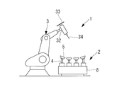
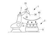
本実施形態に係るワーク支持・加工システム1は、ワークを下方から支持するワーク支持装置(以下「支持装置」という。)2と、支持装置2によって支持されたワークに対して加工を施すことが可能なロボット3などを備える。本実施形態において、ロボット3は、ワークを加工するだけでなく、後述するとおり、準備工程において、支持装置2のロッド4の伸縮位置を変更したり、バキュームパッド5の回動方向を変更したりする。ワーク支持・加工システム1は、本発明のワーク支持システムの一例である。
ワークは、例えば板状部材であり、本実施形態に係る支持装置2は、曲面を有するワークをワークの曲面側から支持することができる。ワークは、種々の加工が施された後、最終的に各種製品の部品となる。製作される部品は、例えば、航空機における尾翼等の航空機部品などの曲面を有するスキンである。なお、ワークは、板状部材に限定されず、他の形状を有する部材でもよい。
支持装置2は、伸縮可能な複数のロッド4が垂直方向に設けられ、ロッド4の上端部に設置された角度調整自在なバキュームパッド5によってワークを保持する。支持装置2は、ロッド4の伸縮長さが調整されたり、バキュームパッド5の設置方向が変更されたりすることによって、1台の支持装置2で曲率の異なる多種類のワークを支持できる。
支持装置2は、複数のロッド4と、バキュームパッド5と、伸縮ロック機構6と、回動ロック機構7と、ロータリーテーブル8などを有する。
ロッド4は、ロータリーテーブル8の上面に設置され、軸方向に伸縮可能な筒状部材である。複数のロッド4は、例えば長方形の領域内に等間隔に配置される。ロッド4は、径の異なる複数の筒状部材が、入れ子状に組み合わされることによって、伸縮可能な構成を有する。
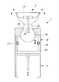
ロッド4には、伸縮ロック機構6が設けられ、伸縮ロック機構6は、ロッド4の軸方向の伸縮位置を保持する。伸縮ロック機構6は、軸方向に伸縮可能な部材の伸縮位置、すなわち、伸縮された長さを固定することが可能な構成を有すればよく、通常用いられる技術を適用できる。伸縮ロック機構6は、図2及び図3に示すように、例えば、ピストン機構9及びくさび部材10によって、ロッド4の位置を固定する。
ピストン機構9は、シリンダ11と、ピストン12などを有する。シリンダ11内には、ピストン12と、くさび部材10が収容される。シリンダ11は、ロッド4の軸方向に沿って、ロッド4の周方向を囲むように設けられる。ピストン12は、シリンダ11内をロッド4の軸方向に沿って移動可能である。ピストン12は、例えば、空気圧、液圧、又は、電磁力によって移動する。図3に示す例では、ピストン12は、ピストンリング13とシリンダ11によって閉鎖されたシリンダ11の下方の空間に空気又は油が供給されたり、電磁力が付与されることによって、上方向へ移動する。また、ピストン12は、下方の空間から空気又は油が排出されたり、付与された電磁力が解除されたりすることによって、下方向へ移動する。
くさび部材10は、ロッド4の外周面とピストン12の内周面の間に配置される。くさび部材10は、ロッド4の周方向に複数配置されてもよい。図2に示す例では、4つのくさび部材10が、ロッド4の周方向に等間隔に配置されている。くさび部材10は、厚さの薄い一端側が下方に位置し、厚さの厚い他端側が上方に位置するように設置され、ピストン12の内周面には、くさび部材10の傾斜形状に応じた溝が形成されている。
伸縮ロック機構6は、ピストン12が下方に位置するとき、くさび部材10の他端側がシリンダ11の天井面に対して自由になるため、ロッド4がくさび部材10によって拘束されることなく、ロッド4が軸方向に沿って移動可能となる。反対に、ピストン12が上方に位置するとき、くさび部材10の一端側がピストン12によって押され、くさび部材10の他端側がシリンダ11の天井面に当接し位置が固定する。このとき、各くさび部材10は、ロッド4の中心方向に向かってピストン12によって押圧され、ロッド4はくさび部材10に対して摺動しづらくなり、ロッド4の軸方向の移動が拘束される。これにより、伸縮ロック機構6は、ロッド4の伸縮位置を保持する。
バキュームパッド5は、ロッド4の上端部にて回動可動に設置される。バキュームパッド5は、吸盤状の真空カップ14と、負圧ホース15と、球面軸受16などを有する。負圧ホース15は、真空ポンプ(図示せず。)と接続されており、真空ポンプ駆動時において、真空カップ14上に載置されたワークとの間の空間に負圧が付与される。球面軸受16は、真空カップ14と接続され、真空カップ14を回動可能に保持する。
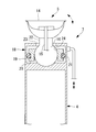
バキュームパッド5には、回動ロック機構7が設けられ、回動ロック機構7は、バキュームパッド5の回動方向を保持する。回動ロック機構7は、回動可能な部材の回動方向を固定することが可能な構成を有すればよく、通常用いられる技術を適用できる。回動ロック機構7は、図4~図6のそれぞれに示すように、例えばピストン機構18によって、球面軸受16の回動方向を固定する。
図4及び図5に示す例では、ピストン機構18は、シリンダ19と、シリンダ19内に収容されたピストン20などを有する。シリンダ19は、ロッド4の先端に設けられ、ピストン20は、シリンダ19内をロッド4の軸方向に沿って移動可能である。ピストン20は、ピストン12は、例えば、空気圧、液圧、又は、電磁力によって移動する。
図4に示す例では、ピストン20は、ピストンリング21とシリンダ19によって閉鎖されたシリンダ19の下方の空間に空気又は油が供給されたり、電磁力が付与されたりすることによって、上方向へ移動する。また、ピストン20は、下方の空間から空気又は油が排出されたり、付与された電磁力が解除されたりすることによって、下方向へ移動する。
真空カップ14と接続された球面軸受16は、ピストン20の上面とシリンダ19の上面によって挟み込み可能な位置に配置される。シリンダ19の上面には、真空カップ14と球面軸受16の接続部分22が貫通可能な開口部23が形成されている。
回動ロック機構7は、ピストン20が下方に位置するとき、球面軸受16がシリンダ19の上面に対して自由になるため、球面軸受16が、ピストン20とシリンダ19によって拘束されることなく、真空カップ14及び球面軸受16が回動可能となる。反対に、ピストン20が上方に位置するとき、球面軸受16がピストン20とシリンダ19によって拘束される。これにより、回動ロック機構7は、バキュームパッド5の回動方向を保持する。
一方、図5に示す例では、図4に示す例と異なり、ピストン20は、ピストンリング21とシリンダ19によって閉鎖されたシリンダ19の上方の空間に空気又は油が供給されたり、電磁力が付与されたりすることによって、下方向へ移動する。また、ピストン20は、上方の空間から空気又は油が排出されたり、付与された電磁力が解除されたりすることによって、上方向へ移動する。
真空カップ14と接続された球面軸受16は、ピストン20の下面とシリンダ19の下面によって挟み込み可能な位置に配置される。シリンダ19の上面とピストン20には、真空カップ14と球面軸受16の接続部分22が貫通可能な開口部23,24が形成されている。
回動ロック機構7は、ピストン20が上方に位置するとき、球面軸受16がシリンダ19の下面に対して自由になるため、球面軸受16が、ピストン20とシリンダ19によって拘束されることなく、真空カップ14及び球面軸受16が回動可能となる。反対に、ピストン20が下方に位置するとき、球面軸受16がピストン20とシリンダ19によって拘束される。これにより、回動ロック機構7は、バキュームパッド5の回動方向を保持する。
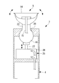
また、図6に示す例では、図4及び図5に示す例のようにシリンダ19がロッド4の延長上に設けられるのではなく、ピストン機構25が、ロッド4の上端部に形成された空間に収容される。ピストン機構25は、シリンダ26と、シリンダ26内に収容されたピストン(図示せず。)と、ピストンに設置されたピストンロッド27などを有する。ピストンは、例えば、空気圧、液圧、又は、電磁力によって移動する。
真空カップ14と接続された球面軸受16は、ピストンロッド27の上面とロッド4の上面によって挟み込み可能な位置に配置される。ロッド4の上面には、真空カップ14と球面軸受16の接続部分22が貫通可能な開口部28が形成されている。
回動ロック機構7は、ピストンロッド27が下方に位置するとき、球面軸受16がロッド4の上面に対して自由になるため、球面軸受16が、ピストンロッド27とロッド4によって拘束されることなく、真空カップ14及び球面軸受16が回動可能となる。反対に、ピストンロッド27が上方に位置するとき、球面軸受16がピストンロッド27とロッド4によって拘束される。これにより、回動ロック機構7は、バキュームパッド5の回動方向を保持する。
ロータリーテーブル8は、複数のロッド4が上面に設置され、鉛直方向に対して平行な回転軸周りに回転可能である。ロータリーテーブル8が回転することによって、複数のロッド4や、複数のロッド4に支持されたワークについて、ロボット3に対する向きを変更することができる。これにより、ロボット3のアーム31やハンド32が可動しやすい位置にロッド4やワークの被加工領域を移動することができ、ロボット3による作業をスムーズかつ精度良く行うことができる。
なお、支持装置2とロボット3は、図1に示すように、共通の台部29に載置されてもよい。
なお、支持装置2とロボット3は、図1に示すように、共通の台部29に載置されてもよい。
ロボット3は、本体30と、アーム31と、ハンド32などを有する。ロボット3は、例えば、6軸制御可能な産業用ロボットであり、位置調整装置の一例である。なお、本発明に係る位置調整装置は、6軸制御可能な産業用ロボットに限定されず、6軸未満のみ制御できる産業用ロボットでもよいし、主軸ヘッドを有する直交軸工作機械などでもよい。
ロボット3の制御方法は、通常用いられる技術を適用でき、以下では、本実施形態に係るワーク支持方法に関する構成及び動作について説明する。
ロボット3のハンド32は、ロッド4又はバキュームパッド5を保持可能とされる。例えば、ハンド32は、チャック機構によってロッド4又はバキュームパッド5を把持してロッド4及びバキュームパッド5を保持してもよい。または、ハンド32に板材33を設置し、バキュームパッド5が板材33を吸引することによって、ハンド32及び板材33がロッド4及びバキュームパッド5を保持してもよい。
なお、ハンド32は、ロッド4又はバキュームパッド5を保持するための構成(チャック機構、板材33など)だけでなく、ワークを加工するための工具34(切削工具、穿孔工具など)が同時に設置されてもよい。
ロボット3は、ハンド32の位置制御を行う。ロボット3は、ハンド32がロッド4又はバキュームパッド5を保持した状態で、予めメモリ等の記録装置に記録されたワークの形状データに基づいてハンド32を移動させて、ロッド4を伸縮させる。すなわち、支持装置2によってワークを支持する際、ワークの下面に相当する位置にバキュームパッド5が位置するように、ハンド32によってロッド4を伸縮させる。より具体的には、バキュームパッド5によって支持されるときのワークの各部位の座標位置に基づいて、各ロッド4の伸縮長さが調整される。
ロッド4によって支持されるワークの各部位の座標位置は、ロッド4の座標位置と対応して決定される。また、ワークを支持するときのロッド4の伸縮長さは、ワークの形状データに基づいて決定される。なお、ハンド32によるロッド4の伸縮動作は、ワークの形状に関する設計データから算出して決定されてもよいし、アーム31及びハンド32を、ロッド4によって実際に支持されているワークまで動かす事前のティーチングによって決定されてもよい。
ロボット3によって伸縮されたロッド4は、伸縮ロック機構6によって伸縮位置が保持される。これにより、ハンド32によるロッド4の保持を解除することができ、別のロッド4の伸縮長さを調整できるようになる。
ロボット3は、ハンド32がバキュームパッド5を保持した状態で、予めメモリ等の記録装置に記録されたワークの形状データに基づいてハンド32を移動させて、バキュームパッド5を回動させる。すなわち、支持装置2によってワークを支持する際、ワークの下面の傾斜方向に、バキュームパッド5の回動方向が一致するように、ハンド32によってバキュームパッド5を回動させる。より具体的には、バキュームパッド5によって支持されるときのワークの各部位の傾斜方向に基づいて、各バキュームパッド5の回動方向が調整される。
ワークを支持するときのバキュームパッド5の傾斜方向は、ワークの形状データに基づいて決定される。なお、ハンド32によるバキュームパッド5の回動動作は、ワークの形状に関する設計データから算出して決定されてもよいし、アーム31及びハンド32を、ロッド4によって実際に支持されているワークまで動かす事前のティーチングによって決定されてもよい。
ロボット3によって回動されたバキュームパッド5は、回動ロック機構7によって回動方向が保持される。これにより、ハンド32によるバキュームパッド5の保持を解除することができ、ハンド32によって別のバキュームパッド5の回動方向を調整できるようになる。
なお、ハンド32に板材33を設置し、バキュームパッド5が板材33を吸引する場合は、ロッド4の伸縮長さの調整と、バキュームパッド5の回動方向の調整をほぼ同時に行うことができ、別々に調整する場合に比べて、作業時間の短縮化を図ることができる。
次に、図7A~図7Fを参照して、本実施形態に係るワーク支持・加工システム1の動作方法について説明する。
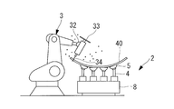
まず、すべてのロッド4及びバキュームパッド5に対して、伸縮ロック機構6及び回動ロック機構7によるロックを解除する(図7A)。そして、図7Bに示すように、ロボット3のハンド32がバキュームパッド5を保持して、ワークの形状データに基づいてハンド32を移動させて、ロッド4を伸縮させる。このとき、ワークの下面に相当する位置にバキュームパッド5が位置するように、ハンド32によってロッド4を伸縮させる。その後、ロボット3によって伸縮されたロッド4は、伸縮ロック機構6によって伸縮位置が保持される。
また、図7Cに示すように、ロボット3のハンド32がバキュームパッド5を保持した状態で、ワークの形状データに基づいてハンド32を移動させて、バキュームパッド5を回動させる。このとき、ワークの下面の傾斜方向にバキュームパッド5の回動方向が一致するように、ハンド32によってバキュームパッド5を回動させる。その後、ロボット3によって回動されたバキュームパッド5は、回動ロック機構7によって回動方向が保持される。
図7B及び図7Cを用いて説明した動作を各ロッド4及びバキュームパッド5に対して繰り返すことで、図7Dに示すように、ロッド4の伸縮長さ及びバキュームパッド5の回動方向が、支持しようとするワークの形状に一致する。そして、真空ポンプを動作させて、バキュームパッド5によるワークの真空吸引が可能な状態とし、図7Eに示すように、バキュームパッド5上にワーク40を設置する。そして、ワーク40が固定された状態で、図7Fに示すように、ロボット3を用いて、ワーク40に対して切削加工等を施す。
以上、本実施形態によれば、各ロッド4において、サーボモータ、アンプ、リニアスケールなどの駆動部や、ガイド、ボールねじなどの伝達機構を設置せずに、ロボット3によって、支持装置2のロッド4の伸縮長さやバキュームパッド5の回動方向を調整できる。また、ロボット3は、準備工程において、支持装置2のロッド4の伸縮位置を変更したり、バキュームパッド5の回動方向を変更したりするだけでなく、支持装置2に支持されたワークに対して、加工を施すことができる。
これにより、ロッド4ごとに駆動装置や駆動力を伝達する伝達機構を設けることなく、簡易な構成でロッド4を伸縮させたりバキュームパッド5を回動させたりすることができる。また、ワークの形状データに応じて、ロッド4を所定の伸縮位置に保持させたり、バキュームパッド5を所定の回動方向に保持させたりすることができる。
ロッド4の伸縮長さやバキュームパッド5の回動方向の調整は、ロッド4ごとに専用に設けられた駆動装置や伝達機構によらず、ロボット3を用いるため、特別なプログラムを使用することなく、ロボット3のプログラムを利用して実施することができる。また、ロッド4の伸縮長さやバキュームパッド5の回動方向を調整するためのロボット3の動作もシンプルであるため、作業者は、従来行っているワークの支持装置2への載置工程と同じ感覚で作業を行うことができる。
上述したとおり、本実施形態によれば、支持装置2は簡易な構成となるため、コストを抑制でき、かつ、故障のリスクを低減できる。また、各ロッドにサーボモータとアンプを接続する場合と異なり、サーボモータとアンプを接続するケーブルが不要になるため、ロッド4を支持するロータリーテーブル8の脱着や回転動作が容易になる。
また、バキュームパッド5の回動方向をロックする回動ロック機構7を備えているため、回動ロック機構7がない場合に比べて、バキュームパッド5の回動方向を正確な角度に設定でき、かつ、バキュームパッド5がワークを強固に支持できる。回動ロック機構7がない場合、バキュームパッド5の回動方向をワークの形状に従わせる必要があり、手間がかかる。また、バキュームパッド5の回動方向をワークに対して面直に固定できない。これに対して、本実施形態によれば、ロボット3がバキュームパッド5の回動方向を調整し、かつ、回動ロック機構7が回動方向を保持することができ、作業にかかる時間や手間を低減できる。さらに、本実施形態では、形状データに基づいた回動方向にバキュームパッド5を設定できるため、バキュームパッド5の回動方向をワークに対して面直に固定できる。そのため、載置前にワークが変形している場合でも、真空吸引を実施することによって、正しい形状に矯正でき、加工精度を向上させることができる。
1 :ワーク支持・加工システム
2 :ワーク支持装置(支持装置)
3 :ロボット
4 :ロッド
5 :バキュームパッド
6 :伸縮ロック機構
7 :回動ロック機構
8 :ロータリーテーブル
9 :ピストン機構
10 :くさび部材
11 :シリンダ
12 :ピストン
13 :ピストンリング
14 :真空カップ
15 :負圧ホース
16 :球面軸受
18 :ピストン機構
19 :シリンダ
20 :ピストン
21 :ピストンリング
22 :接続部分
23 :開口部
24 :開口部
25 :ピストン機構
26 :シリンダ
27 :ピストンロッド
28 :開口部
29 :台部
30 :本体
31 :アーム
32 :ハンド
33 :板材
34 :工具
2 :ワーク支持装置(支持装置)
3 :ロボット
4 :ロッド
5 :バキュームパッド
6 :伸縮ロック機構
7 :回動ロック機構
8 :ロータリーテーブル
9 :ピストン機構
10 :くさび部材
11 :シリンダ
12 :ピストン
13 :ピストンリング
14 :真空カップ
15 :負圧ホース
16 :球面軸受
18 :ピストン機構
19 :シリンダ
20 :ピストン
21 :ピストンリング
22 :接続部分
23 :開口部
24 :開口部
25 :ピストン機構
26 :シリンダ
27 :ピストンロッド
28 :開口部
29 :台部
30 :本体
31 :アーム
32 :ハンド
33 :板材
34 :工具
Claims (5)
- 軸方向に伸縮可能である複数のロッドと、
前記ロッドの上端部にて回動可能に設置され、ワークを保持する保持部と、
前記ロッドの軸方向の伸縮位置を保持する第1ロック部と、
前記ロッド又は前記保持部を保持可能なハンド部を有し、前記ハンド部の位置制御を行う位置調整装置と、
を備え、
前記位置調整装置は、前記ハンド部が前記ロッド又は前記保持部を保持した状態で、予め記録された前記ワークの形状データに基づいて前記ハンド部を移動させて、前記ロッドを伸縮させ、
前記第1ロック部は、前記位置調整装置によって伸縮された前記ロッドの前記伸縮位置を保持するワーク支持システム。 - 前記保持部の回動方向を保持する第2ロック部と、
を更に備え、
前記位置調整装置は、前記ハンド部が前記保持部を保持した状態で、予め記録された前記ワークの形状データに基づいて前記ハンド部を移動させて、前記保持部を回動させ、
前記第2ロック部は、前記位置調整装置によって回動された前記保持部の前記回動方向を保持する請求項1に記載のワーク支持システム。 - 前記複数のロッドが上面に設置され、鉛直方向に対して平行な回転軸周りに回転可能なテーブル部を更に備える請求項1又は2に記載のワーク支持システム。
- 前記保持部は、保持する前記ワークを真空吸引する吸引部を有する請求項1から3のいずれか1項に記載のワーク支持システム。
- 軸方向に伸縮可能である複数のロッドと、
前記ロッドの上端部にて回動可能に設置され、ワークを保持する保持部と、
前記ロッドの軸方向の伸縮位置を保持する第1ロック部と、
前記ロッド又は前記保持部を保持可能なハンド部を有し、前記ハンド部の位置制御を行う位置調整装置と、
を備えるワーク支持システムを用いたワーク支持方法であって、
前記位置調整装置の前記ハンド部が前記ロッド又は前記保持部を保持した状態で、予め記録された前記ワークの形状データに基づいて前記ハンド部を移動させて、前記ロッドを伸縮させるステップと、
前記第1ロック部が、前記位置調整装置によって伸縮された前記ロッドの前記伸縮位置を保持するステップと、
を備えるワーク支持方法。
Priority Applications (3)
| Application Number | Priority Date | Filing Date | Title |
|---|---|---|---|
| CN201980006257.9A CN111465468B (zh) | 2018-01-05 | 2019-01-04 | 工件支承系统以及工件支承方法 |
| US16/956,908 US11383337B2 (en) | 2018-01-05 | 2019-01-04 | Workpiece support system and workpiece support method |
| EP19736152.0A EP3718687B1 (en) | 2018-01-05 | 2019-01-04 | Workpiece support system and workpiece support method |
Applications Claiming Priority (2)
| Application Number | Priority Date | Filing Date | Title |
|---|---|---|---|
| JP2018-000682 | 2018-01-05 | ||
| JP2018000682A JP2019119011A (ja) | 2018-01-05 | 2018-01-05 | ワーク支持システム及びワーク支持方法 |
Publications (1)
| Publication Number | Publication Date |
|---|---|
| WO2019135406A1 true WO2019135406A1 (ja) | 2019-07-11 |
Family
ID=67143700
Family Applications (1)
| Application Number | Title | Priority Date | Filing Date |
|---|---|---|---|
| PCT/JP2019/000014 Ceased WO2019135406A1 (ja) | 2018-01-05 | 2019-01-04 | ワーク支持システム及びワーク支持方法 |
Country Status (5)
| Country | Link |
|---|---|
| US (1) | US11383337B2 (ja) |
| EP (1) | EP3718687B1 (ja) |
| JP (1) | JP2019119011A (ja) |
| CN (1) | CN111465468B (ja) |
| WO (1) | WO2019135406A1 (ja) |
Cited By (2)
| Publication number | Priority date | Publication date | Assignee | Title |
|---|---|---|---|---|
| CN112091574A (zh) * | 2020-11-09 | 2020-12-18 | 烟台工程职业技术学院(烟台市技师学院) | 一种基于汽车动力总成的安装定位装置 |
| WO2026022987A1 (ja) * | 2024-07-24 | 2026-01-29 | ファナック株式会社 | 演算装置、プログラム及び支持システム |
Families Citing this family (6)
| Publication number | Priority date | Publication date | Assignee | Title |
|---|---|---|---|---|
| CN112372278B (zh) * | 2020-11-04 | 2022-07-05 | 江西立讯智造有限公司 | 一种蓝牙耳机充电盒前壳用载具机械手 |
| TWI764405B (zh) * | 2020-12-03 | 2022-05-11 | 財團法人工業技術研究院 | 調整支撐工件方法及可調式支撐工件系統 |
| IT202100008150A1 (it) * | 2021-04-01 | 2022-10-01 | Cms Spa | Sistema di bloccaggio pezzo |
| KR102727915B1 (ko) * | 2022-10-13 | 2024-11-11 | 주식회사 잼스 | 실린더용 클램프를 포함하는 격자형 유연지그 시스템 |
| KR102736329B1 (ko) * | 2022-10-21 | 2024-11-29 | 주식회사 잼스 | 임의의 높이 고정이 가능한 지그 장치 |
| US12509259B1 (en) * | 2023-05-23 | 2025-12-30 | Amazon Technologies, Inc. | Bundling system for banding item(s) |
Citations (6)
| Publication number | Priority date | Publication date | Assignee | Title |
|---|---|---|---|---|
| US5305992A (en) * | 1993-04-19 | 1994-04-26 | The Budd Company | Measuring fixture with gauge ball |
| JP2003001535A (ja) * | 2001-06-20 | 2003-01-08 | Toyota Auto Body Co Ltd | ワーク支持装置 |
| JP2010051980A (ja) * | 2008-08-26 | 2010-03-11 | Honda Motor Co Ltd | 位置決め部保持装置、及びこれを用いたワーク位置決め方法 |
| JP2012125862A (ja) * | 2010-12-14 | 2012-07-05 | Toshiba Mach Co Ltd | 敷ブロックの配置方法、敷ブロック移動用工具、および、その工具を備えた工作機械 |
| JP5766485B2 (ja) | 2011-03-31 | 2015-08-19 | 三菱重工業株式会社 | 真空吸着式サポート治具、これを用いた板状ワークの加工方法および加工体 |
| US20170100839A1 (en) * | 2015-10-08 | 2017-04-13 | Industrial Technology Research Institute | Supporting device, supporting unit system and supporting unit control system |
Family Cites Families (19)
| Publication number | Priority date | Publication date | Assignee | Title |
|---|---|---|---|---|
| JPH071213Y2 (ja) * | 1988-02-17 | 1995-01-18 | 本田技研工業株式会社 | 工作機械のチャック装置 |
| US5094426A (en) * | 1990-04-27 | 1992-03-10 | John Zajac | Metering valve assembly |
| US5485988A (en) * | 1994-05-31 | 1996-01-23 | Nobilec; Leslaw | Clamping means for ski, or the like |
| US6250619B1 (en) | 1998-02-03 | 2001-06-26 | Cna Manufacturing Systems, Inc. | Clamp suitable for use at high temperatures in a flexible tooling apparatus |
| SE0201946D0 (sv) * | 2002-06-25 | 2002-06-25 | Nyfors Teknologi Ab | An arrangement and a method for clamping thin rods |
| SE0201945D0 (sv) * | 2002-06-25 | 2002-06-25 | Nyfors Teknologi Ab | An apparatus and a method for cleaving thin rods |
| DE10350572A1 (de) | 2003-10-30 | 2005-06-16 | Wilhelm Altendorf Gmbh & Co. Kg | Aufspanntisch für Werkstücke in einer Werkzeugmaschine |
| US20070020065A1 (en) * | 2005-07-25 | 2007-01-25 | Kirby Larry D | Workpiece holding apparatus |
| ITTO20110358A1 (it) * | 2011-04-22 | 2012-10-23 | Alenia Aeronautica Spa | Dispositivo di serraggio tarato |
| CN102554660B (zh) * | 2012-01-17 | 2014-04-09 | 清华大学 | 飞机蒙皮的柔性加工系统 |
| JP5516610B2 (ja) * | 2012-01-19 | 2014-06-11 | 株式会社安川電機 | ロボット、ロボットハンドおよびロボットハンドの保持位置調整方法 |
| CN102886699B (zh) * | 2012-10-29 | 2014-11-05 | 江苏科技大学 | 一种加工螺旋桨桨叶的支撑方法 |
| US8967931B1 (en) * | 2013-10-30 | 2015-03-03 | Troy Brownlie | Apparatus for securing cargo |
| CN104625792B (zh) * | 2015-02-12 | 2017-02-01 | 泰安华鲁锻压机床有限公司 | 一种加工板材工件的柔性支撑机构 |
| US10016866B2 (en) * | 2015-05-20 | 2018-07-10 | The Boeing Company | Adjustable part holding fixture, system and method |
| JP2017127929A (ja) | 2016-01-20 | 2017-07-27 | 株式会社フューテックジャパン | 吸着器 |
| CN108526958B (zh) | 2016-08-04 | 2019-12-03 | 上海理工大学 | 一种薄壁零件装夹装置及装夹方法 |
| CN106975955A (zh) * | 2017-05-31 | 2017-07-25 | 南京大地水刀股份有限公司 | 真空吸附数控浮动点阵托架 |
| US11338461B2 (en) * | 2019-04-26 | 2022-05-24 | General Electric Company | System for machining the abradable material of a turbofan engine |
-
2018
- 2018-01-05 JP JP2018000682A patent/JP2019119011A/ja active Pending
-
2019
- 2019-01-04 WO PCT/JP2019/000014 patent/WO2019135406A1/ja not_active Ceased
- 2019-01-04 US US16/956,908 patent/US11383337B2/en active Active
- 2019-01-04 CN CN201980006257.9A patent/CN111465468B/zh not_active Expired - Fee Related
- 2019-01-04 EP EP19736152.0A patent/EP3718687B1/en active Active
Patent Citations (6)
| Publication number | Priority date | Publication date | Assignee | Title |
|---|---|---|---|---|
| US5305992A (en) * | 1993-04-19 | 1994-04-26 | The Budd Company | Measuring fixture with gauge ball |
| JP2003001535A (ja) * | 2001-06-20 | 2003-01-08 | Toyota Auto Body Co Ltd | ワーク支持装置 |
| JP2010051980A (ja) * | 2008-08-26 | 2010-03-11 | Honda Motor Co Ltd | 位置決め部保持装置、及びこれを用いたワーク位置決め方法 |
| JP2012125862A (ja) * | 2010-12-14 | 2012-07-05 | Toshiba Mach Co Ltd | 敷ブロックの配置方法、敷ブロック移動用工具、および、その工具を備えた工作機械 |
| JP5766485B2 (ja) | 2011-03-31 | 2015-08-19 | 三菱重工業株式会社 | 真空吸着式サポート治具、これを用いた板状ワークの加工方法および加工体 |
| US20170100839A1 (en) * | 2015-10-08 | 2017-04-13 | Industrial Technology Research Institute | Supporting device, supporting unit system and supporting unit control system |
Non-Patent Citations (1)
| Title |
|---|
| See also references of EP3718687A4 |
Cited By (3)
| Publication number | Priority date | Publication date | Assignee | Title |
|---|---|---|---|---|
| CN112091574A (zh) * | 2020-11-09 | 2020-12-18 | 烟台工程职业技术学院(烟台市技师学院) | 一种基于汽车动力总成的安装定位装置 |
| CN112091574B (zh) * | 2020-11-09 | 2021-01-29 | 烟台工程职业技术学院(烟台市技师学院) | 一种基于汽车动力总成的安装定位装置 |
| WO2026022987A1 (ja) * | 2024-07-24 | 2026-01-29 | ファナック株式会社 | 演算装置、プログラム及び支持システム |
Also Published As
| Publication number | Publication date |
|---|---|
| US11383337B2 (en) | 2022-07-12 |
| EP3718687A4 (en) | 2021-01-20 |
| US20200391333A1 (en) | 2020-12-17 |
| JP2019119011A (ja) | 2019-07-22 |
| EP3718687A1 (en) | 2020-10-07 |
| CN111465468A (zh) | 2020-07-28 |
| CN111465468B (zh) | 2022-03-15 |
| EP3718687B1 (en) | 2022-02-16 |
Similar Documents
| Publication | Publication Date | Title |
|---|---|---|
| WO2019135406A1 (ja) | ワーク支持システム及びワーク支持方法 | |
| US11945064B2 (en) | Static flexible tooling system | |
| US7168898B2 (en) | Process and device for machining by windowing of non-deformable thin panels | |
| CN105492162B (zh) | 工件保持设备 | |
| EP2808110B1 (en) | Drilling apparatus and drilling method | |
| RU2672964C2 (ru) | Система для поддержки обрабатываемой детали | |
| JP6882258B2 (ja) | 加工ステーション | |
| US20070020065A1 (en) | Workpiece holding apparatus | |
| EP0395687A1 (en) | Surfacing machine | |
| CN101633123A (zh) | 轴类零件的装夹方法及专用筒型夹具 | |
| CN117067140B (zh) | 一种装夹工装、调姿方法 | |
| JP3741251B2 (ja) | 穿孔装置 | |
| CN219901130U (zh) | 一种薄壁筒状工件用夹具 | |
| CN114867580B (zh) | 机床及其操作方法 | |
| CN104507638B (zh) | 用于动态地紧固用于机加工的零件的紧固工具 | |
| JPH0531639A (ja) | 長尺ワークの加工装置 | |
| US20240246182A1 (en) | Work support member and adjustment mechanism | |
| CN104162888B (zh) | 六自由度浮动机构 | |
| CN118268779B (zh) | 一种双工位焊接机器人及其控制系统 | |
| US20240326260A1 (en) | Cable drive for positioning an end effector for working on a part | |
| CN120955031A (zh) | 一种晶圆夹持翻转机构及其控制方法 | |
| WO2001058627A1 (en) | Tool holder assembly | |
| JP2006123010A (ja) | シャフト加工装置 | |
| JP4655228B2 (ja) | 多関節ロボットおよび多関節ロボットの移送方法 | |
| JP2025177696A (ja) | ワーク保持装置 |
Legal Events
| Date | Code | Title | Description |
|---|---|---|---|
| 121 | Ep: the epo has been informed by wipo that ep was designated in this application |
Ref document number: 19736152 Country of ref document: EP Kind code of ref document: A1 |
|
| NENP | Non-entry into the national phase |
Ref country code: DE |
|
| ENP | Entry into the national phase |
Ref document number: 2019736152 Country of ref document: EP Effective date: 20200629 |