WO2019136885A1 - 一种薄片材料面向导热性能稳态测试方法 - Google Patents
一种薄片材料面向导热性能稳态测试方法 Download PDFInfo
- Publication number
- WO2019136885A1 WO2019136885A1 PCT/CN2018/085404 CN2018085404W WO2019136885A1 WO 2019136885 A1 WO2019136885 A1 WO 2019136885A1 CN 2018085404 W CN2018085404 W CN 2018085404W WO 2019136885 A1 WO2019136885 A1 WO 2019136885A1
- Authority
- WO
- WIPO (PCT)
- Prior art keywords
- sheet
- test
- tested
- heat
- thermal conductivity
- Prior art date
- Legal status (The legal status is an assumption and is not a legal conclusion. Google has not performed a legal analysis and makes no representation as to the accuracy of the status listed.)
- Ceased
Links
Images
Classifications
-
- G—PHYSICS
- G01—MEASURING; TESTING
- G01N—INVESTIGATING OR ANALYSING MATERIALS BY DETERMINING THEIR CHEMICAL OR PHYSICAL PROPERTIES
- G01N25/00—Investigating or analyzing materials by the use of thermal means
- G01N25/18—Investigating or analyzing materials by the use of thermal means by investigating thermal conductivity
-
- G—PHYSICS
- G01—MEASURING; TESTING
- G01N—INVESTIGATING OR ANALYSING MATERIALS BY DETERMINING THEIR CHEMICAL OR PHYSICAL PROPERTIES
- G01N25/00—Investigating or analyzing materials by the use of thermal means
- G01N25/16—Investigating or analyzing materials by the use of thermal means by investigating thermal coefficient of expansion
Definitions
- the invention relates to a method for testing the thermal conductivity of a material, and more particularly to a method for testing the thermal conductivity of a sheet for a test specimen, and is applicable to uniform or non-uniform, isotropic or anisotropic thermal conductivity. Sheet.
- the thermal conductivity of materials is critical to thermal design. Accurate testing of thermal conductivity of materials is the basis of system design and the basis for production quality control.
- the thermal conductivity of materials is generally expressed by the thermal conductivity coefficient. In a few cases, the thermal diffusivity parameter is also used for characterization. In the case of known density and specific heat capacity, one can calculate the other.
- the thermal conductivity of these materials is closely related to the structure of the material, the molding process, etc. If a thick sample that meets the test requirements is specially prepared, the thermal conductivity of the sample may differ from the material properties in the real application, so it is necessary to directly Sheet samples were tested.
- the conventional test method for sheet materials is mainly the flash method, which is mainly used to test the longitudinal thermal conductivity.
- Some manufacturers' thermal conductivity testers provide special brackets that allow the flash method to test for thermal conductivity, but in practice there are problems with poor accuracy and repeatability.
- the flash method is an unsteady method.
- the thickness direction cannot be approximated as a uniform material, and the unsteady method test results and the steady state method test results are There is a deviation in the ratio; in practical applications, these materials are generally in an approximately steady state heat transfer state, so the steady-state test results can better reflect the performance of the material in practical applications.
- thermal conductivity steady-state test methods generally require measurement of heat flux density and temperature gradient on the sample during thermal equilibrium.
- the thermal conductivity is defined as the ratio of the two.
- the heat flux density at the test point is generally not directly measurable and needs to be estimated by the heat flux density on the reference material or by the total heat transfer divided by the cross-sectional area. Therefore, the conventional steady-state method generally requires that the heat flux density in the sample be uniformly distributed on the heat transfer section, and the total heat flow in the upstream and downstream sections in the heat conduction process is consistent. To do this, many measures need to be taken in the control of sample preparation and test conditions.
- the sample heat transfer cross-section size is large enough to reduce the influence of surface heat transfer, and there is enough distance from the heat source or contact surface to the temperature measurement point to eliminate uneven heating or The effect of uneven thermal resistance, the surface is wrapped with insulating material or protective heating to improve heat flow uniformity and continuity in the sample, and so on.
- the thermal conductivity test of the sheet material since the thickness direction of the sample is small, the total heat flux through the heat transfer section for heat transfer is small, the surface heat loss has a great influence on the test, and the heat flow uniformity and continuity in the sample. Sex is difficult to guarantee, resulting in poor test accuracy and repeatability.
- the technical problem to be solved by the present invention is to propose a steady state test method suitable for the thermal conductivity of the sheet material, which can reduce the influence of surface heat loss on the test.
- the sheet to be tested is continuously heated at a constant power to cause heat conduction in the plane direction. After the sheet to be tested reaches thermal equilibrium, the surface temperature distribution of the sheet is measured and recorded; the section of heat conduction in a completely cut sheet is selected as a test section, and the cross section and the surface of the sheet are tested.
- the intersection line is the test line; according to the surface temperature field data of the sheet, the temperature gradient along the normal direction of each point on the test line is calculated and integrated along the test line, and then multiplied by the thickness of the sheet, the result is recorded as A; the estimation test process
- the total heat flow through the test section is recorded as PT; the PT is divided by A to obtain the thermal conductivity of the sheet material.
- a reference sheet is prepared using a reference material having a known thermal conductivity and a thermal conductivity similar to that of the sheet to be tested, instead of testing the sheet to be tested; adjusting the heating power and checking the heat transfer upstream temperature of the cross section until the measured temperature average value is measured. It is consistent with the test of the sheet to be tested; the temperature gradient along the normal direction of each point on the test line is calculated and integrated along the test line, and then multiplied by the thickness of the sheet and the thermal conductivity of the reference sheet, the result is recorded as PTR; The heating power at the time of the sheet test is PS, and the heating power at the time of the sheet test is PSR.
- the surface is divided into a plurality of non-overlapping single-connected regions, and the central portion of each single-connected region is locally heated until the state of thermal equilibrium, and the surrounding heating region is selected.
- the closed loop line located in the single connected region is a test line, and the calculation result is the apparent thermal conductivity of the single connected region; the test results of all the single connected regions are combined to obtain a quantitative evaluation of the spatial distribution of the thermal conductivity of the sheet.
- the present invention provides the following technical solution for simultaneously measuring two thermal conductivity coefficients for a sheet material facing thermal anisotropy:
- the sheet to be tested is continuously heated at a constant power to cause heat conduction in the plane direction. After the sheet to be tested reaches thermal equilibrium, the surface temperature distribution of the sheet is measured and recorded, and then the thermal conductivity of the two heat transfer spindle directions is calculated as follows:
- a rectangular coordinate system is established on the sheet to be tested with two orthogonal heat transfer main axes directions for the X and Y axes, respectively, and the thermal conductivity coefficients in the two directions are respectively Kx and Ky; and at least two completely cut sheets are selected.
- the section of heat conduction is the test section, and the intersection of the test section and the surface of the sheet is the test line, denoted as L(i), where i is the number that distinguishes the different test lines.
- the invention has the beneficial effects that the invention does not use the single point heat flux density to calculate the thermal conductivity, but integrates the heat flux density on the heat transfer section, and uses the continuity of the total heat flow to calculate the thermal conductivity, so the test does not require Produces a uniform heat flow field, reduces the heat source requirements, and can conduct thermal conductivity measurement based on a small test area, which brings many advantages: First, because the surface heat loss and heat dissipation area are positively correlated, the test area is reduced. The surface heat loss can be effectively reduced. Second, the convection and radiation heat dissipation model on the surface of the test area is related to the surrounding environment. Therefore, the larger the area, the more complicated the interference factor.
- test area can improve the stability of the convection and radiation heat dissipation model. And repeatability, thereby improving the accuracy of surface heat loss estimation in the test area; third, since the test is based on a small test area, the test result represents only the apparent thermal conductivity of the material in the local area, so the method is also available To evaluate the distribution characteristics of the non-uniform material in the plane with thermal conductivity.
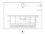
- Embodiment 1 is a cross-sectional structure of a test system according to Embodiment 1 of the present invention.
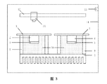
- FIG. 3 is a cross-sectional structure of a test system according to Embodiment 2 of the present invention.
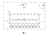
- FIG. 5 is a cross-sectional structure of a test system according to Embodiment 3 of the present invention.
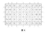
- FIG. 6 is a schematic diagram of dividing a surface of an uneven sheet to be tested into a plurality of single connected regions in Embodiment 3 of the present invention.
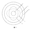
- FIG. 7 is a diagram showing the division of the surface area of the sheet to be tested when calculating the thermal conductivity of two plane directions in Embodiment 4 of the present invention.
- the cross-sectional structure of the test system is as shown in FIG. 1 : the electric heating device 1 is locally heated by the heat conducting column 2 to measure the middle portion of the sheet 3 at a constant power, and the heat flows through the heat conducting ring seat 4 to the heat sink 5; the electric heating device 1 and the heat conducting column 2 The periphery, and the lower portion of the sheet 3 to be tested, are filled with a heat insulating material 6; the thermal imager 7 is measuring the sheet 3; the test device bodies are all located in the incubator 8, and the temperature sensor 9 measures the temperature of the incubator.
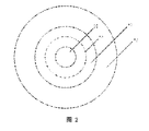
- the surface area of the sample is divided as shown in FIG. 2: the heating area 10 is located in the middle of the sample, the test area 11 surrounds the heating area, and the heat dissipation area 12 is located at the outermost side; the heating area 10 and the heat dissipation area 12 both have heat conduction in the direction of the vertical sheet surface, and the test area 11 can be approximated to only face heat conduction; a test line 13 located in the middle of the test area 11 is selected, the heat transfer section of the corresponding vertical sheet surface completely intercepting the heat transfer from the heating zone 10 to the heat sinking zone 12.
- test steps are as follows:
- a surface of the sheet 3 to be tested is coated with a high emissivity black body coating, which is to be dried and placed in the system shown in Fig. 1 for testing, the surface of the black body coating is applied toward the thermal imager 7;
- the emissivity should be calibrated in advance, or data from the black body coating supplier, which will be provided to the thermal imager 7 to correct the temperature measurement data.
- the electric heating device 1 starts constant power continuous heating, and the thermal imager 7 continuously collects the surface temperature data of the sheet 3 to be tested, and checks its stability until the temperature change at any point on the surface of the sheet 3 to be tested does not exceed 0.2 ° C for 5 minutes; At this time, the sample is considered to enter a thermal equilibrium state, the surface temperature field data is recorded at this time, the electric heating source 1 heating power PS is recorded, and then the thermal conductivity of the sheet 3 to be tested is calculated.
- the method for calculating the thermal conductivity is as follows:
- T is the thermodynamic temperature of the observation point
- T a is the thermodynamic temperature of the incubator
- S is the surface area of the sample corresponding to each pixel point
- ⁇ is the surface emissivity of the sample
- ⁇ It is the Stefan-Boltzmann constant.
- the convection loss is:
- h s is the surface convective heat transfer coefficient, which can be set empirically, or determined according to simulation, or adjusted according to test results of reference materials with known thermal conductivity;
- the surface heat loss PL of the sample during the test is the sum of the radiant heat loss and the convective heat loss at each point in the surrounding area of the test line:
- ⁇ is the set of pixel point coordinates in the area enclosed by the test line.
- the method does not need to achieve uniform heat flow, so the length of the heat-conducting column, the area of the heating area, the length of the test area, etc. can be small; for example, when testing a 50-micron thick thermally conductive graphite film, the diameter of the heat-conducting column is taken as 5 mm.
- the length of the heat-conducting column is 10mm, and the test line selects a ring with a diameter of 10mm concentric with the heat-conducting column.
- the heat-dissipating area by convection and radiation is about 78.5mm 2 when tested, and the contact area with the heat-insulating material is about 235.6mm 2 .
- the test results represent the apparent thermal conductivity of the material in a small area, it can be used to quantitatively evaluate the size of the non-uniform material in different regions of the thermal conductivity.
- the cross-sectional structure of the test system is shown in Fig. 3: the main electric heating device 1 performs local heating with a constant power through the leading hot column 2 to measure the middle portion of the sheet 3, and heat flows through the heat conducting ring seat 4 to the heat sink 9; symmetrical, reference electric heating device 5, by reference to the heat conducting column 6, the reference sheet 7 is locally heated at a constant power, the heat passes through the heat conducting ring seat 8, flows to the heat sink 9; the main electric heating device 1 and the leading heat column 2, the lower portion of the sheet 3 to be tested, reference The periphery of the electric heating device 5 and the reference heat transfer column 6 and the lower portion of the reference sheet 7 are filled with a heat insulating material 10; the thermal imager 11 is mounted on the one-dimensional translation stage 12, which can be directly above the sheet 3 to be tested and the reference sheet 7 The temperature measurement is moved back and forth directly; the test device bodies are all located in the incubator 14, and the temperature sensor 13 measures the oven temperature.
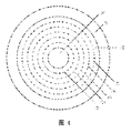
- the surface area of the sample is divided as shown in FIG. 4: the heating area 20 is located in the middle of the sample, the test area 22 surrounds the heating area, and the heat dissipation area 21 is located at the outermost side; the heating area 20 and the heat dissipation area 22 both have heat conduction in the direction of the vertical sheet surface, and the test area 22 can be approximated only for heat conduction; five test lines 23, 24, 25, 26, 27 located in the middle of the test area 22 are selected, and the heat transfer sections of the vertical sheet surfaces corresponding to the five test lines are completely cut off from the heating area 20 to the heat dissipation area. 21 heat conduction.
- test steps are as follows:
- a surface of the test sheet 3 and the reference sheet 7 is coated with a high emissivity black body coating, which is to be dried and placed in the system shown in Fig. 3 for testing, the surface of the black body coating is applied toward the thermal imager 11;
- the emissivity of the coating layer should be calibrated in advance, or data from the black body coating supplier, which will be provided to the thermal imager 11 to correct the temperature measurement data.
- the thermostat 14 starts temperature control, and the internal temperature of the incubator 14 is adjusted to the set test temperature.
- the main electric heating device 1 starts constant power and continues to heat, the thermal imager 11 moves directly above the sheet 3 to be tested, continuously collects the surface temperature data of the sheet 3 to be tested, and checks its stability until the sheet 3 to be tested for 5 minutes in a row. The temperature change at any point on the surface does not exceed 0.2 ° C. At this time, the sample is considered to enter a thermal equilibrium state, and the surface temperature field data at this time is recorded.
- the reference electric heating device 5 starts heating at the set power, the thermal imager 11 moves directly above the reference sheet 7, continuously collects the surface temperature data of the reference sheet 7, and checks its stability until the surface of the reference sheet 7 is arbitrarily selected within 5 minutes.
- the point temperature does not vary by more than 0.2 °C.
- step 5 comparing the average temperature of the reference sheet 7 and the sheet 3 to be tested in the heating zone 20 and the test zone 22, if the difference between them is within 0.2 ° C, then jump to the next step; otherwise, if the reference sheet 7 average temperature Higher, the heating power of the reference electric heating source 5 is reduced, and then jumps to step 3); otherwise, the heating power of the reference electric heating source 5 is increased, and then jumps to step 3).
- the method for calculating the thermal conductivity is as follows:
- k ref is the thermal conductivity of the reference sheet.
- the heat transfer path, so the heat loss models of the two are basically the same; by adjusting the heating power to make the temperature of the two uniform, the heat loss power is also basically the same; the heat loss on the reference sheet 7 can be based on the known thermal conductivity of the reference material.
- the calculation results in a good approximation of the heat loss power of the sheet 3 to be tested, thereby reducing the effect of heat loss on the thermal conductivity test results.
- the thermal conductivity is calculated by a plurality of test loop lines and then averaged, so that the influence of the temperature measurement data noise can be reduced.
- the sectional structure of the test system is shown in Fig. 5: the sheet 3 to be tested is arranged on the heat conducting ring seat 4, and the laser light emitting part 1 is fixed on the two-dimensional electric stage 2, and a circular spot laser having a diameter of 2 mm can be emitted at a constant power, and projected.
- the lower surface of the sheet 3 is measured; after the sheet to be tested is heated, the heat passes through the heat conducting ring seat 4 and flows to the heat sink 5; the thermal imager 6 is located directly above the sheet 3 to be tested; the main body of the testing device is located in the incubator 7, and the temperature sensor 8 Measure the oven temperature.
- the thermal conductivity coefficient of the sheet 3 to be tested is unevenly distributed.
- the surface is divided into a series of non-overlapping single connected regions, such as an equidistant grid, or appropriately adjusted according to prior knowledge, such as heat conduction at the edge. If the coefficient uniformity is worse, the mesh is more dense, or divided according to other qualitative evaluation results; an example of the regional division result is shown in Fig. 6, wherein the solid large rectangular frame indicates the slice 3 to be tested, horizontal and vertical.
- the straight imaginary line indicates the divided single connected region boundary; when testing each single connected region, the heating region is the solid circle in Fig. 6, and the test loop is the dotted ellipse or circle in Fig. 6.
- test steps are as follows:
- Both surfaces of the sheet 3 to be tested are coated with a high emissivity black body coating, which is to be dried and placed in the system shown in Fig. 5; the emissivity of the black body coating layer in the sensitive wavelength range of the thermal imager 6
- the absorption rate of the laser 1 wavelength should be calibrated in advance, or the data of the black body coating supplier is used, and the emissivity data is supplied to the thermal imager 6 to correct the temperature measurement data, and the absorption rate data is used to correct the actual effective heating power of the laser 1.
- the laser 1 starts to output a constant power, and the thermal imager 6 continuously collects the surface temperature data of the sheet 3 to be tested, and checks the stability until the temperature of any surface of the sheet 3 to be tested does not exceed 0.2 ° C for 5 minutes; The sample enters the thermal equilibrium state, the surface temperature field data is recorded at this time, and the laser power PS is recorded.
- T is the thermodynamic temperature of the observation point
- T a is the thermodynamic temperature of the incubator
- S is the surface area of the sample corresponding to each pixel point
- ⁇ is the surface emissivity of the sample
- ⁇ It is the Stefan-Boltzmann constant.
- the convection loss is:
- h s is the surface convection heat transfer coefficient
- the surface surface heat loss PL of the test is the sum of the radiant heat loss and the convective heat loss at each point of the test loop enveloping area:
- ⁇ is the set of pixel point coordinates in the area surrounded by the test loop.
- the method allows the thermal conductivity of the sample to be tested to have non-uniformity as a whole, and is only required to be substantially uniform in a small range, and quantitative evaluation of the spatial distribution of thermal conductivity can be obtained; for example, when the laser spot diameter is 2 mm Select a 5mm diameter test loop to obtain a 5mm spatial resolution of the thermal conductivity spatial distribution test results.
- the cross-sectional structure of the test system is as shown in FIG. 1 : the electric heating device 1 is locally heated by the heat conducting column 2 to measure the middle portion of the sheet 3 at a constant power, and the heat flows through the heat conducting ring seat 4 to the heat sink 5; the electric heating device 1 and the heat conducting column 2 The periphery, and the lower portion of the sheet 3 to be tested, are filled with a heat insulating material 6; the thermal imager 7 is measuring the sheet 3; the test device bodies are all located in the incubator 8, and the temperature sensor 9 measures the temperature of the incubator.
- the surface area of the sample is divided as shown in Fig. 7: the heating area 10 is located in the middle of the sample, the test area 11 surrounds the heating area, and the heat dissipation area 12 is located at the outermost side; the heating area 10 and the heat dissipation area 12 both have heat conduction in the direction of the vertical sheet surface, and the test area 11 can be approximated only for heat conduction; two test lines 13 and test lines 14 located in the test area 11 are selected, the heat transfer sections of the corresponding vertical sheet surfaces completely intercepting the heat conduction from the heating area 10 to the heat dissipation area 12, and Both use a closed loop like elliptical shape, but the long axis directions of the two test lines are perpendicular to each other.
- test steps are as follows:
- a surface of the sheet 3 to be tested is coated with a high emissivity black body coating, which is to be dried and placed in the system shown in Fig. 1 for testing, the surface of the black body coating is applied toward the thermal imager 7;
- the emissivity should be calibrated in advance, or data from the black body coating supplier, which will be provided to the thermal imager 7 to correct the temperature measurement data.
- the electric heating device 1 starts constant power continuous heating, and the thermal imager 7 continuously collects the surface temperature data of the sheet 3 to be tested, and checks its stability until the temperature change at any point on the surface of the sheet 3 to be tested does not exceed 0.2 ° C for 5 minutes; At this time, the sample is considered to enter a thermal equilibrium state, the surface temperature field data is recorded at this time, the electric heating source heating power PS is recorded, and then the thermal conductivity of the sheet to be tested is calculated.
- the method for calculating the thermal conductivity is as follows:
- a rectangular coordinate system is established on the sheet to be tested with two orthogonal heat transfer main axes directions for the X and Y axes, and the thermal conductivity in both directions is Kx and Ky, respectively.
- the radiation loss is:
- T is the thermodynamic temperature of the observation point
- T a is the thermodynamic temperature of the incubator
- S is the surface area of the sample corresponding to each pixel point
- ⁇ is the surface emissivity of the sample
- ⁇ It is the Stefan-Boltzmann constant.
- the convection loss is:
- h s is the surface convection heat transfer coefficient
- ⁇ 1 is the set of pixel point coordinates in the area surrounded by the test line 13
- ⁇ 2 is the set of pixel point coordinates in the area surrounded by the test line 14.
- the results of the unknown Kx and Ky solution are the thermal conductivity of the X and Y axes.
Landscapes
- Physics & Mathematics (AREA)
- Health & Medical Sciences (AREA)
- Life Sciences & Earth Sciences (AREA)
- Chemical & Material Sciences (AREA)
- Analytical Chemistry (AREA)
- Biochemistry (AREA)
- General Health & Medical Sciences (AREA)
- General Physics & Mathematics (AREA)
- Immunology (AREA)
- Pathology (AREA)
- Investigating Or Analyzing Materials Using Thermal Means (AREA)
Abstract
本发明公开了一种针对薄片状测试样品面向导热性能的稳态测试方法。本发明对薄片样品局部加热直到热平衡状态,然后根据传热截面上温度梯度的积分来计算导热系数。本发明特点在于不要求热流均匀,可以基于薄片样品很小的区域进行测试,表面热损失功率较小,减小表面散热对导热系数测试准确性的影响;同时该方法表征的是薄片小范围的表观导热系数,因此通过改变测试区域可获得非均匀薄片导热系数空间分布的定量评估;基于相同思想,将方法略作修改后也适用于面向导热各向异性的薄片材料。
Description
本发明涉及一种材料导热性能测试方法,更具体的是一种针对薄片测试样品的面向导热性能稳态测试方法,并且可适用于面向导热性能均匀或非均匀、各向同性或各向异性的薄片。
材料导热性能对热设计至关重要,准确测试材料导热性能是系统设计的基础,也是生产品质控制的依据。材料导热性能一般采用导热系数表示,少数时候也使用热扩散率参数表征,在已知密度和比热容的情况下,二者知其一可计算另一个。
导热性能测试目前有很多方法和标准,但这些方法大多针对传统材料,一般要求测试样品是均匀材料,是各向同性的。随着技术的发展,各种新材料和新工艺出现,出现一些传统方法测试效果不理想的情形。某些应用中的器件几何尺寸在一个维度上显著小于其它两个维度,表现出“薄”的特征,比如导热石墨膜,冲压或压铸等工艺制造的薄壁金属件等。很多时候,这些材料的导热性能与材料的结构、成型工艺等密切相关,如果专门制作满足测试要求的厚样品,则该样品的导热性能与真实应用中的材料性能可能存在差异,因此需要直接对薄片样品进行测试。
薄片类材料常规测试方法主要是闪光法,该方法主要用于测试纵向导热系数。某些厂家的导热系数测试仪提供特殊支架,使得闪光法也可以测试面向导热系数,但实践中存在准确性和重复性差的问题。更关键的是,闪光法是一种非稳态方法,对于导热石墨膜等具有多层结构的复合材料,其厚度方向不可近似为均匀材料,非稳态方法测试结果和稳态方法测试结果相比会出现偏差;而在实际应用中,这些材料一般处于近似稳态传热状态,因此稳态法测试结果可以更好的反映该材料在实际应用中的性能表现。
常规的导热系数稳态测试方法,一般需要测量热平衡状态时样品 上的热流密度和温度梯度,导热系数定义为二者比值。测试点的热流密度一般无法直接测量,需要通过参考材料上的热流密度进行估计,或者根据传热总功率除以截面积来计算。因此常规稳态方法测试时一般要求样品内热流密度在传热截面上分布均匀,且热传导过程中上下游截面上的热流总功率保持一致。为此需要在制样和测试条件控制上采取很多措施,比如样品传热截面尺寸足够大以减小表面换热的影响,从热源或接触面到测温点有足够距离以消除加热不均匀或热阻不均匀的影响,表面采用绝热材料包裹或者进行保护加热以提高样品中热流均匀性和连续性,等等。但是对于薄片材料的面向导热系数测试,由于样品厚度方向尺寸很小,面向传热时通过传热截面的热流总功率很小,表面热损失对测试影响很大,样品中热流的均匀性和连续性都难以保证,导致测试准确性和重复性较差。
发明内容
本发明要解决的技术问题是:提出一种适合薄片材料面向导热性能的稳态测试方法,可以减小表面热损失对测试的影响。
本发明解决技术问题所采取的技术方案为:
对待测薄片以恒定功率持续加热,引起平面方向的热传导,在待测薄片达到热平衡后,测量并记录薄片表面温度分布;选择一个完全截断薄片中热传导的截面为测试截面,测试截面与薄片表面的交线为测试线;根据薄片表面温度场数据,计算测试线上各点沿法线方向的温度梯度并将其沿测试线进行线积分,然后乘以薄片厚度,结果记为A;估计测试过程中通过测试截面的热流总功率,记为PT;将PT除以A,得到薄片材料面向导热系数。
进一步说,采用导热系数已知且面向导热性能与待测薄片相近的参考材料制作参考薄片,替代待测薄片进行测试;调节加热功率并检查热平衡时测试截面传热上游温度,直到所测温度均值与待测薄片测试时一致;计算测试线上各点沿法线方向的温度梯度并将其沿测试线进行线积分,然后乘以薄片厚度和参考薄片面向导热系数,结果记为PTR;记待测薄片测试时的加热功率为PS,参考薄片测试时的加热功率为PSR,计算待测薄片测试过程中通过测试截面的热流总功率 PT的方法为:PT=PS-(PSR-PTR)。
进一步说,对于面向导热系数在平面不同区域有显著差异的薄片,将其表面划分为多个不重叠的单连通区,对每个单连通区中部进行局部加热直到热平衡状态,选择包围加热区域且位于该单连通区内的闭合环线为测试线,计算结果为该单连通区的表观面向导热系数;综合所有单连通区测试结果,得到该薄片面向导热系数空间分布的定量评估。
基于本发明相同思路,针对面向导热各向异性的薄片材料,本发明提供如下技术方案同时测量两个面向导热系数:
对待测薄片以恒定功率持续加热,引起平面方向的热传导,在待测薄片达到热平衡后,测量并记录薄片表面温度分布,然后采用如下方法计算两个传热主轴方向的导热系数:
1)在待测薄片上以两个正交的传热主轴方向分别为X、Y轴方向建立直角坐标系,记两个方向的导热系数分别为Kx和Ky;选择至少两个完全截断薄片中热传导的截面为测试截面,测试截面与薄片表面的交线为测试线,记为L(i),其中i为区分不同测试线的编号。
2)对每条测试线L(i),计算测试线上各点沿X轴方向和Y轴方向的温度梯度,取二者沿测试线法线方向的分量沿测试线进行线积分,然后乘以薄片厚度,结果分别记为Ax(i)和Ay(i)。
3)估计测试过程中通过测试线L(i)对应测试截面的热流总功率,记为PT(i)。
4)求解如下形式的二元一次方程组,得到薄片沿两个传热主轴方向的面向导热系数Kx和Ky:Kx*Ax(i)+Ky*Ay(i)=PT(i)。
本发明的有益效果:本发明并不利用单点热流密度来计算导热系数,而是对传热截面上的热流密度进行积分,利用热流总功率的连续性来计算导热系数,因此测试时不要求产生均匀热流场,降低对热源的要求,并且可以基于很小的测试区域进行导热系数测量,这带来多方面好处:第一,由于表面热损失和散热面积正相关,因此减小测试区域可以有效减小表面热损失;第二,测试区域表面的对流和辐射散热模型和周围环境有关,因此面积越大则干扰因素越复杂,减小测试 区域面积可以提高对流和辐射散热模型的稳定性和重复性,从而提高测试区域表面热损失估计的准确性;第三,由于测试基于很小的测试区域进行,测试结果代表的只是该局部区域内材料的表观导热系数,因此该方法也可用来评估非均匀材料面向导热系数在平面内的分布特性。
图1为本发明实施方式1的测试系统剖面结构;
图2为本发明实施方式1计算导热系数时的样品表面区域划分;
图3为本发明实施方式2的测试系统剖面结构;
图4为本发明实施方式2计算导热系数时的待测样品和参考样品表面区域划分;
图5为本发明实施方式3的测试系统剖面结构;
图6为本发明实施方式3中划分不均匀待测薄片表面为多个单连通区的示意图;
图7为本发明实施方式4中计算两个平面方向导热系数时待测薄片表面区域划分。
为了使本发明的目的、技术方案及优点清楚明白,以下结合附图对本发明做进一步说明:
实施方式1
测试系统剖面结构如图1所示:电加热装置1通过导热柱2对待测薄片3中部以恒定功率进行局部加热,热量通过导热环座4流向热沉5;电加热装置1和导热柱2的四周,以及待测薄片3的下部,都采用绝热材料6填充;热像仪7正对待测薄片3;测试装置主体均位于恒温箱8中,温度传感器9测量恒温箱温度。
样品表面区域划分如图2所示:加热区域10位于样品中部,测试区域11包围加热区域,散热区域12位于最外侧;加热区域10和散热区域12均有垂直薄片表面方向的热传导,而测试区域11可近似为只有面向热传导;选择一条位于测试区域11中部的测试线13,其对应的垂直薄片表面的传热截面完全截断从加热区域10向散热区域 12的热传导。
测试步骤如下:
1)对待测薄片3的一个表面涂覆高发射率黑体涂料,待干燥后放入图1所示系统中进行测试,涂覆黑体涂料的表面朝向热像仪7;所述黑体涂覆层的发射率应事先标定,或者采用黑体涂料供应商的数据,该发射率将提供给热像仪7以便校正测温数据。
2)电加热装置1开始恒定功率持续加热,热像仪7持续采集待测薄片3表面温度数据,检查其稳定性,直到连续5分钟内待测薄片3表面任意点温度变化不超过0.2℃;此时认为样品进入热平衡状态,记录此时表面温度场数据,记录电加热源1加热功率PS,然后计算待测薄片3面向导热系数。
计算导热系数方法如下:
1)计算温度梯度在测试截面上的积分:对测试线13上各点,根据热像仪7测量的离散温度场数据,通过相邻点差分或者局部曲线拟合方法计算该点沿测试线法线方向向外的温度梯度,再通过数值积分方法计算该温度梯度沿测试线的线积分,将其乘以薄片厚度,得到温度梯度在测试截面上的面积分,结果记为A。
2)计算样品表面热损失功率:根据热像仪7测量得到的样品表面温度场数据,对每个像素相应观测区域的热损失进行估计,其中辐射损失为:
PLR(i,j)=εσ(T(i,j)
4-T
a
4)·S
其中下标i、j为观测点像素坐标,T为观测点的热力学温度,T
a为恒温箱的热力学温度,S为每个像素点对应的样品表面区域面积,ε为样品表面发射率,σ为斯忒藩-玻尔兹曼常数。
对流损失为:
PLC(i,j)=h
s·(T(i,j)-T
a)·S
其中h
s为表面对流换热系数,可以凭经验设置,或者根据仿真确定,或者根据一些已知导热系数的参考材料测试结果进行调整;
测试时样品表面热损失PL为测试线包围区域各点辐射热损失和对流热损失之和:

其中Ω为测试线包围区域中的像素点坐标集合。
3)计算面向导热系数:将热源加热功率PS减去热损失功率PL,然后除以步骤1)计算得到的积分值A,结果为薄片样品的导热系数。
与常规方法相比,该方法不需要实现均匀热流,因此导热柱长度、加热区域面积、测试区长度等都可以很小;比如对50微米厚导热石墨膜进行测试时,导热柱直径取为5mm,导热柱长度取为10mm,测试线选择与导热柱同心的直径10mm圆环,则测试时通过对流和辐射方式散热面积约78.5mm
2,与绝热材料接触面积约235.6mm
2。由于和周围环境换热面积减小,因此表面热损失很小,加热功率经过热损失估计和补偿修正后,通过测试截面的热流总功率估计误差可以很小,从而提高导热系数测试精度。另一方面,由于测试结果代表的是很小区域内材料的表观导热系数,因此可以用来定量评估非均匀材料面向导热系数在不同区域的大小。
实施方式2
测试系统剖面结构如图3所示:主电加热装置1通过主导热柱2对待测薄片3中部以恒定功率进行局部加热,热量通过导热环座4流向热沉9;对称的,参考电加热装置5通过参考导热柱6对参考薄片7以恒定功率进行局部加热,热量通过导热环座8、流向热沉9;主电加热装置1和主导热柱2的四周,待测薄片3的下部,参考电加热装置5和参考导热柱6的周围,参考薄片7的下部,都采用绝热材料10填充;热像仪11安装在一维平移台12上,可以在待测薄片3正上方和参考薄片7正上方来回移动测温;测试装置主体均位于恒温箱14中,温度传感器13测量恒温箱温度。
样品表面区域划分如图4所示:加热区域20位于样品中部,测试区域22包围加热区域,散热区域21位于最外侧;加热区域20和散热区域22均有垂直薄片表面方向的热传导,而测试区域22可近似为只有面向热传导;选择五条位于测试区域22中部的测试线23、24、25、26、27,五条测试线对应的垂直薄片表面的传热截面均完全截断 从加热区域20向散热区域21的热传导。
测试步骤如下:
1)对待测薄片3和参考薄片7的一个表面涂覆高发射率黑体涂料,待干燥后放入图3所示系统中进行测试,涂覆黑体涂料的表面朝向热像仪11;所述黑体涂覆层的发射率应事先标定,或者采用黑体涂料供应商的数据,该发射率将提供给热像仪11以便校正测温数据。
2)恒温箱14开始进行温度控制,将恒温箱14内部温度调节到设定的测试温度。
3)主电加热装置1开始恒定功率持续加热,热像仪11移动到待测薄片3正上方,持续采集待测薄片3表面温度数据,检查其稳定性,直到连续5分钟内待测薄片3表面任意点温度变化不超过0.2℃,此时认为样品进入热平衡状态,记录此时表面温度场数据。
4)参考电加热装置5开始以设定功率加热,热像仪11移动到参考薄片7正上方,持续采集参考薄片7表面温度数据,检查其稳定性,直到连续5分钟内参考薄片7表面任意点温度变化不超过0.2℃。
5)对比参考薄片7和待测薄片3在加热区20和测试区22中的平均温度,如果二者差异在0.2℃之内,则跳转到下一步骤;否则,如果参考薄片7平均温度更高,则减小参考电加热源5的加热功率,然后跳转到步骤3);否则,增加参考电加热源5的加热功率,然后跳转到步骤3)。
6)记录当前的待测薄片3表面温度场数据、参考薄片7表面温度场数据、主电加热源1加热功率PS、参考电加热源5加热功率PSR;然后计算待测薄片3面向导热系数。
计算导热系数方法如下:
1)计算待测薄片3和参考薄片7上的温度梯度在各测试截面上的积分:对测试环线23、24、25、26、27中的每一条,根据热像仪11测量的离散温度场数据,通过相邻点差分或者局部曲线拟合方法计算该点沿测试线法线方向向外的温度梯度,再通过数值积分方法计算该温度梯度沿测试线的线积分,将其乘以薄片厚度,得到温度梯度在测试截面上的面积分,记待测薄片3在五条测试环线上的结果为 AM(i),参考薄片7在五条测试环线上的结果为AR(i),i表示测试线编号,取值为1~5。
2)计算参考样品7表面热损失功率:参考样品7测试时从热源5传热到五条测试环线过程中的热损失分别为:
PLR(i)=PSR-AR(i)·k
ref
其中k
ref为参考薄片的面向导热系数。
3)计算待测薄片3的面向导热系数:

测试时通过测试截面的热流总功率和热源加热功率之差,一部分通过样品表面散失到周围环境中,另一部分散失到绝热材料中;由于该实施方式中待测薄片3和参考薄片7具有对称的传热路径,因此二者的热损失模型基本一致;通过调节加热功率使二者温度一致,则热损失功率的大小也基本一致;参考薄片7上的热损失可根据已知的参考材料导热系数计算,其结果可以很好的近似待测薄片3测试时的热损失功率,从而减小热损失对导热系数测试结果的影响。另外,该实施方式中通过多条测试环线计算导热系数然后取平均值,可以减小测温数据噪声的影响。
实施方式3
测试系统剖面结构如图5所示:待测薄片3布置在导热环座4上,激光出光部件1固定在二维电动位移台2上,可以恒定功率发出直径2mm的圆光斑激光,投射在待测薄片3下表面;待测薄片被加热后,热量通过导热环座4,流向热沉5;热像仪6位于待测薄片3正上方;测试装置主体均位于恒温箱7中,温度传感器8测量恒温箱温度。
待测薄片3的面向导热系数分布不均匀,根据分辨力需要将其表面划分为一系列不重叠的单连通区,比如等间距网格,或者根据先验知识进行适当调整,比如认为边缘处导热系数均匀性更差则网格更密一些,或者根据其它定性评估结果进行划分;一种作为示例的区域划分结果如图6所示,其中实线大矩形框表示待测薄片3,水平和竖直的虚直线表示划分的单连通区边界;对每个单连通区进行测试时,加 热区域为图6中的实线小圆,测试环线为图6中的虚线椭圆或圆。
测试步骤如下:
1)对待测薄片3的两个表面均涂覆高发射率黑体涂料,待干燥后放入图5所示系统中进行测试;所述黑体涂覆层在热像仪6敏感波长范围的发射率和激光1波长的吸收率应事先标定,或者采用黑体涂料供应商的数据,发射率数据提供给热像仪6以便校正测温数据,吸收率数据用于校正激光1的实际有效加热功率。
2)根据事先设定的图6所示待测薄片3表面单连通区划分方式,逐个单连通区进行测试,对于每个当前选定的区域执行如下步骤:
2.1)控制电动二维位移台2,使激光1的光斑投射到当前测试单连通区的中心。
2.2)激光1开始恒定功率出光,热像仪6持续采集待测薄片3表面温度数据,检查其稳定性,直到连续5分钟内待测薄片3表面任意点温度变化不超过0.2℃;此时认为样品进入热平衡状态,记录此时表面温度场数据,记录激光功率PS。
2.3)计算待测薄片3面向导热系数,方法如下:
2.3.1)计算温度梯度在测试环线指定截面上的积分:对当前测试的单连通区的测试环线上各点,根据热像仪6测量的离散温度场数据,通过相邻点差分或者局部曲线拟合方法计算该点沿测试线法线方向向外的温度梯度,再通过数值积分方法计算该温度梯度沿测试线的线积分,将其乘以薄片厚度,得到温度梯度在测试截面上的面积分,结果记为A。
2.3.2)计算样品表面热损失功率:根据热像仪6测量得到的样品表面温度场数据,对每个像素相应观测区域的热损失进行估计,其中辐射损失为:
PLR(i,j)=εσ(T(i,j)
4-T
a
4)·S
其中下标i、j为观测点像素坐标,T为观测点的热力学温度,T
a为恒温箱的热力学温度,S为每个像素点对应的样品表面区域面积,ε为样品表面发射率,σ为斯忒藩-玻尔兹曼常数。
对流损失为:
PLC(i,j)=h
s·(T(i,j)-T
a)·S
其中h
s为表面对流换热系数。
测试时样品表面热损失PL为测试环线包围区域各点辐射热损失和对流热损失之和:

其中Ω为测试环线包围区域中的像素点坐标集合。
2.3.3)计算面向导热系数:将激光加热功率PS乘以吸收率,减去步骤2.3.2)计算得到的热损失功率PL,然后除以步骤2.3.1)计算得到的积分值A,结果为薄片样品3在当前测试区域的表观导热系数。
3)综合所有单连通区测试结果,得到整个待测薄片3面向导热系数分布特性测试结果。
与常规方法相比,该方法允许待测薄片样品的导热性能在整体上存在非均匀性,只要求小范围内基本一致,可获得导热性能的空间分布的定量评估;比如激光光斑直径为2mm时,选择5mm直径的测试环线,可以获得5mm空间分辨力的面向导热系数空间分布测试结果。
实施方式4
测试系统剖面结构如图1所示:电加热装置1通过导热柱2对待测薄片3中部以恒定功率进行局部加热,热量通过导热环座4流向热沉5;电加热装置1和导热柱2的四周,以及待测薄片3的下部,都采用绝热材料6填充;热像仪7正对待测薄片3;测试装置主体均位于恒温箱8中,温度传感器9测量恒温箱温度。
样品表面区域划分如图7所示:加热区域10位于样品中部,测试区域11包围加热区域,散热区域12位于最外侧;加热区域10和散热区域12均有垂直薄片表面方向的热传导,而测试区域11可近似为只有面向热传导;选择两条位于测试区域11中的测试线13和测试线14,其对应的垂直薄片表面的传热截面均完全截断从加热区域10向散热区域12的热传导,并且二者均采用类似椭圆形状闭合环线,但两条测试线的长轴方向彼此垂直。
测试步骤如下:
1)对待测薄片3的一个表面涂覆高发射率黑体涂料,待干燥后放入图1所示系统中进行测试,涂覆黑体涂料的表面朝向热像仪7;所述黑体涂覆层的发射率应事先标定,或者采用黑体涂料供应商的数据,该发射率将提供给热像仪7以便校正测温数据。
2)电加热装置1开始恒定功率持续加热,热像仪7持续采集待测薄片3表面温度数据,检查其稳定性,直到连续5分钟内待测薄片3表面任意点温度变化不超过0.2℃;此时认为样品进入热平衡状态,记录此时表面温度场数据,记录电加热源加热功率PS,然后计算待测薄片面向导热系数。
计算导热系数方法如下:
1)在待测薄片上以两个正交的传热主轴方向分别为X、Y轴方向建立直角坐标系,记两个方向的导热系数分别为Kx和Ky。
2)计算温度梯度在测试截面上的积分:根据热像仪7测量的离散温度场数据,通过相邻点差分或者局部曲线拟合方法,计算图7中测试线13和测试线14上各点沿X轴方向和Y轴方向的温度梯度,取二者沿测试线法线方向的分量沿测试线进行线积分,然后乘以薄片厚度;将测试线13上计算结果记为AX1和AY1,测试线14上结果记为AX2和AY2。
3)估计测试过程中通过测试线13和测试线14相应测试截面的热流总功率:根据热像仪7测量得到的样品表面温度场数据,对每个像素相应观测区域的热损失进行估计,其中
辐射损失为:
PLR(i,j)=εσ(T(i,j)
4-T
a
4)·S
其中下标i、j为观测点像素坐标,T为观测点的热力学温度,T
a为恒温箱的热力学温度,S为每个像素点对应的样品表面区域面积,ε为样品表面发射率,σ为斯忒藩-玻尔兹曼常数。
对流损失为:
PLC(i,j)=h
s·(T(i,j)-T
a)·S
其中h
s为表面对流换热系数;
计算测试线13和测试线14包围区域辐射热损失和对流热损失之和:


其中Ω1为测试线13包围区域中的像素点坐标集合,Ω2为测试线14包围区域中的像素点坐标集合。
4)求解如下方程组:
Kx·Ax1+Ky·Ay1=PS-PL1
Kx·Ax2+Ky·Ay2=PS-PL2
未知量Kx和Ky求解结果即为X和Y轴方向面向导热系数。
该实施方式中构造两个形状不一样的测试线,并且积分时分别对X向温度梯度和Y向温度梯度的法向分量进行积分,因此可以将两个方向的热流分量区分开,建立以传热主轴方向导热系数为未知量的两个方程,最后求解线性方程组即可得到两个方向的导热系数。
本说明书实施例所述的内容仅仅是对发明构思的实现形式的列举,本发明的保护范围不应当被视为仅限于实施例所陈述的具体形式,本发明的保护范围也及于本领域技术人员根据本发明构思所能够想到的等同技术手段。
Claims (4)
- 一种薄片材料面向导热系数测试方法,其特征在于:对待测薄片以恒定功率持续加热,引起平面方向的热传导,在待测薄片达到热平衡后,测量并记录待测薄片表面温度分布;选择一个完全截断待测薄片中热传导的截面为测试截面,测试截面与待测薄片表面的交线为测试线;根据待测薄片表面温度场数据,计算测试线上各点沿法线方向的温度梯度并将其沿测试线进行线积分,然后乘以待测薄片厚度,结果记为A;估计测试过程中通过测试截面的热流总功率,记为PT;将PT除以A,得到待测薄片材料面向导热系数。
- 根据权利要求1所述测试方法,其特征在于:采用导热系数已知且面向导热性能与待测薄片相近的参考材料制作参考薄片,替代待测薄片进行测试;调节加热功率并检查热平衡时测试截面传热上游温度,直到所测温度均值与待测薄片测试时一致;计算测试线上各点沿法线方向的温度梯度并将其沿测试线进行线积分,然后乘以参考薄片厚度和参考薄片面向导热系数,结果记为PTR;记待测薄片测试时的加热功率为PS,参考薄片测试时的加热功率为PSR,计算待测薄片测试过程中通过测试截面的热流总功率PT的方法为:PT=PS-(PSR-PTR)。
- 根据权利要求1所述测试方法,其特征在于:对于面向导热系数在平面不同区域有显著差异的待测薄片,将其表面划分为多个不重叠的单连通区,对每个单连通区中部进行局部加热直到热平衡状态,选择包围加热区域且位于该单连通区内的闭合环线为测试线,计算结果为该单连通区的表观面向导热系数;综合所有单连通区测试结果,得到该待测薄片面向导热系数空间分布的定量评估。
- 一种平面方向导热各向异性的薄片材料两个面向导热系数同时测试的方法,其特征在于:对待测薄片以恒定功率持续加热,引起平面方向的热传导,在待测薄片达到热平衡后,测量并记录待测薄片表面温度分布,然后采用如下方式计算两个传热主轴方向的导热系 数:1)在待测薄片上以两个正交的传热主轴方向分别为X、Y轴方向建立直角坐标系,记两个方向的导热系数分别为Kx和Ky;选择至少两个完全截断待测薄片中热传导的截面为测试截面,测试截面与待测薄片表面的交线为测试线,记为L(i),其中i为区分不同测试线的编号;2)对每条测试线L(i),计算测试线上各点沿X轴方向和Y轴方向的温度梯度,取二者沿测试线法线方向的分量沿测试线进行线积分,然后乘以待测薄片厚度,结果分别记为Ax(i)和Ay(i);3)估计测试过程中通过测试线L(i)对应测试截面的热流总功率,记为PT(i);4)求解如下形式的二元一次方程组,得到待测薄片沿两个传热主轴方向的面向导热系数Kx和Ky:Kx*Ax(i)+Ky*Ay(i)=PT(i)。
Priority Applications (1)
| Application Number | Priority Date | Filing Date | Title |
|---|---|---|---|
| EP18900501.0A EP3567367B1 (en) | 2018-01-09 | 2018-05-03 | Steady-state test method for heat-conducting property in the direction along plane of sheet material |
Applications Claiming Priority (2)
| Application Number | Priority Date | Filing Date | Title |
|---|---|---|---|
| CN201810018047.9 | 2018-01-09 | ||
| CN201810018047.9A CN108303443B (zh) | 2018-01-09 | 2018-01-09 | 一种薄片材料面向导热性能稳态测试方法 |
Publications (1)
| Publication Number | Publication Date |
|---|---|
| WO2019136885A1 true WO2019136885A1 (zh) | 2019-07-18 |
Family
ID=62868737
Family Applications (1)
| Application Number | Title | Priority Date | Filing Date |
|---|---|---|---|
| PCT/CN2018/085404 Ceased WO2019136885A1 (zh) | 2018-01-09 | 2018-05-03 | 一种薄片材料面向导热性能稳态测试方法 |
Country Status (3)
| Country | Link |
|---|---|
| EP (1) | EP3567367B1 (zh) |
| CN (1) | CN108303443B (zh) |
| WO (1) | WO2019136885A1 (zh) |
Cited By (14)
| Publication number | Priority date | Publication date | Assignee | Title |
|---|---|---|---|---|
| CN110728087A (zh) * | 2019-09-26 | 2020-01-24 | 内蒙古科技大学 | 一种三明治型多层复合材料热性能数值分析方法 |
| CN112485293A (zh) * | 2020-11-30 | 2021-03-12 | 航天特种材料及工艺技术研究所 | 大温差热流计法导热仪测试中热面温度的修正方法 |
| CN112485294A (zh) * | 2020-11-30 | 2021-03-12 | 航天特种材料及工艺技术研究所 | 基于导热仪的中心计量区域侧壁面热损失占比的评估方法 |
| CN112630261A (zh) * | 2020-12-11 | 2021-04-09 | 武汉大学 | 材料多热物性参数的测量装置及其测量方法 |
| CN113720874A (zh) * | 2021-08-30 | 2021-11-30 | 北京遥测技术研究所 | 一种基于焊锡热导率测试的微波产品热仿真方法 |
| CN114354687A (zh) * | 2022-03-21 | 2022-04-15 | 深圳市贝加电子材料有限公司 | 一种石墨烯材料的检测方法 |
| CN114486997A (zh) * | 2020-10-27 | 2022-05-13 | 扬州大学 | 一种相变复合墙体热性能测试装置及方法 |
| CN116794097A (zh) * | 2022-11-26 | 2023-09-22 | 陕西兴通监理咨询有限公司 | 一种建筑墙体保温性能的检测装置及检测方法 |
| CN117491422A (zh) * | 2023-11-15 | 2024-02-02 | 广德万泰新材料有限公司 | 一种铝合金材料高导热性能检测方法 |
| CN119147581A (zh) * | 2024-11-12 | 2024-12-17 | 浙江领拓科技股份有限公司 | 一种基于数据分析的石墨烯导热性能检测系统与方法 |
| CN120084844A (zh) * | 2025-04-29 | 2025-06-03 | 深圳稀导技术有限公司 | 一种基于多维度分析的石墨烯导热性能测试方法及系统 |
| CN120385720A (zh) * | 2025-06-30 | 2025-07-29 | 深圳减字科技有限公司 | 一种复合防晒隔热材料的防晒性能测试方法及系统 |
| CN120721787A (zh) * | 2025-08-27 | 2025-09-30 | 浙江领拓科技股份有限公司 | 一种石墨烯薄膜导热性能检测装置 |
| CN120741038A (zh) * | 2025-08-28 | 2025-10-03 | 中国核动力研究设计院 | 热工试验装置和热工试验方法 |
Families Citing this family (14)
| Publication number | Priority date | Publication date | Assignee | Title |
|---|---|---|---|---|
| CN108614008B (zh) * | 2018-08-08 | 2019-08-02 | 北京航空航天大学 | 一种复合材料面内热导率的测量方法 |
| CN108896602B (zh) * | 2018-08-20 | 2021-06-18 | 常州扬鹏科技有限公司 | 热传导测温装置及应用其的测温方法 |
| CN109357755B (zh) * | 2018-10-11 | 2021-01-29 | 上海理工大学 | 一种玻璃透射太阳辐射的测试系统及方法 |
| CN111189541B (zh) * | 2018-11-14 | 2021-02-02 | 中国石油化工股份有限公司 | 一种基于红外热像扫描的在线热损失测量方法 |
| CN110044955B (zh) * | 2019-02-15 | 2024-04-02 | 上海海事大学 | 用于稳态法测量膏状材料导热性能的样品支架及测量方法 |
| CN111122647A (zh) * | 2019-11-18 | 2020-05-08 | 天津力神电池股份有限公司 | 一种锂离子电池极片导热性能的测试方法 |
| CN111239181A (zh) * | 2020-01-20 | 2020-06-05 | 中国计量大学 | 一种不规则样品导热性能测试方法 |
| CN111458369B (zh) * | 2020-05-20 | 2023-03-31 | 国家纳米科学中心 | 一种薄膜面内热导率的测量装置及方法 |
| CN111795995A (zh) * | 2020-06-15 | 2020-10-20 | 上海超碳石墨烯产业技术有限公司 | 一种超薄薄膜散热材料的热导率测试系统与方法 |
| CN111982963B (zh) * | 2020-09-02 | 2023-04-28 | 郑州大学 | 精确控制和计量介质表面温度梯度的热导率测量方法、系统和装置 |
| CN113740377A (zh) * | 2021-09-03 | 2021-12-03 | 杭州泰默检测技术有限公司 | 一种基于热成像的平板状样品导热性能测试装置 |
| CN115753876A (zh) * | 2022-09-29 | 2023-03-07 | 深圳稀导技术有限公司 | 一种无风温度控制实验装置 |
| CN116904309B (zh) * | 2023-05-26 | 2026-04-03 | 西安天隆科技有限公司 | 能平衡样本管接收部传热差异的模块、方法及pcr装置 |
| US20250035491A1 (en) * | 2023-07-28 | 2025-01-30 | Life Safety Distribution Gmbh | Sensor with reduced power consumption and associated method |
Citations (6)
| Publication number | Priority date | Publication date | Assignee | Title |
|---|---|---|---|---|
| EP0163466A2 (en) * | 1984-05-21 | 1985-12-04 | Therma-Wave Inc. | Method and apparatus for evaluating both thickness and compositional variables in a layered or thin film sample |
| CN1228564A (zh) * | 1998-03-11 | 1999-09-15 | 日本电气株式会社 | 布线温度升高的仿真方法 |
| CN1445535A (zh) * | 2003-05-01 | 2003-10-01 | 东南大学 | 导体薄膜热导率的测试装置 |
| CN1589398A (zh) * | 2001-11-19 | 2005-03-02 | 财团法人理工学振兴会 | 热分析方法和热分析装置 |
| CN101620192A (zh) * | 2009-08-12 | 2010-01-06 | 电子科技大学 | 一种用于测量薄膜导热率的测试结构 |
| CN104280419A (zh) * | 2013-07-01 | 2015-01-14 | 北京中建建筑科学研究院有限公司 | 一种瞬态平面热源法测试材料导热系数的方法 |
Family Cites Families (6)
| Publication number | Priority date | Publication date | Assignee | Title |
|---|---|---|---|---|
| US5297868A (en) * | 1993-06-23 | 1994-03-29 | At&T Bell Laboratories | Measuring thermal conductivity and apparatus therefor |
| JP2000074862A (ja) * | 1998-08-28 | 2000-03-14 | Sharp Corp | 交流加熱によるゼーベック係数の測定方法およびこれに用いる測定用サンプルの構造 |
| CN1252466C (zh) * | 2004-10-14 | 2006-04-19 | 武汉大学 | 一种测定导热系数的方法及装置 |
| CN101126729B (zh) * | 2007-09-18 | 2010-06-02 | 南京航空航天大学 | 双热流计稳态法材料热导率测量方法 |
| CN104833695B (zh) * | 2015-05-14 | 2017-09-12 | 电子科技大学 | 基于红外热成像技术的金属薄板热导率测量方法 |
| CN106885634A (zh) * | 2017-01-03 | 2017-06-23 | 浙江大学 | 基于红外热像测温技术的非定常壁面加热热流分布测量方法 |
-
2018
- 2018-01-09 CN CN201810018047.9A patent/CN108303443B/zh active Active
- 2018-05-03 WO PCT/CN2018/085404 patent/WO2019136885A1/zh not_active Ceased
- 2018-05-03 EP EP18900501.0A patent/EP3567367B1/en active Active
Patent Citations (6)
| Publication number | Priority date | Publication date | Assignee | Title |
|---|---|---|---|---|
| EP0163466A2 (en) * | 1984-05-21 | 1985-12-04 | Therma-Wave Inc. | Method and apparatus for evaluating both thickness and compositional variables in a layered or thin film sample |
| CN1228564A (zh) * | 1998-03-11 | 1999-09-15 | 日本电气株式会社 | 布线温度升高的仿真方法 |
| CN1589398A (zh) * | 2001-11-19 | 2005-03-02 | 财团法人理工学振兴会 | 热分析方法和热分析装置 |
| CN1445535A (zh) * | 2003-05-01 | 2003-10-01 | 东南大学 | 导体薄膜热导率的测试装置 |
| CN101620192A (zh) * | 2009-08-12 | 2010-01-06 | 电子科技大学 | 一种用于测量薄膜导热率的测试结构 |
| CN104280419A (zh) * | 2013-07-01 | 2015-01-14 | 北京中建建筑科学研究院有限公司 | 一种瞬态平面热源法测试材料导热系数的方法 |
Non-Patent Citations (1)
| Title |
|---|
| See also references of EP3567367A4 * |
Cited By (19)
| Publication number | Priority date | Publication date | Assignee | Title |
|---|---|---|---|---|
| CN110728087A (zh) * | 2019-09-26 | 2020-01-24 | 内蒙古科技大学 | 一种三明治型多层复合材料热性能数值分析方法 |
| CN110728087B (zh) * | 2019-09-26 | 2022-08-02 | 内蒙古科技大学 | 一种三明治型多层复合材料热性能数值分析方法 |
| CN114486997B (zh) * | 2020-10-27 | 2023-08-18 | 扬州大学 | 一种相变复合墙体热性能测试装置及方法 |
| CN114486997A (zh) * | 2020-10-27 | 2022-05-13 | 扬州大学 | 一种相变复合墙体热性能测试装置及方法 |
| CN112485294B (zh) * | 2020-11-30 | 2023-03-14 | 航天特种材料及工艺技术研究所 | 基于导热仪的中心计量区域侧壁面热损失占比的评估方法 |
| CN112485293A (zh) * | 2020-11-30 | 2021-03-12 | 航天特种材料及工艺技术研究所 | 大温差热流计法导热仪测试中热面温度的修正方法 |
| CN112485294A (zh) * | 2020-11-30 | 2021-03-12 | 航天特种材料及工艺技术研究所 | 基于导热仪的中心计量区域侧壁面热损失占比的评估方法 |
| CN112485293B (zh) * | 2020-11-30 | 2022-08-26 | 航天特种材料及工艺技术研究所 | 大温差热流计法导热仪测试中热面温度的修正方法 |
| CN112630261A (zh) * | 2020-12-11 | 2021-04-09 | 武汉大学 | 材料多热物性参数的测量装置及其测量方法 |
| CN113720874A (zh) * | 2021-08-30 | 2021-11-30 | 北京遥测技术研究所 | 一种基于焊锡热导率测试的微波产品热仿真方法 |
| CN114354687A (zh) * | 2022-03-21 | 2022-04-15 | 深圳市贝加电子材料有限公司 | 一种石墨烯材料的检测方法 |
| CN116794097A (zh) * | 2022-11-26 | 2023-09-22 | 陕西兴通监理咨询有限公司 | 一种建筑墙体保温性能的检测装置及检测方法 |
| CN117491422A (zh) * | 2023-11-15 | 2024-02-02 | 广德万泰新材料有限公司 | 一种铝合金材料高导热性能检测方法 |
| CN117491422B (zh) * | 2023-11-15 | 2024-04-12 | 广德万泰新材料有限公司 | 一种铝合金材料高导热性能检测方法 |
| CN119147581A (zh) * | 2024-11-12 | 2024-12-17 | 浙江领拓科技股份有限公司 | 一种基于数据分析的石墨烯导热性能检测系统与方法 |
| CN120084844A (zh) * | 2025-04-29 | 2025-06-03 | 深圳稀导技术有限公司 | 一种基于多维度分析的石墨烯导热性能测试方法及系统 |
| CN120385720A (zh) * | 2025-06-30 | 2025-07-29 | 深圳减字科技有限公司 | 一种复合防晒隔热材料的防晒性能测试方法及系统 |
| CN120721787A (zh) * | 2025-08-27 | 2025-09-30 | 浙江领拓科技股份有限公司 | 一种石墨烯薄膜导热性能检测装置 |
| CN120741038A (zh) * | 2025-08-28 | 2025-10-03 | 中国核动力研究设计院 | 热工试验装置和热工试验方法 |
Also Published As
| Publication number | Publication date |
|---|---|
| EP3567367A4 (en) | 2020-07-15 |
| EP3567367A1 (en) | 2019-11-13 |
| CN108303443A (zh) | 2018-07-20 |
| CN108303443B (zh) | 2020-04-03 |
| EP3567367B1 (en) | 2021-08-04 |
Similar Documents
| Publication | Publication Date | Title |
|---|---|---|
| WO2019136885A1 (zh) | 一种薄片材料面向导热性能稳态测试方法 | |
| Tang et al. | Theoretical and experimental study on thermal barrier coating (TBC) uneven thickness detection using pulsed infrared thermography technology | |
| Müller et al. | Assessing overload-induced delaminations in glass fiber reinforced polymers by its geometry and thermal resistance | |
| CN101290299A (zh) | 一种可变导热系数的测量装置及方法 | |
| CN102297877A (zh) | 一种薄膜热电性能参数的测量装置和方法 | |
| Rippe et al. | Full-field surface heat flux measurement using non-intrusive infrared thermography | |
| CN108226219B (zh) | 一种薄膜电阻产热均匀性的检测方法 | |
| CN107843616B (zh) | 快速测量薄膜材料的热导率的装置和方法 | |
| CN112083030A (zh) | 一种热防护材料传热模型修正方法 | |
| CN108956691B (zh) | 线脉冲感应热激励测量面内导温系数的装置的测试方法 | |
| CN106771619B (zh) | 一种高精度温控电阻测试系统 | |
| Li et al. | Rapid and nondestructive testing for simultaneous measurement of thermal conductivity and thermal diffusivity of flat materials based on thermography | |
| Terzić et al. | Development of a single-sided guarded hot plate apparatus for thermal conductivity measurements | |
| Minakov | Temperature gradients in ultrafast thin-film nanocalorimetry | |
| CN115078448B (zh) | 一种固体材料接触热阻与导热系数联合测量的变厚度方法 | |
| Huang et al. | Correction of transient plane source method influenced by variable heating power and research on thermal conductivity of ceramic matrix composites | |
| Anuchin et al. | Influence of the Method of Attaching Surface Thermocouples on the Error of Temperature Determination in Testing Ceramic Materials on Radiative Heating Installations | |
| CN106706473B (zh) | 一种快速获取聚合物熔体表面接触角的装置 | |
| CN100437098C (zh) | 热传导性能检测装置及检测方法 | |
| RU2480739C1 (ru) | Способ теплового неразрушающего контроля сопротивления теплопередаче строительной конструкции | |
| CN115165962A (zh) | 一种隔热涂层的热物性测量方法及装置 | |
| Ratto et al. | An experimental and numerical study of endwall heat transfer in a turbine blade cascade including tangential heat conduction analysis | |
| D'Alessandro | D-optimization of three-layer experimental set-ups for simultaneous estimation of transport thermal properties of FRP composites using contact and non-contact rear temperature measurements | |
| Budnik et al. | Investigation of passive systems for thermal control of spacecraft | |
| Müller et al. | Determining the material parameters for the reconstruction of defects in carbon fiber reinforced polymers from data measured by flash thermography |
Legal Events
| Date | Code | Title | Description |
|---|---|---|---|
| ENP | Entry into the national phase |
Ref document number: 2018900501 Country of ref document: EP Effective date: 20190808 |
|
| 121 | Ep: the epo has been informed by wipo that ep was designated in this application |
Ref document number: 18900501 Country of ref document: EP Kind code of ref document: A1 |
|
| NENP | Non-entry into the national phase |
Ref country code: DE |