WO2019138626A1 - 虚像表示装置 - Google Patents
虚像表示装置 Download PDFInfo
- Publication number
- WO2019138626A1 WO2019138626A1 PCT/JP2018/038343 JP2018038343W WO2019138626A1 WO 2019138626 A1 WO2019138626 A1 WO 2019138626A1 JP 2018038343 W JP2018038343 W JP 2018038343W WO 2019138626 A1 WO2019138626 A1 WO 2019138626A1
- Authority
- WO
- WIPO (PCT)
- Prior art keywords
- virtual image
- image display
- optical system
- plane
- incident
- Prior art date
- Legal status (The legal status is an assumption and is not a legal conclusion. Google has not performed a legal analysis and makes no representation as to the accuracy of the status listed.)
- Ceased
Links
Images


Classifications
-
- G—PHYSICS
- G02—OPTICS
- G02B—OPTICAL ELEMENTS, SYSTEMS OR APPARATUS
- G02B27/00—Optical systems or apparatus not provided for by any of the groups G02B1/00 - G02B26/00, G02B30/00
- G02B27/01—Head-up displays
- G02B27/0179—Display position adjusting means not related to the information to be displayed
-
- B—PERFORMING OPERATIONS; TRANSPORTING
- B60—VEHICLES IN GENERAL
- B60K—ARRANGEMENT OR MOUNTING OF PROPULSION UNITS OR OF TRANSMISSIONS IN VEHICLES; ARRANGEMENT OR MOUNTING OF PLURAL DIVERSE PRIME-MOVERS IN VEHICLES; AUXILIARY DRIVES FOR VEHICLES; INSTRUMENTATION OR DASHBOARDS FOR VEHICLES; ARRANGEMENTS IN CONNECTION WITH COOLING, AIR INTAKE, GAS EXHAUST OR FUEL SUPPLY OF PROPULSION UNITS IN VEHICLES
- B60K35/00—Instruments specially adapted for vehicles; Arrangement of instruments in or on vehicles
- B60K35/20—Output arrangements, i.e. from vehicle to user, associated with vehicle functions or specially adapted therefor
- B60K35/21—Output arrangements, i.e. from vehicle to user, associated with vehicle functions or specially adapted therefor using visual output, e.g. blinking lights or matrix displays
- B60K35/23—Head-up displays [HUD]
-
- G—PHYSICS
- G02—OPTICS
- G02B—OPTICAL ELEMENTS, SYSTEMS OR APPARATUS
- G02B27/00—Optical systems or apparatus not provided for by any of the groups G02B1/00 - G02B26/00, G02B30/00
- G02B27/0018—Optical systems or apparatus not provided for by any of the groups G02B1/00 - G02B26/00, G02B30/00 with means for preventing ghost images
-
- G—PHYSICS
- G02—OPTICS
- G02B—OPTICAL ELEMENTS, SYSTEMS OR APPARATUS
- G02B27/00—Optical systems or apparatus not provided for by any of the groups G02B1/00 - G02B26/00, G02B30/00
- G02B27/01—Head-up displays
- G02B27/0101—Head-up displays characterised by optical features
-
- G—PHYSICS
- G02—OPTICS
- G02B—OPTICAL ELEMENTS, SYSTEMS OR APPARATUS
- G02B3/00—Simple or compound lenses
- G02B3/02—Simple or compound lenses with non-spherical faces
- G02B3/08—Simple or compound lenses with non-spherical faces with discontinuous faces, e.g. Fresnel lens
-
- H—ELECTRICITY
- H04—ELECTRIC COMMUNICATION TECHNIQUE
- H04N—PICTORIAL COMMUNICATION, e.g. TELEVISION
- H04N9/00—Details of colour television systems
- H04N9/12—Picture reproducers
- H04N9/31—Projection devices for colour picture display, e.g. using electronic spatial light modulators [ESLM]
- H04N9/3141—Constructional details thereof
- H04N9/317—Convergence or focusing systems
-
- B—PERFORMING OPERATIONS; TRANSPORTING
- B60—VEHICLES IN GENERAL
- B60K—ARRANGEMENT OR MOUNTING OF PROPULSION UNITS OR OF TRANSMISSIONS IN VEHICLES; ARRANGEMENT OR MOUNTING OF PLURAL DIVERSE PRIME-MOVERS IN VEHICLES; AUXILIARY DRIVES FOR VEHICLES; INSTRUMENTATION OR DASHBOARDS FOR VEHICLES; ARRANGEMENTS IN CONNECTION WITH COOLING, AIR INTAKE, GAS EXHAUST OR FUEL SUPPLY OF PROPULSION UNITS IN VEHICLES
- B60K2360/00—Indexing scheme associated with groups B60K35/00 or B60K37/00 relating to details of instruments or dashboards
- B60K2360/20—Optical features of instruments
- B60K2360/23—Optical features of instruments using reflectors
-
- B—PERFORMING OPERATIONS; TRANSPORTING
- B60—VEHICLES IN GENERAL
- B60K—ARRANGEMENT OR MOUNTING OF PROPULSION UNITS OR OF TRANSMISSIONS IN VEHICLES; ARRANGEMENT OR MOUNTING OF PLURAL DIVERSE PRIME-MOVERS IN VEHICLES; AUXILIARY DRIVES FOR VEHICLES; INSTRUMENTATION OR DASHBOARDS FOR VEHICLES; ARRANGEMENTS IN CONNECTION WITH COOLING, AIR INTAKE, GAS EXHAUST OR FUEL SUPPLY OF PROPULSION UNITS IN VEHICLES
- B60K2360/00—Indexing scheme associated with groups B60K35/00 or B60K37/00 relating to details of instruments or dashboards
- B60K2360/20—Optical features of instruments
- B60K2360/33—Illumination features
- B60K2360/334—Projection means
-
- G—PHYSICS
- G02—OPTICS
- G02B—OPTICAL ELEMENTS, SYSTEMS OR APPARATUS
- G02B27/00—Optical systems or apparatus not provided for by any of the groups G02B1/00 - G02B26/00, G02B30/00
- G02B27/01—Head-up displays
- G02B27/0179—Display position adjusting means not related to the information to be displayed
- G02B2027/0181—Adaptation to the pilot/driver
-
- G—PHYSICS
- G02—OPTICS
- G02B—OPTICAL ELEMENTS, SYSTEMS OR APPARATUS
- G02B27/00—Optical systems or apparatus not provided for by any of the groups G02B1/00 - G02B26/00, G02B30/00
- G02B27/01—Head-up displays
- G02B2027/0192—Supplementary details
- G02B2027/0196—Supplementary details having transparent supporting structure for display mounting, e.g. to a window or a windshield
Definitions
- the present invention relates to a virtual image display device.
- a head-up display may be used as a display device for vehicles.
- the head-up display projects image display light onto a windshield of a vehicle, and displays a virtual image based on the image display light superimposed on a landscape outside the vehicle.
- the windshield has two interfaces at the vehicle inner side and the vehicle outer side, so the image display light reflected and recognized at each interface may be shifted and superimposed to appear as a double image.
- the visual distance is set so that the displacement amount of the double image is within the resolution of the human eye, and the formula for obtaining an optical arrangement for realizing the visual distance is It is proposed (for example, refer patent document 1).
- the above technique is premised on increasing the viewing distance to the presentation position of the virtual image seen in front of the user in order to reduce double images. It is preferable that generation of a double image can be suitably reduced regardless of the visual distance of the virtual image.
- the present invention has been made in view of the above-mentioned circumstances, and an object thereof is to provide a technique for improving the visibility of a virtual image to be presented.
- One embodiment of the present invention is a virtual image display device for presenting a virtual image to a user via a virtual image presentation plate, comprising: a display unit generating image display light; and projecting the image display light toward the virtual image presentation plate And a projection optical system including a projection mirror.
- the projection mirror has a concave surface on which the image display light enters and reflects obliquely, and is configured such that the curvature in the second cross section intersecting the concave surface is larger than the curvature in the first cross section intersecting the concave surface.
- the first cross section is a plane including both the incident direction and the reflection direction of the image display light obliquely incident on the concave surface
- the second cross section is a plane orthogonal to the first cross section and obliquely incident on the concave surface It is a plane along a direction orthogonal to both the incident direction and the reflection direction of the image display light.
- the display unit is disposed at a meridional in-plane focal point of the synthetic optical system configured of the virtual image presentation plate and the projection optical system, and the meridional in-plane focal point of the synthetic optical system is virtual image presentation from the user along the meridional plane of the virtual image presentation plate It is a condensing position of the parallel light flux when the parallel light flux is made incident to the plate.
- the visibility of a virtual image can be improved by reducing the generation of a double image.
- FIGS. 5 (a) and 5 (b) are diagrams schematically showing astigmatism of a parallel beam incident on a partial region of the concave surface.
- 6 (a) to 6 (c) are diagrams showing in detail the configuration of the virtual image display device according to the first embodiment. It is a figure which shows the structure of the virtual image display apparatus based on 2nd Embodiment in detail.
- FIGS. 9A and 9B are diagrams showing in detail the configuration of the virtual image display device according to the fourth embodiment. It is a figure which shows the structure of the virtual image display apparatus based on 5th Embodiment in detail.
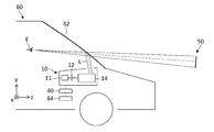
- FIG. 1 is a view schematically showing a configuration of a virtual image display device 10 according to an embodiment.
- the virtual image display device 10 is installed in the dashboard of the vehicle 60, which is an example of a mobile object.
- the virtual image display device 10 is a so-called head-up display device.
- the virtual image display device 10 projects image display light on a windshield 62 which is a virtual image presentation plate, and presents a virtual image 50 in the forward direction of the vehicle 60 (the right direction in FIG. 1).
- a user E such as a driver can visually recognize the virtual image 50 superimposed on the real landscape through the windshield 62. Therefore, the user E can obtain the information shown in the virtual image 50 without moving the sight line while the vehicle is traveling.
- the traveling direction (front-rear direction) of the vehicle 60 is z direction
- the top-bottom direction (vertical direction) of the vehicle 60 is y-direction
- the left-right direction of the vehicle 60 is x-direction.
- the virtual image display device 10 includes an illumination unit 11, a display unit 12, a projection optical system 14, and a control unit 40.
- the illumination unit 11 is a light source for generating display light, and generates illumination light for illuminating the display unit 12.
- the illumination unit 11 includes a light emitting element such as a light emitting diode (LED) or a laser diode (LD), and an optical element for adjusting the intensity distribution and the angular distribution of the output light from the light emitting element.
- the illumination unit 11 provides the display unit 12 with white light of substantially uniform brightness.
- the configuration of the illumination unit 11 is not particularly limited, but in order to adjust the output light from the light emitting element, an optical element such as a light tunnel, a Fresnel lens, or a light diffusion plate can be used, for example.
- the display unit 12 modulates the illumination light from the illumination unit 11 to generate display light, and forms an intermediate image (real image) corresponding to the display content of the virtual image 50.
- the display unit 12 includes a transmissive image display element for generating display light, and includes a display device such as a transmissive liquid crystal panel.
- the image display element receives the image signal transmitted from the control unit 40, and generates image display light of the display content corresponding to the image signal.
- the display unit 12 may further include an optical element for adjusting the direction and light distribution angle of the image display light.
- the display unit 12 may be, for example, a projection unit such as a DMD (Digital Mirror Device) other than a transmissive liquid crystal panel, a LCOS (Liquid Crystal on Silicon), or an LSM (Laser Scanning Module) such as MEMS (Micro Electro Mechanical Systems). It may be configured to be combined with a transmission type screen such as a microlens array sheet or a light diffusion sheet.
- a projection unit such as a DMD (Digital Mirror Device) other than a transmissive liquid crystal panel, a LCOS (Liquid Crystal on Silicon), or an LSM (Laser Scanning Module) such as MEMS (Micro Electro Mechanical Systems).
- a transmission type screen such as a microlens array sheet or a light diffusion sheet.
- the projection optical system 14 projects the image display light generated by the display unit 12 toward the windshield 62.
- the projection optical system 14 includes a transmissive optical element such as a convex lens and a reflective optical element such as a concave mirror. The specific configuration of the projection optical system 14 will be described later separately.
- the control unit 40 generates a display image, and operates the illumination unit 11 and the display unit 12 so that the virtual image 50 corresponding to the display image is presented.
- the control unit 40 is connected to the external device 64, and generates a display image based on the information from the external device 64.
- the external device 64 is a device that generates the original data of the image displayed as the virtual image 50.
- the external device 64 is, for example, an electronic control unit (ECU) of the vehicle 60, a navigation device, a mobile device such as a mobile phone, a smartphone, or a tablet.
- the external device 64 transmits image data necessary for displaying the virtual image 50, information indicating the content and type of the image data, and information on the vehicle 60 such as the speed and current position of the vehicle 60 to the control unit 40.
- ECU electronice control unit
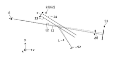
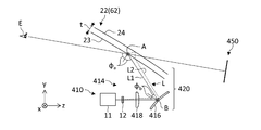
- FIG. 2 is a view schematically showing the generation of a double image caused by the virtual image presentation plate 22.
- an optical element such as a concave mirror disposed between the virtual image presentation plate 22 and the display unit 92 is omitted for simplification of the description.
- the virtual image presenting plate 22 has a predetermined thickness t, and has a first surface 23 and a second surface 24.
- the first surface 23 corresponds to the in-vehicle interface of the windshield 62
- the second surface 24 corresponds to the in-vehicle interface of the windshield 62.
- the image display light L reaching the user E from any one point on the display unit 92 mainly passes through two light paths L1 and L2.
- the first optical path L1 is an optical path reflected by the first surface 23 toward the user E
- the second optical path L2 is refracted by the first surface 23 and reflected by the second surface 24, and then the first surface 23 Is an optical path which is refracted again to the user E.
- an angular difference ⁇ exists between the first optical path L1 and the second optical path L2 directed to the user E
- the image display light passing through each of the two optical paths L1 and L2 is shifted and recognized according to the angular difference ⁇
- a double image occurs in the virtual image 51.
- an optical path toward the user E may be assumed by multiple reflection between the first surface 23 and the second surface 24, the component of the image display light toward the user E toward multiple reflection is small, and in the normal usage mode It can be ignored.
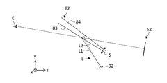
- FIG. 3 is a view schematically showing the suppression of double image by the glazed glass.
- the virtual image presentation board 82 of FIG. 3 is what is called a so-called "glaze glass", and it is comprised so that the thickness of the virtual image presentation board 82 may change according to a place.
- the first surface 83 and the second surface 84 of the virtual image presentation plate 82 have different inclination angles with respect to the line of sight of the user E, and an angle difference ⁇ is provided.
- the angle difference ⁇ is provided between the two surfaces 83 and 84, the angle difference ⁇ between the first light path L1 and the second light path L2 as shown in FIG.
- the suppressed virtual image 52 can be presented.
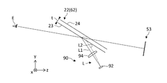
- FIG. 4 is a diagram showing in detail the optical arrangement of the virtual image display device 90 according to the comparative example.
- the comparative example differs from the configuration of FIG. 2 in that a convex lens 94 is provided between the virtual image presentation plate 22 and the display unit 92.
- a convex lens 94 is provided between the virtual image presentation plate 22 and the display unit 92.
- the convex lens 94 by providing the convex lens 94, the first optical path L1 reflected by the first surface 23 of the virtual image presentation plate 22 after starting from any one point of the display unit 92, and the second optical path L1 of the virtual image presentation plate 22 The angular difference between the second light path L2 reflected by the surface 24 can be reduced.
- the double image is eliminated by eliminating the angular difference between the first optical path L1 and the second optical path L2.
- astigmatism may occur when the virtual image presentation plate 22 is formed of a curved surface. Since the windshield 62 of a general automobile is configured by a curved surface and the first surface 23 is configured to be a concave surface, the oblique incidence of the image display light L on the concave surface causes astigmatism.
- the term "astigmatism" as used herein refers to a mismatch between the in-plane focal point and the sagittal in-plane focus of the synthetic optical system.
- the term "meridional plane” refers to a plane including the optical axis of the synthetic optical system and the chief ray of the image display light L, and the yz plane in FIG. 4 corresponds to the meridional plane.
- the “sagittal plane” is a plane including the optical axis of the synthetic optical system and is a plane orthogonal to the meridional plane, and the xz plane in FIG. 4 corresponds to the sagittal plane.
- FIGS. 5A and 5B are diagrams schematically showing astigmatism of a parallel light beam incident on a partial region 98 of the concave surface 96, as viewed from different viewpoints.
- FIG. 5 (a) shows a light flux in the meridional plane (yz plane) of the concave curved surface 96
- FIG. 5 (b) shows a light flux in the sagittal plane (xz flat) of the concave curved surface 96.
- FIG. As illustrated, in the meridional plane and the sagittal plane, the convergence positions Fm and Fs of the parallel light flux are different, and the sagittal in-plane focal point Fs is located farther from the concave surface 96 than the meridional in-plane focal point Fm.
- the focal length of the concave mirror is f and the incident angle of light incident on the concave mirror is ⁇
- the focal length of obliquely incident light is expressed as f ⁇ cos ⁇
- the focal length f ⁇ cos ⁇ decreases as the incident / reflecting angle ⁇ increases.
- the focal length in the meridional plane where the luminous flux is incident obliquely becomes short to f ⁇ cos ⁇ .
- the focal length in the sagittal plane is increased to f / cos ⁇ .
- the projection optical system 14 is configured such that the astigmatism of the entire synthetic optical system including the virtual image presentation plate 22 and the projection optical system 14 is reduced. Specifically, by using one or more features shown in the following (1) to (5), it is possible to achieve both the alleviation of the occurrence of double image and the reduction of astigmatism of the synthetic optical system.
- the concave mirror is disposed at a position twisted with respect to the virtual image presentation plate.
- a projection mirror having a curved surface shape in which the unevenness is opposite to that of the virtual image presentation plate is disposed.
- First Embodiment 6 (a) to 6 (c) are diagrams showing in detail the configuration of the virtual image display device 10 according to the first embodiment, as viewed from different viewpoints.
- FIG. 6 (a) corresponds to FIG. 1 and shows the configuration seen in the yz plane.
- FIG. 6 (b) shows the configuration seen in the xz plane, and
- FIG. 6 (c) shows the configuration seen in the xy plane.
- the present embodiment is a configuration using the above-described feature (1), and the concave mirror 16 included in the projection optical system 14 is disposed at a twisted position with respect to the virtual image presentation plate 22.
- the virtual image display device 10 includes an illumination unit 11, a display unit 12, and a projection optical system 14.
- the projection optical system 14 includes a concave mirror 16 and a convex lens 18.
- the illumination unit 11, the display unit 12, the convex lens 18, and the concave mirror 16 are disposed on the optical axis extending in the x direction.
- the concave mirror 16 reflects the image display light L incident in the x direction toward the virtual image presentation plate 22 in the y direction.
- the virtual image presenting plate 22 reflects the image display light L incident in the y direction toward the user E in the z direction.
- the virtual image presenting plate 22 is configured such that the first surface 23 is a concave surface.
- the first surface 23 of the virtual image presentation plate 22 is a first concave surface on which the image display light L is obliquely incident and reflected.
- the virtual image presentation board 22 is comprised so that thickness t may become fixed, and the curved surface shape of the 1st surface 23 and the 2nd surface 24 is the same.
- the virtual image presentation plate 22 is arranged such that the direction (axis A) orthogonal to both the incident direction and the reflection direction of the image display light L on the first surface 23 (first concave surface) is the x direction.
- the concave mirror 16 is a projection mirror that projects the image display light L toward the virtual image presentation plate 22.
- the convex lens 18 is disposed between the display unit 12 and the concave mirror 16.
- the concave mirror 16 has a second concave surface on which the image display light L enters and reflects obliquely, and the direction (axis B) orthogonal to both the incident direction and the reflection direction of the image display light L on the second concave surface is the z direction It is arranged to become. Therefore, the direction of the axis B of the concave mirror 16 is orthogonal to the direction of the axis A of the virtual image presentation plate 22, and the concave mirror 16 and the virtual image presentation plate 22 are arranged in a twisted manner.
- the virtual image presentation plate 22 and the concave mirror 16 are arranged in a twisted manner, astigmatism generated by the virtual image presentation plate 22 and astigmatism generated by the concave mirror 16 occur in the opposite directions to each other.
- a parallel luminous flux is made incident on the meridional surface (yz plane) of the virtual image presentation plate 22
- the parallel luminous flux is reflected by the virtual image presentation plate 22 and the concave mirror 16 and passes through the convex lens 18, It converges in the xz plane on the optical axis in the x direction.
- the virtual image presentation plate 22 acts to shorten the focal length of the luminous flux in the xz plane and to elongate the focal length of the luminous flux in the xy plane.
- the concave mirror 16 acts to shorten the focal length of the luminous flux in the xy plane and to shorten the focal length of the luminous flux in the xz plane. Therefore, by combining the virtual image presentation plate 22 and the concave mirror 16 in such a twisted arrangement, it is possible to make the astigmatism smaller than in the case where the concave mirror 16 in the twisted arrangement is not provided.
- the amounts of astigmatism generated by the concave mirror 16 and the virtual image presenting plate 22 are equal to each other. You should do it.
- a product f a ⁇ cos [phi a of the cosine cos [phi a of the incident reflection angle phi a of the image display light L at the focal length f a and a concave mirror 1616 of the concave mirror 16, the focal length f b of the virtual image presentation plate 22 it may be such that the product f b ⁇ cos ⁇ b of cosine cos [phi b of the incoming reflection angle phi b of the image display light L in the virtual image presented plate 22 becomes equal.
- the in-plane focal length f a ⁇ cos ⁇ a of the concave mirror 16 is not less than 0.5 times and twice or less the in-plane focal length f b ⁇ cos ⁇ b of the virtual image presentation plate 22 It is possible to preferably prevent a decrease in imaging performance caused by point aberration.
- the display unit 12 at the meridional in-plane focal point of the combining optical system 20 configured by the concave mirror 16, the convex lens 18 and the virtual image presenting plate 22, it is caused by the virtual image presenting plate 22 having two surfaces 23 and 24.
- the occurrence of double image can be eliminated.
- the meridional in-plane focal point of the synthetic optical system 20 refers to the parallel luminous flux when a parallel luminous flux is made incident from the user E toward the virtual image presentation plate 22 along the meridional plane (yz plane) of the virtual image presentation plate 22. It is a condensing position.
- the display unit 12 by arranging the display unit 12 at the in-plane focal point of the combining optical system 20, the occurrence of the double image is alleviated without using a virtual image display plate of a special specification such as a glazed glass. it can. Furthermore, by providing the concave mirror 16 in a torsional arrangement with respect to the virtual image presentation plate 22, it is possible to reduce the amount of astigmatism of the combining optical system 20, and to prevent the deterioration of the imaging performance due to the astigmatism. it can. Thereby, the visibility of the virtual image 50 presented to the user E can be enhanced.
- FIG. 7 is a diagram showing in detail the configuration of the virtual image display device 110 according to the second embodiment.
- the axis A of the virtual image presentation plate 22 and the axis B of the concave mirror 116 are in the same direction (x direction), so that the concave mirror 116 is not in a torsional arrangement with respect to the virtual image presentation plate 22 This is different from the first embodiment.
- the virtual image display device 110 includes an illumination unit 11, a display unit 12 and a projection optical system 114.
- the projection optical system 114 includes a concave mirror 116 and a convex lens 18.
- the concave mirror 116 is a projection mirror having a concave surface on which the image display light L obliquely enters and reflects.
- the illumination unit 11, the display unit 12, the convex lens 18, and the concave mirror 116 are disposed on the optical axis extending in the z direction.
- the concave mirror 116 reflects the image display light L incident in the z direction toward the virtual image presentation plate 22.
- the virtual image presentation plate 22 reflects the image display light L from the concave mirror 116 toward the user E.
- the concave mirror 116 has a curvature in the meridional plane (first cross section) and a sagittal plane (second cross section) in order to reduce the astigmatism amount of the combining optical system 120 including the projection optical system 114 and the virtual image display plate 22.
- the curvature of is configured to be different.
- the meridional surface of the concave mirror 116 is a plane (yz plane) including both the incident direction and the reflection direction of the image display light obliquely incident on the concave mirror 116, and is a plane intersecting the concave surface of the concave mirror 116.
- the sagittal surface of the concave mirror 116 is a plane orthogonal to the meridional surface, and is a plane along the direction (x direction) orthogonal to both the incident direction and the reflection direction of the image display light. It is a crossing plane.
- the curvature in the meridional plane is related to the focal length of the parallel light beam incident along the meridional plane, ie, the meridional in-plane focal length.
- the curvature in the sagittal plane is related to the sagittal in-plane focal length.
- the in-meridional in-plane focal point and the sagittal in-plane focus of the composite optical system 120 coincide with each other.
- the curvature in the meridional plane of the concave mirror 116 smaller than the curvature in the sagittal plane, the difference between the meridional in-plane focal length and the sagittal in-plane focal length can be reduced.
- the specific curvature of the concave mirror 116 is the curvature in the meridional plane and the sagittal plane of the virtual image presentation plate 22, the incident / reflecting angle ⁇ a of the image display light L in the virtual image presentation plate 22, and the incident / reflection of the image display light L in the concave mirror 116 It is preferable to set appropriately according to the value of the angle ⁇ b .
- the amount of astigmatism of the combining optical system 120 is reduced, and the imaging performance due to astigmatism is reduced. Can be prevented.
- the display unit 12 by arranging the display unit 12 at the in-plane focal point of the combining optical system 120, the generation of a double image can be suppressed. Thus, the virtual image 150 with high visibility can be presented to the user.
- this embodiment is applicable also when the 1st surface 23 of the virtual image presentation board 22 is a plane.
- the curvatures in the meridional plane and in the sagittal plane of the concave mirror 116 can be set to different values so that the amount of astigmatism in the concave mirror 116 is reduced. Just do it.
- FIG. 8 is a diagram showing in detail the configuration of the virtual image display device 210 according to the third embodiment.
- the present embodiment is different from the above-described embodiment in that a parallel flat plate 219 obliquely disposed between the display unit 12 and the convex lens 218 is added.
- the virtual image display device 210 includes the illumination unit 11, the display unit 12, and the projection optical system 214.
- the projection optical system 214 includes a concave mirror 216, a convex lens 218 and a plane parallel plate 219.
- the illumination unit 11, the display unit 12, the parallel flat plate 219, the convex lens 218, and the concave mirror 216 are disposed on the optical axis extending in the z direction.
- the parallel flat plate 219 is a transparent member having a uniform thickness, and is made of glass or a resin material.
- the parallel flat plate 219 is disposed obliquely to the light path of the projection optical system 214, and is disposed such that the rotation axis C is in the direction (x direction) orthogonal to the meridional plane (yz plane).
- the focal length of the combining optical system 220 configured by the virtual image presenting plate 22 and the projection optical system 214 becomes long.
- the meridional in-plane focal length can be made longer than the sagittal in-plane focal length.
- the difference between the meridional in-plane focal length and the sagittal in-plane focal length can be reduced, and astigmatism can be alleviated, as compared to the case where the parallel flat plate 219 is not inserted.
- the amount of increase in focal length due to the parallel flat plate 219 depends on the tilt angle ⁇ c of the parallel flat plate 219, so the amount of astigmatism can be adjusted by changing the tilt angle ⁇ c .
- the amount of astigmatism of the combining optical system 220 can be reduced by inserting the parallel flat plate 219. Furthermore, by arranging the display unit 12 at the in-plane focal point of the combining optical system 220, the generation of double images can be suppressed. Thereby, the visibility of the virtual image 250 can be improved.
- FIGS. 9A and 9B are diagrams showing in detail the configuration of the virtual image display device 310 according to the fourth embodiment, as viewed from different viewpoints.
- FIG. 9 (a) corresponds to FIG. 1 and shows the configuration seen in the yz plane
- FIG. 9 (b) shows the configuration seen in the xz plane.
- the present embodiment is different from the above-described embodiment in that the projection optical system 314 includes two concave mirrors 316 and 318, and the two concave mirrors 316 and 318 are in a twisting arrangement.
- the virtual image display device 310 includes the illumination unit 11, the display unit 12, and the projection optical system 314.
- the projection optical system 314 includes a first concave mirror 316 and a second concave mirror 318.
- the illumination unit 11, the display unit 12, and the second concave mirror 318 are disposed on the optical axis extending in the x direction.
- the second concave mirror 318 is disposed so that the direction (axis D) orthogonal to both the incident direction and the reflection direction of the image display light L is the y direction, and the image display light L incident in the x direction is the z direction Reflect on
- the first concave mirror 316 is disposed so that the direction (axis B) orthogonal to both the incident direction and the reflection direction of the image display light L is the x direction, and the virtual image presentation plate 22 receives the image display light L incident in the z direction. Reflect towards.
- the first concave mirror 316 and the second concave mirror 318 are arranged in a twisting manner, astigmatism produced by the respective concave mirrors can be made opposite to each other.
- the mechanism for combining two concave surfaces to reduce astigmatism is the same as that of the first embodiment described above. Therefore, also in the present embodiment, it is possible to reduce the amount of astigmatism of the combining optical system 320 configured by the virtual image presentation plate 22 and the projection optical system 314, and to improve the imaging performance. Furthermore, by arranging the display unit 12 at the in-plane focal point of the combining optical system 320, generation of a double image can be suppressed. Thereby, the visibility of the virtual image 350 can be improved.
- this embodiment is applicable also when the 1st surface 23 of the virtual image presentation board 22 is a plane.
- the curvatures of the two concave mirrors 316 and 318 and the respective curvatures of the two concave mirrors 316 and 318 can be reduced so that the amount of astigmatism of the combination of the first concave mirror 316 and the second concave mirror 318 is reduced.
- the incident and reflection angles ⁇ b and ⁇ d may be set.
- the projection optical system 314 is not provided with a convex lens, but an additional convex lens may be provided in the projection optical system 314.
- an additional convex lens may be disposed between the display unit 12 and the second concave mirror 318, and an additional convex lens may be disposed between the second concave mirror 318 and the first concave mirror 316.
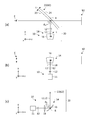
- FIG. 10 is a diagram showing in detail the configuration of the virtual image display device 410 according to the fifth embodiment.
- the present embodiment is different from the above-described embodiment in that a convex mirror 416 is used to reduce astigmatism generated in the virtual image display plate 22. That is, by inverting the concavo-convex shapes of the virtual image presentation plate 22 and the projection mirror, astigmatism generated on each of the curved surfaces is produced in the opposite direction, and the amount of astigmatism of the entire synthetic optical system is reduced.
- the virtual image display device 410 includes the illumination unit 11, the display unit 12, and the projection optical system 414.
- the projection optical system 414 includes a convex mirror 416 and a convex lens 418.
- the illumination unit 11, the display unit 12, the convex lens 418, and the convex mirror 416 are disposed on the optical axis extending in the z direction.
- the convex mirror 416 is a projection mirror whose incident / reflection surface of the image display light L is a convex curved surface.
- the convex mirror 416 is disposed so that the direction (axis B) orthogonal to both the incident direction and the reflection direction of the image display light L is the x direction, and the virtual image presentation plate 22 receives the image display light L incident in the z direction. Reflect towards.
- the virtual image presentation plate 22 is configured such that the first surface 23 on which the image display light L is reflected is a concave surface, and the direction (axis A) orthogonal to both the incident direction and the reflection direction of the image display light L is It is arranged to be in the x direction.
- the virtual image presentation plate 22 reflects the image display light L from the convex mirror 416 toward the user E.
- the virtual image presentation plate 22 and the convex mirror 416 are arranged to face each other, and since the concaves and convexes of the respective curved surfaces are opposite to each other, the astigmatism amount generated on the respective curved surfaces is reduced or canceled. be able to.
- the amount of astigmatism of the combining optical system 420 including the virtual image presentation plate 22 and the projection optical system 414 can be reduced to enhance the imaging performance.
- the display unit 12 at the in-plane focal point of the combining optical system 420, the generation of a double image can be suppressed. Therefore, according to the present embodiment, it is possible to reduce both the astigmatic main difference and the double image, and to improve the visibility of the virtual image 450 presented to the user E.
- the present invention was explained with reference to the above-mentioned embodiment, the present invention is not limited to the above-mentioned embodiment, but what was suitably combined and replaced with composition shown in each display example. Are also included in the present invention.
- the case where the astigmatism of the synthetic optical system is alleviated by using any one of the above-mentioned features (1) to (5) is shown.
- a plurality of features may be used in combination.
- the feature (2) or the feature (3) may be combined with the feature (1)
- the feature (3) or the feature (4) may be combined with the feature (2)
- the feature (4) or the feature (5) may be combined with the feature (3).
- the 1st field 23 of virtual image presentation board 22 is constituted by a concave curve or a plane.
- the synthetic optical system may be configured to alleviate the astigmatism.
- the concave mirror 16 may be replaced by a convex mirror.
- the curvature in the meridional plane may be larger than the curvature in the sagittal plane.
- the convex mirror 416 may be replaced by a concave mirror.
- the projection optical system may not be provided with a convex lens.
- the projection optical system 14 may not include the convex lens 18, and the meridional in-plane focal point of the synthetic optical system 20 not including the convex lens 18 may be provided.
- the display unit 12 may be disposed on the Similarly, in the embodiment shown in FIG. 7, the projection optical system 114 may not include the convex lens 18, and in the embodiment shown in FIG. 8, the projection optical system 214 may not include the convex lens 218. It is also good.
- a virtual image display apparatus for presenting a virtual image to a user via a virtual image presentation board, comprising: A display unit that generates image display light; And a projection optical system including a projection mirror that projects the image display light toward the virtual image presentation plate so that the image display light is obliquely reflected by the first concave surface of the virtual image presentation plate,
- the projection mirror has a second concave surface on which the image display light obliquely enters and reflects, and a direction orthogonal to both the incident direction and the reflection direction of the image display light on the first concave surface, and the second It is disposed such that the direction orthogonal to both the incident direction and the reflection direction of the image display light on the concave surface is orthogonal to each other,
- the display unit is disposed at a meridional in-plane focal point of a synthetic optical system configured of the virtual image presentation plate and the projection optical system, and a meridional in-plane focal point of the synthetic optical system
- the projection mirror is configured such that the curvature at a second cross section intersecting the second concave curved surface is larger than the curvature at a first cross section intersecting the second concave curved surface, and the first cross section
- the second cross section is a plane including both the incident direction and the reflection direction of the image display light obliquely incident on the second concave surface
- the second cross section is a plane orthogonal to the first cross section, and is oblique to the second concave surface.
- the virtual image display device according to Item 1-1 which is a plane along a direction orthogonal to both the incident direction and the reflection direction of the incident image display light.
- a virtual image display apparatus for presenting a virtual image to a user via a virtual image presentation board, comprising: A display unit that generates image display light; A projection optical system including a projection mirror for projecting the image display light toward the virtual image presentation plate; The projection mirror has a concave surface on which the image display light obliquely enters and reflects, and the curvature in the second cross section intersecting with the concave surface is larger than the curvature in the first cross section intersecting with the concave surface.
- the first cross section is a plane including both the incident direction and the reflection direction of the image display light obliquely incident on the concave surface
- the second cross section is a plane orthogonal to the first cross section.
- the display unit is disposed at a meridional in-plane focal point of a synthetic optical system configured by the virtual image presentation plate and the projection optical system.
- the meridional in-plane focal point of the synthetic optical system is a condensing position of the parallel light beam when the parallel light beam is made incident from the user toward the virtual image display plate along the meridional surface of the virtual image display plate
- a virtual image display device characterized by (Section 2-2) The virtual image display device according to Item 2-1, wherein the projection optical system further includes a parallel flat plate disposed obliquely to the light path of the projection optical system.
- a virtual image display apparatus for presenting a virtual image to a user via a virtual image presentation board, comprising: A display unit that generates image display light; A projection optical system for projecting the image display light toward the virtual image presentation plate; The projection optical system includes a projection mirror that projects the image display light toward the virtual image display plate, and a parallel flat plate disposed obliquely to the light path of the projection optical system.
- the display unit is disposed at a meridional in-plane focal point of a synthetic optical system configured by the virtual image presentation plate and the projection optical system.
- the meridional in-plane focal point of the synthetic optical system is a condensing position of the parallel light beam when the parallel light beam is made incident from the user toward the virtual image display plate along the meridional surface of the virtual image display plate
- a virtual image display device characterized by
- a virtual image display apparatus for presenting a virtual image to a user via a virtual image presentation board, comprising: A display unit that generates image display light; A projection optical system for projecting the image display light toward the virtual image presentation plate; The projection optical system includes a first concave mirror that reflects the image display light toward the virtual image presentation plate, and a second concave mirror that reflects the image display light toward the first concave mirror.
- the first concave mirror is configured to move the image display light in the direction along the reference plane.
- the second concave mirror is disposed to be incident, and the second concave mirror is disposed to be incident to the second concave mirror in a direction in which the image display light intersects the reference surface.
- the display unit is disposed at a meridional in-plane focal point of a synthetic optical system configured of the virtual image presentation plate and the projection optical system, and a meridional in-plane focal point of the synthetic optical system is along the meridional plane of the virtual image presentation plate
- a virtual image display apparatus characterized in that it is a condensing position of the parallel beam when the parallel beam is incident from the user toward the virtual image display plate.
- the curved surface of at least one of the first concave mirror and the second concave mirror is configured such that the curvature of the second cross section intersecting the curved surface is larger than the curvature of the first cross section intersecting the curved surface
- the first cross section is a plane including both the incident direction and the reflection direction of the image display light obliquely incident on the curved surface
- the second cross section is a plane orthogonal to the first cross section and the curved surface
- the virtual image display device according to Item 4-1 which is a plane along a direction orthogonal to both the incident direction and the reflection direction of the image display light that is obliquely incident.
- the projection optical system further includes a parallel flat plate disposed obliquely to the light path of the projection optical system.
- a virtual image display apparatus for presenting a virtual image to a user via a virtual image presentation board, comprising: A display unit that generates image display light; And a projection optical system including a projection mirror that projects the image display light toward the virtual image presentation plate so that the image display light is obliquely reflected by the concave curved surface of the virtual image presentation plate,
- the projection mirror has a convex surface on which the image display light obliquely enters and reflects, and a direction orthogonal to both the incident direction and the reflection direction of the image display light on the concave surface, and the image display on the convex surface Are arranged so that the directions orthogonal to both the incident direction and the reflection direction of light are parallel to each other,
- the display unit is disposed at a meridional in-plane focal point of a synthetic optical system configured of the virtual image presentation plate and the projection optical system, and a meridional in-plane focal point of the synthetic optical system is along the meridional plane of the virtual image presentation plate A
- E user
- L image display light
- 10 virtual image display device
- 12 display unit
- 14 projection optical system
- 16 concave mirror (projection mirror)
- 20 synthetic optical system
- 22 virtual image presentation plate
- the visibility of a virtual image can be improved by reducing the generation of a double image.
Landscapes
- Physics & Mathematics (AREA)
- Engineering & Computer Science (AREA)
- General Physics & Mathematics (AREA)
- Optics & Photonics (AREA)
- Chemical & Material Sciences (AREA)
- Combustion & Propulsion (AREA)
- Transportation (AREA)
- Mechanical Engineering (AREA)
- Multimedia (AREA)
- Signal Processing (AREA)
- Instrument Panels (AREA)
- Transforming Electric Information Into Light Information (AREA)
Abstract
Description
(1)虚像提示板に対してねじれた位置に凹面鏡を配置する。
(2)サジタル方向とメリディオナル方向の曲率が異なる投射鏡を配置する。
(3)光軸に対して傾斜させた平行平板を挿入する。
(4)互いにねじれた位置となる二枚の凹面鏡を組み合わせる。
(5)虚像提示板とは凹凸が逆となる曲面形状の投射鏡を配置する。
図6(a)~(c)は、第1の実施の形態に係る虚像表示装置10の構成を詳細に示す図であり、それぞれ異なる視点から見た図である。図6(a)は、図1に対応し、yz平面で見た構成を示す。図6(b)は、xz平面で見た構成を示し、図6(c)は、xy平面で見た構成を示す。本実施の形態は、上述の特徴(1)を用いた構成であり、虚像提示板22に対し、投射光学系14に含まれる凹面鏡16がねじれた位置に配置されている。
図7は、第2の実施の形態に係る虚像表示装置110の構成を詳細に示す図である。本実施の形態は、虚像提示板22の軸Aと凹面鏡116の軸Bが同じ方向(x方向)となっており、虚像提示板22に対して凹面鏡116がねじれ配置ではない点で上述の第1の実施の形態と相違する。
図8は、第3の実施の形態に係る虚像表示装置210の構成を詳細に示す図である。本実施の形態は、表示部12と凸レンズ218の間に斜めに配置される平行平板219が追加される点で上述の実施の形態と相違する。
図9(a),(b)は、第4の実施の形態に係る虚像表示装置310の構成を詳細に示す図であり、それぞれ異なる視点から見た図である。図9(a)は、図1に対応し、yz平面で見た構成を示し、図9(b)は、xz平面で見た構成を示す。本実施の形態は、投射光学系314が二枚の凹面鏡316,318を含み、二枚の凹面鏡316,318がねじれ配置となる点で上述の実施の形態と相違する。
図10は、第5の実施の形態に係る虚像表示装置410の構成を詳細に示す図である。本実施の形態は、虚像提示板22にて生じる非点収差を緩和させるため、凸面鏡416を用いる点で上述の実施の形態と相違する。つまり、虚像提示板22と投射鏡の凹凸形状を逆にすることで、それぞれの曲面で生じる非点収差を逆向きに生じさせ、合成光学系全体の非点収差量を小さくする。
(項1-1)
虚像提示板を介してユーザに虚像を提示するための虚像表示装置であって、
画像表示光を生成する表示部と、
前記虚像提示板の第1凹曲面にて前記画像表示光が斜めに入反射するように前記画像表示光を前記虚像提示板に向けて投射する投射鏡を含む投射光学系と、を備え、
前記投射鏡は、前記画像表示光が斜めに入反射する第2凹曲面を有し、前記第1凹曲面における前記画像表示光の入射方向と反射方向の双方に直交する方向と、前記第2凹曲面における前記画像表示光の入射方向と反射方向の双方に直交する方向とが互いに直交するように配置され、
前記表示部は、前記虚像提示板および前記投射光学系により構成される合成光学系のメリディオナル面内焦点に配置され、前記合成光学系のメリディオナル面内焦点は、前記虚像提示板のメリディオナル面に沿って前記ユーザから前記虚像提示板に向けて平行光束を入射させたときの当該平行光束の集光位置であることを特徴とする虚像表示装置。
(項1-2)
前記投射鏡は、前記第2凹曲面と交差する第1断面での曲率よりも前記第2凹曲面と交差する第2断面での曲率が大きくなるように構成され、前記第1断面は、前記第2凹曲面に斜入射する画像表示光の入射方向と反射方向の双方を含む平面であり、前記第2断面は、前記第1断面に直交する平面であって、前記第2凹曲面に斜入射する画像表示光の入射方向と反射方向の双方に直交する方向に沿う平面であることを特徴とする項1-1に記載の虚像表示装置。
(項1-3)
前記投射光学系は、前記投射光学系の光路に対して斜めに配置される平行平板をさらに含むことを特徴とする項1-1または項1-2に記載の虚像表示装置。
虚像提示板を介してユーザに虚像を提示するための虚像表示装置であって、
画像表示光を生成する表示部と、
前記画像表示光を前記虚像提示板に向けて投射する投射鏡を含む投射光学系と、を備え、
前記投射鏡は、前記画像表示光が斜めに入反射する凹曲面を有し、前記凹曲面と交差する第1断面での曲率よりも前記凹曲面と交差する第2断面での曲率が大きくなるように構成され、前記第1断面は、前記凹曲面に斜入射する画像表示光の入射方向と反射方向の双方を含む平面であり、前記第2断面は、前記第1断面に直交する平面であって、前記凹曲面に斜入射する画像表示光の入射方向と反射方向の双方に直交する方向に沿う平面であり、
前記表示部は、前記虚像提示板および前記投射光学系により構成される合成光学系のメリディオナル面内焦点に配置され、
前記合成光学系のメリディオナル面内焦点は、前記虚像提示板のメリディオナル面に沿って前記ユーザから前記虚像提示板に向けて平行光束を入射させたときの当該平行光束の集光位置であることを特徴とする虚像表示装置。
(項2-2)
前記投射光学系は、前記投射光学系の光路に対して斜めに配置される平行平板をさらに含むことを特徴とする項2-1に記載の虚像表示装置。
虚像提示板を介してユーザに虚像を提示するための虚像表示装置であって、
画像表示光を生成する表示部と、
前記画像表示光を前記虚像提示板に向けて投射する投射光学系と、を備え、
前記投射光学系は、前記虚像提示板に向けて前記画像表示光を投射する投射鏡と、前記投射光学系の光路に対して斜めに配置される平行平板と、を含み、
前記表示部は、前記虚像提示板および前記投射光学系により構成される合成光学系のメリディオナル面内焦点に配置され、
前記合成光学系のメリディオナル面内焦点は、前記虚像提示板のメリディオナル面に沿って前記ユーザから前記虚像提示板に向けて平行光束を入射させたときの当該平行光束の集光位置であることを特徴とする虚像表示装置。
虚像提示板を介してユーザに虚像を提示するための虚像表示装置であって、
画像表示光を生成する表示部と、
前記画像表示光を前記虚像提示板に向けて投射する投射光学系と、を備え、
前記投射光学系は、前記画像表示光を前記虚像提示板に向けて反射させる第1凹面鏡と、前記画像表示光を前記第1凹面鏡に向けて反射させる第2凹面鏡と、を含み、
前記虚像提示板における前記画像表示光の入射方向と出射方向の双方に沿う平面を基準面としたとき、前記第1凹面鏡は、前記画像表示光が前記基準面に沿う方向に前記第1凹面鏡に入射する向きとなるよう配置され、前記第2凹面鏡は、前記画像表示光が前記基準面に交差する方向に前記第2凹面鏡に入射する向きとなるよう配置され、
前記表示部は、前記虚像提示板および前記投射光学系により構成される合成光学系のメリディオナル面内焦点に配置され、前記合成光学系のメリディオナル面内焦点は、前記虚像提示板のメリディオナル面に沿って前記ユーザから前記虚像提示板に向けて平行光束を入射させたときの当該平行光束の集光位置であることを特徴とする虚像表示装置。
(項4-2)
前記第1凹面鏡および前記第2凹面鏡の少なくとも一方の曲面は、当該曲面と交差する第1断面での曲率よりも当該曲面と交差する第2断面での曲率が大きくなるように構成されており、前記第1断面は、当該曲面に斜入射する画像表示光の入射方向と反射方向の双方を含む平面であり、前記第2断面は、前記第1断面に直交する平面であって、当該曲面に斜入射する画像表示光の入射方向と反射方向の双方に直交する方向に沿う平面であることを特徴とする項4-1に記載の虚像表示装置。
(項4-3)
前記投射光学系は、前記投射光学系の光路に対して斜めに配置される平行平板をさらに含むことを特徴とする項4-2に記載の虚像表示装置。
虚像提示板を介してユーザに虚像を提示するための虚像表示装置であって、
画像表示光を生成する表示部と、
前記虚像提示板の凹曲面にて前記画像表示光が斜めに入反射するように前記画像表示光を前記虚像提示板に向けて投射する投射鏡を含む投射光学系と、を備え、
前記投射鏡は、前記画像表示光が斜めに入反射する凸曲面を有し、前記凹曲面における前記画像表示光の入射方向と反射方向の双方に直交する方向と、前記凸曲面における前記画像表示光の入射方向と反射方向の双方に直交する方向とが互いに平行となるように配置され、
前記表示部は、前記虚像提示板および前記投射光学系により構成される合成光学系のメリディオナル面内焦点に配置され、前記合成光学系のメリディオナル面内焦点は、前記虚像提示板のメリディオナル面に沿って前記ユーザから前記虚像提示板に向けて平行光束を入射させたときの当該平行光束の集光位置であることを特徴とする虚像表示装置。
(項5-2)
前記投射光学系は、前記投射光学系の光路に対して斜めに配置される平行平板をさらに含むことを特徴とする項5-1に記載の虚像表示装置。
Claims (3)
- 虚像提示板を介してユーザに虚像を提示するための虚像表示装置であって、
画像表示光を生成する表示部と、
前記画像表示光を前記虚像提示板に向けて投射する投射鏡を含む投射光学系と、を備え、
前記投射鏡は、前記画像表示光が斜めに入反射する凹曲面を有し、前記凹曲面と交差する第1断面での曲率よりも前記凹曲面と交差する第2断面での曲率が大きくなるように構成され、前記第1断面は、前記凹曲面に斜入射する画像表示光の入射方向と反射方向の双方を含む平面であり、前記第2断面は、前記第1断面に直交する平面であって、前記凹曲面に斜入射する画像表示光の入射方向と反射方向の双方に直交する方向に沿う平面であり、
前記表示部は、前記虚像提示板および前記投射光学系により構成される合成光学系のメリディオナル面内焦点に配置され、
前記合成光学系のメリディオナル面内焦点は、前記虚像提示板のメリディオナル面に沿って前記ユーザから前記虚像提示板に向けて平行光束を入射させたときの当該平行光束の集光位置であることを特徴とする虚像表示装置。 - 前記投射光学系は、前記投射光学系の光路に対して斜めに配置される平行平板をさらに含むことを特徴とする請求項1に記載の虚像表示装置。
- 前記虚像提示板は、車両に設けられる厚さが均一なウインドシールドであることを特徴とする請求項1または2に記載の虚像表示装置。
Priority Applications (4)
| Application Number | Priority Date | Filing Date | Title |
|---|---|---|---|
| KR1020197029695A KR102077633B1 (ko) | 2018-01-12 | 2018-10-15 | 허상 표시 장치 |
| CN201880012533.8A CN110300915B (zh) | 2018-01-12 | 2018-10-15 | 虚像显示装置 |
| EP18899373.7A EP3611554B1 (en) | 2018-01-12 | 2018-10-15 | Virtual image display device |
| US16/656,610 US11353713B2 (en) | 2018-01-12 | 2019-10-18 | Virtual image display device |
Applications Claiming Priority (2)
| Application Number | Priority Date | Filing Date | Title |
|---|---|---|---|
| JP2018-003135 | 2018-01-12 | ||
| JP2018003135A JP6593462B2 (ja) | 2018-01-12 | 2018-01-12 | 虚像表示装置 |
Related Child Applications (1)
| Application Number | Title | Priority Date | Filing Date |
|---|---|---|---|
| US16/656,610 Continuation US11353713B2 (en) | 2018-01-12 | 2019-10-18 | Virtual image display device |
Publications (1)
| Publication Number | Publication Date |
|---|---|
| WO2019138626A1 true WO2019138626A1 (ja) | 2019-07-18 |
Family
ID=67218244
Family Applications (1)
| Application Number | Title | Priority Date | Filing Date |
|---|---|---|---|
| PCT/JP2018/038343 Ceased WO2019138626A1 (ja) | 2018-01-12 | 2018-10-15 | 虚像表示装置 |
Country Status (6)
| Country | Link |
|---|---|
| US (1) | US11353713B2 (ja) |
| EP (1) | EP3611554B1 (ja) |
| JP (1) | JP6593462B2 (ja) |
| KR (1) | KR102077633B1 (ja) |
| CN (1) | CN110300915B (ja) |
| WO (1) | WO2019138626A1 (ja) |
Families Citing this family (4)
| Publication number | Priority date | Publication date | Assignee | Title |
|---|---|---|---|---|
| KR102077635B1 (ko) * | 2018-01-12 | 2020-02-14 | 가부시키가이샤 제이브이씨 켄우드 | 허상 표시 장치 |
| JP6593465B2 (ja) * | 2018-01-12 | 2019-10-23 | 株式会社Jvcケンウッド | 虚像表示装置 |
| JP7122673B2 (ja) | 2018-06-29 | 2022-08-22 | パナソニックIpマネジメント株式会社 | 表示器、表示システム、移動体 |
| CN112731667A (zh) * | 2021-01-05 | 2021-04-30 | 业成科技(成都)有限公司 | 投影装置及投影方法 |
Citations (5)
| Publication number | Priority date | Publication date | Assignee | Title |
|---|---|---|---|---|
| JPS62225429A (ja) | 1986-03-28 | 1987-10-03 | Yazaki Corp | 車載用ヘツドアツプデイスプレイ装置 |
| JPH03209210A (ja) * | 1989-09-28 | 1991-09-12 | Hughes Aircraft Co | ヘッドアップデイスプレイ、楔形フロントガラス及び楔形フロントガラスの組立方法 |
| JP2005156678A (ja) * | 2003-11-21 | 2005-06-16 | Nippon Seiki Co Ltd | コンバイナおよびそのコンバイナを用いたヘッドアップディスプレイ |
| JP2012058688A (ja) * | 2010-09-13 | 2012-03-22 | Yazaki Corp | ヘッドアップディスプレイ |
| WO2017187514A1 (ja) * | 2016-04-26 | 2017-11-02 | 日立マクセル株式会社 | 情報表示装置 |
Family Cites Families (15)
| Publication number | Priority date | Publication date | Assignee | Title |
|---|---|---|---|---|
| US4787711A (en) * | 1986-01-23 | 1988-11-29 | Yazaki Corporation | On-vehicle head up display device with optical means for correcting parallax in a vertical direction |
| JPH0628993B2 (ja) * | 1986-05-23 | 1994-04-20 | 日産自動車株式会社 | 車両用表示装置 |
| EP0631167B1 (en) * | 1992-12-14 | 2005-02-16 | Denso Corporation | Image display |
| EP0602732A3 (en) * | 1992-12-17 | 1995-09-27 | Philips Electronics Nv | Optical system with astigmatism compensation. |
| JP3856501B2 (ja) | 1995-09-07 | 2006-12-13 | 松下電器産業株式会社 | 光学装置、光学補正方法及び投写型表示装置 |
| JPH1164779A (ja) * | 1997-08-08 | 1999-03-05 | Shimadzu Corp | 自動車用ヘッドアップディスプレイ |
| JP5125147B2 (ja) * | 2007-02-27 | 2013-01-23 | 株式会社日立製作所 | 投射型表示装置 |
| JP2009122582A (ja) | 2007-11-19 | 2009-06-04 | Fujinon Corp | 投影光学系及びヘッドアップディスプレイ装置 |
| JP2009136551A (ja) * | 2007-12-07 | 2009-06-25 | Denso Corp | 車両用顔特徴量検出装置及び顔特徴量検出方法 |
| US20090231720A1 (en) * | 2008-03-12 | 2009-09-17 | Chengalva Mahesh K | Heads up display |
| CN102656501B (zh) * | 2009-12-14 | 2014-07-02 | 松下电器产业株式会社 | 透过型显示装置 |
| US8724225B2 (en) * | 2011-01-26 | 2014-05-13 | Korea Institute Of Construction Technology | Optical system for use in a vehicle head-up display |
| JP6000554B2 (ja) * | 2012-01-24 | 2016-09-28 | オリンパス株式会社 | 顕微鏡システム |
| JP2015045808A (ja) * | 2013-08-29 | 2015-03-12 | 日本精機株式会社 | ヘッドアップディスプレイ装置 |
| JP6432540B2 (ja) * | 2016-02-16 | 2018-12-05 | 株式会社デンソー | ヘッドアップディスプレイ装置 |
-
2018
- 2018-01-12 JP JP2018003135A patent/JP6593462B2/ja active Active
- 2018-10-15 WO PCT/JP2018/038343 patent/WO2019138626A1/ja not_active Ceased
- 2018-10-15 KR KR1020197029695A patent/KR102077633B1/ko active Active
- 2018-10-15 EP EP18899373.7A patent/EP3611554B1/en active Active
- 2018-10-15 CN CN201880012533.8A patent/CN110300915B/zh active Active
-
2019
- 2019-10-18 US US16/656,610 patent/US11353713B2/en active Active
Patent Citations (5)
| Publication number | Priority date | Publication date | Assignee | Title |
|---|---|---|---|---|
| JPS62225429A (ja) | 1986-03-28 | 1987-10-03 | Yazaki Corp | 車載用ヘツドアツプデイスプレイ装置 |
| JPH03209210A (ja) * | 1989-09-28 | 1991-09-12 | Hughes Aircraft Co | ヘッドアップデイスプレイ、楔形フロントガラス及び楔形フロントガラスの組立方法 |
| JP2005156678A (ja) * | 2003-11-21 | 2005-06-16 | Nippon Seiki Co Ltd | コンバイナおよびそのコンバイナを用いたヘッドアップディスプレイ |
| JP2012058688A (ja) * | 2010-09-13 | 2012-03-22 | Yazaki Corp | ヘッドアップディスプレイ |
| WO2017187514A1 (ja) * | 2016-04-26 | 2017-11-02 | 日立マクセル株式会社 | 情報表示装置 |
Non-Patent Citations (1)
| Title |
|---|
| See also references of EP3611554A4 |
Also Published As
| Publication number | Publication date |
|---|---|
| KR102077633B1 (ko) | 2020-02-14 |
| US20200050006A1 (en) | 2020-02-13 |
| EP3611554A1 (en) | 2020-02-19 |
| EP3611554B1 (en) | 2025-08-27 |
| JP2019124728A (ja) | 2019-07-25 |
| CN110300915B (zh) | 2020-04-28 |
| JP6593462B2 (ja) | 2019-10-23 |
| EP3611554A4 (en) | 2020-07-01 |
| CN110300915A (zh) | 2019-10-01 |
| US11353713B2 (en) | 2022-06-07 |
| KR20190118682A (ko) | 2019-10-18 |
Similar Documents
| Publication | Publication Date | Title |
|---|---|---|
| CN110073275B (zh) | 虚像显示装置 | |
| WO2019003514A1 (ja) | 虚像表示装置 | |
| US11131851B2 (en) | Virtual image display device | |
| US11353713B2 (en) | Virtual image display device | |
| KR102077635B1 (ko) | 허상 표시 장치 | |
| US11300796B2 (en) | Virtual image display device | |
| US11119317B2 (en) | Virtual image display device | |
| WO2019012739A1 (ja) | 虚像表示装置 | |
| JP2020073963A (ja) | 虚像表示装置 | |
| JP6593463B2 (ja) | 虚像表示装置 | |
| JP6593494B1 (ja) | 虚像表示装置 | |
| JP2020016897A (ja) | 虚像表示装置 |
Legal Events
| Date | Code | Title | Description |
|---|---|---|---|
| 121 | Ep: the epo has been informed by wipo that ep was designated in this application |
Ref document number: 18899373 Country of ref document: EP Kind code of ref document: A1 |
|
| ENP | Entry into the national phase |
Ref document number: 20197029695 Country of ref document: KR Kind code of ref document: A |
|
| ENP | Entry into the national phase |
Ref document number: 2018899373 Country of ref document: EP Effective date: 20191031 |
|
| NENP | Non-entry into the national phase |
Ref country code: DE |
|
| WWG | Wipo information: grant in national office |
Ref document number: 2018899373 Country of ref document: EP |