WO2019138633A1 - 生体情報取得装置、生体情報取得方法及びウェアラブルデバイス - Google Patents
生体情報取得装置、生体情報取得方法及びウェアラブルデバイス Download PDFInfo
- Publication number
- WO2019138633A1 WO2019138633A1 PCT/JP2018/038583 JP2018038583W WO2019138633A1 WO 2019138633 A1 WO2019138633 A1 WO 2019138633A1 JP 2018038583 W JP2018038583 W JP 2018038583W WO 2019138633 A1 WO2019138633 A1 WO 2019138633A1
- Authority
- WO
- WIPO (PCT)
- Prior art keywords
- light
- biological information
- image sensor
- living body
- lens
- Prior art date
- Legal status (The legal status is an assumption and is not a legal conclusion. Google has not performed a legal analysis and makes no representation as to the accuracy of the status listed.)
- Ceased
Links
Images


Classifications
-
- A—HUMAN NECESSITIES
- A61—MEDICAL OR VETERINARY SCIENCE; HYGIENE
- A61B—DIAGNOSIS; SURGERY; IDENTIFICATION
- A61B5/00—Measuring for diagnostic purposes; Identification of persons
- A61B5/02—Detecting, measuring or recording for evaluating the cardiovascular system, e.g. pulse, heart rate, blood pressure or blood flow
- A61B5/026—Measuring blood flow
-
- A—HUMAN NECESSITIES
- A61—MEDICAL OR VETERINARY SCIENCE; HYGIENE
- A61B—DIAGNOSIS; SURGERY; IDENTIFICATION
- A61B5/00—Measuring for diagnostic purposes; Identification of persons
- A61B5/0059—Measuring for diagnostic purposes; Identification of persons using light, e.g. diagnosis by transillumination, diascopy, fluorescence
- A61B5/0077—Devices for viewing the surface of the body, e.g. camera, magnifying lens
-
- A—HUMAN NECESSITIES
- A61—MEDICAL OR VETERINARY SCIENCE; HYGIENE
- A61B—DIAGNOSIS; SURGERY; IDENTIFICATION
- A61B5/00—Measuring for diagnostic purposes; Identification of persons
- A61B5/0059—Measuring for diagnostic purposes; Identification of persons using light, e.g. diagnosis by transillumination, diascopy, fluorescence
- A61B5/0082—Measuring for diagnostic purposes; Identification of persons using light, e.g. diagnosis by transillumination, diascopy, fluorescence adapted for particular medical purposes
-
- A—HUMAN NECESSITIES
- A61—MEDICAL OR VETERINARY SCIENCE; HYGIENE
- A61B—DIAGNOSIS; SURGERY; IDENTIFICATION
- A61B5/00—Measuring for diagnostic purposes; Identification of persons
- A61B5/02—Detecting, measuring or recording for evaluating the cardiovascular system, e.g. pulse, heart rate, blood pressure or blood flow
- A61B5/021—Measuring pressure in heart or blood vessels
- A61B5/02108—Measuring pressure in heart or blood vessels from analysis of pulse wave characteristics
-
- A—HUMAN NECESSITIES
- A61—MEDICAL OR VETERINARY SCIENCE; HYGIENE
- A61B—DIAGNOSIS; SURGERY; IDENTIFICATION
- A61B5/00—Measuring for diagnostic purposes; Identification of persons
- A61B5/68—Arrangements of detecting, measuring or recording means, e.g. sensors, in relation to patient
- A61B5/6801—Arrangements of detecting, measuring or recording means, e.g. sensors, in relation to patient specially adapted to be attached to or worn on the body surface
-
- G—PHYSICS
- G06—COMPUTING OR CALCULATING; COUNTING
- G06V—IMAGE OR VIDEO RECOGNITION OR UNDERSTANDING
- G06V40/00—Recognition of biometric, human-related or animal-related patterns in image or video data
- G06V40/10—Human or animal bodies, e.g. vehicle occupants or pedestrians; Body parts, e.g. hands
- G06V40/12—Fingerprints or palmprints
- G06V40/13—Sensors therefor
- G06V40/1312—Sensors therefor direct reading, e.g. contactless acquisition
-
- G—PHYSICS
- G06—COMPUTING OR CALCULATING; COUNTING
- G06V—IMAGE OR VIDEO RECOGNITION OR UNDERSTANDING
- G06V40/00—Recognition of biometric, human-related or animal-related patterns in image or video data
- G06V40/10—Human or animal bodies, e.g. vehicle occupants or pedestrians; Body parts, e.g. hands
- G06V40/12—Fingerprints or palmprints
- G06V40/13—Sensors therefor
- G06V40/1318—Sensors therefor using electro-optical elements or layers, e.g. electroluminescent sensing
-
- A—HUMAN NECESSITIES
- A61—MEDICAL OR VETERINARY SCIENCE; HYGIENE
- A61B—DIAGNOSIS; SURGERY; IDENTIFICATION
- A61B2562/00—Details of sensors; Constructional details of sensor housings or probes; Accessories for sensors
- A61B2562/04—Arrangements of multiple sensors of the same type
- A61B2562/043—Arrangements of multiple sensors of the same type in a linear array
-
- A—HUMAN NECESSITIES
- A61—MEDICAL OR VETERINARY SCIENCE; HYGIENE
- A61B—DIAGNOSIS; SURGERY; IDENTIFICATION
- A61B2562/00—Details of sensors; Constructional details of sensor housings or probes; Accessories for sensors
- A61B2562/18—Shielding or protection of sensors from environmental influences, e.g. protection from mechanical damage
- A61B2562/185—Optical shielding, e.g. baffles
-
- H—ELECTRICITY
- H10—SEMICONDUCTOR DEVICES; ELECTRIC SOLID-STATE DEVICES NOT OTHERWISE PROVIDED FOR
- H10F—INORGANIC SEMICONDUCTOR DEVICES SENSITIVE TO INFRARED RADIATION, LIGHT, ELECTROMAGNETIC RADIATION OF SHORTER WAVELENGTH OR CORPUSCULAR RADIATION
- H10F39/00—Integrated devices, or assemblies of multiple devices, comprising at least one element covered by group H10F30/00, e.g. radiation detectors comprising photodiode arrays
- H10F39/80—Constructional details of image sensors
- H10F39/806—Optical elements or arrangements associated with the image sensors
- H10F39/8063—Microlenses
-
- H—ELECTRICITY
- H10—SEMICONDUCTOR DEVICES; ELECTRIC SOLID-STATE DEVICES NOT OTHERWISE PROVIDED FOR
- H10F—INORGANIC SEMICONDUCTOR DEVICES SENSITIVE TO INFRARED RADIATION, LIGHT, ELECTROMAGNETIC RADIATION OF SHORTER WAVELENGTH OR CORPUSCULAR RADIATION
- H10F39/00—Integrated devices, or assemblies of multiple devices, comprising at least one element covered by group H10F30/00, e.g. radiation detectors comprising photodiode arrays
- H10F39/80—Constructional details of image sensors
- H10F39/806—Optical elements or arrangements associated with the image sensors
- H10F39/8067—Reflectors
Definitions
- the present disclosure relates to a biometric information acquisition apparatus, a biometric information acquisition method, and a wearable device.
- biometric authentication technology using biometric information such as fingerprint pattern images and vein pattern images has become increasingly important.
- technology development of mobile information devices has progressed, and thinning of mobile information devices has been achieved. Therefore, size reduction and thickness reduction are desired also about a living body information acquisition device which acquires the above living body information.
- Patent Document 1 a technique is proposed in which a light focusing / shielding element having two lens arrays and one diaphragm array is provided in front of a light detection element to make an imaging apparatus thinner.
- the length of a light guide path for guiding biological information such as a fingerprint pattern image and a vein pattern image to the imaging device is necessarily short.
- the length of the light guide becomes short, stray light tends to occur.
- the lens pitch of the lens array as used in Patent Document 1 must be narrowed, and stray light is likely to be generated as the lens pitch is narrowed. As described above, when the further reduction in size and thickness of the living body imaging device is intended, stray light is easily generated due to the double factor as described above.
- the biological information acquiring device and biological information capable of further suppressing the generation of stray light We propose an acquisition method and wearable device.
- an image sensor on which biological information which is image information obtained by irradiating light of a predetermined wavelength to a part of a living body, forms an image between the image sensor and a part of the living body
- a plurality of single lenses are arrayed in an array, and a lens array for focusing the biological information on the image sensor, and a position between the image sensor and the lens array;
- a light shield forming a light guide for forming the biological information transmitted through the single lens on the image sensor, wherein the light guide has an aperture diameter along a surface normal direction of the image sensor. Is provided so as not to be constant.
- biological information which is image information obtained by irradiating a part of a living body with light of a predetermined wavelength, Forming an image on the image sensor through a light guide formed of a light shield, wherein the light guide is formed such that the aperture diameter is not constant along the surface normal direction of the image sensor.
- a device body provided so as to be mountable by a user and a biological information acquisition device mounted on the device body are provided, and the biological information acquisition device is a part of a living body.
- the biological information which is arranged in an array, is disposed between a lens array for forming the biological information on the image sensor, the image sensor and the lens array, and transmits each single lens.
- a light shield forming a light guide for forming an image on the image sensor, wherein the light guide has a constant aperture diameter along the surface normal direction of the image sensor. Wearable devices that are formed so as not to be provided.
- biological information forms an image on an image sensor through a lens array and a light guide.
- the light guide path is formed such that the aperture diameter is not constant, generation of stray light is suppressed.
- Embodiment 1.1 About structure of biometric information acquisition device 1.2. About a manufacturing method of a living body information acquisition device 1.3. About biometric information acquisition method 1.4. About implementation example of biometric information acquisition device
- the biological information acquisition apparatus is an apparatus for acquiring biological information which is image information obtained by irradiating a part of a living body with light of a predetermined wavelength.
- biological information is not particularly limited.
- image information related to fingerprints for example, a fingerprint pattern image showing the distribution of fingerprints etc.
- image information related to sweating for example, showed the presence or absence of sweating
- image information on blood flow for example, image information on pulse wave or pulse, or image information on blood vessels (eg, vein pattern image showing the state of distribution of veins).
- the biological information acquisition apparatus can acquire one of the various types of biological information as described above, and can also acquire a plurality of biological information at the same time.
- the type of biological information to be acquired is arbitrarily selected by appropriately adjusting the wavelength of light irradiated to a part of the living body, and from what part of the living body to acquire the image information. It is possible. In this way, different types of biological information can be acquired in combination, for example, acquired by combining biological information related to fingerprints and biological information related to sweating.
- biometric information acquired by the biometric information acquisition device for various known biometric authentication techniques, authentication accuracy can be further improved by combining different types of biometric information for authentication. .
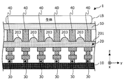
- FIG. 1A is a cross-sectional view schematically showing an example of the cross-sectional structure of the biological information acquiring apparatus according to this embodiment capable of acquiring biological information as described above
- FIG. 1B is a living body according to this embodiment. It is a sectional view showing typically another example of the section structure of an information acquisition device.
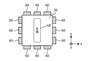
- FIG. 2 is an explanatory diagram for describing the biological information acquisition apparatus according to the present embodiment.
- the biological information acquisition apparatus 1 includes an image sensor 10 on which biological information as image information obtained from a living body LB is formed, an image sensor 10 and a living body LB.
- a lens array 20 positioned between the part and a light shield 30 located between the image sensor 10 and the lens array 20 and forming a light guide path for imaging biological information on the image sensor 10; Prepare.
- the lens array 20 is obtained by arranging a plurality of single lenses 203 in an array on a predetermined base material 201, and the biological information transmitted through each single lens 203 is provided to the image sensor 10 I will image it.
- the space existing between the light shielding members 30 adjacent to each other functions as a light guide.
- the light guide path formed by the light shield 30 has an opening diameter (z-axis direction in FIG. 1A) along the surface normal direction of the image sensor 10. The width of each light guide in FIG. 1A in the y-axis direction is not constant.
- the biological information acquisition apparatus 1 has a lens array 20 between the lens array 20 and a part of the living body LB. And a second light shield 40 forming a second light guide path for guiding biological information to the single lens 203, and a cover glass 50 on the surface of which a part of the living body LB is disposed. Is preferred.
- the biological information acquiring apparatus 1 irradiates light of a predetermined wavelength used for acquiring biological information to a part of the living body LB around the cover glass 50.
- the light source unit 60 is provided.
- a plurality of pixels included in the image sensor 10 are disposed on the surface of the image sensor 10 facing the lens array 20, and the surface functions as a sensor surface of the image sensor 10.
- the biological information obtained from the living body LB is imaged by forming an image on the sensor surface of the image sensor 10, and entity image data regarding the biological information is generated.
- any known image sensor can be used as long as it is an image sensor composed of pixels having sensitivity to the wavelength of light constituting biological information.
- an imaging element a CCD (Charge Coupled Devices) sensor, a CMOS (Complementary Metal Oxide Semiconductor) sensor, etc. can be mentioned, for example.
- the image sensor 10 according to this embodiment may be a color sensor or a monochrome sensor.
- each pixel constituting the image sensor 10 preferably has a pixel size capable of capturing an object having a line width of several ⁇ m to several hundreds of ⁇ m.
- the size of a subject for example, a part of a living body such as a fingerprint or a vein
- M magnification of the single lens 203 provided in the lens array 20
- the subject on the sensor surface The size is p ⁇ M [ ⁇ m].
- Each pixel constituting the image sensor 10 preferably has a pixel size that can express the size of the subject on such a sensor surface with two or more pixels.
- a pixel size for example, a pixel size of about 1 ⁇ m to 4 ⁇ m can be mentioned, but the pixel size of the image sensor 10 according to the present embodiment is not limited to the above.
- Each of the pixels constituting the image sensor 10 has a pixel size capable of imaging an object having a line width of several ⁇ m to several hundreds of ⁇ m, for example, a living body having a resolution of 1000 PPI (Pixel Per Inch) or more It is possible to generate information.
- PPI Pixel Per Inch
- the upper limit value of the resolution is not particularly limited, as it is preferable.
- the lens array 20 is, as mentioned earlier, a plurality of single lenses 203 arranged in an array on a predetermined base material 201, and also referred to as a microlens array.
- the material of the substrate 201 and the single lens 203 is not particularly limited as long as it can transmit light constituting biological information, and any material usable as a material of an optical element can be used.
- the material of can be used. Examples of such materials include various resins represented by thermoplastic resins such as acrylic resins, polycarbonate resins and polyolefin resins, thermosetting resins and the like, and various optical glasses and the like. .
- a desired lens array shape can be realized by molding these materials by a known method, embossing them, processing them by lithography or the like.
- the lens shape of the single lens 203 is not particularly limited, and may be a spherical surface or an aspheric surface.
- FIG. 3 is an enlarged cross-sectional view schematically showing a part of the cross-section of the biological information acquisition apparatus 1 according to the present embodiment
- FIG. 4 is an explanatory view for explaining image overlap by a lens array. is there.
- the lens diameter LS of the lens 203 it is important to reduce the lens diameter LS of the lens 203. Even in such a situation, it is preferable that the lens diameter LS of the single lens 203 be 20 times or more of the pixel size of the image sensor 10.
- an image is guided to the sensor surface of the image sensor so as to include not only an object positioned immediately above each single lens but also a part of an adjacent object. Ru.
- a part of the right end of the triangular object located immediately above the single lens adjacent to the left and the single lens adjacent to the right A portion of the left end portion of the triangular object located immediately above is imaged on the image sensor.
- the lens diameter LS of the single lens 203 shown in FIG. 3 is less than 20 times the pixel size of the image sensor 10, the amount of overlap as described in FIG. 4 (pixels contributing to overlap Number may be insufficient, and it may not be possible to obtain high definition images (ie, more accurate biometric information).
- the lens diameter LS of the single lens 203 By setting the lens diameter LS of the single lens 203 to be at least 20 times the pixel size of the image sensor 10, it is possible to obtain more accurate biological information.
- the upper limit of the size of the lens diameter LS with respect to the pixel size of the image sensor 10 is not particularly limited, and may be appropriately determined in consideration of the amount of overlap as described above.
- the lens magnification of the single lens 203 it is important to set the lens magnification of the single lens 203 to less than 1 in order to cause the overlap as described in FIG. 4.
- the lens magnification of the single lens 203 is 1 or more, the above overlap can not be generated, and the possibility that a high definition image can not be obtained is increased.
- the lens magnification M is set so that the relationship of s ⁇ M> 2 ⁇ N is satisfied. It is important to decide.
- s is the minimum value of the subject size to be resolved
- M is the lens magnification
- N the pixel size of the image sensor.
- the distance (distance A in FIG. 3) from the sensor surface of the image sensor 10 to a part of the living body LB set by the lens array 20 having the single lens 203 as described above is 0.5 mm or more and less than 30 mm. Is preferred. If the distance A is less than 0.5 mm, the manufacturing difficulty is likely to increase. On the other hand, when the distance A is 30 mm or more, the miniaturization of the biological information acquisition apparatus 1 may be insufficient. By setting the distance A to 0.5 mm or more and less than 30 mm, it is possible to further miniaturize the device while suppressing an increase in manufacturing difficulty.
- Each single lens 203 constituting the lens array 20 as described above may be a lens group constituted by a combination of a plurality of lenses.
- an objective lens may be provided between the lens array 20 and the living body LB as a subject.
- the light shield 30 is located between the image sensor 10 and the lens array 20 and forms a light guide path for focusing the biological information on the image sensor 10 as mentioned above.
- the material of the light shielding body 30 is not particularly limited, and various metals such as stainless steel, various resin compositions, and various dielectrics including silicon can be used.
- the entire light guide which is a space formed by the adjacent light shields 30 is the image sensor 10.
- the aperture diameter D is formed so as not to be constant along the surface normal direction (i.e., the z-axis direction).
- the aperture diameter of the light guide does not have a constant value that is the entire light guide, but there is a portion where the aperture diameter is D1 or the aperture diameter is There may be a portion D2, a portion having an opening diameter D3, or a portion having an opening diameter D4.
- the aperture diameter of the light guide is a constant value that is the entire light guide, light (that is, stray light) incident from a portion other than the single lens 203 located immediately above the light guide is the light guide
- the possibility of regular reflection on the wall surface to reach the image sensor 10 is high.
- FIG. 1 the aperture diameter of the light guide
- the aperture diameter of the light guide does not have a certain value, and as a result, the wall surface of the light guide has an uneven shape, whereby the incident stray light is guided. Even if reflection is performed by the wall surface of the optical path, the stray light intensity is attenuated while the reflection is repeated by the wall surface of the light guide, and the possibility that the reflected stray light reaches the image sensor 10 can be reduced. Thus, in the biological information acquiring apparatus 1 according to the present embodiment, the generation of stray light can be further suppressed even in the case of further downsizing and thinning of the apparatus.
- the aperture diameter D of the light guiding path is preferably twice or more the wavelength of the light forming the biological information, and preferably 4.0 times or less the lens diameter LS of the single lens 203.
- the aperture diameter D is less than twice the wavelength of light, there is a high possibility that the light diffraction phenomenon occurs in the light guide, and noise is superimposed on the biological information formed on the image sensor 10 there is a possibility.
- the aperture diameter D exceeds 4.0 times the lens diameter LS of the single lens 203, stray light entering the light guide may increase.
- the size of the aperture diameter D of the light guide can be variously changed along the surface normal direction (z-axis direction) of the image sensor 10 within the range satisfying the above conditions.
- the aperture diameter D of the light guide is reduced and becomes smaller than the lens diameter LS of the single lens 203, the influence of the end portion of the single lens 203 which may have degraded lens characteristics can be excluded. Since it becomes easy to suppress the stray light from the adjacent light guide path, the obtained image quality becomes high.
- the aperture diameter D of the light guide decreases, the angle of view narrows.
- the center distance (so-called lens pitch) between adjacent single lenses 203 is set. Narrowing is important. Therefore, higher accuracy may be required to manufacture the lens array 20 having a narrow lens pitch.
- the aperture diameter D of the light guide is more preferably 0.5 times or more and 4.0 times or less the lens diameter LS of the single lens 203.
- the optical path length (the length L1 in FIG. 3) of the light guide path formed by the adjacent light shields 30 be less than the back focus length of the lens array 20 .
- the distance from the sensor surface of the image sensor 10 to a part of the living body LB is A [mm] and the lens magnification of the single lens 203 is M
- the back focus length of the lens array 20 is (A ⁇ M ) / (1 + M) [mm]. Therefore, the light path length L1 of the light guide is preferably less than (A ⁇ M) / (1 + M) [mm].
- each light blocking member 30 has two or more light blocking members having a predetermined shape in the surface normal direction (z-axis direction) of the image sensor 10. It may be a laminated body laminated along, or may be formed of one light shielding member.
- the outer shape of the light shield 30 facing the light guide is shown in FIG. 1A, FIG. 1B and FIG. As shown, it may be comprised by a straight line, and may be comprised by the curve.
- the outer shape of the light shielding body 30 facing the light guide path may be a straight line and a curved line. Good.
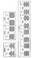
- FIGS. FIG. 5 to FIG. 8 are explanatory diagrams for describing a light shielding body included in the biological information acquiring apparatus according to the present embodiment.
- the outer shape of the light shielding body 30 facing the light guide is a linear shape configured by a straight line substantially parallel to the surface normal direction (z-axis direction) of the image sensor 10 as illustrated in the upper left of FIG. And as illustrated in the lower part of FIG. 5, it may have a tapered shape constituted by a straight line not parallel to the surface normal direction (z-axis direction) of the image sensor 10.
- the aperture diameter is in the surface normal direction of the image sensor 10 (z axis Will change discontinuously).
- the aperture diameter is in the surface normal direction of the image sensor 10 ( It changes continuously along the z-axis direction).
- the outer shape of the light shielding body 30 facing the light guide path may be a concave shape as exemplified in the upper right of FIG. 5 or may be a convex shape.
- the outer shape of the light shielding body 30 having the concave shape and the convex shape facing the light guide path is formed by a curve as shown in the upper right of FIG.
- the aperture diameter is continuous along the surface normal direction (z-axis direction) of the image sensor 10.
- the external shape of the light shielding body 30 is not limited to what was illustrated in FIG. 5,
- the light shielding member which has a rectangular shape, the light shielding member which has a taper shape, and the light shielding member which has convex shape or concave shape And can be combined arbitrarily.
- FIG. 5 illustrates the case where four light shielding members having a predetermined shape are stacked
- the number of stacked layers may be two or three, or five or more. .
- each light shielding member may be the same for each light shielding member as illustrated in FIG. 5, or different for each light shielding member as illustrated in FIG. 6. May be Although FIG. 6 shows the case where the heights h1 to h4 of the respective light shielding members are different in the light shielding body 30 in which the number of laminated layers is four, the opening diameter of the light guide is not constant along the z axis direction.
- the combination of the heights h of the respective light shielding members is not particularly limited as long as
- the absorptivity of light at a predetermined wavelength (for example, the wavelength of light constituting biological information, or biological information is acquired on the surface of the light shield 30 facing the light guide. Therefore, it is preferable to provide the absorber 301 whose absorption factor at the wavelength of the light to be irradiated is 90% or more.
- stray light is absorbed by the absorber 301 each time light incident on the light guide as stray light reaches the wall surface of the light shield 30. As a result, it is possible to more reliably reduce stray light reaching the image sensor 10, and it is possible to acquire higher definition biological information.
- the material of the absorber 301 is not particularly limited, and any known material may be used in consideration of the wavelength of light to be absorbed.
- various types of specular reflection preventing processes such as forming fine asperities and plating a metal having a predetermined surface roughness, on the surface of the light shielding body 30 facing the light guide, etc. You may By performing such regular reflection preventing processing, it is possible to more reliably reduce stray light reaching the image sensor 10, and it is possible to acquire higher definition biological information. In addition, by providing the above-mentioned absorber 301 and further performing regular reflection prevention processing, it becomes possible to more reliably reduce stray light reaching the image sensor 10, and biological information with even higher definition is obtained. It is possible to
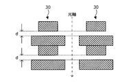
- the light shielding members having a predetermined shape are stacked so that there is no gap between the light shielding members.
- a gap d of a predetermined thickness may be present between adjacent light shielding members.
- FIG. 9 is an enlarged sectional view schematically showing a part of the cross section of the biological information acquiring apparatus according to the present embodiment.
- the biological information acquiring apparatus 1 preferably further includes a second light shield 40 above the lens array 20 on the side where the single lens 203 is present.
- the adjacent second light shields 40 form a second light guide path for guiding biological information from a part of the living body LB to the single lens 203.
- the second light shield 40 may be formed using at least one of various metals such as stainless steel, various resin compositions, and various dielectrics including silicon. Is possible.
- the height (the length L2 in the z-axis direction in FIG. 9) of the second light shield 40 is not particularly limited, the second light shield 40 functions as a stop, The height is preferably as small as possible, and may be appropriately determined in consideration of the easiness of manufacturing the second light shield 40 and the quality of the obtained biological information.
- the aperture diameter D ′ of the second light guide formed by the adjacent second light shields 40 is larger than the lens diameter LS of the single lens 203 (D ′> LS), and the lens of the single lens 203 The closer to the diameter LS the better.
- the aperture diameter D 'of the second light guide path is equal to the lens diameter LS of the single lens 203, it may be difficult to realize the overlap described above.
- the aperture diameter D 'of the second light guide path has a value closer to the lens diameter LS of the single lens 203, it becomes possible to more reliably prevent the stray light from entering the single lens 203.
- each component of the biological information acquiring apparatus 1 is protected between the second light shield 40 and a part of the living body LB, and a part of the living body LB is disposed.
- a cover glass 50 is provided.
- the material of the cover glass 50 is not particularly limited as long as it can transmit light forming biological information, and any material that can be used as a material of an optical element can be used.
- examples of such materials include various resins represented by thermoplastic resins such as acrylic resins, polycarbonate resins and polyolefin resins, thermosetting resins and the like, and various optical glasses and the like.
- the cover glass 50 is preferably formed using various resins from the viewpoint of strength, impact resistance, and the like.
- the thickness of the cover glass 50 is not particularly limited, and may be set as appropriate.
- FIG. 1B and FIG. 9 illustrate the case where the cover glass 50 is provided to be in contact with the second light shield 40, an air layer may be formed between the second light shield 40 and the cover glass 50. (Ie, an air gap) may be present.
- FIG. 1B and FIG. 9 although illustrated about the case where the biometric information acquisition apparatus 1 which concerns on this embodiment further equips both the 2nd light-shielding body 40 and the cover glass 50, the biological body which concerns on this embodiment is shown.
- the information acquisition device 1 may include the cover glass 50 without providing the second light shield 40.
- a light source unit 60 is provided around the cover glass 50 to irradiate light of a predetermined wavelength used for acquiring biological information to a part of the living body LB.
- the light source unit 60 is not particularly limited, and various known light sources such as various diodes and semiconductor lasers may be used as long as they can emit light of a wavelength necessary to acquire biological information. It is possible.
- the number and arrangement of the light source units 60 are not limited to the example shown in FIG. 2 and may be determined according to the size of the region of the living body LB to be measured, the size of the biological information acquisition apparatus 1, etc. And may be set as appropriate. Further, the arrangement position of the light source unit 60 is not limited to the position shown in FIG. 2 and can be arranged at an arbitrary position.
- the structure of the biological information acquiring apparatus 1 according to the present embodiment has been described in detail with reference to FIGS. 1A to 9.
- the method of manufacturing the biological information acquisition apparatus 1 according to the present embodiment is not particularly limited, and any method including a known method used in a semiconductor manufacturing process or the like may be appropriately used in the present embodiment. It is possible to manufacture the living body information acquisition device 1 concerned.
- an image sensor satisfying the conditions as described above is prepared, and the light shield 30 according to the present embodiment is formed on the image sensor 10 using a known method used in a semiconductor manufacturing process or the like.
- the lens array 20 satisfying the conditions as described above may be separately manufactured by a known method, and the lens array 20 may be disposed on the upper side of the light shielding body 30 formed.
- ⁇ About the biological information acquisition method> using the biological information acquisition apparatus 1 in which the light guide is formed so that the aperture diameter is not constant along the surface normal direction of the image sensor, a predetermined wavelength for a part of the living body LB Image information obtained by irradiating the image light through the light guide path formed of the light shielding body 30 using the lens array 20 in which the plurality of single lenses 203 are arranged in an array, and the image sensor Focus on 10
- image information related to fingerprints for example, a fingerprint pattern image showing a distribution of fingerprints etc.
- image information related to sweating eg an image showing presence or absence of perspiration
- image information related to blood flow It is possible to accurately acquire various types of biological information such as image information on waves or pulse, or image information on blood vessels (for example, vein pattern images indicating the distribution of veins).
- the biometric information acquisition device 1 implements biometric authentication processing using biometric information, and provides any known device that provides various services according to the authentication result. In contrast, it is possible to implement.
- the biological information acquisition apparatus 1 according to the present embodiment can further suppress the generation of stray light, so that biological information can be acquired more accurately. Therefore, by using the acquired biometric information, the authentication of the user can be performed more accurately.
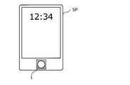
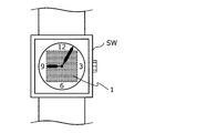
- the biometric information acquisition apparatus 1 may be a smart phone SP or a tablet terminal as shown in FIG. 10A, a mobile device such as a portable music player, a portable game machine, a smart watch SW as shown in FIG. Etc., or various stationary devices.
- the biological information acquisition apparatus 1 according to the present embodiment can also be mounted on an external device that is mounted on various types of stationary devices.
- the biological information acquisition apparatus 1 according to the present embodiment is mounted on various wearable devices, a device main body provided so that the user can wear (for example, the main body of the smart watch SW as shown in FIG. 10B)
- the biometric information acquisition apparatus 1 according to the present embodiment is to be implemented in the inside.
- the mounting position of the biological information acquisition apparatus 1 is not particularly limited, and it can be mounted at any position.
- the biological information acquiring apparatus is continuously changed along the surface normal direction.
- the outer shape of the light shield facing the light guide path is configured by at least one of a straight line and a curved line.
- the biometric information acquisition device according to any one of 3).
- (5) The biological information acquiring apparatus according to any one of (1) to (4), wherein the light shielding body is a laminated body in which two or more light shielding members having a predetermined shape are laminated along the surface normal direction. .
- the biological information acquiring apparatus according to any one of (1) to (8), wherein a distance from a sensor surface of the image sensor to a part of the living body is 0.5 mm or more and less than 30 mm.
- the lens diameter of the single lens is at least 20 times the pixel size of the image sensor, When the lens magnification of the single lens is less than 1 and the minimum value of the subject size to be resolved is s, the lens magnification is M, and the pixel size of the image sensor is N, s ⁇ M
- the biological information acquiring apparatus according to any one of (1) to (9), which satisfies the relationship of> 2 ⁇ N.
- a second light shield that forms a second light guide path for guiding the biological information to the single lens; And a cover glass on which a part of the living body is placed.
- the biological information acquiring apparatus according to any one of (1) to (10), wherein a light source unit configured to irradiate light of the predetermined wavelength to a part of the living body is provided around the cover glass.
- a light source unit configured to irradiate light of the predetermined wavelength to a part of the living body is provided around the cover glass.
- an absorber having an absorptivity of light at a predetermined wavelength of 90% or more is provided on the surface of the light shield facing the light guide.
- the biological information acquiring apparatus according to any one of (1) to (12), wherein the surface of the light shielding member facing the light guide path is subjected to a regular reflection preventing process.
- the biological information acquiring apparatus according to any one of (1) to (13), wherein the light shielding body is made of at least one of a metal, a resin composition, and a dielectric.
- the biological information is at least one of image information on fingerprints, image information on sweating, image information on blood flow, image information on pulse waves or pulses, or image information on blood vessels, The biometric information acquisition device according to any one.
- the biological information at least two types of image information selected from image information on fingerprints, image information on sweating, image information on blood flow, image information on pulse waves or pulse, and image information on blood vessels (1
- the biological information acquiring apparatus according to any one of the above items (15) to (15).
- the mobile device according to any one of (1) to (16), mounted on a mobile device, wearable device, or stationary device, or mounted on an external device attached to the stationary device Biological information acquisition device.
- a living body information which is image information obtained by irradiating a part of a living body with light of a predetermined wavelength, is formed of a light shielding body using a lens array in which a plurality of single lenses are arranged in an array.
- the biological information acquisition method wherein the light guide path is formed such that the aperture diameter is not constant along the surface normal direction of the image sensor.
Landscapes
- Health & Medical Sciences (AREA)
- Life Sciences & Earth Sciences (AREA)
- Engineering & Computer Science (AREA)
- Physics & Mathematics (AREA)
- Animal Behavior & Ethology (AREA)
- General Health & Medical Sciences (AREA)
- Biophysics (AREA)
- Pathology (AREA)
- Veterinary Medicine (AREA)
- Biomedical Technology (AREA)
- Heart & Thoracic Surgery (AREA)
- Medical Informatics (AREA)
- Molecular Biology (AREA)
- Surgery (AREA)
- Public Health (AREA)
- Cardiology (AREA)
- Physiology (AREA)
- Hematology (AREA)
- Vascular Medicine (AREA)
- Theoretical Computer Science (AREA)
- Multimedia (AREA)
- General Physics & Mathematics (AREA)
- Human Computer Interaction (AREA)
- Image Input (AREA)
- Measurement Of The Respiration, Hearing Ability, Form, And Blood Characteristics Of Living Organisms (AREA)
- Measuring Pulse, Heart Rate, Blood Pressure Or Blood Flow (AREA)
- Solid State Image Pick-Up Elements (AREA)
- Transforming Light Signals Into Electric Signals (AREA)
Abstract
Description
1.実施形態
1.1.生体情報取得装置の構造について
1.2.生体情報取得装置の製造方法について
1.3.生体情報取得方法について
1.4.生体情報取得装置の実装例について
<生体情報取得装置の構造について>
まず、図1A~図9を参照しながら、本開示の実施形態に係る生体情報取得装置の構造について、詳細に説明する。
イメージセンサ10のレンズアレイ20に対向する面には、イメージセンサ10が備える複数の画素が配設されており、かかる面は、イメージセンサ10のセンサ面として機能する。生体LBから得られる生体情報は、イメージセンサ10のセンサ面に結像することで画像化され、生体情報に関する実体画像データが生成される。
レンズアレイ20は、先だって言及したように、所定の基材201上に複数の単レンズ203がアレイ状に配列されたものであり、マイクロレンズアレイとも呼ばれる。
遮光体30は、先だって言及したように、イメージセンサ10とレンズアレイ20との間に位置し、生体情報をイメージセンサ10に結像させるための導光路を形成する。遮光体30の素材については、特に限定するものではなく、ステンレス等の各種の金属や、各種の樹脂組成物や、シリコンをはじめとする各種の誘電体の少なくとも何れかを用いることができる。
続いて、図1B及び図9を参照しながら、第2の遮光体40について、詳細に説明する。図9は、本実施形態に係る生体情報取得装置の断面の一部を模式的に示した拡大断面図である。
図1B及び図9に示したように、第2の遮光体40と生体LBの一部との間に、生体情報取得装置1の各構成を保護するとともに、生体LBの一部が配設されるカバーガラス50が設けられることが好ましい。
図2に模式的に示したように、カバーガラス50の周囲には、生体情報の取得に用いられる所定波長の光を生体LBの一部へと照射する光源ユニット60が設けられることが好ましい。かかる光源ユニット60は、特に限定されるものではなく、生体情報を取得するために必要な波長の光を出射可能なものであれば、各種のダイオードや半導体レーザなど、公知の様々な光源を用いることが可能である。
本実施形態に係る生体情報取得装置1の製造方法については、特に限定されるものではなく、半導体製造プロセス等で用いられる公知の方法を含む、任意の方法を適宜利用して、本実施形態に係る生体情報取得装置1を製造することが可能である。
以上説明したような、イメージセンサの表面法線方向に沿って、開口径が一定ではないように導光路が形成されている生体情報取得装置1を用い、生体LBの一部に対して所定波長の光を照射することで得られる画像情報である生体情報を、複数の単レンズ203がアレイ状に配列されたレンズアレイ20を用い、遮光体30により形成されている導光路を経て、イメージセンサ10に結像させる。これにより、例えば、指紋に関する画像情報(例えば、指紋の分布の様子を示した指紋パターン画像等)、発汗に関する画像情報(例えば、発汗の有無を示した画像等)、血流に関する画像情報、脈波もしくは脈拍に関する画像情報、又は、血管に関する画像情報(例えば、静脈の分布の様子を示した静脈パターン画像等)等の各種の生体情報を、精度良く取得することが可能となる。
以上説明したような本実施形態に係る生体情報取得装置1は、生体情報を利用して生体認証処理を実施し、その認証結果に応じて各種のサービスを提供するような公知の任意の装置に対して、実装することが可能である。本実施形態に係る生体情報取得装置1は、迷光の発生がより一層抑制されたものであるため、生体情報をより精度良く取得することができる。従って、取得された生体情報を用いることで、ユーザ個人の認証をより精度良く実施することができる。
(1)
生体の一部に対して所定波長の光を照射することで得られる画像情報である生体情報が結像するイメージセンサと、
前記イメージセンサと前記生体の一部との間に位置しており、複数の単レンズがアレイ状に配列されており、前記生体情報を前記イメージセンサに結像させるレンズアレイと、
前記イメージセンサと前記レンズアレイとの間に位置し、それぞれの前記単レンズを透過する前記生体情報を前記イメージセンサに結像させるための導光路を形成する遮光体と、
を備え、
前記導光路は、前記イメージセンサの表面法線方向に沿って、開口径が一定ではないように形成されている、生体情報取得装置。
(2)
前記導光路の開口径は、前記表面法線方向に沿って連続的に変化している、(1)に記載の生体情報取得装置。
(3)
前記導光路の開口径は、前記表面法線方向に沿って不連続に変化している、(1)に記載の生体情報取得装置。
(4)
前記遮光体を前記表面法線方向に対して平行に切断したときに、前記導光路に面する前記遮光体の外形は、直線又は曲線の少なくとも何れか一方で構成される、(1)~(3)の何れか1つに記載の生体情報取得装置。
(5)
前記遮光体は、所定の形状を有する遮光部材が2つ以上前記表面法線方向に沿って積層した積層体である、(1)~(4)の何れか1つに記載の生体情報取得装置。
(6)
前記導光路の開口径は、前記生体情報を構成する光の波長の2倍以上である、(1)~(5)の何れか1つに記載の生体情報取得装置。
(7)
前記導光路の開口径は、前記単レンズのレンズ径の0.5倍以上4.0倍以下である、(1)~(6)の何れか1つに記載の生体情報取得装置。
(8)
前記導光路の長さは、前記イメージセンサのセンサ面から前記生体の一部までの距離をA[mm]とし、前記単レンズのレンズ倍率をMとしたときに、(A×M)/(1+M)[mm]未満である、(1)~(7)の何れか1つに記載の生体情報取得装置。
(9)
前記イメージセンサのセンサ面から前記生体の一部までの距離は、0.5mm以上30mm未満である、(1)~(8)の何れか1つに記載の生体情報取得装置。
(10)
前記単レンズのレンズ径は、前記イメージセンサの画素サイズの20倍以上であり、
前記単レンズのレンズ倍率は、1倍未満であり、かつ、解像したい被写体サイズの最小値をsとし、レンズ倍率をMとし、前記イメージセンサの画素サイズをNとしたときに、s×M>2×Nの関係を満足する、(1)~(9)の何れか1つに記載の生体情報取得装置。
(11)
前記レンズアレイと前記生体の一部との間には、前記レンズアレイの側から順に、前記生体情報を前記単レンズへと導光する第2の導光路を形成する第2の遮光体と、表面に前記生体の一部が配置されるカバーガラスと、が設けられており、
前記カバーガラスの周囲に、前記所定波長の光を前記生体の一部へと照射する光源ユニットが設けられる、(1)~(10)の何れか1つに記載の生体情報取得装置。
(12)
前記導光路に面する前記遮光体の表面に、所定波長における光の吸収率が90%以上である吸収体が設けられている、(1)~(11)の何れか1つに記載の生体情報取得装置。
(13)
前記導光路に面する前記遮光体の表面に、正反射防止加工が施されている、(1)~(12)の何れか1つに記載の生体情報取得装置。
(14)
前記遮光体は、金属、樹脂組成物、又は、誘電体の少なくとも何れかを素材とする、(1)~(13)の何れか1つに記載の生体情報取得装置。
(15)
前記生体情報は、指紋に関する画像情報、発汗に関する画像情報、血流に関する画像情報、脈波もしくは脈拍に関する画像情報、又は、血管に関する画像情報の少なくとも何れかである、(1)~(14)の何れか1つに記載の生体情報取得装置。
(16)
前記生体情報として、指紋に関する画像情報、発汗に関する画像情報、血流に関する画像情報、脈波もしくは脈拍に関する画像情報、及び、血管に関する画像情報から選択される、少なくとも2つの画像情報である、(1)~(15)の何れか1つに記載の生体情報取得装置。
(17)
モバイルデバイス、ウェアラブルデバイス、もしくは、据え置き型デバイスに実装されるか、又は、前記据え置き型デバイスに装着される外付けデバイスに実装される、(1)~(16)の何れか1つに記載の生体情報取得装置。
(18)
生体の一部に対して所定波長の光を照射することで得られる画像情報である生体情報を、複数の単レンズがアレイ状に配列されたレンズアレイを用い、遮光体により形成されている導光路を経てイメージセンサに結像させることを含み、
前記導光路は、前記イメージセンサの表面法線方向に沿って、開口径が一定ではないように形成されている、生体情報取得方法。
(19)
ユーザが装着可能なように設けられたデバイス本体と、
前記デバイス本体に実装された生体情報取得装置と、
を備え、
前記生体情報取得装置は、
生体の一部に対して所定波長の光を照射することで得られる画像情報である生体情報が結像するイメージセンサと、
前記イメージセンサと前記生体の一部との間に位置しており、複数の単レンズがアレイ状に配列されたものであり、前記生体情報を前記イメージセンサに結像させるレンズアレイと、
前記イメージセンサと前記レンズアレイとの間に位置し、それぞれの前記単レンズを透過する前記生体情報を前記イメージセンサに結像させるための導光路を形成する遮光体と、
を有しており、
前記導光路は、前記イメージセンサの表面法線方向に沿って、開口径が一定ではないように形成されている、ウェアラブルデバイス。
10 イメージセンサ
20 レンズアレイ
30 遮光体
40 第2の遮光体
50 カバーガラス
60 光源ユニット
201 基材
203 単レンズ
301 吸収体
Claims (19)
- 生体の一部に対して所定波長の光を照射することで得られる画像情報である生体情報が結像するイメージセンサと、
前記イメージセンサと前記生体の一部との間に位置しており、複数の単レンズがアレイ状に配列されており、前記生体情報を前記イメージセンサに結像させるレンズアレイと、
前記イメージセンサと前記レンズアレイとの間に位置し、それぞれの前記単レンズを透過する前記生体情報を前記イメージセンサに結像させるための導光路を形成する遮光体と、
を備え、
前記導光路は、前記イメージセンサの表面法線方向に沿って、開口径が一定ではないように形成されている、生体情報取得装置。 - 前記導光路の開口径は、前記表面法線方向に沿って連続的に変化している、請求項1に記載の生体情報取得装置。
- 前記導光路の開口径は、前記表面法線方向に沿って不連続に変化している、請求項1に記載の生体情報取得装置。
- 前記遮光体を前記表面法線方向に対して平行に切断したときに、前記導光路に面する前記遮光体の外形は、直線又は曲線の少なくとも何れか一方で構成される、請求項1に記載の生体情報取得装置。
- 前記遮光体は、所定の形状を有する遮光部材が2つ以上前記表面法線方向に沿って積層した積層体である、請求項1に記載の生体情報取得装置。
- 前記導光路の開口径は、前記生体情報を構成する光の波長の2倍以上である、請求項1に記載の生体情報取得装置。
- 前記導光路の開口径は、前記単レンズのレンズ径の0.5倍以上4.0倍以下である、請求項1に記載の生体情報取得装置。
- 前記導光路の長さは、前記イメージセンサのセンサ面から前記生体の一部までの距離をA[mm]とし、前記単レンズのレンズ倍率をMとしたときに、(A×M)/(1+M)[mm]未満である、請求項1に記載の生体情報取得装置。
- 前記イメージセンサのセンサ面から前記生体の一部までの距離は、0.5mm以上30mm未満である、請求項1に記載の生体情報取得装置。
- 前記単レンズのレンズ径は、前記イメージセンサの画素サイズの20倍以上であり、
前記単レンズのレンズ倍率は、1倍未満であり、かつ、解像したい被写体サイズの最小値をsとし、レンズ倍率をMとし、前記イメージセンサの画素サイズをNとしたときに、s×M>2×Nの関係を満足する、請求項1に記載の生体情報取得装置。 - 前記レンズアレイと前記生体の一部との間には、前記レンズアレイの側から順に、前記生体情報を前記単レンズへと導光する第2の導光路を形成する第2の遮光体と、表面に前記生体の一部が配置されるカバーガラスと、が設けられており、
前記カバーガラスの周囲に、前記所定波長の光を前記生体の一部へと照射する光源ユニットが設けられる、請求項1に記載の生体情報取得装置。 - 前記導光路に面する前記遮光体の表面に、所定波長における光の吸収率が90%以上である吸収体が設けられている、請求項1に記載の生体情報取得装置。
- 前記導光路に面する前記遮光体の表面に、正反射防止加工が施されている、請求項1に記載の生体情報取得装置。
- 前記遮光体は、金属、樹脂組成物、又は、誘電体の少なくとも何れかを素材とする、請求項1に記載の生体情報取得装置。
- 前記生体情報は、指紋に関する画像情報、発汗に関する画像情報、血流に関する画像情報、脈波もしくは脈拍に関する画像情報、又は、血管に関する画像情報の少なくとも何れかである、請求項1に記載の生体情報取得装置。
- 前記生体情報として、指紋に関する画像情報、発汗に関する画像情報、血流に関する画像情報、脈波もしくは脈拍に関する画像情報、及び、血管に関する画像情報から選択される、少なくとも2つの画像情報である、請求項1に記載の生体情報取得装置。
- モバイルデバイス、ウェアラブルデバイス、もしくは、据え置き型デバイスに実装されるか、又は、前記据え置き型デバイスに装着される外付けデバイスに実装される、請求項1に記載の生体情報取得装置。
- 生体の一部に対して所定波長の光を照射することで得られる画像情報である生体情報を、複数の単レンズがアレイ状に配列されたレンズアレイを用い、遮光体により形成されている導光路を経てイメージセンサに結像させることを含み、
前記導光路は、前記イメージセンサの表面法線方向に沿って、開口径が一定ではないように形成されている、生体情報取得方法。 - ユーザが装着可能なように設けられたデバイス本体と、
前記デバイス本体に実装された生体情報取得装置と、
を備え、
前記生体情報取得装置は、
生体の一部に対して所定波長の光を照射することで得られる画像情報である生体情報が結像するイメージセンサと、
前記イメージセンサと前記生体の一部との間に位置しており、複数の単レンズがアレイ状に配列されたものであり、前記生体情報を前記イメージセンサに結像させるレンズアレイと、
前記イメージセンサと前記レンズアレイとの間に位置し、それぞれの前記単レンズを透過する前記生体情報を前記イメージセンサに結像させるための導光路を形成する遮光体と、
を有しており、
前記導光路は、前記イメージセンサの表面法線方向に沿って、開口径が一定ではないように形成されている、ウェアラブルデバイス。
Priority Applications (4)
| Application Number | Priority Date | Filing Date | Title |
|---|---|---|---|
| CN201880085725.1A CN111557050A (zh) | 2018-01-15 | 2018-10-17 | 生物体信息获取装置、生物体信息获取方法和可穿戴装置 |
| EP18899823.1A EP3742489A4 (en) | 2018-01-15 | 2018-10-17 | DEVICE AND METHOD FOR COLLECTING INFORMATION FROM A LIVING BODY AND WEARABLE DEVICE |
| JP2019564293A JPWO2019138633A1 (ja) | 2018-01-15 | 2018-10-17 | 生体情報取得装置、生体情報取得方法及びウェアラブルデバイス |
| US16/960,770 US20200359915A1 (en) | 2018-01-15 | 2018-10-17 | Biological information obtaining device, biological information obtaining method, and wearable device |
Applications Claiming Priority (2)
| Application Number | Priority Date | Filing Date | Title |
|---|---|---|---|
| JP2018004015 | 2018-01-15 | ||
| JP2018-004015 | 2018-01-15 |
Publications (1)
| Publication Number | Publication Date |
|---|---|
| WO2019138633A1 true WO2019138633A1 (ja) | 2019-07-18 |
Family
ID=67218568
Family Applications (1)
| Application Number | Title | Priority Date | Filing Date |
|---|---|---|---|
| PCT/JP2018/038583 Ceased WO2019138633A1 (ja) | 2018-01-15 | 2018-10-17 | 生体情報取得装置、生体情報取得方法及びウェアラブルデバイス |
Country Status (5)
| Country | Link |
|---|---|
| US (1) | US20200359915A1 (ja) |
| EP (1) | EP3742489A4 (ja) |
| JP (1) | JPWO2019138633A1 (ja) |
| CN (1) | CN111557050A (ja) |
| WO (1) | WO2019138633A1 (ja) |
Cited By (1)
| Publication number | Priority date | Publication date | Assignee | Title |
|---|---|---|---|---|
| WO2022058815A1 (en) * | 2020-09-18 | 2022-03-24 | 3M Innovative Properties Company | Optical construction and optical system including light absorbing optical cavity |
Families Citing this family (3)
| Publication number | Priority date | Publication date | Assignee | Title |
|---|---|---|---|---|
| KR20220035438A (ko) * | 2019-07-23 | 2022-03-22 | 쓰리엠 이노베이티브 프로퍼티즈 컴파니 | 마이크로렌즈 및 차광 구조체를 포함하는 광학 시스템 |
| KR102812791B1 (ko) * | 2020-03-02 | 2025-05-23 | 삼성전자주식회사 | 이미지 센서 |
| KR20210138184A (ko) * | 2020-05-11 | 2021-11-19 | 삼성디스플레이 주식회사 | 지문 센서, 및 그를 포함한 표시 장치 |
Citations (7)
| Publication number | Priority date | Publication date | Assignee | Title |
|---|---|---|---|---|
| JP2007329714A (ja) * | 2006-06-08 | 2007-12-20 | Funai Electric Co Ltd | 複眼撮像装置 |
| JP2008036058A (ja) * | 2006-08-04 | 2008-02-21 | Hitachi Maxell Ltd | 撮像装置および生体認証装置 |
| JP2009164654A (ja) * | 2006-04-24 | 2009-07-23 | Panasonic Corp | 複眼方式のカメラモジュール |
| JP2009276976A (ja) * | 2008-05-14 | 2009-11-26 | Hitachi Maxell Ltd | 撮像装置及び生体情報取得装置 |
| JP2010098055A (ja) * | 2008-10-15 | 2010-04-30 | Hitachi Maxell Ltd | 遮光構造、撮像装置及びその製造方法、並びに生体情報取得装置 |
| JP2011203792A (ja) | 2010-03-24 | 2011-10-13 | Hitachi Displays Ltd | 撮像装置 |
| JP2017196319A (ja) * | 2016-04-28 | 2017-11-02 | ソニー株式会社 | 撮像装置、認証処理装置、撮像方法、認証処理方法およびプログラム |
Family Cites Families (11)
| Publication number | Priority date | Publication date | Assignee | Title |
|---|---|---|---|---|
| WO2006077718A1 (ja) * | 2005-01-20 | 2006-07-27 | Matsushita Electric Industrial Co., Ltd. | レンズアレイ及びレンズアレイを備えるイメージセンサ |
| JP4950103B2 (ja) * | 2007-08-20 | 2012-06-13 | 日本板硝子株式会社 | 正立等倍レンズアレイプレート、イメージセンサユニットおよび画像読取装置 |
| JP2010094499A (ja) * | 2008-09-16 | 2010-04-30 | Hitachi Maxell Ltd | 画像取得装置及び生体情報取得装置 |
| US9122097B2 (en) * | 2010-04-27 | 2015-09-01 | Sharp Kabushiki Kaisha | Backlight system and LCD device using the same |
| JP5817301B2 (ja) * | 2011-08-02 | 2015-11-18 | ソニー株式会社 | 撮像素子、並びに、撮像装置および方法 |
| JP5536150B2 (ja) * | 2011-08-09 | 2014-07-02 | キヤノン・コンポーネンツ株式会社 | イメージセンサユニット及び画像読取装置 |
| CN102542258B (zh) * | 2011-12-16 | 2013-11-20 | 天津理工大学 | 基于手指生物特征信息的成像设备及多模态身份识别方法 |
| US20130237856A1 (en) * | 2012-03-12 | 2013-09-12 | Ivwatch, Llc | Apparatus and Method for Mitigating Noise Affecting a Transcutaneous Signal |
| US20140073969A1 (en) * | 2012-09-12 | 2014-03-13 | Neurosky, Inc. | Mobile cardiac health monitoring |
| JP5862731B1 (ja) * | 2014-08-27 | 2016-02-16 | セイコーエプソン株式会社 | センサー及び生体情報検出装置 |
| JP2016115862A (ja) * | 2014-12-17 | 2016-06-23 | セイコーエプソン株式会社 | 画像取得装置、生体情報取得装置、電子機器 |
-
2018
- 2018-10-17 WO PCT/JP2018/038583 patent/WO2019138633A1/ja not_active Ceased
- 2018-10-17 US US16/960,770 patent/US20200359915A1/en not_active Abandoned
- 2018-10-17 JP JP2019564293A patent/JPWO2019138633A1/ja active Pending
- 2018-10-17 EP EP18899823.1A patent/EP3742489A4/en not_active Ceased
- 2018-10-17 CN CN201880085725.1A patent/CN111557050A/zh active Pending
Patent Citations (7)
| Publication number | Priority date | Publication date | Assignee | Title |
|---|---|---|---|---|
| JP2009164654A (ja) * | 2006-04-24 | 2009-07-23 | Panasonic Corp | 複眼方式のカメラモジュール |
| JP2007329714A (ja) * | 2006-06-08 | 2007-12-20 | Funai Electric Co Ltd | 複眼撮像装置 |
| JP2008036058A (ja) * | 2006-08-04 | 2008-02-21 | Hitachi Maxell Ltd | 撮像装置および生体認証装置 |
| JP2009276976A (ja) * | 2008-05-14 | 2009-11-26 | Hitachi Maxell Ltd | 撮像装置及び生体情報取得装置 |
| JP2010098055A (ja) * | 2008-10-15 | 2010-04-30 | Hitachi Maxell Ltd | 遮光構造、撮像装置及びその製造方法、並びに生体情報取得装置 |
| JP2011203792A (ja) | 2010-03-24 | 2011-10-13 | Hitachi Displays Ltd | 撮像装置 |
| JP2017196319A (ja) * | 2016-04-28 | 2017-11-02 | ソニー株式会社 | 撮像装置、認証処理装置、撮像方法、認証処理方法およびプログラム |
Non-Patent Citations (1)
| Title |
|---|
| See also references of EP3742489A4 |
Cited By (2)
| Publication number | Priority date | Publication date | Assignee | Title |
|---|---|---|---|---|
| WO2022058815A1 (en) * | 2020-09-18 | 2022-03-24 | 3M Innovative Properties Company | Optical construction and optical system including light absorbing optical cavity |
| JP2023542160A (ja) * | 2020-09-18 | 2023-10-05 | スリーエム イノベイティブ プロパティズ カンパニー | 光吸収光学キャビティを含む、光学構造体及び光学システム |
Also Published As
| Publication number | Publication date |
|---|---|
| EP3742489A4 (en) | 2021-06-23 |
| EP3742489A1 (en) | 2020-11-25 |
| CN111557050A (zh) | 2020-08-18 |
| JPWO2019138633A1 (ja) | 2021-03-04 |
| US20200359915A1 (en) | 2020-11-19 |
Similar Documents
| Publication | Publication Date | Title |
|---|---|---|
| JP7420849B2 (ja) | 複数のf値レンズのための方法およびシステム | |
| JP4545190B2 (ja) | 撮像装置 | |
| WO2019138633A1 (ja) | 生体情報取得装置、生体情報取得方法及びウェアラブルデバイス | |
| CN105122092B (zh) | 相位滤波器、光学成像系统以及成像系统 | |
| WO2022174120A1 (en) | Metasurface, metalens, and metalens array with controllable angular field-of-view | |
| US20170168200A1 (en) | Image acquisition system | |
| US20130063399A1 (en) | Optical Pointing Device, And Electronic Apparatus Provided With Same | |
| JP2011203792A (ja) | 撮像装置 | |
| US20250377490A1 (en) | Imaging lens, light blocking sheet and electronic device | |
| US10606050B2 (en) | Portrait lens system suitable for use in a mobile camera | |
| JP2009225064A (ja) | 画像入力装置、認証装置、およびそれらを搭載した電子機器 | |
| JPWO2005107243A1 (ja) | 撮像装置及び微小レンズアレイの製造方法 | |
| KR101580463B1 (ko) | 홍채인식용 렌즈 | |
| JP2016080865A (ja) | カメラモジュール及び電子機器 | |
| JP4767915B2 (ja) | 撮像装置及び生体認証装置 | |
| CN112335049A (zh) | 成像组件、触摸屏、摄像模组、智能终端、相机和距离测量方法 | |
| US9274323B1 (en) | Hypercentric lens assembly with high numeric aperture aspheric element | |
| US20120287500A1 (en) | Optical lens and optical microscope system using the same | |
| JP7246948B2 (ja) | 固体撮像装置及び電子機器 | |
| US20240272426A1 (en) | Metalens and metalens array with extended depth-of-view and bounded angular field-of-view | |
| WO2015182488A1 (ja) | 複眼撮像光学系及び複眼撮像装置 | |
| TW201122599A (en) | Camera module | |
| JP2017207720A (ja) | 撮像光学系及び撮像装置 | |
| EP3129819B1 (en) | Image acquisition system | |
| JP5889684B2 (ja) | 正立等倍レンズアレイユニットおよび画像読取装置 |
Legal Events
| Date | Code | Title | Description |
|---|---|---|---|
| 121 | Ep: the epo has been informed by wipo that ep was designated in this application |
Ref document number: 18899823 Country of ref document: EP Kind code of ref document: A1 |
|
| ENP | Entry into the national phase |
Ref document number: 2019564293 Country of ref document: JP Kind code of ref document: A |
|
| NENP | Non-entry into the national phase |
Ref country code: DE |
|
| ENP | Entry into the national phase |
Ref document number: 2018899823 Country of ref document: EP Effective date: 20200817 |
|
| WWW | Wipo information: withdrawn in national office |
Ref document number: 2018899823 Country of ref document: EP |