WO2019138746A1 - 内燃機関の燃料噴射量制御方法 - Google Patents
内燃機関の燃料噴射量制御方法 Download PDFInfo
- Publication number
- WO2019138746A1 WO2019138746A1 PCT/JP2018/045012 JP2018045012W WO2019138746A1 WO 2019138746 A1 WO2019138746 A1 WO 2019138746A1 JP 2018045012 W JP2018045012 W JP 2018045012W WO 2019138746 A1 WO2019138746 A1 WO 2019138746A1
- Authority
- WO
- WIPO (PCT)
- Prior art keywords
- amount
- injector
- component
- fuel
- wear
- Prior art date
- Legal status (The legal status is an assumption and is not a legal conclusion. Google has not performed a legal analysis and makes no representation as to the accuracy of the status listed.)
- Ceased
Links
Images




Classifications
-
- F—MECHANICAL ENGINEERING; LIGHTING; HEATING; WEAPONS; BLASTING
- F02—COMBUSTION ENGINES; HOT-GAS OR COMBUSTION-PRODUCT ENGINE PLANTS
- F02D—CONTROLLING COMBUSTION ENGINES
- F02D41/00—Electrical control of supply of combustible mixture or its constituents
- F02D41/30—Controlling fuel injection
- F02D41/32—Controlling fuel injection of the low pressure type
- F02D41/34—Controlling fuel injection of the low pressure type with means for controlling injection timing or duration
- F02D41/345—Controlling injection timing
-
- F—MECHANICAL ENGINEERING; LIGHTING; HEATING; WEAPONS; BLASTING
- F02—COMBUSTION ENGINES; HOT-GAS OR COMBUSTION-PRODUCT ENGINE PLANTS
- F02D—CONTROLLING COMBUSTION ENGINES
- F02D41/00—Electrical control of supply of combustible mixture or its constituents
- F02D41/30—Controlling fuel injection
- F02D41/38—Controlling fuel injection of the high pressure type
- F02D41/40—Controlling fuel injection of the high pressure type with means for controlling injection timing or duration
-
- F—MECHANICAL ENGINEERING; LIGHTING; HEATING; WEAPONS; BLASTING
- F02—COMBUSTION ENGINES; HOT-GAS OR COMBUSTION-PRODUCT ENGINE PLANTS
- F02D—CONTROLLING COMBUSTION ENGINES
- F02D41/00—Electrical control of supply of combustible mixture or its constituents
- F02D41/22—Safety or indicating devices for abnormal conditions
-
- F—MECHANICAL ENGINEERING; LIGHTING; HEATING; WEAPONS; BLASTING
- F02—COMBUSTION ENGINES; HOT-GAS OR COMBUSTION-PRODUCT ENGINE PLANTS
- F02D—CONTROLLING COMBUSTION ENGINES
- F02D41/00—Electrical control of supply of combustible mixture or its constituents
- F02D41/22—Safety or indicating devices for abnormal conditions
- F02D41/221—Safety or indicating devices for abnormal conditions relating to the failure of actuators or electrically driven elements
-
- F—MECHANICAL ENGINEERING; LIGHTING; HEATING; WEAPONS; BLASTING
- F02—COMBUSTION ENGINES; HOT-GAS OR COMBUSTION-PRODUCT ENGINE PLANTS
- F02D—CONTROLLING COMBUSTION ENGINES
- F02D41/00—Electrical control of supply of combustible mixture or its constituents
- F02D41/24—Electrical control of supply of combustible mixture or its constituents characterised by the use of digital means
- F02D41/2406—Electrical control of supply of combustible mixture or its constituents characterised by the use of digital means using essentially read only memories
- F02D41/2425—Particular ways of programming the data
- F02D41/2429—Methods of calibrating or learning
- F02D41/2451—Methods of calibrating or learning characterised by what is learned or calibrated
- F02D41/2464—Characteristics of actuators
- F02D41/2467—Characteristics of actuators for injectors
-
- F—MECHANICAL ENGINEERING; LIGHTING; HEATING; WEAPONS; BLASTING
- F02—COMBUSTION ENGINES; HOT-GAS OR COMBUSTION-PRODUCT ENGINE PLANTS
- F02D—CONTROLLING COMBUSTION ENGINES
- F02D41/00—Electrical control of supply of combustible mixture or its constituents
- F02D41/24—Electrical control of supply of combustible mixture or its constituents characterised by the use of digital means
- F02D41/2406—Electrical control of supply of combustible mixture or its constituents characterised by the use of digital means using essentially read only memories
- F02D41/2425—Particular ways of programming the data
- F02D41/2487—Methods for rewriting
- F02D41/2493—Resetting of data to a predefined set of values
-
- F—MECHANICAL ENGINEERING; LIGHTING; HEATING; WEAPONS; BLASTING
- F02—COMBUSTION ENGINES; HOT-GAS OR COMBUSTION-PRODUCT ENGINE PLANTS
- F02M—SUPPLYING COMBUSTION ENGINES IN GENERAL WITH COMBUSTIBLE MIXTURES OR CONSTITUENTS THEREOF
- F02M47/00—Fuel-injection apparatus operated cyclically with fuel-injection valves actuated by fluid pressure
- F02M47/02—Fuel-injection apparatus operated cyclically with fuel-injection valves actuated by fluid pressure of accumulator-injector type, i.e. having fuel pressure of accumulator tending to open, and fuel pressure in other chamber tending to close, injection valves and having means for periodically releasing that closing pressure
- F02M47/027—Electrically actuated valves draining the chamber to release the closing pressure
-
- F—MECHANICAL ENGINEERING; LIGHTING; HEATING; WEAPONS; BLASTING
- F02—COMBUSTION ENGINES; HOT-GAS OR COMBUSTION-PRODUCT ENGINE PLANTS
- F02M—SUPPLYING COMBUSTION ENGINES IN GENERAL WITH COMBUSTIBLE MIXTURES OR CONSTITUENTS THEREOF
- F02M51/00—Fuel-injection apparatus characterised by being operated electrically
- F02M51/06—Injectors peculiar thereto with means directly operating the valve needle
- F02M51/061—Injectors peculiar thereto with means directly operating the valve needle using electromagnetic operating means
-
- F—MECHANICAL ENGINEERING; LIGHTING; HEATING; WEAPONS; BLASTING
- F02—COMBUSTION ENGINES; HOT-GAS OR COMBUSTION-PRODUCT ENGINE PLANTS
- F02M—SUPPLYING COMBUSTION ENGINES IN GENERAL WITH COMBUSTIBLE MIXTURES OR CONSTITUENTS THEREOF
- F02M61/00—Fuel-injectors not provided for in groups F02M39/00 - F02M57/00 or F02M67/00
- F02M61/04—Fuel-injectors not provided for in groups F02M39/00 - F02M57/00 or F02M67/00 having valves, e.g. having a plurality of valves in series
- F02M61/10—Other injectors with elongated valve bodies, i.e. of needle-valve type
-
- F—MECHANICAL ENGINEERING; LIGHTING; HEATING; WEAPONS; BLASTING
- F02—COMBUSTION ENGINES; HOT-GAS OR COMBUSTION-PRODUCT ENGINE PLANTS
- F02M—SUPPLYING COMBUSTION ENGINES IN GENERAL WITH COMBUSTIBLE MIXTURES OR CONSTITUENTS THEREOF
- F02M61/00—Fuel-injectors not provided for in groups F02M39/00 - F02M57/00 or F02M67/00
- F02M61/16—Details not provided for in, or of interest apart from, the apparatus of groups F02M61/02 - F02M61/14
- F02M61/18—Injection nozzles, e.g. having valve seats; Details of valve member seated ends, not otherwise provided for
-
- F—MECHANICAL ENGINEERING; LIGHTING; HEATING; WEAPONS; BLASTING
- F02—COMBUSTION ENGINES; HOT-GAS OR COMBUSTION-PRODUCT ENGINE PLANTS
- F02M—SUPPLYING COMBUSTION ENGINES IN GENERAL WITH COMBUSTIBLE MIXTURES OR CONSTITUENTS THEREOF
- F02M61/00—Fuel-injectors not provided for in groups F02M39/00 - F02M57/00 or F02M67/00
- F02M61/16—Details not provided for in, or of interest apart from, the apparatus of groups F02M61/02 - F02M61/14
- F02M61/20—Closing valves mechanically, e.g. arrangements of springs or weights or permanent magnets; Damping of valve lift
-
- F—MECHANICAL ENGINEERING; LIGHTING; HEATING; WEAPONS; BLASTING
- F02—COMBUSTION ENGINES; HOT-GAS OR COMBUSTION-PRODUCT ENGINE PLANTS
- F02D—CONTROLLING COMBUSTION ENGINES
- F02D41/00—Electrical control of supply of combustible mixture or its constituents
- F02D41/22—Safety or indicating devices for abnormal conditions
- F02D2041/224—Diagnosis of the fuel system
-
- F—MECHANICAL ENGINEERING; LIGHTING; HEATING; WEAPONS; BLASTING
- F02—COMBUSTION ENGINES; HOT-GAS OR COMBUSTION-PRODUCT ENGINE PLANTS
- F02D—CONTROLLING COMBUSTION ENGINES
- F02D41/00—Electrical control of supply of combustible mixture or its constituents
- F02D41/30—Controlling fuel injection
- F02D41/38—Controlling fuel injection of the high pressure type
- F02D2041/389—Controlling fuel injection of the high pressure type for injecting directly into the cylinder
-
- F—MECHANICAL ENGINEERING; LIGHTING; HEATING; WEAPONS; BLASTING
- F02—COMBUSTION ENGINES; HOT-GAS OR COMBUSTION-PRODUCT ENGINE PLANTS
- F02D—CONTROLLING COMBUSTION ENGINES
- F02D2200/00—Input parameters for engine control
- F02D2200/02—Input parameters for engine control the parameters being related to the engine
- F02D2200/06—Fuel or fuel supply system parameters
- F02D2200/0602—Fuel pressure
-
- F—MECHANICAL ENGINEERING; LIGHTING; HEATING; WEAPONS; BLASTING
- F02—COMBUSTION ENGINES; HOT-GAS OR COMBUSTION-PRODUCT ENGINE PLANTS
- F02D—CONTROLLING COMBUSTION ENGINES
- F02D2200/00—Input parameters for engine control
- F02D2200/02—Input parameters for engine control the parameters being related to the engine
- F02D2200/06—Fuel or fuel supply system parameters
- F02D2200/0606—Fuel temperature
-
- F—MECHANICAL ENGINEERING; LIGHTING; HEATING; WEAPONS; BLASTING
- F02—COMBUSTION ENGINES; HOT-GAS OR COMBUSTION-PRODUCT ENGINE PLANTS
- F02D—CONTROLLING COMBUSTION ENGINES
- F02D2200/00—Input parameters for engine control
- F02D2200/02—Input parameters for engine control the parameters being related to the engine
- F02D2200/06—Fuel or fuel supply system parameters
- F02D2200/0614—Actual fuel mass or fuel injection amount
-
- F—MECHANICAL ENGINEERING; LIGHTING; HEATING; WEAPONS; BLASTING
- F02—COMBUSTION ENGINES; HOT-GAS OR COMBUSTION-PRODUCT ENGINE PLANTS
- F02D—CONTROLLING COMBUSTION ENGINES
- F02D2200/00—Input parameters for engine control
- F02D2200/02—Input parameters for engine control the parameters being related to the engine
- F02D2200/06—Fuel or fuel supply system parameters
- F02D2200/0614—Actual fuel mass or fuel injection amount
- F02D2200/0616—Actual fuel mass or fuel injection amount determined by estimation
-
- Y—GENERAL TAGGING OF NEW TECHNOLOGICAL DEVELOPMENTS; GENERAL TAGGING OF CROSS-SECTIONAL TECHNOLOGIES SPANNING OVER SEVERAL SECTIONS OF THE IPC; TECHNICAL SUBJECTS COVERED BY FORMER USPC CROSS-REFERENCE ART COLLECTIONS [XRACs] AND DIGESTS
- Y02—TECHNOLOGIES OR APPLICATIONS FOR MITIGATION OR ADAPTATION AGAINST CLIMATE CHANGE
- Y02T—CLIMATE CHANGE MITIGATION TECHNOLOGIES RELATED TO TRANSPORTATION
- Y02T10/00—Road transport of goods or passengers
- Y02T10/10—Internal combustion engine [ICE] based vehicles
- Y02T10/40—Engine management systems
Definitions
- the present invention relates to a fuel injection amount control method of an internal combustion engine such as a diesel engine.
- an accurate fuel injection amount is calculated in real time using a computer, and the calculated fuel injection amount is injected from an injector.
- the injector realizes a highly accurate fuel injection amount with respect to the fuel injection amount instructed from the computer, but the actual fuel injection amount with respect to the fuel injection amount instructed from the computer due to deterioration over time etc. Tend to shift gradually. From the viewpoint of environmental protection etc., it is necessary to suppress the deviation of the actual fuel injection amount (the actual injection amount from the injector) with respect to this commanded fuel injection amount (the command value from the computer) within several percent.
- the target fuel injection amount command value Qg is calculated from the engine speed and the accelerator depression amount, the corrected fuel injection amount Qm with respect to the fuel temperature in the injector is calculated, and the target fuel injection amount command value Qg is calculated.
- a fuel injection amount control method for an internal combustion engine is disclosed.
- the injector is composed of a plurality of parts processed with high accuracy, and each part has different deterioration states due to different factors such as fuel temperature, fuel pressure, fuel injection amount, and number of injections.
- the fuel injection hole formed at the end of the injector is deteriorated with the fuel injection amount and fuel pressure so that the diameter gradually increases, and the return spring for closing the injector is Deterioration proceeds so as to gradually wear out due to the number of injections.
- the deterioration correction coefficient Ci for the deterioration of the injector, the first correction coefficient Cia based on the fuel temperature in the injector, and the operation integration of the internal combustion engine It is calculated from the second correction coefficient Cib based on time. That is, it is considered that the entire injector uniformly deteriorates over time without paying attention to the progress of the deterioration which is different for each part constituting the injector. In this case, for example, even if the operation integration time is the same, since the number of injections of the injector may be different or the fuel pressure may be different, there is a possibility that the more accurate deterioration correction coefficient Ci can not be obtained.
- the present invention has been made in view of such a point, and the deterioration state affecting the accuracy of the fuel injection amount in the injector is more accurately estimated, and the actual injector for the commanded fuel injection amount to the injector is It is an object of the present invention to provide a fuel injection amount control method of an internal combustion engine which can further suppress the deviation of the actual fuel injection amount.
- a first invention of the present invention is a fuel injection amount control method of an internal combustion engine using a control device, wherein a target injection to be injected from an injector according to the operating state of the internal combustion engine Target injection amount calculating step for calculating the amount, and an injector constituting part which is a part of the plurality of parts constituting the injector or a part of the parts and which affects the accuracy of the fuel injection amount from the injector
- the component-based wear amount estimation step for estimating the component-based wear amount, which is the wear amount for each of the previously selected injector components, and the injector based on the component-based wear amount for each of the injector configuration parts Calculating a correction amount for each component, which is a correction amount for each component which is a correction amount for each component, and calculating the correction amount for each component,
- the fuel injection amount control method for an internal combustion engine according to the first aspect, wherein the injector constituent part is comprised of a single component and a plurality of single components associated with each other.
- a fuel injection amount control method for an internal combustion engine which is at least one of a group component, a part of a single component, and a part of a group component.
- the fuel injection amount control method for an internal combustion engine according to the first aspect or the second aspect of the present invention, wherein Based on at least one of a fuel injection amount from the injector, a number of fuel injections of the injector, a fuel pressure which is a pressure of fuel supplied to the injector, and a fuel temperature which is a temperature of fuel supplied to the injector It is the fuel injection amount control method of an internal combustion engine to estimate.
- the fuel injection amount control method for an internal combustion engine wherein the amount of wear per component of each of the injector components is calculated according to the fuel from the injector For each injection estimated based on at least one of the injection amount, the number of fuel injections of the injector, the fuel pressure that is the pressure of the fuel supplied to the injector, and the fuel temperature that is the temperature of the fuel supplied to the injector It is a fuel injection amount control method of an internal combustion engine which integrates and estimates wear amount per injection which is wear amount.
- the injector when the injector is replaced, it is integrated with the replaced injector.
- the fuel injection amount control method for an internal combustion engine comprising resetting the wear amount of each component.
- the correction amount for each component is A correction amount for each component which is set for each component of the injector component and for each of the injector components, and a correction amount corresponding to a predetermined wear amount is set corresponding to the fuel injection amount and the fuel pressure. It is a fuel injection amount control method of an internal combustion engine which is calculated based on a map.
- the target injection amount is a target injection time.
- the component-specific correction amount is a component-specific correction time
- the total correction amount is a total correction time that is the sum of the component-specific correction times that is a component-specific correction amount
- the post-correction target injection amount is a fuel injection amount control method for an internal combustion engine, which is a post-correction target injection time obtained by adding the entire correction time to the target injection time.
- the injector is configured to inject fuel.
- a nozzle having an injection hole formed therein; a needle for opening and closing the injection hole; a return spring for moving the needle to a closed position for closing the injection hole; and an open position for opening the injection hole.
- a method of controlling a fuel injection amount of an internal combustion engine comprising: an electromagnetic coil for moving a needle, wherein the injector component is at least one of the injection hole, the nozzle, the needle, and the return spring. is there.
- the injector is not considered to be uniformly deteriorated over time, and the injector is considered to be disassembled (virtually disassembled) into a plurality of injector components, and the wear amount for each injector component is considered Estimate the amount of wear of each component. That is, since the deterioration state is different for each injector component, the deterioration state is estimated for each injector component. Then, the correction amount for each component of each injector component is calculated to calculate the total correction amount.
- the injector component is constituted by a single component or a plurality of single components when it is considered to be disassembled into a plurality of injector components as affecting the accuracy of the fuel injection amount.
- the injector component is constituted by a single component or a plurality of single components when it is considered to be disassembled into a plurality of injector components as affecting the accuracy of the fuel injection amount.
- it is possible to properly set the injector component whose deterioration state changes due to different factors.
- the wear amount of each component of each injector component can be estimated more appropriately and more accurately in accordance with the wear factor that differs for each injector component.
- the wear amount of each component of each injector configuration can be more accurately estimated.
- the estimation of the wear amount per component should be newly started, so the wear amount per component is reset for the replaced injector.
- a recent vehicle is provided with a connector for connecting a tool (such as a computer for vehicle diagnosis) for communicating with a control unit (control device) mounted on the vehicle. To issue a command to reset the wear amount of each component.
- realization is achieved by obtaining the target injection “amount”, the correction “amount” for each component, the total correction “amount”, and the corrected target injection “amount” as physical quantities “time”. It becomes easy.
- the eighth invention it is possible to appropriately select a plurality of injector components as those which affect the accuracy of the fuel injection amount from the injector.
- step S200 it is a flowchart explaining the detail of step S200 in the flowchart shown in FIG. 5, and step S300. It is a figure which shows the example of the wear characteristic for needles. It is a figure which shows the example of the wear characteristic for springs. It is a figure which shows the example of the wear characteristic for nozzles. It is a figure which shows the example of the wear characteristic for injection holes. It is a figure which shows the example of the correction amount map for every structure part for needles.
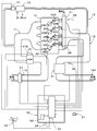
- FIGS. 1 and 2 a schematic configuration of a control system of an internal combustion engine will be described with reference to FIGS. 1 and 2.
- a four-cylinder engine 10 (for example, a diesel engine) mounted on a vehicle will be described as an example of an internal combustion engine.
- the engine 10 is connected to an intake pipe 11 for introducing intake air to each of the cylinders 45A to 45D of the engine 10. Further, the engine 10 is connected to an exhaust pipe 12 through which exhaust gas from the cylinders 45A to 45D is discharged.
- Each of the cylinders 45A-45D is provided with injectors 43A-43D connected to the common rail 41 via fuel pipes 42A-42D. Further, a flow rate detecting means 21 and an electronic throttle device 47 are provided in the intake passage of the intake pipe 11, and an exhaust temperature detecting means 62 and an exhaust purification device 61 are provided in the exhaust passage of the exhaust pipe 12. There is.
- the control device 50 includes at least a control unit 51 and a storage unit 53.
- the flow rate detection unit 21 is, for example, a flow rate sensor capable of detecting the flow rate of intake air, and is provided in the intake passage 11A.
- the control means 51 can detect an intake air flow rate which is a flow rate of intake air taken by the engine 10 based on a detection signal from the flow rate detection means 21.
- the rotation detection means 22 is, for example, a rotation angle sensor capable of detecting the number of rotations of the internal combustion engine (for example, the number of rotations of the crankshaft) and the rotation angle (for example, compression top dead center timing of each cylinder). ing.
- the control unit 51 can detect the number of rotations, the rotation angle, and the like of the engine 10 based on the detection signal from the rotation detection unit 22.
- the atmospheric pressure detection means 23 is an atmospheric pressure sensor, for example, and is provided in the control device 50.
- the control unit 51 can detect the atmospheric pressure based on the detection signal from the atmospheric pressure detection unit 23.
- the accelerator pedal depression amount detecting means 25 is, for example, an accelerator pedal depression angle sensor, and is provided on the accelerator pedal.
- the control means 51 can detect the depression amount of the accelerator pedal by the driver based on the detection signal from the accelerator pedal depression amount detection means 25.
- the electronic throttle device 47 is provided in the intake pipe 11 (intake path), and controls the throttle for adjusting the opening degree of the intake pipe 11 based on the control signal from the control means 51 to adjust the intake flow rate.
- the control means 51 is provided in the intake pipe 11 by outputting a control signal to the electronic throttle device 47 based on the detection signal from the throttle opening degree detection means 47S (for example, throttle opening degree sensor) and the target throttle opening degree. The throttle opening can be adjusted.
- the EGR path 13 communicates the exhaust pipe 12 with the intake pipe 11, and can return part of the exhaust gas in the exhaust pipe 12 to the intake pipe 11.
- the EGR valve 14 (EGR valve) is disposed on the exhaust inflow side or exhaust outflow side close to the EGR cooler 15 in the EGR path 13, and based on the control signal from the control means 51, the opening degree of the EGR path 13 Adjust the
- the EGR cooler 15 is provided in the EGR path 13, and the exhaust gas flows in from the exhaust inflow side which is the side of the exhaust pipe 12 in the EGR path 13, and from the exhaust outflow side which is the side of the intake pipe 11 in the EGR path 13 Exhaust gas is discharged. Further, coolant for cooling is supplied to the EGR cooler 15.
- the EGR cooler 15 is a so-called heat exchanger, and cools and discharges the inflowing exhaust gas using a coolant.
- Fuel is supplied to the common rail 41 from a fuel tank (not shown), and the fuel in the common rail 41 is maintained at high pressure and supplied to the injectors 43A to 43D through the fuel pipes 42A to 42D.
- the injectors 43A to 43D are provided corresponding to the respective cylinders 45A to 45D, and inject a predetermined amount of fuel into each cylinder at a predetermined timing according to a control signal from the control means 51.
- the fuel temperature detection means 28 is, for example, a fuel temperature detection sensor, and outputs a detection signal according to the temperature of the fuel in the common rail 41.
- the control unit 51 can detect the temperature of the fuel in the common rail 41 based on the detection signal from the fuel temperature detection unit 28.
- the fuel pressure detection means 29 is, for example, a fuel pressure detection sensor, and outputs a detection signal according to the pressure of the fuel in the common rail 41.
- the control means 51 can detect the pressure of the fuel in the common rail 41 based on the detection signal from the fuel pressure detection means 29.
- the vehicle speed detection means 27 is, for example, a vehicle speed detection sensor, and is provided on a wheel or the like of the vehicle.
- the control means 51 can detect the speed of the vehicle based on the detection signal from the vehicle speed detection means 27.
- the exhaust temperature detection means 62 is, for example, an exhaust temperature detection sensor, and outputs a detection signal according to the temperature of the exhaust in the exhaust pipe 12.
- the control unit 51 can detect the temperature of the exhaust in the exhaust pipe 12 based on the detection signal from the exhaust temperature detection unit 62.
- the exhaust purification device 61 is, for example, an oxidation catalyst, a DPF (Diesel Particulate Filter), a selective reduction catalyst, or the like, and removes air pollutants in the exhaust gas. Since the oxidation catalyst, the DPF, and the selective reduction catalyst are existing ones, the detailed description will be omitted.
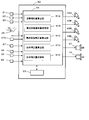
- the control unit 51 is, for example, a CPU (central processing unit), and is accommodated in the control device 50. As shown in FIG. 2, the control means 51 receives detection signals from the above-described various detection means etc., detects the operating state of the engine 10, and detects the injectors 43A to 43D, the EGR valve 14, and the electronic throttle device 47. Output a control signal to drive the Further, the control means 51 can detect the amount of fuel supplied to each of the cylinders 45A to 45D by the control signal (injection command signal) output to the injectors 43A to 43D. Further, the input to the control unit 51 and the output from the control unit 51 are not limited to the examples shown in FIGS. 1 and 2, and various detection units (cooling water temperature detection unit, NOx detection unit, etc.), various actuators ( There are various lamps etc.). The description of each part of reference numerals 51A to 51E in FIG. 2 will be described later.
- the storage unit 53 is, for example, a storage device such as a Flash-ROM, and stores a program for executing processing to be described later.
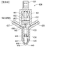
- FIG. 3 shows a cross-sectional view (schematic view) of the injector 43A at the valve closing time
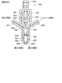
- FIG. 4 shows a cross-sectional view (schematic view) of the injector 43A at the valve opening time. Since the injectors 43A to 43D shown in FIG. 1 have the same structure, the injector 43A will be described as an example. As shown in FIGS. 3 and 4, the injector 43A has a body 431, a connector 436, an electromagnetic coil 441, a return spring 442, a control valve 443, a ball valve 444, a needle 447, a needle spring 446, a nozzle 448 and the like. There is.
- the body 431 has hollows of a suction chamber 432, a control chamber 433, and a needle chamber 434 inside, and has a high pressure fuel supply path 437, an orifice 445, and a return fuel discharge path 438.
- an electromagnetic coil 441, a return spring 442, a control valve 443 and a ball valve 444 are accommodated.
- the electromagnetic coil 441 sucks the control valve 443 upward when power is supplied from the connector 436.
- the control valve 443 is biased downward by the return spring 442.
- a ball valve 444 is attached to the lower end of the control valve 443.
- the ball valve 444 blocks the upper end of the orifice 445.
- the suction chamber 432 is in communication with the control chamber 433 at the orifice 445 and is connected to the return fuel discharge path 438.
- the control chamber 433 accommodates the upper portion of the needle 447.
- the control chamber 433 is connected to the high pressure fuel supply path 437 and is in communication with the suction chamber 432 at the orifice 445.
- the control chamber 433 is filled with the high pressure fuel supplied from the high pressure fuel supply path 437.
- the needle chamber 434 contains the lower portion of the needle 447 and a needle spring 446.
- the needle chamber 434 is connected to a return fuel discharge path 438.
- the nozzle 448 is attached to the lower end of the body 431 and has a hollow filling chamber 435 inside. Further, at a lower portion of the nozzle 448, an injection hole 449 which is a through hole for communicating the filling chamber 435 with the outside of the nozzle 448 is formed.
- the filling chamber 435 is connected to the high pressure fuel supply path 437.
- the injector 43A is closed as follows.
- the control valve 443 is biased downward by the return spring 442, and the ball valve 444 closes the upper end of the orifice 445.
- the control chamber 433 is filled with the high pressure fuel from the high pressure fuel supply path 437.
- the downward biasing force in which the upper portion of the needle 447 is biased downward by the high pressure fuel in the control chamber 433 and the upward biasing force in which the lower portion of the needle 447 is biased upward by the high pressure fuel in the filling chamber 435 are substantially
- the needle 447 is biased downward by the needle spring 446 in balance.
- the needle 447 is biased downward to close the injection hole 449, and the valve is closed.
- the nozzle 448 is formed with the injection hole 449 into which the fuel is injected.
- the needle 447 opens and closes the injection hole 449.
- the return spring 442 directly moves the control valve 443 downward, and indirectly moves the needle 447 to the closed position where the injection hole 449 is closed.
- the electromagnetic coil 441 directly moves the control valve 443 upward, and indirectly moves the needle 447 to the open position where the injection hole 449 is opened.
- the injector 43A When electric power is supplied to the electromagnetic coil 441, the injector 43A is opened as follows. When power is supplied to the electromagnetic coil 441, the control valve 443 is drawn upward by the electromagnetic coil 441, and the ball valve 444 is separated from the upper end of the orifice 445. Then, the high-pressure fuel charged in the control chamber 433 flows into the suction chamber 432 from the orifice 445, and the fuel pressure in the control chamber 433 decreases. The low-pressure fuel flowing into the suction chamber 432 is discharged from the return fuel discharge path 438. When the fuel pressure in the control chamber 433 is lowered, the high pressure fuel filled in the filling chamber 435 pushes up the needle 447, the tip of the needle 447 is separated from the injection hole 449, and the valve is opened.
- the injector 43A repeats the above valve opening and valve closing, and various wear progresses at various points. For example, wear of the return spring 442 progresses at the contact portion between the return spring 442 and the control valve 443. Further, at the contact portion with the nozzle 448, the tip of the needle 447 is worn away by the contact and the flow of high pressure fuel. At the contact portion of the inner wall of the nozzle 448 with the tip of the needle 447, wear progresses by the contact and the flow of high pressure fuel, and the inner wall of the injection hole 449 is worn by the flow of high pressure fuel It will progress. Since these wears do not progress due to the same factor, they progress differently depending on the injection state and the fuel state.
- the wear of the return spring 442 progresses according to the number of injections
- the wear of the needle 447 and the wear of the nozzle 448 progress according to the fuel injection amount of high pressure fuel and the fuel pressure.
- the wear progresses according to the fuel injection amount of the high pressure fuel and the fuel pressure.
- the injector does not wear uniformly as a whole, but different wear progresses in each part and each part. For this reason, it is preferable to select the injector component in advance and estimate the wear for each injector component as having an influence on the accuracy of the fuel injection amount from the injector.
- the injector component is considered to affect the accuracy of the fuel injection amount from the injector, and is a single component constituting the injector, and a group component composed of a plurality of related single components. , Part of a single part, or part of a group part.
- the injector 43A executes opening and closing once, the amount of wear is almost negligible. However, as valve opening and closing are repeated several thousand times and several tens of thousands times according to the rotation of the internal combustion engine, the amount of wear becomes a non-negligible amount, and the command fuel injection amount from the control device to the injector The deviation of the actual fuel injection amount from the actual injector becomes an unacceptable deviation. For this reason, it is necessary to control the shift periodically or constantly.
- the process of the flowchart shown in FIG. 5 is a method of controlling the fuel injection amount of the engine 10 (internal combustion engine) using the control device 50 (see FIGS. 1 and 2), for example, starting at every fuel injection timing from the injector. Be done.
- control device 50 starts the process shown in FIG. 5, control proceeds to step S100.
- the needle 447 (single component), the return spring 442 (single component), the nozzle 448 (single component), and the injection hole 449 (part of single component) shown in FIGS. 3 and 4 are injectors. The example selected as the configuration unit will be described.
- step S100 the control device 50 calculates a target injection amount (for example, target injection time) to be injected this time based on, for example, the current number of revolutions of the internal combustion engine and the current accelerator pedal depression amount.
- the storage means 53 stores a target injection amount map (not shown) corresponding to the number of revolutions of the internal combustion engine and the accelerator pedal depression amount
- the control means 51 see FIG. 1
- the engine speed is calculated using the engine speed, the accelerator pedal depression amount, and the target injection amount map.
- the process of step S100 corresponds to a target injection amount calculating step of calculating a target injection amount to be injected from the injector according to the operating state of the engine (internal combustion engine).
- the control means 51 executing step S100 calculates a target injection amount to be injected from the injector in accordance with the operating state of the engine (internal combustion engine). Act as.
- step S200 the control device 50 reads out the wear amount for each component corresponding to the injector to be injected this time, and based on the wear amount for each component, corrects for each injector structure corresponding to the injector to be injected this time
- the amount of correction for each component which is an amount, is calculated, and the process proceeds to step S300.
- the details of the process of step S200 will be described later.
- the wear amount for each component is stored for each injector and for each injector component.
- the process of step S200 corresponds to a component-specific correction amount calculating step of calculating the component-specific correction amount which is the correction amount of each injector component based on the component-specific wear amount of each injector component.
- the control means 51 executing step S200 respectively corrects the correction amount for each component which is the correction amount for each injector component based on the wear amount for each component for each injector component. It functions as the component-part correction amount calculation part 51C to calculate.
- step S300 the control device 50 calculates a total correction amount which is a correction amount of the entire injector to be injected this time based on the correction amount for each of the component parts for each injector component corresponding to the injector to be injected this time. Proceed with the process. The details of the process of step S300 will be described later.
- the process of step S300 corresponds to an overall correction amount calculating step of calculating an overall correction amount which is a correction amount of the entire injector based on the correction amount of each component forming unit for each injector configuration.
- the control means 51 executing step S300 calculates an overall correction amount, which is a correction amount of the entire injector, based on the correction amount of each component of each injector structure. It functions as the amount calculator 51D.
- control device 50 adds the target injection amount calculated in step S100 and the total correction amount calculated in step S300 to calculate a corrected target injection amount, and advances the process to step S500.
- the target injection "amount” is calculated as the target injection "time”
- the entire correction “amount” is calculated as the entire correction "time”. Therefore, the corrected target injection “amount” is also corrected. It is calculated as the after target injection "time”.
- step S500 the control device 50 drives the injector to be injected this time with the corrected target injection amount (corrected target injection time) as the command fuel injection amount, and advances the process to step S600.
- the injector to be injected this time opens in accordance with the corrected fuel injection amount, and injects an amount of fuel according to the corrected fuel injection amount.
- the processing of steps S400 and S500 corresponds to an overall correction amount reflecting step of injecting from the injector a corrected target injection amount obtained by correcting the target injection amount with the entire correction amount at the injection timing of the injector.
- the control means 51 executing steps S400 and S500 injects from the injector a corrected target injection amount obtained by correcting the target injection amount with the overall correction amount at the injection timing of the injector. It functions as the entire correction amount reflecting unit 51E.
- step S600 the control device 50 estimates wear amounts (current wear amounts) which are wear amounts for each of the injector constituent parts corresponding to the injector injected this time, and advances the process to step S700.
- the details of step S600 will be described later.
- the process of step S600 is an injector constituting part which is a part of the parts constituting the injector, or an injector constituting part which is selected in advance to affect the accuracy of the fuel injection amount from the injector. It corresponds to each component part wear amount estimation step for estimating each component part wear amount which is the wear amount for each component. Further, as shown in FIG.
- the control means 51 executing step S600 is an injector constituting part which is a part of a plurality of parts constituting the injector or a part of the part, and It functions as a per-component wear amount estimation unit 51B that estimates the per-component wear amount that is the wear amount for each of the injector components that is selected in advance as one that affects the accuracy.
- step S700 the control device 50 adds the wear amount of each injection from the current injection to the wear amount of each component stored in each injector structure corresponding to the injector injected this time. Add and store, and end the process. That is, the control device 50 integrates each wear amount estimated in step S600 as the wear amount for each component. The details of the process of step S700 will be described later.
- step S600 and S700 estimate of wear amount per component and integration processing
- step S610 the control device 50 acquires the fuel injection amount (the corrected target injection amount) at the time of current injection in step S500, the current (current) fuel pressure, and the current (current) fuel temperature. Further, the control device 50 substitutes the number of injections [i-1] +1 into the number of injections [i] corresponding to the injector injected this time (counts up the number of injections corresponding to the injector injected this time), The process proceeds to S620.
- step S620 the control device 50 performs the current injection in step S500 based on the fuel injection amount, the fuel pressure, the fuel temperature acquired in step S610, and the needle wear characteristics stored in the storage unit.
- the amount of wear (needle) of the needle 447 (see FIG. 3), which is one of the injector components corresponding to the injector, is determined.
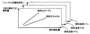
- the wear characteristics for needles shown in FIG. 8 are stored in the storage means for each fuel temperature, and the wear characteristics for each needle are as follows: the fuel injection amount on the horizontal axis and the needle (in one injection) on the vertical axis
- the amount of wear (the amount of wear of the tip of the needle 447 in contact with the nozzle 448 shown in FIG. 3, etc.) is set.
- the control device 50 selects the needle wear characteristics according to the fuel temperature, and uses the selected needle wear characteristics to determine the wear amount (needle) according to the fuel pressure and the fuel injection amount.
- control device 50 adds (accumulates) the wear amount (needle) obtained this time to the wear amount [i-1] for each component for the needle stored in the storage means corresponding to the injector injected this time And store the wear amount [i] for each new component for the needle. That is, the control device 50 substitutes “the (previous) needle component component wear amount + the (current) wear amount (needle)” ”into“ the (current) needle component component wear ”and stores By doing this, the wear amount for each of the component parts of the needle, which is the accumulated wear amount (needle) corresponding to the injector injected this time, is stored. Then, control device 50 advances the process to step S630.
- step S630 the control device 50 performs the current injection in step S500 based on the fuel injection amount, the fuel pressure, the fuel temperature acquired in step S610, and the spring wear characteristics stored in the storage unit.
- the amount of wear (spring) of the return spring 442 (see FIG. 3), which is one of the injector components corresponding to the injector, is determined.
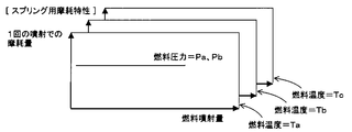
- the wear characteristics for springs shown in FIG. 9 are stored in the storage means for each fuel temperature, and the wear characteristics for each spring are the fuel injection amount on the horizontal axis and the return (in one injection) on the vertical axis.
- the amount of wear of the spring (the amount of wear of the tip of the return spring 442 in contact with the control valve 443 shown in FIG. 3, etc.) is set.
- the control device 50 selects a spring wear characteristic according to the fuel temperature, and uses the selected spring wear characteristic to obtain a wear amount (spring) according to the fuel pressure and the fuel injection amount.
- control device 50 adds (accumulates) the wear amount (spring) obtained this time to the wear amount per spring component [i-1] stored in the storage means corresponding to the injector injected this time And store the wear amount [i] for each new spring component. That is, the control device 50 substitutes "(previous) spring component wear amount + (this time) wear amount (spring)” into “the (current) spring component wear amount” and stores By doing this, the wear amount for each spring component, which is the accumulated wear amount (spring) corresponding to the injector injected this time, is stored. Then, control device 50 advances the process to step S640.
- step S640 the control device 50 performs the current injection in step S500 based on the fuel injection amount, the fuel pressure, the fuel temperature acquired in step S610, and the nozzle wear characteristics stored in the storage unit.
- the amount of wear (nozzle) of the nozzle 448 (see FIG. 3), which is one of the injector components corresponding to the injector, is determined.
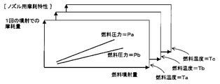
- the wear characteristics for nozzles shown in FIG. 10 are stored in the storage means for each fuel temperature, and for the wear characteristics for each nozzle, the horizontal axis is the fuel injection amount, and the vertical axis is the nozzles (in one injection) Of the nozzle 448 (such as the amount of wear of the nozzle 448 in contact with the tip of the needle 447 shown in FIG. 3).
- the control device 50 selects the nozzle wear characteristics according to the fuel temperature, and uses the selected nozzle wear characteristics to determine the wear amount (nozzle) according to the fuel pressure and the fuel injection amount.
- control device 50 adds the wear amount (nozzle) obtained this time to the wear amount per nozzle component [i-1] stored in the storage means corresponding to the injector injected this time (accumulated) And store the wear amount [i] for each new component for nozzle. That is, the control device 50 substitutes "(previous) nozzle component wear amount + (current) wear amount (nozzle)” into “the (current) nozzle component wear amount” and stores By doing this, the wear amount for each of the component parts of the nozzle, which has integrated the wear amount (nozzle) corresponding to the injector injected this time, is stored. Then, control device 50 advances the process to step S650.
- step S650 the control device 50 performs the current injection in step S500 based on the fuel injection amount, fuel pressure, fuel temperature acquired in step S610, and the wear characteristics for the injection hole stored in the storage unit.
- the wear amount (injection hole) of the injection hole 449 (see FIG. 3), which is one of the injector components corresponding to the injectors, is determined.
- the wear characteristics for injection holes shown in FIG. 11 are stored in the storage means for each fuel temperature, and for the wear characteristics for each injection hole, the horizontal axis is the fuel injection amount, and the vertical axis is (in one injection )
- the amount of wear of the injection hole (the amount of wear of the injection hole 449 shown in FIG. 3, etc.) is set.
- the control device 50 selects the wear characteristic for the injection hole according to the fuel temperature, and obtains the wear amount (injection hole) according to the fuel pressure and the fuel injection amount using the selected wear characteristic for the injection hole.
- the control device 50 adds the wear amount (injection hole) obtained this time to the wear amount [i-1] for each component for the injection hole stored in the storage means corresponding to the injector injected this time (integration ), And stores the new wear amount [i] per injection hole configuration. That is, the control device 50 substitutes “(previous) amount of wear of each (previous) injection hole component + amount of (current) wear (injection hole)” into “the (current) amount of wear of the component for the injection hole”. By storing the amount of wear, the wear amount for each of the injection hole configuration parts is calculated by integrating the wear amount (injection hole) corresponding to the injector injected this time. Then, the control device 50 returns to the bottom of step S700 in FIG. 5 and ends the processing.
- step S200 and S300 [Details of processing in steps S200 and S300 (calculation of correction amount for each component and calculation processing of total correction amount) (FIG. 7)]
- step S200 in FIG. 5 control device 50 advances the process to step S210 shown in FIG.
- step S210 the control device 50 acquires the target injection amount obtained in step S100, the current (current) fuel pressure, and the current (current) fuel temperature, and advances the process to step S220.
- step S220 the control device 50 performs the current injection based on the target fuel injection amount, fuel pressure, fuel temperature acquired in step S210, and the needle configuration part correction amount map stored in the storage unit.
- the correction amount for each needle component according to the wear amount of the needle 447 (see FIG. 3) which is one of the injector components corresponding to the injectors is calculated, and the process proceeds to step S230.
- the needle configuration unit correction amount maps M1 to M3 shown in FIG. 12 are stored in the storage unit for each fuel temperature.
- the fuel pressure fuel pressure: P1, P2
- the injection amount target injection amount: ⁇ 1, ⁇ 2.
- the correction amount (D11, D12) is set as a correction amount per unit wear amount (corresponding to a predetermined wear amount).
- the control device 50 selects the needle component part correction amount map according to the fuel temperature, and uses the selected needle component part correction amount map to determine the fuel pressure (fuel pressure) and the injection amount (target injection amount) Determine the correction amount (needle) per unit wear amount according to. Then, the control device 50 multiplies the “correction amount per unit wear amount (needle)” by “the wear amount per unit component for needle corresponding to the injector to be injected this time / the unit wear amount” to the current injection. A correction amount for each component for needle is calculated.
- step S230 the control device 50 performs the current injection based on the target fuel injection amount, fuel pressure, fuel temperature acquired in step S210, and the spring component correction amount map stored in the storage unit.
- the correction amount for each spring component according to the wear amount of the return spring 442 (see FIG. 3) which is one of the injector components corresponding to the injectors is calculated, and the process proceeds to step S240.
- a spring-use component-based correction amount map (not shown) similar to that shown in FIG. 12 is stored in the storage means for each fuel temperature.
- fuel pressure (fuel pressure) in the “row” direction and injection amount (target injection amount) in the “row” direction are set in the correction amount map for each spring component, and the correction amount corresponding to the fuel pressure and the injection amount is It is set (same as FIG. 12).
- the correction amount is set as a correction amount per unit wear amount.
- the control device 50 selects the spring component-specific correction amount map according to the fuel temperature, and uses the selected spring component-specific correction amount map to determine the fuel pressure (fuel pressure) and the injection amount (target injection amount) Determine the correction amount (spring) per unit wear amount according to.
- control device 50 multiplies the “correction amount per unit wear amount (spring)” by “the wear amount per unit spring component corresponding to the injector to be injected this time / the unit wear amount” to obtain the current injection.
- the amount of correction for each spring component is calculated.
- step S240 the control device 50 performs the current injection based on the target fuel injection amount, fuel pressure, and fuel temperature acquired in step S210, and the correction amount map for each nozzle component stored in the storage unit.
- the correction amount for each nozzle component according to the wear amount of the nozzle 448 (see FIG. 3) which is one of the injector components corresponding to the injectors is calculated, and the process proceeds to step S250.
- the same correction amount map (not shown) for each nozzle component as in FIG. 12 is stored in the storage unit for each fuel temperature.
- the fuel pressure (fuel pressure) in the “row” direction and the injection amount (target injection amount) in the “row” direction are set in the correction amount map for each nozzle component, and the correction amount corresponding to the fuel pressure and the injection amount is It is set (same as FIG. 12).
- the correction amount is set as a correction amount per unit wear amount.
- the control device 50 selects the nozzle component correction amount map according to the fuel temperature, and uses the selected nozzle component correction amount map to select the fuel pressure (fuel pressure) and the injection amount (target injection amount).
- the correction amount (nozzle) per unit wear amount is determined according to Then, the control device 50 multiplies the “correction amount per unit wear amount (nozzle)” by “the wear amount per unit component for the nozzle corresponding to the injector to be injected this time / the unit wear amount” to the current injection. A correction amount for each nozzle configuration unit is calculated.
- the control device 50 performs the current calculation based on the target fuel injection amount, fuel pressure, fuel temperature acquired at step S210, and the correction amount map for each of the nozzle hole components stored in the storage means.
- a correction amount for each of the injection hole configuration parts according to the wear amount of the injection hole 449 (see FIG. 3) which is one of the injector parts corresponding to the injector to be injected is obtained, and the process proceeds to step S260.
- a correction amount map (not shown) for each injection hole configuration part similar to that shown in FIG. 12 is stored in the storage means for each fuel temperature.
- the fuel pressure (fuel pressure) in the “row” direction and the injection amount (target injection amount) in the “row” direction are set in the correction amount map for each injection hole component, and the correction amount according to the fuel pressure and the injection amount Is set (similar to FIG. 12).
- the correction amount is set as a correction amount per unit wear amount.
- the control device 50 selects the injection hole configuration part correction amount map according to the fuel temperature, and uses the selected injection hole configuration part correction amount map to select the fuel pressure (fuel pressure) and the injection amount (target injection
- the correction amount (injection hole) per unit wear amount according to the amount) is determined.
- control device 50 multiplies the “correction amount per unit wear amount (injection hole)” by “the wear amount per unit configuration part for injection hole corresponding to the injector to be injected this time / unit wear amount” A correction amount is calculated for each injection hole configuration part with respect to the injection.
- step S260 the control device 50 adds the correction amount for each needle component, the correction amount for each spring component, the correction amount for each nozzle component, and the correction amount for each nozzle hole component.
- the entire correction amount is calculated, and the process proceeds to step S400 in FIG.
- the correction "amount" for each component is obtained as the correction "time” for each component, and the calculated overall correction “amount” is also obtained as the total correction "time”.
- the wear amount per needle component corresponding to the replaced injector, the wear amount per spring component, the wear amount per nozzle component, the configuration of the injection hole should be reset.
- a recent vehicle is provided with a connector for connecting a tool (such as a computer for vehicle diagnosis) for communicating with a control unit (control device) mounted on the vehicle. To issue a command to reset the wear amount of each component corresponding to the replaced injector.
- the accuracy of the fuel injection amount from the injector is affected by the plurality of parts constituting the injector or a part of the parts.
- the injector configuration is preselected as an effect.
- the wear amount according to each factor is suitably calculated
- the fuel injection amount control method for an internal combustion engine of the present invention is not limited to the processing, operation, and the like described in the present embodiment, and various changes, additions, and deletions can be made without departing from the scope of the present invention.
- the target control system to which the fuel injection amount control method for an internal combustion engine of the present invention is applied is not limited to that shown in the example of FIG. 1, and can be applied to various internal combustion engines.
- the invention is not limited to a diesel engine, but can be applied to a gasoline engine, is not limited to an industrial vehicle, and can be applied to a general vehicle.
- the wear amount for each component such as the wear amount for each needle component is calculated (estimated) based on the fuel injection amount, fuel pressure, and fuel temperature. It may be calculated (estimated) based on at least one of the injection amount, the number of fuel injections, the fuel pressure, and the fuel temperature.
- the wear amount for each component such as the wear amount for the component for needle is calculated by integrating the wear amount for each injection, but the wear amount this time is not integrated.
- the number of times of fuel injection, the amount of wear of this time * a coefficient according to the cumulative travel distance, etc. may be regarded as the amount of wear per component, or the amount of wear this time may be regarded as the amount of wear per component.
- target injection “amount” is target injection “time”
- correction “amount” for each component is correction "time” for each component
- overall correction “amount” is overall correction "time”, after correction
- amendment was demonstrated.
- the target injection “amount” is the target injection “time”
- the correction “amount” for each component is the correction “factor” for each component
- the entire correction “amount” is the overall correction “factor”
- the injector component is not limited to the needle, the return spring, the nozzle, the injection hole, and it is appropriate to affect the accuracy of the fuel injection amount from the injector according to the structure of the injector and the like. Parts or parts of parts are selected.
Landscapes
- Engineering & Computer Science (AREA)
- Chemical & Material Sciences (AREA)
- Combustion & Propulsion (AREA)
- Mechanical Engineering (AREA)
- General Engineering & Computer Science (AREA)
- Physics & Mathematics (AREA)
- Electromagnetism (AREA)
- Fluid Mechanics (AREA)
- Electrical Control Of Air Or Fuel Supplied To Internal-Combustion Engine (AREA)
- Combined Controls Of Internal Combustion Engines (AREA)
- Fuel-Injection Apparatus (AREA)
Abstract
インジェクタから噴射する目標噴射量を算出する目標噴射量算出ステップと、インジェクタからの燃料噴射量の精度に影響を及ぼすものとして予め選択されたインジェクタ構成部毎の構成部毎摩耗量をそれぞれ推定する構成部毎摩耗量推定ステップと、構成部毎摩耗量に基づいてインジェクタ構成部毎の構成部毎補正量をそれぞれ算出する構成部毎補正量算出ステップと、構成部毎補正量に基づいてインジェクタ全体の全体補正量を算出する全体補正量算出ステップと、目標噴射量を全体補正量にて補正した補正後目標噴射量をインジェクタから噴射する全体補正量反映ステップと、を有する。
Description
本発明は、ディーゼルエンジン等の内燃機関の燃料噴射量制御方法に関する。
近年、ディーゼルエンジン等の内燃機関では、コンピュータを用いて正確な燃料噴射量をリアルタイムに算出し、算出した燃料噴射量をインジェクタから噴射している。インジェクタは、コンピュータから指令された燃料噴射量に対して、高精度な燃料噴射量を実現しているが、経時劣化等によって、コンピュータから指令された燃料噴射量に対して、実際の燃料噴射量が徐々にズレていく傾向がある。環境保全等の観点から、この指令燃料噴射量(コンピュータからの指令値)に対する実燃料噴射量(インジェクタからの実際の噴射量)のズレを、数%以内に抑える必要がある。
例えば、特許文献1には、エンジン回転数とアクセル踏込量から目標燃料噴射量指令値Qgを算出し、インジェクタ内の燃料温度に対する補正燃料噴射量Qmを算出し、目標燃料噴射量指令値Qgに対する指令値補正係数Cgを算出し、インジェクタの劣化に対する劣化補正係数Ciを算出し、最終補正燃料噴射量Qmf=Qm*Cg*Ciを算出し、最終燃料噴射量指令値Qf=Qg+Qmfを算出する、内燃機関の燃料噴射量制御方法が開示されている。
インジェクタは高精度に加工された複数のパーツによって構成され、各パーツは、燃料温度や燃料圧力や燃料噴射量や噴射回数等、それぞれ別々の要因によって劣化状態が異なっていく。例えば、インジェクタ先端に形成された燃料の噴射口である噴孔は、燃料噴射量と燃料圧力を要因として徐々に径が大きくなるように劣化が進み、インジェクタを閉弁状態にするリターンスプリングは、噴射回数を要因として徐々に摩耗するように劣化が進んでいく。
これに対して特許文献1に記載の内燃機関の燃料噴射量制御方法では、インジェクタの劣化に対する劣化補正係数Ciを、インジェクタ内の燃料温度に基づいた第1補正係数Ciaと、内燃機関の運転積算時間に基づいた第2補正係数Cibと、から算出している。つまり、インジェクタを構成する個々のパーツのそれぞれ異なる劣化の進行に着目せず、インジェクタ全体が一様に経時劣化していくものとみなしている。これでは、例えば同じ運転積算時間であっても、インジェクタの噴射回数が異なったり燃料圧力が異なったりする可能性があるので、より正確な劣化補正係数Ciを求めることができない可能性がある。
本発明は、このような点に鑑みて創案されたものであり、インジェクタにおける燃料噴射量の精度に影響を及ぼす劣化状態をより正確に推定し、インジェクタへの指令燃料噴射量に対する実際のインジェクタからの実燃料噴射量のズレを、より抑制することができる内燃機関の燃料噴射量制御方法を提供することを課題とする。
上記課題を解決するため、本発明の第1の発明は、制御装置を用いた、内燃機関の燃料噴射量制御方法であって、前記内燃機関の運転状態に応じて、インジェクタから噴射する目標噴射量を算出する目標噴射量算出ステップと、前記インジェクタを構成している複数の部品または前記部品の一部であるインジェクタ構成部であって前記インジェクタからの燃料噴射量の精度に影響を及ぼすものとして予め選択された前記インジェクタ構成部毎の摩耗量である構成部毎摩耗量をそれぞれ推定する構成部毎摩耗量推定ステップと、前記インジェクタ構成部毎の前記構成部毎摩耗量に基づいて、前記インジェクタ構成部毎の補正量である構成部毎補正量をそれぞれ算出する構成部毎補正量算出ステップと、前記インジェクタ構成部毎の前記構成部毎補正量に基づいて、前記インジェクタ全体の補正量である全体補正量を算出する全体補正量算出ステップと、前記目標噴射量を前記全体補正量にて補正した補正後目標噴射量を前記インジェクタから噴射する全体補正量反映ステップと、を有する、内燃機関の燃料噴射量制御方法である。
次に、本発明の第2の発明は、上記第1の発明に係る内燃機関の燃料噴射量制御方法であって、前記インジェクタ構成部は、単体の部品、関連付けられた複数の単体の部品にて構成されたグループ部品、単体の部品の一部、グループ部品の一部、の少なくとも1つである、内燃機関の燃料噴射量制御方法である。
次に、本発明の第3の発明は、上記第1の発明または第2の発明に係る内燃機関の燃料噴射量制御方法であって、前記インジェクタ構成部毎の前記構成部毎摩耗量を、前記インジェクタからの燃料噴射量、前記インジェクタの燃料噴射回数、前記インジェクタに供給される燃料の圧力である燃料圧力、前記インジェクタに供給される燃料の温度である燃料温度、の少なくとも1つに基づいて推定する、内燃機関の燃料噴射量制御方法である。
次に、本発明の第4の発明は、上記第3の発明に係る内燃機関の燃料噴射量制御方法であって、前記インジェクタ構成部毎の前記構成部毎摩耗量を、前記インジェクタからの燃料噴射量、前記インジェクタの燃料噴射回数、前記インジェクタに供給される燃料の圧力である燃料圧力、前記インジェクタに供給される燃料の温度である燃料温度、の少なくとも1つに基づいて推定した噴射毎の摩耗量である噴射毎摩耗量を積算して推定する、内燃機関の燃料噴射量制御方法である。
次に、本発明の第5の発明は、上記第4の発明に係る内燃機関の燃料噴射量制御方法であって、前記インジェクタが交換された場合、交換された前記インジェクタに対して積算されているそれぞれの前記構成部毎摩耗量をリセットする、内燃機関の燃料噴射量制御方法である。
次に、本発明の第6の発明は、上記第1の発明~第5の発明のいずれか1つに係る内燃機関の燃料噴射量制御方法であって、前記構成部毎補正量を、前記インジェクタ構成部の前記構成部毎摩耗量と、前記インジェクタ構成部毎に設定されて、燃料噴射量と燃料圧力に対応させて所定の摩耗量に応じた補正量が設定された構成部毎補正量マップと、に基づいて算出する、内燃機関の燃料噴射量制御方法である。
次に、本発明の第7の発明は、上記第1の発明~第6の発明のいずれか1つに係る内燃機関の燃料噴射量制御方法であって、前記目標噴射量は、目標噴射時間であり、前記構成部毎補正量は、構成部毎補正時間であり、前記全体補正量は、各構成部毎補正量である各構成部毎補正時間の総和である全体補正時間であり、前記補正後目標噴射量は、目標噴射時間に全体補正時間が加算された補正後目標噴射時間である、内燃機関の燃料噴射量制御方法である。
次に、本発明の第8の発明は、上記第1の発明~第7の発明のいずれか1つに係る内燃機関の燃料噴射量制御方法であって、前記インジェクタは、燃料が噴射される噴孔が形成されたノズルと、前記噴孔を開閉するニードルと、前記噴孔を閉状態とする閉位置に前記ニードルを移動させるリターンスプリングと、前記噴孔を開状態とする開位置に前記ニードルを移動させる電磁コイルと、を有しており、前記インジェクタ構成部は、前記噴孔、前記ノズル、前記ニードル、前記リターンスプリング、の少なくとも1つである、内燃機関の燃料噴射量制御方法である。
第1の発明によれば、インジェクタ全体が一様に経時劣化していくものとみなさず、インジェクタを複数のインジェクタ構成部に分解(仮想的に分解)して考え、インジェクタ構成部毎の摩耗量である構成部毎摩耗量を推定する。つまり、インジェクタ構成部毎に劣化状態が異なるので、インジェクタ構成部毎に劣化状態を推定する。そしてインジェクタ構成部毎の構成部毎補正量を算出して、全体補正量を算出する。これにより、インジェクタの劣化状態(燃料噴射量の精度に影響を及ぼす劣化状態)をより正確に推定することができるので、インジェクタへの指令燃料噴射量に対する実際のインジェクタからの実燃料噴射量のズレを、より抑制することができる。
第2の発明によれば、燃料噴射量の精度に影響を及ぼすものとして複数のインジェクタ構成部に分解して考える際、インジェクタ構成部を、単体の部品、複数の単体の部品にて構成されたグループ部品、単体の部品の一部、グループ部品の一部、の少なくとも1つとして考える。これにより、異なる要因で劣化状態が変化するインジェクタ構成部を、適切に設定することができる。
第3の発明では、インジェクタ構成部毎に異なる摩耗の要因に応じて、当該インジェクタ構成部毎の構成部毎摩耗量を、より適切かつより正確に推定することができる。
第4の発明では、第3の発明にて推定した構成部毎摩耗量を積算して推定することで、インジェクタ構成部毎の構成部毎摩耗量を、さらに正確に推定することができる。
第5の発明によれば、インジェクタが交換された場合は、新たに構成部毎摩耗量の推定を開始するべきであるので、交換されたインジェクタに対する構成部毎摩耗量をリセットする。近年の車両には、車両に搭載されているコントロールユニット(制御装置)と通信するためのツール(車両診断用コンピュータ等)を接続するためのコネクタが用意されているので、例えば、当該コネクタにツールを接続して構成部毎摩耗量をリセットするコマンドを発行すればよい。
第6の発明によれば、インジェクタ構成部毎の構成部毎摩耗量から、インジェクタ構成部毎の構成部毎補正量を適切に算出することができる。
第7の発明によれば、目標噴射「量」、構成部毎補正「量」、全体補正「量」、補正後目標噴射「量」を、それぞれ「時間」という物理量として求めることで、実現が容易となる。
第8の発明によれば、インジェクタからの燃料噴射量の精度に影響を及ぼすものとしての複数のインジェクタ構成部の選択を、適切に行うことができる。
●[内燃機関の制御システムの概略構成(図1)と、制御装置50の入出力(図2)]
以下に本発明を実施するための形態を図面を用いて説明する。まず図1及び図2を用いて、内燃機関の制御システムの概略構成について説明する。本実施の形態の説明では、内燃機関の例として、車両に搭載された4気筒のエンジン10(例えばディーゼルエンジン)を用いて説明する。エンジン10には、エンジン10の各気筒45A~45Dへの吸入空気を導入する吸気管11が接続されている。またエンジン10には、各気筒45A~45Dからの排気ガスが吐出される排気管12が接続されている。各気筒45A~45Dには、燃料配管42A~42Dを介してコモンレール41に接続されたインジェクタ43A~43Dが設けられている。また吸気管11の吸気経路には、流量検出手段21、電子スロットル装置47等が設けられており、排気管12の排気経路には、排気温度検出手段62、排気浄化装置61等が設けられている。制御装置50は、少なくとも、制御手段51、記憶手段53を有している。
以下に本発明を実施するための形態を図面を用いて説明する。まず図1及び図2を用いて、内燃機関の制御システムの概略構成について説明する。本実施の形態の説明では、内燃機関の例として、車両に搭載された4気筒のエンジン10(例えばディーゼルエンジン)を用いて説明する。エンジン10には、エンジン10の各気筒45A~45Dへの吸入空気を導入する吸気管11が接続されている。またエンジン10には、各気筒45A~45Dからの排気ガスが吐出される排気管12が接続されている。各気筒45A~45Dには、燃料配管42A~42Dを介してコモンレール41に接続されたインジェクタ43A~43Dが設けられている。また吸気管11の吸気経路には、流量検出手段21、電子スロットル装置47等が設けられており、排気管12の排気経路には、排気温度検出手段62、排気浄化装置61等が設けられている。制御装置50は、少なくとも、制御手段51、記憶手段53を有している。
流量検出手段21は、例えば吸入空気の流量を検出可能な流量センサであり、吸気通路11Aに設けられている。制御手段51は、流量検出手段21からの検出信号に基づいて、エンジン10が吸入した吸入空気の流量である吸入空気流量を検出することが可能である。
回転検出手段22は、例えば内燃機関の回転数(例えばクランク軸の回転数)や回転角度(例えば各気筒の圧縮上死点タイミング)等を検出可能な回転角度センサであり、エンジン10に設けられている。制御手段51は、回転検出手段22からの検出信号に基づいて、エンジン10の回転数や回転角度等を検出することが可能である。
大気圧検出手段23は、例えば大気圧センサであり、制御装置50に設けられている。制御手段51は、大気圧検出手段23からの検出信号に基づいて、大気圧を検出することが可能である。
アクセルペダル踏込量検出手段25は、例えばアクセルペダル踏込角度センサであり、アクセルペダルに設けられている。制御手段51は、アクセルペダル踏込量検出手段25からの検出信号に基づいて、運転者によるアクセルペダルの踏込量を検出することが可能である。
電子スロットル装置47は、吸気管11(吸気経路)に設けられており、制御手段51からの制御信号に基づいて吸気管11の開度を調整するスロットルを制御し、吸気流量を調整可能である。制御手段51は、スロットル開度検出手段47S(例えば、スロットル開度センサ)からの検出信号と目標スロットル開度に基づいて、電子スロットル装置47に制御信号を出力して吸気管11に設けられたスロットルの開度を調整可能である。
EGR経路13は、排気管12と吸気管11とを連通し、排気管12内の排気ガスの一部を吸気管11に還流させることが可能である。
EGR弁14(EGRバルブ)は、EGR経路13におけるEGRクーラ15に近接する排気流入側または排気流出側に配設されており、制御手段51からの制御信号に基づいて、EGR経路13の開度を調整する。
EGRクーラ15は、EGR経路13に設けられており、EGR経路13における排気管12の側である排気流入側から排気ガスが流入され、EGR経路13における吸気管11の側である排気流出側から排気ガスを吐出する。またEGRクーラ15には、冷却用のクーラントが供給されている。EGRクーラ15は、いわゆる熱交換機であり、クーラントを用いて、流入された排気ガスを冷却して吐出する。
コモンレール41には燃料タンク(図示省略)から燃料が供給され、コモンレール41内の燃料は高圧に維持されて燃料配管42A~42Dを介してインジェクタ43A~43Dのそれぞれに供給されている。インジェクタ43A~43Dは、各気筒45A~45Dに対応させて設けられており、制御手段51からの制御信号によって各気筒内に所定のタイミングで所定量の燃料を噴射する。
燃料温度検出手段28は、例えば燃料温度検出センサであり、コモンレール41内の燃料の温度に応じた検出信号を出力する。制御手段51は、燃料温度検出手段28からの検出信号に基づいて、コモンレール41内の燃料の温度を検出可能である。
燃料圧力検出手段29は、例えば燃料圧力検出センサであり、コモンレール41内の燃料の圧力に応じた検出信号を出力する。制御手段51は、燃料圧力検出手段29からの検出信号に基づいて、コモンレール41内の燃料の圧力を検出可能である。
車速検出手段27は、例えば車両速度検出センサであり、車両の車輪等に設けられている。制御手段51は、車速検出手段27からの検出信号に基づいて、車両の速度を検出可能である。
排気温度検出手段62は、例えば排気温度検出センサであり、排気管12内の排気の温度に応じた検出信号を出力する。制御手段51は、排気温度検出手段62からの検出信号に基づいて、排気管12内の排気の温度を検出可能である。
排気浄化装置61は、例えば、酸化触媒、DPF(Diesel Particulate Filter)、選択式還元触媒等であり、排気ガス中の大気汚染物質を除去する。なお、酸化触媒、DPF、選択式還元触媒は既存のものであるので、詳細な説明は省略する。
制御手段51は、例えばCPU(中央処理ユニット)であり、制御装置50内に収容されている。制御手段51は、図2に示すように、上述した各種の検出手段等からの検出信号が入力されて、エンジン10の運転状態を検出し、インジェクタ43A~43D、EGR弁14、電子スロットル装置47を駆動する制御信号を出力する。また制御手段51は、自身がインジェクタ43A~43Dに出力した制御信号(噴射指令信号)によって、各気筒45A~45Dに供給した燃料量を検出することが可能である。また制御手段51への入力、及び制御手段51からの出力は、図1及び図2の例に限定されず、種々の検出手段(冷却水温度検出手段、NOx検出手段等)、種々のアクチュエータ(各種ランプ等)が有る。なお図2中における符号51A~51Eの各部の説明については後述する。
記憶手段53は、例えばFlash-ROM等の記憶装置であり、後述する処理を実行するためのプログラム等が記憶されている。
●[インジェクタの構造と、インジェクタ構成部の選択(図3、図4)]
図3は閉弁時におけるインジェクタ43Aの断面図(模式図)を示し、図4は開弁時におけるインジェクタ43Aの断面図(模式図)を示している。なお、図1に示すインジェクタ43A~43Dは同一の構造であるので、インジェクタ43Aを例として説明する。図3及び図4に示すように、インジェクタ43Aは、ボディ431、コネクタ436、電磁コイル441、リターンスプリング442、制御弁443、ボール弁444、ニードル447、ニードルスプリング446、ノズル448等を有している。
図3は閉弁時におけるインジェクタ43Aの断面図(模式図)を示し、図4は開弁時におけるインジェクタ43Aの断面図(模式図)を示している。なお、図1に示すインジェクタ43A~43Dは同一の構造であるので、インジェクタ43Aを例として説明する。図3及び図4に示すように、インジェクタ43Aは、ボディ431、コネクタ436、電磁コイル441、リターンスプリング442、制御弁443、ボール弁444、ニードル447、ニードルスプリング446、ノズル448等を有している。
ボディ431は、内部に、吸引室432、制御室433、ニードル室434、の各空洞部を有し、高圧燃料供給経路437、オリフィス445、リターン燃料排出経路438を有している。
吸引室432には、電磁コイル441、リターンスプリング442、制御弁443、ボール弁444、が収容されている。電磁コイル441は、コネクタ436から電力が供給されると、制御弁443を上方に吸引する。電磁コイル441への電力の供給が停止されると、制御弁443はリターンスプリング442にて下方に付勢される。制御弁443の下端にはボール弁444が取り付けられており、制御弁443の位置が下端位置の場合、ボール弁444はオリフィス445の上端を塞いでいる。また、吸引室432は、オリフィス445にて制御室433と連通されており、リターン燃料排出経路438と接続されている。
制御室433には、ニードル447の上部が収容されている。制御室433は、高圧燃料供給経路437に接続され、オリフィス445にて吸引室432と連通されている。なお、オリフィス445の上端がボール弁444で塞がれている場合、制御室433には、高圧燃料供給経路437から供給された高圧燃料が充填される。
ニードル室434には、ニードル447の下部と、ニードルスプリング446が収容されている。ニードル室434は、リターン燃料排出経路438が接続されている。
ノズル448は、ボディ431の下端に取り付けられており、空洞部とされた充填室435を内部に有している。またノズル448の下部には、充填室435とノズル448の外部とを連通する貫通孔である噴孔449が形成されている。充填室435は、高圧燃料供給経路437と接続されている。
電磁コイル441への電力の供給が停止されている場合、インジェクタ43Aは、以下のように閉弁状態となる。電磁コイル441への電力の供給が停止されている場合、制御弁443はリターンスプリング442にて下方に付勢され、ボール弁444がオリフィス445の上端を塞ぐ。すると、制御室433には、高圧燃料供給経路437からの高圧燃料が充填される。ニードル447の上方が制御室433内の高圧燃料で下方に付勢される下方付勢力と、ニードル447の下方が充填室435内の高圧燃料で上方に付勢される上方付勢力と、はほぼ釣り合い、ニードル447はニードルスプリング446にて下方に付勢される。以上より、電磁コイル441への電力の供給が停止されている場合、ニードル447は下方に付勢されて噴孔449を塞ぐので、閉弁状態となる。
以上に説明したように、ノズル448には、燃料が噴射される噴孔449が形成されている。またニードル447は、噴孔449を開閉する。またリターンスプリング442は、制御弁443を直接的に下方に移動させ、噴孔449を閉状態とする閉位置にニードル447を間接的に移動させる。また電磁コイル441は、制御弁443を直接的に上方に移動させ、噴孔449を開状態とする開位置にニードル447を間接的に移動させる。
電磁コイル441へ電力が供給されている場合、インジェクタ43Aは、以下のように開弁状態となる。電磁コイル441へ電力が供給されている場合、制御弁443は電磁コイル441にて上方に吸引され、ボール弁444がオリフィス445の上端から離間する。すると、制御室433内に充填されていた高圧燃料が、オリフィス445から吸引室432内に流れ込み、制御室433内の燃料圧力が低下する。なお、吸引室432内に流れ込んだ低圧燃料は、リターン燃料排出経路438から排出される。制御室433内の燃料圧力が低下すると、充填室435内に充填されている高圧燃料がニードル447を押し上げ、ニードル447の先端が噴孔449から離間して、開弁状態となる。
インジェクタ43Aは、上記の開弁と閉弁を繰り返し、種々の個所で、種々の摩耗が進行していく。例えば、リターンスプリング442と制御弁443との接触部でリターンスプリング442の摩耗が進行する。また、ニードル447の先端は、ノズル448との接触部にて、接触と高圧燃料の流れによって摩耗が進行する。またノズル448の内壁における噴孔449の周囲は、ニードル447の先端との接触部にて、接触と高圧燃料の流れによって摩耗が進行し、噴孔449の内壁は、高圧燃料の流れによって摩耗が進行していく。これらの摩耗は、同一の要因で進行している訳ではないので、噴射状態や燃料状態に応じて、それぞれ異なる進行をする。例えば、リターンスプリング442の摩耗は、噴射回数に応じて摩耗が進行し、ニードル447の摩耗やノズル448の摩耗は、高圧燃料の燃料噴射量と燃料圧力に応じて摩耗が進行し、噴孔449の摩耗は、高圧燃料の燃料噴射量と燃料圧力に応じて摩耗が進行していく。
従って、インジェクタは、全体が一様に摩耗していくのではなく、各部品や各部で、それぞれ異なる摩耗が進行していく。このため、インジェクタからの燃料噴射量の精度に影響を及ぼすものとして、インジェクタ構成部を予め選択して、インジェクタ構成部毎に摩耗を推定していくことが好ましい。インジェクタ構成部は、インジェクタからの燃料噴射量の精度に影響を及ぼすものとして考えられるものであり、インジェクタを構成している単体の部品、関連付けられた複数の単体の部品にて構成されたグループ部品、単体の部品の一部、グループ部品の一部、の少なくとも1つである。本実施の形態では、図3及び図4に示すニードル447(単体部品)、リターンスプリング442(単体部品)、ノズル448(単体部品)、噴孔449(単体部品の一部)、をインジェクタ構成部として選択した例にて説明する。
インジェクタ43Aが開弁と閉弁を1回実行しただけでは、摩耗量はほとんど無視できるレベルの量である。しかし、内燃機関の回転に応じて数千回、数万回と、開弁と閉弁を繰り返していくにしたがって、摩耗量は無視できない量となり、制御装置からのインジェクタへの指令燃料噴射量に対する実際のインジェクタからの実燃料噴射量のズレが、許容できないズレとなっていく。このため、定期的または定常的に、ズレを抑制する制御が必要である。
近年の一般車両では、停止前の燃料カット中の惰性走行時(ニュートラル状態での惰性走行時)において、所定量の燃料をスポット的に噴射した際の内燃機関のトルク変動量から、上記のズレ量を、定期的に学習する制御を行っているものが有る。しかし、産業車両では、この方法を利用することが困難である。以下に説明する本実施の形態の内燃機関の燃料噴射量制御方法では、特に産業車両に対して有効であり(一般車両にも有効)、定常的に上記のズレ量を抑制する。
●[制御手段51の処理手順(図5)]
以下、図5に示すフローチャートの各ステップの処理を説明する。図5に示すフローチャートの処理は、制御装置50(図1、図2参照)を用いた、エンジン10(内燃機関)の燃料噴射量制御方法であり、例えば、インジェクタからの燃料噴射タイミング毎に起動される。制御装置50は、図5に示す処理を起動すると、ステップS100へと処理を進める。なお、本実施の形態では、図3及び図4に示すニードル447(単体部品)、リターンスプリング442(単体部品)、ノズル448(単体部品)、噴孔449(単体部品の一部)、をインジェクタ構成部として選択した例にて説明する。
以下、図5に示すフローチャートの各ステップの処理を説明する。図5に示すフローチャートの処理は、制御装置50(図1、図2参照)を用いた、エンジン10(内燃機関)の燃料噴射量制御方法であり、例えば、インジェクタからの燃料噴射タイミング毎に起動される。制御装置50は、図5に示す処理を起動すると、ステップS100へと処理を進める。なお、本実施の形態では、図3及び図4に示すニードル447(単体部品)、リターンスプリング442(単体部品)、ノズル448(単体部品)、噴孔449(単体部品の一部)、をインジェクタ構成部として選択した例にて説明する。
ステップS100にて制御装置50は、例えば現在の内燃機関の回転数と、現在のアクセルペダル踏込量と、に基づいて、今回噴射する目標噴射量(例えば目標噴射時間)を算出して、ステップS200へ処理を進める。例えば記憶手段53(図1参照)には、内燃機関の回転数とアクセルペダル踏込量に応じた目標噴射量マップ(図示省略)が記憶されており、制御手段51(図1参照)が、内燃機関の回転数と、アクセルペダル踏込量と、目標噴射量マップと、を用いて算出する。ステップS100の処理は、エンジン(内燃機関)の運転状態に応じて、インジェクタから噴射する目標噴射量を算出する、目標噴射量算出ステップに相当する。また図2に示すように、ステップS100を実行している制御手段51は、エンジン(内燃機関)の運転状態に応じて、インジェクタから噴射する目標噴射量を算出する、目標噴射量算出部部51Aとして機能する。
ステップS200にて制御装置50は、今回噴射するインジェクタに対応するそれぞれの構成部品毎摩耗量を読み出し、それぞれの構成部毎摩耗量に基づいて、今回噴射するインジェクタに対応するインジェクタ構成部毎の補正量である構成部毎補正量をそれぞれ算出し、ステップS300へ処理を進める。なお、ステップS200の処理の詳細については後述する。構成部毎摩耗量は、インジェクタ毎、かつ、インジェクタ構成部毎、に記憶されている。ステップS200の処理は、インジェクタ構成部毎の構成部毎摩耗量に基づいて、インジェクタ構成部毎の補正量である構成部毎補正量をそれぞれ算出する、構成部毎補正量算出ステップに相当する。また図2に示すように、ステップS200を実行している制御手段51は、インジェクタ構成部毎の構成部毎摩耗量に基づいて、インジェクタ構成部毎の補正量である構成部毎補正量をそれぞれ算出する、構成部毎補正量算出部51Cとして機能する。
ステップS300にて制御装置50は、今回噴射するインジェクタに対応するインジェクタ構成部毎の構成部毎補正量に基づいて、今回噴射するインジェクタ全体の補正量である全体補正量を算出し、ステップS400へ処理を進める。なお、ステップS300の処理の詳細については後述する。ステップS300の処理は、インジェクタ構成部毎の構成部毎補正量に基づいて、インジェクタ全体の補正量である全体補正量を算出する、全体補正量算出ステップに相当する。また図2に示すように、ステップS300を実行している制御手段51は、インジェクタ構成部毎の構成部毎補正量に基づいて、インジェクタ全体の補正量である全体補正量を算出する、全体補正量算出部51Dとして機能する。
ステップS400にて制御装置50は、ステップS100にて算出した目標噴射量と、ステップS300にて算出した全体補正量と、を加算して補正後目標噴射量を算出し、ステップS500へ処理を進める。なお、本実施の形態では、目標噴射「量」を目標噴射「時間」として算出し、全体補正「量」を全体補正「時間」として算出しているので、補正後目標噴射「量」も補正後目標噴射「時間」として算出される。
ステップS500にて制御装置50は、補正後目標噴射量(補正後目標噴射時間)を指令燃料噴射量として、今回噴射するインジェクタを駆動して、ステップS600へ処理を進める。今回噴射するインジェクタは、補正後燃料噴射量に応じて開弁し、補正後燃料噴射量に応じた量の燃料を噴射する。ステップS400、S500の処理は、インジェクタの噴射タイミングにおいて、目標噴射量を全体補正量にて補正した補正後目標噴射量をインジェクタから噴射する、全体補正量反映ステップに相当する。また図2に示すように、ステップS400、S500を実行している制御手段51は、インジェクタの噴射タイミングにおいて、目標噴射量を全体補正量にて補正した補正後目標噴射量をインジェクタから噴射する、全体補正量反映部51Eとして機能する。
ステップS600にて制御装置50は、今回噴射したインジェクタに対応するインジェクタ構成部毎の摩耗量である摩耗量(今回の摩耗量)をそれぞれ推定し、ステップS700へ処理を進める。なお、ステップS600の詳細については後述する。ステップS600の処理は、インジェクタを構成している複数の部品または当該部品の一部であるインジェクタ構成部であってインジェクタからの燃料噴射量の精度に影響を及ぼすものとして予め選択されたインジェクタ構成部毎の摩耗量である構成部毎摩耗量をそれぞれ推定する、構成部毎摩耗量推定ステップに相当する。また図2に示すように、ステップS600を実行している制御手段51は、インジェクタを構成している複数の部品または当該部品の一部であるインジェクタ構成部であってインジェクタからの燃料噴射量の精度に影響を及ぼすものとして予め選択されたインジェクタ構成部毎の摩耗量である構成部毎摩耗量をそれぞれ推定する、構成部毎摩耗量推定部51Bとして機能する。
ステップS700にて制御装置50は、今回噴射したインジェクタに対応するインジェクタ構成部毎に記憶しているそれぞれの構成部毎摩耗量に、ステップS600にて推定した、今回の噴射によるそれぞれの摩耗量を加算して記憶し、処理を終了する。つまり、制御装置50は、ステップS600にて推定したそれぞれの摩耗量を、それぞれの構成部毎摩耗量として積算していく。なお、ステップS700の処理の詳細については後述する。
●[ステップS600、S700の処理(構成部毎摩耗量の推定と積算処理)の詳細(図6)]
次に図6を用いて、図5に示したステップS600とステップS700の処理の詳細について説明する。図5のステップS600にて制御装置50は、図6に示すステップS610へ処理を進める。
次に図6を用いて、図5に示したステップS600とステップS700の処理の詳細について説明する。図5のステップS600にて制御装置50は、図6に示すステップS610へ処理を進める。
ステップS610にて制御装置50は、ステップS500にて今回噴射した際の燃料噴射量(補正後目標噴射量)、今回の(現在の)燃料圧力、今回の(現在の)燃料温度を取得する。また制御装置50は、今回噴射したインジェクタに対応する噴射回数[i]に、噴射回数[i-1]+1を代入して(今回噴射したインジェクタに対応する噴射回数をカウントアップして)、ステップS620へ処理を進める。
ステップS620にて制御装置50は、ステップS610にて取得した燃料噴射量、燃料圧力、燃料温度と、記憶手段に記憶されているニードル用摩耗特性と、に基づいて、ステップS500にて今回噴射したインジェクタに対応するインジェクタ構成部の1つであるニードル447(図3参照)の摩耗量(ニードル)を求める。例えば、図8に示すニードル用摩耗特性が、燃料温度毎に記憶手段に記憶されており、各ニードル用摩耗特性は、横軸が燃料噴射量、縦軸が(1回の噴射での)ニードルの摩耗量(図3に示すノズル448と接触するニードル447の先端の摩耗量等)に設定されている。例えば制御装置50は、燃料温度に応じたニードル用摩耗特性を選択し、選択したニードル用摩耗特性を用いて、燃料圧力と燃料噴射量に応じた摩耗量(ニードル)を求める。
そして制御装置50は、今回噴射したインジェクタに対応させて記憶手段に記憶しているニードル用構成部毎摩耗量[i-1]に、今回求めた摩耗量(ニードル)を加算した(積算した)、新たなニードル用構成部毎摩耗量[i]を記憶する。つまり、制御装置50は、「(今回の)ニードル用構成部毎摩耗量」に、「(前回の)ニードル用構成部毎摩耗量+(今回の)摩耗量(ニードル)」を代入して記憶することで、今回噴射したインジェクタに対応する摩耗量(ニードル)を積算したニードル用構成部毎摩耗量を記憶する。そして制御装置50は、ステップS630へ処理を進める。
ステップS630にて制御装置50は、ステップS610にて取得した燃料噴射量、燃料圧力、燃料温度と、記憶手段に記憶されているスプリング用摩耗特性と、に基づいて、ステップS500にて今回噴射したインジェクタに対応するインジェクタ構成部の1つであるリターンスプリング442(図3参照)の摩耗量(スプリング)を求める。例えば、図9に示すスプリング用摩耗特性が、燃料温度毎に記憶手段に記憶されており、各スプリング用摩耗特性は、横軸が燃料噴射量、縦軸が(1回の噴射での)リターンスプリングの摩耗量(図3に示す制御弁443と接触するリターンスプリング442の先端の摩耗量等)に設定されている。例えば制御装置50は、燃料温度に応じたスプリング用摩耗特性を選択し、選択したスプリング用摩耗特性を用いて、燃料圧力と燃料噴射量に応じた摩耗量(スプリング)を求める。
そして制御装置50は、今回噴射したインジェクタに対応させて記憶手段に記憶しているスプリング用構成部毎摩耗量[i-1]に、今回求めた摩耗量(スプリング)を加算した(積算した)、新たなスプリング用構成部毎摩耗量[i]を記憶する。つまり、制御装置50は、「(今回の)スプリング用構成部毎摩耗量」に、「(前回の)スプリング用構成部毎摩耗量+(今回の)摩耗量(スプリング)」を代入して記憶することで、今回噴射したインジェクタに対応する摩耗量(スプリング)を積算したスプリング用構成部毎摩耗量を記憶する。そして制御装置50は、ステップS640へ処理を進める。
ステップS640にて制御装置50は、ステップS610にて取得した燃料噴射量、燃料圧力、燃料温度と、記憶手段に記憶されているノズル用摩耗特性と、に基づいて、ステップS500にて今回噴射したインジェクタに対応するインジェクタ構成部の1つであるノズル448(図3参照)の摩耗量(ノズル)を求める。例えば、図10に示すノズル用摩耗特性が、燃料温度毎に記憶手段に記憶されており、各ノズル用摩耗特性は、横軸が燃料噴射量、縦軸が(1回の噴射での)ノズルの摩耗量(図3に示すニードル447の先端と接触するノズル448の摩耗量等)に設定されている。例えば制御装置50は、燃料温度に応じたノズル用摩耗特性を選択し、選択したノズル用摩耗特性を用いて、燃料圧力と燃料噴射量に応じた摩耗量(ノズル)を求める。
そして制御装置50は、今回噴射したインジェクタに対応させて記憶手段に記憶しているノズル用構成部毎摩耗量[i-1]に、今回求めた摩耗量(ノズル)を加算した(積算した)、新たなノズル用構成部毎摩耗量[i]を記憶する。つまり、制御装置50は、「(今回の)ノズル用構成部毎摩耗量」に、「(前回の)ノズル用構成部毎摩耗量+(今回の)摩耗量(ノズル)」を代入して記憶することで、今回噴射したインジェクタに対応する摩耗量(ノズル)を積算したノズル用構成部毎摩耗量を記憶する。そして制御装置50は、ステップS650へ処理を進める。
ステップS650にて制御装置50は、ステップS610にて取得した燃料噴射量、燃料圧力、燃料温度と、記憶手段に記憶されている噴孔用摩耗特性と、に基づいて、ステップS500にて今回噴射したインジェクタに対応するインジェクタ構成部の1つである噴孔449(図3参照)の摩耗量(噴孔)を求める。例えば、図11に示す噴孔用摩耗特性が、燃料温度毎に記憶手段に記憶されており、各噴孔用摩耗特性は、横軸が燃料噴射量、縦軸が(1回の噴射での)噴孔の摩耗量(図3に示す噴孔449の摩耗量等)に設定されている。例えば制御装置50は、燃料温度に応じた噴孔用摩耗特性を選択し、選択した噴孔用摩耗特性を用いて、燃料圧力と燃料噴射量に応じた摩耗量(噴孔)を求める。
そして制御装置50は、今回噴射したインジェクタに対応させて記憶手段に記憶している噴孔用構成部毎摩耗量[i-1]に、今回求めた摩耗量(噴孔)を加算した(積算した)、新たな噴孔用構成部毎摩耗量[i]を記憶する。つまり、制御装置50は、「(今回の)噴孔用構成部毎摩耗量」に、「(前回の)噴孔用構成部毎摩耗量+(今回の)摩耗量(噴孔)」を代入して記憶することで、今回噴射したインジェクタに対応する摩耗量(噴孔)を積算した噴孔用構成部毎摩耗量を記憶する。そして制御装置50は、図5のステップS700の下に戻り、処理を終了する。
●[ステップS200、S300の処理(構成部毎補正量の算出と全体補正量の算出処理)の詳細(図7)]
次に図7を用いて、図5に示したステップS200とステップS300の処理の詳細について説明する。図5のステップS200にて制御装置50は、図7に示すステップS210へ処理を進める。
次に図7を用いて、図5に示したステップS200とステップS300の処理の詳細について説明する。図5のステップS200にて制御装置50は、図7に示すステップS210へ処理を進める。
ステップS210にて制御装置50は、ステップS100にて求めた目標噴射量と、今回の(現在の)燃料圧力、今回の(現在の)燃料温度を取得して、ステップS220へ処理を進める。
ステップS220にて制御装置50は、ステップS210にて取得した目標燃料噴射量、燃料圧力、燃料温度と、記憶手段に記憶されているニードル用構成部毎補正量マップと、に基づいて、今回噴射するインジェクタに対応するインジェクタ構成部の1つであるニードル447(図3参照)の摩耗量に応じたニードル用構成部毎補正量を求め、ステップS230へ処理を進める。例えば、図12に示すニードル用構成部毎補正量マップM1~M3が、燃料温度毎に記憶手段に記憶されている。例えば各ニードル用構成部毎補正量マップM1~M3には、「行」方向に燃圧(燃料圧力:P1、P2・・)、「列」方向に噴射量(目標噴射量:τ1、τ2・・)が設定され、燃圧と噴射量に応じた補正量(D11、D12・・)が設定されている。なお、補正量(D11、D12・・)は、単位摩耗量(所定の摩耗量に対応)あたりの補正量として設定されている。例えば制御装置50は、燃料温度に応じたニードル用構成部毎補正量マップを選択し、選択したニードル用構成部毎補正量マップを用いて、燃圧(燃料圧力)と噴射量(目標噴射量)に応じた、単位摩耗量あたりの補正量(ニードル)を求める。そして制御装置50は、求めた「単位摩耗量あたりの補正量(ニードル)」に、「今回噴射するインジェクタに対応するニードル用構成部毎摩耗量/単位摩耗量」を乗じて、今回の噴射に対するニードル用構成部毎補正量を算出する。
ステップS230にて制御装置50は、ステップS210にて取得した目標燃料噴射量、燃料圧力、燃料温度と、記憶手段に記憶されているスプリング用構成部毎補正量マップと、に基づいて、今回噴射するインジェクタに対応するインジェクタ構成部の1つであるリターンスプリング442(図3参照)の摩耗量に応じたスプリング用構成部毎補正量を求め、ステップS240へ処理を進める。例えば、図12と同様のスプリング用構成部毎補正量マップ(図示省略)が、燃料温度毎に記憶手段に記憶されている。例えば各スプリング用構成部毎補正量マップには、「行」方向に燃圧(燃料圧力)、「列」方向に噴射量(目標噴射量)が設定され、燃圧と噴射量に応じた補正量が設定されている(図12と同様)。なお、補正量は、単位摩耗量あたりの補正量として設定されている。例えば制御装置50は、燃料温度に応じたスプリング用構成部毎補正量マップを選択し、選択したスプリング用構成部毎補正量マップを用いて、燃圧(燃料圧力)と噴射量(目標噴射量)に応じた、単位摩耗量あたりの補正量(スプリング)を求める。そして制御装置50は、求めた「単位摩耗量あたりの補正量(スプリング)」に、「今回噴射するインジェクタに対応するスプリング用構成部毎摩耗量/単位摩耗量」を乗じて、今回の噴射に対するスプリング用構成部毎補正量を算出する。
ステップS240にて制御装置50は、ステップS210にて取得した目標燃料噴射量、燃料圧力、燃料温度と、記憶手段に記憶されているノズル用構成部毎補正量マップと、に基づいて、今回噴射するインジェクタに対応するインジェクタ構成部の1つであるノズル448(図3参照)の摩耗量に応じたノズル用構成部毎補正量を求め、ステップS250へ処理を進める。例えば、図12と同様のノズル用構成部毎補正量マップ(図示省略)が、燃料温度毎に記憶手段に記憶されている。例えば各ノズル用構成部毎補正量マップには、「行」方向に燃圧(燃料圧力)、「列」方向に噴射量(目標噴射量)が設定され、燃圧と噴射量に応じた補正量が設定されている(図12と同様)。なお、補正量は、単位摩耗量あたりの補正量として設定されている。例えば制御装置50は、燃料温度に応じたノズル用構成部毎補正量マップを選択し、選択したノズル用構成部毎補正量マップを用いて、燃圧(燃料圧力)と噴射量(目標噴射量)に応じた、単位摩耗量あたりの補正量(ノズル)を求める。そして制御装置50は、求めた「単位摩耗量あたりの補正量(ノズル)」に、「今回噴射するインジェクタに対応するノズル用構成部毎摩耗量/単位摩耗量」を乗じて、今回の噴射に対するノズル用構成部毎補正量を算出する。
ステップS250にて制御装置50は、ステップS210にて取得した目標燃料噴射量、燃料圧力、燃料温度と、記憶手段に記憶されている噴孔用構成部毎補正量マップと、に基づいて、今回噴射するインジェクタに対応するインジェクタ構成部の1つである噴孔449(図3参照)の摩耗量に応じた噴孔用構成部毎補正量を求め、ステップS260へ処理を進める。例えば、図12と同様の噴孔用構成部毎補正量マップ(図示省略)が、燃料温度毎に記憶手段に記憶されている。例えば各噴孔用構成部毎補正量マップには、「行」方向に燃圧(燃料圧力)、「列」方向に噴射量(目標噴射量)が設定され、燃圧と噴射量に応じた補正量が設定されている(図12と同様)。なお、補正量は、単位摩耗量あたりの補正量として設定されている。例えば制御装置50は、燃料温度に応じた噴孔用構成部毎補正量マップを選択し、選択した噴孔用構成部毎補正量マップを用いて、燃圧(燃料圧力)と噴射量(目標噴射量)に応じた、単位摩耗量あたりの補正量(噴孔)を求める。そして制御装置50は、求めた「単位摩耗量あたりの補正量(噴孔)」に、「今回噴射するインジェクタに対応する噴孔用構成部毎摩耗量/単位摩耗量」を乗じて、今回の噴射に対する噴孔用構成部毎補正量を算出する。
ステップS260にて制御装置50は、ニードル用構成部毎補正量と、スプリング用構成部毎補正量と、ノズル用構成部毎補正量と、噴孔用構成部毎補正量と、を加算して全体補正量を算出し、図5におけるステップS400へ処理を進める。なお、本実施の形態では、各構成部毎補正「量」を各構成部毎補正「時間」として求めており、算出した全体補正「量」も全体補正「時間」として求められている。
なお、あるインジェクタが、新品のインジェクタに交換された場合、交換されたインジェクタに対応するニードル用構成部毎摩耗量、スプリング用構成部毎摩耗量、ノズル用構成部毎摩耗量、噴孔用構成部毎摩耗量は、リセットされるべきである。近年の車両には、車両に搭載されているコントロールユニット(制御装置)と通信するためのツール(車両診断用コンピュータ等)を接続するためのコネクタが用意されているので、例えば、当該コネクタにツールを接続して、交換されたインジェクタに対応する各構成部毎摩耗量をリセットするコマンドを発行すればよい。
●[本実施の形態による効果]
以上、本実施の形態にて説明した内燃機関の燃料噴射量制御方法では、インジェクタを構成している複数の部品または当該部品の一部であって、インジェクタからの燃料噴射量の精度に影響を及ぼすものとしてインジェクタ構成部を予め選択している。そしてインジェクタ毎、かつ、インジェクタ構成部毎に、それぞれの要因に応じた摩耗量を適切に求めているので、インジェクタの使用状態に応じた劣化状態を、より正確に推定することができる。従って、インジェクタへの指令燃料噴射量に対する実際のインジェクタからの実燃料噴射量のズレを、より抑制することができる。
以上、本実施の形態にて説明した内燃機関の燃料噴射量制御方法では、インジェクタを構成している複数の部品または当該部品の一部であって、インジェクタからの燃料噴射量の精度に影響を及ぼすものとしてインジェクタ構成部を予め選択している。そしてインジェクタ毎、かつ、インジェクタ構成部毎に、それぞれの要因に応じた摩耗量を適切に求めているので、インジェクタの使用状態に応じた劣化状態を、より正確に推定することができる。従って、インジェクタへの指令燃料噴射量に対する実際のインジェクタからの実燃料噴射量のズレを、より抑制することができる。
本発明の内燃機関の燃料噴射量制御方法は、本実施の形態で説明した処理、動作等に限定されず、本発明の要旨を変更しない範囲で種々の変更、追加、削除が可能である。
また、本発明の内燃機関の燃料噴射量制御方法を適用する対象制御システムは、図1の例に示すものに限定されず、種々の内燃機関に適用することが可能である。例えば、ディーゼルエンジンに限定されず、ガソリンエンジンにも適用することが可能であり、産業車両に限定されず、一般車両にも適用することが可能である。
本実施の形態の説明では、ニードル用構成部毎摩耗量などの各構成部毎摩耗量を、燃料噴射量、燃料圧力、燃料温度、に基づいて算出(推定)する例を説明したが、燃料噴射量、燃料噴射回数、燃料圧力、燃料温度、の少なくとも1つに基づいて算出(推定)するよにしてもよい。
本実施の形態の説明では、ニードル用構成部摩耗量などの各構成部毎摩耗量を、噴射毎の摩耗量を積算して求めた例を説明したが、積算することなく、今回の摩耗量*燃料噴射回数、今回の摩耗量*累積走行距離に応じた係数、等を構成部毎摩耗量とみなしてもよいし、今回の摩耗量を構成部毎摩耗量とみなしてもよい。
本実施の形態の説明では、目標噴射「量」を目標噴射「時間」、構成部毎補正「量」を構成部毎補正「時間」、全体補正「量」を全体補正「時間」、補正後目標噴射「量」を補正後目標噴射「時間」として求めた例を説明した。しかし、目標噴射「量」を目標噴射「時間」、構成部毎補正「量」を構成部毎補正「係数」、全体補正「量」を全体補正「係数」、補正後目標噴射「量」を補正後目標噴射「時間」として、補正後目標噴射「時間」=目標噴射「時間」*全体補正「係数」としてもよい。
本実施の形態の説明では、インジェクタ構成部として、ニードル、リターンスプリング、ノズル、噴孔、を選択した例を説明したが、ニードル、リターンスプリング、ノズル、噴孔、の少なくとも1つであってもよい。また、インジェクタ構成部は、ニードル、リターンスプリング、ノズル、噴孔、に限定されるものではなく、インジェクタの構造等に応じて、インジェクタからの燃料噴射量の精度に影響を及ぼすものとして、適切な部品や部品の一部等が選択される。
10 エンジン(内燃機関)
11 吸気管
12 排気管
13 EGR経路
14 EGR弁(EGRバルブ)
15 EGRクーラ
21 流量検出手段
22 回転検出手段
23 大気圧検出手段
25 アクセルペダル踏込量検出手段
27 車速検出手段
28 燃料温度検出手段
29 燃料圧力検出手段
41 コモンレール
43A~43D インジェクタ
431 ボディ
432 吸引室
433 制御室
434 ニードル室
435 充填室
436 コネクタ
437 高圧燃料供給経路
438 リターン燃料排出経路
441 電磁コイル
442 リターンスプリング
443 制御弁
444 ボール弁
445 オリフィス
446 ニードルスプリング
447 ニードル
448 ノズル
449 噴孔
45A~45D 気筒
47 電子スロットル装置
47S スロットル開度検出手段
50 制御装置
51 制御手段
53 記憶手段
11 吸気管
12 排気管
13 EGR経路
14 EGR弁(EGRバルブ)
15 EGRクーラ
21 流量検出手段
22 回転検出手段
23 大気圧検出手段
25 アクセルペダル踏込量検出手段
27 車速検出手段
28 燃料温度検出手段
29 燃料圧力検出手段
41 コモンレール
43A~43D インジェクタ
431 ボディ
432 吸引室
433 制御室
434 ニードル室
435 充填室
436 コネクタ
437 高圧燃料供給経路
438 リターン燃料排出経路
441 電磁コイル
442 リターンスプリング
443 制御弁
444 ボール弁
445 オリフィス
446 ニードルスプリング
447 ニードル
448 ノズル
449 噴孔
45A~45D 気筒
47 電子スロットル装置
47S スロットル開度検出手段
50 制御装置
51 制御手段
53 記憶手段
Claims (8)
- 制御装置を用いた、内燃機関の燃料噴射量制御方法であって、
前記内燃機関の運転状態に応じて、インジェクタから噴射する目標噴射量を算出する目標噴射量算出ステップと、
前記インジェクタを構成している複数の部品または前記部品の一部であるインジェクタ構成部であって前記インジェクタからの燃料噴射量の精度に影響を及ぼすものとして予め選択された前記インジェクタ構成部毎の摩耗量である構成部毎摩耗量をそれぞれ推定する構成部毎摩耗量推定ステップと、
前記インジェクタ構成部毎の前記構成部毎摩耗量に基づいて、前記インジェクタ構成部毎の補正量である構成部毎補正量をそれぞれ算出する構成部毎補正量算出ステップと、
前記インジェクタ構成部毎の前記構成部毎補正量に基づいて、前記インジェクタ全体の補正量である全体補正量を算出する全体補正量算出ステップと、
前記目標噴射量を前記全体補正量にて補正した補正後目標噴射量を前記インジェクタから噴射する全体補正量反映ステップと、
を有する、
内燃機関の燃料噴射量制御方法。 - 請求項1に記載の内燃機関の燃料噴射量制御方法であって、
前記インジェクタ構成部は、
単体の部品、関連付けられた複数の単体の部品にて構成されたグループ部品、単体の部品の一部、グループ部品の一部、の少なくとも1つである、
内燃機関の燃料噴射量制御方法。 - 請求項1または2に記載の内燃機関の燃料噴射量制御方法であって、
前記インジェクタ構成部毎の前記構成部毎摩耗量を、
前記インジェクタからの燃料噴射量、前記インジェクタの燃料噴射回数、前記インジェクタに供給される燃料の圧力である燃料圧力、前記インジェクタに供給される燃料の温度である燃料温度、の少なくとも1つに基づいて推定する、
内燃機関の燃料噴射量制御方法。 - 請求項3に記載の内燃機関の燃料噴射量制御方法であって、
前記インジェクタ構成部毎の前記構成部毎摩耗量を、
前記インジェクタからの燃料噴射量、前記インジェクタの燃料噴射回数、前記インジェクタに供給される燃料の圧力である燃料圧力、前記インジェクタに供給される燃料の温度である燃料温度、の少なくとも1つに基づいて推定した噴射毎の摩耗量である噴射毎摩耗量を積算して推定する、
内燃機関の燃料噴射量制御方法。 - 請求項4に記載の内燃機関の燃料噴射量制御方法であって、
前記インジェクタが交換された場合、
交換された前記インジェクタに対して積算されているそれぞれの前記構成部毎摩耗量をリセットする、
内燃機関の燃料噴射量制御方法。 - 請求項1~5のいずれか一項に記載の内燃機関の燃料噴射量制御方法であって、
前記構成部毎補正量を、
前記インジェクタ構成部の前記構成部毎摩耗量と、
前記インジェクタ構成部毎に設定されて、燃料噴射量と燃料圧力に対応させて所定の摩耗量に応じた補正量が設定された構成部毎補正量マップと、
に基づいて算出する、
内燃機関の燃料噴射量制御方法。 - 請求項1~6のいずれか一項に記載の内燃機関の燃料噴射量制御方法であって、
前記目標噴射量は、目標噴射時間であり、
前記構成部毎補正量は、構成部毎補正時間であり、
前記全体補正量は、各構成部毎補正量である各構成部毎補正時間の総和である全体補正時間であり、
前記補正後目標噴射量は、目標噴射時間に全体補正時間が加算された補正後目標噴射時間である、
内燃機関の燃料噴射量制御方法。 - 請求項1~7のいずれか一項に記載の内燃機関の燃料噴射量制御方法であって、
前記インジェクタは、
燃料が噴射される噴孔が形成されたノズルと、
前記噴孔を開閉するニードルと、
前記噴孔を閉状態とする閉位置に前記ニードルを移動させるリターンスプリングと、
前記噴孔を開状態とする開位置に前記ニードルを移動させる電磁コイルと、
を有しており、
前記インジェクタ構成部は、前記噴孔、前記ノズル、前記ニードル、前記リターンスプリング、の少なくとも1つである、
内燃機関の燃料噴射量制御方法。
Priority Applications (3)
| Application Number | Priority Date | Filing Date | Title |
|---|---|---|---|
| EP18899725.8A EP3739197A4 (en) | 2018-01-11 | 2018-12-07 | FUEL INJECTION QUANTITY REGULATION PROCESS FOR INTERNAL COMBUSTION ENGINES |
| CN201880085836.2A CN111566335B (zh) | 2018-01-11 | 2018-12-07 | 内燃机的燃料喷射量控制方法 |
| US16/960,720 US11078864B2 (en) | 2018-01-11 | 2018-12-07 | Method of controlling fuel injection amount of internal combustion engine |
Applications Claiming Priority (2)
| Application Number | Priority Date | Filing Date | Title |
|---|---|---|---|
| JP2018-002401 | 2018-01-11 | ||
| JP2018002401A JP6834993B2 (ja) | 2018-01-11 | 2018-01-11 | 内燃機関の燃料噴射量制御方法 |
Publications (1)
| Publication Number | Publication Date |
|---|---|
| WO2019138746A1 true WO2019138746A1 (ja) | 2019-07-18 |
Family
ID=67218980
Family Applications (1)
| Application Number | Title | Priority Date | Filing Date |
|---|---|---|---|
| PCT/JP2018/045012 Ceased WO2019138746A1 (ja) | 2018-01-11 | 2018-12-07 | 内燃機関の燃料噴射量制御方法 |
Country Status (5)
| Country | Link |
|---|---|
| US (1) | US11078864B2 (ja) |
| EP (1) | EP3739197A4 (ja) |
| JP (1) | JP6834993B2 (ja) |
| CN (1) | CN111566335B (ja) |
| WO (1) | WO2019138746A1 (ja) |
Cited By (1)
| Publication number | Priority date | Publication date | Assignee | Title |
|---|---|---|---|---|
| CN112709647A (zh) * | 2019-10-25 | 2021-04-27 | 卡特彼勒公司 | 用于磨损估计的方法和系统 |
Families Citing this family (2)
| Publication number | Priority date | Publication date | Assignee | Title |
|---|---|---|---|---|
| CN114370345B (zh) * | 2022-01-20 | 2022-09-23 | 潍柴动力股份有限公司 | 气体燃料喷射量的控制方法、控制装置及存储介质 |
| US20260098504A1 (en) * | 2024-10-07 | 2026-04-09 | Caterpillar Inc. | System for accumulating and compensating for fuel injector wear |
Citations (6)
| Publication number | Priority date | Publication date | Assignee | Title |
|---|---|---|---|---|
| JPH09228876A (ja) * | 1996-02-23 | 1997-09-02 | Nissan Motor Co Ltd | ディーゼルエンジンの燃料噴射制御装置 |
| JP2003512555A (ja) * | 1999-10-15 | 2003-04-02 | ウエストポート リサーチ インコーポレーテツド | 直接駆動の噴射バルブ |
| JP2004027910A (ja) * | 2002-06-24 | 2004-01-29 | Toyota Motor Corp | 燃料噴射制御装置 |
| JP2008297935A (ja) | 2007-05-30 | 2008-12-11 | Toyota Industries Corp | 内燃機関の燃料噴射量制御方法 |
| JP2014148952A (ja) * | 2013-02-01 | 2014-08-21 | Denso Corp | 燃料噴射装置 |
| JP2016211575A (ja) * | 2015-05-11 | 2016-12-15 | ゼネラル・エレクトリック・カンパニイ | 燃料噴射器の摩耗を修正する方法 |
Family Cites Families (21)
| Publication number | Priority date | Publication date | Assignee | Title |
|---|---|---|---|---|
| JPS5724428A (en) * | 1980-07-18 | 1982-02-09 | Diesel Kiki Co Ltd | Electronically controlled fuel injection device |
| DE10100412B4 (de) | 2001-01-08 | 2011-07-28 | Robert Bosch GmbH, 70469 | Verfahren zur Steuerung einer Brennkraftmaschine |
| JP4066954B2 (ja) | 2004-01-15 | 2008-03-26 | 株式会社デンソー | 内燃機関の燃料噴射装置 |
| JP4321342B2 (ja) * | 2004-04-22 | 2009-08-26 | 株式会社デンソー | コモンレール式燃料噴射装置 |
| JP4449706B2 (ja) * | 2004-11-11 | 2010-04-14 | トヨタ自動車株式会社 | 内燃機関の制御装置 |
| JP4470773B2 (ja) * | 2005-03-18 | 2010-06-02 | トヨタ自動車株式会社 | 内燃機関の制御装置 |
| JP2007064191A (ja) * | 2005-09-02 | 2007-03-15 | Toyota Motor Corp | ディーゼルエンジンの燃料噴射制御装置 |
| DE102007034188A1 (de) * | 2007-07-23 | 2009-01-29 | Robert Bosch Gmbh | Verfahren zum Betreiben eines Einspritzventils |
| DE102008040222A1 (de) | 2008-07-07 | 2010-01-14 | Robert Bosch Gmbh | Verfahren zum Betreiben eines Injektors und Steuergerät hierfür |
| JP4656198B2 (ja) * | 2008-07-15 | 2011-03-23 | 株式会社デンソー | 燃料噴射制御装置 |
| DE102009003176A1 (de) | 2009-05-18 | 2010-11-25 | Robert Bosch Gmbh | Verfahren und Steuergerät zum Betreiben eines piezoelektrischen Aktors |
| US8146562B2 (en) * | 2009-11-13 | 2012-04-03 | Cummins Inc. | System, method and apparatus for fuel injector diagnostics |
| DE102010040283B3 (de) * | 2010-09-06 | 2011-12-22 | Continental Automotive Gmbh | Verfahren zur Regelung der Einspritzmenge eines Piezoinjektors eines Kraftstoffeinspritzsystems |
| JP2016133073A (ja) * | 2015-01-20 | 2016-07-25 | 株式会社デンソー | 噴射制御装置 |
| AT516620B1 (de) * | 2015-04-21 | 2016-07-15 | Ge Jenbacher Gmbh & Co Og | Dual-Fuel-Brennkraftmaschine |
| FR3050768B1 (fr) * | 2016-04-27 | 2019-09-13 | Continental Automotive France | Procede de diagnostic du fonctionnement d'un injecteur de moteur diesel d'un vehicule automobile |
| WO2017218211A1 (en) | 2016-06-15 | 2017-12-21 | Cummins Inc. | Selective fuel on time and combustion centroid modulation to compensate for injection nozzle cavitation and maintain engine power output and emissions for large bore high-speed diesel engine |
| US10260446B2 (en) * | 2016-07-21 | 2019-04-16 | Ge Global Sourcing Llc | Methods and system for aging compensation of a fuel system |
| US10480474B2 (en) * | 2017-04-06 | 2019-11-19 | Ge Global Sourcing Llc | Method and system for determining remaining useful life for an injector of a reciprocating engine |
| DE102017115757A1 (de) * | 2017-07-13 | 2019-01-17 | Man Diesel & Turbo Se | Verfahren und Steuerungseinrichtung zum Betreiben einer Brennkraftmaschine |
| US10830168B1 (en) * | 2019-04-18 | 2020-11-10 | Caterpillar Inc. | System and method for estimating exhaust manifold temperature |
-
2018
- 2018-01-11 JP JP2018002401A patent/JP6834993B2/ja not_active Expired - Fee Related
- 2018-12-07 WO PCT/JP2018/045012 patent/WO2019138746A1/ja not_active Ceased
- 2018-12-07 EP EP18899725.8A patent/EP3739197A4/en not_active Withdrawn
- 2018-12-07 CN CN201880085836.2A patent/CN111566335B/zh not_active Expired - Fee Related
- 2018-12-07 US US16/960,720 patent/US11078864B2/en not_active Expired - Fee Related
Patent Citations (6)
| Publication number | Priority date | Publication date | Assignee | Title |
|---|---|---|---|---|
| JPH09228876A (ja) * | 1996-02-23 | 1997-09-02 | Nissan Motor Co Ltd | ディーゼルエンジンの燃料噴射制御装置 |
| JP2003512555A (ja) * | 1999-10-15 | 2003-04-02 | ウエストポート リサーチ インコーポレーテツド | 直接駆動の噴射バルブ |
| JP2004027910A (ja) * | 2002-06-24 | 2004-01-29 | Toyota Motor Corp | 燃料噴射制御装置 |
| JP2008297935A (ja) | 2007-05-30 | 2008-12-11 | Toyota Industries Corp | 内燃機関の燃料噴射量制御方法 |
| JP2014148952A (ja) * | 2013-02-01 | 2014-08-21 | Denso Corp | 燃料噴射装置 |
| JP2016211575A (ja) * | 2015-05-11 | 2016-12-15 | ゼネラル・エレクトリック・カンパニイ | 燃料噴射器の摩耗を修正する方法 |
Non-Patent Citations (1)
| Title |
|---|
| See also references of EP3739197A4 |
Cited By (1)
| Publication number | Priority date | Publication date | Assignee | Title |
|---|---|---|---|---|
| CN112709647A (zh) * | 2019-10-25 | 2021-04-27 | 卡特彼勒公司 | 用于磨损估计的方法和系统 |
Also Published As
| Publication number | Publication date |
|---|---|
| US11078864B2 (en) | 2021-08-03 |
| CN111566335B (zh) | 2022-01-11 |
| JP6834993B2 (ja) | 2021-02-24 |
| EP3739197A4 (en) | 2021-01-27 |
| EP3739197A1 (en) | 2020-11-18 |
| JP2019120234A (ja) | 2019-07-22 |
| CN111566335A (zh) | 2020-08-21 |
| US20200332740A1 (en) | 2020-10-22 |
Similar Documents
| Publication | Publication Date | Title |
|---|---|---|
| EP2167805B1 (en) | Fuel injection control apparatus and fuel injection control method for internal combustion engine | |
| JP4826560B2 (ja) | 内燃機関の燃料性状検出装置 | |
| JP4525729B2 (ja) | Egr分配ばらつき検出装置 | |
| CN103354866B (zh) | 十六烷值推定装置 | |
| KR102474612B1 (ko) | 운행거리를 반영한 엔진의 질소산화물 제어 방법 | |
| US20160333811A1 (en) | Fuel injector wear correction methodology | |
| CN106460709B (zh) | 用于标定内燃机的后喷的方法和设备 | |
| CN104520562A (zh) | 内燃机的控制装置和控制方法 | |
| JP4321307B2 (ja) | エンジンのスロットル開口面積推定方法、この推定方法を用いたエンジンの加速検出方法及び加速検出装置並びにエンジンの燃料噴射制御方法及び燃料噴射制御装置 | |
| US20080051943A1 (en) | Apparatus for calculating detection error of fresh air quantity detection device | |
| JP5136812B1 (ja) | 内燃機関の制御装置 | |
| JP2019120234A (ja) | 内燃機関の燃料噴射量制御方法 | |
| JP5111534B2 (ja) | 内燃機関のegr制御装置 | |
| WO2018116677A1 (ja) | 内燃機関の制御装置 | |
| JP2005320964A (ja) | ディーゼル機関の噴射量制御装置 | |
| JP2007247454A (ja) | 内燃機関の制御装置 | |
| JP2012117472A (ja) | 内燃機関の制御装置 | |
| CN109707524B (zh) | 内燃机的控制装置及内燃机的控制方法 | |
| JP2011043079A (ja) | 内燃機関の制御装置 | |
| JP6759570B2 (ja) | 燃料噴射量の補正装置 | |
| JP6223904B2 (ja) | 燃料噴射量補正方法及びコモンレール式燃料噴射制御装置 | |
| JP6819257B2 (ja) | 内燃機関の制御装置 | |
| JP2017133407A (ja) | ターボ回転速度推定装置、およびターボ回転速度推定方法 | |
| WO2012176270A1 (ja) | 内燃機関の制御装置 | |
| JP2007192091A (ja) | 内燃機関の制御装置 |
Legal Events
| Date | Code | Title | Description |
|---|---|---|---|
| 121 | Ep: the epo has been informed by wipo that ep was designated in this application |
Ref document number: 18899725 Country of ref document: EP Kind code of ref document: A1 |
|
| NENP | Non-entry into the national phase |
Ref country code: DE |
|
| ENP | Entry into the national phase |
Ref document number: 2018899725 Country of ref document: EP Effective date: 20200811 |