WO2019138748A1 - 可動ケーブル - Google Patents
可動ケーブル Download PDFInfo
- Publication number
- WO2019138748A1 WO2019138748A1 PCT/JP2018/045039 JP2018045039W WO2019138748A1 WO 2019138748 A1 WO2019138748 A1 WO 2019138748A1 JP 2018045039 W JP2018045039 W JP 2018045039W WO 2019138748 A1 WO2019138748 A1 WO 2019138748A1
- Authority
- WO
- WIPO (PCT)
- Prior art keywords
- conductor
- movable cable
- aluminum alloy
- cable
- alloy material
- Prior art date
- Legal status (The legal status is an assumption and is not a legal conclusion. Google has not performed a legal analysis and makes no representation as to the accuracy of the status listed.)
- Ceased
Links
Images


Classifications
-
- C—CHEMISTRY; METALLURGY
- C22—METALLURGY; FERROUS OR NON-FERROUS ALLOYS; TREATMENT OF ALLOYS OR NON-FERROUS METALS
- C22C—ALLOYS
- C22C21/00—Alloys based on aluminium
- C22C21/02—Alloys based on aluminium with silicon as the next major constituent
-
- H—ELECTRICITY
- H01—ELECTRIC ELEMENTS
- H01B—CABLES; CONDUCTORS; INSULATORS; SELECTION OF MATERIALS FOR THEIR CONDUCTIVE, INSULATING OR DIELECTRIC PROPERTIES
- H01B7/00—Insulated conductors or cables characterised by their form
- H01B7/04—Flexible cables, conductors, or cords, e.g. trailing cables
-
- C—CHEMISTRY; METALLURGY
- C22—METALLURGY; FERROUS OR NON-FERROUS ALLOYS; TREATMENT OF ALLOYS OR NON-FERROUS METALS
- C22C—ALLOYS
- C22C21/00—Alloys based on aluminium
-
- C—CHEMISTRY; METALLURGY
- C22—METALLURGY; FERROUS OR NON-FERROUS ALLOYS; TREATMENT OF ALLOYS OR NON-FERROUS METALS
- C22C—ALLOYS
- C22C21/00—Alloys based on aluminium
- C22C21/06—Alloys based on aluminium with magnesium as the next major constituent
- C22C21/08—Alloys based on aluminium with magnesium as the next major constituent with silicon
-
- C—CHEMISTRY; METALLURGY
- C22—METALLURGY; FERROUS OR NON-FERROUS ALLOYS; TREATMENT OF ALLOYS OR NON-FERROUS METALS
- C22C—ALLOYS
- C22C21/00—Alloys based on aluminium
- C22C21/12—Alloys based on aluminium with copper as the next major constituent
-
- C—CHEMISTRY; METALLURGY
- C22—METALLURGY; FERROUS OR NON-FERROUS ALLOYS; TREATMENT OF ALLOYS OR NON-FERROUS METALS
- C22C—ALLOYS
- C22C21/00—Alloys based on aluminium
- C22C21/12—Alloys based on aluminium with copper as the next major constituent
- C22C21/14—Alloys based on aluminium with copper as the next major constituent with silicon
-
- C—CHEMISTRY; METALLURGY
- C22—METALLURGY; FERROUS OR NON-FERROUS ALLOYS; TREATMENT OF ALLOYS OR NON-FERROUS METALS
- C22F—CHANGING THE PHYSICAL STRUCTURE OF NON-FERROUS METALS AND NON-FERROUS ALLOYS
- C22F1/00—Changing the physical structure of non-ferrous metals or alloys by heat treatment or by hot or cold working
- C22F1/04—Changing the physical structure of non-ferrous metals or alloys by heat treatment or by hot or cold working of aluminium or alloys based thereon
- C22F1/043—Changing the physical structure of non-ferrous metals or alloys by heat treatment or by hot or cold working of aluminium or alloys based thereon of alloys with silicon as the next major constituent
-
- C—CHEMISTRY; METALLURGY
- C22—METALLURGY; FERROUS OR NON-FERROUS ALLOYS; TREATMENT OF ALLOYS OR NON-FERROUS METALS
- C22F—CHANGING THE PHYSICAL STRUCTURE OF NON-FERROUS METALS AND NON-FERROUS ALLOYS
- C22F1/00—Changing the physical structure of non-ferrous metals or alloys by heat treatment or by hot or cold working
- C22F1/04—Changing the physical structure of non-ferrous metals or alloys by heat treatment or by hot or cold working of aluminium or alloys based thereon
- C22F1/047—Changing the physical structure of non-ferrous metals or alloys by heat treatment or by hot or cold working of aluminium or alloys based thereon of alloys with magnesium as the next major constituent
-
- C—CHEMISTRY; METALLURGY
- C22—METALLURGY; FERROUS OR NON-FERROUS ALLOYS; TREATMENT OF ALLOYS OR NON-FERROUS METALS
- C22F—CHANGING THE PHYSICAL STRUCTURE OF NON-FERROUS METALS AND NON-FERROUS ALLOYS
- C22F1/00—Changing the physical structure of non-ferrous metals or alloys by heat treatment or by hot or cold working
- C22F1/04—Changing the physical structure of non-ferrous metals or alloys by heat treatment or by hot or cold working of aluminium or alloys based thereon
- C22F1/05—Changing the physical structure of non-ferrous metals or alloys by heat treatment or by hot or cold working of aluminium or alloys based thereon of alloys of the Al-Si-Mg type, i.e. containing silicon and magnesium in approximately equal proportions
-
- H—ELECTRICITY
- H01—ELECTRIC ELEMENTS
- H01B—CABLES; CONDUCTORS; INSULATORS; SELECTION OF MATERIALS FOR THEIR CONDUCTIVE, INSULATING OR DIELECTRIC PROPERTIES
- H01B1/00—Conductors or conductive bodies characterised by the conductive materials; Selection of materials as conductors
- H01B1/02—Conductors or conductive bodies characterised by the conductive materials; Selection of materials as conductors mainly consisting of metals or alloys
- H01B1/023—Alloys based on aluminium
-
- H—ELECTRICITY
- H01—ELECTRIC ELEMENTS
- H01B—CABLES; CONDUCTORS; INSULATORS; SELECTION OF MATERIALS FOR THEIR CONDUCTIVE, INSULATING OR DIELECTRIC PROPERTIES
- H01B5/00—Non-insulated conductors or conductive bodies characterised by their form
- H01B5/08—Several wires or the like stranded in the form of a rope
- H01B5/10—Several wires or the like stranded in the form of a rope stranded around a space, insulating material, or dissimilar conducting material
-
- H—ELECTRICITY
- H01—ELECTRIC ELEMENTS
- H01B—CABLES; CONDUCTORS; INSULATORS; SELECTION OF MATERIALS FOR THEIR CONDUCTIVE, INSULATING OR DIELECTRIC PROPERTIES
- H01B7/00—Insulated conductors or cables characterised by their form
- H01B7/04—Flexible cables, conductors, or cords, e.g. trailing cables
- H01B7/041—Flexible cables, conductors, or cords, e.g. trailing cables attached to mobile objects, e.g. portable tools, elevators, mining equipment, hoisting cables
-
- H—ELECTRICITY
- H01—ELECTRIC ELEMENTS
- H01B—CABLES; CONDUCTORS; INSULATORS; SELECTION OF MATERIALS FOR THEIR CONDUCTIVE, INSULATING OR DIELECTRIC PROPERTIES
- H01B7/00—Insulated conductors or cables characterised by their form
- H01B7/08—Flat or ribbon cables
-
- H—ELECTRICITY
- H01—ELECTRIC ELEMENTS
- H01B—CABLES; CONDUCTORS; INSULATORS; SELECTION OF MATERIALS FOR THEIR CONDUCTIVE, INSULATING OR DIELECTRIC PROPERTIES
- H01B5/00—Non-insulated conductors or conductive bodies characterised by their form
- H01B5/08—Several wires or the like stranded in the form of a rope
- H01B5/10—Several wires or the like stranded in the form of a rope stranded around a space, insulating material, or dissimilar conducting material
- H01B5/102—Several wires or the like stranded in the form of a rope stranded around a space, insulating material, or dissimilar conducting material stranded around a high tensile strength core
Definitions
- the present invention relates to, for example, a movable cable that receives repeated deformation of an elevator cable, a robot cable, a cabtire cable, an electric wire for construction machine, an industrial electric wire, and the like.
- copper-based materials have been widely used as movable cables for transmitting power or signals, such as elevator cables, robot cables, cabtire cables, and the like.
- substitution to an aluminum-based material which has a smaller specific gravity and a larger thermal expansion coefficient than the copper-based material, and also has relatively good conductivity of electricity and heat, and is excellent in corrosion resistance has been studied.
- pure aluminum materials have a lower number of flexing fatigue fractures (hereinafter referred to as "flexing fatigue resistance characteristics") than copper-based materials, and can be loaded on the movable cable, hundreds of thousands of times to tens of millions of times. There was a problem that it could not withstand repeated exercise and there was a risk of disconnection.
- 2000 series (Al-Cu series) and 7000 series (Al-Zn-Mg series) aluminum alloy materials which are relatively high in bending fatigue resistance utilizing precipitation strengthening, have corrosion resistance and corrosion resistance. There are problems such as poor stress corrosion cracking resistance and low conductivity.
- the 6000 series aluminum alloy materials which are relatively excellent in electrical and thermal conductivity and corrosion resistance, are the ones with high bending fatigue resistance among the aluminum-based materials, but they are not sufficient. Improvement is desired.
- the ECAP method As a means for improving the bending fatigue resistance property of the aluminum alloy for electrical conduction, for example, a method of forming fine crystal grains by a strong processing method such as the ECAP method (for example, Patent Document 1 etc.) and the like have been proposed.
- the ECAP method has a short length of an aluminum alloy material to be produced, and is difficult to be industrially put to practical use.
- the aluminum alloy material produced by using the ECAP method described in Patent Document 1 is excellent in bending fatigue resistance as compared with a pure aluminum material, it is at most about 10 times high, even if it is high. It can not be said that it has sufficient bending fatigue resistance enough to withstand the use of the period.
- Patent Document 4 describes a copper-coated aluminum alloy wire in which the core material of an Al-Fe-Mg-Si based aluminum alloy is coated with copper and subjected to cold working to enhance the strength.
- a copper-based material that is easily plastically deformed due to a small elastic limit is present in the surface layer where the bending strain becomes large, so repeated copper deformation causes copper coating. Cracks are easily generated on the surface of the layer, and the compound formed on the core material of the aluminum alloy and the copper coating layer becomes a generation point of the cracks, and thus there is a problem that the bending fatigue resistance is inferior.
- An object of the present invention is to provide a movable cable which is excellent in bending fatigue resistance and flexibility and is lightweight while having strength equal to or higher than that of a conventional movable cable.
- a movable cable having a conductor inside, wherein the conductor is, by mass%, Mg: 0.05 to 1.8%, Si: 0.01 to 2.0%, Fe: 0.01 to 1.5%, one or more elements selected from the group of Cu, Ag, Zn, Ni, Co, Au, Mn, Cr, V, Zr, Ti and Sn: 0.00 to 2.00% in total
- the crystal grain has a fibrous metal structure extending in a single direction, and the crystal grains have the above-mentioned crystal structure in a cross section parallel to the one direction.
- the first conductor is made of a specific aluminum alloy material whose average value of the dimension perpendicular to the longitudinal direction of the grain is 400 nm or less, and the first conductor is an area ratio of the movable cable to the entire conductor. In the range of 10 to 100%.
- a movable cable to. [2] The movable cable according to the above [1], wherein the conductor includes a first insulating coated core formed by twisting together a plurality of the first conductors and insulatingly coating the core.
- the conductor is made by mixing a plurality of the first conductors and a plurality of second conductors made of a metal material or an alloy material selected from the group consisting of copper, copper alloy, aluminum and aluminum alloy
- the movable cable according to the above [1] which includes a second insulating coated core which is combined and coated.
- a first insulating coated core formed by twisting together a plurality of the first conductors, and a plurality of the first conductors, and a group of copper, a copper alloy, aluminum and an aluminum alloy
- the movable cable according to the above [1] including a second insulating coated core obtained by mixing and twisting a plurality of second conductors made of selected metal materials or alloy materials and twisting them together for insulation coating.
- a third insulating coated core further comprising a plurality of second conductors of a metal material or an alloy material selected from the group consisting of copper, copper alloy, aluminum and an aluminum alloy material, and the conductors are coated with an insulating coating.
- At least one cable comprising: at least one composite stranded wire including a plurality of strands including the at least one insulating coated core of the second insulating coated core; and a sheath insulating coated to include the composite stranded wire
- the movable cable according to any one of the above [3] to [7], which is configured.
- the specific aluminum alloy material is, by mass%, Mg: 0.2 to 1.8%, Si: 0.2 to 2.0%, Fe: 0.01 to 1.5%, and Cu, One or more elements selected from the group of Ag, Zn, Ni, Co, Au, Mn, Cr, V, Zr, Ti and Sn: containing 0.00 to 2.00% in total, the balance being Al
- a movable cable having a conductor therein, wherein the conductor is, by mass%, Mg: 0.05 to 1.8%, Si: 0.01 to 2.0%, Fe: 0. .01 to 1.5%, one or more elements selected from the group of Cu, Ag, Zn, Ni, Co, Au, Mn, Cr, V, Zr, Ti and Sn: 0.00 to 2 in total
- the alloy has an alloy composition containing 0.00% and the balance is Al and unavoidable impurities, and the crystal grains have a fibrous metal structure extending in one direction.
- the Rukoto compared to conventional flexible cable, while having equal or greater strength, excellent resistance to bending fatigue and flexibility, it is possible to provide a movable cable is more lightweight.
- FIG. 1 shows an example of a SIM image when observing the metal structure of the first conductor (specific aluminum alloy material) constituting the movable cable according to the present invention
- FIG. It is a cross section perpendicular
- FIG.1 (b) is a cross section parallel to the extending direction (one direction) of a crystal grain.
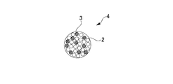
- FIG. 2 is a cross-sectional view schematically showing a first insulation coating core constituting the movable cable of the present invention.
- FIG. 3 is a plan view schematically showing a second insulation coating core constituting the movable cable of the present invention.
- FIG. 4 is a cross-sectional view schematically showing a third insulating sheath constituting the movable cable of the present invention.
- FIG. 1 shows an example of a SIM image when observing the metal structure of the first conductor (specific aluminum alloy material) constituting the movable cable according to the present invention
- FIG. It is a cross section perpendicular
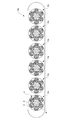
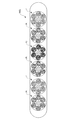
- FIG. 5 is a cross-sectional view schematically showing the movable cable of the first embodiment.
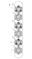
- FIG. 6 is a cross-sectional view schematically showing the movable cable of the second embodiment.
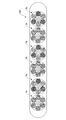
- FIG. 7 is a cross-sectional view schematically showing the movable cable of the third embodiment.
- FIG. 8 is a cross-sectional view schematically showing the movable cable of the fourth embodiment.
- FIG. 9 is a cross-sectional view schematically showing the movable cable of the fifth embodiment.
- FIG. 10 is a cross-sectional view schematically showing the movable cable of the sixth embodiment.
- FIG. 11 is a cross-sectional view schematically showing the movable cable of the seventh embodiment.
- FIG. 12 is a cross-sectional view schematically showing the movable cable of the eighth embodiment.
- FIG. 13 is a cross-sectional view schematically showing the movable cable of the ninth embodiment.
- the movable cable according to the first embodiment of the present invention is a movable cable having a conductor therein, wherein the conductor is, by mass%, Mg: 0.05 to 1.8%, Si: 0.01 to 2 .0%, Fe: 0.01 to 1.5%, one or more elements selected from the group of Cu, Ag, Zn, Ni, Co, Au, Mn, Cr, V, Zr, Ti and Sn:
- the alloy has an alloy composition containing 0.00 to 2.00% in total and the balance being Al and unavoidable impurities, and the crystal grains have a fibrous metal structure extending in one direction.
- a cross section parallel to one direction it includes a first conductor made of a specific aluminum alloy material whose average value of the dimension perpendicular to the longitudinal direction of the crystal grain is 400 nm or less, and the first conductor is the conductor of the movable cable
- the ratio of the area occupied in the whole is the cross section of the movable cable Te is in the range of 10 to 100 percent.
- the area ratio of the movable cable is "100%" it means that all the conductors constituting the movable cable are the above-described specific aluminum alloy materials.
- a "movable cable” is a cable which has a conductor inside and makes a single or several insulation coating core component.
- a “conductor” here contains both a 1st conductor and the 2nd conductor mentioned later.
- Conductor when it only describes as a “conductor” below, it shall be interpreted as the meaning which included both a 1st conductor and a 2nd conductor, without distinguishing in particular.
- Conductor is located inside the cable and refers to copper, copper alloy, aluminum and aluminum alloy material, and its cross-sectional shape is preferably circular or rectangular (plate-like), but is not particularly limited Various shapes can be adopted.
- the “insulation coated core” is formed by twisting a conductor and then insulating coating, and a plurality of strands may be twisted to form a stranded wire.
- the twisted wire can use a well-known twisting method, and any of concentric twist and collective twist may be used.
- the first conductor (specific aluminum alloy material) is, by mass%, Mg: 0.05 to 1.8%, Si: 0.01 to 2.0%, Fe: 0.01 to 1.5%, Cu, One or more elements selected from the group of Ag, Zn, Ni, Co, Au, Mn, Cr, V, Zr, Ti and Sn: containing 0.00 to 2.00% in total, the balance being Al And an inevitable impurity, and the crystal grain has a fibrous metal structure extending in one direction, and the cross section parallel to the one direction is perpendicular to the longitudinal direction of the crystal grain.
- the average value of the dimensions is 400 nm or less.
- an element component in which the lower limit value of the content range is described as “0.00%” is a component which is optionally added to the aluminum alloy material as needed. means. That is, when the elemental component is "0.00%”, it means that the elemental component is not contained in the aluminum alloy material or the content is less than the detection limit value.
- misorientation boundary is a boundary at which the contrast (channeling contrast) changes discontinuously when the metallographic structure is observed by scanning transmission electron microscopy (STEM), scanning ion microscopy (SIM) or the like. Point to In addition, the dimension perpendicular to the longitudinal direction in which the crystal grains extend corresponds to the distance between misoriented boundaries.
- the specific aluminum alloy material has a fibrous metal structure in which crystal grains extend in one direction.
- the specific aluminum alloy material has a fibrous structure in which elongated crystal grains are aligned in one direction and extend.
- Such elongated crystal grains are largely different from conventional fine crystal grains and flat crystal grains having merely a large aspect ratio. That is, the crystal grain of the present invention is an elongated shape like a fiber, and the average value of the grain size in the cross section perpendicular to the longitudinal direction is 400 nm or less.
- a fibrous metal structure in which such fine crystal grains extend in one direction is said to be a novel metal structure which did not exist in conventional aluminum alloy materials.
- the specific aluminum alloy material has a fibrous metal structure in which crystal grains extend in one direction, and in the cross section parallel to the one direction, the average grain size in the cross section perpendicular to the longitudinal direction of the crystal grains Since the value is controlled to be 400 nm or less, high strength comparable to iron-based materials and copper-based materials and excellent bending fatigue resistance can be realized.
- the metal structure of the specific aluminum alloy material is fibrous, and elongated crystal grains are aligned in one direction and extend in a fibrous form.
- “one direction” corresponds to the processing direction of the aluminum alloy material, particularly, in the case of manufacturing the first conductor (specific aluminum alloy material) by wire drawing, the wire drawing direction.
- the one direction corresponds to the longitudinal direction of the aluminum alloy material. That is, in general, the processing direction corresponds to the longitudinal direction, unless the aluminum alloy material is separated into smaller dimensions than the dimension perpendicular to the processing direction. For example, in the case of manufacturing an aluminum alloy material by wire drawing, one direction corresponds to the wire drawing direction of the aluminum alloy material.
- the average crystal grain size is preferably 400 nm or less, more preferably 330 nm or less, further preferably 250 nm Or less, particularly preferably 180 nm or less, and more preferably 150 nm or less.
- the grain size (size perpendicular to the longitudinal direction in which the crystal grains extend) of the crystal grains extending in one direction is small, so it may The accompanying crystal slip can be effectively suppressed, and higher strength and superior bending fatigue resistance than before can be realized.
- the lower limit value of the average crystal grain size is preferably as small as possible in order to realize high strength and bending fatigue resistance, but is, for example, 20 nm as a manufacturing or physical limit.
- the longitudinal dimension measured along the longitudinal direction of the crystal grains present in the specific aluminum alloy material is not particularly specified, but preferably It is 1200 nm or more, more preferably 1700 nm or more, and still more preferably 2200 nm or more.
- the longitudinal direction dimension L1 measured along the longitudinal direction and the transverse direction dimension L2 measured along the direction perpendicular to the longitudinal direction The ratio L1 / L2, ie, the aspect ratio, is preferably 10 or more, and more preferably 20 or more.
- the aspect ratio L1 / L2 is in the above range, the probability of the presence of crystal grain boundaries which may be the starting point of fatigue failure on the surface of the specific aluminum alloy material is reduced, so that the bending fatigue resistance is improved.
- the crystal grain is in the form of a fiber having a large aspect ratio, so there are few grain boundaries to be the origin of the crack.
- making the crystal grain size of the surface layer of the aluminum alloy material finer has the function of improving intergranular corrosion, and of the aluminum alloy material after plastic working It is effective in reducing surface roughness of the surface and in reducing sagging and burrs in shear processing, and is effective in enhancing the characteristics of the aluminum alloy material as a whole.
- Mg manganesium
- Mg-Si clusters and Mg-Cu clusters are formed as solute atomic clusters, the function of improving tensile strength and elongation It is an element possessed.
- the Mg content is less than 0.05%, the above-mentioned effect is insufficient, and if the Mg content exceeds 1.8%, a crystallized product is formed, and the workability (wire drawing) And bending processability etc.). Therefore, the Mg content is 0.05 to 1.8%, preferably 0.2 to 1.5%, and more preferably 0.4 to 1.0%.
- Si (silicon) has the action of solid solution in the aluminum matrix to strengthen it, and also has the action of refining crystal grains. In addition, it has an effect of improving tensile strength and fatigue life by synergy with Mg, and an element having an effect of improving tensile strength and elongation when forming Mg-Si clusters or Si-Si clusters as solute atomic clusters. It is. However, if the Si content is less than 0.01%, the above-mentioned effect is insufficient, and if the Si content exceeds 2.0%, a crystallized product is formed and the processability is reduced. Therefore, the Si content is 0.01 to 2.0%, preferably 0.2 to 1.5%, and more preferably 0.4 to 1.0%.
- Fe (iron) crystallizes or precipitates as an intermetallic compound with aluminum and essential additive elements such as Al-Fe-based, Al-Fe-Si-based and Al-Fe-Si-Mg-based during casting and homogenization heat treatment .
- An intermetallic compound mainly composed of Fe and Al as described above is referred to as an Fe-based compound in the present specification.
- the Fe-based compound contributes to the refinement of crystal grains and improves the tensile strength. Further, Fe also has an effect of improving the tensile strength by Fe dissolved in aluminum. If the content of Fe is less than 0.01%, these effects are insufficient.
- the content of Fe is 0.01 to 1.5%, preferably 0.02 to 0.80%, more preferably 0.03 to 0.50%, and still more preferably 0.04 to 0. It is 35%, more preferably 0.05 to 0.25%.
- the specific aluminum alloy material contains Mg, Si and Fe described above as essential components, but other than these elements, for example, Cu, Ag, Zn, Ni, Ti, Co, Au, Mn, Cr, V, Zr And one or more elements selected from the group of Sn can also be suitably contained as an optional component according to the required performance and the like.
- One or more elements selected from the group of Cu, Ag, Zn, Ni, Ti, Co, Au, Mn, Cr, V, Zr and Sn are all elements which particularly improve the heat resistance. From the viewpoint of sufficiently exhibiting such effects, it is preferable to set the total content of these optional additive components to 0.06% or more. However, if the total content of these optional additives is more than 2.00%, the processability is reduced. Therefore, the total content of one or more elements selected from the group of Cu, Ag, Zn, Ni, Ti, Co, Au, Mn, Cr, V, Zr and Sn is 0.00 to 2.00. %, Preferably 0.06% to 2.00%, more preferably 0.30 to 1.20%. The content of these elements may be 0.00%. In addition, these elements may be added singly or in combination of two or more elements.
- the aluminum alloy material contains at least one element selected from the group of Zn, Ni, Ti, Co, Mn, Cr, V, Zr and Sn. It is preferable to do. Furthermore, the effect of corrosion resistance is inadequate that the sum total of content of these elements is less than 0.06%. Moreover, processability will fall that the sum total of content of these elements is 2.00% or more. Therefore, from the viewpoint of corrosion resistance, the total content of one or more elements selected from the group of Zn, Ni, Ti, Co, Mn, Cr, V, Zr and Sn is preferably 0.06 to 2 More preferably, it is 0.30 to 1.20%.
- Cu is an element which particularly improves the heat resistance. It is preferable to make content of Cu into 0.06% or more from a viewpoint of fully exhibiting such an effect. However, when the content of Cu is more than 2.00%, the processability is lowered and the corrosion resistance is lowered. Therefore, the content of Cu is preferably 0.00 to 2.00%, more preferably 0.06% to 2.00%, and still more preferably 0.30 to 1.20%. The content of Cu may be 0.00%.
- Ag is an element that particularly improves heat resistance. It is preferable to make content of Ag into 0.06% or more from a viewpoint of fully exhibiting such an effect. However, when the content of Ag exceeds 2.00%, the processability is reduced. Therefore, the content of Ag is preferably 0.00 to 2.00%, more preferably 0.06% to 2.00%, and still more preferably 0.30 to 1.20%. The content of Ag may be 0.00%.
- Zn is an element which particularly improves the heat resistance.
- the content of Zn is preferably 0.06% or more.
- the content of Zn is preferably 0.00 to 2.00%, more preferably 0.06% to 2.00%, and still more preferably 0.30 to 1.20%.
- the content of Zn may be 0.00%.
- the aluminum alloy material preferably contains Zn.
- the effect of corrosion resistance is inadequate that content of Zn is less than 0.06%.
- the content of Zn is more than 2.00%, the processability is reduced. Therefore, from the viewpoint of corrosion resistance, the content of Zn is preferably 0.06 to 2.00%, more preferably 0.30 to 1.20%.
- Ni is an element which particularly improves the heat resistance. It is preferable to make content of Ni into 0.06% or more from a viewpoint of fully exhibiting such an effect. However, when the content of Ni is more than 2.00%, the processability is reduced. Therefore, the content of Ni is preferably 0.00 to 2.00%, more preferably 0.06% to 2.00%, and still more preferably 0.30 to 1.20%. The content of Ni may be 0.00%. Further, in consideration of the corrosion resistance when used in a corrosive environment, the aluminum alloy material preferably contains Ni. Furthermore, if the content of Ni is less than 0.06%, the effect of corrosion resistance is insufficient. In addition, when the content of Ni is more than 2.00%, the processability is reduced. Therefore, from the viewpoint of corrosion resistance, the content of Ni is preferably 0.06 to 2.00%, more preferably 0.30 to 1.20%.
- Co is an element which particularly improves the heat resistance. It is preferable to make content of Co into 0.06% or more from a viewpoint of fully exhibiting such an effect. However, when the content of Co exceeds 2.00%, the processability is reduced. Therefore, the content of Co is preferably 0.00 to 2.00%, more preferably 0.06% to 2.00%, and still more preferably 0.30 to 1.20%. The content of Co may be 0.00%. Further, in consideration of corrosion resistance when used in a corrosive environment, the aluminum alloy material preferably contains Co. Furthermore, when the content of Co is less than 0.06%, the effect of corrosion resistance is insufficient. In addition, when the content of Co is more than 2.00%, the processability is reduced. Therefore, from the viewpoint of corrosion resistance, the content of Co is preferably 0.06 to 2.00%, more preferably 0.30 to 1.20%.
- Au is an element that particularly improves the heat resistance. From the viewpoint of sufficiently exhibiting such effects, the content of Au is preferably set to 0.06% or more. However, when the content of Au exceeds 2.00%, the processability is reduced. Therefore, the content of Au is preferably 0.00 to 2.00%, more preferably 0.06% to 2.00%, and still more preferably 0.30 to 1.20%. The content of Au may be 0.00%.
- Mn is an element that particularly improves heat resistance. It is preferable to make content of Mn into 0.06% or more from a viewpoint of fully exhibiting such an effect. However, when the content of Mn is more than 2.00%, the processability is reduced. Therefore, the content of Mn is preferably 0.00 to 2.00%, more preferably 0.06% to 2.00%, and still more preferably 0.30 to 1.20%. The content of Mn may be 0.00%.
- the aluminum alloy material preferably contains Mn. Furthermore, when the content of Mn is less than 0.06%, the effect of corrosion resistance is insufficient. In addition, when the content of Mn is more than 2.00%, the processability is reduced. Therefore, from the viewpoint of corrosion resistance, the content of Mn is preferably 0.06 to 2.00%, more preferably 0.30 to 1.20%.
- ⁇ Cr 0.00 to 2.00%> Cr is an element which particularly improves the heat resistance. It is preferable to make content of Cr into 0.06% or more from a viewpoint of fully exhibiting such an effect. However, when the content of Cr is more than 2.00%, the processability is reduced. Therefore, the content of Cr is preferably 0.00 to 2.00%, more preferably 0.06% to 2.00%, and still more preferably 0.30 to 1.20%. The content of Cr may be 0.00%.
- the aluminum alloy material preferably contains Cr. Furthermore, if the content of Cr is less than 0.06%, the effect of corrosion resistance is insufficient. In addition, when the content of Cr is more than 2.00%, the processability is reduced. Therefore, from the viewpoint of corrosion resistance, the content of Cr is preferably 0.06 to 2.00%, more preferably 0.30 to 1.20%.
- V is an element which particularly improves the heat resistance. It is preferable to make content of V into 0.06% or more from a viewpoint of fully exhibiting such an effect. However, if the content of V is more than 2.00%, the processability is reduced. Therefore, the content of V is preferably 0.00 to 2.00%, more preferably 0.06% to 2.00%, and still more preferably 0.30 to 1.20%. The content of V may be 0.00%.
- the aluminum alloy material preferably contains V. Furthermore, when the content of V is less than 0.06%, the effect of corrosion resistance is insufficient. In addition, when the content of V is more than 2.00%, the processability is reduced. Therefore, from the viewpoint of corrosion resistance, the content of V is preferably 0.06 to 2.00%, more preferably 0.30 to 1.20%.
- Zr is an element that particularly improves the heat resistance.
- the content of Zr is preferably set to 0.06% or more.
- the content of Zr is preferably 0.00 to 2.00%, more preferably 0.06% to 2.00%, and still more preferably 0.30 to 1.20%.
- the content of Zr may be 0.00%.
- the aluminum alloy material preferably contains Zr.
- the effect of corrosion resistance is inadequate that content of Zr is less than 0.06%.
- the content of Zr is over 2.00%, the processability is lowered. Therefore, from the viewpoint of corrosion resistance, the content of Zr is preferably 0.06 to 2.00%, more preferably 0.30 to 1.20%.
- Ti is an element which refines the crystal at the time of casting and also improves the heat resistance. From the viewpoint of sufficiently exhibiting such an effect, the content of Ti is preferably 0.005% or more. However, when the content of Ti is more than 2.00%, the processability is reduced. Therefore, the content of Ti is preferably 0.00 to 2.00%, more preferably 0.06% to 2.00%, and still more preferably 0.30 to 1.20%. The content of Ti may be 0.00%. Further, in consideration of corrosion resistance when used in a corrosive environment, the aluminum alloy material preferably contains Ti. Furthermore, the effect of corrosion resistance is inadequate that content of Ti is less than 0.06%. In addition, when the content of Ti is more than 2.00%, the processability is reduced. Therefore, from the viewpoint of corrosion resistance, the content of Ti is preferably 0.06 to 2.00%, more preferably 0.30 to 1.20%.
- Sn is an element that particularly improves the heat resistance. It is preferable to make content of Sn into 0.06% or more from a viewpoint of fully exhibiting such an effect. However, if the content of Sn exceeds 2.00%, the processability is reduced. Therefore, the content of Sn is preferably 0.00 to 2.00%, more preferably 0.06% to 2.00%, and still more preferably 0.30 to 1.20%. The content of Sn may be 0.00%.
- the aluminum alloy material preferably contains Sn. Furthermore, if the content of Sn is less than 0.06%, the effect of corrosion resistance is insufficient. Moreover, processability will fall that content of Sn is more than 2.00%. Therefore, from the viewpoint of corrosion resistance, the content of Sn is preferably 0.06 to 2.00%, more preferably 0.30 to 1.20%.
- each elemental component of said Cu, Ag, Zn, Ni, Ti, Co, Au, Mn, Cr, V, Zr, and Sn improves heat resistance
- the atomic radius of the component (I) Mechanism to reduce the energy of grain boundaries due to a large difference from the atomic radius of aluminum
- (II) Mechanism to reduce the mobility of grain boundaries when entering the grain boundaries due to the large diffusion coefficient of the above components
- (III) The interaction with the vacancy is large, and a mechanism for delaying the diffusion phenomenon to trap the vacancy, etc. may be mentioned, and these mechanisms (I) to (III) act synergistically it is conceivable that.
- Unavoidable impurities mean contained impurities which can be included inevitably in the manufacturing process. Since the unavoidable impurities can also be a factor to reduce the processability depending on the content, it is preferable to suppress the content of the unavoidable impurities to some extent in consideration of the decrease in the processability.
- elements such as boron (B), bismuth (Bi), lead (Pb), gallium (Ga), strontium (Sr), are mentioned, for example.
- the upper limit value of the content of unavoidable impurities may be 0.05% or less for each of the components, and 0.15% or less in the total of the components.
- Such an aluminum alloy material can be realized by controlling the alloy composition and the manufacturing process in combination.
- the second conductor is made of a known metal material or alloy material selected from the group of copper, copper alloy, aluminum and aluminum alloy.
- the first conductor and the second conductor may have the same dimensions (especially in the case of a circular cross section, the same (strand) diameter) or different dimensions when viewed in the cross section of the movable cable. It may be done.
- the movable cable is preferably formed of a conductor having the same dimensions.
- the movable cable is formed of conductors having different dimensions, for example, when simultaneously including a stranded conductor for signal transmission.
- the cross-sectional shape of a 2nd conductor is not limited only to circular like a 1st conductor, It can be made various shapes, such as rectangular shape (plate shape).
- the conductor of the movable cable is configured using a first conductor formed by combining a plurality of types (for example, strands) having different dimensions, or, the conductor of the movable cable is configured of multiple types having different dimensions. May be configured using a second conductor formed by combining two or more (for example, strands), and further, a configuration using the conductor of the movable cable using both the first conductor and the second conductor in combination You can also
- the second conductor is preferably made of copper or a copper alloy.
- the copper-based material used as the second conductor include oxygen-free copper, tough pitch copper, phosphorus-deoxidized copper, Cu-Ag-based alloy, Cu-Sn-based alloy, Cu-Mg-based alloy, Cu-Cr-based alloy, Examples thereof include a Cu-Mg-Zn-based alloy, and a copper alloy for conductors specified by ASTM B105-05.
- the second conductor is preferably made of aluminum or an aluminum alloy.
- the aluminum-based material used as the second conductor include ECAL, Al-Zr-based, 5000-based alloy, Al-Mg-Cu-Si-based alloy, 8000-based alloy specified by ASTM B800-05, etc. Be You may use the plating wire which plated such as Sn, Ni, Ag, Cu, etc. to these aluminum-type materials.
- the second conductor comprises a cable using two or more kinds of metals, alloys, or metals and alloys with different compositions selected from the group of copper or copper alloy and aluminum or aluminum alloy. You may
- FIG. 2 is an enlarged view of the first insulating coated core 1 constituting the movable cable 10 of the first embodiment shown in FIG.
- the movable cable 10 of the present embodiment has a conductor inside.
- the conductor is configured to include the first conductor 2 made of the specific aluminum alloy material described above.
- the movable cable 10 of the embodiment shown in FIG. 5 is a flat cable, and a plurality (six in FIG. 5) of a plurality of first conductors 2 shown in FIG.
- a plurality of (six in FIG. 5) composite stranded wires 7 formed by further twisting these first insulating sheathed cores 1 using the first insulating sheathed core 1 are paralleled inside the movable cable 10 as a conductor.
- FIG. 5 shows the case where the intermediate body 6 is disposed at the center position inside the composite stranded wire 7, the intermediate body 6 can be appropriately disposed if necessary. Good.
- a steel wire such as a wire rope or a tension member using high tension fiber, May be a known method.
- the main characteristic of the configuration of the present invention is that the area ratio X of the first conductor 2 occupying in the entire conductor of the movable cable 10 is in the range of 10 to 100% in the cross section of the movable cable 10 It is in.
- the area ratio X is less than 10%, not only the weight reduction effect is small, but also sufficient durability (flexural fatigue resistance characteristics) can not be obtained, and high reliability can not be obtained.
- the area ratio X (%) of the first conductor 2 to the entire conductor of the movable cable 10 is the total sectional area of the first conductor 2 when viewed from the cross section (cross section) perpendicular to the longitudinal direction of the movable cable 10
- FIG. 6 shows the movable cable 10A of the second embodiment.
- the movable cable 10A is a flat cable, and a plurality of conductors are formed by mixing and twisting a plurality of first conductors 2 and a plurality of second conductors 3 in a mixed manner (see FIG. In (6), a plurality of (6 in FIG. 6) composite stranded wires 7A, which are formed by further twisting together the second insulating coated cores 4 including the second insulating coated cores 4 of 6), are movable as a conductor The case where it arranges in parallel inside the cable 10A and is comprised is shown.
- FIG. 7 shows the movable cable 10B of the third embodiment.
- the movable cable 10B is a flat cable, and a plurality of (six in FIG. 7) first insulating coated cores 1 formed by twisting and insulatingly coating a plurality of first conductors 2 are further twisted A plurality of wires formed by twisting together and forming a plurality of (3 in FIG. 7) first insulating sheath core 1 and a plurality of (second in FIG. 7) first insulating covering cores 1 and a plurality of (3 in FIG.
- the conductor may further include the third insulating coated core 5 in which the plurality of second conductors 3 are twisted and insulation coated.
- FIG. 8 shows a movable cable 10C of the fourth embodiment.
- the movable cable 10C is a flat type cable, and includes two composite stranded wires 7 composed of six first insulation sheathed cores 1 and three first insulation sheathed cores 1 and three third insulations.
- a configuration in which three composite stranded wires 7B formed by twisting the coated core 5 and one composite stranded wire 7C configured with six third insulating coated cores 5 are combined and arranged in parallel is shown. ing.
- FIG. 9 shows a movable cable 10D of the fifth embodiment.
- the movable cable 10D is a flat type cable, and four of four composite twisted wires 7 composed of six first insulation coated cores 1 and four third insulation coated cores 5 are used. It shows a case where the composite stranded wire 7C is combined and arranged in parallel.
- FIG. 10 shows a movable cable 10E of the sixth embodiment.
- the movable cable 10E is a flat type cable, and is configured by arranging in parallel six composite stranded wires 7B formed by twisting together three first insulating covering cores 1 and three third insulating covering cores 5 The case is shown.
- FIG. 11 shows a movable cable 10F of the seventh embodiment.
- the movable cable 10F is a flat cable, and includes three composite stranded wires 7A formed by twisting six second insulating sheathed cores 4 and three first insulating sheathed cores 1 and 3 It shows a case where three composite stranded wires 7B formed by twisting three insulation coated cores 5 are alternately arranged in parallel.
- FIG. 12 shows a movable cable 10G of the eighth embodiment.
- the movable cable 10G is a flat type cable, and the conductor is a first insulation coated core 1 in which a plurality of first conductors 2 are twisted and insulated by being twisted, a plurality of first conductors 2 and a plurality of It includes the second insulation coated core 4 in which the second conductor 3 is mixed and twisted and insulation coated, and more specifically, it is composed of a plurality of (six in FIG. 12) first insulation coated cores 1 12, and three composite stranded wires 7A formed by twisting together a plurality of (six in FIG. 12) second insulating sheath cores 4 and a plurality of six stranded wires (six in FIG. 12) The third composite sheathed core 5 is combined with one composite stranded wire 7C and arranged in parallel.
- FIG. 13 shows a movable cable 10H of the ninth embodiment.
- the movable cable 10H is a round cable, and includes two composite stranded wires 7D formed by twisting two first insulation coated cores 1 around the tension member 6A and three third insulation coatings.
- Two composite stranded wires 7E formed by twisting the cores 5 and four third insulation coated cores 5 are disposed, and these two composite stranded wires 7D, two composite stranded wires 7E and 4 are arranged.
- positioned and comprised on the outer peripheral side of the 3rd insulation covering core 5 of this book is shown.
- the first to ninth embodiments have been specifically described so far, but the present invention is not limited to these embodiments, and various configurations can be adopted.
- the first insulation coated core 1, the second insulation coated core 4 and the third insulation coated core 5 are configured such that the area ratio X of the first conductor 2 is at least one level.
- one or more cables are provided with an insulator 8 and a sheath 9 that are coated so as to include the composite stranded wire 7. It is preferable that it is comprised.
- the movable cable of the present invention can be used in various applications, and in particular, applications that require light weight, high strength and excellent bending fatigue resistance, such as elevator cables, robot cables and cabtire cables. Is particularly preferred.
- the specific aluminum alloy material constituting the movable cable according to one embodiment of the present invention is, for example, a crystal grain boundary inside of an Al-Mg-Si-Fe-based alloy material or an Al-Cu-Mg-Fe-based alloy material.
- an aluminum alloy material In a preferred method of manufacturing an aluminum alloy material according to the present embodiment, four or more cold workings [1] are performed as a final process on an aluminum alloy material having a predetermined alloy composition.
- a pretreatment step [2] of reducing the crystal grain size of the surface layer, and after cold working [1], temper annealing [3] You may Details will be described below.
- the stress state is complicated multiaxial due to the difference in orientation between adjacent crystal grains and the spatial distribution of strain between the surface near the processing tool and the inside of the bulk. It is in the state. Due to these influences, crystal grains which were in a single orientation before deformation are split into a plurality of orientations with deformation, and misoriented boundaries are formed between the split crystals.
- the formed misorientation boundary has interface energy in a structure which deviates from the normal 12-coordinate close-packed atomic arrangement. Therefore, in a normal metal structure, it is considered that the increased internal energy acts as a driving force when grain boundaries reach a certain density or higher, and dynamic or static recovery or recrystallization occurs. Therefore, the grain boundary density is considered to be saturated since grain boundaries increase and decrease simultaneously at the same time, even if the amount of deformation is increased.
- Such a phenomenon is also consistent with the relationship between the degree of processing in the conventional metallographic structure pure aluminum and pure copper and the tensile strength.
- improvement in tensile strength is observed at a relatively low degree of processing, but as the degree of processing increases, the amount of hardening tends to saturate; It does not contribute to strength increase.
- the degree of processing corresponds to the amount of deformation applied to the metal structure described above, and the saturation of the amount of hardening is considered to correspond to the saturation of grain boundary density.
- the specific aluminum alloy material of the present embodiment it is understood that while the degree of processing is increased, the grain boundary density in the surface layer is increased, that is, the accumulation of small crystal grains continues and the bending fatigue resistance continues to improve.
- the specific aluminum alloy material promotes the increase of grain boundary density by having the above-mentioned alloy composition, and can suppress the increase of internal energy even if the grain boundary becomes more than a certain density in the metal structure. It is considered to be due to As a result, it is considered that recovery and recrystallization in the metal structure can be prevented, and grain boundaries can be effectively increased in the metal structure.
- Mg having a strong interaction with lattice defects such as dislocation promotes the refinement of the crystal.
- lattice defects such as dislocation
- plastic strain is particularly introduced to the surface of the aluminum alloy material, so that while it is a very fine crystal in the vicinity of the surface layer, a relatively large crystal remains at the central position.
- the degree of processing in cold working [1] is set to 4 or more.
- Such processing degree is preferably 6 or more, more preferably 8 or more.
- the upper limit of the degree of processing is not particularly specified, but is usually 15 or less.
- the processing degree ⁇ is represented by the following formula (1), where s1 is the cross-sectional area of the specific aluminum alloy material before processing and s2 (s1> s2) is the cross-sectional area of the specific aluminum alloy material after processing. .
- the method of cold working [1] may be appropriately selected according to the shape of the target aluminum alloy (wire rod, plate, strip, foil, etc.), for example, cassette roller die, grooved roll rolling, Round wire rolling, drawing with a die or the like, swaging, etc. may be mentioned. Further, various conditions in the above processing (type of lubricating oil, processing speed, processing heat, etc.) may be appropriately adjusted within a known range.
- the pretreatment step [2] may be performed before the cold working [1].
- the pretreatment step [2] include shot peening, extrusion, swaging, skin pass, rolling, and recrystallization.
- the grain size can be graded between the surface layer and the inside of the aluminum alloy material before the cold working [1], and the crystal structure after the cold working [1] can be made finer
- the gradient of the crystal grain size can be increased.
- the various conditions (processing speed, processing heat generation, temperature, etc.) in the above steps may be suitably fired within a known range.
- aging precipitation heat treatment is not performed before cold working. If aging precipitation treatment is performed before cold working, (a) deformation concentrates in a specific place in the crystal grain, (b) intergranular cracking starts from intergranular precipitate, and so on. It is.
- the aluminum alloy material is not particularly limited as long as it has the above-mentioned alloy composition.
- an extruded material, an ingot material, a hot-rolled material, a cold-rolled material, etc. are appropriately selected according to the purpose of use. Can be used.
- tempering annealing [3] may be performed after cold working [1] for the purpose of releasing residual stress and improving elongation.
- the processing temperature of the temper annealing [3] is set to 50 to 180.degree.
- the holding time of the tempering [3] is preferably 1 to 48 hours.
- the various conditions of such heat treatment can be appropriately adjusted depending on the type and amount of unavoidable impurities, and the solid solution / precipitation state of the aluminum alloy material.
- the intermediate heat treatment in the conventional manufacturing method reduces the deformation resistance by recrystallizing the metal material, thereby reducing the load on the processing machine or reducing the wear of the tool in contact with the material such as the die or capstan.
- Such an intermediate heat treatment does not produce fine crystal grains as in the specific aluminum alloy material constituting the stranded wire conductor of the present invention.
- the aluminum alloy material of the embodiment it is effective to increase the degree of processing for the purpose of refining the crystal grains in the surface layer. Therefore, in the case of producing a wire, the smaller the diameter, and in the case of producing a plate or a foil, the thinner the thickness, the easier it is to realize the configuration of the aluminum alloy material of the present embodiment.
- the wire diameter is preferably 1.0 mm or less, more preferably 0.5 mm or less, still more preferably 0.30 mm or less, particularly preferably 0.10 mm or less.
- the lower limit of the wire diameter is not particularly provided, it is preferably 0.01 mm in consideration of workability and the like.
- the plate thickness is preferably 2.00 mm or less, more preferably 1.50 mm or less, still more preferably 1.00 mm or less, and particularly preferably 0.50 mm or less.
- the lower limit of the plate thickness is not particularly provided, it is preferably 0.02 mm in consideration of workability and the like.
- the aluminum alloy material is processed to be thin or thin as described above, it is also possible to prepare a plurality of such aluminum alloy materials and join them to make them thicker or thicker for use in the intended application.
- the method of joining can use a well-known method, for example, pressure welding, welding, joining by an adhesive agent, friction stir welding, etc. are mentioned.
- the movable composite of the present invention can be provided by insulating coating with an insulator or a sheath in a state in which various composite stranded wires (units) 7, 7A, 7B, 7C, 7D, 7E formed are disposed as conductors located inside. Cable can be manufactured.
- a known twisting method can be used as a method of twisting a plurality of conductors or a method of twisting a plurality of insulation coated cores.
- the above temper annealing [3] may be performed after the specific aluminum alloy material subjected to the cold working [1] is processed by bonding or twisting.
- the first conductor (specific aluminum alloy material) manufactured by the above manufacturing method has a predetermined alloy composition and a fibrous form in which crystal grains extend in one direction.
- the average grain size in the cross section perpendicular to the one direction is 400 nm or less. Therefore, the specific aluminum alloy material greatly exceeds the bending fatigue resistance characteristics of the conventional aluminum alloy material and exhibits strength and fatigue life comparable to that of a copper-based metal material.
- the cable is light in weight and can exhibit high strength and excellent fatigue characteristics.
- Examples 1 to 28 Using a wire or rod having the alloy composition shown in Table 1 and using a wire drawing die as the pretreatment step [2], after performing skin pass processing so that the 1-pass reduction ratio is less than 5%, a table A first conductor made of a specific aluminum alloy material having a wire diameter of 0.1 mm was produced under the production conditions shown in 1, and a cable was produced with the configuration shown in Table 1.
- the production conditions A to F shown in Table 1 are specifically as follows.
- ⁇ Manufacturing condition B> The same conditions as in the manufacturing condition A were carried out except that the degree of working of cold working [1] was 8.5.
- ⁇ Manufacturing condition D> The prepared rod was subjected to cold working [1] at a working degree of 8.5, and then to temper annealing [3] under conditions of a processing temperature of 140 ° C. and a holding time of 5 hours.
- ⁇ Manufacturing condition E> The same conditions as in the production condition A were carried out except that the working ratio of the cold drawn wire [1] was 3.5.
- ⁇ Manufacturing condition F> The prepared bar was subjected to aging precipitation heat treatment at a processing temperature of 180 ° C. and a holding time of 10 hours, and then cold working [1] was performed.
- the molten metal was transferred to a container provided with a graphite die, and a wire with a diameter of 10 mm and a length of 100 mm was continuously cast at a casting speed of about 300 mm / min through a water cooled graphite die. Then, the cumulative equivalent strain of 4.0 was introduced by the ECAP method. The recrystallization temperature at this stage was determined to be 300.degree. Then, preheating was performed at 250 ° C. for 2 hours in an inert gas atmosphere.
- a first wire drawing process with a working degree of 0.34 was performed.
- the recrystallization temperature at this stage was determined to be 300.degree.
- a primary heat treatment was performed at 260 ° C. for 2 hours in an inert gas atmosphere.
- the inside of the water-cooled wire drawing die was passed at a drawing speed of 500 mm / min, and a second wire drawing process with a processing degree of 9.3 was performed.
- the recrystallization temperature at this stage was determined to be 280.degree.
- secondary heat treatment was performed at 220 ° C. for 1 hour in an inert gas atmosphere to obtain an aluminum alloy wire rod having a wire diameter of 0.08 mm.
- the insulating material of the insulator and the sheath was made of vinyl chloride, and the weight of the insulating material was 588 g / m, and the tension members were appropriately arranged based on the examples.
- the following characteristic evaluation was performed using each produced movable cable.
- the sample for observation is a cross section parallel to the longitudinal direction (machining direction) of the above aluminum alloy wire rod and a cross section perpendicular to it, cut by FIB (Focused Ion Beam) to a thickness of 100 nm ⁇ 20 nm and finished by ion milling Was used.
- FIB Fluorine Beam
- gray contrast was used, and differences in contrast were recognized as crystal orientations, and boundaries in which contrast was discontinuously recognized were recognized as grain boundaries.
- the observation plane is photographed under a plurality of diffraction conditions by changing the angle between the electron beam and the sample by tilting it by ⁇ 3 ° according to two sample rotation axes orthogonal to each other in the sample stage of the electron microscope. Recognized.
- the observation field of view is (15 to 40) ⁇ m ⁇ (15 to 40) ⁇ m, and in the cross section parallel and perpendicular to the processing direction, the center and the line on the line corresponding to the wire diameter direction (direction perpendicular to the longitudinal direction)
- the observation was performed at a position near the middle of the surface layer (a position on the center side from the surface layer side by about 1 ⁇ 4 of the wire diameter).
- the observation field of view was appropriately adjusted according to the size of the crystal grain.
- any 100 of the crystal grains are selected, and in the cross section perpendicular to the longitudinal direction of each crystal grain, the minor axis of the crystal and the crystal in the cross section parallel to the longitudinal direction of the crystal grain
- the major axis was measured, and the aspect ratio of the crystal grain was calculated.
- an average value was calculated from the total number of observed crystal grains.
- average grain size R1 was clearly larger than 400 nm about some comparative examples, it decided not to select the crystal grain larger than 400 nm, but to exclude from a measuring object, and determined each average value Calculated.
- the aspect ratio L1 / L2 is uniformly 10 or more.
- Cable weight For cable weight, cut the cable into 1 m length and measure the weight of the cut 1 m cable (insulation material and conductor), and from the measured weight value, per 1 km of wire length Converted to the weight value of In this example, based on Conventional Example 1 (833 kg / km) in which the movable cable was manufactured using the second conductor made of pure copper material (tough pitch copper, TPC), the value of weight per 1 km of wire length is based on this standard. A level below the value of was taken as a pass level.
- Comparative Example 1 prepared using an aluminum alloy material (second conductor) whose Fe content is out of the proper range of the present invention, an aluminum alloy material whose Mg and Si contents are outside the proper range of the present invention Comparative Example 2 produced using 2 conductor) and Comparative Example 3 produced using an aluminum alloy material (second conductor) in which the total content of Cu and Cr is out of the appropriate range of the present invention are Because a break occurred during wire drawing, it was not possible to produce a movable cable.
- the movable cable of Comparative Example 5 manufactured using an aluminum alloy material (second conductor) not containing Fe has an average value of the dimension perpendicular to the longitudinal direction of the crystal grain of 470 nm, which is outside the appropriate range of the present invention , The resistance to bending fatigue was inferior.
- cold drawn wire [1] was performed after performing aging precipitation heat treatment for a treatment temperature of 180 ° C. and a holding time of 10 hours. It could not be made.
- the movable cable of Conventional Example 2 manufactured using the second conductor made of pure aluminum material (ECAL) is lighter than the movable cable of Conventional Example 1, it is necessary because the strength of the conductor is low. Since the ratio of the number of tension members is increased, the effect of weight reduction is reduced, and in addition, the bending fatigue resistance is significantly inferior.
Landscapes
- Chemical & Material Sciences (AREA)
- Engineering & Computer Science (AREA)
- Materials Engineering (AREA)
- Mechanical Engineering (AREA)
- Metallurgy (AREA)
- Organic Chemistry (AREA)
- Physics & Mathematics (AREA)
- Thermal Sciences (AREA)
- Crystallography & Structural Chemistry (AREA)
- Conductive Materials (AREA)
- Non-Insulated Conductors (AREA)
- Insulated Conductors (AREA)
Abstract
本発明は、従来の可動ケーブルと比べて、同等以上の強度を有しつつ、耐屈曲疲労特性および可撓性に優れ、さらに軽量である可動ケーブルを提供する。 本発明の可動ケーブル10は、内部に導体を有し、前記導体は、質量%で、Mg:0.05~1.8%、Si:0.01~2.0%、Fe:0.01~1.5%、Cu、Ag、Zn、Ni、Co、Au、Mn、Cr、V、Zr、TiおよびSnの群から選択される1種以上の元素:合計で0.00~2.00%を含有し、残部がAlおよび不可避不純物からなる合金組成を有し、結晶粒が、一方向に揃って延在した繊維状の金属組織を有し、前記一方向に平行な断面において、前記結晶粒の長手方向に垂直な寸法の平均値が400nm以下である特定アルミニウム合金材からなる第1導体2を含み、第1導体2は、可動ケーブル10の導体全体に占める面積割合Xが10~100%の範囲である。
Description
本発明は、例えば、エレベータケーブル、ロボットケーブル、キャブタイヤケーブル、建機用電線、産業用電線等の繰り返し変形を受ける可動ケーブルに関する。
従来から、エレベータケーブル、ロボットケーブル、キャブタイヤケーブル等の電力あるいは信号を伝送する可動ケーブルには、銅系材料が広く用いられてきた。最近では、銅系材料に比べて、比重が小さく、さらに熱膨張係数が大きい他、電気や熱の伝導性も比較的良好で、耐食性に優れるアルミニウム系材料への代替が検討されている。
しかし、純アルミニウム材は、銅系材に比べて屈曲疲労破断回数(以下、「耐屈曲疲労特性」という。)が低く、上記可動ケーブルに負荷される、数十万回から数千万回の繰り返し運動に耐えられず、断線のおそれがあるという問題があった。また、析出強化を利用し、耐屈曲疲労特性が比較的高いアルミニウム合金材である、2000系(Al-Cu系)や7000系(Al-Zn-Mg系)のアルミニウム合金材は、耐食性や耐応力腐食割れ性が劣り、また、導電性も低い等の問題があった。電気や熱の伝導性および耐食性が比較的優れている6000系のアルミニウム合金材は、アルミニウム系材料の中では耐屈曲疲労特性が高い方ではあるが、十分ではなく、更なる耐屈曲疲労特性の向上が望まれている。
導電用アルミニウム合金の耐屈曲疲労特性を向上させるための手段としては、例えば、ECAP法といった強加工法による微細結晶粒の形成方法(例えば特許文献1等)などが提案されている。しかし、ECAP法は、製造されるアルミニウム合金材の長さが短く、工業的な実用化が難しい。また、特許文献1に記載されているECAP法を用いて作製したアルミニウム合金材は、耐屈曲疲労特性が純アルミニウム材に比べて優れているものの、高くてもせいぜい10倍程度であって、長期間の使用に耐えられる程度の十分な耐屈曲疲労特性を持つとは言えない。
さらに、可動ケーブル、特にエレベータケーブルでは、ケーブル全体の自重が導体に負荷されて断線しやすいため、自重に耐えるための強度が導体に求められる。しかしながら、純銅材では、強度が低く、昇降行程が制限される。また、強度を高めるために銅合金材を使用することも提案されているが(例えば特許文献2や3等)、銅合金材の使用は、純銅材に比べて低下する導電性を、導体径を大きくするか、あるいは導体数を増加させることで補う必要があるため、導体重量の増加によるケーブル重量の増加や、可撓性の低下等の問題がある。
ケーブル重量を低減するために、導体にアルミニウム合金材を使用することも考えられる。しかしながら、従来の導体用純アルミニウム材やアルミニウム合金材は、引張強度が純銅材以下であるため、強度が低く、ケーブル自重に耐えられず、断線するおそれがある。
また、特許文献4には、Al-Fe-Mg-Si系のアルミニウム合金の芯材に、銅を被覆して冷間加工を行って強度を高めた銅被覆アルミニウム合金線が記載されている。しかしながら、特許文献4に記載の銅被覆アルミニウム合金線では、弾性限が小さいために塑性変形しやすい銅系材料が、曲げひずみの大きくなる表層に存在するため、屈曲変形が繰り返されることによって銅被覆層の表面に亀裂が発生しやすく、また、アルミニウム合金の芯材と銅被覆層に形成する化合物が亀裂の発生点となるなど、耐屈曲疲労特性に劣るという問題がある。
自重に耐えるケーブルを構成するには、従来からケーブルを構成する部材として、テンションメンバを使用することが一般的である。しかしながら、テンションメンバは、一般に、鋼製のワイヤロープが使用されるため、ケーブル重量が増加する。また、弾性率が高く、ケーブルが固くなるため、ケーブル敷設の作業性が悪くなる、といった問題もある。さらに、ケーブル自重のほとんどがテンションメンバにかかるため、テンションメンバの撚りがほどける方向へ回転モーメントがかかり、丸型ケーブルでは、ケーブルが自転してねじれの原因となり、また、平型ケーブルでは、ケーブルが変形するといった課題があった。
本発明の目的は、従来の可動ケーブルと比べて、同等以上の強度を有しつつ、耐屈曲疲労特性および可撓性に優れ、さらに軽量である可動ケーブルを提供することである。
本発明の要旨構成は、以下のとおりである。
[1]内部に導体を有する可動ケーブルであって、前記導体は、質量%で、Mg:0.05~1.8%、Si:0.01~2.0%、Fe:0.01~1.5%、Cu、Ag、Zn、Ni、Co、Au、Mn、Cr、V、Zr、TiおよびSnの群から選択される1種以上の元素:合計で0.00~2.00%を含有し、残部がAlおよび不可避不純物からなる合金組成を有し、結晶粒が、一方向に揃って延在した繊維状の金属組織を有し、前記一方向に平行な断面において、前記結晶粒の長手方向に垂直な寸法の平均値が400nm以下である特定アルミニウム合金材からなる第1導体を含み、該第1導体は、前記可動ケーブルの前記導体全体に占める面積割合が、前記可動ケーブルの横断面で見て、10~100%の範囲であることを特徴とする可動ケーブル。
[2]前記導体が、複数本の前記第1導体を撚り合わせて絶縁被覆した第1絶縁被覆心を含む、上記[1]に記載の可動ケーブル。
[3]前記導体が、複数本の前記第1導体と、銅、銅合金、アルミニウムおよびアルミニウム合金の群から選択される金属材または合金材からなる複数本の第2導体とを混在させて撚り合わせて絶縁被覆した第2絶縁被覆心を含む、上記[1]に記載の可動ケーブル。
[4]前記導体が、複数本の前記第1導体を撚り合わせて絶縁被覆した第1絶縁被覆心、および、複数本の前記第1導体と、銅、銅合金、アルミニウムおよびアルミニウム合金の群から選択される金属材または合金材からなる複数本の第2導体とを混在させて撚り合わせて絶縁被覆した第2絶縁被覆心を含む、上記[1]に記載の可動ケーブル。
[5]前記導体が、銅、銅合金、アルミニウムおよびアルミニウム合金材の群から選択される金属材または合金材からなる複数本の第2導体を撚り合わせて絶縁被覆した第3絶縁被覆心をさらに含む、上記[2]、[3]または[4]に記載の可動ケーブル。
[6]前記第1導体および前記第2導体は、前記可動ケーブルの横断面で見て、同一寸法を有する、上記[3]、[4]または[5]に記載の可動ケーブル。
[7]前記第1導体および前記第2導体は、前記可動ケーブルの横断面で見て、異なる寸法を有する、上記[3]、[4]または[5]に記載の可動ケーブル。
[8]前記第1導体の前記面積割合が1水準以上となるように、前記第1絶縁被覆心、前記第2絶縁被覆心および前記第3絶縁被覆心のうち、前記第1絶縁被覆心および前記第2絶縁被覆心の少なくとも一方の絶縁被覆心を含めて複数本撚り合わせてなる1以上の複合撚線と、該複合撚線を含むように絶縁被覆するシースとを備える1以上のケーブルで構成されている、上記[3]~[7]のいずれか1項に記載の可動ケーブル。
[9]前記特定アルミニウム合金材は、質量%で、Mg:0.2~1.8%、Si:0.2~2.0%、Fe:0.01~1.5%、ならびにCu、Ag、Zn、Ni、Co、Au、Mn、Cr、V、Zr、TiおよびSnの群から選択される1種以上の元素:合計で0.00~2.00%を含有し、残部がAlおよび不可避不純物からなる合金組成を有する、上記[1]~[8]のいずれか1項に記載の可動ケーブル。
[10]前記可動ケーブルがエレベータケーブルである、上記[1]~[9]のいずれか1項に記載の可動ケーブル。
[11]前記可動ケーブルがロボットケーブルである、上記[1]~[9]のいずれか1項に記載の可動ケーブル。
[12]前記可動ケーブルがキャブタイヤケーブルである、上記[1]~[9]のいずれか1項に記載の可動ケーブル。
本発明によれば、内部に導体を有する可動ケーブルであって、前記導体は、質量%で、Mg:0.05~1.8%、Si:0.01~2.0%、Fe:0.01~1.5%、Cu、Ag、Zn、Ni、Co、Au、Mn、Cr、V、Zr、TiおよびSnの群から選択される1種以上の元素:合計で0.00~2.00%を含有し、残部がAlおよび不可避不純物からなる合金組成を有し、結晶粒が、一方向に揃って延在した繊維状の金属組織を有し、前記一方向に平行な断面において、前記結晶粒の長手方向に垂直な寸法の平均値が400nm以下である特定アルミニウム合金材からなる第1導体を含み、該第1導体は、前記可動ケーブルの前記導体全体に占める面積割合が、前記可動ケーブルの横断面で見て、10~100%の範囲であることにより、従来の可動ケーブルと比べて、同等以上の強度を有しつつ、耐屈曲疲労特性および可撓性に優れ、さらに軽量である可動ケーブルを提供することができる。
以下、本発明を実施の形態に基づき詳細に説明する。
本発明に従う第1の実施形態の可動ケーブルは、内部に導体を有する可動ケーブルであって、前記導体は、質量%で、Mg:0.05~1.8%、Si:0.01~2.0%、Fe:0.01~1.5%、Cu、Ag、Zn、Ni、Co、Au、Mn、Cr、V、Zr、TiおよびSnの群から選択される1種以上の元素:合計で0.00~2.00%を含有し、残部がAlおよび不可避不純物からなる合金組成を有し、結晶粒が、一方向に揃って延在した繊維状の金属組織を有し、前記一方向に平行な断面において、前記結晶粒の長手方向に垂直な寸法の平均値が400nm以下である特定アルミニウム合金材からなる第1導体を含み、該第1導体は、前記可動ケーブルの前記導体全体に占める面積割合が、前記可動ケーブルの横断面で見て、10~100%の範囲である。
ここで、可動ケーブルの面積割合が「100%」とは、可動ケーブルを構成する導体がすべて、上述した特定アルミニウム合金材であることを意味する。
また、本明細書において「可動ケーブル」とは、内部に導体を有し、単数本または複数本の絶縁被覆心を構成要素とするケーブルである。また、ここでいう「導体」は、第1導体、および後述する第2導体の双方を含む。なお、以下で単に「導体」と記載している場合は、第1導体と第2導体を特に区別せず、双方を含んだ意味として解釈するものとする。「導体」は、ケーブルの内部に位置し、銅、銅合金、アルミニウムおよびアルミニウム合金材を指し、その横断面形状は、好ましくは円形状または矩形状(板状)であるが、特に限定されず、種々の形状を採用することができる。また、「絶縁被覆心」は、導体を撚線とした後に絶縁被覆したものであって、複数本を撚り合わせて撚線として形成してもよい。なお、撚線は、公知の撚り方法を用いることができ、同心撚り、集合撚りのいずれを用いてもよい。
(1)第1導体(特定アルミニウム合金材)
本発明に従う代表的な実施の形態の第1導体(特定アルミニウム合金材)の結晶粒の状態とその作用について、図1を用いて説明する。
本発明に従う代表的な実施の形態の第1導体(特定アルミニウム合金材)の結晶粒の状態とその作用について、図1を用いて説明する。
第1導体(特定アルミニウム合金材)は、質量%で、Mg:0.05~1.8%、Si:0.01~2.0%、Fe:0.01~1.5%、Cu、Ag、Zn、Ni、Co、Au、Mn、Cr、V、Zr、TiおよびSnの群から選択される1種以上の元素:合計で0.00~2.00%を含有し、残部がAlおよび不可避不純物からなる合金組成を有し、結晶粒が、一方向に揃って延在した繊維状の金属組織を有し、前記一方向に平行な断面において、前記結晶粒の長手方向に垂直な寸法の平均値が400nm以下である。
ここで、上記合金組成の元素成分のうち、含有範囲の下限値が「0.00%」と記載されている元素成分は、適宜、必要に応じて任意にアルミニウム合金材に添加される成分を意味する。すなわち、元素成分が「0.00%」の場合、その元素成分はアルミニウム合金材に含まれないか、または検出限界値未満の含有量であることを意味する。
また、本明細書において、「結晶粒」とは、方位差境界で囲まれた部分を指す。ここで「方位差境界」とは、走査透過電子顕微鏡法(STEM)や、走査イオン顕微鏡法(SIM)等によって、金属組織を観察した際に、コントラスト(チャネリングコントラスト)が不連続に変化する境界を指す。また、結晶粒が延在する長手方向に垂直な寸法は、方位差境界の間隔に相当する。
特定アルミニウム合金材は、特に、結晶粒が一方向に揃って延在した繊維状の金属組織を有する。また、特定アルミニウム合金材は、図1に示すように、細長形状の結晶粒が一方向に揃って延在状態となった繊維状組織を有している。このような細長形状の結晶粒は、従来の微細な結晶粒や、単にアスペクト比が大きい扁平な結晶粒とは大きく異なる。すなわち、本発明の結晶粒は、繊維のような細長い形状で、その長手方向に垂直な断面における結晶粒径の平均値が400nm以下である。このような微細な結晶粒が一方向に揃って延在した繊維状の金属組織は、従来のアルミニウム合金材には存在しなかった新規な金属組織といえる。
特定アルミニウム合金材は、結晶粒が一方向に揃って延在した繊維状の金属組織を有し、上記一方向に平行な断面において、上記結晶粒の長手方向に垂直断面における結晶粒径の平均値が400nm以下となるように制御されているため、鉄系材料や銅系材料に匹敵する高い強度と、優れた耐屈曲疲労特性を実現し得る。
また、特定アルミニウム合金材の金属組織は、繊維状であり、細長形状の結晶粒が一方向に揃って繊維状に延在した状態になっている。ここで、「一方向」とは、アルミニウム合金材の加工方向、特に第1導体(特定アルミニウム合金材)を伸線加工で製造する場合には、伸線方向に相当する。
また、上記一方向は、好ましくはアルミニウム合金材の長手方向に対応する。すなわち、通常アルミニウム合金材は、その加工方向に垂直な寸法よりも短い寸法に個片化されていない限り、その加工方向は、その長手方向に対応する。例えばアルミニウム合金材を伸線加工で製造する場合には、一方向はアルミニウム合金材の伸線方向に相当する。
また、結晶粒が延在する長手方向に垂直なアルミニウム合金材の断面(横断面)において、その平均結晶粒径は、好ましくは400nm以下であり、より好ましくは330nm以下であり、さらに好ましくは250nm以下であり、特に好ましくは180nm以下であり、一層好ましくは150nm以下である。このようなアルミニウム合金材の繊維状金属組織では、一方向に延在した結晶粒の粒径(結晶粒が延在する長手方向に垂直な寸法)が小さいので、負荷応力に伴うあるいは繰返し変形に伴う結晶すべりを効果的に抑制でき、従来よりも高い強度および優れた耐屈曲疲労特性を実現し得る。なお、平均結晶粒径の下限値は、高強度および耐屈曲疲労特性を実現する上で小さいほど好ましいが、製造上または物理上の限界として、例えば20nmである。
また、結晶粒が延在する長手方向に平行な特定アルミニウム合金材の断面において、特定アルミニウム合金材に存在する結晶粒における長手方向に沿って測定した長手方向寸法は、特に特定されないが、好ましくは1200nm以上であり、より好ましくは1700nm以上であり、さらに好ましくは2200nm以上である。
また、結晶粒が延在する長手方向に平行な特定アルミニウム合金材の断面において、長手方向に沿って測定した長手方向寸法L1と長手方向に垂直な方向に沿って測定した短手方向寸法L2との比L1/L2、すなわちアスペクト比は、好ましくは10以上であり、より好ましくは20以上である。アスペクト比L1/L2が上記範囲内であると、特定アルミニウム合金材の表面に疲労破壊の起点となる可能性のある結晶粒界の存在確率が低下するため、耐屈曲疲労特性が向上する。
結晶粒の状態が強度および耐屈曲疲労特性を向上させるメカニズムとして、例えば、(i)結晶粒がアスペクト比の大きな繊維状であることで、亀裂の起点となる粒界が表面に少ないため、亀裂が発生しにくくなる機構、(ii)結晶粒の短手方向寸法が小さいため、転位が移動しにくいために、負荷歪の全てあるいは大半を弾性歪として吸収できる機構、(iii)アルミニウム合金材の表面に、亀裂発生点となるステップをできにくくするとともに、亀裂が発生した際に、粒界が亀裂伸展の障害となる機構、などが挙げられ、これらの機構(i)~(iii)が相乗的に作用していると考えられる。
また、アルミニウム合金材の表層の結晶粒径を微細にすることは、耐屈曲疲労特性を改善する作用があるのに加えて、粒界腐食を改善する作用、塑性加工した後のアルミニウム合金材の表面の肌荒れを低減する作用、せん断加工した際のダレやバリを低減する作用などに有効であり、アルミニウム合金材の特性を全般的に高める効果がある。
(2)特定アルミニウム合金材の合金組成
次に、特定アルミニウム合金材の成分組成を、作用とともに以下で説明する。以下では、「質量%」を単に「%」と記載する。
次に、特定アルミニウム合金材の成分組成を、作用とともに以下で説明する。以下では、「質量%」を単に「%」と記載する。
<Mg:0.05~1.8%>
Mg(マグネシウム)は、アルミニウム母材中に固溶して強化する作用を有すると共に、結晶粒を微細にする作用を有する。また、SiやCuとの相乗効果によって引張強度や疲労寿命を向上させる作用を持ち、溶質原子クラスターとしてMg-SiクラスターやMg-Cuクラスターを形成した場合は、引張強度や伸びを向上させる作用を有する元素である。しかしながら、Mg含有量が0.05%未満だと、上記作用効果が不十分であり、また、Mg含有量が1.8%を超えると、晶出物が形成され、加工性(伸線加工性や曲げ加工性など)が低下する。したがって、Mg含有量は0.05~1.8%とし、好ましくは0.2~1.5%、さらに好ましくは0.4~1.0%である。
Mg(マグネシウム)は、アルミニウム母材中に固溶して強化する作用を有すると共に、結晶粒を微細にする作用を有する。また、SiやCuとの相乗効果によって引張強度や疲労寿命を向上させる作用を持ち、溶質原子クラスターとしてMg-SiクラスターやMg-Cuクラスターを形成した場合は、引張強度や伸びを向上させる作用を有する元素である。しかしながら、Mg含有量が0.05%未満だと、上記作用効果が不十分であり、また、Mg含有量が1.8%を超えると、晶出物が形成され、加工性(伸線加工性や曲げ加工性など)が低下する。したがって、Mg含有量は0.05~1.8%とし、好ましくは0.2~1.5%、さらに好ましくは0.4~1.0%である。
<Si:0.01~2.0%>
Si(ケイ素)は、アルミニウム母材中に固溶して強化する作用を有すると共に、結晶粒を微細にする作用を有する。また、Mgとの相乗効果によって引張強度や疲労寿命を向上させる作用を持ち、溶質原子クラスターとしてMg-Siクラスターや、Si-Siクラスターを形成した場合に引張強度や伸びを向上させる作用を有する元素である。しかしながら、Si含有量が0.01%未満だと、上記作用効果が不十分であり、また、Si含有量が2.0%を超えると、晶出物が形成され、加工性が低下する。したがって、Si含有量は0.01~2.0%とし、好ましくは0.2~1.5%、さらに好ましくは0.4~1.0%である。
Si(ケイ素)は、アルミニウム母材中に固溶して強化する作用を有すると共に、結晶粒を微細にする作用を有する。また、Mgとの相乗効果によって引張強度や疲労寿命を向上させる作用を持ち、溶質原子クラスターとしてMg-Siクラスターや、Si-Siクラスターを形成した場合に引張強度や伸びを向上させる作用を有する元素である。しかしながら、Si含有量が0.01%未満だと、上記作用効果が不十分であり、また、Si含有量が2.0%を超えると、晶出物が形成され、加工性が低下する。したがって、Si含有量は0.01~2.0%とし、好ましくは0.2~1.5%、さらに好ましくは0.4~1.0%である。
<Fe:0.01~1.5%>
Fe(鉄)は、鋳造や均質化熱処理中に、Al-Fe系、Al-Fe-Si系、Al-Fe-Si-Mg系などアルミニウムや必須添加元素と金属間化合物として晶出または析出する。これらのようにFeとAlとで主に構成される金属間化合物を本明細書ではFe系化合物と呼ぶ。Fe系化合物は、結晶粒の微細化に寄与すると共に、引張強度を向上させる。また、Feは、アルミニウム中に固溶したFeによっても引張強度を向上させる作用を有する。Feの含有量が0.01%未満であると、これらの効果が不十分である。また、Feの含有量が1.5%を超えると、Fe系化合物が多くなりすぎて、加工性が低下する。なお、鋳造時の冷却速度が遅い場合は、Fe系化合物の分散が疎となり、悪影響度が高まる。したがって、Feの含有量は、0.01~1.5%とし、好ましくは0.02~0.80%、より好ましくは0.03~0.50%、さらに好ましくは0.04~0.35%、より一層好ましくは0.05~0.25%である。
Fe(鉄)は、鋳造や均質化熱処理中に、Al-Fe系、Al-Fe-Si系、Al-Fe-Si-Mg系などアルミニウムや必須添加元素と金属間化合物として晶出または析出する。これらのようにFeとAlとで主に構成される金属間化合物を本明細書ではFe系化合物と呼ぶ。Fe系化合物は、結晶粒の微細化に寄与すると共に、引張強度を向上させる。また、Feは、アルミニウム中に固溶したFeによっても引張強度を向上させる作用を有する。Feの含有量が0.01%未満であると、これらの効果が不十分である。また、Feの含有量が1.5%を超えると、Fe系化合物が多くなりすぎて、加工性が低下する。なお、鋳造時の冷却速度が遅い場合は、Fe系化合物の分散が疎となり、悪影響度が高まる。したがって、Feの含有量は、0.01~1.5%とし、好ましくは0.02~0.80%、より好ましくは0.03~0.50%、さらに好ましくは0.04~0.35%、より一層好ましくは0.05~0.25%である。
特定アルミニウム合金材は、上述したMg、SiおよびFeを必須の含有成分とするが、これらの元素以外、例えば、Cu、Ag、Zn、Ni、Ti、Co、Au、Mn、Cr、V、ZrおよびSnの群から選択される1種以上の元素も、要求性能等に応じて適宜、任意成分として含有させることができる。
<Cu、Ag、Zn、Ni、Ti、Co、Au、Mn、Cr、V、ZrおよびSnの群から選択される1種以上の元素:合計で0.00~2.00%>
Cu、Ag、Zn、Ni、Ti、Co、Au、Mn、Cr、V、Zr、Snはいずれも、特に耐熱性を向上させる元素である。このような効果を十分に発揮させる観点から、これらの任意添加成分の含有量の合計を0.06%以上とすることが好ましい。しかし、これらの任意添加成分の含有量の合計を2.00%超とすると、加工性が低下する。したがって、Cu、Ag、Zn、Ni、Ti、Co、Au、Mn、Cr、V、ZrおよびSnの群から選択される1種以上の元素の含有量の合計は、0.00~2.00%とし、好ましくは0.06%~2.00%、より好ましくは0.30~1.20%である。なお、これらの元素の含有量は、0.00%としてもよい。また、これらの元素は、1種の元素のみの単独で添加されてもよいし、2種以上の元素の組み合わせで添加されてもよい。
Cu、Ag、Zn、Ni、Ti、Co、Au、Mn、Cr、V、Zr、Snはいずれも、特に耐熱性を向上させる元素である。このような効果を十分に発揮させる観点から、これらの任意添加成分の含有量の合計を0.06%以上とすることが好ましい。しかし、これらの任意添加成分の含有量の合計を2.00%超とすると、加工性が低下する。したがって、Cu、Ag、Zn、Ni、Ti、Co、Au、Mn、Cr、V、ZrおよびSnの群から選択される1種以上の元素の含有量の合計は、0.00~2.00%とし、好ましくは0.06%~2.00%、より好ましくは0.30~1.20%である。なお、これらの元素の含有量は、0.00%としてもよい。また、これらの元素は、1種の元素のみの単独で添加されてもよいし、2種以上の元素の組み合わせで添加されてもよい。
また、腐食環境で使用される場合の耐食性を配慮すると、アルミニウム合金材は、Zn、Ni、Ti、Co、Mn、Cr、V、ZrおよびSnの群から選択される1種以上の元素を含有することが好ましい。さらに、これらの元素の含有量の合計が0.06%未満であると、耐食性の効果が不十分である。また、これらの元素の含有量の合計が2.00%超であると、加工性が低下する。したがって、耐食性の観点からは、Zn、Ni、Ti、Co、Mn、Cr、V、ZrおよびSnの群から選択される1種以上の元素の含有量の合計は、好ましくは0.06~2.00%であり、より好ましくは0.30~1.20%である。
<Cu:0.00~2.00%>
Cuは、特に耐熱性を向上させる元素である。このような効果を十分に発揮させる観点から、Cuの含有量を0.06%以上とすることが好ましい。しかし、Cuの含有量を2.00%超とすると、加工性が低下するとともに、耐腐食性が低下する。したがって、Cuの含有量は、好ましくは0.00~2.00%、より好ましくは0.06%~2.00%、さらに好ましくは0.30~1.20%である。なお、Cuの含有量は、0.00%としてもよい。
Cuは、特に耐熱性を向上させる元素である。このような効果を十分に発揮させる観点から、Cuの含有量を0.06%以上とすることが好ましい。しかし、Cuの含有量を2.00%超とすると、加工性が低下するとともに、耐腐食性が低下する。したがって、Cuの含有量は、好ましくは0.00~2.00%、より好ましくは0.06%~2.00%、さらに好ましくは0.30~1.20%である。なお、Cuの含有量は、0.00%としてもよい。
<Ag:0.00~2.00%>
Agは、特に耐熱性を向上させる元素である。このような効果を十分に発揮させる観点から、Agの含有量を0.06%以上とすることが好ましい。しかし、Agの含有量を2.00%超とすると、加工性が低下する。したがって、Agの含有量は、好ましくは0.00~2.00%、より好ましくは0.06%~2.00%、さらに好ましくは0.30~1.20%である。なお、Agの含有量は、0.00%としてもよい。
Agは、特に耐熱性を向上させる元素である。このような効果を十分に発揮させる観点から、Agの含有量を0.06%以上とすることが好ましい。しかし、Agの含有量を2.00%超とすると、加工性が低下する。したがって、Agの含有量は、好ましくは0.00~2.00%、より好ましくは0.06%~2.00%、さらに好ましくは0.30~1.20%である。なお、Agの含有量は、0.00%としてもよい。
<Zn:0.00~2.00%>
Znは、特に耐熱性を向上させる元素である。このような効果を十分に発揮させる観点から、Znの含有量を0.06%以上とすることが好ましい。しかし、Znの含有量を2.00%超とすると、加工性が低下する。したがって、Znの含有量は、好ましくは0.00~2.00%、より好ましくは0.06%~2.00%、さらに好ましくは0.30~1.20%である。なお、Znの含有量は、0.00%としてもよい。また、腐食環境で使用される場合の耐食性を配慮すると、アルミニウム合金材は、Znを含有することが好ましい。さらに、Znの含有量が0.06%未満であると、耐食性の効果が不十分である。また、Znの含有量が2.00%超であると、加工性が低下する。したがって、耐食性の観点からは、Znの含有量は、好ましくは0.06~2.00%であり、より好ましくは0.30~1.20%である。
Znは、特に耐熱性を向上させる元素である。このような効果を十分に発揮させる観点から、Znの含有量を0.06%以上とすることが好ましい。しかし、Znの含有量を2.00%超とすると、加工性が低下する。したがって、Znの含有量は、好ましくは0.00~2.00%、より好ましくは0.06%~2.00%、さらに好ましくは0.30~1.20%である。なお、Znの含有量は、0.00%としてもよい。また、腐食環境で使用される場合の耐食性を配慮すると、アルミニウム合金材は、Znを含有することが好ましい。さらに、Znの含有量が0.06%未満であると、耐食性の効果が不十分である。また、Znの含有量が2.00%超であると、加工性が低下する。したがって、耐食性の観点からは、Znの含有量は、好ましくは0.06~2.00%であり、より好ましくは0.30~1.20%である。
<Ni:0.00~2.00%>
Niは、特に耐熱性を向上させる元素である。このような効果を十分に発揮させる観点から、Niの含有量を0.06%以上とすることが好ましい。しかし、Niの含有量を2.00%超とすると、加工性が低下する。したがって、Niの含有量は、好ましくは0.00~2.00%、より好ましくは0.06%~2.00%、さらに好ましくは0.30~1.20%である。なお、Niの含有量は、0.00%としてもよい。また、腐食環境で使用される場合の耐食性を配慮すると、アルミニウム合金材は、Niを含有することが好ましい。さらに、Niの含有量が0.06%未満であると、耐食性の効果が不十分である。また、Niの含有量が2.00%超であると、加工性が低下する。したがって、耐食性の観点からは、Niの含有量は、好ましくは0.06~2.00%であり、より好ましくは0.30~1.20%である。
Niは、特に耐熱性を向上させる元素である。このような効果を十分に発揮させる観点から、Niの含有量を0.06%以上とすることが好ましい。しかし、Niの含有量を2.00%超とすると、加工性が低下する。したがって、Niの含有量は、好ましくは0.00~2.00%、より好ましくは0.06%~2.00%、さらに好ましくは0.30~1.20%である。なお、Niの含有量は、0.00%としてもよい。また、腐食環境で使用される場合の耐食性を配慮すると、アルミニウム合金材は、Niを含有することが好ましい。さらに、Niの含有量が0.06%未満であると、耐食性の効果が不十分である。また、Niの含有量が2.00%超であると、加工性が低下する。したがって、耐食性の観点からは、Niの含有量は、好ましくは0.06~2.00%であり、より好ましくは0.30~1.20%である。
<Co:0.00~2.00%>
Coは、特に耐熱性を向上させる元素である。このような効果を十分に発揮させる観点から、Coの含有量を0.06%以上とすることが好ましい。しかし、Coの含有量を2.00%超とすると、加工性が低下する。したがって、Coの含有量は、好ましくは0.00~2.00%、より好ましくは0.06%~2.00%、さらに好ましくは0.30~1.20%である。なお、Coの含有量は、0.00%としてもよい。また、腐食環境で使用される場合の耐食性を配慮すると、アルミニウム合金材は、Coを含有することが好ましい。さらに、Coの含有量が0.06%未満であると、耐食性の効果が不十分である。また、Coの含有量が2.00%超であると、加工性が低下する。したがって、耐食性の観点からは、Coの含有量は、好ましくは0.06~2.00%であり、より好ましくは0.30~1.20%である。
Coは、特に耐熱性を向上させる元素である。このような効果を十分に発揮させる観点から、Coの含有量を0.06%以上とすることが好ましい。しかし、Coの含有量を2.00%超とすると、加工性が低下する。したがって、Coの含有量は、好ましくは0.00~2.00%、より好ましくは0.06%~2.00%、さらに好ましくは0.30~1.20%である。なお、Coの含有量は、0.00%としてもよい。また、腐食環境で使用される場合の耐食性を配慮すると、アルミニウム合金材は、Coを含有することが好ましい。さらに、Coの含有量が0.06%未満であると、耐食性の効果が不十分である。また、Coの含有量が2.00%超であると、加工性が低下する。したがって、耐食性の観点からは、Coの含有量は、好ましくは0.06~2.00%であり、より好ましくは0.30~1.20%である。
<Au:0.00~2.00%>
Auは、特に耐熱性を向上させる元素である。このような効果を十分に発揮させる観点から、Auの含有量を0.06%以上とすることが好ましい。しかし、Auの含有量を2.00%超とすると、加工性が低下する。したがって、Auの含有量は、好ましくは0.00~2.00%、より好ましくは0.06%~2.00%、さらに好ましくは0.30~1.20%である。なお、Auの含有量は、0.00%としてもよい。
Auは、特に耐熱性を向上させる元素である。このような効果を十分に発揮させる観点から、Auの含有量を0.06%以上とすることが好ましい。しかし、Auの含有量を2.00%超とすると、加工性が低下する。したがって、Auの含有量は、好ましくは0.00~2.00%、より好ましくは0.06%~2.00%、さらに好ましくは0.30~1.20%である。なお、Auの含有量は、0.00%としてもよい。
<Mn:0.00~2.00%>
Mnは、特に耐熱性を向上させる元素である。このような効果を十分に発揮させる観点から、Mnの含有量を0.06%以上とすることが好ましい。しかし、Mnの含有量を2.00%超とすると、加工性が低下する。したがって、Mnの含有量は、好ましくは0.00~2.00%、より好ましくは0.06%~2.00%、さらに好ましくは0.30~1.20%である。なお、Mnの含有量は、0.00%としてもよい。また、腐食環境で使用される場合の耐食性を配慮すると、アルミニウム合金材は、Mnを含有することが好ましい。さらに、Mnの含有量が0.06%未満であると、耐食性の効果が不十分である。また、Mnの含有量が2.00%超であると、加工性が低下する。したがって、耐食性の観点からは、Mnの含有量は、好ましくは0.06~2.00%であり、より好ましくは0.30~1.20%である。
Mnは、特に耐熱性を向上させる元素である。このような効果を十分に発揮させる観点から、Mnの含有量を0.06%以上とすることが好ましい。しかし、Mnの含有量を2.00%超とすると、加工性が低下する。したがって、Mnの含有量は、好ましくは0.00~2.00%、より好ましくは0.06%~2.00%、さらに好ましくは0.30~1.20%である。なお、Mnの含有量は、0.00%としてもよい。また、腐食環境で使用される場合の耐食性を配慮すると、アルミニウム合金材は、Mnを含有することが好ましい。さらに、Mnの含有量が0.06%未満であると、耐食性の効果が不十分である。また、Mnの含有量が2.00%超であると、加工性が低下する。したがって、耐食性の観点からは、Mnの含有量は、好ましくは0.06~2.00%であり、より好ましくは0.30~1.20%である。
<Cr:0.00~2.00%>
Crは、特に耐熱性を向上させる元素である。このような効果を十分に発揮させる観点から、Crの含有量を0.06%以上とすることが好ましい。しかし、Crの含有量を2.00%超とすると、加工性が低下する。したがって、Crの含有量は、好ましくは0.00~2.00%、より好ましくは0.06%~2.00%、さらに好ましくは0.30~1.20%である。なお、Crの含有量は、0.00%としてもよい。また、腐食環境で使用される場合の耐食性を配慮すると、アルミニウム合金材は、Crを含有することが好ましい。さらに、Crの含有量が0.06%未満であると、耐食性の効果が不十分である。また、Crの含有量が2.00%超であると、加工性が低下する。したがって、耐食性の観点からは、Crの含有量は、好ましくは0.06~2.00%であり、より好ましくは0.30~1.20%である。
Crは、特に耐熱性を向上させる元素である。このような効果を十分に発揮させる観点から、Crの含有量を0.06%以上とすることが好ましい。しかし、Crの含有量を2.00%超とすると、加工性が低下する。したがって、Crの含有量は、好ましくは0.00~2.00%、より好ましくは0.06%~2.00%、さらに好ましくは0.30~1.20%である。なお、Crの含有量は、0.00%としてもよい。また、腐食環境で使用される場合の耐食性を配慮すると、アルミニウム合金材は、Crを含有することが好ましい。さらに、Crの含有量が0.06%未満であると、耐食性の効果が不十分である。また、Crの含有量が2.00%超であると、加工性が低下する。したがって、耐食性の観点からは、Crの含有量は、好ましくは0.06~2.00%であり、より好ましくは0.30~1.20%である。
<V:0.00~2.00%>
Vは、特に耐熱性を向上させる元素である。このような効果を十分に発揮させる観点から、Vの含有量を0.06%以上とすることが好ましい。しかし、Vの含有量を2.00%超とすると、加工性が低下する。したがって、Vの含有量は、好ましくは0.00~2.00%、より好ましくは0.06%~2.00%、さらに好ましくは0.30~1.20%である。なお、Vの含有量は、0.00%としてもよい。また、腐食環境で使用される場合の耐食性を配慮すると、アルミニウム合金材は、Vを含有することが好ましい。さらに、Vの含有量が0.06%未満であると、耐食性の効果が不十分である。また、Vの含有量が2.00%超であると、加工性が低下する。したがって、耐食性の観点からは、Vの含有量は、好ましくは0.06~2.00%であり、より好ましくは0.30~1.20%である。
Vは、特に耐熱性を向上させる元素である。このような効果を十分に発揮させる観点から、Vの含有量を0.06%以上とすることが好ましい。しかし、Vの含有量を2.00%超とすると、加工性が低下する。したがって、Vの含有量は、好ましくは0.00~2.00%、より好ましくは0.06%~2.00%、さらに好ましくは0.30~1.20%である。なお、Vの含有量は、0.00%としてもよい。また、腐食環境で使用される場合の耐食性を配慮すると、アルミニウム合金材は、Vを含有することが好ましい。さらに、Vの含有量が0.06%未満であると、耐食性の効果が不十分である。また、Vの含有量が2.00%超であると、加工性が低下する。したがって、耐食性の観点からは、Vの含有量は、好ましくは0.06~2.00%であり、より好ましくは0.30~1.20%である。
<Zr:0.00~2.00%>
Zrは、特に耐熱性を向上させる元素である。このような効果を十分に発揮させる観点から、Zrの含有量を0.06%以上とすることが好ましい。しかし、Zrの含有量を2.00%超とすると、加工性が低下する。したがって、Zrの含有量は、好ましくは0.00~2.00%、より好ましくは0.06%~2.00%、さらに好ましくは0.30~1.20%である。なお、Zrの含有量は、0.00%としてもよい。また、腐食環境で使用される場合の耐食性を配慮すると、アルミニウム合金材は、Zrを含有することが好ましい。さらに、Zrの含有量が0.06%未満であると、耐食性の効果が不十分である。また、Zrの含有量が2.00%超であると、加工性が低下する。したがって、耐食性の観点からは、Zrの含有量は、好ましくは0.06~2.00%であり、より好ましくは0.30~1.20%である。
Zrは、特に耐熱性を向上させる元素である。このような効果を十分に発揮させる観点から、Zrの含有量を0.06%以上とすることが好ましい。しかし、Zrの含有量を2.00%超とすると、加工性が低下する。したがって、Zrの含有量は、好ましくは0.00~2.00%、より好ましくは0.06%~2.00%、さらに好ましくは0.30~1.20%である。なお、Zrの含有量は、0.00%としてもよい。また、腐食環境で使用される場合の耐食性を配慮すると、アルミニウム合金材は、Zrを含有することが好ましい。さらに、Zrの含有量が0.06%未満であると、耐食性の効果が不十分である。また、Zrの含有量が2.00%超であると、加工性が低下する。したがって、耐食性の観点からは、Zrの含有量は、好ましくは0.06~2.00%であり、より好ましくは0.30~1.20%である。
<Ti:0.00~2.00%>
Tiは、鋳造時の結晶を微細化させ、また、耐熱性を向上させる元素である。このような効果を十分に発揮させる観点から、Tiの含有量を0.005%以上とすることが好ましい。しかし、Tiの含有量を2.00%超とすると、加工性が低下する。したがってTiの含有量は、好ましくは0.00~2.00%、より好ましくは0.06%~2.00%、さらに好ましくは0.30~1.20%である。なお、Tiの含有量は、0.00%としてもよい。また、腐食環境で使用される場合の耐食性を配慮すると、アルミニウム合金材は、Tiを含有することが好ましい。さらに、Tiの含有量が0.06%未満であると、耐食性の効果が不十分である。また、Tiの含有量が2.00%超であると、加工性が低下する。したがって、耐食性の観点からは、Tiの含有量は、好ましくは0.06~2.00%であり、より好ましくは0.30~1.20%である。
Tiは、鋳造時の結晶を微細化させ、また、耐熱性を向上させる元素である。このような効果を十分に発揮させる観点から、Tiの含有量を0.005%以上とすることが好ましい。しかし、Tiの含有量を2.00%超とすると、加工性が低下する。したがってTiの含有量は、好ましくは0.00~2.00%、より好ましくは0.06%~2.00%、さらに好ましくは0.30~1.20%である。なお、Tiの含有量は、0.00%としてもよい。また、腐食環境で使用される場合の耐食性を配慮すると、アルミニウム合金材は、Tiを含有することが好ましい。さらに、Tiの含有量が0.06%未満であると、耐食性の効果が不十分である。また、Tiの含有量が2.00%超であると、加工性が低下する。したがって、耐食性の観点からは、Tiの含有量は、好ましくは0.06~2.00%であり、より好ましくは0.30~1.20%である。
<Sn:0.00~2.00%>
Snは、特に耐熱性を向上させる元素である。このような効果を十分に発揮させる観点から、Snの含有量を0.06%以上とすることが好ましい。しかし、Snの含有量を2.00%超とすると、加工性が低下する。したがって、Snの含有量は、好ましくは0.00~2.00%、より好ましくは0.06%~2.00%、さらに好ましくは0.30~1.20%である。なお、Snの含有量は、0.00%としてもよい。また、腐食環境で使用される場合の耐食性を配慮すると、アルミニウム合金材は、Snを含有することが好ましい。さらに、Snの含有量が0.06%未満であると、耐食性の効果が不十分である。また、Snの含有量が2.00%超であると、加工性が低下する。したがって、耐食性の観点からは、Snの含有量は、好ましくは0.06~2.00%であり、より好ましくは0.30~1.20%である。
Snは、特に耐熱性を向上させる元素である。このような効果を十分に発揮させる観点から、Snの含有量を0.06%以上とすることが好ましい。しかし、Snの含有量を2.00%超とすると、加工性が低下する。したがって、Snの含有量は、好ましくは0.00~2.00%、より好ましくは0.06%~2.00%、さらに好ましくは0.30~1.20%である。なお、Snの含有量は、0.00%としてもよい。また、腐食環境で使用される場合の耐食性を配慮すると、アルミニウム合金材は、Snを含有することが好ましい。さらに、Snの含有量が0.06%未満であると、耐食性の効果が不十分である。また、Snの含有量が2.00%超であると、加工性が低下する。したがって、耐食性の観点からは、Snの含有量は、好ましくは0.06~2.00%であり、より好ましくは0.30~1.20%である。
上記Cu、Ag、Zn、Ni、Ti、Co、Au、Mn、Cr、V、ZrおよびSnの各元素成分が、耐熱性を向上させるメカニズムとしては、例えば(I)上記成分の原子半径と、アルミニウムの原子半径との差が大きいために結晶粒界のエネルギーを低下させる機構、(II)上記成分の拡散係数が大きいために粒界に入り込んだ場合に粒界の移動度を低下させる機構、(III)空孔との相互作用が大きく、空孔をトラップするために拡散現象を遅延させる機構、などが挙げられ、これらの機構(I)~(III)が相乗的に作用しているものと考えられる。
<残部:Alおよび不可避不純物>
上述した成分以外の残部は、Alおよび不可避不純物である。不可避不純物は、製造工程上、不可避的に含まれうる含有レベルの不純物を意味する。不可避不純物は、含有量によっては加工性を低下させる要因にもなりうるため、加工性の低下を加味して不可避不純物の含有量をある程度抑制することが好ましい。不可避不純物として挙げられる成分としては、例えば、ホウ素(B)、ビスマス(Bi)、鉛(Pb)、ガリウム(Ga)、ストロンチウム(Sr)等の元素が挙げられる。なお、不可避不純物の含有量の上限値は、上記成分毎に0.05%以下、上記成分の合計で0.15%以下とすればよい。
上述した成分以外の残部は、Alおよび不可避不純物である。不可避不純物は、製造工程上、不可避的に含まれうる含有レベルの不純物を意味する。不可避不純物は、含有量によっては加工性を低下させる要因にもなりうるため、加工性の低下を加味して不可避不純物の含有量をある程度抑制することが好ましい。不可避不純物として挙げられる成分としては、例えば、ホウ素(B)、ビスマス(Bi)、鉛(Pb)、ガリウム(Ga)、ストロンチウム(Sr)等の元素が挙げられる。なお、不可避不純物の含有量の上限値は、上記成分毎に0.05%以下、上記成分の合計で0.15%以下とすればよい。
このようなアルミニウム合金材は、合金組成や製造プロセスを組み合わせて制御することにより実現できる。
(3)第2導体
第2導体は、銅、銅合金、アルミニウムおよびアルミニウム合金の群から選択される、公知の金属材または合金材で構成されている。
第2導体は、銅、銅合金、アルミニウムおよびアルミニウム合金の群から選択される、公知の金属材または合金材で構成されている。
さらに、第1導体と第2導体は、可動ケーブルの横断面で見て、同一寸法(特に円形断面の場合には、同一(素線)径)を有していても、あるいは異なる寸法を有していてもよい。例えば、耐屈曲疲労特性を重視する場合には、可動ケーブルは、同一寸法を有する導体で形成されていることが好ましい。また、撚線導体(例えば絶縁被覆心、複合撚線等)を構成する導体と導体の間及び、導体と被覆の間に形成される隙間の低減を重視する場合や、同一ケーブル内に電力伝送と信号伝送を行う撚線導体を同時に含む場合等には、可動ケーブルは、異なる寸法を有する導体で形成されていることが好ましい。また、第2導体の断面形状は、第1導体と同様、円形だけには限定されず、矩形状(板状)など種々の形状にすることができる。加えて、可動ケーブルの導体を、異なる寸法をもつ複数種類のもの(例えば素線)を組み合わせて形成した第1導体を用いて構成し、あるいは、可動ケーブルの導体を、異なる寸法をもつ複数種類のもの(例えば素線)を組み合わせて形成した第2導体を用いて構成してもよく、さらには、可動ケーブルの導体を、これらの第1導体および第2導体の双方を組み合わせて用いて構成することもできる。
なお、導体の抵抗の低減を重視する場合には、第2導体は、銅または銅合金で構成されていることが好ましい。第2導体として用いる銅系材料の具体例としては、無酸素銅、タフピッチ銅、リン脱酸銅、Cu-Ag系合金、Cu-Sn系合金、Cu-Mg系合金、Cu-Cr系合金、Cu-Mg-Zn系合金、その他、ASTM B105-05で規定されている導体用銅合金等が挙げられる。また、これらの銅系材料に、Sn、Ni、Ag、Cuなどのめっきを施しためっき線を用いても良い。
また、ケーブルの軽量化を重視する場合には、第2導体は、アルミニウムまたはアルミニウム合金で構成されていることが好ましい。第2導体として用いるアルミニウム系材料の具体例としては、ECAL、Al-Zr系、5000系合金、Al-Mg-Cu-Si系合金、ASTM B800-05で規定されている8000系合金などが挙げられる。これらのアルミニウム系材料に、Sn、Ni、Ag、Cuなどのめっきを施した、めっき線を用いても良い。
さらに、第2導体は、銅または銅合金と、アルミニウムまたはアルミニウム合金との群から選択される組成の異なる2種類以上の、金属材、合金材、または金属材と合金材を用いてケーブルを構成してもよい。
(4)可動ケーブル
次に、本実施形態の可動ケーブルの導体の構成とその作用について、エレベータケーブルを例として、図2~図13を用いて説明する。
次に、本実施形態の可動ケーブルの導体の構成とその作用について、エレベータケーブルを例として、図2~図13を用いて説明する。
図2は、図5に示す第1の実施形態の可動ケーブル10を構成する第1絶縁被覆心1を拡大して示したものである。本実施形態の可動ケーブル10は、内部に導体を有する。該導体は、上述した特定アルミニウム合金材からなる第1導体2を含んで構成されている。図5に示す実施形態の可動ケーブル10は、平型ケーブルであり、図2に示す複数本の第1導体2を撚り合わせて絶縁被覆して形成した、複数本(図5では6本)の第1絶縁被覆心1を用い、これらの第1絶縁被覆心1をさらに撚り合わせて形成した、複数本(図5では6本)の複合撚線7を、導体として可動ケーブル10の内部に並列配置した場合を示している。また、図5では、複合撚線7の内部の中央位置に、介在体6を配置した場合を示しているが、かかる介在体6は、必要に応じて適宜配置することができ、なくてもよい。また、ケーブル長が長尺となり、導体のみではケーブル自重を支えることができない場合には、例えばワイヤロープ等の鋼製線材や、高張力繊維を用いたテンションメンバを配置することが好ましく、その配置は、公知の方法を用いてよい。
そして、本発明の構成上の主な特徴は、可動ケーブル10の導体全体に占める第1導体2の面積割合Xを、可動ケーブル10の横断面で見て、10~100%の範囲とすることにある。かかる構成を採用することによって、従来の可動ケーブルと比べて、同等以上の強度を有しつつ、耐屈曲疲労特性および可撓性に優れ、さらに軽量である可動ケーブルを提供することができる。前記面積割合Xが10%を下回ると、軽量化効果が小さいだけでなく、十分な耐久性(耐屈曲疲労特性)が得られず、高い信頼性を得られない。
ここで、可動ケーブル10の導体全体に占める第1導体2の面積割合X(%)は、可動ケーブル10の長手方向に垂直な断面(横断面)から見て、第1導体2の合計断面積S1と、可動ケーブル10を構成する導体の合計断面積Sとで、以下の式で表される。
X(%)=(S1/S)×100
X(%)=(S1/S)×100
また、図6は、第2の実施形態の可動ケーブル10Aを示したものである。この可動ケーブル10Aは、平型ケーブルであり、導体が、複数本の第1導体2と、複数本の第2導体3とを混在させて撚り合わせて絶縁被覆して形成した、複数本(図6では6本)の第2絶縁被覆心4を含み、これらの第2絶縁被覆心4をさらに撚り合わせて形成した、複数本(図6では6本)の複合撚線7Aを、導体として可動ケーブル10Aの内部に並列配置して構成した場合を示している。
さらに、図7は、第3の実施形態の可動ケーブル10Bを示したものである。この可動ケーブル10Bは、平型ケーブルであり、複数本の第1導体2を撚り合わせて絶縁被覆して形成した複数本(図7では6本)の第1絶縁被覆心1をさらに撚り合わせて形成した3本の複合撚線7と、複数本(図7では3本)の第1絶縁被覆心1および複数本の第2導体3を撚り合わせて絶縁被覆して形成した複数本(図7では3本)の第3絶縁被覆心5を撚り合わせて形成した3本の複合撚線7Bとを、導体として可動ケーブル10Bの内部に交互に並列配置して構成した場合を示している。このように、本発明では、導体が、複数本の第2導体3を撚り合わせて絶縁被覆した第3絶縁被覆心5をさらに含んでいてもよい。
図8は、第4の実施形態の可動ケーブル10Cを示したものである。この可動ケーブル10Cは、平型ケーブルであり、6本の第1絶縁被覆心1で構成される2本の複合撚線7と、3本の第1絶縁被覆心1および3本の第3絶縁被覆心5を撚り合わせて形成した3本の複合撚線7Bと、6本の第3絶縁被覆心5で構成される1本の複合撚線7Cを組み合わせて並列配置して構成した構成を示している。
図9は、第5の実施形態の可動ケーブル10Dを示したものである。この可動ケーブル10Dは、平型ケーブルであり、6本の第1絶縁被覆心1で構成される2本の複合撚線7と、6本の第3絶縁被覆心5で構成される4本の複合撚線7Cとを組み合わせて並列配置して構成した場合を示している。
図10は、第6の実施形態の可動ケーブル10Eを示したものである。この可動ケーブル10Eは、平型ケーブルであり、3本の第1絶縁被覆心1および3本の第3絶縁被覆心5を撚り合わせて形成した6本の複合撚線7Bを並列配置して構成した場合を示している。
図11は、第7の実施形態の可動ケーブル10Fを示したものである。この可動ケーブル10Fは、平型ケーブルであり、6本の第2絶縁被覆心4を撚り合わせて形成した3本の複合撚線7Aと、3本の第1絶縁被覆心1および3本の第3絶縁被覆心5を撚り合わせて形成した3本の複合撚線7Bとを交互に並列配置して構成した場合を示している。
図12は、第8の実施形態の可動ケーブル10Gを示したものである。この可動ケーブル10Gは、平型ケーブルであり、導体が、複数本の第1導体2を撚り合わせて絶縁被覆した第1絶縁被覆心1、および、複数本の第1導体2と、複数本の第2導体3とを混在させて撚り合わせて絶縁被覆した第2絶縁被覆心4を含んでおり、より具体的には、複数本(図12では6本)の第1絶縁被覆心1で構成される2本の複合撚線7と、複数本(図12では6本)の第2絶縁被覆心4を撚り合わせて形成した3本の複合撚線7Aと、複数本(図12では6本)の第3絶縁被覆心5で構成される1本の複合撚線7Cとを組み合わせて並列配置して構成した場合を示している。
図13は、第9の実施形態の可動ケーブル10Hを示したものである。この可動ケーブル10Hは、丸型ケーブルであり、テンションメンバ6Aの周りに、2本の第1絶縁被覆心1を撚り合わせて形成した2本の複合撚線7Dと、3本の第3絶縁被覆心5を撚り合わせて形成した2本の複合撚線7Eと、4本の第3絶縁被覆心5とを配置し、これらの2本の複合撚線7D、2本の複合撚線7Eおよび4本の第3絶縁被覆心5の外周側に、さらに24本の第1絶縁被覆心1を配置して構成した場合を示している。
ここまで第1~第9の実施形態を具体的に説明してきたが、本発明では、これらの実施形態だけには限定されず、種々の構成を採用することができる。
ここまで第1~第9の実施形態を具体的に説明してきたが、本発明では、これらの実施形態だけには限定されず、種々の構成を採用することができる。
また、本発明の可動ケーブル10は、第1導体2の前記面積割合Xが、1水準以上となるように、第1絶縁被覆心1、第2絶縁被覆心4および第3絶縁被覆心5のうち、第1絶縁被覆心1および第2絶縁被覆心4の少なくとも一方の絶縁被覆心を含めて複数本撚り合わせてなる1以上の複合撚線7、7A、7B、7Dと、図5~図13に示すように、複合撚線7を含むように絶縁被覆する絶縁体8やシース9とを備える1以上のケーブル(図5~図13ではいずれも単一のケーブルの場合を示す。)で構成されていることが好ましい。
<可動ケーブルの用途>
本発明の可動ケーブルは、種々の用途に使用することができ、特に、軽量で高強度かつ優れた耐屈曲疲労特性を必要とする用途、例えば、エレベータケーブル、ロボットケーブル、キャブタイヤケーブルに適用することが特に好適である。
本発明の可動ケーブルは、種々の用途に使用することができ、特に、軽量で高強度かつ優れた耐屈曲疲労特性を必要とする用途、例えば、エレベータケーブル、ロボットケーブル、キャブタイヤケーブルに適用することが特に好適である。
[可動ケーブルの製造方法]
次に、本発明に従う可動ケーブルを構成する第1導体(特定アルミニウム合金材)の製造方法の一例を以下で説明する。このような本発明の一実施形態による可動ケーブルを構成する特定アルミニウム合金材は、例えばAl-Mg-Si-Fe系合金材やAl-Cu-Mg-Fe系合金材の、内部に結晶粒界を高密度で導入することにより、高強度化および高疲労寿命化を図ることを特徴とする。特に、曲げ歪の大きくなる表層近傍に小さな結晶粒を集積させることにより、さらなる高疲労寿命化を図ることができる。したがって、従来のアルミニウム合金材で一般的に行われてきた、Mg-Si化合物の析出硬化させる方法や、固溶元素により固溶強化させる方法とは、高強度化および高疲労寿命化に対するアプローチが大きく異なる。
次に、本発明に従う可動ケーブルを構成する第1導体(特定アルミニウム合金材)の製造方法の一例を以下で説明する。このような本発明の一実施形態による可動ケーブルを構成する特定アルミニウム合金材は、例えばAl-Mg-Si-Fe系合金材やAl-Cu-Mg-Fe系合金材の、内部に結晶粒界を高密度で導入することにより、高強度化および高疲労寿命化を図ることを特徴とする。特に、曲げ歪の大きくなる表層近傍に小さな結晶粒を集積させることにより、さらなる高疲労寿命化を図ることができる。したがって、従来のアルミニウム合金材で一般的に行われてきた、Mg-Si化合物の析出硬化させる方法や、固溶元素により固溶強化させる方法とは、高強度化および高疲労寿命化に対するアプローチが大きく異なる。
本実施形態のアルミニウム合金材の好ましい製造方法では、所定の合金組成を有するアルミニウム合金素材に対し、最終加工として加工度で4以上の冷間加工[1]を行う。また、必要に応じて、冷間加工[1]の前に、表層の結晶粒径を微細にする前処理工程[2]、および、冷間加工[1]の後に、調質焼鈍[3]を行ってもよい。以下、詳しく説明する。
通常、金属材料に繰返し応力が加わると、金属結晶の変形の素過程として、弾性変形とともに結晶すべりが生じる。このような結晶すべりが生じ易い金属材ほど、強度が低く、また、材料表面に亀裂発生点を作るため、疲労破壊しやすいといえる。そのため、金属材の高強度化および高疲労寿命化に当たっては、金属組織内で生じる結晶すべりを抑制することが重要となる。このような結晶すべりの阻害要因としては、金属組織内の結晶粒界の存在が挙げられる。このような結晶粒界は、金属材に応力が加わった際に、結晶すべりが金属組織内で伝播することを抑制でき、その結果、金属材の強度および疲労寿命は高められる。
そのため、金属材の高強度化および高疲労寿命化にあたっては、金属組織内に結晶粒界を高密度で導入する、すなわち小さな結晶粒を集積させることが望ましいと考えられる。ここで、結晶粒界の形成機構としては、例えば、次のような金属組織の変形に伴う、金属結晶の分裂が考えられる。
通常、多結晶材料の内部では、隣接する結晶粒同士の方位の違いや、加工工具と接する表層近傍とバルク内部との間の歪みの空間分布に起因して、応力状態は、複雑な多軸状態となっている。これらの影響により、変形前に単一方位であった結晶粒が、変形に伴って複数の方位に分裂していき、分裂した結晶同士の間には方位差境界が形成される。
しかし、形成された方位差境界は、通常の12配位の最密原子配列から乖離している構造で界面エネルギーを有する。そのため、通常の金属組織では、結晶粒界が一定密度以上になると、増加した内部エネルギーが駆動力となり、動的もしくは静的な回復や再結晶が起きると考えられる。そのため、通常は、変形量を増やしても、結晶粒界の増加と減少が同時に起きるため、粒界密度は飽和状態になると考えられる。
このような現象は、従来の金属組織である純アルミニウムや純銅における加工度と引張強度の関係とも一致する。通常の金属組織である純アルミニウムや純銅は、比較的低い加工度では引張強度の向上(硬化)がみられるが、加工度が増すほど硬化量は飽和する傾向にあり、一定以上の加工度は強度上昇に寄与しない。ここで、加工度は、上述の金属組織に加わる変形量に対応し、硬化量の飽和は粒界密度の飽和に対応すると考えられる。
また、単に加工を行うだけでは、強度および疲労寿命は上昇する一方で、延性が低下していき、加工時や使用時に、断線しやすくなるといった問題がある。これは、結晶内に転位が多量に導入されるため転位密度が飽和し、それ以上の塑性変形を許容できなくなるためと考えられる。
これに対し、本実施形態の特定アルミニウム合金材では、加工度が増すとともに表層での結晶粒界密度の増加、すなわち小さな結晶粒の集積が継続し、耐屈曲疲労特性が向上し続けることがわかった。これは、特定アルミニウム合金材が、上記合金組成を有することにより、結晶粒界密度の増加を促進し、金属組織内で結晶粒界が一定密度以上になっても、内部エネルギーの増加を抑制できることによるものと考えられる。その結果、金属組織内での回復や再結晶を防止でき、効果的に金属組織内に結晶粒界を増加できると考えられる。
このようなMgとSi、あるいは、MgとCuの複合添加による結晶微細化のメカニズムは必ずしも明らかではないが、(i)転位といった格子欠陥と強い相互作用を持つMgが、結晶の微細化を促進することで、結晶分断を促進すること、(ii)Al原子に対して原子半径の大きいMg原子と小さいSi原子あるいはCuとが粒界での原子配列のミスマッチを緩和することで、加工に伴う内部エネルギーの増加を効果的に抑制できることによるものと考えられる。
また、本実施形態のアルミニウム合金材では、特に、その表面に塑性ひずみが導入されるため、表層近傍では非常に微細な結晶である一方で、中心位置では比較的大きな結晶が残ったままである。このような結晶組織を持つことで、ねじりや曲げ変形時には、表層の微細な結晶が有効に働き、伸びに対しては、中心位置の大きな結晶が有効に働き、製造時に断線し難い。
本実施形態のアルミニウム合金材の製造方法では、冷間加工[1]における加工度を4以上とする。特に、大きな加工度による加工を行うことにより、金属組織の変形に伴う金属結晶の分裂を促すことができ、アルミニウム合金材の内部に結晶粒界を高密度で導入できる。その結果、アルミニウム合金材の表層では小さな結晶粒が集積し、耐屈曲疲労特性が大幅に向上する。このような加工度は、好ましくは6以上、より好ましくは8以上とする。また加工度の上限は特に規定されないが、通常は15以下である。
なお、加工度ηは、加工前の特定アルミニウム合金材の断面積をs1、加工後の特定アルミニウム合金材の断面積をs2(s1>s2)とするとき、下記式(1)で表される。
加工度(無次元):η=ln(s1/s2) ・・・(1)
加工度(無次元):η=ln(s1/s2) ・・・(1)
また、冷間加工[1]の方法は、目的とするアルミニウム合金材の形状(線棒材、板材、条、箔など)に応じて適宜選択すればよく、例えばカセットローラーダイス、溝ロール圧延、丸線圧延、ダイス等による引抜き加工、スエージング等が挙げられる。また、上記のような加工における諸条件(潤滑油の種類、加工速度、加工発熱等)は、公知の範囲で適宜調整すればよい。
また、冷間加工[1]の前に前処理工程[2]を行ってもよい。前処理工程[2]については、ショットピーニング、押出し、スエージング、スキンパス、圧延、再結晶法等が挙げられる。これにより、冷間加工[1]の前段階で、アルミニウム合金材の表層と内部との間で結晶粒径に勾配を付けることができ、冷間加工[1]後の結晶組織を、より微細に、かつ、結晶粒径の勾配を大きくすることができる。上記工程における諸条件(加工速度、加工発熱、温度等)は、公知の範囲で適宜焼成すればよい。なお、本発明では、冷間加工前に時効析出熱処理は行なわない。冷間加工前に時効析出処理を行うと、(a)結晶粒内の特定の場所に変形が集中する、(b)粒界析出物を起点として粒界割れする、などにより断線が発生するからである。
また、アルミニウム合金素材は、上記合金組成を有するものであれば特に限定はなく、例えば、押出材、鋳塊材、熱間圧延材、冷間圧延材等を、使用目的に応じて適宜選択して用いることができる。
また、残留応力の解放や伸びの向上を目的として、冷間加工[1]の後に調質焼鈍[3]を行ってもよい。調質焼鈍[3]の処理温度は50~180℃とする。調質焼鈍[3]の処理温度が50℃未満の場合には、上記のような効果が得られにくく、180℃を超える場合には、回復や再結晶によって結晶粒の成長が起き、強度および疲労寿命が低下する。また、調質焼鈍[3]の保持時間は好ましくは1~48時間である。なお、このような熱処理の諸条件は、不可避不純物の種類や量、およびアルミニウム合金素材の固溶・析出状態によって、適宜調節することができる。
なお、従来の製法における中間熱処理は、金属材料を再結晶させることによって変形抵抗を下げて、加工機械の負荷を低減したり、ダイスやキャプスタンなどの材料と接する工具の摩耗を低減させたりすることが目的であったが、そのような中間熱処理では、本発明の撚線導体を構成する特定アルミニウム合金材のように、微細な結晶粒は得られない。
また、上述のように、実施の形態のアルミニウム合金材は、その表層の結晶粒の微細化のために加工度を大きくすることが有効である。そのため、線材を作製する場合には、細径にするほど、また、板材や箔を作製する場合には、薄厚にするほど、本実施形態のアルミニウム合金材の構成を実現し易い。
特に、アルミニウム合金材が線材である場合、その線径は、好ましくは1.0mm以下、より好ましくは0.5mm以下、さらに好ましくは0.30mm以下、特に好ましくは0.10mm以下である。なお、線径の下限は、特に設けないが、作業性等を考慮し、0.01mmであることが好ましい。
また、アルミニウム合金材が板材である場合、その板厚は、好ましくは2.00mm以下、より好ましくは1.50mm以下、さらに好ましくは1.00mm以下、特に好ましくは0.50mm以下である。なお、板厚の下限は、特に設けないが、作業性等を考慮し、0.02mmであることが好ましい。
さらに、上述のようにアルミニウム合金材は、細くまたは薄く加工されるが、このようなアルミニウム合金材を複数用意し、これらを接合して太くまたは厚くして、目的の用途に使用することもできる。なお、接合の方法は、公知の方法を用いることができ、例えば圧接、溶接、接着剤による接合、摩擦攪拌接合等が挙げられる。
次に、上記の手順で作製した第1導体(特定アルミニウム合金材)や、第2導体を用い、上述したように撚り合わせて第1絶縁被覆心1、第2絶縁被覆心4を作製し、さらに、必要に応じて、第3絶縁被覆心5を作製し、これらの第1絶縁被覆心1および第2絶縁被覆心4(必要に応じて第3絶縁被覆心5)の少なくとも1方を用いて形成した種々の複合撚線(ユニット)7、7A、7B、7C、7D、7Eを、内部に位置する導体として配置した状態で、絶縁体やシースで絶縁被覆することによって、本発明の可動ケーブルを製造することができる。複数本の導体を撚り合わせる方法や、複数本の絶縁被覆心を撚り合わせる方法については、公知の撚り合せ方法を用いることができる。なお、上記調質焼鈍[3]は、上記冷間加工[1]を行った特定アルミニウム合金材を、接合あるいは撚り合わせによる加工を行った後に、行ってもよい。
以上説明した実施の形態によれば、上記の製造方法によって製造される第1導体(特定アルミニウム合金材)は、所定の合金組成を有すると共に、結晶粒が一方向に揃って延在した繊維状の金属組織を有し、上記一方向に垂直な断面における結晶粒径の平均値が400nm以下である。そのため、特定アルミニウム合金材は、従来のアルミニウム合金材の耐屈曲疲労特性を大きく超え、銅系の金属材料に匹敵する強度および疲労寿命を示すので、この第1導体を用いて導体を構成した可動ケーブルは、軽量で高強度かつ優れた疲労特性を発揮することができる。
以上、実施の形態について説明したが、本発明は上記実施の形態に限定されるものではなく、本発明の概念および特許請求の範囲に含まれるあらゆる態様を含み、本発明の範囲内で種々に改変することができる。
次に、実施例および比較例について説明するが、本発明はこれら実施例に限定されるものではない。
(実施例1~28)
表1に示す合金組成を有する線材、または、棒材を用い、前処理工程[2]として線引きダイスを用い、1パス減面率が5%未満となるようにスキンパス加工を行った後、表1に示す製造条件にて、線径0.1mmの特定アルミニウム合金材からなる第1導体を作製し、表1に示す構成でケーブルを作製した。
表1に示す合金組成を有する線材、または、棒材を用い、前処理工程[2]として線引きダイスを用い、1パス減面率が5%未満となるようにスキンパス加工を行った後、表1に示す製造条件にて、線径0.1mmの特定アルミニウム合金材からなる第1導体を作製し、表1に示す構成でケーブルを作製した。
(比較例1~7)
表1に示す合金組成を有する線材、または、棒材を用い、表1に示す製造条件にて、アルミニウム合金材からなる(第1)導体を作製し、表1に示す構成でケーブルを作製した。
表1に示す合金組成を有する線材、または、棒材を用い、表1に示す製造条件にて、アルミニウム合金材からなる(第1)導体を作製し、表1に示す構成でケーブルを作製した。
なお、表1に示す製造条件A~Fは、具体的には以下のとおりである。
<製造条件A>
準備した棒材に対し、加工度6.0の冷間加工[1]を行った。なお、調質焼鈍[3]は行わなかった。
準備した棒材に対し、加工度6.0の冷間加工[1]を行った。なお、調質焼鈍[3]は行わなかった。
<製造条件B>
冷間加工[1]の加工度を8.5とした以外は、製造条件Aと同じ条件で行った。
冷間加工[1]の加工度を8.5とした以外は、製造条件Aと同じ条件で行った。
<製造条件C>
冷間加工[1]の加工度を10.5とした以外は、製造条件Aと同じ条件で行った。
冷間加工[1]の加工度を10.5とした以外は、製造条件Aと同じ条件で行った。
<製造条件D>
準備した棒材に対し、加工度8.5の冷間加工[1]を行い、その後、処理温度140℃、保持時間5時間の条件で調質焼鈍[3]を行った。
準備した棒材に対し、加工度8.5の冷間加工[1]を行い、その後、処理温度140℃、保持時間5時間の条件で調質焼鈍[3]を行った。
<製造条件E>
冷間伸線[1]の加工度を3.5とした以外は、製造条件Aと同じ条件で行った。
冷間伸線[1]の加工度を3.5とした以外は、製造条件Aと同じ条件で行った。
<製造条件F>
準備した棒材に対し、処理温度180℃、保持時間10時間の時効析出熱処理を行い、その後、冷間加工[1]を行ったが、断線が多発したため、作業を中止した。
準備した棒材に対し、処理温度180℃、保持時間10時間の時効析出熱処理を行い、その後、冷間加工[1]を行ったが、断線が多発したため、作業を中止した。
(従来例1)
従来例1は、特定アルミニウム合金材からなる第1導体を使用せず、純銅材料(タフピッチ銅、TPC)の軟材からなる第2導体を作製した。
従来例1は、特定アルミニウム合金材からなる第1導体を使用せず、純銅材料(タフピッチ銅、TPC)の軟材からなる第2導体を作製した。
(従来例2)
従来例2は、特定アルミニウム合金材を使用せず、純アルミニウム材料(ECAL)の硬材からなる第2導体を作製した。
従来例2は、特定アルミニウム合金材を使用せず、純アルミニウム材料(ECAL)の硬材からなる第2導体を作製した。
(比較例8)
<製造条件G>
グラファイトルツボ内に、純度が99.95%のアルミニウム、純度が99.95%のマグネシウム、純度が99.99%のケイ素、純度が99.95%の鉄をそれぞれ所定量投入し、高周波誘導加熱により720℃で撹拌溶融して、Al-0.60質量%Mg-0.30質量%Si-0.05質量%Feの合金組成を有する溶湯を製造した。続いて、この溶湯をグラファイトダイスが設けられた容器に移し、水冷したグラファイトダイスを介して、約300mm/分の鋳造速度で10mmφ、長さが100mmのワイヤを連続鋳造した。そして、ECAP法によって4.0の累積相当ひずみを導入した。この段階の再結晶化温度は300℃と求められた。そして、不活性ガス雰囲気中で、250℃にて2時間の事前加熱を行った。
次に、加工度0.34の第1の伸線処理を施した。この段階の再結晶化温度は300℃と求められた。そして、不活性ガス雰囲気中で、260℃にて2時間の1次熱処理を行った。その後、水冷した伸線ダイス内を500mm/分の引き抜き速度で通過させて、加工度9.3の第2の伸線処理を行った。この段階の再結晶化温度は280℃と求められた。そして、不活性ガス雰囲気中で、220℃にて1時間の2次熱処理を行って、線径0.08mmのアルミニウム合金線材を得た。
[評価]
上記実施例で得られた各第1導体(特定アルミニウム合金材)、および上記比較例で得られた各導体を用い、これらの導体を用い、図5に示すように、30(導体本数)/0.18(素線径)の撚り構造を有する同一の導体(実施例では第1導体)を撚り合わせて絶縁被覆して形成した、6本の第1絶縁被覆心1をさらに撚り合わせて形成した、6本の複合撚線を、導体として並列配置し、これらの複合撚線(ユニット)を並列配置状態のまま絶縁体およびシースで絶縁被覆することにより、平型の可動ケーブルを作製した。いずれのケーブルについても、絶縁体およびシースの絶縁材は、塩化ビニル製とし、絶縁材の重量が588g/mであり、テンションメンバは実施例に基づき、適宜配置した。作製した各可動ケーブルを用いて、下記に示す特性評価を行った。
上記実施例で得られた各第1導体(特定アルミニウム合金材)、および上記比較例で得られた各導体を用い、これらの導体を用い、図5に示すように、30(導体本数)/0.18(素線径)の撚り構造を有する同一の導体(実施例では第1導体)を撚り合わせて絶縁被覆して形成した、6本の第1絶縁被覆心1をさらに撚り合わせて形成した、6本の複合撚線を、導体として並列配置し、これらの複合撚線(ユニット)を並列配置状態のまま絶縁体およびシースで絶縁被覆することにより、平型の可動ケーブルを作製した。いずれのケーブルについても、絶縁体およびシースの絶縁材は、塩化ビニル製とし、絶縁材の重量が588g/mであり、テンションメンバは実施例に基づき、適宜配置した。作製した各可動ケーブルを用いて、下記に示す特性評価を行った。
[1]特定アルミニウム合金材の合金組成
JIS H1305:2005に準じて、発光分光分析法によって行った。なお、測定は、発光分光分析装置(株式会社日立ハイテクサイエンス製)を用いて行った。
JIS H1305:2005に準じて、発光分光分析法によって行った。なお、測定は、発光分光分析装置(株式会社日立ハイテクサイエンス製)を用いて行った。
[2]特定アルミニウム合金材の組織観察
金属組織の観察は、走査イオン顕微鏡(SMI3050TB、セイコーインスツル株式会社製)を用い、SIM(Scanning Ion Microscope)観察により行った。加速電圧30kVにて観察を行った。
金属組織の観察は、走査イオン顕微鏡(SMI3050TB、セイコーインスツル株式会社製)を用い、SIM(Scanning Ion Microscope)観察により行った。加速電圧30kVにて観察を行った。
観察用試料は、上記アルミニウム合金線材の長手方向(加工方向)に平行な断面、および、垂直な断面について、FIB(Focused Ion Beam)により厚さ100nm±20nmで切断し、イオンミリングで仕上げたものを用いた。
SIM観察では、グレーコントラストを用い、コントラストの違いを結晶の方位として、コントラストが不連続に異なる境界を結晶粒界として認識した。なお、電子線の回折条件によっては、結晶方位が異なっていてもグレーコントラストに差がない場合がある。その場合には、電子顕微鏡の試料ステージ内における直交する2本の試料回転軸によって±3°ずつ傾けて電子線と試料の角度を変えて、複数の回折条件で観察面を撮影し、粒界を認識した。なお観察視野は、(15~40)μm×(15~40)μmとし、上記加工方向に平行および垂直な断面において、線径方向(長手方向に垂直な方向)に対応する線上の、中心と表層の中間付近の位置(表層側から線径の約1/4寸法だけ中心側の位置)で観察を行った。観察視野は、結晶粒の大きさに応じて、適宜調整した。
そして、SIM観察を行った際に撮影した画像から、アルミニウム合金線材の長手方向(加工方向)に平行な断面において、繊維状の金属組織の有無を判断した。繊維状の金属組織が観察された場合に、繊維状の金属組織が「有」と評価した。
さらに、それぞれの観察視野において、結晶粒のうち任意の100個を選択し、それぞれの結晶粒の長手方向に垂直な断面において結晶の短径と、結晶粒の長手方向に平行な断面において結晶の長径を測定し、その結晶粒のアスペクト比を算出した。さらに、結晶粒の長手方向に垂直な寸法とアスペクト比については、観察した結晶粒の総数から、平均値を算出した。なお、一部の比較例については、平均結晶粒径R1が400nmよりも明らかに大きかったので、400nmよりも大きい結晶粒を選択せずに、測定対象から除外することとし、それぞれの平均値を算出した。また、明らかにアスペクト比L1/L2が10以上のものについては、アスペクト比L1/L2を一律に10以上とした。
[3]耐屈曲疲労特性
耐屈曲疲労特性は、各可動ケーブルに対し、JIS C 3005:2014に準拠した繰り返し曲げ試験を実施した。試験条件は、固定距離lを300mm、曲げ半径rを、60mmとした場合と30mmとした場合の2種類の条件で行い、繰返し曲げ回数は100万回とした。試験後の各可動ケーブルにおいて、絶縁被覆を切り裂いて、断線している導体(素線)の本数を数え、導体の全本数に対する、断線した導体(素線)の本数の割合(%)を算出し、この算出した数値から耐屈曲疲労特性を評価した。表1に耐屈曲疲労特性を示す。なお、表1中の耐屈曲疲労特性の数値は、小さいほど、耐屈曲疲労特性が優れていることを示す。
耐屈曲疲労特性は、各可動ケーブルに対し、JIS C 3005:2014に準拠した繰り返し曲げ試験を実施した。試験条件は、固定距離lを300mm、曲げ半径rを、60mmとした場合と30mmとした場合の2種類の条件で行い、繰返し曲げ回数は100万回とした。試験後の各可動ケーブルにおいて、絶縁被覆を切り裂いて、断線している導体(素線)の本数を数え、導体の全本数に対する、断線した導体(素線)の本数の割合(%)を算出し、この算出した数値から耐屈曲疲労特性を評価した。表1に耐屈曲疲労特性を示す。なお、表1中の耐屈曲疲労特性の数値は、小さいほど、耐屈曲疲労特性が優れていることを示す。
[4]ケーブル重量
ケーブル重量は、ケーブルを1mの長さに切断し、切断した1m長さのケーブル(絶縁材および導体)の重量を測定し、この測定した重量の数値から、線長1kmあたりの重量の数値に換算した。本実施例では、純銅材料(タフピッチ銅、TPC)からなる第2導体を用いて可動ケーブルを作製した従来例1を基準(833kg/km)とし、線長1kmあたりの重量の数値は、この基準の数値を下回る場合を合格レベルとした。
ケーブル重量は、ケーブルを1mの長さに切断し、切断した1m長さのケーブル(絶縁材および導体)の重量を測定し、この測定した重量の数値から、線長1kmあたりの重量の数値に換算した。本実施例では、純銅材料(タフピッチ銅、TPC)からなる第2導体を用いて可動ケーブルを作製した従来例1を基準(833kg/km)とし、線長1kmあたりの重量の数値は、この基準の数値を下回る場合を合格レベルとした。
[5]必要なテンションメンバの本数
各可動ケーブルについて、300mのケーブルを支えるのに必要な鋼製のテンションメンバの本数を、ケーブル重量、各導体の弾性率および強度を考慮して算出し、この算出した必要なテンションメンバの本数を、導体が全て純銅材である従来例1の場合を100(基準)としたときの指数割合(%)に換算した数値として求めた。表1にこれらの評価結果を示す。なお、表1中に示す必要なテンションメンバの本数を換算した数値は、小さいほど、300mのケーブルを支えるのに必要なテンションメンバの本数が少なくてよく、ケーブル導体が高強度でかつ軽量であることを示す。
各可動ケーブルについて、300mのケーブルを支えるのに必要な鋼製のテンションメンバの本数を、ケーブル重量、各導体の弾性率および強度を考慮して算出し、この算出した必要なテンションメンバの本数を、導体が全て純銅材である従来例1の場合を100(基準)としたときの指数割合(%)に換算した数値として求めた。表1にこれらの評価結果を示す。なお、表1中に示す必要なテンションメンバの本数を換算した数値は、小さいほど、300mのケーブルを支えるのに必要なテンションメンバの本数が少なくてよく、ケーブル導体が高強度でかつ軽量であることを示す。

表1に示す結果から、実施例1~28の可動ケーブルはいずれも、高強度でかつ優れた耐屈曲疲労特性を有する特定アルミニウム合金材(第1導体)を、導体全体に対する面積割合にして10~100%となるように導体として用いることによって、導体が全て純銅材(第2導体)である従来例1の可動ケーブルと比べて、高強度でかつ軽量にすることができ、しかも、曲げ半径が30mmである厳しい繰返し曲げ試験での耐屈曲疲労特性も優れている。
一方、Fe含有量が本発明の適正範囲外であるアルミニウム合金材(第2導体)を用いて作製した比較例1、MgおよびSi含有量が本発明の適正範囲外であるアルミニウム合金材(第2導体)を用いて作製した比較例2、およびCuとCrの合計含有量が本発明の適正範囲外であるアルミニウム合金材(第2導体)を用いて作製した比較例3は、いずれも、伸線加工時に断線が発生したため、可動ケーブルを作製することができなかった。また、結晶粒の長手方向に垂直な寸法の平均値が510nmと本発明の適正範囲外である比較例4の可動ケーブルは、耐屈曲疲労特性が劣っていた。さらに、Feを含有しないアルミニウム合金材(第2導体)を用いて作製した比較例5の可動ケーブルは、結晶粒の長手方向に垂直な寸法の平均値が470nmと本発明の適正範囲外であり、耐屈曲疲労特性が劣っていた。また、比較例6および7は、冷間伸線[1]を、処理温度180℃、保持時間10時間の時効析出熱処理を施した後に行ったものであるが、断線が多発したため、可動ケーブルを作製することができなかった。加えて、結晶粒の長手方向に垂直な寸法の平均値が1.5μmと本発明の適正範囲外である比較例8の可動ケーブルは、耐屈曲疲労特性が劣っていた。また、純アルミニウム材料(ECAL)からなる第2導体を用いて作製した従来例2の可動ケーブルは、従来例1の可動ケーブルに比べて、軽量ではあるものの、導体の強度が低いため、必要なテンションメンバの本数割合が多くなるため、軽量化の効果が小さくなり、加えて、耐屈曲疲労特性が顕著に劣っていた。
一方、Fe含有量が本発明の適正範囲外であるアルミニウム合金材(第2導体)を用いて作製した比較例1、MgおよびSi含有量が本発明の適正範囲外であるアルミニウム合金材(第2導体)を用いて作製した比較例2、およびCuとCrの合計含有量が本発明の適正範囲外であるアルミニウム合金材(第2導体)を用いて作製した比較例3は、いずれも、伸線加工時に断線が発生したため、可動ケーブルを作製することができなかった。また、結晶粒の長手方向に垂直な寸法の平均値が510nmと本発明の適正範囲外である比較例4の可動ケーブルは、耐屈曲疲労特性が劣っていた。さらに、Feを含有しないアルミニウム合金材(第2導体)を用いて作製した比較例5の可動ケーブルは、結晶粒の長手方向に垂直な寸法の平均値が470nmと本発明の適正範囲外であり、耐屈曲疲労特性が劣っていた。また、比較例6および7は、冷間伸線[1]を、処理温度180℃、保持時間10時間の時効析出熱処理を施した後に行ったものであるが、断線が多発したため、可動ケーブルを作製することができなかった。加えて、結晶粒の長手方向に垂直な寸法の平均値が1.5μmと本発明の適正範囲外である比較例8の可動ケーブルは、耐屈曲疲労特性が劣っていた。また、純アルミニウム材料(ECAL)からなる第2導体を用いて作製した従来例2の可動ケーブルは、従来例1の可動ケーブルに比べて、軽量ではあるものの、導体の強度が低いため、必要なテンションメンバの本数割合が多くなるため、軽量化の効果が小さくなり、加えて、耐屈曲疲労特性が顕著に劣っていた。
1 第1絶縁被覆心
2 第1導体
3 第2導体
4 第2絶縁被覆心
5 第3絶縁被覆心
6、6A 介在体(またはテンションメンバ)
7、7A~7E 複合撚線(ユニット)
8 絶縁体
9 シース
10、10A~10H 可動ケーブル
2 第1導体
3 第2導体
4 第2絶縁被覆心
5 第3絶縁被覆心
6、6A 介在体(またはテンションメンバ)
7、7A~7E 複合撚線(ユニット)
8 絶縁体
9 シース
10、10A~10H 可動ケーブル
Claims (12)
- 内部に導体を有する可動ケーブルであって、
前記導体は、質量%で、Mg:0.05~1.8%、Si:0.01~2.0%、Fe:0.01~1.5%、Cu、Ag、Zn、Ni、Co、Au、Mn、Cr、V、Zr、TiおよびSnの群から選択される1種以上の元素:合計で0.00~2.00%を含有し、残部がAlおよび不可避不純物からなる合金組成を有し、結晶粒が、一方向に揃って延在した繊維状の金属組織を有し、前記一方向に平行な断面において、前記結晶粒の長手方向に垂直な寸法の平均値が400nm以下である特定アルミニウム合金材からなる第1導体を含み、
該第1導体は、前記可動ケーブルの前記導体全体に占める面積割合が、前記可動ケーブルの横断面で見て、10~100%の範囲であることを特徴とする可動ケーブル。 - 前記導体が、
複数本の前記第1導体を撚り合わせて絶縁被覆した第1絶縁被覆心を含む、請求項1に記載の可動ケーブル。 - 前記導体が、複数本の前記第1導体と、銅、銅合金、アルミニウムおよびアルミニウム合金の群から選択される金属材または合金材からなる複数本の第2導体とを混在させて撚り合わせて絶縁被覆した第2絶縁被覆心を含む、請求項1に記載の可動ケーブル。
- 前記導体が、
複数本の前記第1導体を撚り合わせて絶縁被覆した第1絶縁被覆心、および、
複数本の前記第1導体と、銅、銅合金、アルミニウムおよびアルミニウム合金の群から選択される金属材または合金材からなる複数本の第2導体とを混在させて撚り合わせて絶縁被覆した第2絶縁被覆心
を含む、請求項1に記載の可動ケーブル。 - 前記導体が、
銅、銅合金、アルミニウムおよびアルミニウム合金材の群から選択される金属材または合金材からなる複数本の第2導体を撚り合わせて絶縁被覆した第3絶縁被覆心をさらに含む、請求項2、3または4に記載の可動ケーブル。 - 前記第1導体および前記第2導体は、前記可動ケーブルの横断面で見て、同一寸法を有する、請求項3、4または5に記載の可動ケーブル。
- 前記第1導体および前記第2導体は、前記可動ケーブルの横断面で見て、異なる寸法を有する、請求項3、4または5に記載の可動ケーブル。
- 前記第1導体の前記面積割合が1水準以上となるように、前記第1絶縁被覆心、前記第2絶縁被覆心および前記第3絶縁被覆心のうち、前記第1絶縁被覆心および前記第2絶縁被覆心の少なくとも一方の絶縁被覆心を含めて複数本撚り合わせてなる1以上の複合撚線と、
該複合撚線を含むように絶縁被覆するシースと
を備える1以上のケーブルで構成されている、請求項3~7のいずれか1項に記載の可動ケーブル。 - 前記特定アルミニウム合金材は、質量%で、Mg:0.2~1.8%、Si:0.2~2.0%、Fe:0.01~1.5%、ならびにCu、Ag、Zn、Ni、Co、Au、Mn、Cr、V、Zr、TiおよびSnの群から選択される1種以上の元素:合計で0.00~2.00%を含有し、残部がAlおよび不可避不純物からなる合金組成を有する、請求項1~8のいずれか1項に記載の可動ケーブル。
- 前記可動ケーブルがエレベータケーブルである、請求項1~9のいずれか1項に記載の可動ケーブル。
- 前記可動ケーブルがロボットケーブルである、請求項1~9のいずれか1項に記載の可動ケーブル。
- 前記可動ケーブルがキャブタイヤケーブルである、請求項1~9のいずれか1項に記載の可動ケーブル。
Priority Applications (5)
| Application Number | Priority Date | Filing Date | Title |
|---|---|---|---|
| JP2019516561A JP6615413B1 (ja) | 2018-01-12 | 2018-12-07 | 可動ケーブル |
| CN201880069266.8A CN111263825B (zh) | 2018-01-12 | 2018-12-07 | 可动电缆 |
| US16/961,451 US11410787B2 (en) | 2018-01-12 | 2018-12-07 | Movable cable |
| EP18899235.8A EP3739071A4 (en) | 2018-01-12 | 2018-12-07 | MOVABLE CABLE |
| KR1020207010792A KR102466685B1 (ko) | 2018-01-12 | 2018-12-07 | 가동 케이블 |
Applications Claiming Priority (2)
| Application Number | Priority Date | Filing Date | Title |
|---|---|---|---|
| JP2018003793 | 2018-01-12 | ||
| JP2018-003793 | 2018-01-12 |
Publications (1)
| Publication Number | Publication Date |
|---|---|
| WO2019138748A1 true WO2019138748A1 (ja) | 2019-07-18 |
Family
ID=67219677
Family Applications (1)
| Application Number | Title | Priority Date | Filing Date |
|---|---|---|---|
| PCT/JP2018/045039 Ceased WO2019138748A1 (ja) | 2018-01-12 | 2018-12-07 | 可動ケーブル |
Country Status (6)
| Country | Link |
|---|---|
| US (1) | US11410787B2 (ja) |
| EP (1) | EP3739071A4 (ja) |
| JP (1) | JP6615413B1 (ja) |
| KR (1) | KR102466685B1 (ja) |
| CN (1) | CN111263825B (ja) |
| WO (1) | WO2019138748A1 (ja) |
Cited By (2)
| Publication number | Priority date | Publication date | Assignee | Title |
|---|---|---|---|---|
| EP3587608A4 (en) * | 2017-02-23 | 2020-12-09 | Furukawa Electric Co. Ltd. | ALUMINUM ALLOY MATERIAL AND FIXING ELEMENT, STRUCTURAL ELEMENT, SPRING ELEMENT, CONDUCTIVE AND BATTERY ORGAN USING THE ALUMINUM ALLOY MATERIAL |
| JP2022189407A (ja) * | 2021-06-11 | 2022-12-22 | 株式会社デンソー | アルミニウム合金膜およびこれを用いた半導体装置 |
Families Citing this family (8)
| Publication number | Priority date | Publication date | Assignee | Title |
|---|---|---|---|---|
| EP3739071A4 (en) | 2018-01-12 | 2021-05-19 | Furukawa Electric Co., Ltd. | MOVABLE CABLE |
| US20200232070A1 (en) | 2019-01-18 | 2020-07-23 | Divergent Technologies, Inc. | Aluminum alloy compositions |
| CN111893350B (zh) * | 2020-08-08 | 2021-12-07 | 广东华昌集团有限公司 | 一种高导热变形铝合金及其制备方法 |
| CN112680640A (zh) * | 2020-11-24 | 2021-04-20 | 宁波科诺精工科技有限公司 | 一种改进型铝合金 |
| US20220220587A1 (en) * | 2020-12-21 | 2022-07-14 | Divergent Technologies, Inc. | Aluminum alloys and structures |
| WO2023278878A1 (en) | 2021-07-01 | 2023-01-05 | Divergent Technologies, Inc. | Al-mg-si based near-eutectic alloy composition for high strength and stiffness applications |
| CN114635066B (zh) * | 2022-03-23 | 2023-03-31 | 山东博源精密机械有限公司 | 一种Al-Si-Fe系电机转子合金及其制备方法和应用 |
| CN117107093B (zh) * | 2022-05-17 | 2025-07-22 | 新疆众和股份有限公司 | 一种超导电缆铝稳定体用高纯铝杆材料及其制备方法 |
Citations (9)
| Publication number | Priority date | Publication date | Assignee | Title |
|---|---|---|---|---|
| JP2004134212A (ja) * | 2002-10-10 | 2004-04-30 | Furukawa Electric Co Ltd:The | 自動車ワイヤハーネス用アルミ電線 |
| JP2006196375A (ja) * | 2005-01-14 | 2006-07-27 | Chugoku Electric Power Co Inc:The | 融雪用架空電線 |
| JP2006307307A (ja) | 2005-05-02 | 2006-11-09 | Hitachi Cable Ltd | ロボット可動部用配線ケーブル |
| JP2010280969A (ja) | 2009-06-05 | 2010-12-16 | Fujikura Ltd | 銅被覆アルミニウム合金線 |
| JP2013152843A (ja) | 2012-01-25 | 2013-08-08 | Taiyo Cabletec Corp | 可動ケーブル |
| WO2013146762A1 (ja) | 2012-03-29 | 2013-10-03 | 大電株式会社 | 微結晶金属導体及びその製造方法 |
| JP2013235704A (ja) * | 2012-05-08 | 2013-11-21 | Hitachi Cable Ltd | 移動機械用の平型ケーブル |
| JP6356365B2 (ja) * | 2016-07-13 | 2018-07-11 | 古河電気工業株式会社 | アルミニウム合金材並びにこれを用いた導電部材、電池用部材、締結部品、バネ用部品および構造用部品 |
| JP6410967B2 (ja) * | 2016-07-13 | 2018-10-24 | 古河電気工業株式会社 | アルミニウム合金材並びにこれを用いた導電部材、電池用部材、締結部品、バネ用部品および構造用部品 |
Family Cites Families (20)
| Publication number | Priority date | Publication date | Assignee | Title |
|---|---|---|---|---|
| JP2564527B2 (ja) * | 1986-12-09 | 1996-12-18 | 三菱アルミニウム株式会社 | 耐熱、高強度、高延性アルミニウム合金部材の製造方法 |
| ATE71766T1 (de) * | 1987-04-13 | 1992-02-15 | Schweizerische Isolawerke | Nachrichten-oder steuerkabel mit tragelement. |
| JPH06283037A (ja) * | 1993-03-25 | 1994-10-07 | Tatsuta Electric Wire & Cable Co Ltd | 耐スパッタ溶接ロボット用ケーブル |
| JP3654466B2 (ja) * | 1995-09-14 | 2005-06-02 | 健司 東 | アルミニウム合金の押出加工法及びそれにより得られる高強度、高靭性のアルミニウム合金材料 |
| JP3355434B2 (ja) * | 1997-12-19 | 2002-12-09 | 株式会社フジクラ | 移動機械用の平型ケーブル |
| JP2001303220A (ja) * | 2001-02-06 | 2001-10-31 | Kobe Steel Ltd | アルミニウム合金製エネルギー吸収部材 |
| JP5116255B2 (ja) * | 2005-06-09 | 2013-01-09 | 東洋アルミニウム株式会社 | アルミニウム合金を用いた包装材および電気電子構造部材 |
| CN2906841Y (zh) | 2006-06-08 | 2007-05-30 | 江苏远东集团有限公司 | 铜铝复合导体电缆 |
| JP5177849B2 (ja) * | 2007-12-21 | 2013-04-10 | 矢崎総業株式会社 | 複合電線 |
| JP5697045B2 (ja) | 2010-01-20 | 2015-04-08 | 古河電気工業株式会社 | 複合電線およびその製造方法 |
| JP2012119073A (ja) | 2010-11-29 | 2012-06-21 | Yazaki Corp | 絶縁電線用撚線導体 |
| JP6085139B2 (ja) * | 2012-10-31 | 2017-02-22 | 株式会社ハイレックスコーポレーション | 操作用ワイヤロープ |
| CH708104A2 (de) * | 2013-03-07 | 2014-11-14 | Huber+Suhner Ag | Abgedichtetes Leiterkabel. |
| CN104051057A (zh) * | 2014-06-26 | 2014-09-17 | 厦门金纶科技有限公司 | 一种柔性电线及制作工艺 |
| JP2016225245A (ja) | 2015-06-03 | 2016-12-28 | 日立金属株式会社 | ケーブル |
| JP6102987B2 (ja) * | 2015-06-12 | 2017-03-29 | 株式会社オートネットワーク技術研究所 | アルミニウム合金線、アルミニウム合金撚線、被覆電線およびワイヤーハーネス |
| KR102489191B1 (ko) | 2017-03-29 | 2023-01-16 | 후루카와 덴키 고교 가부시키가이샤 | 알루미늄 합금재 그리고 이것을 사용한 도전 부재, 전지용 부재, 체결 부품, 스프링용 부품 및 구조용 부품 |
| US10763000B1 (en) * | 2017-05-03 | 2020-09-01 | National Technology & Engineering Solutions Of Sandia, Llc | Stable nanocrystalline metal alloy coatings with ultra-low wear |
| EP3739071A4 (en) | 2018-01-12 | 2021-05-19 | Furukawa Electric Co., Ltd. | MOVABLE CABLE |
| CN111263824A (zh) * | 2018-01-12 | 2020-06-09 | 古河电气工业株式会社 | 绝缘电线用绞线导体、绝缘电线、软线及电缆 |
-
2018
- 2018-12-07 EP EP18899235.8A patent/EP3739071A4/en active Pending
- 2018-12-07 JP JP2019516561A patent/JP6615413B1/ja active Active
- 2018-12-07 WO PCT/JP2018/045039 patent/WO2019138748A1/ja not_active Ceased
- 2018-12-07 US US16/961,451 patent/US11410787B2/en active Active
- 2018-12-07 KR KR1020207010792A patent/KR102466685B1/ko active Active
- 2018-12-07 CN CN201880069266.8A patent/CN111263825B/zh active Active
Patent Citations (9)
| Publication number | Priority date | Publication date | Assignee | Title |
|---|---|---|---|---|
| JP2004134212A (ja) * | 2002-10-10 | 2004-04-30 | Furukawa Electric Co Ltd:The | 自動車ワイヤハーネス用アルミ電線 |
| JP2006196375A (ja) * | 2005-01-14 | 2006-07-27 | Chugoku Electric Power Co Inc:The | 融雪用架空電線 |
| JP2006307307A (ja) | 2005-05-02 | 2006-11-09 | Hitachi Cable Ltd | ロボット可動部用配線ケーブル |
| JP2010280969A (ja) | 2009-06-05 | 2010-12-16 | Fujikura Ltd | 銅被覆アルミニウム合金線 |
| JP2013152843A (ja) | 2012-01-25 | 2013-08-08 | Taiyo Cabletec Corp | 可動ケーブル |
| WO2013146762A1 (ja) | 2012-03-29 | 2013-10-03 | 大電株式会社 | 微結晶金属導体及びその製造方法 |
| JP2013235704A (ja) * | 2012-05-08 | 2013-11-21 | Hitachi Cable Ltd | 移動機械用の平型ケーブル |
| JP6356365B2 (ja) * | 2016-07-13 | 2018-07-11 | 古河電気工業株式会社 | アルミニウム合金材並びにこれを用いた導電部材、電池用部材、締結部品、バネ用部品および構造用部品 |
| JP6410967B2 (ja) * | 2016-07-13 | 2018-10-24 | 古河電気工業株式会社 | アルミニウム合金材並びにこれを用いた導電部材、電池用部材、締結部品、バネ用部品および構造用部品 |
Non-Patent Citations (1)
| Title |
|---|
| See also references of EP3739071A4 |
Cited By (4)
| Publication number | Priority date | Publication date | Assignee | Title |
|---|---|---|---|---|
| EP3587608A4 (en) * | 2017-02-23 | 2020-12-09 | Furukawa Electric Co. Ltd. | ALUMINUM ALLOY MATERIAL AND FIXING ELEMENT, STRUCTURAL ELEMENT, SPRING ELEMENT, CONDUCTIVE AND BATTERY ORGAN USING THE ALUMINUM ALLOY MATERIAL |
| US11268172B2 (en) | 2017-02-23 | 2022-03-08 | Furukawa Electric Co., Ltd. | Aluminum alloy material, and fastening component, structural component, spring component, conductive member and battery member including the aluminum alloy material |
| JP2022189407A (ja) * | 2021-06-11 | 2022-12-22 | 株式会社デンソー | アルミニウム合金膜およびこれを用いた半導体装置 |
| JP7663029B2 (ja) | 2021-06-11 | 2025-04-16 | 株式会社デンソー | 半導体装置 |
Also Published As
| Publication number | Publication date |
|---|---|
| EP3739071A4 (en) | 2021-05-19 |
| US11410787B2 (en) | 2022-08-09 |
| CN111263825B (zh) | 2022-05-03 |
| US20210082596A1 (en) | 2021-03-18 |
| JP6615413B1 (ja) | 2019-12-04 |
| KR102466685B1 (ko) | 2022-11-11 |
| JPWO2019138748A1 (ja) | 2020-01-16 |
| CN111263825A (zh) | 2020-06-09 |
| KR20200092312A (ko) | 2020-08-03 |
| EP3739071A1 (en) | 2020-11-18 |
Similar Documents
| Publication | Publication Date | Title |
|---|---|---|
| JP6615413B1 (ja) | 可動ケーブル | |
| KR102489191B1 (ko) | 알루미늄 합금재 그리고 이것을 사용한 도전 부재, 전지용 부재, 체결 부품, 스프링용 부품 및 구조용 부품 | |
| KR102520011B1 (ko) | 알루미늄 합금재 및 이를 사용한 도전 부재, 전지용 부재, 체결 부품, 스프링용 부품 및 구조용 부품 | |
| KR102613710B1 (ko) | 알루미늄 합금재 및 이를 사용한 도전 부재, 전지용 부재, 체결 부품, 스프링용 부품, 구조용 부품, 캡타이어 케이블 | |
| CN114645165B (zh) | 铝合金材料及使用该材料的紧固部件、结构用部件、弹簧用部件、导电部件及电池用部件 | |
| JP6615412B2 (ja) | アルミニウム合金材並びにこれを用いたケーブル、電線及びばね部材 | |
| CN111511940B (zh) | 铝合金材料以及使用其的导电构件、电池用构件、紧固部件、弹簧用部件及结构用部件 | |
| KR102453495B1 (ko) | 절연 전선용 연선 도체, 절연 전선, 코드 및 케이블 | |
| JP2013044038A (ja) | アルミニウム合金導体 | |
| JP6858310B2 (ja) | アルミニウム合金材およびこれを用いた、導電部材、電池用部材、締結部品、バネ用部品、構造用部品、キャブタイヤケーブル |
Legal Events
| Date | Code | Title | Description |
|---|---|---|---|
| ENP | Entry into the national phase |
Ref document number: 2019516561 Country of ref document: JP Kind code of ref document: A |
|
| 121 | Ep: the epo has been informed by wipo that ep was designated in this application |
Ref document number: 18899235 Country of ref document: EP Kind code of ref document: A1 |
|
| NENP | Non-entry into the national phase |
Ref country code: DE |
|
| ENP | Entry into the national phase |
Ref document number: 2018899235 Country of ref document: EP Effective date: 20200812 |