WO2019138830A1 - 加熱装置 - Google Patents
加熱装置 Download PDFInfo
- Publication number
- WO2019138830A1 WO2019138830A1 PCT/JP2018/046936 JP2018046936W WO2019138830A1 WO 2019138830 A1 WO2019138830 A1 WO 2019138830A1 JP 2018046936 W JP2018046936 W JP 2018046936W WO 2019138830 A1 WO2019138830 A1 WO 2019138830A1
- Authority
- WO
- WIPO (PCT)
- Prior art keywords
- temperature
- heater
- transfer function
- heated
- temperature sensor
- Prior art date
- Legal status (The legal status is an assumption and is not a legal conclusion. Google has not performed a legal analysis and makes no representation as to the accuracy of the status listed.)
- Ceased
Links
Images
Classifications
-
- H—ELECTRICITY
- H05—ELECTRIC TECHNIQUES NOT OTHERWISE PROVIDED FOR
- H05B—ELECTRIC HEATING; ELECTRIC LIGHT SOURCES NOT OTHERWISE PROVIDED FOR; CIRCUIT ARRANGEMENTS FOR ELECTRIC LIGHT SOURCES, IN GENERAL
- H05B1/00—Details of electric heating devices
- H05B1/02—Automatic switching arrangements specially adapted to apparatus ; Control of heating devices
- H05B1/0227—Applications
- H05B1/023—Industrial applications
-
- G—PHYSICS
- G05—CONTROLLING; REGULATING
- G05D—SYSTEMS FOR CONTROLLING OR REGULATING NON-ELECTRIC VARIABLES
- G05D23/00—Control of temperature
- G05D23/19—Control of temperature characterised by the use of electric means
-
- G—PHYSICS
- G05—CONTROLLING; REGULATING
- G05D—SYSTEMS FOR CONTROLLING OR REGULATING NON-ELECTRIC VARIABLES
- G05D23/00—Control of temperature
- G05D23/19—Control of temperature characterised by the use of electric means
- G05D23/1919—Control of temperature characterised by the use of electric means characterised by the type of controller
-
- H—ELECTRICITY
- H05—ELECTRIC TECHNIQUES NOT OTHERWISE PROVIDED FOR
- H05B—ELECTRIC HEATING; ELECTRIC LIGHT SOURCES NOT OTHERWISE PROVIDED FOR; CIRCUIT ARRANGEMENTS FOR ELECTRIC LIGHT SOURCES, IN GENERAL
- H05B1/00—Details of electric heating devices
- H05B1/02—Automatic switching arrangements specially adapted to apparatus ; Control of heating devices
- H05B1/0227—Applications
Definitions
- the present invention relates to a heating apparatus including a heater for heating an object to be heated and a temperature detection unit for detecting the temperature of the object to be heated.
- a heating device for heating an object to be heated includes a heater for heating the object to be heated, a temperature sensor for detecting the temperature of the object to be heated, and a temperature controller for controlling the heater based on the detection of the temperature sensor. Including.
- the temperature controller performs feedback control of the heater so that the temperature of the object to be heated becomes the target temperature based on the detection value of the temperature sensor and the target temperature, so the temperature of the object to be heated becomes the target temperature in a steady state .
- Such heating devices are shown, for example, in Patent Documents 1, 2 and 3.
- the heating device provided with the heater and the temperature sensor, it is premised that the temperature detection of the object to be heated by the temperature sensor is correctly performed and the heating of the object to be heated by the heater is normally performed, and these are abnormal The object to be heated is not properly temperature controlled.
- an object of the present invention is a heating device capable of determining whether the temperature of the object to be heated is correctly detected by the temperature sensor or whether the heating of the object to be heated by the heater is normally performed. To provide.
- a heating device as an example of the present disclosure includes a heater that heats an object to be heated, a temperature detection unit that detects a temperature of the object to be heated, and a temperature of the object to be heated based on detection values of the temperature detection unit and a target temperature.
- the temperature detection unit is composed of a plurality of temperature sensors, The heat transfer function between the heater and the plurality of temperature sensors, and the plurality of temperature sensors, from the temperature data detected by the plurality of temperature sensors and the applied power to the heater or the operation amount data corresponding to the applied power
- an identification unit that identifies a plurality of transfer functions including a heat transfer function between them, and detecting a change from an initial value of coefficients of the plurality of transfer functions, and determining an abnormal location of the heater or the plurality of temperature sensors from the change.
- a determination unit is composed of a plurality of temperature sensors, The heat transfer function between the heater and the plurality of temperature sensors, and the plurality of temperature sensors, from the temperature data detected by the plurality of temperature sensors and the applied power to the heater or the operation amount data corresponding to the applied power
- an identification unit that identifies a plurality of transfer functions including a heat transfer function between them, and detecting a change from an initial value of coefficients of the plurality of transfer functions, and determining
- an abnormal part of the heater or the plurality of temperature sensors can be determined.
- the determination unit detects the presence or absence of a change in the transfer function by comparing the amount of change from the initial value of the coefficient of the transfer function with a threshold.
- the threshold is determined by the ratio of the transfer function coefficient to the initial value.
- the abnormalities of those changes are detected equally for the plurality of coefficients of the transfer function, and the determination of the abnormality of the heater or the plurality of temperature sensors becomes more accurate.
- the object to be heated is a heating unit of a resin heating and molding machine, and a heater and a temperature detection unit are provided in the heating unit.
- the present invention it can be determined whether the temperature of the object to be heated is correctly detected by the temperature sensor or whether the heating of the object to be heated is normally performed by the heater. A highly reliable heating device is obtained.
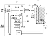
- FIG. 1 is a view showing the configuration of a heating apparatus 100 according to an embodiment of the present invention.
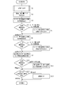
- FIG. 2 is a flowchart showing the process contents of the temperature controller 30, particularly regarding the identification of the transfer function and the determination of the abnormal part.
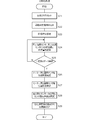
- FIG. 3 is a flowchart showing details of the initialization process (S1) of FIG.
- FIG. 1 is a view showing the configuration of a heating apparatus 100 according to an embodiment of the present invention.
- the heating device 100 includes a heater 10 for heating the object to be heated 1, a temperature detection unit 20 for detecting the temperature of the object to be heated 1, and detection values of the temperature detection unit 20. And a target temperature to control the heater 10 so that the temperature of the object 1 is the target temperature.
- the object to be heated 1 is, for example, a heating unit of a resin heat molding machine such as an injection molding machine or an extrusion molding machine, and the heater 10 and the temperature detection unit 20 are provided in the heating unit of the resin heat molding machine.
- the temperature detection unit 20 is configured of a first temperature sensor 21 and a second temperature sensor 22 in this example.
- the temperature controller 30 is a heat transfer function between the heater 10 and the temperature sensors 21 and 22 from the temperature data detected by the temperature sensors 21 and 22 and the operation amount data corresponding to the electric power applied to the heater 10.
- an identification unit 34 for identifying a heat transfer function between the temperature sensors 21 and 22.
- the temperature controller 30 also includes a determination unit 36 that detects a change from the initial value of the coefficient of the transfer function, and determines an abnormal part of the heater 10 or the temperature sensors 21 and 22 from this change.
- an abnormal part of the heater 10 or the temperature sensors 21 and 22 can be determined.
- FIG. 1 is a view showing the configuration of the heating device 100 according to the embodiment of the present invention.
- the heating device 100 includes a heater 10 for heating the object to be heated 1, a temperature detection unit 20 for detecting the temperature of the object to be heated 1, and detection values and target temperatures of the temperature detection unit 20. And a solid state switch 40 and a heater power supply 50.
- the temperature controller 30 controls the heater 10 so that the temperature of the object 1 to be heated becomes the target temperature.
- the article to be heated 1 is a molded article of metal or the like.
- FIG. 1 is a block diagram, the object to be heated 1 is drawn conceptually, but the actual shape may be appropriately determined.
- the temperature controller 30 includes an A / D converter 31, a PID operation unit 32, a D / A converter 33, an identification unit 34, a setting unit 35, and a determination unit 36.
- Each of the temperature sensors 21 and 22 is, for example, a thermocouple, and is attached to mutually different positions of the object 1 to be heated.
- they are provided inside the nozzle of an injection molding machine, or in the mold of an extrusion molding machine or in the vicinity thereof.
- the A / D converter 31 converts the electromotive force of the temperature sensors 21 and 22 into digital data.
- the PID calculating unit 32 obtains an operation amount by PID calculation based on the target temperature set from the outside and the output value of the A / D converter 31. Since the temperature data subjected to A / D conversion is plural (two in this example), the PID operation unit 32 uses temperature data obtained by statistically processing two temperature data. For example, the average value of two temperature data is used as temperature data used in the PID operation unit 32.
- the PID operation unit 32 outputs the data of the operation amount to the D / A converter 33.
- the D / A converter 33 generates a PWM signal according to the amount of operation. This PWM signal is provided as an on / off signal to the solid state switch 40.
- the identification unit 34 is a heat transfer function between the heater 10 and the temperature sensors 21 and 22 from the temperature data detected by the temperature sensors 21 and 22 and the operation amount data corresponding to the power applied to the heater 10, And the heat transfer function between the temperature sensors 21 and 22.
- the setting unit 35 sets initial values of coefficients of the heat transfer function between the heater 10 and the temperature sensors 21 and 22 and the heat transfer function between the temperature sensors 21 and 22 determined by the identification unit 34. Do. Further, the setting unit 35 sets a threshold setting value input from the outside.
- the determination unit 36 detects a change from the initial value of the transfer function coefficient, and determines an abnormal part of the heater 10 or the temperature sensors 21 and 22 from this change.
- Heater 10 ⁇ heated object 1 ⁇ temperature sensors 21 and 22 ⁇ A / D converter 31 ⁇ PID operation unit 32 ⁇ D / A converter 33 ⁇ solid state switch 40 ⁇ heater 10 loop is a feedback loop shown in FIG.
- the temperature controller 30 By the feedback control of the temperature controller 30, the temperature of the object to be heated is controlled to follow the target temperature.
- FIG. 2 is a flowchart showing the process contents of the temperature controller 30, particularly regarding the identification of the transfer function and the determination of the abnormal part. These processes are processes of the identification unit 34, the setting unit 35, and the determination unit 36 illustrated in FIG.
- initialization processing is performed (S1).
- various flags are reset, and threshold setting values are read. Details of this initialization process will be described later based on FIG.
- the coefficient of the transfer function between the heater 10 and the temperature sensor 21 is compared with the threshold value determined in the initialization process, and the flag F1 is set if the coefficient of the transfer function between the heater 10 and the temperature sensor 21 exceeds the threshold value. (S4 ⁇ S5).
- the heat transfer function (second transfer function) between the heater 10 and the temperature sensor 22 is identified based on the data of the temperature and the operation amount detected by the temperature sensor 22 (S6).
- the coefficient of the second transfer function is compared with the threshold determined in the initialization process, and if there is a fluctuation in the coefficient of the transfer function between the heater 10 and the temperature sensor 22, the flag F2 is set. (S7 ⁇ S8).
- a heat transfer function (third transfer function) between the temperature sensor 21 and the temperature sensor 22 is identified (S9) ).
- the coefficient of the transfer function is compared with the threshold determined in the initialization process, and if there is a fluctuation in the coefficient of the transfer function between the temperature sensor 21 and the temperature sensor 22, the flag F3 is set. (S10 ⁇ S11).
- the series of processes shown in FIG. 2 are repeatedly performed at predetermined time intervals. Alternatively, when the heat treatment is repeatedly performed, the heat treatment is performed every cycle of the heat treatment.
- FIG. 3 is a flowchart showing details of the initialization process (S1) of FIG. First, various flags are reset (S21). Then, the threshold setting value is read from the outside (S22). This is a value indicating the threshold range in proportion, such as ⁇ 10% or ⁇ 15%.
- the target temperature is set to a predetermined value, and the power applied to the heater 10 is changed (S23).
- the temperature of the object to be heated also changes with the lapse of time from the setting of the target temperature.
- the temperature detected by the first temperature sensor 21, the temperature detected by the second temperature sensor 22, and the operation amount output from the PID calculation unit 32 are stored in time series ( S24).
- a heat transfer function between the heater 10 and the first temperature sensor 21 is identified based on data of a constant number of the temperature and the operation amount detected by the first temperature sensor 21. (S25 ⁇ S26). That is, each coefficient of this transfer function is determined.
- the heat transfer function between the heater 10 and the second temperature sensor 22 is identified based on data of a constant of the temperature and the operation amount detected by the second temperature sensor 22 (S27).
- the heat transfer function between the first temperature sensor 21 and the second temperature sensor 22 based on data of a constant of the temperature detected by the first temperature sensor 21 and the temperature detected by the second temperature sensor 22. Are identified (S28).
- each threshold value is determined from the coefficients of each transfer function (S29).
- a transfer function from input to output is obtained, for example, by Fourier transformation of input data as a denominator and output data as a numerator.
- first transfer function first transfer function
- second transfer function time series data (time series data of the operation amount) of the heater 10
- time series data time series data of the operation amount
- the time-series data of the temperature detected by the first temperature sensor 21 corresponds to the above input data
- the time series data of the temperature detected by the second temperature sensor 22 corresponds to the output data.
- the first transfer function, the second transfer function, and the third transfer function are all expressed, for example, as follows.
- f k / ⁇ ( ⁇ 1 ⁇ s + 1) ( ⁇ 2 ⁇ s + 1) ⁇
- k, ⁇ 1 and ⁇ 2 are all coefficients
- k is a proportional gain
- ⁇ 1 and ⁇ 2 are time constants.
- s is the Laplace operator.
- the initial values of the coefficients are, for example, as follows.
- the determination table shown in step S12 of FIG. 2 is, for example, as follows.
- the heater 10 is abnormal.
- This abnormal state is, for example, loose attachment or disconnection of the heater 10 or the like. That is, when the gap between the heater 10 and the object to be heated becomes large due to loose attachment of the heater 10, the temperature change of the object to be heated becomes slow, so that the transfer function between the heater 10 and the first temperature sensor 21 This can be determined as an abnormality of the coefficient and the coefficient of the transfer function between the heater 10 and the second temperature sensor 22.
- the heater 10 is broken, the temperature change of the object to be heated becomes abnormal, so the coefficient of the transfer function between the heater 10 and the first temperature sensor 21 and the transfer function between the heater 10 and the second temperature sensor 22 This appears as an abnormality in the coefficient of, which can be determined.
- the first temperature sensor 21 is abnormal.
- This abnormal state is, for example, loose attachment or disconnection of the first temperature sensor 21. That is, when there is looseness in the attachment of the first temperature sensor 21, the change in temperature detected by the first temperature sensor 21 becomes slow, so the coefficient of the transfer function between the heater 10 and the first temperature sensor 21 and the first temperature sensor This is manifested as an abnormality in the coefficient of the transfer function between the temperature sensor 21 and the second temperature sensor 22, which can be determined. Also, if the first temperature sensor 21 is broken, the temperature is not detected correctly. Therefore, the coefficient of the transfer function between the heater 10 and the first temperature sensor 21 and the transfer function between the first temperature sensor 21 and the second temperature sensor 22 This appears as an abnormality in the coefficient of, which can be determined.
- the second temperature sensor 22 is abnormal.
- This abnormal state is, for example, loose attachment or disconnection of the second temperature sensor 22.
- the threshold value is determined by the ratio (+ 10%, -10%, etc.) of the transfer function coefficient to the initial value, It is not limited to this.
- the difference may be set as a threshold for each coefficient.
- variations such as the standard deviation at the time of normality of each coefficient may be measured, and for example, a triple value thereof may be set as the threshold value.
- the fluctuation range of the coefficient that is permitted within the range in which the control of the temperature controller 30 performs a prescribed operation may be set as the threshold value.
- the operation amount data corresponding to the power applied to the heater 10 is used to identify the transfer function, but the power applied to the heater 10 is directly detected and the data is transferred It may be used for identification of
- the form of the transfer function to be identified is not limited to the above.
- the heat transfer function between the heater 10 and the temperature sensors 21 and 22 may be similar to or different from the actual transfer function. Since the abnormality determination is performed by obtaining each coefficient of the heat transfer function between the heater 10 and the temperature sensors 21 and 22 and comparing them with the threshold value, the transfer function to be identified deviates somewhat from the actual transfer function. However, determination of the presence or absence of an abnormality and determination of an abnormal part are possible.
- the detection value of the temperature sensor may be used to detect the temperature distribution of the object to be heated.
Landscapes
- Physics & Mathematics (AREA)
- General Physics & Mathematics (AREA)
- Engineering & Computer Science (AREA)
- Automation & Control Theory (AREA)
- Injection Moulding Of Plastics Or The Like (AREA)
- Control Of Resistance Heating (AREA)
- Control Of Temperature (AREA)
Abstract
加熱装置(100)は、被加熱物(1)を加熱するヒータ(10)と、被加熱物(1)の温度を検出する温度検出部(20)と、温度検出部(20)の検出値と目標温度とに基づいて被加熱物(1)の温度が目標温度となるようにヒータ(10)を制御する温度調節器(30)とを含む。温度検出部(20)は複数の温度センサ(21,22)で構成される。同定部(34)は、温度センサ(21,22)により検出された温度データと、ヒータ(10)への印加電力に相当する操作量データとから、ヒータ(10)と温度センサ(21,22)との間の熱の伝達関数、および温度センサ(21,22)間の熱の伝達関数を同定する。判定部(36)は、伝達関数の係数の初期値からの変化を検知し、この変化からヒータ(10)または温度センサ(21,22)の異常箇所を判定する。
Description
本発明は、被加熱物を加熱するヒータと、被加熱物の温度を検出する温度検出部とを備える加熱装置に関する。
何らかの被加熱物を加熱する加熱装置は、一般に、被加熱物を加熱するヒータと、被加熱物の温度を検出する温度センサと、温度センサの検出に基づいてヒータを制御する温度調節器とを含む。
上記温度調節器は、温度センサの検出値と目標温度とに基づいて被加熱物の温度が目標温度となるようにヒータをフィードバック制御するので、被加熱物の温度は定常状態で目標温度となる。このような加熱装置は例えば特許文献1,2,3に示されている。
上記ヒータと温度センサを備える加熱装置においては、温度センサによる被加熱体の温度検出が正しく行われ、ヒータによる被加熱物の加熱が正常に行われることが前提であり、これらに異常があると、被加熱物は正しく温度制御されない。
そこで、本発明の目的は、温度センサによる被加熱体の温度検出が正しく行われる状態であるか、ヒータによる被加熱物の加熱が正常に行われる状態であるか、を判定可能とした加熱装置を提供することにある。
本開示の一例としての加熱装置は、被加熱物を加熱するヒータと、被加熱物の温度を検出する温度検出部と、温度検出部の検出値と目標温度とに基づいて被加熱物の温度が目標温度となるようにヒータを制御する温度調節器とを含む加熱装置であって、
温度検出部は複数の温度センサで構成され、
複数の温度センサにより検出された温度データと、ヒータへの印加電力またはこの印加電力に相当する操作量データとから、ヒータと複数の温度センサとの間の熱の伝達関数、および複数の温度センサ間の熱の伝達関数を含む複数の伝達関数を同定する同定部と、これら複数の伝達関数の係数の初期値からの変化を検知し、この変化からヒータまたは複数の温度センサの異常箇所を判定する判定部と、を備える。
温度検出部は複数の温度センサで構成され、
複数の温度センサにより検出された温度データと、ヒータへの印加電力またはこの印加電力に相当する操作量データとから、ヒータと複数の温度センサとの間の熱の伝達関数、および複数の温度センサ間の熱の伝達関数を含む複数の伝達関数を同定する同定部と、これら複数の伝達関数の係数の初期値からの変化を検知し、この変化からヒータまたは複数の温度センサの異常箇所を判定する判定部と、を備える。
この構成では、ヒータまたは複数の温度センサの異常箇所を判定することができる。
また、本開示の一例では、前記判定部は、伝達関数の係数の初期値からの変化量と閾値との比較によって伝達関数の変化の有無を検知する。
この構成では、伝達関数の初期値からの変化の有無の検知が容易となり、ヒータまたは複数の温度センサの異常箇所の判定が容易となる。
また、本開示の一例では、前記閾値は、伝達関数の係数の初期値に対する比率によって定められたものである。
この構成では、伝達関数の複数の係数について均等に、それらの変化の異常性が検知されて、ヒータまたは複数の温度センサの異常箇所の判定が、より正確なものとなる。
また、本開示の一例では、前記被加熱物は、樹脂加熱成形機の加熱部であり、この加熱部にヒータおよび温度検出部が設けられる。
この構成では、射出成形機や押し出し成形機等において、ヒータや温度検出部の異常による不良品の成形を未然に防止できる。
本発明によれば、温度センサによる被加熱体の温度検出が正しく行われる状態であるか、ヒータによる被加熱物の加熱が正常に行われる状態であるか、が判定できるので、結果的に信頼性の高い加熱装置が得られる。
以下、本発明を実施するための形態について、幾つかの図を参照して説明する。
・適用例
先ず、図1を参照しながら、本発明が適用される一例について説明する。図1は本発明の実施形態に係る加熱装置100の構成を示す図である。
先ず、図1を参照しながら、本発明が適用される一例について説明する。図1は本発明の実施形態に係る加熱装置100の構成を示す図である。
図1に示すように、本実施形態に係る加熱装置100は、被加熱物1を加熱するヒータ10と、被加熱物1の温度を検出する温度検出部20と、温度検出部20の検出値と目標温度とに基づいて被加熱物1の温度が目標温度となるようにヒータ10を制御する温度調節器30とを含む。
被加熱物1は、例えば射出成形機や押し出し成形機等の樹脂加熱成形機の加熱部であり、ヒータ10および温度検出部20は樹脂加熱成形機の加熱部に設けられる。
温度検出部20は、この例では、第1温度センサ21と第2温度センサ22とで構成される。温度調節器30は、温度センサ21,22により検出された温度データと、ヒータ10への印加電力に相当する操作量データとから、ヒータ10と温度センサ21,22との間の熱の伝達関数、および温度センサ21,22間の熱の伝達関数を同定する同定部34を備える。
また、温度調節器30は、上記伝達関数の係数の初期値からの変化を検知し、この変化からヒータ10または温度センサ21,22の異常箇所を判定する判定部36を備える。
この構成では、ヒータ10または温度センサ21,22の異常箇所を判定することができる。
・構成例
次に、本発明の実施形態に係る加熱装置の構成について、図を参照して説明する。上述のように、図1は本発明の実施形態に係る加熱装置100の構成を示す図である。
次に、本発明の実施形態に係る加熱装置の構成について、図を参照して説明する。上述のように、図1は本発明の実施形態に係る加熱装置100の構成を示す図である。
図1に表れているように、加熱装置100は、被加熱物1を加熱するヒータ10と、被加熱物1の温度を検出する温度検出部20と、温度検出部20の検出値と目標温度とに基づいて被加熱物1の温度が目標温度となるようにヒータ10を制御する温度調節器30と、ソリッドステートスイッチ40と、ヒータ電源50とを備える。被加熱物1は金属等の成形体である。図1はブロック構成図であるので、被加熱物1は概念的に描いているが、実際の形状は適宜定められる。
温度調節器30は、A/Dコンバータ31、PID演算部32、D/Aコンバータ33、同定部34、設定部35、および判定部36を含む。
温度センサ21,22はそれぞれ例えば熱電対であり、被加熱物1の、互いに異なる位置に取り付けられている。例えば、射出成形機のノズルの内部や、押し出し成形機の金型またはその近傍に設けられている。
A/Dコンバータ31は温度センサ21,22の起電力をそれぞれデジタルデータに変換する。PID演算部32は、外部から設定される目標温度とA/Dコンバータ31の出力値とに基づいて、PID演算により操作量を求める。A/D変換された温度データは複数(この例では二つ)であるので、PID演算部32は二つの温度データを統計処理して求めた温度データを使用する。例えば、二つの温度データの平均値をPID演算部32で用いる温度データとする。PID演算部32は上記操作量のデータをD/Aコンバータ33へ出力する。D/Aコンバータ33は操作量に応じたPWM信号を発生する。このPWM信号はソリッドステートスイッチ40に対するon/off信号として与えられる。
同定部34は、温度センサ21,22により検出された温度データと、ヒータ10への印加電力に相当する操作量データとから、ヒータ10と温度センサ21,22との間の熱の伝達関数、および温度センサ21,22間の熱の伝達関数を同定する。
設定部35は、同定部34で求められた、ヒータ10と温度センサ21,22との間の熱の伝達関数、および温度センサ21,22間の熱の伝達関数の各係数の初期値を設定する。また、設定部35は外部から入力される閾値設定値を設定する。
判定部36は、伝達関数の係数の初期値からの変化を検知し、この変化からヒータ10または温度センサ21,22の異常箇所を判定する。
図1に示した、ヒータ10→被加熱物1→温度センサ21,22→A/Dコンバータ31→PID演算部32→D/Aコンバータ33→ソリッドステートスイッチ40→ヒータ10のループはフィードバックループを構成し、温度調節器30のフィードバック制御により、被加熱物の温度が目標温度に追従するように制御される。
図2は、温度調節器30の、特に伝達関数の同定と、異常箇所の判定に関する処理内容を示すフローチャートである。これらの処理は、図1に示した同定部34、設定部35、および判定部36の処理である。
先ず、初期化処理が行われる(S1)。この初期化処理で各種フラグがリセットされ、閾値設定値が読み込まれる。この初期化処理の詳細は、図3を基に後述する。
その後、温度センサ21により検出された温度と操作量のデータを読み込み、温度と操作量のデータに基づいて、ヒータ10と温度センサ21との間の熱の伝達関数(第1伝達関数)を同定する(S2→S3)。
上記第1伝達関数の係数と、上記初期化処理で定められた閾値とを比較し、ヒータ10と温度センサ21との間の伝達関数の係数に閾値を超える変動があれば、フラグF1をセットする(S4→S5)。
次に、温度センサ22により検出された温度と操作量のデータに基づいて、ヒータ10と温度センサ22との間の熱の伝達関数(第2伝達関数)を同定する(S6)。
上記第2伝達関数の係数と、上記初期化処理で定められた閾値とを比較し、ヒータ10と温度センサ22との間の伝達関数の係数に閾値を超える変動があれば、フラグF2をセットする(S7→S8)。
また、温度センサ21により検出された温度と温度センサ22により検出された温度とに基づいて、温度センサ21と温度センサ22との間の熱の伝達関数(第3伝達関数)を同定する(S9)。
上記伝達関数の係数と、上記初期化処理で定められた閾値とを比較し、温度センサ21と温度センサ22との間の伝達関数の係数に閾値を超える変動があれば、フラグF3をセットする(S10→S11)。
その後、上記フラグF1,F2,F3と、後に示す判定表と、に基づいて、ヒータ10、第1温度センサ21、第2温度センサ22の異常有無と異常箇所を判定する。異常があれば、その旨を示す警報処理を行う(S12→S13)。例えば、「ヒータの異常」、「第1温度センサの異常」、「第2温度センサの異常」、といった表示を行う。
その後、次の処理へ進む。図2に示した一連の処理は、所定時間間隔で繰り返し実行される。または、加熱処理を繰り返し行う場合に、加熱処理の周期毎に実行される。
図3は、図2の初期化処理(S1)の詳細を示すフローチャートである。先ず、各種フラグをリセットする(S21)。そして、外部から閾値設定値を読み込む(S22)。これは例えば±10%や±15%といった、閾値範囲を比率で示す値である。
次に、目標温度を所定値に定めて、ヒータ10への印加電力を変化させる(S23)。
目標温度の変更により、ヒータ10への印加電力が変化するので、目標温度の設定からの時間経過に伴って被加熱物の温度も変化する。この過渡時の、第1温度センサ21により検出された温度と、第2温度センサ22により検出された温度と、PID演算部32から出力された操作量とを時系列的に記憶していく(S24)。
一定数のデータが蓄積されれば、第1温度センサ21の検出による温度と操作量との一定数のデータに基づいて、ヒータ10と第1温度センサ21との間の熱の伝達関数を同定する(S25→S26)。つまり、この伝達関数の各係数を求める。同様に、第2温度センサ22の検出による温度と操作量との一定数のデータに基づいて、ヒータ10と第2温度センサ22との間の熱の伝達関数を同定する(S27)。また、第1温度センサ21の検出による温度と第2温度センサ22の検出による温度との一定数のデータに基づいて、第1温度センサ21と第2温度センサ22との間の熱の伝達関数を同定する(S28)。
その後、各伝達関数の係数から各閾値を決定する(S29)。
一般に、入力から出力までの伝達関数は、例えば入力データを分母、出力データを分子としてフーリエ変換することにより得られる。本実施形態では、例えばヒータ10と第1温度センサ21との間の熱の伝達関数(第1伝達関数)を同定する場合、ヒータ10の時系列データ(操作量の時系列データ)が上記入力データに対応し、第1温度センサ21の検出温度の時系列データが上記出力データに対応する。同様に、ヒータ10と第2温度センサ22との間の熱の伝達関数(第2伝達関数)を同定する場合、ヒータ10の時系列データ(操作量の時系列データ)が上記入力データに対応し、第2温度センサ22の検出温度の時系列データが上記出力データに対応する。また、第1温度センサ21と第2温度センサ22との間の熱の伝達関数(第3伝達関数)を同定する場合、第1温度センサ21の検出温度の時系列データが上記入力データに対応し、第2温度センサ22の検出温度の時系列データが上記出力データに対応する。
上記第1伝達関数、第2伝達関数、第3伝達関数は、いずれも例えば次のように表される。
f=k/{(τ1・s+1)(τ2・s+1)}
ここでk、τ1、τ2、はいずれも係数であり、kは比例ゲイン、τ1、τ2は時定数である。また、sはラプラス演算子である。
ここでk、τ1、τ2、はいずれも係数であり、kは比例ゲイン、τ1、τ2は時定数である。また、sはラプラス演算子である。
初期状態の各係数k = 1000℃、τ1 = 10、τ2= 100、で、閾値設定値が±10%であれば、各係数の初期値は例えば次のとおりである。

図2のステップS12に示した判定表は例えば次のとおりである。
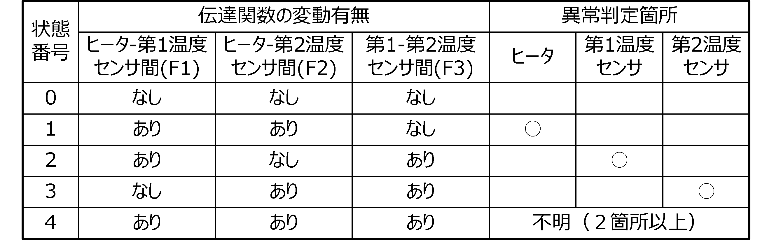
例えば、フラグF3がリセット状態のままで、フラグF1,F2がセットされていれば、ヒータ10の異常と判定する。この異常状態は、例えばヒータ10の取り付け緩みや断線等である。すなわち、ヒータ10の取り付け緩みに起因して、ヒータ10と被加熱物との間隙が大きくなると、被加熱物の温度変化が緩慢となるので、ヒータ10と第1温度センサ21間の伝達関数の係数、およびヒータ10と第2温度センサ22間の伝達関数の係数の異常となって現れ、このことが判定できる。また、ヒータ10に断線があると、被加熱物の温度変化が異常となるので、ヒータ10と第1温度センサ21間の伝達関数の係数、およびヒータ10と第2温度センサ22間の伝達関数の係数の異常となって現れ、このことが判定できる。
また、例えば、フラグF2がリセット状態のままで、フラグF1,F3がセットされていれば、第1温度センサ21の異常と判定する。この異常状態は、例えば第1温度センサ21の取り付け緩みや断線等である。すなわち、第1温度センサ21の取り付け緩みがあると、第1温度センサ21による検出温度の変化が緩慢となるので、ヒータ10と第1温度センサ21間の伝達関数の係数、および第1温度センサ21と第2温度センサ22間の伝達関数の係数の異常となって現れ、このことが判定できる。また、第1温度センサ21に断線があると、正しく温度検出されないので、ヒータ10と第1温度センサ21間の伝達関数の係数、および第1温度センサ21と第2温度センサ22間の伝達関数の係数の異常となって現れ、このことが判定できる。
同様に、例えば、フラグF1がリセット状態のままで、フラグF2,F3がセットされていれば、第2温度センサ22の異常と判定する。この異常状態は、例えば第2温度センサ22の取り付け緩みや断線等である。
また、例えば、フラグF1,F2,F3のいずれもセットされていれば、ヒータ10、温度センサ21,22のうち二つ以上に異常があるものと判定する。つまりこの状態では、異常箇所までは判定できないが、異常の有無は判定できる。
上述の例では、伝達関数の係数の変化量が閾値を超えるか否かを検知するために、伝達関数の係数の初期値に対する比率(+10%や-10%等)によって閾値を定めたが、これに限らない。例えば、係数毎に差分を閾値として定めてもよい。
また、各係数の正常時の標準偏差等のばらつきを実測し、例えば、その3倍の値を閾値として定めてもよい。また、温度調節器30の制御が規定の動作を行う範囲で許容される係数の変動幅を閾値として設定してもよい。
また、係数の絶対値が閾値を超えるか否かの検知ではなく、時間経過あたりの係数の変化量が閾値を超えるか否かを検知してもよい。このことにより、ヒータ10、温度センサ21,22の取り付け状態の急激な変化を応答性良く検知できる。
図1に示した例では、ヒータ10への印加電力に相当する操作量データを、伝達関数の同定に用いたが、ヒータ10への印加電力を直接的に検出して、そのデータを伝達関数の同定に用いてもよい。
最後に、上述の発明を実施するための形態の説明は、改めて述べるまでもなく、すべての点で例示であって、制限的なものではない。当業者にとって変形および変更が適宜可能である。
例えば、同定を行う伝達関数の形についても、上記のものに限らない。ヒータ10と温度センサ21,22との間の熱の伝達関数が実際の伝達関数とは近似していればよく、異なっていてもよい。ヒータ10と温度センサ21,22との間の熱の伝達関数の各係数を求め、それらと閾値と比較することで異常判定を行うので、同定を行う伝達関数が実際の伝達関数から多少ずれていても、異常有無の判定および異常箇所の判定は可能である。
また、以上に示した実施形態では、二つの温度センサを備える加熱装置について例示したが、三つ以上の温度センサを備える場合にも同様に適用できる。
また、複数の温度センサを備え、複数の温度センサの間隔が大きい場合、温度センサによる検出値を、被加熱物の温度分布を検知することに利用してもよい。
1…被加熱物
10…ヒータ
20…温度検出部
21…第1温度センサ
22…第2温度センサ
30…温度調節器
31…A/Dコンバータ
32…PID演算部
33…D/Aコンバータ
34…同定部
35…設定部
36…判定部
40…ソリッドステートスイッチ
50…ヒータ電源
100…加熱装置
10…ヒータ
20…温度検出部
21…第1温度センサ
22…第2温度センサ
30…温度調節器
31…A/Dコンバータ
32…PID演算部
33…D/Aコンバータ
34…同定部
35…設定部
36…判定部
40…ソリッドステートスイッチ
50…ヒータ電源
100…加熱装置
Claims (4)
- 被加熱物を加熱するヒータと、前記被加熱物の温度を検出する温度検出部と、前記温度検出部の検出値と目標温度とに基づいて前記被加熱物の温度が前記目標温度となるように前記ヒータを制御する温度調節器とを含む加熱装置であって、
前記温度検出部は複数の温度センサで構成され、
前記複数の温度センサにより検出された温度データと、前記ヒータへの印加電力または当該印加電力に相当する操作量データとから、前記ヒータと前記複数の温度センサとの間の熱の伝達関数、および前記複数の温度センサ間の熱の伝達関数を含む複数の伝達関数を同定する同定部と、
前記複数の伝達関数の係数の初期値からの変化を検知し、当該変化から前記ヒータまたは前記複数の温度センサの異常箇所を判定する判定部と、
を備える加熱装置。 - 前記判定部は、前記初期値からの変化量と閾値との比較によって前記伝達関数の係数の変化の有無を検知する、請求項1に記載の加熱装置。
- 前記閾値は、前記伝達関数の係数の前記初期値に対する比率によって定められたものである、請求項2に記載の加熱装置。
- 前記被加熱物は、樹脂加熱成形機の加熱部であり、前記ヒータおよび前記温度検出部は前記加熱部に設けられる、請求項1から3のいずれかに記載の加熱装置。
Priority Applications (3)
| Application Number | Priority Date | Filing Date | Title |
|---|---|---|---|
| US16/639,739 US11602011B2 (en) | 2018-01-09 | 2018-12-20 | Heating device |
| EP18899311.7A EP3740029B1 (en) | 2018-01-09 | 2018-12-20 | Heating device |
| CN201880053366.1A CN111034351B (zh) | 2018-01-09 | 2018-12-20 | 加热装置 |
Applications Claiming Priority (2)
| Application Number | Priority Date | Filing Date | Title |
|---|---|---|---|
| JP2018-000998 | 2018-01-09 | ||
| JP2018000998A JP6874696B2 (ja) | 2018-01-09 | 2018-01-09 | 加熱装置 |
Publications (1)
| Publication Number | Publication Date |
|---|---|
| WO2019138830A1 true WO2019138830A1 (ja) | 2019-07-18 |
Family
ID=67219705
Family Applications (1)
| Application Number | Title | Priority Date | Filing Date |
|---|---|---|---|
| PCT/JP2018/046936 Ceased WO2019138830A1 (ja) | 2018-01-09 | 2018-12-20 | 加熱装置 |
Country Status (6)
| Country | Link |
|---|---|
| US (1) | US11602011B2 (ja) |
| EP (1) | EP3740029B1 (ja) |
| JP (1) | JP6874696B2 (ja) |
| CN (1) | CN111034351B (ja) |
| TW (1) | TWI697749B (ja) |
| WO (1) | WO2019138830A1 (ja) |
Families Citing this family (4)
| Publication number | Priority date | Publication date | Assignee | Title |
|---|---|---|---|---|
| JP6874719B2 (ja) * | 2018-03-02 | 2021-05-19 | オムロン株式会社 | 加熱装置及び加熱装置の異常検知方法 |
| CN113966644B (zh) * | 2019-06-07 | 2025-11-04 | 沃特洛电气制造公司 | 用于校准操作电加热器的控制系统的系统和方法 |
| US12222250B2 (en) * | 2019-10-30 | 2025-02-11 | Illinois Tool Works Inc. | Methods and apparatus to control heating based on monitoring feedback of temperature sensors |
| JP6933286B1 (ja) * | 2020-09-17 | 2021-09-08 | オムロン株式会社 | 温度制御方法、温度制御装置およびプログラム |
Citations (9)
| Publication number | Priority date | Publication date | Assignee | Title |
|---|---|---|---|---|
| JPS6127110A (ja) * | 1984-07-17 | 1986-02-06 | Kawasaki Steel Corp | 油圧圧下式圧延機における故障診断方法 |
| JPH0346013A (ja) * | 1989-07-13 | 1991-02-27 | Nec Corp | 温度異常検出回路 |
| JPH0612133A (ja) | 1992-06-25 | 1994-01-21 | Sanyo Electric Co Ltd | 恒温庫の温度制御装置 |
| JPH08166826A (ja) | 1994-12-14 | 1996-06-25 | Omron Corp | リレー異常検出回路、制御装置および温度調節器 |
| JPH09198147A (ja) * | 1996-01-23 | 1997-07-31 | Omron Corp | 温度調節器 |
| JPH09198148A (ja) * | 1996-01-23 | 1997-07-31 | Tokyo Electron Ltd | 熱処理装置の制御パラメータの決定装置及びその方法 |
| JPH1154244A (ja) * | 1997-08-01 | 1999-02-26 | Kokusai Electric Co Ltd | 熱処理炉の加熱用ヒータ断線検出方法及びその装置 |
| JP2002124481A (ja) * | 2001-05-28 | 2002-04-26 | Hitachi Kokusai Electric Inc | 温度制御シミュレーション方法および温度制御シミュレーション装置 |
| JP2011193148A (ja) | 2010-03-12 | 2011-09-29 | Omron Corp | Ad変換器、ad変換方法、および温度調節器 |
Family Cites Families (8)
| Publication number | Priority date | Publication date | Assignee | Title |
|---|---|---|---|---|
| JPH0661811B2 (ja) | 1989-11-24 | 1994-08-17 | 東芝機械株式会社 | 加熱温度制御装置 |
| JPH06330747A (ja) * | 1993-05-26 | 1994-11-29 | Kubota Corp | インライン形熱交換器の診断方法 |
| TW518639B (en) * | 1999-11-18 | 2003-01-21 | Tokyo Electron Ltd | Heat treatment device, cooling treatment device and cooling treatment method |
| WO2001079943A1 (en) * | 2000-04-14 | 2001-10-25 | Omron Corporation | Controller, temperature regulator, and heat treatment apparatus |
| JP5428525B2 (ja) | 2009-05-22 | 2014-02-26 | 富士電機株式会社 | 精密温調システム、その制御装置 |
| DE102009047664B4 (de) | 2009-12-08 | 2017-03-02 | Endress + Hauser Wetzer Gmbh + Co. Kg | Messeinrichtung zur Bestimmung einer Wärmemenge |
| CN104048993B (zh) * | 2014-06-27 | 2017-01-25 | 吉林大学 | 便携式原位浅层地温和导热系数测量装置及测试方法 |
| JP6320200B2 (ja) * | 2014-07-01 | 2018-05-09 | アズビル株式会社 | Pidコントローラおよびデータ収集方法 |
-
2018
- 2018-01-09 JP JP2018000998A patent/JP6874696B2/ja active Active
- 2018-12-18 TW TW107145690A patent/TWI697749B/zh active
- 2018-12-20 CN CN201880053366.1A patent/CN111034351B/zh active Active
- 2018-12-20 EP EP18899311.7A patent/EP3740029B1/en active Active
- 2018-12-20 US US16/639,739 patent/US11602011B2/en active Active
- 2018-12-20 WO PCT/JP2018/046936 patent/WO2019138830A1/ja not_active Ceased
Patent Citations (9)
| Publication number | Priority date | Publication date | Assignee | Title |
|---|---|---|---|---|
| JPS6127110A (ja) * | 1984-07-17 | 1986-02-06 | Kawasaki Steel Corp | 油圧圧下式圧延機における故障診断方法 |
| JPH0346013A (ja) * | 1989-07-13 | 1991-02-27 | Nec Corp | 温度異常検出回路 |
| JPH0612133A (ja) | 1992-06-25 | 1994-01-21 | Sanyo Electric Co Ltd | 恒温庫の温度制御装置 |
| JPH08166826A (ja) | 1994-12-14 | 1996-06-25 | Omron Corp | リレー異常検出回路、制御装置および温度調節器 |
| JPH09198147A (ja) * | 1996-01-23 | 1997-07-31 | Omron Corp | 温度調節器 |
| JPH09198148A (ja) * | 1996-01-23 | 1997-07-31 | Tokyo Electron Ltd | 熱処理装置の制御パラメータの決定装置及びその方法 |
| JPH1154244A (ja) * | 1997-08-01 | 1999-02-26 | Kokusai Electric Co Ltd | 熱処理炉の加熱用ヒータ断線検出方法及びその装置 |
| JP2002124481A (ja) * | 2001-05-28 | 2002-04-26 | Hitachi Kokusai Electric Inc | 温度制御シミュレーション方法および温度制御シミュレーション装置 |
| JP2011193148A (ja) | 2010-03-12 | 2011-09-29 | Omron Corp | Ad変換器、ad変換方法、および温度調節器 |
Non-Patent Citations (1)
| Title |
|---|
| See also references of EP3740029A4 |
Also Published As
| Publication number | Publication date |
|---|---|
| JP6874696B2 (ja) | 2021-05-19 |
| EP3740029A1 (en) | 2020-11-18 |
| EP3740029A4 (en) | 2021-09-29 |
| TWI697749B (zh) | 2020-07-01 |
| US20200187304A1 (en) | 2020-06-11 |
| US11602011B2 (en) | 2023-03-07 |
| CN111034351A (zh) | 2020-04-17 |
| TW201931042A (zh) | 2019-08-01 |
| JP2019121522A (ja) | 2019-07-22 |
| EP3740029B1 (en) | 2022-05-11 |
| CN111034351B (zh) | 2022-04-12 |
Similar Documents
| Publication | Publication Date | Title |
|---|---|---|
| CN111034351B (zh) | 加热装置 | |
| TWI743739B (zh) | 具備溫度限制裝置之熱系統 | |
| JP5983765B2 (ja) | 調節器、制御方法および制御プログラム | |
| JP6874719B2 (ja) | 加熱装置及び加熱装置の異常検知方法 | |
| KR20180089271A (ko) | Pid 제어 장치, pid 제어 방법 및 pid 제어 프로그램 | |
| WO2021246524A1 (ja) | 射出成形機の制御装置及びプログラム | |
| TW201837636A (zh) | 劣化診斷裝置以及方法 | |
| US20190159366A1 (en) | Temperature control device and method thereof | |
| CN117628872A (zh) | 一种多反馈烘箱加热系统及控制方法 | |
| JP7844436B2 (ja) | システム制御および診断を改善するために中間データを使用するためのシステムおよび方法 | |
| JP7109728B2 (ja) | 電力制御装置及び電力制御方法 | |
| JP6874379B2 (ja) | 制御装置、制御方法、制御プログラム | |
| JP5811035B2 (ja) | 電動射出成形機の負荷状況表示方法、及び電動射出成形機の駆動装置 | |
| JP5328303B2 (ja) | 光学素子の製造装置及びその製造方法 | |
| TW201925968A (zh) | 溫度控制裝置及其方法 | |
| JP2006099352A (ja) | 温度推定装置およびこれを用いた制御装置 | |
| JP3234001B2 (ja) | 加硫機の温度制御装置 | |
| JP2662197B2 (ja) | 厚み制御装置 | |
| KR101517791B1 (ko) | 이화학실험장치의 온도콘트롤러 과온 경보장치 | |
| JP3233984B2 (ja) | 加硫機の温度制御装置 | |
| JP2002257479A (ja) | 熱処理炉及びその加熱制御装置 |
Legal Events
| Date | Code | Title | Description |
|---|---|---|---|
| 121 | Ep: the epo has been informed by wipo that ep was designated in this application |
Ref document number: 18899311 Country of ref document: EP Kind code of ref document: A1 |
|
| NENP | Non-entry into the national phase |
Ref country code: DE |
|
| ENP | Entry into the national phase |
Ref document number: 2018899311 Country of ref document: EP Effective date: 20200810 |