WO2019142842A1 - 光ファイバテープ心線の製造方法および製造装置 - Google Patents
光ファイバテープ心線の製造方法および製造装置 Download PDFInfo
- Publication number
- WO2019142842A1 WO2019142842A1 PCT/JP2019/001174 JP2019001174W WO2019142842A1 WO 2019142842 A1 WO2019142842 A1 WO 2019142842A1 JP 2019001174 W JP2019001174 W JP 2019001174W WO 2019142842 A1 WO2019142842 A1 WO 2019142842A1
- Authority
- WO
- WIPO (PCT)
- Prior art keywords
- optical fiber
- release agent
- resin
- applying
- intermittently
- Prior art date
- Legal status (The legal status is an assumption and is not a legal conclusion. Google has not performed a legal analysis and makes no representation as to the accuracy of the status listed.)
- Ceased
Links
Images


Classifications
-
- G—PHYSICS
- G02—OPTICS
- G02B—OPTICAL ELEMENTS, SYSTEMS OR APPARATUS
- G02B6/00—Light guides; Structural details of arrangements comprising light guides and other optical elements, e.g. couplings
- G02B6/44—Mechanical structures for providing tensile strength and external protection for fibres, e.g. optical transmission cables
- G02B6/4401—Optical cables
- G02B6/4403—Optical cables with ribbon structure
-
- G—PHYSICS
- G02—OPTICS
- G02B—OPTICAL ELEMENTS, SYSTEMS OR APPARATUS
- G02B6/00—Light guides; Structural details of arrangements comprising light guides and other optical elements, e.g. couplings
- G02B6/44—Mechanical structures for providing tensile strength and external protection for fibres, e.g. optical transmission cables
- G02B6/4479—Manufacturing methods of optical cables
- G02B6/448—Ribbon cables
Definitions
- the present disclosure relates to a method and an apparatus for manufacturing an optical fiber ribbon.
- This application claims priority based on Japanese Patent Application No. 2018-006308 filed on Jan. 18, 2018, and incorporates the entire contents described in the aforementioned Japanese application.
- Patent Document 1 optical fibers of three or more cores are arranged in parallel, and two optical fibers adjacent to each other are connected by a connecting portion, and the connecting portion is in the tape core longitudinal direction and the tape core.
- Optical fiber ribbons provided intermittently in the width direction are described.
- Patent Document 2 an application roll having a space inside and having a plurality of application holes communicating with the space on the outer peripheral surface, a pressure unit disposed in the space, and an adhesive member supplied to the space
- An optical fiber ribbon cable manufacturing apparatus having an adhesive member supply unit is described. Then, using the manufacturing apparatus, an adhesive member is intermittently applied between a plurality of the optical fiber strands aligned at a predetermined interval, and an intermittent connection type optical fiber is used to adhere the optical fiber strands to each other.
- a method of making the tape core is described.
- a release agent is used to prevent adhesion between the optical fibers with the connection resin in a state in which a plurality of optical fibers are arranged in parallel.
- Release agent application process applied intermittently to the After the releasing agent applying step, a connecting resin applying step of passing a plurality of optical fibers arranged in parallel through a die for applying a connecting resin around the optical fibers to cure the connecting resin;
- Have An intermittently coupled optical fiber ribbon having a coupling portion and a non-coupling portion is manufactured.
- the manufacturing apparatus of the optical fiber ribbon intermittently releases a release agent for preventing bonding between the optical fibers with the connection resin in a state where a plurality of optical fibers are arranged in parallel.
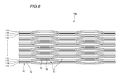
- FIG. 4B is a cross-sectional view taken along line AA of FIG. 4A. It is a figure which shows an example of the screen version shown by FIG. 4A and 4B. It is a figure which shows another example of the optical fiber tape ribbon manufactured with the manufacturing method and manufacturing apparatus of an optical fiber tape ribbon.
- connection resin when the connection resin is applied intermittently, for example, between the coating holes such as a coating roll or the like described in Patent Document 2 and between the optical fibers.
- the connection resin since the viscosity of the connection resin is generally high, there may be a case where the connection resin swells or an application abnormality due to a resin reservoir.
- the connection resin in the conventional method of manufacturing the intermittent connection type optical fiber ribbon, it is difficult to apply the connection resin with high accuracy between the optical fibers.
- An object of the present disclosure is to provide a method and an apparatus for manufacturing an optical fiber ribbon capable of manufacturing an optical fiber ribbon having an intermittent connection structure efficiently and accurately.
- an optical fiber ribbon having an intermittent connection type structure can be manufactured efficiently and accurately.
- a method of manufacturing an optical fiber ribbon according to an aspect of the present disclosure is (1) A release agent application step of intermittently applying a release agent for preventing adhesion between the optical fibers with the connecting resin in a state where a plurality of optical fibers are arranged in parallel, in the longitudinal direction of the optical fiber; After the releasing agent applying step, a connecting resin applying step of passing a plurality of optical fibers arranged in parallel through a die for applying a connecting resin around the optical fibers to cure the connecting resin; Have An intermittently coupled optical fiber ribbon having a coupling portion and a non-coupling portion is manufactured.
- the release agent may be intermittently applied thinly on the surface of the optical fiber in the release agent applying step.
- the release agent may have a viscosity lower than that of the connecting resin. Therefore, the method of manufacturing an optical fiber ribbon can increase the linear velocity of the manufacturing apparatus more than when applying the coupling resin intermittently.
- the intermittent pattern can be formed more accurately on the optical fiber in the state where a plurality of mold release agents are arranged in parallel than the coupling resin.
- the optical fiber is passed through a die for applying the connection resin, so that the optical fibers are bonded with the connection resin and the connection is made between the portions where the release agent is not applied. It becomes a part.
- the portion where the release agent is applied is not bonded between the optical fibers by the connecting resin, and becomes a non-connecting portion.
- the mold release agent applying step may be a step of intermittently supplying and applying the mold release agent from the surface of the plurality of optical fibers arranged in parallel. According to the above method, the release agent can be intermittently applied by intermittently supplying the release agent from the surface of the optical fiber.
- the release agent applying step may be a step of applying the release agent through a screen plate having a pattern in which holes are intermittently opened. According to the above method, since the mechanism for intermittently supplying the release agent is not necessary, the linear velocity of the manufacturing apparatus can be further increased. Further, by forming the intermittent pattern in advance by the screen plate, it is possible to easily form the intermittent connection type optical fiber tape core of different intermittent pattern only by changing the screen plate.
- the release agent may contain silicone.
- the release agent may be a fluorine compound.
- the release agent may contain an alcohol.
- an apparatus for manufacturing an optical fiber ribbon is: (7) A release agent application unit for intermittently applying a release agent for preventing adhesion between optical fibers with a connecting resin in a state where a plurality of optical fibers are arranged in parallel; A connecting resin application unit for passing the plurality of optical fibers to which a releasing agent is applied intermittently through a die for applying a connecting resin around the optical fibers and curing the connecting resin; Have An intermittently coupled optical fiber ribbon having a coupling portion and a non-coupling portion is manufactured. According to the above configuration, since the release agent is intermittently applied by the release agent applying unit, the linear velocity of the production device can be increased at the time of production as compared with the device for applying the coupling resin intermittently.
- the intermittent pattern can be formed more accurately on the optical fiber in the state where a plurality of mold release agents are arranged in parallel than the coupling resin.
- the release agent is applied by passing a plurality of optical fibers in a state in which the release agent is applied intermittently and arranged in parallel through a die for applying the connection resin around the optical fibers of the connection resin application portion.
- the optical fibers are bonded with a connecting resin to form a connecting part.
- the portion where the release agent is applied is not bonded between the optical fibers by the connecting resin, and becomes a non-connecting portion.
- mold structure can be manufactured efficiently and accurately.
- FIG. 1 shows an apparatus 1A for manufacturing an optical fiber ribbon according to a first embodiment of the present disclosure (hereinafter abbreviated as a manufacturing apparatus 1A).
- the manufacturing apparatus 1A includes a supply bobbin portion 2, a guide roller 3A, a positioning die 3B, a release agent applying portion 4, a die 5 constituting a connected resin applying portion, and a resin curing device 6 , A speed sensor 7, a control unit 8, and a winding bobbin 9.
- the supply bobbin portion 2 is composed of N supply bobbins 21, and a single optical fiber core wire 11 is wound around each supply bobbin 21.
- N is the number of optical fibers 11 constituting the optical fiber ribbon.
- N 12.
- the optical fiber cores 11 are supplied from the respective supply bobbins 21 so as to have the same traveling speed (linear speed).
- the guide roller 3A is a roller that guides the plurality of optical fiber cores 11 supplied from the supply bobbin 21 in parallel and guiding them to the positioning die 3B.
- the positioning die 3B is a die for determining the traveling position on the pass line P of the plurality of optical fiber cores 11 sent from the guide roller 3A.
- the release agent coating unit 4 is disposed downstream of the positioning die 3 B, and is configured of a plurality of coating devices that apply the release agent between the optical fiber cores 11.
- the term "mold release agent" as used herein includes materials and the like that weaken the adhesive force of the connecting resin, and generically refers to drugs and the like for preventing adhesion between optical fiber cores with the connecting resin.
- the release agent a drug containing silicone, a fluorine compound, an alcohol or the like is used as the release agent.
- connection resin coating unit is disposed downstream of the release agent coating unit 4 and is coated with a die 5 that applies a connection resin for connecting the optical fiber cores 11 to each other around the optical core 11. It is comprised with the resin-hardening apparatus 6 which hardens connection resin.
- the speed sensor 7 is a sensor that detects the traveling speed of the optical fiber core wire 11 supplied from the supply bobbin 21.
- the speed sensor 7 transmits the detected traveling speed of the optical fiber 11 to the control unit 8.
- the control unit 8 controls the application amount of the release agent in the release agent application unit 4, the interval for applying the release agent, and the like based on the traveling speed of the optical fiber core wire 11 transmitted from the speed sensor 7. Do. Further, the control unit 8 controls the traveling speed of the optical fiber core wire 11 drawn from the supply bobbin unit 2.
- the take-up bobbin 9 is disposed downstream of the resin curing device 6 and takes up the manufactured intermittent connection type optical fiber tape core wire 10.
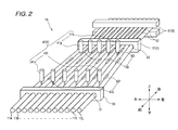
- FIG. 2 the structure of positioning die 3B in the manufacturing apparatus 1A, the mold release agent application part 4, and a connection resin application part is further demonstrated.
- the positioning die 3B is formed with a positioning hole 31 for passing the optical fiber core wires 11A to 11L.
- the positioning holes 31 are formed at predetermined intervals so that a slight gap can be formed between adjacent optical fiber cores of the passed optical fiber cores 11A to 11L.
- the optical fiber cores 11A to 11L which have passed through the positioning die 3B are arranged in parallel on the pass line P with a slight gap between the optical fiber cores.
- the release agent coating unit 4 is composed of 11 release agent application devices 41 (41a to 41k) for applying a release agent between 12 optical fiber cores 11 (11A to 11L).
- 11 release agent application devices 41 41a to 41k for applying a release agent between 12 optical fiber cores 11 (11A to 11L).
- Release agent applying devices 41a to 41f for applying a release agent are disposed on the upstream side (the front side in FIG. 2).
- a release agent is applied to apply a release agent between the optical fiber cores 11B and 11C, 11D and 11E, 11F and 11G, 11H and 11I, and 11J and 11K.
- the coating devices 41g to 41k are disposed downstream (rear side in FIG. 2). For example, an existing mechanism used to intermittently apply the connecting resin may be diverted to the release agent applying devices 41a to 41f.
- the release agent coating devices 41a to 41f intermittently release the release agent 42 (42a to 42f) from the upper side (upper side in FIG. 2) of the surface of the optical fiber between the respective optical fibers at predetermined intervals.
- Apply The release agent coating devices 41g to 41k intermittently apply a release agent 42 (42g to 42k) at predetermined intervals from the surface of the optical fiber between the respective optical fibers.
- the releasing agents 42a to 42f and the releasing agents 42g to 42k are applied side by side in the parallel direction of the optical fiber at the same position in the longitudinal direction of the optical fiber.
- the release agents 42a to 42f are applied such that the positions of the release agents 42a to 42f are between the positions of the release agents 42g to 42k in the longitudinal direction of the optical fiber core wire.
- the release agents 42a to 42k applied from the front surface flow into the back surface side of the optical fiber core wire through the gaps formed between the optical fiber core wires, and are also applied to the back surface side at a predetermined interval.
- the die 5 determines the traveling positions of the optical fiber cores 11A to 11L, and applies the connecting resin 52 around the optical fiber cores 11A to 11L.
- positioning holes 53 for passing the optical fiber cores 11A to 11L are formed.
- the positioning holes 53 are formed at intervals so as not to leave a gap between adjacent optical fiber cores of the passing optical fiber cores 11A to 11L.
- the optical fiber cores 11A to 11L to which the release agents 42a to 42k are applied between the optical fiber cores 11 pass through the die 5, and thus the optical fibers 11A to 11L are arranged in parallel with no gaps between the adjacent optical fiber cores 11. And the connecting resin 52 is applied.
- the portions between the optical fibers 11 are bonded with the connecting resin 52 at the portions where the release agent 42 is not applied, and the portions where the release agent 42 is applied. 11 is not adhered.
- a portion where the optical fiber cores 11 are bonded to each other is a connecting portion where the optical fiber cores 11 are connected.
- a portion where the optical fiber cores are not bonded is a non-connected portion where the optical fiber cores 11 are not connected.
- an ultraviolet curing resin, a thermosetting resin, or the like is used as the connection resin 52.
- the resin curing device 6 is, for example, an ultraviolet irradiation device 61 when the coupling resin 52 is an ultraviolet curing resin, and a heating device when the coupling resin 52 is a thermosetting resin.
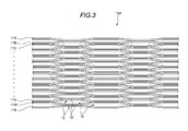
- the intermittent connection type optical fiber ribbon 10A adjacent optical fibers are connected by the connecting resin 52 in a state where 24 optical fibers 11A to 11X are arranged in parallel. It is an intermittent connection type optical fiber tape core in which the connected part 12 and the non-connected part 13 in which adjacent optical fiber cores are not connected are intermittently provided in the longitudinal direction.
- the portion where the release agent 42 is applied by the release agent applying device 41 of the manufacturing apparatus 1A shown in FIG. 2 becomes the non-connecting portion 13 in the intermittent connection type optical fiber ribbon 10A of FIG.
- a portion where the release agent 42 is not applied by the release agent applying device 41 of the manufacturing apparatus 1A shown in FIG. 2 becomes the connecting portion 12 in the intermittent connection type optical fiber ribbon 10A of FIG.
- FIG. 3 shows an intermittently coupled optical fiber ribbon in a state in which the optical fibers 11A to 11X are opened in the arrangement direction.
- optical fiber cores are intermittently connected for each core.
- the manufacturing apparatus 1A can also manufacture an intermittent connection type optical fiber tape core wire intermittently connected for each of two or more cores by changing the number and arrangement of the release agent coating devices 41.
- the optical fibers 11A to 11X shown in FIG. 3 are composed of, for example, a glass fiber composed of a core and a clad, and a covering layer for covering the glass fiber.
- the covering layers of the optical fiber cores 11A to 11X are colored, for example, in different colors so that the optical fiber cores can be distinguished from each other.
- connecting resin when connecting resin is intermittently applied to a plurality of optical fiber cores arranged in parallel, for example, it is necessary to apply a thick connecting resin to some extent in order to obtain good connectivity.
- the release agent 42 is intermittently thinly applied to the surfaces of the plurality of optical fiber cores disposed in parallel.
- the release agent 42 to be applied may have a viscosity lower than that of the connecting resin, since storage properties are not required. Therefore, the manufacturing apparatus 1A that applies the release agent 42 intermittently can increase the linear velocity for traveling the optical fiber at the time of manufacturing, as compared with the apparatus that applies the connection resin intermittently.
- an intermittent pattern can be accurately formed on the optical fiber center line of a state in which a plurality of release agents have lower viscosity than a high viscosity connection resin. Therefore, according to the manufacturing apparatus 1A, the intermittent connection type optical fiber ribbon can be manufactured efficiently and accurately.
- the manufacturing apparatus 1A for example, twelve optical fiber cores 11A to 11L from twelve supply bobbins 21 are caused to travel on the delivery path line P at a predetermined traveling speed.
- the optical fiber cores 11A to 11L are disposed in parallel and passed through the positioning die 3B. By passing the positioning die 3B, the optical fiber cores 11A to 11L are arranged on the pass line P with a slight gap between the adjacent optical fiber cores.
- release agent is supplied from the release agent coating devices 41a to 41f, and between the optical fiber cores 11A and 11B, 11C and 11D, 11E and 11F, and 11G and 11H.
- release agents 42a to 42f are applied at predetermined intervals.
- release agents are supplied from release agents 42g to 42k, and between the optical fiber cores 11B and 11C, 11D and 11E, 11F and 11G, 11H and 11I, 11J And release agents 42g to 42k are applied at predetermined intervals.
- the interval and the amount of application of the release agents 42a to 42k are controlled by the control unit 8.
- the release agents 42a to 42f are applied to the same position in the longitudinal direction of the optical fiber so as to be aligned in the parallel direction of the optical fiber.
- mold release agents 42g to 42k are applied to the same position in the longitudinal direction of the optical fiber so as to be aligned in the parallel direction of the optical fiber.
- the release agents 42a to 42f and the release agents 42g to 42k are arranged such that the positions of the release agents 42a to 42f are disposed between the positions of the release agents 42g to 42k in the longitudinal direction of the optical fiber core wire. Apply intermittently.
- the release agents 42a to 42k supplied from the front surface of the optical fiber core are poured on the back side of the optical fiber core through the gaps formed between the optical fiber cores, and the release agent 42a is also on the back side of the optical fiber core. Apply ⁇ 42k at predetermined intervals.
- connection resin 52 is cured by the resin curing device 6.
- the resin curing device 6 irradiates ultraviolet rays using the ultraviolet irradiation device to cure the connection resin 52.
- the connecting resin 52 adheres to the portions of the optical fiber cores 11A to 11L where the release agent 42 is not applied, and the connecting portion 12 is formed where the optical fiber cores are connected to each other.
- the connection resin 52 is not adhered to the portion where the release agent 42 is applied, and the non-connection portion 13 in which the optical fiber cores are not connected is formed.
- a 12-core intermittent connection type optical fiber ribbon 10 having the connecting portion 12 and the non-connecting portion 13 intermittently is manufactured.
- the linear velocity can be increased more than in the case where the connection resin is intermittently applied for the same reason as in the above manufacturing apparatus 1A, and
- the intermittent pattern can be formed with high accuracy. Therefore, the intermittent connection type optical fiber ribbon can be manufactured efficiently and accurately.
- the manufacturing apparatus 1B (it abbreviates as manufacturing apparatus 1B hereafter) of the optical fiber tape ribbon which concerns on 2nd embodiment of this indication is demonstrated.
- symbol is attached
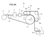
- FIG. 4A is a diagram showing the configuration of the manufacturing apparatus 1B.
- FIG. 4B is a cross-sectional view taken along the line AA of FIG. 4A.
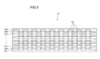
- FIG. 5 is a top view which shows an example of the screen version used when apply
- the manufacturing apparatus 1B uses the screen plate 121 having a pattern in which the holes 123 are intermittently opened as shown in FIG. 5 when applying the release agent to the optical fiber core wire, as described in the first embodiment. Is different from the manufacturing apparatus 1A.
- the manufacturing apparatus 1B includes the supply bobbin portion 2, the guide roller 3A, the release agent applying portion 104, the die 5 and the resin curing device 6 constituting the connected resin applying portion, and the winding bobbin It has nine.
- the speed sensor 7 and the control unit 8 are not shown.
- the release agent application unit 104 includes a drive roll 111 and a guide roll 113 for causing the plurality of optical fiber cores 11A to 11L drawn out from the supply bobbin section 2 to travel on the pass line P, and the optical fibers 11A to 11L.
- a traveling guide belt 112 for guiding the traveling.
- the traveling guide belt 112 is configured to be repeatedly rolled between the drive roll 111 and a guide roll 113 provided on the downstream side of the resin curing device 6.
- the release agent coating unit 104 has a screen plate 121 which is rolled corresponding to the traveling of the optical fiber cores 11A to 11L, and idle rolls 122a to 122c which guide the rolls of the screen plate 121. .
- the screen plate 121 is continuously formed in a belt shape, and is configured to be repeatedly rolled between the three idle rolls 122a to 122c.
- the screen plate 121 is disposed to overlap the optical fibers 11A to 11L, and is rolled in synchronization with the traveling speed of the optical fibers 11A to 11L.
- the release agent application unit 104 has a release agent application device 131 for applying the release agent 42 on the optical fiber cores 11A to 11L on which the screen plate 121 is overlapped.
- the release agent coating device 131 applies the release agent 42 at a time to the screen plate 121 superimposed on the optical fiber cores 11A to 11L.
- the traveling guide belt 112 is formed with positioning grooves 114 for determining the positions of the traveling optical fiber cores 11A to 11L.
- the optical fiber cores 11A to 11L are arranged in the positioning groove 114, and arranged in parallel with adjacent optical fiber cores having a slight gap therebetween.
- channel 115 is formed in the drive roll 111.
- a rib 116 is formed on the back side of the traveling guide belt 112. The rib 116 passes through the groove 115 so that the position of the traveling guide belt 112 in the direction perpendicular to the traveling direction does not shift.
- the screen plate 121 is formed with a number of intermittent pattern rows 124A to 124L corresponding to the number of optical fibers (12 in this example) of the intermittent connection type optical fiber ribbon 10 to be manufactured. It is done.
- the intermittent pattern rows 124A to 124L patterns of holes 123 which are intermittently opened are formed.
- the pattern of the holes 123 is formed, for example, in such a pattern that the holes 123 of adjacent intermittent pattern rows are at mutually offset positions.
- the screen plate 121 is arranged such that the intermittent pattern rows 124A to 124L overlap on the respective optical fiber cores 11A to 11L.
- the screen plate 121 is formed of, for example, a stainless steel rigid material or the like.
- the release agent 42 when the release agent 42 is applied, the release agent 42 may be applied collectively to the screen plate 121.
- a mechanism for intermittently supplying the release agent may be used. There is no need to provide it. Therefore, the linear velocity of the manufacturing apparatus can be further increased. Further, since a desired intermittent pattern can be made in advance by the screen plate 121, it is possible to easily manufacture an intermittent connection type optical fiber tape core of different intermittent patterns only by changing the screen plate 121. Therefore, the intermittent connection type optical fiber ribbon can be manufactured efficiently and accurately.
- the optical fiber cores 11A to 11L drawn out from the supply bobbin unit 2 are disposed in the positioning groove 114 of the traveling guide belt 112 of the release agent applying unit 104 and run. Since the optical fiber cores 11A to 11L are positioned in the positioning groove 114 formed on the traveling guide belt 112, the optical fiber cores are formed with a slight gap between the adjacent optical fiber cores.
- the lines 11A to 11L are arranged in parallel.
- a screen plate 121 is disposed so as to overlap between the cores of the optical fiber cores 11A to 11L arranged side by side with a slight gap, and the mold release agent coating device 131 collectively coats the mold release agent 42 toward the screen plate 121.
- the release agent 42 applied at one time is applied on the inter-cores of the optical fibers 11A to 11L in the pattern of the holes 123 opened in the screen plate 121.
- the mold release agent 42 is applied to the back surface side of the optical fiber core wire with the pattern of the holes 123 of the screen plate 121 by flowing into the back surface side of the optical fiber core wire through the gap opened between the optical fiber cores. Be done.
- the subsequent connecting resin application step of applying the connecting resin 52 is the same as the method of manufacturing an optical fiber ribbon using the manufacturing apparatus 1A of the first embodiment.
- the intermittent connection type optical fiber ribbon can be manufactured efficiently and accurately.
- the manufacturing apparatus and manufacturing method of the optical fiber tape according to the first embodiment and the second embodiment as described above are not limited to the intermittent connection type optical fiber tape 10A of single core intermittent type shown in FIG.
- it is also possible to manufacture an intermittent connection type optical fiber tape core intermittently connected every two or more cores such as a two-core intermittent type intermittent connection type optical fiber tape core 10B shown in FIG.
- an intermittent connection type optical fiber tape core wire intermittently connected every two or more cores is obtained. It can be manufactured. Further, in the second embodiment, by changing the screen plate 121 to a different screen plate, it is possible to manufacture an intermittent connection type optical fiber tape core wire intermittently connected to multicores of two or more cores.
- 1A, 1B Manufacturing apparatus for optical fiber ribbons (manufacturing apparatus) 3B: Positioning die 4, 104: Release agent application unit 5: Die (part of connected resin application unit) 6: Resin curing device (part of connected resin application part) 10, 10A, 10B: Intermittent connection type optical fiber ribbon 11 (11A to 11X): Optical fiber 12: Connection 13: Non connection 42 (42a to 42k): Release agent 52: Connection resin 111: Drive roll 112: Drive guide belt 121: Screen version 122a to 122c: Idle roll
Landscapes
- Physics & Mathematics (AREA)
- General Physics & Mathematics (AREA)
- Optics & Photonics (AREA)
- Engineering & Computer Science (AREA)
- Manufacturing & Machinery (AREA)
- Optical Fibers, Optical Fiber Cores, And Optical Fiber Bundles (AREA)
- Mechanical Coupling Of Light Guides (AREA)
Abstract
Description
本出願は、2018年1月18日出願の日本出願2018-006308号に基づく優先権を主張し、前記日本出願に記載された全ての記載内容を援用するものである。
特許文献2には、内部に空間を有し、外周面に前記空間と連通する複数の塗布孔を有する塗布ロールと、前記空間に配置される加圧部と、前記空間に接着部材を供給する接着部材供給部と、を有する光ファイバテープ心線製造装置が記載されている。そして、前記製造装置を用いて、所定間隔に整列した複数の前記光ファイバ素線の間に対して、接着部材を間欠的に塗布し、前記光ファイバ素線同士を接着する間欠連結型光ファイバテープ心線の製造方法が記載されている。
前記離型剤塗布工程の後に、複数本並列した状態の前記光ファイバを、前記光ファイバの周囲に連結樹脂を塗布するダイスに通過させ、前記連結樹脂を硬化させる連結樹脂塗布工程と、
を有し、
連結部と非連結部とを有する間欠連結型光ファイバテープ心線を製造する。
離型剤が間欠的に塗布された前記複数本の光ファイバを、前記光ファイバの周囲に連結樹脂を塗布するダイスに通過させ、前記連結樹脂を硬化させる連結樹脂塗布部と、
を有し、
連結部と非連結部とを有する間欠連結型光ファイバテープ心線を製造する。
このような間欠連結型光ファイバテープ心線の製造方法において、間欠的に連結樹脂を塗布する際に、例えば特許文献2に記載されている、塗布ロール等の塗布孔から光ファイバ心線間に連結樹脂を塗布すると、一般的に連結樹脂の粘度が高いため、連結樹脂が盛り上がるケースや樹脂溜まりによる塗布異常等が生じるおそれがある。このように、従来の間欠連結型光ファイバテープ心線の製造方法では、光ファイバ心線間に精度良く、連結樹脂を塗布させることが難しい。
本開示の光ファイバテープ心線の製造方法および製造装置によれば、間欠連結型構造の光ファイバテープ心線を、効率良く、精度良く製造することができる。
最初に本開示の実施態様を列記して説明する。
本開示の一態様に係る光ファイバテープ心線の製造方法は、
(1)光ファイバを複数本並列した状態で、光ファイバ間が連結樹脂で接着しないようにするための離型剤を光ファイバの長手方向に間欠的に塗布する離型剤塗布工程と、
前記離型剤塗布工程の後に、複数本並列した状態の前記光ファイバを、前記光ファイバの周囲に連結樹脂を塗布するダイスに通過させ、前記連結樹脂を硬化させる連結樹脂塗布工程と、
を有し、
連結部と非連結部とを有する間欠連結型光ファイバテープ心線を製造する。
連結樹脂を間欠的に塗布する場合は、連結樹脂の粘度をある程度高くする必要があると共に、良好な接続性を得るためある程度厚く塗布する必要がある。これに対して、上記光ファイバテープ心線の製造方法は、離型剤塗布工程で光ファイバの表面に間欠的に薄く離型剤を塗布すればよい。また、離型剤は、連結樹脂よりも粘度が低くてもよい。
したがって、上記光ファイバテープ心線の製造方法は、連結樹脂を間欠的に塗布する場合よりも製造装置の線速を上げることができる。また、連結樹脂よりも離型剤の方が、複数本並列した状態の光ファイバ上に間欠パターンを精度よく形成することができる。
そして、上記離型剤塗布工程の後に、光ファイバの周囲に連結樹脂を塗布するダイスを通過させることで、離型剤が塗布されていない箇所は、光ファイバ間が連結樹脂で接着されて連結部となる。離型剤が塗布されている箇所は、光ファイバ間が連結樹脂で接着されずに非連結部となる。このようにして、連結部と非連結部とを有する間欠連結型光ファイバテープ心線を製造することができる。これにより、間欠連結型構造の光ファイバテープ心線を、効率良く、精度良く製造することができる。
上記方法によれば、光ファイバの表面から、離型剤を間欠的に供給することにより、離型剤を間欠的に塗布することができる。
上記方法によれば、間欠的に離型剤を供給する機構が必要無いので、さらに、製造装置の線速を上げることができる。また、予めスクリーン版により間欠パターンを作っておくことにより、スクリーン版を変えるだけで異なる間欠パターンの間欠連結型光ファイバテープ心線を容易に作ることができる。
(5)前記離型剤は、フッ素化合物をものであってもよい。
(6)前記離型剤は、アルコールを含むものであってもよい。
(7)光ファイバを複数本並列した状態で、光ファイバ間が連結樹脂で接着しないようにするための離型剤を間欠的に塗布する離型剤塗布部と、
離型剤が間欠的に塗布された前記複数本の光ファイバを、前記光ファイバの周囲に連結樹脂を塗布するダイスに通過させ、前記連結樹脂を硬化させる連結樹脂塗布部と、
を有し、
連結部と非連結部とを有する間欠連結型光ファイバテープ心線を製造する。
上記構成によれば、離型剤塗布部によって間欠的に離型剤を塗布するので、連結樹脂を間欠的に塗布する装置よりも、製造時における製造装置の線速を上げることができる。また、連結樹脂よりも離型剤の方が、複数本並列した状態の光ファイバ上に間欠パターンを精度よく形成することができる。
そして、離型剤が間欠的に塗布された、複数本並列した状態の光ファイバを、連結樹脂塗布部の光ファイバの周囲に連結樹脂を塗布するダイスを通過させることで、離型剤が塗布されていない箇所は、光ファイバ間が連結樹脂で接着されて連結部となる。離型剤が塗布されている箇所は、光ファイバ間が連結樹脂で接着されずに非連結部となる。このようにして、連結部と非連結部とを有する間欠連結型光ファイバテープ心線を製造することができる。これにより、間欠連結型構造の光ファイバテープ心線を、効率良く、精度良く製造することができる。
本開示の実施形態に係る光ファイバテープ心線の製造方法および製造装置の具体例を、以下に図面を参照しつつ説明する。
なお、本発明はこれらの例示に限定されるものではなく、請求の範囲によって示され、請求の範囲と均等の意味および範囲内でのすべての変更が含まれることが意図される。
図1は、本開示の第一実施形態に係る光ファイバテープ心線の製造装置1A(以下、製造装置1Aと略記する)を示す。図1に示すように、製造装置1Aは、サプライボビン部2と、ガイドローラ3Aと、位置決めダイス3Bと、離型剤塗布部4と、連結樹脂塗布部を構成するダイス5および樹脂硬化装置6と、速度センサ7と、制御部8と、巻取ボビン9と、を備えている。
光ファイバ心線11A~11Lを並列に配置させて、位置決めダイス3Bを通過させる。位置決めダイス3Bを通過することで、光ファイバ心線11A~11Lは、隣り合う光ファイバ心線間に僅かな隙間が空けられた状態でパスラインP上に配置される。
続いて、光ファイバ心線間に離型剤42a~42kが塗布された光ファイバ心線11A~11Lをダイス51の位置決め孔53に通過させることで、隣り合う光ファイバ心線間に隙間がない状態に並列配置させる。また、その隙間ない状態に並列配置させた光ファイバ心線11A~11Lの周囲に連結樹脂52をダイス5によって一括塗布する。
図4A、図4Bおよび図5を参照して、本開示の第二実施形態に係る光ファイバテープ心線の製造装置1B(以下、製造装置1Bと略記する)について説明する。なお、上記第一実施形態の製造装置1Aと同様の構成については同じ符号を付しその説明を省略する。
(離型剤塗布工程)
サプライボビン部2から繰り出された光ファイバ心線11A~11Lを、離型剤塗布部104の走行ガイドベルト112の位置決め溝114内に配置し、走行させる。走行ガイドベルト112に形成されている位置決め溝114内に光ファイバ心線11A~11Lが位置することで、隣り合う光ファイバ心線同士の間にそれぞれ僅かな隙間を空けられた状態で光ファイバ心線11A~11Lが並列配置される。
3B:位置決めダイス
4,104:離型剤塗布部
5:ダイス(連結樹脂塗布部の一部)
6:樹脂硬化装置(連結樹脂塗布部の一部)
10,10A,10B:間欠連結型光ファイバテープ心線
11(11A~11X):光ファイバ心線
12:連結部
13:非連結部
42(42a~42k):離型剤
52:連結樹脂
111:駆動ロール
112:走行ガイドベルト
121:スクリーン版
122a~122c:アイドルロール
Claims (7)
- 光ファイバを複数本並列した状態で、光ファイバ間が連結樹脂で接着しないようにするための離型剤を光ファイバの長手方向に間欠的に塗布する離型剤塗布工程と、
前記離型剤塗布工程の後に、複数本並列した状態の前記光ファイバを、前記光ファイバの周囲に連結樹脂を塗布するダイスに通過させ、前記連結樹脂を硬化させる連結樹脂塗布工程と、
を有し、
連結部と非連結部とを有する間欠連結型光ファイバテープ心線を製造する、光ファイバテープ心線の製造方法。 - 前記離型剤塗布工程は、前記複数本並列した状態の前記光ファイバの表面から、前記離型剤を間欠的に供給して塗布する工程である、請求項1に記載の光ファイバテープ心線の製造方法。
- 前記離型剤塗布工程は、間欠的に孔が開いたパターンを有するスクリーン版を通して前記離型剤を塗布する工程である、請求項1に記載の光ファイバテープ心線の製造方法。
- 前記離型剤は、シリコーンを含む、請求項1から請求項3のいずれか一項に記載の光ファイバテープ心線の製造方法。
- 前記離型剤は、フッ素化合物を含む、請求項1から請求項3のいずれか一項に記載の光ファイバテープ心線の製造方法。
- 前記離型剤は、アルコールを含む、請求項1から請求項3のいずれか一項に記載の光ファイバテープ心線の製造方法。
- 光ファイバを複数本並列した状態で、光ファイバ間が連結樹脂で接着しないようにするための離型剤を間欠的に塗布する離型剤塗布部と、
離型剤が間欠的に塗布された前記複数本の光ファイバを、前記光ファイバの周囲に連結樹脂を塗布するダイスに通過させ、前記連結樹脂を硬化させる連結樹脂塗布部と、
を有し、
連結部と非連結部とを有する間欠連結型光ファイバテープ心線を製造する、光ファイバテープ心線の製造装置。
Priority Applications (4)
| Application Number | Priority Date | Filing Date | Title |
|---|---|---|---|
| US16/962,612 US11181709B2 (en) | 2018-01-18 | 2019-01-17 | Manufacturing method of optical fiber ribbon and manufacturing apparatus thereof |
| JP2019566492A JP7151728B2 (ja) | 2018-01-18 | 2019-01-17 | 光ファイバテープ心線の製造方法および製造装置 |
| CN201980008867.2A CN111630426B (zh) | 2018-01-18 | 2019-01-17 | 光纤带芯线的制造方法及制造装置 |
| EP19740981.6A EP3742211B1 (en) | 2018-01-18 | 2019-01-17 | Manufacturing method of an optical fiber ribbon |
Applications Claiming Priority (2)
| Application Number | Priority Date | Filing Date | Title |
|---|---|---|---|
| JP2018-006308 | 2018-01-18 | ||
| JP2018006308 | 2018-01-18 |
Publications (1)
| Publication Number | Publication Date |
|---|---|
| WO2019142842A1 true WO2019142842A1 (ja) | 2019-07-25 |
Family
ID=67301417
Family Applications (1)
| Application Number | Title | Priority Date | Filing Date |
|---|---|---|---|
| PCT/JP2019/001174 Ceased WO2019142842A1 (ja) | 2018-01-18 | 2019-01-17 | 光ファイバテープ心線の製造方法および製造装置 |
Country Status (5)
| Country | Link |
|---|---|
| US (1) | US11181709B2 (ja) |
| EP (1) | EP3742211B1 (ja) |
| JP (1) | JP7151728B2 (ja) |
| CN (1) | CN111630426B (ja) |
| WO (1) | WO2019142842A1 (ja) |
Cited By (1)
| Publication number | Priority date | Publication date | Assignee | Title |
|---|---|---|---|---|
| JP2024014493A (ja) * | 2022-07-22 | 2024-02-01 | Swcc株式会社 | 光ファイバテープ心線巻取体の製造方法およびその製造装置 |
Families Citing this family (1)
| Publication number | Priority date | Publication date | Assignee | Title |
|---|---|---|---|---|
| CN113359230B (zh) * | 2021-05-18 | 2022-04-29 | 烽火通信科技股份有限公司 | 一种柔性光纤带及光缆 |
Citations (12)
| Publication number | Priority date | Publication date | Assignee | Title |
|---|---|---|---|---|
| JPS63306407A (ja) * | 1987-06-08 | 1988-12-14 | Mitsubishi Cable Ind Ltd | テ−プ型光ファイバユニット |
| JPH0990179A (ja) * | 1995-07-17 | 1997-04-04 | Furukawa Electric Co Ltd:The | 自己支持型パイプ複合ケーブル |
| JP2000344552A (ja) * | 1999-04-29 | 2000-12-12 | Lucent Technol Inc | 複数のサブユニットに分割可能な光ファイバリボン |
| JP2002341205A (ja) * | 2001-05-14 | 2002-11-27 | Nippon Telegr & Teleph Corp <Ntt> | 光ファイバテープ |
| JP2003177250A (ja) * | 2001-12-13 | 2003-06-27 | Nissha Printing Co Ltd | フロントライト装置用導光板とその製造方法 |
| JP2013088617A (ja) | 2011-10-18 | 2013-05-13 | Fujikura Ltd | 光ファイバテープ心線及びその光ファイバテープ心線を収納した光ファイバケーブル |
| JP2013182146A (ja) * | 2012-03-02 | 2013-09-12 | Furukawa Electric Co Ltd:The | 光ファイバテープ心線の製造方法、光ファイバテープ心線の製造装置、光ファイバテープ心線 |
| JP2014085512A (ja) * | 2012-10-24 | 2014-05-12 | Fujikura Ltd | 光ファイバテープ心線及び光ファイバケーブル |
| JP2016080849A (ja) | 2014-10-16 | 2016-05-16 | 古河電気工業株式会社 | 光ファイバテープ心線の製造方法、光ファイバテープ心線の製造装置 |
| JP2017138594A (ja) * | 2016-02-02 | 2017-08-10 | オーエフエス ファイテル,エルエルシー | 部分結合リボン構造体の高速処理のための方法 |
| JP2017156560A (ja) * | 2016-03-02 | 2017-09-07 | 古河電気工業株式会社 | 光ファイバテープ心線、光ファイバテープ心線の分離方法 |
| JP2018006308A (ja) | 2016-07-07 | 2018-01-11 | 株式会社河端製作所 | 金属板あるいは箔を内蔵した陶磁器あるいはガラス製のih調理器用加熱補助プレート。 |
Family Cites Families (6)
| Publication number | Priority date | Publication date | Assignee | Title |
|---|---|---|---|---|
| US6175677B1 (en) * | 1998-04-17 | 2001-01-16 | Alcatel | Optical fiber multi-ribbon and method for making the same |
| JP4412040B2 (ja) | 2004-04-07 | 2010-02-10 | 日立電線株式会社 | 光ファイバテープユニット及び光ファイバケーブル |
| US7187830B2 (en) * | 2004-12-22 | 2007-03-06 | Corning Cable Systems, Llc. | Optical fiber ribbons having a preferential tear portion formed by curing and methods therefor |
| JP5380396B2 (ja) * | 2010-08-19 | 2014-01-08 | 株式会社フジクラ | 光ファイバテープ心線の検査装置、製造装置及び光ファイバテープ心線の検査方法 |
| JP2012208311A (ja) * | 2011-03-30 | 2012-10-25 | Sumitomo Electric Ind Ltd | 光ファイバテープ心線の製造装置と製造方法 |
| US10989888B2 (en) * | 2016-02-02 | 2021-04-27 | Ofs Fitel, Llc | Flexible ribbon structure and method for making |
-
2019
- 2019-01-17 WO PCT/JP2019/001174 patent/WO2019142842A1/ja not_active Ceased
- 2019-01-17 EP EP19740981.6A patent/EP3742211B1/en active Active
- 2019-01-17 US US16/962,612 patent/US11181709B2/en active Active
- 2019-01-17 JP JP2019566492A patent/JP7151728B2/ja active Active
- 2019-01-17 CN CN201980008867.2A patent/CN111630426B/zh active Active
Patent Citations (12)
| Publication number | Priority date | Publication date | Assignee | Title |
|---|---|---|---|---|
| JPS63306407A (ja) * | 1987-06-08 | 1988-12-14 | Mitsubishi Cable Ind Ltd | テ−プ型光ファイバユニット |
| JPH0990179A (ja) * | 1995-07-17 | 1997-04-04 | Furukawa Electric Co Ltd:The | 自己支持型パイプ複合ケーブル |
| JP2000344552A (ja) * | 1999-04-29 | 2000-12-12 | Lucent Technol Inc | 複数のサブユニットに分割可能な光ファイバリボン |
| JP2002341205A (ja) * | 2001-05-14 | 2002-11-27 | Nippon Telegr & Teleph Corp <Ntt> | 光ファイバテープ |
| JP2003177250A (ja) * | 2001-12-13 | 2003-06-27 | Nissha Printing Co Ltd | フロントライト装置用導光板とその製造方法 |
| JP2013088617A (ja) | 2011-10-18 | 2013-05-13 | Fujikura Ltd | 光ファイバテープ心線及びその光ファイバテープ心線を収納した光ファイバケーブル |
| JP2013182146A (ja) * | 2012-03-02 | 2013-09-12 | Furukawa Electric Co Ltd:The | 光ファイバテープ心線の製造方法、光ファイバテープ心線の製造装置、光ファイバテープ心線 |
| JP2014085512A (ja) * | 2012-10-24 | 2014-05-12 | Fujikura Ltd | 光ファイバテープ心線及び光ファイバケーブル |
| JP2016080849A (ja) | 2014-10-16 | 2016-05-16 | 古河電気工業株式会社 | 光ファイバテープ心線の製造方法、光ファイバテープ心線の製造装置 |
| JP2017138594A (ja) * | 2016-02-02 | 2017-08-10 | オーエフエス ファイテル,エルエルシー | 部分結合リボン構造体の高速処理のための方法 |
| JP2017156560A (ja) * | 2016-03-02 | 2017-09-07 | 古河電気工業株式会社 | 光ファイバテープ心線、光ファイバテープ心線の分離方法 |
| JP2018006308A (ja) | 2016-07-07 | 2018-01-11 | 株式会社河端製作所 | 金属板あるいは箔を内蔵した陶磁器あるいはガラス製のih調理器用加熱補助プレート。 |
Non-Patent Citations (1)
| Title |
|---|
| See also references of EP3742211A4 |
Cited By (2)
| Publication number | Priority date | Publication date | Assignee | Title |
|---|---|---|---|---|
| JP2024014493A (ja) * | 2022-07-22 | 2024-02-01 | Swcc株式会社 | 光ファイバテープ心線巻取体の製造方法およびその製造装置 |
| JP7622010B2 (ja) | 2022-07-22 | 2025-01-27 | Swcc株式会社 | 光ファイバテープ心線巻取体の製造方法およびその製造装置 |
Also Published As
| Publication number | Publication date |
|---|---|
| US20200409006A1 (en) | 2020-12-31 |
| JP7151728B2 (ja) | 2022-10-12 |
| EP3742211A1 (en) | 2020-11-25 |
| JPWO2019142842A1 (ja) | 2021-01-14 |
| CN111630426A (zh) | 2020-09-04 |
| US11181709B2 (en) | 2021-11-23 |
| EP3742211A4 (en) | 2021-09-22 |
| CN111630426B (zh) | 2022-05-06 |
| EP3742211B1 (en) | 2025-12-03 |
Similar Documents
| Publication | Publication Date | Title |
|---|---|---|
| JP6409080B2 (ja) | 部分結合リボン構造体の高速処理のための方法 | |
| RU2759664C1 (ru) | Способ изготовления гибкой волоконно-оптической ленты и лента | |
| TWI725125B (zh) | 間歇連結型光纖帶心線、間歇連結型光纖帶心線之製造方法、光纖纜線及光纖軟線 | |
| JP5789381B2 (ja) | 光ファイバテープ心線の製造方法、製造装置、及びその製造方法で製造された光ファイバテープ心線並びに光ファイバケーブル | |
| JP2012027130A (ja) | 光ファイバテープ心線および光ケーブル | |
| JP2015108756A (ja) | 光ファイバユニット、光ファイバケーブルおよび光ファイバユニットの製造方法 | |
| CN114217397B (zh) | 光纤带的成型方法及专用于实施该成型方法的点胶设备 | |
| WO2019142842A1 (ja) | 光ファイバテープ心線の製造方法および製造装置 | |
| WO2022127141A1 (zh) | 一种光纤带 | |
| US11442238B2 (en) | Optical-fiber ribbon with spaced optical-fiber units | |
| US12386132B2 (en) | Intermittently bonded fiber optic ribbon | |
| JP2012252197A (ja) | 光ファイバテープ心線の製造方法、製造装置、及びその製造方法で製造された光ファイバテープ心線 | |
| JP2019074644A (ja) | 光ファイバテープ心線、ダイス、および、光ファイバテープ心線の製造方法 | |
| JP2012027131A (ja) | 光ファイバテープ心線および光ケーブル | |
| WO2020208816A1 (ja) | 光ファイバテープ心線、ダイス、および、光ファイバテープ心線の製造方法 | |
| JP5864119B2 (ja) | 光ファイバテープ心線の製造方法 | |
| JP7694576B2 (ja) | 光ファイバテープ心線、ダイス、および光ファイバテープ心線の製造方法 | |
| US20250102757A1 (en) | Optical fiber ribbon and production method for producing same | |
| JP6232081B2 (ja) | テープ心線の製造方法及び製造装置、並びに光ファイバ心線の製造方法及び製造装置 | |
| US11860429B2 (en) | Optical-fiber ribbon with spaced optical-fiber units | |
| JP2018035048A (ja) | 線条体の製造方法および線条体の製造装置 | |
| KR20250129973A (ko) | 광케이블용 간헐적 접합 리본 및 제조장치 | |
| JP2015004766A (ja) | 光ファイバケーブル及び光ファイバケーブルの製造方法 | |
| JPS61270705A (ja) | 光学繊維シ−ト状体の連続製造方法 |
Legal Events
| Date | Code | Title | Description |
|---|---|---|---|
| 121 | Ep: the epo has been informed by wipo that ep was designated in this application |
Ref document number: 19740981 Country of ref document: EP Kind code of ref document: A1 |
|
| ENP | Entry into the national phase |
Ref document number: 2019566492 Country of ref document: JP Kind code of ref document: A |
|
| NENP | Non-entry into the national phase |
Ref country code: DE |
|
| ENP | Entry into the national phase |
Ref document number: 2019740981 Country of ref document: EP Effective date: 20200818 |
|
| WWG | Wipo information: grant in national office |
Ref document number: 2019740981 Country of ref document: EP |