WO2019142993A1 - 태양광의 효율적 이용을 위한 태양광 모듈의 설치방법 - Google Patents
태양광의 효율적 이용을 위한 태양광 모듈의 설치방법 Download PDFInfo
- Publication number
- WO2019142993A1 WO2019142993A1 PCT/KR2018/009895 KR2018009895W WO2019142993A1 WO 2019142993 A1 WO2019142993 A1 WO 2019142993A1 KR 2018009895 W KR2018009895 W KR 2018009895W WO 2019142993 A1 WO2019142993 A1 WO 2019142993A1
- Authority
- WO
- WIPO (PCT)
- Prior art keywords
- solar
- projection
- distance
- panel
- reflector
- Prior art date
- Legal status (The legal status is an assumption and is not a legal conclusion. Google has not performed a legal analysis and makes no representation as to the accuracy of the status listed.)
- Ceased
Links
Images


Classifications
-
- H—ELECTRICITY
- H02—GENERATION; CONVERSION OR DISTRIBUTION OF ELECTRIC POWER
- H02S—GENERATION OF ELECTRIC POWER BY CONVERSION OF INFRARED RADIATION, VISIBLE LIGHT OR ULTRAVIOLET LIGHT, e.g. USING PHOTOVOLTAIC [PV] MODULES
- H02S20/00—Supporting structures for PV modules
- H02S20/30—Supporting structures being movable or adjustable, e.g. for angle adjustment
-
- G—PHYSICS
- G06—COMPUTING OR CALCULATING; COUNTING
- G06F—ELECTRIC DIGITAL DATA PROCESSING
- G06F30/00—Computer-aided design [CAD]
- G06F30/10—Geometric CAD
- G06F30/13—Architectural design, e.g. computer-aided architectural design [CAAD] related to design of buildings, bridges, landscapes, production plants or roads
-
- G—PHYSICS
- G06—COMPUTING OR CALCULATING; COUNTING
- G06F—ELECTRIC DIGITAL DATA PROCESSING
- G06F7/00—Methods or arrangements for processing data by operating upon the order or content of the data handled
- G06F7/38—Methods or arrangements for performing computations using exclusively denominational number representation, e.g. using binary, ternary, decimal representation
- G06F7/48—Methods or arrangements for performing computations using exclusively denominational number representation, e.g. using binary, ternary, decimal representation using non-contact-making devices, e.g. tube, solid state device; using unspecified devices
- G06F7/544—Methods or arrangements for performing computations using exclusively denominational number representation, e.g. using binary, ternary, decimal representation using non-contact-making devices, e.g. tube, solid state device; using unspecified devices for evaluating functions by calculation
- G06F7/548—Trigonometric functions; Co-ordinate transformations
-
- H—ELECTRICITY
- H02—GENERATION; CONVERSION OR DISTRIBUTION OF ELECTRIC POWER
- H02S—GENERATION OF ELECTRIC POWER BY CONVERSION OF INFRARED RADIATION, VISIBLE LIGHT OR ULTRAVIOLET LIGHT, e.g. USING PHOTOVOLTAIC [PV] MODULES
- H02S20/00—Supporting structures for PV modules
-
- H—ELECTRICITY
- H02—GENERATION; CONVERSION OR DISTRIBUTION OF ELECTRIC POWER
- H02S—GENERATION OF ELECTRIC POWER BY CONVERSION OF INFRARED RADIATION, VISIBLE LIGHT OR ULTRAVIOLET LIGHT, e.g. USING PHOTOVOLTAIC [PV] MODULES
- H02S40/00—Components or accessories in combination with PV modules, not provided for in groups H02S10/00 - H02S30/00
- H02S40/20—Optical components
- H02S40/22—Light-reflecting or light-concentrating means
-
- H—ELECTRICITY
- H02—GENERATION; CONVERSION OR DISTRIBUTION OF ELECTRIC POWER
- H02S—GENERATION OF ELECTRIC POWER BY CONVERSION OF INFRARED RADIATION, VISIBLE LIGHT OR ULTRAVIOLET LIGHT, e.g. USING PHOTOVOLTAIC [PV] MODULES
- H02S99/00—Subject matter not provided for in other groups of this subclass
-
- Y—GENERAL TAGGING OF NEW TECHNOLOGICAL DEVELOPMENTS; GENERAL TAGGING OF CROSS-SECTIONAL TECHNOLOGIES SPANNING OVER SEVERAL SECTIONS OF THE IPC; TECHNICAL SUBJECTS COVERED BY FORMER USPC CROSS-REFERENCE ART COLLECTIONS [XRACs] AND DIGESTS
- Y02—TECHNOLOGIES OR APPLICATIONS FOR MITIGATION OR ADAPTATION AGAINST CLIMATE CHANGE
- Y02E—REDUCTION OF GREENHOUSE GAS [GHG] EMISSIONS, RELATED TO ENERGY GENERATION, TRANSMISSION OR DISTRIBUTION
- Y02E10/00—Energy generation through renewable energy sources
- Y02E10/50—Photovoltaic [PV] energy
- Y02E10/52—PV systems with concentrators
Definitions
- the present invention relates to solar power generation, and more particularly, to a solar cell module including a solar panel and a solar reflector for reflection of sunlight.
- the term “solar power generation” refers to a method of collecting sunlight incident on plate-like light collecting panels arranged in a longitudinal direction and thereby obtaining electric energy through the solar collecting panels.
- solar power generation refers to a method of collecting sunlight incident on plate-like light collecting panels arranged in a longitudinal direction and thereby obtaining electric energy through the solar collecting panels.
- the importance of alternative energy has been greatly increased due to the depletion of petroleum energy and various kinds of energy or cost increase. For example, a photovoltaic power generation system using solar light is required.
- Such a photovoltaic device includes a photovoltaic module in which solar panels are connected in series and in parallel to receive power normally required, a battery for storing the condensed power, a power regulator for regulating power, and an inverter And the like.
- the solar module includes a solar panel that condenses sunlight and a solar reflector that reflects the sunlight toward the solar panel.
- the sunlight incident on the solar reflector may not be transmitted to the solar panel. That is, there is a problem that the power generation efficiency of the photovoltaic module is not good because the angle of the sunlight reflector coupled with the solar panel is not constant and the angle of engagement is not set so as to satisfy the solar peak altitude.
- a solar module including a solar panel and a solar reflector, the solar panel including a first end of a panel of the solar panel, Determining a tilt angle of the reflector of the solar reflector such that the inclination angle of the reflector of the solar reflector is inclined by a certain angle with the first horizontal imaginary plane including the tangent line when the tangent line along the connection of one end of the reflector plate of the reflector is horizontal;
- a first projection height corresponding to a distance between a first reference point at which a vertical line extending perpendicularly to the first horizontal virtual plane and a distance between the other end of the reflection plate of the solar reflector and a second projection height corresponding to a distance between the other end of the reflection plate, And a second projection height corresponding to a distance between the second reference point and the other end of the reflection plate, the second projection height being reflected from the other end of the reflection plate and being projected onto the first horizontal virtual surface And the first projection distance corresponding to the distance between the distance between the
- the step of determining the inclination angle of the reflector determines an angle corresponding to an altitude of the sun in the middle of the 24 seasons as the inclination angle of the reflector.
- the step of calculating the second projection distance may include calculating the second projection distance using a proportional relationship between the first projection height, the second projection height, the first projection distance, and the second projection distance .
- the calculating the second projection distance calculates the second projection distance in consideration of the fact that the sunlight is projected onto the solar reflector on the basis of the lowest comet having the lowest altitude of the sun in the 24th season do.
- the first projection height is calculated by using a trigonometric function based on the length of the reflector of the solar reflector and the inclination angle of the reflector.
- the first projection distance is calculated using a trigonometric function based on a projection angle of the sunlight at the time of frosting with respect to the first horizontal virtual surface or the second horizontal virtual surface and the first projection height.
- the relationship between the first projection height, the second projection height, the first projection distance, and the second projection distance of the solar light can be determined or the length of the solar panel can be determined so that the sunlight can be transmitted to the solar panel as much as possible irrespective of the change in altitude of the southern part of the sun. .
- FIG. 1 is a reference diagram of an embodiment for explaining the structure of a solar module according to the present invention
- FIG. 2 is a flowchart illustrating an installation method of a solar module for efficient use of solar light according to an embodiment of the present invention.
- FIG. 3 is a reference diagram of an embodiment for explaining the relationship between the solar panel of FIG.
- FIG. 4 is a reference view of an embodiment for explaining the angle relationship according to the combination of the solar panel and the solar reflector shown in FIG. 3;
- FIG. 1 is a reference view of an embodiment for explaining the structure of a solar module 100 according to the present invention.
- the solar module 100 may include a solar panel 110 and a solar reflector 120.
- the solar panel 10 converts the sunlight to which the solar cell is condensed into electric energy.
- the solar panel 110 includes a tempered glass, a solar cell, a back sheet, and the like.
- the tempered glass is incident on the inside of the solar panel, and is installed on the upper outer surface of the solar panel.
- the tempered glass is composed of a piece of low iron.
- a solar cell corresponds to a photovoltaic cell that converts solar energy into electric energy, and can be classified into a silicon solar cell and a compound semiconductor solar cell.
- a solar cell is a thin silicon crystal plate, and a trace amount of phosphorus can be attached on one side thereof.
- the back sheet may be provided as a protective layer under the solar cell.
- the solar reflector 120 is made of a metal material such as mirror aluminum, mirror stainless steel or the like which is excellent in reflectivity and excellent in thermal conductivity.
- the reflector 120 may be coated with a reflective metallic material to improve reflectance.
- the solar reflector 120 may be disposed on one side or both sides of the solar panel 110.
- the solar reflector 120 reflects the incident sunlight to the solar panel 110.
- the solar light reflected by the solar light reflector 120 is incident on the solar light panel 110 in addition to the sunlight itself incident on the solar light panel 110, And performs a function of increasing the light collection efficiency.
- the sunlight reflector 120 is attached to the solar panel 110 by the one end of the panel of the solar panel 110 and the one end of the reflector of the solar light reflector 120 are in contact with each other and the bolt and the nut, Lt; / RTI > Since the incidence angle of the sunlight varies depending on the season or the time of day, the efficiency of the solar power generation may be lowered. Therefore, even if the angle of incident sunlight changes according to the season, It is necessary to determine the coupling angle of the reflector 120 and the solar panel 110 or the length of the solar panel.
- FIG. 2 is a flowchart illustrating an installation method of a solar module for efficient use of solar light according to an embodiment of the present invention.
- a solar module comprising a solar panel and a solar reflector, wherein the first horizontal virtual line including the tangent line when the tangent line along the connection of one end of the panel of the solar panel to the one end of the reflector plate of the solar-
- the inclination angle of the reflection plate of the solar reflector is determined so as to be inclined by a predetermined angle with respect to the plane (Step S200).
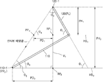
- FIG. 3 is a reference diagram of an embodiment for explaining the relationship between the solar panel 110 shown in FIG. 3 is a reference view illustrating that the sunlight is projected on the sunlight reflector on the basis of the highest altitude and the lowest altitude of the southern peak altitude of the 24th season.
- the angle? 3 can satisfy the following expression (1).
- the first horizontal virtual surface HS 1 is defined as a surface including a tangent line when the tangent line along the connection between the one end of the panel of the solar panel 110 and the one end of the reflector of the solar reflector 120 is horizontal .
- the second horizontal virtual surface HS 2 may be defined as a surface extending horizontally from the other end of the panel of the solar panel 110.
- a first projection height corresponding to a distance between the first reference point at which a vertical line extending perpendicularly to the first horizontal virtual plane and the other end of the reflection plate meet from the other end of the reflection plate of the solar reflector And a second projection height corresponding to a distance between a second reference point that meets a second horizontally extending virtual plane extending from the other end of the panel and a distance between the other end of the reflection plate, And the first projection distance corresponding to the distance between the first projection point at which the sunlight and the first horizontal virtual surface are projected and the first reference point, the sunlight is reflected at the other end of the reflection plate
- FIG. 4 is a reference view of an embodiment for explaining the angle relationship according to the combination of the solar panel 110 and the solar reflector 120 shown in FIG.
- a vertical line (VL) to be referred to as a photovoltaic panel 110, the other end panel (110-1), a second horizontal imaginary plane (HS 2) and that the second reference point (RP 2) extending horizontally from the meeting The distance between the second reference point RP 2 and the other end of the reflector 120-1 may be defined as the second projection height PH 2 .
- the point where the solar light when the sunlight is reflected at the other end 120-1 of the reflector and projected on the first horizontal virtual surface HS 1 and the first horizontal virtual surface HS 1 meet is the first projection point PP 1 ).
- the point sunlight is reflected by the other end reflector 120-1 second horizontal imaginary plane meets the sunlight and the second horizontal imaginary plane (HS 2) of the projection when the (HS 2) of the second projection point ( PP 2 ).
- the distance between the first projection point PP 1 and the first reference point RP 1 defined above is defined as a first projection distance PD 1 and the distance between the second projection point PP 2 and the second reference point RP 2 ) may be defined as a second projection distance PD 2 .
- the second projection distance PD 2 can be calculated.
- the second projection distance (PD 2) considering that the projection in the meridian altitude of the sun most, based on the low-minded photovoltaic solar reflector 120 of the 24 season calculating a second projection distance (PD 2) can do.
- the first projection height PH 1 can be calculated using a trigonometric function based on the reflector length PL of the solar reflector 120 and the reflector tilt angle? 1 .
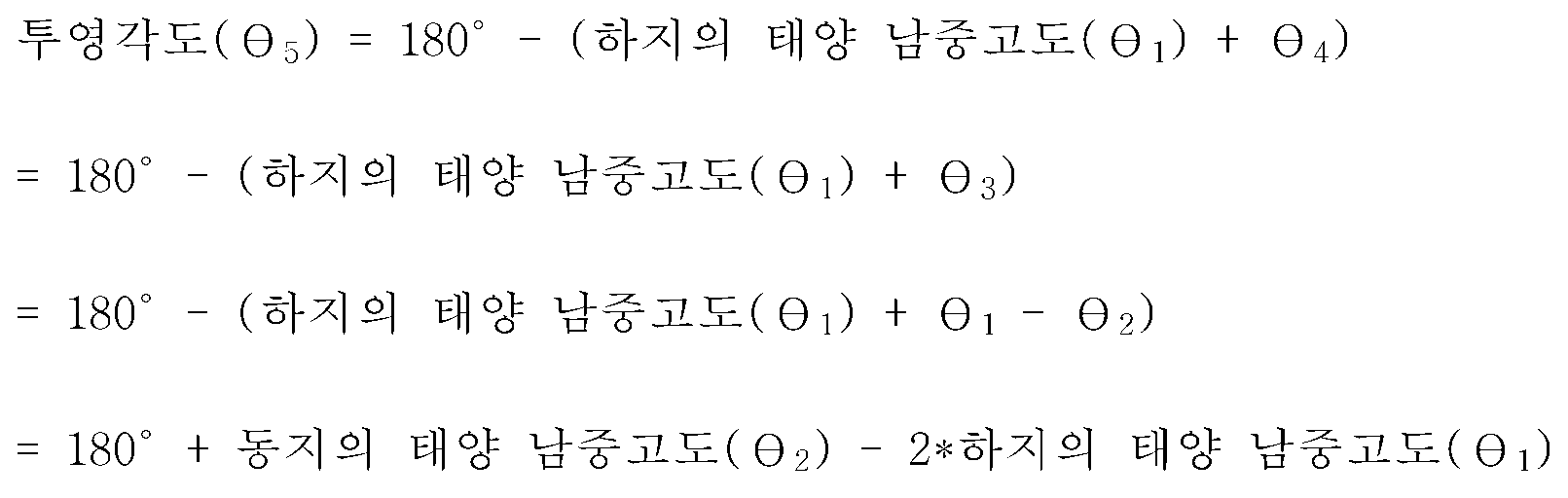
- the first projection distance PD 1 is calculated by using a trigonometric function based on the projection angle 5 and the first projection height PH 1 with respect to the first horizontal virtual surface HS 1 of the sunlight at the time of frost .
- sunlight first horizontal imaginary plane when comrades projection angle with respect to the (HS 1) ( ⁇ 5) is 57 °
- a projection height (PH 1) is as described above L * sin 76 ° of
- the second projection height PH 2 may be a predefined constant value.
- the first projection height PH 1 is L * sin 76 °
- the second projection height PH 2 is a predefined constant value C
- the first projection distance PD 1 is L * sin 76 ° / tan 57 °
- step S202 the panel inclination angle between the solar panel and the second horizontal virtual surface is determined or the length of the solar panel is determined such that the other end of the panel of the solar panel is located at the calculated second projection distance,
- the solar module is installed corresponding to the panel length (step S204).
- the second projection distance a as determined in (PD 2) a step S202, (L * sin 76 ° / tan 57 °) * (C / L * sin 76 °) when the solar panel ( 110 the other end panel (110-1) of the second projection distance) (PD 2), i.e., (L * sin 76 ° / tan 57 °) * solar panel to be positioned at a distance of (C / L * sin 76 ° )
- the length SL of the first and second elastic members 32 and 33 can be determined.
- the solar panel 110 and the solar panel 110 are arranged such that the other end 110-1 of the solar panel 110 is positioned at a distance of (L * sin 76 ° / tan 57 °) * (C / L * sin 76 °) second horizontal imaginary plane may be determined the panel tilt angle ( ⁇ 6) between (HS 2).
- the length SL of the solar panel or the panel tilt angle 6 may be determined independently of each other or may be complementarily determined. For example, when the length SL of the solar panel is relatively short, by reducing the panel inclination angle? 6 , the other end 110-1 of the solar panel 110 is spaced apart from the second projection distance PD 2 By increasing the inclination angle? 6 of the panel when the length SL of the solar panel is relatively long, the other end 110-1 of the solar panel 110 can be determined to be positioned at the second projection It can be determined to be located at the distance PD 2 .
- the length or the inclination angle of the solar panel 110 is adjusted according to the determined panel length or the panel inclination angle.
- a solar reflector is installed. Accordingly, the solar light can be transmitted to the solar panel as much as possible regardless of the altitude of the southern part of the sun, and the solar module 100 can efficiently use the sunlight.
- the present invention can be applied to various playback apparatuses by being implemented in a software program and recorded in a predetermined recording medium readable by a computer.
- the various playback devices may be a PC, a notebook, a portable terminal, and the like.
- the recording medium may be a hard disk, a flash memory, a RAM, a ROM, or the like embedded in each reproduction apparatus, or an external optical disk such as a CD-R or a CD-RW, a compact flash card, a smart media, have.
Landscapes
- Engineering & Computer Science (AREA)
- Physics & Mathematics (AREA)
- General Physics & Mathematics (AREA)
- Theoretical Computer Science (AREA)
- Computational Mathematics (AREA)
- Mathematical Analysis (AREA)
- Mathematical Optimization (AREA)
- Geometry (AREA)
- Pure & Applied Mathematics (AREA)
- Computer Hardware Design (AREA)
- General Engineering & Computer Science (AREA)
- Computing Systems (AREA)
- Civil Engineering (AREA)
- Architecture (AREA)
- Mathematical Physics (AREA)
- Structural Engineering (AREA)
- Evolutionary Computation (AREA)
- Photovoltaic Devices (AREA)
- Optical Elements Other Than Lenses (AREA)
Abstract
Description
Claims (7)
- 태양광 패널 및 태양광 반사판을 포함하는 태양광 모듈에서, 상기 태양광 패널의 패널 일단과 상기 태양광 반사판의 반사판 일단의 연결에 따른 접선이 수평을 이룰 때의 상기 접선을 포함하는 제1 수평 가상면과 일정 각도만큼 경사지도록 상기 태양광 반사판의 반사판 경사각을 결정하는 단계;상기 태양광 반사판의 반사판 타단으로부터 상기 제1 수평 가상면에 수직하게 연장된 수직선이 만나는 제1 기준점과 상기 반사판 타단 사이의 거리에 대응하는 제1 투영높이, 상기 수직선이 상기 태양광 패널의 패널 타단으로부터 수평으로 연장된 제2 수평 가상면과 만나는 제2 기준점과 상기 반사판 타단 사이의 거리에 대응하는 제2 투영높이, 및 상기 태양광이 상기 반사판 타단에서 반사되어 상기 제1 수평 가상면에 투영될 때의 상기 태양광과 상기 제1 수평 가상면이 만나는 제1 투영점과 상기 제1 기준점 사이의 거리에 대응하는 제1 투영거리를 이용하여, 상기 태양광이 상기 반사판 타단에서 반사되어 상기 제2 수평 가상면에 투영될 때의 상기 태양광과 상기 제2 수평 가상면이 만나는 제2 투영점과 상기 제2 기준점 사이의 거리에 대응하는 제2 투영거리를 산출하는 단계; 및상기 태양광 패널의 상기 패널 타단이 상기 산출된 제2 투영거리에 위치하도록 상기 태양광 패널과 상기 제2 수평 가상면 사이의 패널 경사각을 결정하거나 상기 태양광 패널의 길이를 결정하고, 결정된 상기 패널 경사각 또는 상기 패널 길이에 대응하여 상기 태양광 모듈을 설치하는 단계를 포함하는 것을 특징으로 하는 태양광의 효율적 이용을 위한 태양광 모듈의 설치방법.
- 청구항 1에 있어서,상기 반사판 경사각을 결정하는 단계는,24절기 중 하지의 태양 남중 고도에 해당하는 각도를 상기 반사판 경사각으로 결정하는 것을 특징으로 하는 태양광의 효율적 이용을 위한 태양광 모듈의 설치방법.
- 청구항 1에 있어서,상기 제2 투영거리를 산출하는 단계는,상기 제1 투영높이, 상기 제2 투영높이, 상기 제1 투영거리 및 상기 제2 투영거리 사이의 비례 관계를 이용하여 상기 제2 투영거리를 산출하는 것을 특징으로 하는 태양광의 효율적 이용을 위한 태양광 모듈의 설치방법.
- 청구항 1에 있어서,상기 제2 투영거리를 산출하는 단계는,24절기 중 태양의 남중고도가 가장 낮은 동지를 기준으로 상기 태양광이 상기 태양광 반사판에 투영되는 것을 고려하여 상기 제2 투영거리를 산출하는 것을 특징으로 하는 태양광의 효율적 이용을 위한 태양광 모듈의 설치방법.
- 청구항 1에 있어서,상기 제1 투영높이는 상기 태양광 반사판의 반사판 길이와 상기 반사판 경사각에 근거한 삼각함수를 이용하여 산출하는 것을 특징으로 하는 태양광의 효율적 이용을 위한 태양광 모듈의 설치방법.
- 청구항 5에 있어서,상기 제1 투영거리는 동지 때의 상기 태양광의 상기 제1 수평 가상면 또는 상기 제2 수평 가상면에 대한 투영각도와 상기 제1 투영높이에 근거한 삼각함수를 이용하여 산출하는 것을 특징으로 하는 태양광의 효율적 이용을 위한 태양광 모듈의 설치방법.
- 청구항 6에 있어서,상기 투영각도는 다음의 수학식을 이용하여 산출되는 것을 특징으로 하는 태양광의 효율적 이용을 위한 태양광 모듈의 설치방법.[수학식]

Priority Applications (4)
| Application Number | Priority Date | Filing Date | Title |
|---|---|---|---|
| ES18901363T ES3030683T3 (en) | 2018-01-16 | 2018-08-28 | Solar module installation method for efficient use of sunlight |
| US16/960,348 US12057804B2 (en) | 2018-01-16 | 2018-08-28 | Solar module installation method for efficient use of sunlight |
| EP18901363.4A EP3742603B1 (en) | 2018-01-16 | 2018-08-28 | Solar module installation method for efficient use of sunlight |
| JP2020537749A JP7161235B2 (ja) | 2018-01-16 | 2018-08-28 | 太陽光の効率的利用のための太陽光モジュールの設置方法 |
Applications Claiming Priority (2)
| Application Number | Priority Date | Filing Date | Title |
|---|---|---|---|
| KR10-2018-0005599 | 2018-01-16 | ||
| KR1020180005599A KR102004469B1 (ko) | 2018-01-16 | 2018-01-16 | 태양광의 효율적 이용을 위한 태양광 모듈의 설치방법 |
Publications (1)
| Publication Number | Publication Date |
|---|---|
| WO2019142993A1 true WO2019142993A1 (ko) | 2019-07-25 |
Family
ID=67301133
Family Applications (1)
| Application Number | Title | Priority Date | Filing Date |
|---|---|---|---|
| PCT/KR2018/009895 Ceased WO2019142993A1 (ko) | 2018-01-16 | 2018-08-28 | 태양광의 효율적 이용을 위한 태양광 모듈의 설치방법 |
Country Status (6)
| Country | Link |
|---|---|
| US (1) | US12057804B2 (ko) |
| EP (1) | EP3742603B1 (ko) |
| JP (1) | JP7161235B2 (ko) |
| KR (1) | KR102004469B1 (ko) |
| ES (1) | ES3030683T3 (ko) |
| WO (1) | WO2019142993A1 (ko) |
Families Citing this family (3)
| Publication number | Priority date | Publication date | Assignee | Title |
|---|---|---|---|---|
| US20230155543A1 (en) * | 2020-04-07 | 2023-05-18 | Nanovalley Co., Ltd. | Solar cell module including reflection plate and method for adjusting reflection module |
| CN114567248A (zh) * | 2022-02-28 | 2022-05-31 | 阳光新能源开发股份有限公司 | 光伏反光调节方法、系统、终端设备 |
| KR20240131136A (ko) | 2023-02-23 | 2024-08-30 | 동명대학교산학협력단 | 태양광 발전효율 향상을 위한 반사판 장치 |
Citations (5)
| Publication number | Priority date | Publication date | Assignee | Title |
|---|---|---|---|---|
| JPH11330523A (ja) * | 1998-05-13 | 1999-11-30 | Sanyo Electric Co Ltd | 太陽電池装置 |
| JP2002026363A (ja) * | 2000-06-30 | 2002-01-25 | Ntt Power & Building Facilities Inc | 太陽光発電装置 |
| KR101032515B1 (ko) * | 2011-02-23 | 2011-05-04 | 권연희 | 각도조절이 가능한 반사판을 구비한 태양광 발전장치 |
| KR101612426B1 (ko) * | 2014-03-31 | 2016-04-14 | 이재진 | 반사경이 구비된 고정형 태양광 발전기 |
| KR20170034978A (ko) * | 2015-09-21 | 2017-03-30 | (주)운하 | 태양광 발전 장치 |
Family Cites Families (9)
| Publication number | Priority date | Publication date | Assignee | Title |
|---|---|---|---|---|
| JPH08148711A (ja) * | 1994-11-16 | 1996-06-07 | Kyocera Corp | 太陽電池装置 |
| DE69831662T2 (de) * | 1998-07-30 | 2006-07-06 | Hughes Electronics Corp., El Segundo | Spiegelfolien für Konzentrator-Solarpaneele |
| DE102011111473A1 (de) * | 2011-08-23 | 2013-02-28 | Stephan Arens | Verfahren zur Konzentration des Sonnenlichts auf ein Solarmodul mit Hilfe eines Spiegels ohne Neigungsnachführung. |
| ES2659211T3 (es) * | 2014-01-23 | 2018-03-14 | Archimede Research S.R.L. | Planta fotovoltaica |
| KR101570741B1 (ko) * | 2014-04-16 | 2015-11-24 | 이재진 | 반사경이 구비된 고정형 태양광 발전기 |
| CN204906253U (zh) * | 2015-08-14 | 2015-12-23 | 华南农业大学 | 一种追踪反射式集太阳能发电系统 |
| CN205265606U (zh) * | 2015-12-30 | 2016-05-25 | 英利能源(中国)有限公司 | 一种利用光线反射的太阳能光伏组件发电系统 |
| US20170207744A1 (en) * | 2016-01-20 | 2017-07-20 | Pv Innovations | Photovoltaic System with Reflective Panel or Reflective Strip Assembly |
| CN106452335A (zh) * | 2016-10-10 | 2017-02-22 | 同济大学 | 一种光伏发电装置 |
-
2018
- 2018-01-16 KR KR1020180005599A patent/KR102004469B1/ko active Active
- 2018-08-28 US US16/960,348 patent/US12057804B2/en active Active
- 2018-08-28 ES ES18901363T patent/ES3030683T3/es active Active
- 2018-08-28 JP JP2020537749A patent/JP7161235B2/ja active Active
- 2018-08-28 WO PCT/KR2018/009895 patent/WO2019142993A1/ko not_active Ceased
- 2018-08-28 EP EP18901363.4A patent/EP3742603B1/en active Active
Patent Citations (5)
| Publication number | Priority date | Publication date | Assignee | Title |
|---|---|---|---|---|
| JPH11330523A (ja) * | 1998-05-13 | 1999-11-30 | Sanyo Electric Co Ltd | 太陽電池装置 |
| JP2002026363A (ja) * | 2000-06-30 | 2002-01-25 | Ntt Power & Building Facilities Inc | 太陽光発電装置 |
| KR101032515B1 (ko) * | 2011-02-23 | 2011-05-04 | 권연희 | 각도조절이 가능한 반사판을 구비한 태양광 발전장치 |
| KR101612426B1 (ko) * | 2014-03-31 | 2016-04-14 | 이재진 | 반사경이 구비된 고정형 태양광 발전기 |
| KR20170034978A (ko) * | 2015-09-21 | 2017-03-30 | (주)운하 | 태양광 발전 장치 |
Non-Patent Citations (1)
| Title |
|---|
| See also references of EP3742603A4 * |
Also Published As
| Publication number | Publication date |
|---|---|
| KR102004469B1 (ko) | 2019-07-26 |
| EP3742603B1 (en) | 2025-05-21 |
| JP2021513736A (ja) | 2021-05-27 |
| ES3030683T3 (en) | 2025-07-01 |
| KR20190087156A (ko) | 2019-07-24 |
| US12057804B2 (en) | 2024-08-06 |
| EP3742603A1 (en) | 2020-11-25 |
| EP3742603A4 (en) | 2021-06-02 |
| JP7161235B2 (ja) | 2022-10-26 |
| US20200373883A1 (en) | 2020-11-26 |
Similar Documents
| Publication | Publication Date | Title |
|---|---|---|
| US20070240755A1 (en) | Apparatus and method for construction and placement of a non-equatorial photovoltaic module | |
| US6323415B1 (en) | Light concentrator photovoltaic module method of manufacturing same and light concentrator photovoltaic system | |
| WO2019142993A1 (ko) | 태양광의 효율적 이용을 위한 태양광 모듈의 설치방법 | |
| US20110162712A1 (en) | Non-tracked low concentration solar apparatus | |
| CN106371466B (zh) | 一种基于双面电池阵列的太阳能跟踪方法 | |
| CN101345497A (zh) | 一种曲面太阳光接收器 | |
| US6278954B1 (en) | Method and apparatus for estimating generated energy of solar cell | |
| WO2012008659A1 (ko) | 태양 추적장치 및 이를 이용한 태양 추적방법 | |
| KR101146235B1 (ko) | 태양전지 모듈의 발전량 예측 방법 | |
| CN108011574B (zh) | 双面太阳能电池跟踪支架的面板结构设计方法 | |
| JP2005142383A (ja) | 太陽光発電装置 | |
| JP3985837B2 (ja) | 太陽光発電装置及びその設置方法 | |
| JP3794245B2 (ja) | 太陽光発電装置 | |
| WO2008012777A2 (en) | Non-tracking solar collectors | |
| US12341471B2 (en) | Cooling system for solar photovoltac panels | |
| JPH10270740A (ja) | 太陽電池の集光構造体 | |
| HOWELL et al. | Trapezoidal grooves as moderately concentrating solar energy collectors | |
| Yoshioka et al. | Performance evaluation of two-dimensional compound elliptic lens concentrators using a yearly distributed insolation model | |
| JP2005223164A (ja) | 太陽光発電システム及びその設置方法 | |
| KR20210055939A (ko) | 집광 효율이 향상된 건물 일체형 태양광 모듈 | |
| CN201113842Y (zh) | 用于反射式聚光的太阳能接收器 | |
| WO2015160053A1 (ko) | 반사경이 구비된 고정형 태양광 발전기 | |
| CN214900779U (zh) | 一种光伏设备 | |
| WO2024195755A1 (ja) | 太陽電池モジュールの設置構造 | |
| CN209767478U (zh) | 一种光伏发电组件 |
Legal Events
| Date | Code | Title | Description |
|---|---|---|---|
| 121 | Ep: the epo has been informed by wipo that ep was designated in this application |
Ref document number: 18901363 Country of ref document: EP Kind code of ref document: A1 |
|
| ENP | Entry into the national phase |
Ref document number: 2020537749 Country of ref document: JP Kind code of ref document: A |
|
| NENP | Non-entry into the national phase |
Ref country code: DE |
|
| ENP | Entry into the national phase |
Ref document number: 2018901363 Country of ref document: EP Effective date: 20200817 |
|
| WWG | Wipo information: grant in national office |
Ref document number: 2018901363 Country of ref document: EP |