WO2019145991A1 - 内燃機関の制御方法及び内燃機関の制御装置 - Google Patents
内燃機関の制御方法及び内燃機関の制御装置 Download PDFInfo
- Publication number
- WO2019145991A1 WO2019145991A1 PCT/JP2018/001877 JP2018001877W WO2019145991A1 WO 2019145991 A1 WO2019145991 A1 WO 2019145991A1 JP 2018001877 W JP2018001877 W JP 2018001877W WO 2019145991 A1 WO2019145991 A1 WO 2019145991A1
- Authority
- WO
- WIPO (PCT)
- Prior art keywords
- air
- internal combustion
- combustion engine
- intake
- fuel ratio
- Prior art date
- Legal status (The legal status is an assumption and is not a legal conclusion. Google has not performed a legal analysis and makes no representation as to the accuracy of the status listed.)
- Ceased
Links
Images


Classifications
-
- F—MECHANICAL ENGINEERING; LIGHTING; HEATING; WEAPONS; BLASTING
- F02—COMBUSTION ENGINES; HOT-GAS OR COMBUSTION-PRODUCT ENGINE PLANTS
- F02D—CONTROLLING COMBUSTION ENGINES
- F02D41/00—Electrical control of supply of combustible mixture or its constituents
- F02D41/0002—Controlling intake air
- F02D41/0007—Controlling intake air for control of turbo-charged or super-charged engines
-
- F—MECHANICAL ENGINEERING; LIGHTING; HEATING; WEAPONS; BLASTING
- F02—COMBUSTION ENGINES; HOT-GAS OR COMBUSTION-PRODUCT ENGINE PLANTS
- F02D—CONTROLLING COMBUSTION ENGINES
- F02D13/00—Controlling the engine output power by varying inlet or exhaust valve operating characteristics, e.g. timing
- F02D13/02—Controlling the engine output power by varying inlet or exhaust valve operating characteristics, e.g. timing during engine operation
- F02D13/0223—Variable control of the intake valves only
- F02D13/0234—Variable control of the intake valves only changing the valve timing only
-
- F—MECHANICAL ENGINEERING; LIGHTING; HEATING; WEAPONS; BLASTING
- F02—COMBUSTION ENGINES; HOT-GAS OR COMBUSTION-PRODUCT ENGINE PLANTS
- F02D—CONTROLLING COMBUSTION ENGINES
- F02D41/00—Electrical control of supply of combustible mixture or its constituents
- F02D41/02—Circuit arrangements for generating control signals
- F02D41/14—Introducing closed-loop corrections
- F02D41/1438—Introducing closed-loop corrections using means for determining characteristics of the combustion gases; Sensors therefor
- F02D41/1444—Introducing closed-loop corrections using means for determining characteristics of the combustion gases; Sensors therefor characterised by the characteristics of the combustion gases
- F02D41/1454—Introducing closed-loop corrections using means for determining characteristics of the combustion gases; Sensors therefor characterised by the characteristics of the combustion gases the characteristics being an oxygen content or concentration or the air-fuel ratio
-
- F—MECHANICAL ENGINEERING; LIGHTING; HEATING; WEAPONS; BLASTING
- F02—COMBUSTION ENGINES; HOT-GAS OR COMBUSTION-PRODUCT ENGINE PLANTS
- F02D—CONTROLLING COMBUSTION ENGINES
- F02D41/00—Electrical control of supply of combustible mixture or its constituents
- F02D41/30—Controlling fuel injection
- F02D41/3011—Controlling fuel injection according to or using specific or several modes of combustion
- F02D41/3017—Controlling fuel injection according to or using specific or several modes of combustion characterised by the mode(s) being used
- F02D41/3023—Controlling fuel injection according to or using specific or several modes of combustion characterised by the mode(s) being used a mode being the stratified charge spark-ignited mode
- F02D41/3029—Controlling fuel injection according to or using specific or several modes of combustion characterised by the mode(s) being used a mode being the stratified charge spark-ignited mode further comprising a homogeneous charge spark-ignited mode
-
- F—MECHANICAL ENGINEERING; LIGHTING; HEATING; WEAPONS; BLASTING
- F02—COMBUSTION ENGINES; HOT-GAS OR COMBUSTION-PRODUCT ENGINE PLANTS
- F02D—CONTROLLING COMBUSTION ENGINES
- F02D41/00—Electrical control of supply of combustible mixture or its constituents
- F02D41/30—Controlling fuel injection
- F02D41/3011—Controlling fuel injection according to or using specific or several modes of combustion
- F02D41/3064—Controlling fuel injection according to or using specific or several modes of combustion with special control during transition between modes
- F02D41/307—Controlling fuel injection according to or using specific or several modes of combustion with special control during transition between modes to avoid torque shocks
-
- F—MECHANICAL ENGINEERING; LIGHTING; HEATING; WEAPONS; BLASTING
- F02—COMBUSTION ENGINES; HOT-GAS OR COMBUSTION-PRODUCT ENGINE PLANTS
- F02D—CONTROLLING COMBUSTION ENGINES
- F02D41/00—Electrical control of supply of combustible mixture or its constituents
- F02D41/0002—Controlling intake air
- F02D2041/002—Controlling intake air by simultaneous control of throttle and variable valve actuation
-
- F—MECHANICAL ENGINEERING; LIGHTING; HEATING; WEAPONS; BLASTING
- F02—COMBUSTION ENGINES; HOT-GAS OR COMBUSTION-PRODUCT ENGINE PLANTS
- F02D—CONTROLLING COMBUSTION ENGINES
- F02D2200/00—Input parameters for engine control
- F02D2200/02—Input parameters for engine control the parameters being related to the engine
- F02D2200/10—Parameters related to the engine output, e.g. engine torque or engine speed
- F02D2200/101—Engine speed
Definitions
- the present invention relates to a control method of an internal combustion engine and a control device of the internal combustion engine.
- Patent Document 1 discloses a technology for eliminating the torque shock when the combustion mode is switched from stratified combustion with a lean air-fuel ratio to homogeneous combustion with a rich air-fuel ratio as the operating state of the internal combustion engine changes.
- the throttle valve is closed by a predetermined amount before the fuel injection mode is switched from fuel injection for achieving stratified combustion to fuel injection for achieving homogeneous combustion. Then, in order to cancel the sharp increase in engine torque when the air-fuel ratio changes from stratified combustion with lean air-fuel ratio to homogeneous combustion with rich air-fuel ratio, retard of the ignition timing and increase correction of the fuel injection amount are implemented. There is. Retardation of the ignition timing is performed when switching the fuel injection mode.
- the increase correction of the fuel injection amount estimates the amount of air remaining in each cylinder in which the fuel injection mode is switched, and is performed only for the first one combustion cycle of each cylinder after the fuel injection mode is switched.
- this patent document 1 does not cancel out a sharp increase in engine torque when the air-fuel ratio changes from an operation state in which the air-fuel ratio is lean in a supercharged state to an operation state in which the air-fuel ratio is rich in a non-supercharged state.
- Patent Document 1 does not consider the response delay of the intake pressure when the air-fuel ratio changes from an operation state in which the air-fuel ratio is lean in a supercharged state to an operation state in which the air-fuel ratio is rich in a non-supercharged state.
- the intake pressure may be higher than the exhaust pressure due to the response delay of the intake pressure. is there.
- pump work may occur due to an increase in the amount of intake air at the time of transition, and an unintentional torque overshoot may occur.
- the internal combustion engine according to the present invention is a second operating state in which the air-fuel ratio becomes a predetermined lean air-fuel ratio in a supercharged state to a predetermined rich air-fuel ratio that is richer than the lean air-fuel ratio in a non-supercharged state.
- the amount of air in the cylinder is reduced more than the amount of air for achieving the rich air-fuel ratio, and the amount of air in the cylinder is controlled so that the torque overshoot due to the work of the internal combustion engine does not occur.
- the combustion torque of the internal combustion engine can be suppressed by reducing the amount of air in the cylinder, and torque overshoot can be suppressed.
- Explanatory drawing which shows the outline of the control apparatus of the internal combustion engine which concerns on this invention.
- Explanatory drawing which shows the outline of the map used for calculation of an air fuel ratio.
- the timing chart which shows the mode of a change of various parameters at the time of transition of a comparative example.
- 5 is a timing chart showing how various parameters change during a transition of the first embodiment of the present invention.
- Explanatory drawing which shows the outline of the map used for calculation of predetermined amount (DELTA) P.
- 3 is a flowchart showing the flow of control of the internal combustion engine in the first embodiment.
- the timing chart which shows the mode of a change of various parameters at the time of transition of a comparative example.
- the timing chart which shows the mode of a change of various parameters at the time of transition of a 2nd example of the present invention.
- Explanatory drawing which shows the outline of the map used for calculation of predetermined amount (DELTA) Q.
- the flowchart which shows the flow of control of the internal combustion engine in 2nd Example.
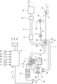
- FIG. 1 is an explanatory view showing an outline of a control device of the internal combustion engine 1.
- the internal combustion engine 1 is, for example, a spark ignition type gasoline engine, mounted on a vehicle such as a car as a drive source, and has an intake passage 2 and an exhaust passage 3.
- the intake passage 2 is connected to the combustion chamber 6 via an intake valve 4.
- the exhaust passage 3 is connected to the combustion chamber 6 via an exhaust valve 5.
- the internal combustion engine 1 has, for example, an in-cylinder direct injection type configuration, and a fuel injection valve (not shown) for injecting fuel into a cylinder and an ignition plug 7 are provided for each cylinder.
- the injection timing and injection amount of the fuel injection valve and the ignition timing of the spark plug 7 are controlled by a control signal from the control unit 8.
- the internal combustion engine 1 has, as a valve operating mechanism of the intake valve 4, an intake-side variable valve mechanism 10 capable of changing the valve timing (opening and closing timing) of the intake valve 4.
- the valve operating mechanism on the exhaust valve side is a general direct acting valve operating mechanism, and the lift operating angle of the exhaust valve 5 and the phase of the lift central angle are always constant.
- the intake-side variable valve mechanism 10 is hydraulically driven, for example, and is controlled by a control signal from the control unit 8. That is, the control unit 8 corresponds to a control unit that controls the intake-side variable valve mechanism 10.
- the control unit 8 can variably control the valve timing of the intake valve 4.
- the intake-side variable valve mechanism 10 can control the amount of air in the cylinder by controlling the closing timing of the intake valve 4. For example, when the intake valve closing timing is retarded than the bottom dead center, the air amount in the cylinder is reduced by retarding the intake valve closing timing so as to be farther than the bottom dead center. Can.
- the intake-side variable valve mechanism 10 corresponds to an air amount control unit capable of variably controlling the air amount in the cylinder.
- the intake-side variable valve mechanism 10 may be of a type in which the opening timing and closing timing of the intake valve 4 can be independently changed independently, or may be of a type in which the opening timing and closing timing are simultaneously delayed. In this embodiment, the latter type is used in which the phase of the intake camshaft 11 relative to the crankshaft 12 is retarded. Further, the intake-side variable valve mechanism 10 is not limited to one driven hydraulically, and may be electrically driven by a motor or the like.
- the valve timing of the intake valve 4 is detected by the intake side camshaft position sensor 13.
- the intake side camshaft position sensor 13 detects the phase of the intake side camshaft 11 with respect to the crankshaft 12.
- the intake passage 2 is provided with an air cleaner 16 for collecting foreign matters in intake, an air flow meter 17 for detecting the amount of intake air, and an electric throttle valve 18 capable of controlling the amount of intake air in the cylinder. There is.
- the air flow meter 17 incorporates a temperature sensor, and can detect (measure) the intake temperature of the intake port.
- the air flow meter 17 is disposed downstream of the air cleaner 16.
- the throttle valve 18 is provided with an actuator such as an electric motor, and the degree of opening thereof is controlled by a control signal from the control unit 8.
- the throttle valve 18 is disposed downstream of the air flow meter 17.
- the opening degree (throttle opening degree) of the throttle valve 18 is detected by a throttle opening degree sensor 19.
- a detection signal of the throttle opening degree sensor 19 is input to the control unit 8.
- the exhaust passage 3 is provided with an upstream exhaust catalyst 21 such as a three-way catalyst, a downstream exhaust catalyst 22 such as a three-way catalyst, and a muffler 23 for noise reduction that reduces exhaust noise.
- the downstream side exhaust catalyst 22 is disposed downstream of the upstream side exhaust catalyst 21.
- the muffler 23 is disposed downstream of the downstream side exhaust catalyst 22.
- the internal combustion engine 1 has a turbocharger 25 as a turbocharger provided coaxially with a compressor 26 provided in the intake passage 2 and a turbine 27 provided in the exhaust passage 3.
- the compressor 26 is disposed upstream of the throttle valve 18 and downstream of the air flow meter 17.
- the turbine 27 is disposed upstream of the upstream exhaust catalyst 21.
- An intake bypass passage 30 is connected to the intake passage 2.
- the intake bypass passage 30 is formed to bypass the compressor 26 and communicate the upstream side and the downstream side of the compressor 26.
- An electric recirculation valve 31 is provided in the intake bypass passage 30.
- the recirculation valve 31 is normally closed, but is opened when, for example, the throttle valve 18 is closed and the downstream side of the compressor 26 has a high pressure.
- Opening and closing of the recirculation valve 31 is controlled by a control signal from the control unit 8.
- the recirculation valve 31 is not controlled by the control unit 8 and may be a so-called check valve which opens only when the pressure on the downstream side of the compressor 26 reaches a predetermined pressure or more. It is possible.
- an intercooler 32 is provided downstream of the throttle valve 18 in the intake passage 2 for cooling the intake air compressed (pressed) by the compressor 26 to improve volumetric efficiency.
- the intercooler 32 is disposed in the intercooler cooling path (sub cooling path) 35 together with the intercooler radiator (intercooler radiator) 33 and the electric pump 34.
- the intercooler 32 can be supplied with the refrigerant (cooling water) cooled by the radiator 33.
- the intercooler cooling path 35 is configured such that the refrigerant can circulate in the path.
- the intercooler cooling path 35 is a cooling path independent of a main cooling path (not shown) in which cooling water for cooling the cylinder block 37 of the internal combustion engine 1 circulates.
- the radiator 33 cools the refrigerant in the intercooler cooling path 35 by heat exchange with the outside air.
- the electric pump 34 circulates the refrigerant in the intercooler cooling path 35 in the arrow A direction by being driven.
- the exhaust passage 3 is connected to an exhaust bypass passage 38 which bypasses the turbine 27 and connects the upstream side and the downstream side of the turbine 27.
- the downstream end of the exhaust bypass passage 38 is connected to the exhaust passage 3 at a position upstream of the upstream exhaust catalyst 21.
- a motorized waste gate valve 39 for controlling the exhaust flow rate in the exhaust bypass passage 38 is disposed.
- the internal combustion engine 1 can carry out exhaust gas recirculation (EGR) for introducing (recirculating) a part of the exhaust gas from the exhaust gas passage 3 into the intake gas passage 2 as EGR gas.
- EGR exhaust gas recirculation
- An EGR passage 41 connected to the passage 2 is provided. One end of the EGR passage 41 is connected to the exhaust passage 3 at a position between the upstream side exhaust catalyst 21 and the downstream side exhaust catalyst 22, and the other end is the downstream side of the air flow meter 17 and the upstream side of the compressor 26 Are connected to the intake passage 2.
- the EGR passage 41 is provided with an electrically operated EGR valve 42 for controlling the flow rate of the EGR gas in the EGR passage 41 and an EGR cooler 43 capable of cooling the EGR gas.
- the opening and closing operation of the EGR valve 42 is controlled by a control unit 8 as a control unit.
- the control unit 8 includes a crank angle sensor 45 capable of detecting the engine rotational speed as well as the crank angle of the crankshaft 12 in addition to the detection signals of the intake side camshaft position sensor 13, the air flow meter 17 and the throttle opening degree sensor 19 described above Detection signals from sensors such as an accelerator opening sensor 46 for detecting the depression amount of an accelerator pedal (not shown), a supercharging pressure sensor 47 for detecting supercharging pressure, and an exhaust pressure sensor 48 for detecting exhaust pressure are input. ing.
- the supercharging pressure sensor 47 is disposed in the intake passage 2 downstream of the intercooler 32, for example, a collector, and detects an intake pressure at the position.
- the exhaust pressure sensor 48 is disposed in the exhaust passage 3 upstream of the turbine 27 and detects the exhaust pressure at that position.
- the control unit 8 calculates the required load (engine load) of the internal combustion engine 1 using the detection value of the accelerator opening sensor 46.
- the control unit 8 controls the ignition timing and air-fuel ratio of the internal combustion engine 1 and controls the opening degree of the EGR valve 42 to control one of the exhaust from the exhaust passage 3 to the intake passage 2.
- the exhaust gas recirculation control (EGR control) etc. which reflux the part is implemented.
- the control unit 8 also controls the drive of the electric pump 34, the opening degree of the throttle valve 18 and the waste gate valve 39, and the like.
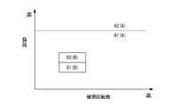
- the control unit 8 controls the air-fuel ratio of the internal combustion engine 1 according to the operating condition, using the air-fuel ratio calculation map shown in FIG. FIG. 2 is an air-fuel ratio calculation map stored in the control unit 8.
- the air-fuel ratio is allocated according to the engine load and the engine speed.
- the control unit 8 controls the air-fuel ratio to be the stoichiometric air-fuel ratio in a predetermined first operation area A, and is leaner than the first operation area A in a predetermined second operation area B on the low rotation low load side. Control is performed to achieve the air-fuel ratio. That is, the air-fuel ratio of the first operating range A corresponds to a predetermined rich air-fuel ratio, and the air-fuel ratio of the second operating range B corresponds to a predetermined lean air-fuel ratio.
- the low load side area A1 of the first operation area A is a non-supercharged area where the turbocharger 25 does not perform supercharging.
- An area A2 on the high load side of the first operation area A is a supercharging area where the turbocharger 25 performs supercharging.
- the area A1 corresponds to a second operating state in which the air-fuel ratio is richer than the air-fuel ratio in the second operating area B in the non-supercharged state.
- the low load side area B1 of the second operation area B is a non-supercharged area in which the turbocharger 25 does not perform supercharging.
- An area B2 on the high load side of the second operation area B is a supercharging area where the turbocharger 25 performs supercharging.
- the region B2 corresponds to a first operating state in which the air-fuel ratio becomes a predetermined lean air-fuel ratio in the supercharging state.
- the air-fuel ratio changes so as to be relatively rich, so the amount of air in the cylinder is controlled to decrease.
- the opening degree (throttle opening degree) of the throttle valve 18 is moved to the valve closing side so as to become the target throttle opening degree at steady state of the region A1. Fully open. However, in this case, since the supercharging pressure in the region B2 remains, the responsiveness of the exhaust pressure drop due to full opening of the waste gate valve 39 can be obtained by moving the throttle valve 18 in the valve closing direction. The responsiveness of the decrease in intake pressure may be delayed, and the intake pressure may be higher than the exhaust pressure.
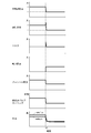
- FIG. 3 is a timing chart showing changes in various parameters at the transition time of transition of the operating state from the area B2 to the area A1 in the comparative example.
- the operating state is changed from the region B2 in which the air-fuel ratio becomes lean in the supercharged state to the region A1 in which the air-fuel ratio becomes richer than this lean air-fuel ratio in the non-supercharged state.
- the opening degree of the throttle valve 18 (throttle opening degree) is set to a predetermined amount than the target throttle opening degree at steady state of area A1 so that the intake pressure becomes lower than the exhaust pressure.
- control is performed so that the target throttle opening degree in the steady state of the region A1 is obtained.
- the amount of air in the cylinder is reduced so that the overshoot of the internal combustion engine 1 torque does not occur at the transition time when the operating state changes from area B2 to area A1.
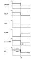
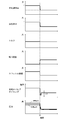
- FIG. 4 is a timing chart showing changes in various parameters at the transition time when the operating state transitions from the area B2 to the area A1 in the first embodiment.
- Closing the throttle valve 18 causes a pressure loss, which allows the intake pressure to be lower than the exhaust pressure.
- the throttle opening is closed by a predetermined amount ⁇ P smaller than the target throttle opening at steady state in region A1 to ensure intake pressure. It can be lower than the exhaust pressure.
- FIG. 5 schematically shows a calculation map of the predetermined amount ⁇ P to which the predetermined amount ⁇ P is allocated.
- the predetermined amount ⁇ P calculation map is stored in the control unit 8.
- the predetermined amount ⁇ P is set larger as the boost pressure in the region B2 is higher, and set smaller as the engine speed of the internal combustion engine in the region B2 is higher.
- the intake pressure can be sufficiently reduced, and the occurrence of the pump work can be more reliably suppressed.
- the curve rising to the right in FIG. 5 shows the relationship between the predetermined amount ⁇ P and the supercharging pressure in the region B2 when the engine rotational speeds Ne1 to Ne4 (Ne1 ⁇ Ne2 ⁇ Ne3 ⁇ Ne4) are used as parameters.
- the predetermined amount ⁇ P is set smaller as the engine speed of the internal combustion engine in the region B2 is higher.
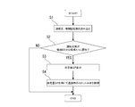
- FIG. 6 is a flow chart showing the flow of control of the internal combustion engine 1 in the first embodiment described above.
- step S1 the supercharging pressure and the engine speed are read.
- step S2 it is determined whether the driving state has transitioned from area B2 to area A1. If it is determined in step S2 that the driving state has transitioned from area B2 to area A1, the process proceeds to step S3. If it is not determined in step S2 that the driving state has transitioned from the region B2 to the region A1, the current routine is ended.
- step S3 a predetermined amount ⁇ P is calculated using the supercharging pressure and the engine speed.
- step S4 the target throttle opening degree at the transition time when the operating state transitions from the region B2 to the region A1 is corrected using the predetermined amount ⁇ P. That is, at the beginning of a transition when the operating state transitions from region B2 to region A1, throttle valve 18 is temporarily controlled to be smaller by a predetermined amount ⁇ P than the target throttle opening degree at steady state of region A1. Ru.
- the predetermined amount ⁇ P is determined according to the supercharging pressure and the engine speed, but the predetermined amount ⁇ P is calculated using only the supercharging pressure or the engine speed. You may do so.
- the amount of air in the cylinder is smaller than the amount of air for achieving a rich air-fuel ratio at the transition time when the operating state changes from region B2 to region A1.
- the air amount control unit in the second embodiment is not the throttle valve 18 but the intake-side variable valve mechanism 10.
- the closing timing of the intake valve 4 is moved so as to be the target intake valve closing timing at steady state of the region A1, and the opening degree of the throttle valve 18 (throttle opening degree) Is moved to the valve closing side so that the target throttle opening degree in the steady state of the region A1 is obtained, and the waste gate valve 39 is fully opened.
- FIG. 7 is a timing chart showing changes in various parameters during transition when the operating state transitions from area B2 to area A1 in the comparative example.
- the responsiveness of the exhaust pressure drop due to full opening of the waste gate valve 39 can be obtained by moving the throttle valve 18 in the valve closing direction.
- the responsiveness of the decrease in intake pressure may be delayed, and the intake pressure may be higher than the exhaust pressure.
- the intake valve closing timing in FIG. 7 is an example in which the target intake valve closing timing in steady state is after the intake bottom dead center in both the area A1 and the area B2.
- the operating state transitions from the region B2 in which the air-fuel ratio becomes lean in the supercharged state to the region A1 in which the air-fuel ratio becomes richer than this lean air-fuel ratio in the non-supercharged state.
- the intake valve closing timing is controlled so as to be temporarily away from the bottom dead center by a predetermined amount ⁇ Q further than the intake valve closing timing in steady state of region A1, steady state in region A1 Control is performed so that the intake valve closing timing is reached.
- the intake-side variable valve mechanism 10 moves away from the bottom dead center more than the target intake valve closing time at steady state in area A1.
- the valve timing of the intake valve 4 is temporarily advanced or retarded.
- FIG. 8 is a timing chart showing changes in various parameters at the transition time when the operating state transitions from area B2 to area A1 in the second embodiment.
- the intake-side variable valve mechanism 10 operates during transition when the operating state transitions from the region B2 to the region A1.
- the valve timing of the intake valve 4 is controlled so that the intake valve closing timing temporarily advances further than the target intake valve closing timing at the steady state of the region A1.
- the amount of air in the cylinder is reduced so that the torque overshoot does not occur in the internal combustion engine 1 at the transition time when the operating state changes from the region B2 to the region A1.
- the intake valve closing timing in FIG. 8 is an example in which the target intake valve closing timing in the steady state is after the intake bottom dead center in both the area A1 and the area B2.
- the intake valve closing timing is controlled so as to temporarily move away from the bottom dead center by a predetermined amount ⁇ Q further than the intake valve closing timing at steady state in region A1.
- FIG. 9 schematically shows a calculation map of the predetermined amount ⁇ Q to which the predetermined amount ⁇ Q is allocated.
- the predetermined amount ⁇ Q calculation map is stored in the control unit 8.
- the predetermined amount ⁇ Q is set larger as the supercharging pressure in the region B2 is higher, and set smaller as the engine speed of the internal combustion engine in the region B2 is higher.
- the curve rising to the right in FIG. 9 shows the relationship between the predetermined amount ⁇ Q and the supercharging pressure in the region B2 when the engine rotational speeds Ne1 to Ne4 (Ne1 ⁇ Ne2 ⁇ Ne3 ⁇ Ne4) are used as parameters.
- the intake pressure can be sufficiently reduced, and the occurrence of the pump work can be more reliably suppressed.
- the predetermined amount ⁇ Q can be set smaller as the engine speed of the internal combustion engine in the region B2 becomes higher.
- FIG. 10 is a flowchart showing the flow of control of the internal combustion engine 1 in the second embodiment described above.
- step S11 the supercharging pressure and the engine speed are read.
- step S12 it is determined whether the driving state has transitioned from area B2 to area A1. If it is determined in step S12 that the driving state has transitioned from area B2 to area A1, the process proceeds to step S13. If it is not determined in step S12 that the driving state has transitioned from the area B2 to the area A1, the current routine is ended.
- step S13 a predetermined amount ⁇ Q is calculated using the supercharging pressure and the engine speed.
- step S14 the intake-side variable valve mechanism 10 is controlled at the transition time when the operating state transitions from the region B2 to the region A1 using the predetermined amount ⁇ Q. That is, at the beginning of the transition when the operating state transitions from region B2 to region A1, the intake variable valve mechanism 10 temporarily reduces the intake valve closing timing to a point lower than the intake valve closing timing at the steady state of the region A1. Control is performed so as to move away from the intake bottom dead center by a fixed amount ⁇ Q.
- the predetermined amount ⁇ Q is determined according to the supercharging pressure and the engine speed, but the predetermined amount ⁇ Q is calculated using only the supercharging pressure or the engine speed. You may do so.
- each embodiment mentioned above relates to the control method and control device of the internal combustion engine 1.
Landscapes
- Engineering & Computer Science (AREA)
- Chemical & Material Sciences (AREA)
- Combustion & Propulsion (AREA)
- Mechanical Engineering (AREA)
- General Engineering & Computer Science (AREA)
- Output Control And Ontrol Of Special Type Engine (AREA)
- Electrical Control Of Air Or Fuel Supplied To Internal-Combustion Engine (AREA)
- Control Of Throttle Valves Provided In The Intake System Or In The Exhaust System (AREA)
- Combined Controls Of Internal Combustion Engines (AREA)
Abstract
過渡時にスロットル弁の開度(スロットル開度)を領域A1の定常時の目標スロットル開度よりも所定量ΔPさらに閉弁側に一時的に動かした後、領域A1の定常時の目標スロットル開度となるように制御する。上記過渡時は、過給状態で空燃比が所定のリーン空燃比となる領域B2から、非過給状態でこのリーン空燃比よりもリッチな所定のリッチ空燃比となる領域A1に運転状態が遷移する過渡時とする。これによって、過渡時においては、筒内の空気量を減少させることで内燃機関の燃焼トルクを抑制し、トルクのオーバーシュートを抑制できる。
Description
本発明は、内燃機関の制御方法及び内燃機関の制御装置に関する。
特許文献1には、内燃機関の運転状態が変化して、空燃比がリーンな成層燃焼から空燃比がリッチな均質燃焼へ燃焼モードが切り替わる際のトルクショックを解消する技術が開示されている。
特許文献1では、成層燃焼を実現する燃料噴射から均質燃焼を実現する燃料噴射に燃料噴射モードが切替えられるのに先だってスロットル弁を所定量閉作動させている。そして、空燃比がリーンな成層燃焼から空燃比がリッチな均質燃焼に空燃比が変化する際のエンジントルクの急増を打ち消すために、点火時期のリタードと、燃料噴射量の増量補正を実施している。点火時期のリタードは、燃料噴射モードを切替える際に行われている。燃料噴射量の増量補正は、燃料噴射モードが切替えられる各気筒内に残留する空気量を推定して、燃料噴射モード切替え後の各気筒の最初の1燃焼サイクルだけ行われる。
しかしながら、この特許文献1は、過給状態で空燃比がリーンな運転状態から非過給状態で空燃比がリッチな運転状態に変化する際のエンジントルクの急増を打ち消すものではない。
すなわち、特許文献1は、過給状態で空燃比がリーンな運転状態から非過給状態で空燃比がリッチな運転状態に変化する際の吸気圧力の応答遅れについて考慮したものではない。
過給状態で空燃比がリーンな運転状態から非過給状態で空燃比がリッチな運転状態に変化する過渡時においては、吸気圧力の応答遅れにより、排気圧力よりも吸気圧力が高くなる場合がある。この場合、過渡時に吸入空気量が大きくなることによるポンプ仕事が発生して、意図しないトルクのオーバーシュートが発生する虞がある。
つまり、運転状態が変化して内燃機関の制御状態が切り替わる際のトルク段差を解消するにあたっては、更なる改善の余地がある。
本発明の内燃機関は、過給状態で空燃比が所定のリーン空燃比となる第1運転状態から非過給状態で上記リーン空燃比よりもリッチな所定のリッチ空燃比となる第2運転状態に遷移する過渡時に、上記リッチ空燃比を実現する空気量よりも筒内の空気量を減少させ、内燃機関のポンプ仕事によるトルクのオーバーシュートが生じないよう筒内の空気量を制御する。
これによって、過渡時においては、筒内の空気量を減少させることで内燃機関の燃焼トルクを抑制し、トルクのオーバーシュートを抑制できる。
以下、本発明の一実施例を図面に基づいて詳細に説明する。図1は、内燃機関1の制御装置の概略を示す説明図である。
内燃機関1は、例えば火花点火式ガソリン機関であって、駆動源として自動車等の車両に搭載され、吸気通路2と排気通路3を有している。吸気通路2は、吸気弁4を介して燃焼室6に接続されている。排気通路3は、排気弁5を介して燃焼室6に接続されている。
この内燃機関1は、例えば筒内直噴型の構成であり、シリンダ内に燃料を噴射する燃料噴射弁(図示せず)と点火プラグ7が気筒毎に設けられている。上記燃料噴射弁の噴射時期や噴射量、点火プラグ7の点火時期はコントロールユニット8からの制御信号によって制御されている。
内燃機関1は、吸気弁4の動弁機構として、吸気弁4のバルブタイミング(開閉時期)を変更可能な吸気側可変動弁機構10を有している。
なお、排気弁側の動弁機構は、一般的な直動式の動弁機構であり、排気弁5のリフト作動角やリフト中心角の位相は、常に一定である。
吸気側可変動弁機構10は、例えば油圧駆動されるものであって、コントロールユニット8からの制御信号によって制御される。つまり、コントロールユニット8は、吸気側可変動弁機構10を制御する制御部に相当するものである。そして、コントロールユニット8によって、吸気弁4のバルブタイミングを可変制御することが可能となっている。吸気側可変動弁機構10は、吸気弁4の閉弁時期を制御することで、筒内の空気量を制御することが可能となっている。例えば、吸気弁閉時期が下死点よりも遅角しているような場合には、吸気弁閉時期を遅角させて下死点よりも遠ざけることで、筒内の空気量を減少させることができる。
また、例えば、吸気弁閉時期が下死点よりも進角しているような場合には、吸気弁閉時期を進角させて下死点よりも遠ざけることで、筒内の空気量を減少させることができる。つまり、吸気側可変動弁機構10は、筒内の空気量を可変制御可能な空気量制御部に相当する。
また、例えば、吸気弁閉時期が下死点よりも進角しているような場合には、吸気弁閉時期を進角させて下死点よりも遠ざけることで、筒内の空気量を減少させることができる。つまり、吸気側可変動弁機構10は、筒内の空気量を可変制御可能な空気量制御部に相当する。
吸気側可変動弁機構10は、吸気弁4の開時期及び閉時期を個々に独立して変更できる形式のものでも、開時期及び閉時期が同時に遅進する形式のものでもよい。本実施例では、吸気側カムシャフト11のクランクシャフト12に対する位相を遅進させる後者の形式のものが用いられている。また、吸気側可変動弁機構10は、油圧駆動されるものに限定されるものではなく、モータ等による電動駆動のものであってもよい。
吸気弁4のバルブタイミングは、吸気側カムシャフトポジションセンサ13によって検出される。吸気側カムシャフトポジションセンサ13は、吸気側カムシャフト11のクランクシャフト12に対する位相を検出するものである。
吸気通路2には、吸気中の異物を捕集するエアクリーナ16と、吸入空気量を検出するエアフローメータ17と、筒内の吸入空気量を制御可能な電動のスロットル弁18と、が設けられている。
エアフローメータ17は、温度センサを内蔵したものであって、吸気導入口の吸気温度を検出(測定)可能となっている。エアフローメータ17は、エアクリーナ16の下流側に配置されている。
スロットル弁18は、電動モータ等のアクチュエータを具備したものであり、コントロールユニット8からの制御信号によって、その開度が制御されている。スロットル弁18は、エアフローメータ17の下流側に配置されている。
スロットル弁18の開度(スロットル開度)は、スロットル開度センサ19によって検出される。スロットル開度センサ19の検出信号は、コントロールユニット8に入力されている。
排気通路3には、三元触媒等の上流側排気触媒21と、三元触媒等の下流側排気触媒22と、排気音を低減する消音用のマフラー23と、が設けられている。下流側排気触媒22は、上流側排気触媒21の下流側に配置されている。マフラー23は、下流側排気触媒22の下流側に配置されている。
また、この内燃機関1は、吸気通路2に設けられたコンプレッサ26と排気通路3に設けられたタービン27とを同軸上に備えた過給機としてのターボ過給機25を有している。コンプレッサ26は、スロットル弁18の上流側で、かつエアフローメータ17よりも下流側に配置されている。タービン27は、上流側排気触媒21よりも上流側に配置されている。
吸気通路2には、吸気バイパス通路30が接続されている。
吸気バイパス通路30は、コンプレッサ26を迂回して、コンプレッサ26の上流側と下流側とを連通するように形成されている。
吸気バイパス通路30には、電動のリサーキュレーション弁31が設けられている。リサーキュレーション弁31は、通常は閉じられているが、スロットル弁18が閉じられてコンプレッサ26の下流側が高圧になった場合等に開かれる。リサーキュレーション弁31が開くことにより、吸気バイパス通路30を介してコンプレッサ26の下流側の高圧な吸気をコンプレッサ26の上流側に戻せるようになっている。リサーキュレーション弁31は、コントロールユニット8からの制御信号によって開閉制御されている。なお、リサーキュレーション弁31としては、コントロールユニット8により開閉制御されるものではなく、コンプレッサ26下流側の圧力が所定圧力以上となったときのみ開弁するようないわゆる逆止弁を用いることも可能である。
さらに、吸気通路2には、スロットル弁18の下流側に、コンプレッサ26により圧縮(加圧)された吸気を冷却し、体積効率を良くするインタクーラ32が設けられている。
インタクーラ32は、インタクーラ用のラジエータ(インタクーラ用ラジエータ)33及び電動ポンプ34とともにインタクーラ用冷却経路(サブ冷却経路)35に配置されている。インタクーラ32には、ラジエータ33によって冷却された冷媒(冷却水)が供給可能となっている。
インタクーラ用冷却経路35は、経路内を冷媒が循環可能となるように構成されている。インタクーラ用冷却経路35は、内燃機関1のシリンダブロック37を冷却する冷却水が循環する図示しないメイン冷却経路とは独立した冷却経路である。
ラジエータ33は、インタクーラ用冷却経路35内の冷媒を外気との熱交換で冷却する。
電動ポンプ34は、駆動することによってインタクーラ用冷却経路35内の冷媒を矢印A方向に循環させるものである。
排気通路3には、タービン27を迂回してタービン27の上流側と下流側とを接続する排気バイパス通路38が接続されている。排気バイパス通路38の下流側端は、上流側排気触媒21よりも上流側の位置で排気通路3に接続されている。排気バイパス通路38には、排気バイパス通路38内の排気流量を制御する電動のウエストゲート弁39が配置されている。
また、内燃機関1は、排気通路3から排気の一部をEGRガスとして吸気通路2へ導入(還流)する排気還流(EGR)が実施可能なものであって、排気通路3から分岐して吸気通路2に接続されたEGR通路41を有している。EGR通路41は、その一端が上流側排気触媒21と下流側排気触媒22との間の位置で排気通路3に接続され、その他端がエアフローメータ17の下流側となりコンプレッサ26の上流側となる位置で吸気通路2に接続されている。このEGR通路41には、EGR通路41内のEGRガスの流量を制御する電動のEGR弁42と、EGRガスを冷却可能なEGRクーラ43と、が設けられている。EGR弁42の開閉動作は、制御部としてのコントロールユニット8によって制御される。
コントロールユニット8には、上述した吸気側カムシャフトポジションセンサ13、エアフローメータ17、スロットル開度センサ19の検出信号のほか、クランクシャフト12のクランク角度と共に機関回転数を検出可能なクランク角センサ45、アクセルペダル(図示せず)の踏込量を検出するアクセル開度センサ46、過給圧を検出する過給圧センサ47、排気圧を検出する排気圧センサ48等のセンサ類の検出信号が入力されている。
過給圧センサ47は、インタクーラ32より下流側の吸気通路2、例えばコレクタ部に配置され、当該位置における吸気圧力を検出している。
排気圧センサ48は、タービン27より上流側の排気通路3に配置され、当該位置における排気圧力を検出している。
コントロールユニット8は、アクセル開度センサ46の検出値を用いて、内燃機関1の要求負荷(エンジン負荷)を算出する。
そして、コントロールユニット8は、これらの検出信号に基づいて、内燃機関1の点火時期や空燃比等の制御や、EGR弁42の開度を制御して排気通路3から吸気通路2に排気の一部を還流する排気還流制御(EGR制御)等を実施する。また、コントロールユニット8は、電動ポンプ34の駆動や、スロットル弁18及びウエストゲート弁39の開度等も制御している。
コントロールユニット8は、図2に示す空燃比算出マップを用い、運転状態に応じて、内燃機関1の空燃比を制御している。図2は、コントロールユニット8に記憶された空燃比算出マップであって、エンジン負荷と機関回転数に応じて空燃比が割り付けられている。
コントロールユニット8は、所定の第1運転領域Aでは空燃比が理論空燃比となるように制御し、低回転低負荷側の所定の第2運転領域Bでは、第1運転領域Aよりも希薄な空燃比となるよう制御する。つまり、第1運転領域Aの空燃比が所定のリッチ空燃比に相当し、第2運転領域Bの空燃比が所定のリーン空燃比に相当する。
換言すると、内燃機関1の運転状態が低回転低負荷側の第2運転領域B以外の領域である第1運転領域Aでは、空気過剰率λがλ=1となるように目標空燃比を設定する。また、内燃機関1の運転状態が第2運転領域Bでは、空気過剰率λが例えばλ=2程度となるように目標空燃比を設定する。
さらに、第1運転領域Aの低負荷側の領域A1は、ターボ過給機25による過給を行わない非過給領域となっている。第1運転領域Aの高負荷側の領域A2は、ターボ過給機25による過給を行う過給領域となっている。
つまり、領域A1が、非過給状態で第2運転領域Bの空燃比よりもリッチな空燃比となる第2運転状態に相当する。
また、第2運転領域Bの低負荷側の領域B1は、ターボ過給機25による過給を行わない非過給領域となっている。第2運転領域Bの高負荷側の領域B2は、ターボ過給機25による過給を行う過給領域となっている。
つまり、領域B2が、過給状態で空燃比が所定のリーン空燃比となる第1運転状態に相当する。
運転状態が領域B2から領域A1に遷移する場合、空燃比は相対的にリッチとなるように変化するため、筒内の空気量は減少するように制御される。
過給状態で空燃比がリーン空燃比となる領域B2から、非過給状態でこのリーン空燃比よりもリッチな空燃比となる領域A1に運転状態が遷移する過渡時においては、筒内の空気量を減少させるためにスロットル弁18の開度(スロットル開度)を制御することが考えられる。
具体的には、例えば、図3に示すように、スロットル弁18の開度(スロットル開度)を領域A1の定常時の目標スロットル開度となるように閉弁側に動かし、ウエストゲート弁39を全開にする。しかしながら、この場合、領域B2のときの過給圧が残っているため、ウエストゲート弁39の全開することによる排気圧力の低下の応答性に対して、スロットル弁18を閉弁方向に動かすことによる吸気圧力の低下の応答性が遅くなり、吸気圧力が排気圧力よりも高くなる場合がある。
このように、領域B2から領域A1に運転状態が遷移する過渡時に吸気圧力が排気圧力よりも高くなると、内燃機関1にポンプ仕事が発生し、トルクのオーバーシュートが発生する。
図3は、比較例において、領域B2から領域A1に運転状態が遷移する過渡時における各種パラメータの変化の様子を示すタイミングチャートである。
図3においては、時刻t0のタイミングで、運転状態が領域B2から領域A1に遷移している。そのため、図3においては、空気過剰率、ウエストゲート弁39の開度(WG/V開度)、スロットル開度、が時刻t0のタイミングで一斉に切り替わっている。
そこで、本発明の第1実施例では、過給状態で空燃比がリーン空燃比となる領域B2から、非過給状態でこのリーン空燃比よりもリッチな空燃比となる領域A1に運転状態が遷移する過渡時に、図4に示すように、吸気圧力が排気圧力よりも低くなるように、スロットル弁18の開度(スロットル開度)を領域A1の定常時の目標スロットル開度よりも所定量ΔPさらに閉弁側に一時的に動かした後、領域A1の定常時の目標スロットル開度となるように制御する。
つまり、本発明の第1実施例では、領域B2から領域A1に運転状態が遷移する過渡時に、内燃機関1トルクのオーバーシュートが生じないように、筒内の空気量を減少させる。
図4は、第1実施例において、領域B2から領域A1に運転状態が遷移する過渡時における各種パラメータの変化の様子を示すタイミングチャートである。
図4においては、時刻t1のタイミングで、運転状態が領域B2から領域A1に遷移している。そのため、図4においては、空気過剰率、ウエストゲート弁39の開度(WG/V開度)、スロットル開度、が時刻t1のタイミングで一斉に切り替わっている。
スロットル弁18を閉じることで圧力損失が発生し、吸気圧力を排気圧力よりも低くできる。
特に、運転状態が領域B2から領域A1に遷移する過渡時の初期に、スロットル開度を領域A1の定常時の目標スロットル開度よりも所定量ΔP分さらに小さく閉じることで、確実に吸気圧力を排気圧力よりも低くできる。
これにより、領域B2から領域A1に運転状態が遷移する過渡時においては、筒内の空気量が抑えられ、意図しないトルクのオーバーシュートを抑制できる。
図5は、所定量ΔPが割り付けられた所定量ΔPの算出マップを模式的に示したものである。この所定量ΔP算出マップは、コントロールユニット8に記憶させておくものである。
所定量ΔPは、例えば、図5に示すように、領域B2での過給圧が高いほど大きく設定されるとともに、領域B2での内燃機関の機関回転数が高いほど小さく設定される。
所定量ΔPが、領域B2での過給圧が高いほど大きく設定されることで、吸気圧力を十分に低下させることができ、ポンプ仕事の発生をより確実に抑制することができる。
図5の右肩上がりの曲線は、機関回転数Ne1~Ne4(Ne1<Ne2<Ne3<Ne4)をパラメータとした場合の所定量ΔPと領域B2での過給圧との関係を示している。
また、領域B2での機関回転数が高いほどガス交換が促進され吸気圧力の低下速度が速くなるので、領域B2での内燃機関の機関回転数が高いほど所定量ΔPを小さく設定することで、スロットル弁18を閉じることで発生させる圧力損失値が小さくなる。
図6は、上述した第1実施例における内燃機関1の制御の流れを示すフローチャートである。
ステップS1では、過給圧及び機関回転数を読み込む。
ステップS2では、運転状態が領域B2から領域A1に遷移したか否かを判定する。ステップS2において、運転状態が領域B2から領域A1に遷移したと判定されるとステップS3へ進む。ステップS2において、運転状態が領域B2から領域A1に遷移したと判定されなければ、今回のルーチンを終了する。
ステップS3では、過給圧と機関回転数を用いて所定量ΔPを算出する。
ステップS4では、所定量ΔPを用いて、領域B2から領域A1に運転状態が遷移する過渡時の目標スロットル開度を補正する。すなわち、領域B2から領域A1に運転状態が遷移する過渡時の初期に、スロットル弁18は、一時的に、領域A1の定常時の目標スロットル開度よりも所定量ΔP分さらに小さくなるよう制御される。
なお、上述した第1実施例においては、所定量ΔPが過給圧と機関回転数に応じて決定されているが、所定量ΔPを過給圧もしくは機関回転数の一方のみを用いて算出するようにしてもよい。
以下、本発明の他の実施例について説明する。なお、上述した第1実施例と同一の構成要素については同一の符号を付し、重複する説明を省略する。
本発明の第2実施例について説明する。第2実施例においても、上述した第1実施例と同様に、領域B2から領域A1に運転状態が遷移する過渡時に、リッチな空燃比を実現する空気量よりも筒内の空気量が減少するように空気量制御部を制御している。但し、第2実施例における空気量制御部は、スロットル弁18ではなく、吸気側可変動弁機構10である。
過給状態で空燃比がリーン空燃比となる領域B2から、非過給状態でこのリーン空燃比よりもリッチな空燃比となる領域A1に運転状態が遷移する過渡時において、筒内の空気量を減少させるために吸気側可変動弁機構10により吸気弁4の閉弁時期を制御することが考えられる。
具体的には、例えば、図7に示すように、吸気弁4の閉弁時期を領域A1の定常時の目標吸気弁閉時期となるように動かし、スロットル弁18の開度(スロットル開度)を領域A1の定常時の目標スロットル開度となるように閉弁側に動かし、ウエストゲート弁39を全開にする。
図7は、比較例において、領域B2から領域A1に運転状態が遷移する過渡時における各種パラメータの変化の様子を示すタイミングチャートである。
しかしながら、この場合、領域B2のときの過給圧が残っているため、ウエストゲート弁39の全開することによる排気圧力の低下の応答性に対して、スロットル弁18を閉弁方向に動かすことによる吸気圧力の低下の応答性が遅くなり、吸気圧力が排気圧力よりも高くなる場合がある。
このように、領域B2から領域A1に運転状態が遷移する過渡時に吸気圧力が排気圧力よりも高くなると、内燃機関1にポンプ仕事が発生し、トルクのオーバーシュートが発生する。
図7においては、時刻t0のタイミングで、運転状態が領域B2から領域A1に遷移している。そのため、図7においては、空気過剰率、ウエストゲート弁39の開度(WG/V開度)、スロットル開度、吸気弁4のバルブタイミングが時刻t0のタイミングで一斉に切り替わっている。
なお、図7における吸気弁閉時期は、領域A1、領域B2ともに、定常時の目標吸気弁閉時期が吸気下死点後となる場合を例に示している。
本発明の第2実施例では、過給状態で空燃比がリーン空燃比となる領域B2から、非過給状態でこのリーン空燃比よりもリッチな空燃比となる領域A1に運転状態が遷移する過渡時に、図8に示すように、吸気弁閉時期を領域A1の定常時の吸気弁閉時期よりも所定量ΔQさらに下死点から一時的に離れるよう制御した後、領域A1の定常時の吸気弁閉時期となるように制御する。
換言すると、吸気側可変動弁機構10は、領域B2から領域A1に運転状態が遷移する過渡時に、吸気弁閉時期が領域A1の定常時の目標吸気弁閉時期よりも下死点から離れる方向に、吸気弁4のバルブタイミングを一時的に進角もしくは遅角させる。
図8は、第2実施例において、領域B2から領域A1に運転状態が遷移する過渡時における各種パラメータの変化の様子を示すタイミングチャートである。
例えば、領域A1の定常時の目標吸気弁閉時期が下死点よりも進角側にある場合には、領域B2から領域A1に運転状態が遷移する過渡時に、吸気側可変動弁機構10は、吸気弁閉時期が領域A1の定常時の目標吸気弁閉時期よりも一時的にさらに進角するように、吸気弁4のバルブタイミングを制御する。
また、例えば、領域A1の定常時の目標吸気弁閉時期が下死点よりも遅角側にある場合には、領域B2から領域A1に運転状態が遷移する過渡時に、吸気側可変動弁機構10は、吸気弁閉時期が領域A1の定常時の目標吸気弁閉時期よりも一時的にさらに遅角するように、吸気弁4のバルブタイミングを制御する。
つまり、本発明の第2実施例では、領域B2から領域A1に運転状態が遷移する過渡時に、内燃機関1にトルクのオーバーシュートが生じないように、筒内の空気量を減少させる。
図8においては、時刻t1のタイミングで、運転状態が領域B2から領域A1に遷移している。そのため、図8においては、空気過剰率、ウエストゲート弁39の開度(WG/V開度)、スロットル開度、吸気弁閉時期が時刻t1のタイミングで一斉に切り替わっている。
なお、図8における吸気弁閉時期は、領域A1、領域B2ともに、定常時の目標吸気弁閉時期が吸気下死点後となる場合を例に示している。
吸気弁閉時期を吸気下死点から遠ざける(離す)ことで、領域B2から領域A1に運転状態が遷移する過渡時の吸入空気量が抑制され、体積効率のオーバーシュートを抑制できる。
特に、運転状態が領域B2から領域A1に遷移する過渡時の初期に、吸気弁閉時期を領域A1の定常時の吸気弁閉時期よりも所定量ΔQさらに下死点から一時的に離れるよう制御することで、体積効率のオーバーシュートを抑制できる。
これにより、領域B2から領域A1に運転状態が遷移する過渡時においては、燃焼トルクが抑制されて、意図しないトルクのオーバーシュートを抑制できる。
図9は、所定量ΔQが割り付けられた所定量ΔQの算出マップを模式的に示したものである。この所定量ΔQ算出マップは、コントロールユニット8に記憶させておくものである。
所定量ΔQは、例えば、図9に示すように、領域B2での過給圧が高いほど大きく設定されるとともに、領域B2での内燃機関の機関回転数が高いほど小さく設定される。
図9の右肩上がりの曲線は、機関回転数Ne1~Ne4(Ne1<Ne2<Ne3<Ne4)をパラメータとした場合の所定量ΔQと領域B2での過給圧との関係を示している。
所定量ΔQが、領域B2での過給圧が高いほど大きく設定されることで、吸気圧力を十分に低下させることができ、ポンプ仕事の発生をより確実に抑制することができる。
また、領域B2での機関回転数が高いほどガス交換が促進され吸気圧力の低下速度が速くなるので、領域B2での内燃機関の機関回転数が高いほど所定量ΔQを小さく設定できる。
図10は、上述した第2実施例における内燃機関1の制御の流れを示すフローチャートである。
ステップS11では、過給圧及び機関回転数を読み込む。
ステップS12では、運転状態が領域B2から領域A1に遷移したか否かを判定する。ステップS12において、運転状態が領域B2から領域A1に遷移したと判定されるとステップS13へ進む。ステップS12において、運転状態が領域B2から領域A1に遷移したと判定されなければ、今回のルーチンを終了する。
ステップS13では、過給圧と機関回転数を用いて所定量ΔQを算出する。
ステップS14では、所定量ΔQを用いて、領域B2から領域A1に運転状態が遷移する過渡時の吸気側可変動弁機構10を制御する。すなわち、領域B2から領域A1に運転状態が遷移した過渡時の初期に、吸気側可変動弁機構10は、一時的に、吸気弁閉時期が領域A1の定常時の吸気弁閉時期よりも所定量ΔQだけ吸気下死点から遠ざかるよう制御される。
なお、上述した第2実施例においては、所定量ΔQが過給圧と機関回転数に応じて決定されているが、所定量ΔQを過給圧もしくは機関回転数の一方のみを用いて算出するようにしてもよい。
また、上述した各実施例は、内燃機関1の制御方法及び制御装置に関するものである。
Claims (12)
- 筒内の空気量を制御可能な空気量制御部を有し、
過給状態で空燃比が所定のリーン空燃比となる第1運転状態から非過給状態で上記リーン空燃比よりもリッチな所定のリッチ空燃比となる第2運転状態に遷移する過渡時に、
上記リッチ空燃比を実現する空気量よりも筒内の空気量を減少させ、内燃機関にトルクのオーバーシュートが生じないよう筒内の空気量を制御する内燃機関の制御方法。 - 上記空気量制御部は、吸気通路に設けられたスロットル弁であって、
上記過渡時に、吸気圧力が排気圧力よりも低くなるように、上記スロットル弁のスロットル開度を制御する請求項1に記載の内燃機関の制御方法。 - 上記過渡時において、上記スロットル弁は、上記スロットル開度を閉弁側に動かした後、開弁側に動かすよう制御する請求項2に記載の内燃機関の制御方法。
- 上記過渡時において、上記スロットル弁は、上記スロットル開度を上記第2運転状態の定常時の目標スロットル開度よりも所定量さらに閉弁側に動かした後、上記第2運転状態の定常時の目標スロットル開度となるように制御する請求項2または3に記載の内燃機関の制御方法。
- 上記所定量は、上記第1運転状態での過給圧が高いほど大きく設定する請求項4に記載の内燃機関の制御方法。
- 上記所定量は、上記第1運転状態での内燃機関の機関回転数が高いほど小さく設定する請求項4または5に記載の内燃機関の制御方法。
- 上記空気量制御部は、吸気弁のバルブタイミングを変更可能な吸気側可変動弁機構であって、
上記過渡時に、吸気弁閉時期が下死点から離れるように上記吸気弁のバルブタイミングを制御する請求項1に記載の内燃機関の制御方法。 - 上記過渡時において、上記吸気側可変動弁機構は、上記吸気弁のバルブタイミングを吸気弁閉時期が下死点から離れるように変更した後、吸気弁閉時期が下死点に近づくように制御する請求項7に記載の内燃機関の制御方法。
- 上記過渡時において、上記吸気側可変動弁機構は、上記吸気弁にバルブタイミングを吸気弁閉時期が上記第2運転状態の定常時の目標吸気弁閉時期よりも所定量さらに下死点から離れるよう変更した後、吸気弁閉時期が上記第2運転状態の定常時の目標吸気弁閉時期となるように制御する請求項7または8に記載の内燃機関の制御方法。
- 上記所定量は、上記第1運転状態での過給圧が高いほど大きく設定する請求項9に記載の内燃機関の制御方法。
- 上記所定量は、上記第1運転状態での内燃機関の機関回転数が高いほど小さく設定する請求項9または10に記載の内燃機関の制御方法。
- 過給機と、
筒内の空気量を制御可能な空気量制御部と、
上記空気量制御部を制御する制御部と、を有し、
上記制御部は、過給状態で空燃比が所定のリーン空燃比となる第1運転状態から非過給状態で上記リーン空燃比よりもリッチな所定のリッチ空燃比となる第2運転状態に遷移する過渡時に、上記リッチ空燃比を実現する空気量よりも筒内の空気量を減少させ、内燃機関にトルクのオーバーシュートが生じないよう上記空気量制御部を制御する内燃機関の制御装置。
Priority Applications (5)
| Application Number | Priority Date | Filing Date | Title |
|---|---|---|---|
| JP2019567422A JP6923005B2 (ja) | 2018-01-23 | 2018-01-23 | 内燃機関の制御方法及び内燃機関の制御装置 |
| CN201880087198.8A CN111630264B (zh) | 2018-01-23 | 2018-01-23 | 内燃机的控制方法以及内燃机的控制装置 |
| US16/963,571 US11441497B2 (en) | 2018-01-23 | 2018-01-23 | Internal combustion engine control method and internal combustion engine control device |
| EP18902085.2A EP3744962B1 (en) | 2018-01-23 | 2018-01-23 | Internal combustion engine control method and internal combustion engine control device |
| PCT/JP2018/001877 WO2019145991A1 (ja) | 2018-01-23 | 2018-01-23 | 内燃機関の制御方法及び内燃機関の制御装置 |
Applications Claiming Priority (1)
| Application Number | Priority Date | Filing Date | Title |
|---|---|---|---|
| PCT/JP2018/001877 WO2019145991A1 (ja) | 2018-01-23 | 2018-01-23 | 内燃機関の制御方法及び内燃機関の制御装置 |
Publications (1)
| Publication Number | Publication Date |
|---|---|
| WO2019145991A1 true WO2019145991A1 (ja) | 2019-08-01 |
Family
ID=67396015
Family Applications (1)
| Application Number | Title | Priority Date | Filing Date |
|---|---|---|---|
| PCT/JP2018/001877 Ceased WO2019145991A1 (ja) | 2018-01-23 | 2018-01-23 | 内燃機関の制御方法及び内燃機関の制御装置 |
Country Status (5)
| Country | Link |
|---|---|
| US (1) | US11441497B2 (ja) |
| EP (1) | EP3744962B1 (ja) |
| JP (1) | JP6923005B2 (ja) |
| CN (1) | CN111630264B (ja) |
| WO (1) | WO2019145991A1 (ja) |
Citations (3)
| Publication number | Priority date | Publication date | Assignee | Title |
|---|---|---|---|---|
| JP2006016973A (ja) | 2004-06-30 | 2006-01-19 | Mazda Motor Corp | 筒内噴射式内燃機関の制御装置 |
| JP2015151972A (ja) * | 2014-02-18 | 2015-08-24 | トヨタ自動車株式会社 | 制御装置 |
| JP2017077813A (ja) * | 2015-10-21 | 2017-04-27 | トヨタ自動車株式会社 | 車両の制御装置 |
Family Cites Families (29)
| Publication number | Priority date | Publication date | Assignee | Title |
|---|---|---|---|---|
| JP3508481B2 (ja) * | 1997-07-08 | 2004-03-22 | 日産自動車株式会社 | 内燃機関の制御装置 |
| FR2784944B1 (fr) | 1998-10-23 | 2000-12-15 | Renault | Groupe motopropulseur hybride |
| US6470869B1 (en) * | 1999-10-18 | 2002-10-29 | Ford Global Technologies, Inc. | Direct injection variable valve timing engine control system and method |
| JP3926522B2 (ja) * | 1999-09-20 | 2007-06-06 | 株式会社日立製作所 | 過給機付エンジンの吸気制御装置 |
| JP2004060479A (ja) * | 2002-07-26 | 2004-02-26 | Hitachi Ltd | エンジンの燃料制御装置,エンジンの燃料制御方法 |
| JP4577656B2 (ja) * | 2006-02-15 | 2010-11-10 | 株式会社デンソー | 過給機付き内燃機関の制御装置 |
| JP4375387B2 (ja) * | 2006-11-10 | 2009-12-02 | トヨタ自動車株式会社 | 内燃機関 |
| JP4799455B2 (ja) * | 2007-03-22 | 2011-10-26 | 本田技研工業株式会社 | 内燃機関の制御装置 |
| JP2007263127A (ja) * | 2007-07-23 | 2007-10-11 | Hitachi Ltd | エンジンの燃料制御装置,エンジンの燃料制御方法 |
| JP2011112032A (ja) * | 2009-11-30 | 2011-06-09 | Isuzu Motors Ltd | 内燃機関の制御方法および内燃機関 |
| WO2013005303A1 (ja) * | 2011-07-05 | 2013-01-10 | トヨタ自動車株式会社 | 過給機付き内燃機関の制御装置 |
| EP2775122B1 (en) * | 2011-11-01 | 2019-10-23 | Nissan Motor Company, Limited | Internal-combustion engine control device and control method |
| WO2014184872A1 (ja) * | 2013-05-14 | 2014-11-20 | トヨタ自動車株式会社 | 内燃機関の制御装置 |
| WO2014196070A1 (ja) * | 2013-06-06 | 2014-12-11 | トヨタ自動車株式会社 | 過給器付き内燃機関の制御装置 |
| WO2014199443A1 (ja) * | 2013-06-11 | 2014-12-18 | トヨタ自動車株式会社 | 内燃機関の制御装置 |
| JP5983882B2 (ja) * | 2013-07-09 | 2016-09-06 | トヨタ自動車株式会社 | 内燃機関の制御装置 |
| JP5967064B2 (ja) * | 2013-12-13 | 2016-08-10 | トヨタ自動車株式会社 | 内燃機関の制御装置 |
| JP6090238B2 (ja) * | 2014-06-05 | 2017-03-08 | トヨタ自動車株式会社 | 車両の制御装置 |
| JP5979180B2 (ja) * | 2014-06-17 | 2016-08-24 | トヨタ自動車株式会社 | 車両制御装置 |
| US9677510B2 (en) * | 2014-10-14 | 2017-06-13 | Ford Global Technologies, Llc | Systems and methods for transient control |
| JP6287802B2 (ja) * | 2014-12-12 | 2018-03-07 | トヨタ自動車株式会社 | 内燃機関の制御装置 |
| JP6241412B2 (ja) * | 2014-12-25 | 2017-12-06 | トヨタ自動車株式会社 | 内燃機関の制御装置 |
| JP6213507B2 (ja) * | 2015-03-19 | 2017-10-18 | トヨタ自動車株式会社 | 内燃機関の制御装置 |
| JP6222193B2 (ja) * | 2015-09-15 | 2017-11-01 | トヨタ自動車株式会社 | 内燃機関の制御装置 |
| JP6414143B2 (ja) * | 2016-06-16 | 2018-10-31 | トヨタ自動車株式会社 | 内燃機関の制御装置 |
| JP6550110B2 (ja) * | 2017-09-28 | 2019-07-24 | 株式会社Subaru | エンジン制御装置 |
| WO2019073561A1 (ja) * | 2017-10-12 | 2019-04-18 | 日産自動車株式会社 | ハイブリッド車両の制御方法および制御装置 |
| US11187166B2 (en) * | 2017-12-22 | 2021-11-30 | Nissan Motor Co., Ltd. | Internal combustion engine and method of controlling same |
| JP6973111B2 (ja) * | 2018-01-23 | 2021-11-24 | マツダ株式会社 | エンジンの制御方法及びエンジンシステム |
-
2018
- 2018-01-23 US US16/963,571 patent/US11441497B2/en active Active
- 2018-01-23 EP EP18902085.2A patent/EP3744962B1/en active Active
- 2018-01-23 WO PCT/JP2018/001877 patent/WO2019145991A1/ja not_active Ceased
- 2018-01-23 JP JP2019567422A patent/JP6923005B2/ja not_active Expired - Fee Related
- 2018-01-23 CN CN201880087198.8A patent/CN111630264B/zh active Active
Patent Citations (3)
| Publication number | Priority date | Publication date | Assignee | Title |
|---|---|---|---|---|
| JP2006016973A (ja) | 2004-06-30 | 2006-01-19 | Mazda Motor Corp | 筒内噴射式内燃機関の制御装置 |
| JP2015151972A (ja) * | 2014-02-18 | 2015-08-24 | トヨタ自動車株式会社 | 制御装置 |
| JP2017077813A (ja) * | 2015-10-21 | 2017-04-27 | トヨタ自動車株式会社 | 車両の制御装置 |
Non-Patent Citations (1)
| Title |
|---|
| See also references of EP3744962A4 |
Also Published As
| Publication number | Publication date |
|---|---|
| CN111630264B (zh) | 2022-12-30 |
| JPWO2019145991A1 (ja) | 2020-12-17 |
| EP3744962A4 (en) | 2021-01-20 |
| US11441497B2 (en) | 2022-09-13 |
| JP6923005B2 (ja) | 2021-08-18 |
| EP3744962A1 (en) | 2020-12-02 |
| US20210054794A1 (en) | 2021-02-25 |
| EP3744962B1 (en) | 2024-11-20 |
| CN111630264A (zh) | 2020-09-04 |
Similar Documents
| Publication | Publication Date | Title |
|---|---|---|
| JP4623064B2 (ja) | 過給機付き内燃機関の制御装置 | |
| JP5825994B2 (ja) | 内燃機関の制御装置 | |
| JP5278600B2 (ja) | 内燃機関の燃焼制御装置 | |
| JP4798091B2 (ja) | 内燃機関の制御装置 | |
| EP1848885B1 (en) | Control method and control apparatus for internal combustion engine | |
| JP5092962B2 (ja) | 過給機付き内燃機関の制御装置 | |
| EP3730770B1 (en) | Internal combustion engine and method of controlling same | |
| CN108730052B (zh) | 内燃机的控制装置 | |
| JP2009074366A (ja) | 内燃機関の可変動弁装置 | |
| JP2013130121A (ja) | 火花点火式内燃機関の排気還流装置 | |
| CN107664072B (zh) | 内燃机的控制装置 | |
| JP2009299623A (ja) | 内燃機関の制御装置 | |
| JP6191311B2 (ja) | エンジンの制御装置 | |
| CN111630264B (zh) | 内燃机的控制方法以及内燃机的控制装置 | |
| JP2018131924A (ja) | 内燃機関の制御方法及び内燃機関の制御装置 | |
| JPS6093137A (ja) | 過給機付内燃機関 | |
| US20190226412A1 (en) | Control device for internal combustion engine | |
| JP2673427B2 (ja) | 過給機付エンジン | |
| JP2012067678A (ja) | 過給機付き内燃機関の可変バルブタイミング制御装置 | |
| JP2007016682A (ja) | 圧縮自己着火内燃機関の制御装置 | |
| JPS60116822A (ja) | 内燃機関の吸気弁作動装置 | |
| JP2019120215A (ja) | 内燃機関の制御方法及び内燃機関の制御装置 | |
| JP2005226492A (ja) | ターボチャージャを備えた内燃機関 | |
| WO2011141998A1 (ja) | 内燃機関の制御装置 | |
| WO2011158349A1 (ja) | 内燃機関の制御装置 |
Legal Events
| Date | Code | Title | Description |
|---|---|---|---|
| 121 | Ep: the epo has been informed by wipo that ep was designated in this application |
Ref document number: 18902085 Country of ref document: EP Kind code of ref document: A1 |
|
| ENP | Entry into the national phase |
Ref document number: 2019567422 Country of ref document: JP Kind code of ref document: A |
|
| NENP | Non-entry into the national phase |
Ref country code: DE |
|
| ENP | Entry into the national phase |
Ref document number: 2018902085 Country of ref document: EP Effective date: 20200824 |