WO2019146099A1 - Dispositif de climatisation - Google Patents
Dispositif de climatisation Download PDFInfo
- Publication number
- WO2019146099A1 WO2019146099A1 PCT/JP2018/002688 JP2018002688W WO2019146099A1 WO 2019146099 A1 WO2019146099 A1 WO 2019146099A1 JP 2018002688 W JP2018002688 W JP 2018002688W WO 2019146099 A1 WO2019146099 A1 WO 2019146099A1
- Authority
- WO
- WIPO (PCT)
- Prior art keywords
- condenser
- refrigerant
- pipe
- receiver
- outlet
- Prior art date
- Legal status (The legal status is an assumption and is not a legal conclusion. Google has not performed a legal analysis and makes no representation as to the accuracy of the status listed.)
- Ceased
Links
Images


Classifications
-
- F—MECHANICAL ENGINEERING; LIGHTING; HEATING; WEAPONS; BLASTING
- F24—HEATING; RANGES; VENTILATING
- F24F—AIR-CONDITIONING; AIR-HUMIDIFICATION; VENTILATION; USE OF AIR CURRENTS FOR SCREENING
- F24F5/00—Air-conditioning systems or apparatus not covered by F24F1/00 or F24F3/00, e.g. using solar heat or combined with household units such as an oven or water heater
-
- F—MECHANICAL ENGINEERING; LIGHTING; HEATING; WEAPONS; BLASTING
- F25—REFRIGERATION OR COOLING; COMBINED HEATING AND REFRIGERATION SYSTEMS; HEAT PUMP SYSTEMS; MANUFACTURE OR STORAGE OF ICE; LIQUEFACTION SOLIDIFICATION OF GASES
- F25B—REFRIGERATION MACHINES, PLANTS OR SYSTEMS; COMBINED HEATING AND REFRIGERATION SYSTEMS; HEAT PUMP SYSTEMS
- F25B1/00—Compression machines, plants or systems with non-reversible cycle
-
- F—MECHANICAL ENGINEERING; LIGHTING; HEATING; WEAPONS; BLASTING
- F25—REFRIGERATION OR COOLING; COMBINED HEATING AND REFRIGERATION SYSTEMS; HEAT PUMP SYSTEMS; MANUFACTURE OR STORAGE OF ICE; LIQUEFACTION SOLIDIFICATION OF GASES
- F25B—REFRIGERATION MACHINES, PLANTS OR SYSTEMS; COMBINED HEATING AND REFRIGERATION SYSTEMS; HEAT PUMP SYSTEMS
- F25B6/00—Compression machines, plants or systems, with several condenser circuits
- F25B6/02—Compression machines, plants or systems, with several condenser circuits arranged in parallel
Definitions
- a compressor a condenser, an expansion valve, an evaporator, a receiver connected between the condenser and the expansion valve to store surplus refrigerant, and a pump connected between the receiver and the expansion valve
- an air conditioner provided with a refrigerant circulation circuit in which a refrigerant circulates inside (see Patent Document 1).
- Such an air conditioner can perform both a compression cycle and a pump cycle.
- the compression cycle is an operation of driving the compressor, stopping the pump, and circulating the refrigerant in the refrigerant circulation circuit.
- the pump cycle is an operation of driving the pump, stopping the compressor, and circulating the refrigerant in the refrigerant circulation circuit.
- the conventional air conditioner capable of performing both the compression cycle and the pump cycle is provided downstream of the condenser with a receiver for storing surplus refrigerant. That is, the refrigerant which has flowed out of the condenser flows into the receiver and is temporarily stored, and the refrigerant flows out of the receiver by a necessary amount.
- the gaseous refrigerant is cooled, condensed and liquefied. For this reason, a liquid refrigerant flows out of the condenser. Therefore, the refrigerant outlet of the condenser is generally provided at the lower part of the condenser so that the liquid refrigerant can easily flow out of the condenser.
- the receiver is provided with an outlet for the refrigerant, for example, at the lower portion of the receiver, and the inlet for the refrigerant is provided above the outlet for the receiver.
- the refrigerant outlet of the condenser is lower than the refrigerant inlet of the receiver. Therefore, in order for the refrigerant flowing out of the condenser to flow into the receiver, the refrigerant flowing out of the refrigerant outlet of the condenser needs to ascend toward the inlet of the receiver. That is, the pipe connecting the condenser and the receiver extends upward from the refrigerant outlet of the condenser and is connected to the refrigerant inlet of the receiver.
- the refrigerant flowing out of the outlet of the refrigerant of the condenser is the refrigerant which flows out of the condenser into the receiver. It needs to rise and flow into the receiver inlet. For this reason, in order for the refrigerant which has flowed out of the condenser to flow into the receiver, it is necessary for the condenser to store liquid refrigerant equal to or higher than the height of the pipe connecting the condenser and the receiver. Therefore, a conventional air conditioner capable of performing both compression cycle and pump cycle has a time for liquid refrigerant to be supplied to the suction port of the pump when the operating state is changed from the compression cycle to the pump cycle. It takes a long time to start the pump.
- the present invention has been made to solve the above-mentioned problems, and it is possible to execute both the compression cycle and the pump cycle, and when the operating state is changed from the compression cycle to the pump cycle, until the pump starts. It is an object of the present invention to provide an air conditioner capable of shortening the time of the air conditioner as compared with the prior art.
- An air conditioner includes a compressor, a condenser, an expansion valve, an evaporator, a receiver connected between the condenser and the expansion valve to store excess refrigerant, the receiver, and the expansion valve. And a refrigerant circulation circuit having a pump connected between them and circulating a refrigerant therein, and driving the compressor, stopping the pump and circulating the refrigerant in the refrigerant circulation circuit; An air conditioning apparatus for driving a pump and stopping the compressor to circulate the refrigerant in the refrigerant circuit, wherein the receiver is an inlet through which the refrigerant flows into the receiver.
- the condenser has a first outlet, which is an outlet for discharging the refrigerant from the condenser, at a position lower than the first inlet
- the refrigerant circuit has a refrigerant inlet
- the end of the side An end is connected between the first outlet and the first inlet at a position lower than the first inlet, and a second end which is an end on the refrigerant outlet side is the receiver and the pump; And a bypass pipe connected between them.
- the air conditioner according to the present invention can bypass the receiver by the bypass piping and supply the liquid refrigerant that has flowed out of the condenser to the pump. For this reason, when the air conditioner according to the present invention switches the operating state from the compression cycle to the pump cycle, the time until the liquid refrigerant is supplied to the suction port of the pump can be shortened than before, and the pump is activated Can be shortened than before.
- FIG. 1 is a refrigerant circuit diagram of an air conditioner according to Embodiment 1 of the present invention.
- the air conditioning apparatus 100 according to Embodiment 1 includes a refrigerant circulation circuit 101 in which a refrigerant circulates. Further, the refrigerant circulation circuit 101 is connected between the compressor 1, the condenser 10, the expansion valve 2, the evaporator 3, the condenser 10 and the expansion valve 2, and a receiver 4 for storing surplus refrigerant. And a pump connected between the receiver 4 and the expansion valve 2.
- the refrigerant inlet of the condenser 10 is connected by piping to the discharge port of the compressor 1.
- the condenser 10 according to the first embodiment includes the first condenser 11 and the second condenser 12.
- the first condenser 11 and the second condenser 12 are connected in parallel to the discharge port of the compressor 1.
- the condenser 10 may be constituted by only the first condenser 11.
- the condenser 10 is also connected by piping to the receiver 4. Specifically, the condenser 10 is provided with a first outlet 11 a which is an outlet from which the refrigerant flows out of the condenser 10. Further, the receiver 4 includes a first inlet 4 a which is an inlet through which the refrigerant flows into the receiver 4. The first outlet 11 a of the condenser 10 and the first inlet 4 a of the receiver 4 are connected by piping.
- the condenser 10 includes the first condenser 11 and the second condenser 12.
- the first condenser 11 and the second condenser 12 are connected by piping to the first inlet 4a of the receiver 4 as follows.
- the first condenser 11 is provided with a first outlet 11a. That is, the first outlet 11 a is an outlet through which the refrigerant flowing in the first condenser 11 is discharged.
- the second condenser 12 is provided with a second outlet 12a which is an outlet for causing the refrigerant to flow out of the second condenser.
- the first outlet 11 a of the first condenser 11 and the second outlet 12 a of the second condenser 12 are connected in parallel to the first inlet 4 a of the receiver 4. That is, the first condenser 11 and the second condenser 12 are connected in parallel between the compressor 1 and the receiver 4.
- the refrigerant circulation circuit 101 includes a first pipe 22 and a second pipe 23.
- the first pipe 22 is a pipe that connects the second outlet 12 a of the second condenser 12 to the first inlet 4 a of the receiver 4.
- the second pipe 23 is a pipe whose one end is connected to the first outlet 11 a of the first condenser 11 and whose other end is connected to the first pipe 22.
- the first outlet 11 a of the first condenser 11 and the second outlet 12 a of the second condenser 12 are parallel to the first inlet 4 a of the receiver 4 by the first pipe 22 and the second pipe 23. It is connected.
- the refrigerant outlet of the receiver 4 is connected by piping to the suction port of the pump 5.
- the discharge port of the pump 5 is connected by piping to the refrigerant inlet of the expansion valve 2.
- the expansion valve 2 is, for example, a capillary tube or an electronic expansion valve.
- the refrigerant outlet of the expansion valve 2 is connected by piping to the refrigerant inlet of the evaporator 3.
- the refrigerant outlet of the evaporator 3 is connected to the suction port of the compressor 1.
- the condenser 10 includes the first condenser 11 and the second condenser 12.
- the first outlet 11 a is provided in the first condenser 11.
- the first end 21 a of the bypass pipe 21 is connected to a second pipe 23 that connects the first outlet 11 a of the first condenser 11 and the first pipe 22. That is, all the refrigerant flowing out of the second condenser 12 flows through the receiver 4 to the pump 5.
- part of the refrigerant flowing out of the first condenser 11 flows to the pump 5 through the receiver 4.
- the remaining part of the refrigerant flowing out of the first condenser 11 bypasses the receiver 4 and flows to the pump 5.
- the refrigerant circulation circuit 101 is not an essential component of the refrigerant circulation circuit 101, but includes a check valve 31, an expansion valve 34, an expansion valve 35, and a supercooling heat exchanger 6.
- the check valve 31 is provided in a second pipe 23 connecting the first outlet 11 a of the first condenser 11 and the first pipe 22.
- the second pipe 23 is provided with a check valve 31 at the following position.
- the connection point between the second pipe 23 and the bypass pipe 21 is taken as a first connection point 23a.
- the connection point between the second pipe 23 and the first pipe 22 is taken as a second connection point 23b.
- the second pipe 23 includes the check valve 31 between the first connection point 23a and the second connection point 23b.
- the check valve 31 is a check valve that regulates the flow of the refrigerant from the second connection point 23b toward the first connection point 23a.
- the liquid refrigerant can be prevented from being stagnated in the first condenser 11, and the cooling capacity of the air conditioning apparatus 100 can be improved.
- that the liquid refrigerant goes to sleep means that the liquid refrigerant is accumulated.
- the expansion valve 34 is, for example, a capillary tube or an electronic expansion valve.
- the expansion valve 34 is provided in a pipe that connects the discharge port of the compressor 1 and the inlet of the refrigerant of the first condenser 11. Specifically, the pipe connected to the discharge port of the compressor 1 branches in two directions along the way. Then, one of the branched pipes is connected to the inlet of the refrigerant of the first condenser 11. Further, the other of the branched pipes is connected to the refrigerant inlet of the second condenser 12.
- the expansion valve 34 is provided in the direction of the pipe connected to the inlet of the refrigerant of the first condenser 11 among the branched pipes.
- the expansion valve 35 is, for example, a capillary tube or an electronic expansion valve.
- the expansion valve 35 is provided in the bypass pipe 21.
- the amount of refrigerant flowing to the bypass pipe 21 can be adjusted.
- the provision of the expansion valve 35 facilitates adjustment of the amount of refrigerant flowing to the bypass pipe 21.
- the subcooling heat exchanger 6 is provided between the receiver 4 and the pump 5. By providing the subcooling heat exchanger 6, the liquid refrigerant flowing out of the receiver 4 is further cooled by the subcooling heat exchanger 6, and the degree of subcooling of the liquid refrigerant is increased. Thereby, the cooling capacity of the air conditioning apparatus 100 is improved.
- the second end 21 b of the bypass pipe 21 is connected between the receiver 4 and the subcooling heat exchanger 6. Therefore, the liquid refrigerant flowing out of the bypass pipe 21 is also cooled by the subcooling heat exchanger 6, and the degree of subcooling is increased. Therefore, the cooling capacity of the air conditioner 100 is further improved.
- the air conditioning apparatus 100 provided with the refrigerant circuit 101 configured as described above is a combined cycle air conditioning apparatus capable of performing both the compression cycle and the pump cycle.
- the air conditioning apparatus 100 can switch and execute the compression cycle and the pump cycle.
- the compression cycle is an operation of driving the compressor 1, stopping the pump 5, and circulating the refrigerant in the refrigerant circulation circuit 101.
- the pump cycle is an operation of driving the pump 5, stopping the compressor 1, and circulating the refrigerant in the refrigerant circulation circuit 101.
- the compressor 1 compresses the refrigerant
- the condenser 10 condenses the refrigerant
- the expansion valve 2 expands the refrigerant
- the evaporator 3 evaporates the refrigerant.
- the refrigerant circulation circuit 101 includes the bypass pipe 25 and the check valve 33 so that the refrigerant circulating in the refrigerant circulation circuit 101 can bypass the stopped pump 5 and flow. Have.
- bypass pipe 25 One end of the bypass pipe 25 is connected between the refrigerant outlet of the subcooling heat exchanger 6 and the suction port of the pump 5.
- the other end of the bypass pipe 25 is connected between the discharge port of the pump 5 and the refrigerant inlet of the expansion valve 2.
- the check valve 33 is provided in the bypass pipe 25.
- the check valve 33 is a check valve that regulates the flow of the refrigerant from the discharge port side of the pump 5 toward the suction port side of the pump 5 in the bypass pipe 25.
- the check valve 33 can prevent the refrigerant discharged from the pump 5 from flowing to the suction port side of the pump 5 through the bypass pipe 25.
- the configuration for bypassing the stopped pump 5 is not limited to the bypass pipe 25 and the check valve 33.
- the configuration used in the conventional air conditioner of the combined cycle type may be adopted appropriately.
- the pump cycle is executed, for example, when the temperature of the indoor air which is the heat exchange object of the evaporator 3 is higher than the temperature of the outdoor air which is the heat exchange object of the condenser 10.
- heat is absorbed from the indoor air by the refrigerant flowing through the evaporator 3 by driving the pump 5, and the absorbed heat is carried to the condenser 10 by the refrigerant and released to the outdoor air by the condenser 10 Ru.
- the refrigerant circulation circuit 101 according to the first embodiment includes the bypass pipe 24 and the check valve 32 so that the refrigerant circulating in the refrigerant circulation circuit 101 can bypass the stopped compressor 1 and flow. Is equipped.
- the check valve 32 is provided in the bypass pipe 24.
- the check valve 32 is a check valve that regulates the flow of the refrigerant from the discharge port side of the compressor 1 toward the suction port side of the compressor 1 in the bypass pipe 24.
- the check valve 32 can prevent the refrigerant discharged from the compressor 1 from flowing to the suction port side of the compressor 1 through the bypass pipe 24.
- the configuration for bypassing the stopped compressor 1 is not limited to the bypass pipe 24 and the check valve 32.
- a configuration for bypassing the stopped compressor 1 a configuration used in a combined cycle type conventional air conditioner may be appropriately adopted.
- the components of the refrigerant circulation circuit 101 described above are accommodated in the outdoor unit 110 or the indoor unit 120.
- the receiver 4, the pump 5, the supercooling heat exchanger 6, the first condenser 11, the second condenser 12, the bypass pipe 21, the first pipe 22, the second pipe 23, the bypass pipe A check valve 25, a check valve 33, an expansion valve 34, and an expansion valve 35 are accommodated in the outdoor unit 110.
- the indoor unit 120 accommodates the compressor 1, the expansion valve 2, the evaporator 3, the bypass pipe 24, and the check valve 32.
- the outdoor unit 110 is installed outdoors, for example. Further, the indoor unit 120 is installed, for example, in a room which is a space to be cooled. Also, the outdoor unit 110 is installed at a position higher than the indoor unit 120, for example.
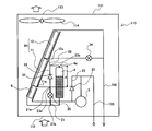
- FIG. 2 is the figure which observed the inside of the outdoor unit of the air conditioning apparatus which concerns on Embodiment 1 of this invention from the side.
- a pipe connecting the discharge port of the compressor 1 and the inlet of the refrigerant of the condenser 10 is shown as a pipe 102.
- a pipe connecting the discharge port of the pump 5 and the inlet of the refrigerant of the expansion valve 2 is shown as a pipe 103.
- the outdoor unit 110 includes, for example, a substantially rectangular parallelepiped casing 111.
- a suction port 112 is formed in the lower part of the housing 111.
- an air outlet 113 is formed in the upper part of the housing 111.
- the blower 114 is accommodated in the vicinity of the blowout port 113, such as at a position facing the blowout port 113. That is, when the blower 114 rotates, outdoor air is sucked into the casing 111 from the suction port 112 at the lower portion of the casing 111. Then, the outdoor air sucked into the housing 111 is blown out of the housing 111 from the air outlet 113 at the top of the housing 111.
- the housing 111 also accommodates the first condenser 11, the second condenser 12, and the subcooling heat exchanger 6.
- the second condenser 12 is disposed in the housing 111 above the first condenser 11.
- the subcooling heat exchanger 6 is disposed below the first condenser 11 in the housing 111.
- the first condenser 11, the second condenser 12, and the subcooling heat exchanger 6 are installed to be inclined with respect to the vertical direction. Compared with the case where the first condenser 11, the second condenser 12, and the subcooling heat exchanger 6 are installed along the vertical direction by installing in an inclined manner in this manner, the first condenser 11, the second condenser
- the heat transfer area of the subcooling heat exchanger 12 can be increased.
- each of the first condenser 11, the second condenser 12, and the subcooling heat exchanger 6 has a plurality of heat transfer fins and a plurality of heat transfer tubes in which the refrigerant flows. It is a heat fin tube type heat exchanger.
- the plurality of heat transfer fins are arranged at predetermined intervals.
- the plurality of heat transfer fins of each of the first condenser 11, the second condenser 12 and the subcooling heat exchanger 6 are arranged at predetermined intervals in the direction orthogonal to the paper surface.
- the plurality of heat transfer tubes pass through each of the plurality of heat transfer fins that constitute the heat exchanger together with the heat transfer tubes. In the case of FIG.
- the plurality of heat transfer tubes of each of the first condenser 11, the second condenser 12 and the subcooling heat exchanger 6 penetrate the plurality of heat transfer fins in the direction orthogonal to the paper surface. That is, in the case of FIG. 2, the plurality of heat transfer tubes of each of the first condenser 11, the second condenser 12 and the subcooling heat exchanger 6 are disposed so as to extend in the direction orthogonal to the paper surface.
- the plurality of heat transfer pipes of the first condenser 11 and the plurality of heat transfer pipes of the second condenser 12 penetrate a common heat transfer fin.
- the plurality of heat transfer fins of the first condenser 11 and the plurality of heat transfer fins of the second condenser 12 are integrated.
- the plurality of heat transfer pipes of the second condenser 12 and the plurality of heat transfer pipes of the subcooling heat exchanger 6 penetrate a common heat transfer fin.
- the plurality of heat transfer fins of the second condenser 12 and the plurality of heat transfer fins of the subcooling heat exchanger 6 are integrated. Treating the second condenser 12 and the subcooling heat exchanger 6 as one heat exchanger when installing the second condenser 12 and the subcooling heat exchanger 6 in the housing 111 by thus configuring the second condenser 12 and the subcooling heat exchanger 6 Can.
- the condenser 10 and the subcooling heat exchanger 6 can be handled as one heat exchanger. Therefore, installation of the subcooling heat exchanger 6 in the housing 111 is facilitated.
- the plurality of heat transfer fins of the second condenser 12 and the plurality of heat transfer fins of the subcooling heat exchanger 6 may be separately configured.
- the receiver 4 is also accommodated in the case 111.
- the receiver 4, the condenser 10 and the bypass pipe 21 have the following positional relationship.
- the second outlet 12 a of the second condenser 12 is disposed at a position higher than the first inlet 4 a of the receiver 4.
- the first pipe 22 connecting the second outlet 12a of the second condenser 12 and the first inlet 4a of the receiver 4 is not raised from the second outlet 12a of the second condenser 12 to the receiver. It can be installed toward the first inlet 4 a of 4. That is, the refrigerant flowing out of the second outlet 12 a of the second condenser 12 can flow toward the first inlet 4 a of the receiver 4 and can flow into the receiver 4 without rising.
- the first outlet 11 a of the first condenser 11 is disposed at a lower position than the first inlet 4 a of the receiver 4. For this reason, the second pipe 23 connecting the first outlet 11 a of the first condenser 11 and the first pipe 22 rises from the first outlet 11 a of the first condenser 11 toward the first pipe 22. Will be installed. Therefore, the refrigerant flowing out of the first outlet 11 a of the first condenser 11 flows upward by the height h from the first outlet 11 a of the first condenser 11 to the first pipe 22 and then flows. It flows into the receiver 4 through the pipe 22.
- the first end 21 a of the bypass pipe 21 is connected to the second pipe 23 at a position lower than the first inlet 4 a of the receiver 4. Therefore, the refrigerant flowing out of the first outlet 11 a of the first condenser 11 flows into the bypass pipe 21 compared to the case where the refrigerant flowing out of the first outlet 11 a of the first condenser 11 flows into the receiver 4 The rise height of the refrigerant at the time of this is low.
- the first end 21 a of the bypass pipe 21 is connected to the second pipe 23 at a position equal to or less than the height of the first outlet 11 a of the first condenser 11. Therefore, the refrigerant flowing out of the first outlet 11 a of the first condenser 11 can flow into the bypass pipe 21 without rising.
- the compressor 1 is driven and the pump 5 is stopped.
- the gaseous refrigerant on the suction port side of the compressor 1 is drawn into the compressor 1 and compressed.
- the gaseous refrigerant compressed by the compressor 1 flows into the first condenser 11 and the second condenser 12.
- the gaseous refrigerant that has flowed into the second condenser 12 is cooled to the outdoor air and is condensed to be a liquid refrigerant, and flows out from the second outlet 12 a. All of the liquid refrigerant flowing out of the second outlet 12 a of the second condenser 12 flows into the receiver 4 through the first pipe 22.
- the gaseous refrigerant that has flowed into the first condenser 11 is cooled by the outdoor air to be condensed into a liquid refrigerant, and flows out from the first outlet 11 a.
- a part of the liquid refrigerant flowing out of the first outlet 11 a of the first condenser 11 flows into the receiver 4 through the second pipe 23 and the first pipe 22.
- the remaining part of the liquid refrigerant that has flowed out from the first outlet 11 a of the first condenser 11 bypasses the receiver 4 by passing through the second pipe 23 and the bypass pipe 21, and the supercooling heat exchanger 6 Flow into
- part of the liquid refrigerant that has flowed out from the first outlet 11 a of the first condenser 11 passes through the second pipe 23 and the bypass pipe 21. It bypasses the receiver 4 and flows into the subcooling heat exchanger 6.
- the first end 21 a of the bypass pipe 21 is connected to the second pipe 23 at a position lower than the first inlet 4 a of the receiver 4. For this reason, the flow of the liquid refrigerant from the first condenser 11 to the bypass pipe 21 is easier to flow than the flow from the first condenser 11 to the receiver 4.
- the air conditioning apparatus 100 according to the first embodiment can suppress the liquid refrigerant from sleeping in the first condenser 11 as compared to the conventional air conditioning apparatus without the bypass pipe 21, and the first condenser 11 Can reduce the amount of liquid refrigerant falling into the For this reason, the air conditioning apparatus 100 according to Embodiment 1 can improve the cooling capacity as compared with the conventional air conditioning apparatus without the bypass pipe 21.
- the first end 21 a of the bypass pipe 21 is connected to the second pipe 23 at a position equal to or less than the height of the first outlet 11 a of the first condenser 11. For this reason, the liquid refrigerant more easily flows from the first condenser 11 to the bypass pipe 21. Therefore, the liquid refrigerant can be further prevented from being stagnated into the first condenser 11, and the cooling capacity of the air conditioner 100 can be further improved.
- the condenser 10 includes the first condenser 11 and the second condenser 12.
- the second condenser 12 is disposed above the first condenser 11, and the second outlet 12 a of the second condenser 12 is disposed at a position higher than the first inlet 4 a of the receiver 4. Therefore, the liquid refrigerant can easily flow from the second condenser 12 to the receiver 4, and the refrigerant can be prevented from being stagnated in the second condenser 12. Therefore, the cooling capacity of the air conditioning apparatus 100 can be further improved.
- the air conditioning apparatus 100 according to Embodiment 1 includes the check valve 31 in the second pipe 23. For this reason, the air conditioning apparatus 100 according to Embodiment 1 can further suppress the liquid refrigerant from falling into the first condenser 11, and can further improve the cooling capacity. Specifically, when the second pipe 23 does not include the check valve 31, the liquid refrigerant that is about to flow out of the first outlet 11a of the first condenser 11 is prevented from flowing out of the first outlet 11a. The pressure of the liquid head ghgh is applied in the direction to make it difficult to flow out from the first outlet 11a.
- ⁇ is the density of the liquid refrigerant
- g is the gravitational acceleration.
- the air conditioner 100 since the air conditioner 100 according to the first embodiment includes the check valve 31 in the second pipe 23, the liquid refrigerant to be discharged from the first outlet 11a of the first condenser 11 is a liquid It is possible to prevent the pressure of the head ⁇ ⁇ ⁇ gh from being applied. Therefore, by providing the second pipe 23 with the check valve 31, it is possible to further suppress the liquid refrigerant from going to the first condenser 11, and to further improve the cooling capacity of the air conditioning apparatus 100.
- the necessary amount of the liquid refrigerant flowing into the receiver 4 flows out of the receiver 4, and the surplus is stored in the receiver 4.
- the liquid refrigerant flowing out of the receiver 4 flows into the supercooling heat exchanger 6 after joining with the liquid refrigerant which has bypassed the receiver 4 through the bypass pipe 21.
- the liquid refrigerant flowing into the subcooling heat exchanger 6 is cooled by the subcooling heat exchanger 6 to increase the degree of subcooling, and then flows out from the subcooling heat exchanger 6.
- the liquid refrigerant flowing out of the subcooling heat exchanger 6 bypasses the pump 5 being stopped through the bypass pipe 25 and the check valve 33 and flows into the expansion valve 2.
- the liquid refrigerant flowing into the expansion valve 2 is expanded to be a gas-liquid two-phase refrigerant, and flows into the evaporator 3.
- the gas-liquid two-phase refrigerant that has flowed into the evaporator 3 absorbs heat from room air and evaporates to become a gaseous refrigerant. After flowing out of the evaporator 3, the gaseous refrigerant is sucked into the compressor 1 and compressed again.
- the pump cycle is executed, for example, when the temperature of the room air which is the heat exchange object of the evaporator 3 is higher than the temperature of the outdoor air which is the heat exchange object of the condenser 10.
- the pump 5 is driven and the compressor 1 is stopped.
- the liquid refrigerant discharged from the pump 5 passes through the expansion valve 2 and flows into the evaporator 3.
- the liquid refrigerant that has flowed into the evaporator 3 absorbs heat from room air and evaporates to become a gaseous refrigerant.
- the gaseous refrigerant that has flowed into the first condenser 11 is cooled by the outdoor air to be condensed into a liquid refrigerant, and flows out from the first outlet 11 a. A part of the liquid refrigerant flowing out of the first outlet 11 a of the first condenser 11 flows into the receiver 4 through the second pipe 23 and the first pipe 22.
- the remaining part of the liquid refrigerant that has flowed out from the first outlet 11 a of the first condenser 11 bypasses the receiver 4 by passing through the second pipe 23 and the bypass pipe 21, and the supercooling heat exchanger 6 Flow into As described above, a part of the liquid refrigerant that has flowed out of the first condenser 11 by the bypass pipe 21 bypasses the receiver 4 so that the first condenser can be compared with a conventional air conditioner that does not include the bypass pipe 21.
- the liquid refrigerant can be prevented from being stagnated in 11, and the amount of the liquid refrigerant that is to be stagnated in the first condenser 11 can be reduced. For this reason, the air conditioning apparatus 100 according to Embodiment 1 can improve the cooling capacity as compared with the conventional air conditioning apparatus without the bypass pipe 21.
- the first end 21 a of the bypass pipe 21 is connected to the second pipe 23 at a position equal to or less than the height of the first outlet 11 a of the first condenser 11. Therefore, as described above, the liquid refrigerant can be further prevented from being stagnated in the first condenser 11, and the cooling capacity of the air conditioner 100 can be further improved.
- the condenser 10 includes the first condenser 11 and the second condenser 12.
- the second condenser 12 is disposed above the first condenser 11, and the second outlet 12 a of the second condenser 12 is disposed at a position higher than the first inlet 4 a of the receiver 4. Therefore, as described above, the refrigerant can be prevented from being stagnated in the second condenser 12, and the cooling capacity of the air conditioner 100 can be further improved.
- the air conditioning apparatus 100 according to Embodiment 1 includes the check valve 31 in the second pipe 23. Therefore, as described above, in the air conditioning apparatus 100 according to the first embodiment, the pressure of the liquid head ghgh is applied to the liquid refrigerant that is about to flow out of the first outlet 11a of the first condenser 11. It can prevent. Therefore, by providing the second pipe 23 with the check valve 31, it is possible to further suppress the liquid refrigerant from going to the first condenser 11, and to further improve the cooling capacity of the air conditioning apparatus 100.
- the necessary amount of the liquid refrigerant flowing into the receiver 4 flows out of the receiver 4, and the surplus is stored in the receiver 4.
- the liquid refrigerant flowing out of the receiver 4 flows into the supercooling heat exchanger 6 after joining with the liquid refrigerant which has bypassed the receiver 4 through the bypass pipe 21.
- the liquid refrigerant flowing into the subcooling heat exchanger 6 is cooled by the subcooling heat exchanger 6 to increase the degree of subcooling, and then flows out from the subcooling heat exchanger 6.
- the liquid refrigerant flowing out of the subcooling heat exchanger 6 is drawn into the pump 5 and discharged again from the pump 5.
- the refrigerant flows from the range in which the pressure is high during the compression cycle to the range in which the pressure is low during the compression cycle.
- the range of high pressure during the compression cycle is the range from the discharge port of the compressor 1 to the inlet of the refrigerant of the expansion valve 2.
- the range of low pressure during the compression cycle is a range from the refrigerant outlet of the expansion valve 2 to the inlet of the compressor 1. That is, when the compressor 1 is stopped, the liquid refrigerant present on the suction port side of the pump 5 flows into the evaporator 3. For this reason, the liquid refrigerant is not supplied to the suction port of the pump 5 for a while after the compressor 1 is stopped, and the pump 5 can not be started.
- the liquid refrigerant flowing out of the first condenser 11 in order for the liquid refrigerant flowing out of the first condenser 11 to rise to the position of the second connection point 23b by natural convection, the liquid refrigerant is within the first condenser 11 to a position higher than the second connection point 23b. It needs to be stored. For this reason, it takes time for the liquid refrigerant to be stored in the receiver 4 in the conventional air conditioner that does not include the bypass pipe 21. That is, in the conventional air conditioner without the bypass pipe 21, it takes time for the liquid refrigerant to flow out from the receiver 4 and for the liquid refrigerant to reach the suction port of the pump 5. For this reason, when switching from a compression cycle to a pump cycle, the time until the pump 5 starts will become long in the conventional air conditioning apparatus which is not provided with the bypass piping 21.
- the liquid refrigerant flowing out of the first condenser 11 can flow through the bypass pipe 21. That is, when the liquid refrigerant flows through the bypass pipe 21, the receiver 4 can be bypassed, and the liquid refrigerant flowing out of the first condenser 11 can flow to the downstream side of the receiver 4. Therefore, when the air conditioning apparatus 100 according to the first embodiment switches from the compression cycle to the pump cycle, the time for supplying the liquid refrigerant to the suction port of the pump 5 can be made shorter than before, and the pump 5 The time to start can be shortened than before.
- the cooling capacity of the air conditioning apparatus 100 can be improved by suppressing the liquid refrigerant from falling into the condenser 10.
- the condenser 10 By setting the condenser 10 to the following configuration, the liquid refrigerant can be further prevented from being stagnated in the condenser 10, and the cooling capacity of the air conditioner 100 can be further improved.
- FIG. 3 is a view showing an example of a condenser of the air conditioning apparatus according to Embodiment 1 of the present invention.
- FIG. 3A is a view of the condenser 10 observed from the side.
- FIG.3 (b) is the Q section enlarged view of Fig.3 (a).
- the condenser 10 shown in FIG. 3 is a heat transfer fin tube type heat exchanger provided with a plurality of heat transfer fins 17 and a plurality of heat transfer pipes 13 in which the refrigerant flows.
- the plurality of heat transfer fins 17 are arranged at predetermined intervals. In the case of FIG. 3, the plurality of heat transfer fins 17 are arranged at predetermined intervals in the direction orthogonal to the paper surface. Further, each of the heat transfer fins 17 has a substantially rectangular shape elongated in the vertical direction, and has a first end 17a and a second end 17b in the short direction.
- the plurality of heat transfer tubes 13 pass through each of the heat transfer fins 17. In the case of FIG. 3, each of the heat transfer tubes 13 penetrates each of the heat transfer fins 17 in the direction orthogonal to the paper surface. That is, in the case of FIG. 3, each of the heat transfer tubes 13 is arranged to extend in the direction orthogonal to the paper surface.
- each of the heat transfer tubes 13 is arrange
- connection pipe 14 connecting the two heat transfer pipes 13, a connection pipe 15, and a connection pipe 16.
- the connection pipe 14 is, for example, a U-shaped pipe, and is a pipe that connects one ends of the heat transfer pipes 13 in adjacent rows.
- the connection pipe 14 is a pipe that connects the ends of the heat transfer pipes 13 in the adjacent rows on the back side of the drawing.
- the connection pipe 14 may be formed integrally with the heat transfer pipe 13 or may be formed separately from the heat transfer pipe 13. When the connection pipe 14 is formed separately from the heat transfer pipe 13, the connection pipe 14 and the heat transfer pipe 13 are connected by brazing or the like.
- connection pipe 15 is, for example, a U-shaped pipe, and is a pipe that connects the other ends of the heat transfer pipes 13 in adjacent rows.
- connection piping 15 is a piping which connects the edge parts on the paper surface front side of the heat transfer tube 13 of the adjacent row.
- the connection pipe 15 may be formed integrally with the heat transfer pipe 13 or may be formed separately from the heat transfer pipe 13. When the connection pipe 15 is formed separately from the heat transfer pipe 13, the connection pipe 15 and the heat transfer pipe 13 are connected by brazing or the like.
- connection piping 16 is, for example, a U-shaped piping, and is a piping that connects the heat transfer tubes 13 in the row closest to the first end 17a and the heat transfer tubes 13 in the row closest to the second end 17b.
- the connection pipe 16 may be formed integrally with the heat transfer pipe 13 or may be formed separately from the heat transfer pipe 13. When the connection pipe 16 is formed separately from the heat transfer pipe 13, the connection pipe 15 and the heat transfer pipe 13 are connected by brazing or the like.
- connection pipe 14 In the condenser 10 configured in this manner, a plurality of heat transfer pipes 13 are connected to the connection pipe 14, the connection pipe 15, and the connection pipe 16 to flow as shown by the solid arrows in FIG. 3 (b). A passage 18 is formed.
- At least one of the heat transfer tubes 13 in the row closest to the first end 17a is connected to a branch header (not shown) of the condenser 10, and the refrigerant flows from the branch header.
- One such heat transfer tube 13 is referred to as a heat transfer tube 131.
- at least one of the heat transfer tubes 13 in the row closest to the second end 17b is connected to the unshown joining header of the condenser 10, and the refrigerant flows out to the joining header.
- One such heat transfer tube 13 is referred to as a heat transfer tube 13 n.
- the refrigerant outlet of the condenser 10 shown in FIG. 3 is provided in a merging header (not shown).
- the above-mentioned heat transfer pipe 131 is a heat transfer pipe 13 in a row on the second end 17 b side by one line from the heat transfer pipe 131, and is connected to the heat transfer pipe 13 arranged one step below the heat transfer pipe 131 by connecting piping 14. It is connected.
- the heat transfer pipe 13 connected to the heat transfer pipe 131 by the connection pipe 14 is shown as a heat transfer pipe 132.
- the heat transfer pipe 132 is connected to the heat transfer pipe 13 in a row on the second end 17 b side of the heat transfer pipe 132 by one connection pipe 15 to the heat transfer pipe 13 disposed one step lower than the heat transfer pipe 132. It is done.
- the heat transfer pipe 13 connected with the heat transfer pipe 132 by the connection pipe 15 is shown as the heat transfer pipe 133.
- the heat transfer pipe 133 is connected to the heat transfer pipe 13 of the row closest to the second end 17 b and is connected to the heat transfer pipe 13 disposed one step lower than the heat transfer pipe 133 by a connection pipe 14.
- the heat transfer pipe 13 connected with the heat transfer pipe 133 by the connection pipe 14 is shown as a heat transfer pipe 134.
- the heat transfer pipe 134 is connected to the heat transfer pipe 13 of the row closest to the first end 17 a and is connected to the heat transfer pipe 13 disposed below the heat transfer pipe 134 by a connection pipe 16.
- the heat transfer pipe 13 connected to the heat transfer pipe 134 by the connection pipe 16 is shown as a heat transfer pipe 135.
- the heat transfer pipe 135 is the heat transfer pipe 13 disposed three stages lower than the heat transfer pipe 131.
- the heat transfer pipe 13 is connected with the heat transfer pipe 131 to the heat transfer pipe 13 n by the connection pipe 14, the connection pipe 15 and the connection pipe 16 as described above, whereby the flow path 18 is formed.
- the condenser 10 When the condenser 10 is installed such that the longitudinal direction of the heat transfer fins 17 is along the vertical direction, the flow path 18 is horizontal from the upstream side to the downstream side in the flow direction of the refrigerant flowing through the flow path 18. Or it is in the state of tilting downward. For this reason, the condenser 10 shown in FIG. 3 has no location where the refrigerant rises by rising in the flow passage 18, and the refrigerant can flow smoothly through the flow passage 18, so that the liquid refrigerant stagnates inside. It can be suppressed.
- the angle of the connection piping 16 and a horizontal direction is (alpha).
- the connection pipe 16 constitutes a portion of the flow path 18 that flows from the second end 17 b to the first end 17 a. Therefore, even when the condenser 10 is installed such that the longitudinal direction of the heat transfer fins 17 is inclined toward the second end 17b with respect to the vertical direction, the angle between the longitudinal direction of the heat transfer fins 17 and the vertical direction Is less than or equal to ⁇ , the flow path 18 is inclined horizontally or downwardly from the upstream side to the downstream side in the flow direction of the refrigerant flowing through the flow path 18. For this reason, the condenser 10 shown in FIG.
- the condenser 10 shown in FIG. 3 rises in the flow path 18 even when the condenser 10 is installed such that the longitudinal direction of the heat transfer fins 17 is inclined toward the first end 17a with respect to the vertical direction. Since there is no place where the refrigerant flows and the refrigerant can flow smoothly through the flow path 18, it is possible to further suppress the liquid refrigerant from being stagnated inside.
- the air conditioning apparatus 100 includes the refrigerant circulation circuit 101 in which the refrigerant circulates.
- the refrigerant circulation circuit 101 includes a compressor 1, a condenser 10, an expansion valve 2, an evaporator 3, a receiver 4 connected between the condenser 10 and the expansion valve 2 for storing surplus refrigerant, a receiver 4 and an expansion valve. And a pump 5 connected between them.
- the air conditioning apparatus 100 drives the compressor 1 and stops the pump 5 to cause the refrigerant circulation circuit 101 to circulate the refrigerant, and the pump 5 to drive the compressor 1 to stop the refrigerant circulation circuit 101. And a pump cycle for circulating the refrigerant.
- the receiver 4 is provided with a first inlet 4 a which is an inlet through which the refrigerant flows into the receiver 4.
- the condenser 10 is provided with a first outlet 11 a, which is an outlet from which the refrigerant flows out of the condenser 10, at a position lower than the first inlet 4 a of the receiver 4.
- the refrigerant circulation circuit 101 includes a bypass pipe 21. At a position lower than the first inlet 4 a of the receiver 4, the first end 21 a, which is the end on the refrigerant inlet side of the bypass pipe 21, is the first outlet 11 a of the condenser 10 and the first inlet of the receiver 4. It is connected between 4a.
- a second end 21 b which is an end on the refrigerant outflow side of the bypass pipe 21 is connected between the receiver 4 and the pump 5.
- the air conditioning apparatus 100 according to Embodiment 1 can bypass the receiver 4 by the bypass pipe 21 and supply the liquid refrigerant that has flowed out of the condenser 10 to the pump 5. For this reason, the air conditioning apparatus 100 according to the first embodiment can shorten the time to supply the liquid refrigerant to the suction port of the pump 5 as compared to the prior art when the operating state is switched from the compression cycle to the pump cycle. The time until the pump 5 starts up can be made shorter than before.
- the inventors use the actual machine provided with the refrigerant circulation circuit 101 according to the first embodiment, and from the compression cycle to the pump cycle, in the case where the bypass pipe 21 is provided and in the case where the bypass pipe 21 is not provided.
- the time until the pump 5 starts after switching was compared.
- the time taken for the pump 5 to start after switching from the compression cycle to the pump cycle is reduced by 30 seconds as compared to the case where the bypass pipe 21 is not provided. .
- the air conditioner 100 according to the first embodiment includes the bypass pipe 21, as described above, the liquid refrigerant stagnates in the condenser 10 in both the compression cycle and the pump cycle. It can suppress rather than before and can improve cooling capacity rather than before.
- the inventors compared the cooling capacity between the case where the bypass pipe 21 is provided and the case where the bypass pipe 21 is not provided, using the actual device provided with the refrigerant circulation circuit 101 according to the first embodiment.
- the cooling capacity was improved by 2% both in the compression cycle and in the pump cycle as compared with the case where the bypass pipe 21 was not provided.
- the refrigerant circulation circuit 101 shown in Embodiment 1 is an example. If the refrigerant circulation circuit 101 includes the bypass pipe 21 described above, the configuration of the refrigerant circulation circuit 101 may be changed as appropriate according to the cooling capacity and the like required for the air conditioner 100. In the second embodiment, one modified example of the refrigerant circuit 101 is introduced. In the second embodiment, items that are not particularly described are assumed to be the same as in the first embodiment, and functions and configurations that are the same as in the first embodiment are described using the same reference numerals.
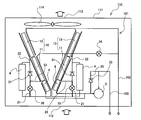
- FIG. 4 is the figure which observed the inside of the outdoor unit of the air conditioning apparatus which concerns on Embodiment 2 of this invention from the side.
- the air conditioner 100 according to the second embodiment includes two condensers 10 and two subcooling heat exchangers 6 in order to increase the heat exchange capacity of the condenser 10 and the subcooling heat exchanger 6.
- the condenser 10, the subcooling heat exchanger 6, the receiver 4 and the bypass pipe 21 are combined into one set.
- the refrigerant circulation circuit 101 of the air conditioner 100 includes two sets of the condenser 10, the subcooling heat exchanger 6, the receiver 4 and the bypass pipe 21. Each set is connected in parallel between the discharge port of the compressor 1 and the suction port of the pump 5.
- the condenser 10 according to the second embodiment includes the first condenser 11 and the second condenser 12. That is, the refrigerant circuit 101 according to the second embodiment includes the two first condensers 11 and the two second condensers 12. The two first condensers 11 are connected in parallel to the discharge port of the compressor 1. The second condenser 12 is connected in parallel to the discharge port of the compressor 1.
- the air conditioning apparatus 100 according to Embodiment 2 includes a bypass pipe 21 in each set. For this reason, the air conditioning apparatus 100 according to Embodiment 2 can supply part of the liquid refrigerant flowing out of the condenser 10 to the pump 5 by bypassing the receiver 4 in each set. Therefore, in the air conditioner 100 according to the second embodiment, the pump 5 is activated when the operating state is switched from the compression cycle to the pump cycle, as compared with the case where each set does not include the bypass pipe 21. Time can be shortened. Further, the air conditioning apparatus 100 according to the second embodiment can improve the cooling capacity both in the compression cycle and in the pump cycle, as compared to the case where each set does not include the bypass pipe 21.
Landscapes
- Engineering & Computer Science (AREA)
- Mechanical Engineering (AREA)
- General Engineering & Computer Science (AREA)
- Physics & Mathematics (AREA)
- Thermal Sciences (AREA)
- Life Sciences & Earth Sciences (AREA)
- Sustainable Development (AREA)
- Chemical & Material Sciences (AREA)
- Combustion & Propulsion (AREA)
- Air Conditioning Control Device (AREA)
Abstract
Un dispositif de climatisation selon la présente invention comprend un compresseur, un condenseur, une soupape de détente, un évaporateur, un récepteur pour stocker le fluide frigorigène en excès et raccordé entre le condenseur et la soupape de détente, et une pompe raccordée entre le récepteur et la soupape de détente, et exécute un cycle de réfrigération et un cycle de pompe. Le récepteur est équipé d'une première entrée, qui est une entrée permettant à un fluide frigorigène de s'écouler dans le récepteur. Le condenseur comporte une première sortie, qui est une sortie permettant à un fluide frigorigène de s'écouler hors du condenseur, ladite première sortie étant à une position inférieure à celle de la première entrée. Un circuit de circulation de fluide frigorigène est équipé d'un tuyau de dérivation dont une première extrémité, c'est-à-dire une extrémité côté entrée de fluide frigorigène, est reliée entre la première sortie et la première entrée à une position inférieure à la première entrée, et dont une seconde extrémité, c'est-à-dire une extrémité côté sortie de fluide frigorigène, est reliée entre le récepteur et la pompe.
Priority Applications (2)
| Application Number | Priority Date | Filing Date | Title |
|---|---|---|---|
| JP2019567806A JP6869382B2 (ja) | 2018-01-29 | 2018-01-29 | 空気調和装置 |
| PCT/JP2018/002688 WO2019146099A1 (fr) | 2018-01-29 | 2018-01-29 | Dispositif de climatisation |
Applications Claiming Priority (1)
| Application Number | Priority Date | Filing Date | Title |
|---|---|---|---|
| PCT/JP2018/002688 WO2019146099A1 (fr) | 2018-01-29 | 2018-01-29 | Dispositif de climatisation |
Publications (1)
| Publication Number | Publication Date |
|---|---|
| WO2019146099A1 true WO2019146099A1 (fr) | 2019-08-01 |
Family
ID=67394590
Family Applications (1)
| Application Number | Title | Priority Date | Filing Date |
|---|---|---|---|
| PCT/JP2018/002688 Ceased WO2019146099A1 (fr) | 2018-01-29 | 2018-01-29 | Dispositif de climatisation |
Country Status (2)
| Country | Link |
|---|---|
| JP (1) | JP6869382B2 (fr) |
| WO (1) | WO2019146099A1 (fr) |
Cited By (1)
| Publication number | Priority date | Publication date | Assignee | Title |
|---|---|---|---|---|
| EP4271154A1 (fr) * | 2022-04-29 | 2023-11-01 | Huawei Digital Power Technologies Co., Ltd. | Hôte d'alimentation et système d'alimentation électrique |
Citations (10)
| Publication number | Priority date | Publication date | Assignee | Title |
|---|---|---|---|---|
| JPS561063U (fr) * | 1980-06-19 | 1981-01-07 | ||
| JPH11316058A (ja) * | 1998-02-23 | 1999-11-16 | Mitsubishi Electric Corp | 空気調和機 |
| CA2298373A1 (fr) * | 2000-02-11 | 2001-08-11 | Joseph Antoine Michel Grenier | Systeme de refroidissement avec refroidissement naturel accru |
| US20130098086A1 (en) * | 2011-04-19 | 2013-04-25 | Liebert Corporation | Vapor compression cooling system with improved energy efficiency through economization |
| JP2013092318A (ja) * | 2011-10-27 | 2013-05-16 | Hitachi Appliances Inc | 空気調和装置 |
| JP2013113533A (ja) * | 2011-11-30 | 2013-06-10 | Hitachi Appliances Inc | 空気調和機および空気調和機の運転方法 |
| JP2013257086A (ja) * | 2012-06-13 | 2013-12-26 | Hitachi Appliances Inc | 空気調和機及びその制御方法 |
| US20140157821A1 (en) * | 2012-12-07 | 2014-06-12 | Liebert Corporation | Receiver tank purge in vapor compression cooling system with pumped refrigerant economization |
| JP2014163530A (ja) * | 2013-02-21 | 2014-09-08 | Hitachi Appliances Inc | 空気調和装置 |
| CN106440437A (zh) * | 2016-11-24 | 2017-02-22 | 南京佳力图机房环境技术股份有限公司 | 一种新型自然冷源制冷系统及其控制方法 |
-
2018
- 2018-01-29 JP JP2019567806A patent/JP6869382B2/ja not_active Expired - Fee Related
- 2018-01-29 WO PCT/JP2018/002688 patent/WO2019146099A1/fr not_active Ceased
Patent Citations (10)
| Publication number | Priority date | Publication date | Assignee | Title |
|---|---|---|---|---|
| JPS561063U (fr) * | 1980-06-19 | 1981-01-07 | ||
| JPH11316058A (ja) * | 1998-02-23 | 1999-11-16 | Mitsubishi Electric Corp | 空気調和機 |
| CA2298373A1 (fr) * | 2000-02-11 | 2001-08-11 | Joseph Antoine Michel Grenier | Systeme de refroidissement avec refroidissement naturel accru |
| US20130098086A1 (en) * | 2011-04-19 | 2013-04-25 | Liebert Corporation | Vapor compression cooling system with improved energy efficiency through economization |
| JP2013092318A (ja) * | 2011-10-27 | 2013-05-16 | Hitachi Appliances Inc | 空気調和装置 |
| JP2013113533A (ja) * | 2011-11-30 | 2013-06-10 | Hitachi Appliances Inc | 空気調和機および空気調和機の運転方法 |
| JP2013257086A (ja) * | 2012-06-13 | 2013-12-26 | Hitachi Appliances Inc | 空気調和機及びその制御方法 |
| US20140157821A1 (en) * | 2012-12-07 | 2014-06-12 | Liebert Corporation | Receiver tank purge in vapor compression cooling system with pumped refrigerant economization |
| JP2014163530A (ja) * | 2013-02-21 | 2014-09-08 | Hitachi Appliances Inc | 空気調和装置 |
| CN106440437A (zh) * | 2016-11-24 | 2017-02-22 | 南京佳力图机房环境技术股份有限公司 | 一种新型自然冷源制冷系统及其控制方法 |
Cited By (1)
| Publication number | Priority date | Publication date | Assignee | Title |
|---|---|---|---|---|
| EP4271154A1 (fr) * | 2022-04-29 | 2023-11-01 | Huawei Digital Power Technologies Co., Ltd. | Hôte d'alimentation et système d'alimentation électrique |
Also Published As
| Publication number | Publication date |
|---|---|
| JPWO2019146099A1 (ja) | 2020-11-19 |
| JP6869382B2 (ja) | 2021-05-12 |
Similar Documents
| Publication | Publication Date | Title |
|---|---|---|
| US10443944B2 (en) | Heat exchanger and air conditioning device | |
| US11747059B2 (en) | Heat exchanger | |
| US9574806B2 (en) | Heat exchanger and air conditioning apparatus | |
| US10655917B2 (en) | Heat exchanger and air conditioning device | |
| US11603997B2 (en) | Heat exchanger and air conditioner | |
| JPWO2010086954A1 (ja) | 空気調和装置及び冷凍機油の返油方法 | |
| JP2009127939A (ja) | ヒートポンプ式空気調和機 | |
| WO2012043377A1 (fr) | Circuit de réfrigération | |
| US12392530B2 (en) | Chiller system with multiple compressors | |
| KR102092568B1 (ko) | 차량용 에어컨시스템 | |
| JP7113974B2 (ja) | 空気調和機 | |
| KR20130102478A (ko) | 히트펌프식 급탕장치 | |
| WO2019146099A1 (fr) | Dispositif de climatisation | |
| KR100883600B1 (ko) | 공기조화기 | |
| US12078427B2 (en) | Heat exchanger and air conditioner having the same | |
| JP6641070B1 (ja) | 空気調和機 | |
| US20200200476A1 (en) | Heat exchanger | |
| US20070062214A1 (en) | Accumulator of refrigeration cycle system | |
| WO2022255358A1 (fr) | Dispositif de climatisation | |
| KR101416936B1 (ko) | 공기조화기 | |
| JP5796588B2 (ja) | オープンショーケース | |
| JP4609230B2 (ja) | エジェクタ式サイクル | |
| KR20250109324A (ko) | 시동시의 공조기 열교환기의 용이한 오일회수 구성 | |
| JP4591829B2 (ja) | 冷凍装置 | |
| JP5849697B2 (ja) | 室外ユニット |
Legal Events
| Date | Code | Title | Description |
|---|---|---|---|
| 121 | Ep: the epo has been informed by wipo that ep was designated in this application |
Ref document number: 18902483 Country of ref document: EP Kind code of ref document: A1 |
|
| ENP | Entry into the national phase |
Ref document number: 2019567806 Country of ref document: JP Kind code of ref document: A |
|
| NENP | Non-entry into the national phase |
Ref country code: DE |
|
| 122 | Ep: pct application non-entry in european phase |
Ref document number: 18902483 Country of ref document: EP Kind code of ref document: A1 |