WO2019146128A1 - 採精容器 - Google Patents
採精容器 Download PDFInfo
- Publication number
- WO2019146128A1 WO2019146128A1 PCT/JP2018/007444 JP2018007444W WO2019146128A1 WO 2019146128 A1 WO2019146128 A1 WO 2019146128A1 JP 2018007444 W JP2018007444 W JP 2018007444W WO 2019146128 A1 WO2019146128 A1 WO 2019146128A1
- Authority
- WO
- WIPO (PCT)
- Prior art keywords
- sperm
- container
- lid
- inner container
- recovery
- Prior art date
- Legal status (The legal status is an assumption and is not a legal conclusion. Google has not performed a legal analysis and makes no representation as to the accuracy of the status listed.)
- Ceased
Links
Images


Classifications
-
- A—HUMAN NECESSITIES
- A61—MEDICAL OR VETERINARY SCIENCE; HYGIENE
- A61B—DIAGNOSIS; SURGERY; IDENTIFICATION
- A61B10/00—Instruments for taking body samples for diagnostic purposes; Other methods or instruments for diagnosis, e.g. for vaccination diagnosis, sex determination or ovulation-period determination; Throat striking implements
- A61B10/0045—Devices for taking samples of body liquids
- A61B10/0058—Devices for taking samples of body liquids for taking sperm samples
-
- B—PERFORMING OPERATIONS; TRANSPORTING
- B65—CONVEYING; PACKING; STORING; HANDLING THIN OR FILAMENTARY MATERIAL
- B65D—CONTAINERS FOR STORAGE OR TRANSPORT OF ARTICLES OR MATERIALS, e.g. BAGS, BARRELS, BOTTLES, BOXES, CANS, CARTONS, CRATES, DRUMS, JARS, TANKS, HOPPERS, FORWARDING CONTAINERS; ACCESSORIES, CLOSURES, OR FITTINGS THEREFOR; PACKAGING ELEMENTS; PACKAGES
- B65D77/00—Packages formed by enclosing articles or materials in preformed containers, e.g. boxes, cartons, sacks or bags
- B65D77/04—Articles or materials enclosed in two or more containers disposed one within another
-
- A—HUMAN NECESSITIES
- A61—MEDICAL OR VETERINARY SCIENCE; HYGIENE
- A61B—DIAGNOSIS; SURGERY; IDENTIFICATION
- A61B10/00—Instruments for taking body samples for diagnostic purposes; Other methods or instruments for diagnosis, e.g. for vaccination diagnosis, sex determination or ovulation-period determination; Throat striking implements
- A61B10/0096—Casings for storing test samples
-
- A—HUMAN NECESSITIES
- A61—MEDICAL OR VETERINARY SCIENCE; HYGIENE
- A61B—DIAGNOSIS; SURGERY; IDENTIFICATION
- A61B17/00—Surgical instruments, devices or methods
- A61B17/42—Gynaecological or obstetrical instruments or methods
- A61B17/425—Gynaecological or obstetrical instruments or methods for reproduction or fertilisation
- A61B17/43—Gynaecological or obstetrical instruments or methods for reproduction or fertilisation for artificial insemination
-
- A—HUMAN NECESSITIES
- A61—MEDICAL OR VETERINARY SCIENCE; HYGIENE
- A61D—VETERINARY INSTRUMENTS, IMPLEMENTS, TOOLS, OR METHODS
- A61D19/00—Instruments or methods for reproduction or fertilisation
- A61D19/02—Instruments or methods for reproduction or fertilisation for artificial insemination
- A61D19/022—Containers for animal semen, e.g. pouches or vials ; Methods or apparatus for treating or handling animal semen containers, e.g. filling or closing
-
- A—HUMAN NECESSITIES
- A01—AGRICULTURE; FORESTRY; ANIMAL HUSBANDRY; HUNTING; TRAPPING; FISHING
- A01N—PRESERVATION OF BODIES OF HUMANS OR ANIMALS OR PLANTS OR PARTS THEREOF; BIOCIDES, e.g. AS DISINFECTANTS, AS PESTICIDES OR AS HERBICIDES; PEST REPELLANTS OR ATTRACTANTS; PLANT GROWTH REGULATORS
- A01N1/00—Preservation of bodies of humans or animals, or parts thereof
- A01N1/10—Preservation of living parts
- A01N1/14—Mechanical aspects of preservation; Apparatus or containers therefor
- A01N1/146—Non-refrigerated containers specially adapted for transporting or storing living parts whilst preserving
Definitions
- the present invention relates to a sperm collection container.
- sperm is collected in a cylindrical, wide-mouthed transparent plastic collection container (a container for collecting and storing sperm), and the collection container
- ART reproduction assistance medical treatment
- sperm is collected in a cylindrical, wide-mouthed transparent plastic collection container (a container for collecting and storing sperm), and the collection container
- the patient brings from home to the medical institution.
- the semen brought by the patient is stored in a state of being collected in a sperm collection container until the sperm examination or predetermined treatment is performed.
- this conventional cylindrical sperm collection container has a large bottom area, so the semen diffuses into the container, and also when transported Due to vibration and inclination of the semen, semen may be attached to the wall, and it has been difficult to collect semen from the sperm collection container sufficiently.
- patent document 1 aims at the compact packaging etc. in an unused state, and does not aim at compactization of the sperm production container at the time of transport and storage of sperm.
- Patent Document 1 does not disclose at all about suppressing the deterioration of sperm.
- the present invention has been made in view of the above-mentioned circumstances, and it is possible to provide a sperm collection container which is excellent in suppressing the deterioration of the spermatozoa and which can efficiently collect the spermatozoa. is there.
- a sperm production container comprises a container body having an inner container for containing sperm and an outer container for covering the inner container, and a lid mounted on the container body.
- the inner container has an inlet for receiving the sperm and a bottomed reservoir for storing the sperm at a smaller diameter than the inlet, and the bottom of the reservoir is for collecting the sperm.
- the sperm collection unit is sometimes provided that is occluded and is opened by inserting a piercing member at the time of sperm collection, and the lid is used to reduce the volume of the inner container. It is characterized by having an inner lid inserted and arranged inside.
- a sperm collection container which is excellent in suppressing the deterioration of the spermatozoa and which can efficiently collect the spermatozoa.
- FIG. 2 is a view showing a lid main body of the lid shown in FIG.
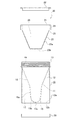
- FIG. 1A is a front view of the sperm collection container 1 according to the first embodiment
- FIG. 1B is a front view of a state in which each part of the germ collection container 1 is separated.
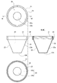
- FIG. 2 is a plan view, a front view, a bottom view, a cross-sectional view taken along the line AA 'of the plan view, and an enlarged cross-sectional view of the vicinity of the recovery portion shown in FIGS. 1A and 1B.
- FIG. 3 is a plan view, a front view, a bottom view, and a sectional view taken along line BB ′ of the plan view of the lid body 21 of the lid 20 shown in FIGS. 1A and 1B.
- the patient himself / her who receives ART, and a medical worker such as a doctor and a reproduction assisted medical embryo culture person can be mentioned.
- the patient himself (male) picks up sperm at home using the blood collection container 1 of the present embodiment, and the patient himself or his wife carries it to the medical institution.
- sperm may be collected at a medical institution.
- sperm is stored in the state of being contained in the sperm collection container 1 until a doctor or the like performs various treatments for sperm examination and artificial insemination.
- the sperm production container 1 of this embodiment efficiently recovers sperm while suppressing the deterioration of the sperm due to oxidation, temperature change, aging (temporal aging) until each treatment for ART from the sperm production. Used to
- the sperm production container 1 includes a container body 10 for collecting sperm (semen), and a lid 20 attached to the mouth of the container body 10. And a lower lid 30 attached to the lower end of the container body 10.
- the container main body 10 has a bottomed inner container 11 for storing collected sperm, and an outer container 12 for covering the inner container 11, and has a double structure.
- the inner container 11 and the outer container 12 are integrally connected at the upper end, and a screw groove 13 for mounting the lid 20 is provided on the outer periphery of the connection portion.
- the inner container 11 is provided with an inlet 14 for sperm and a reservoir 15 for sperm as shown in each drawing of FIG.
- the inlet 14 and the reservoir 15 are connected by a frusto-conical (funnel-like) tapered portion 16 having a large diameter on the inlet 14 side and a gradually smaller diameter toward the reservoir 15.
- the insertion port 14 has a large circular shape in a plan view, so that it is easy to collect sperm.
- the inner diameter of the reservoir 15 is smaller than the inner diameter of the inlet 14.
- the storage portion 15 has a wall portion 15a and a bottom portion 15b which protrudes downward in a circular arc shape in cross section from the lower end of the wall portion 15a.
- the reservoir 15 is frusto-conical.
- the bottom portion 15 b is provided with a recovery portion 15 c for recovering the sperm stored in the storage portion 15 by a recovery unit such as the syringe 2 (see FIG. 5).
- a recovery unit such as the syringe 2
- the vicinity of the center of the bottom portion 15b is a circular thin portion, and the thin portion is a recovery portion 15c.
- the tip of the syringe 2 as the piercing means or the tip of the needle 3 (see FIG. 5) attached to the syringe 2 can be easily pierced and opened (see FIG. 5).
- the entire recovery part 15c is made thin, but it is not limited to this, and only the outline of the circular recovery part 15c may be made thin. Even in this case, the thin portion can be easily broken by the tip of the syringe 2 or the needle 3 to open the recovery portion 15c.
- sperm since a single production of sperm (sperm) is 3 to 10 cc, in a conventional sperm production container having the same inner diameter from the inlet to the reservoir, the sperm is diffused and the sperm layer becomes thin Because it adheres to the wall surface, it is difficult to collect, and it is also difficult to confirm the amount of sperm production.
- the sperm layer in the storage part 15 can be made thicker by making the internal diameter of the storage part 15 into a small diameter rather than the insertion port 14 like the inner container 11 of this embodiment. Therefore, while becoming easy to collect
- the tapered portion 16 collects sperm introduced from the inlet 14 and guides the collected sperm to the reservoir 15.
- by performing mirror finishing on the inner wall surface of the tapered portion 16 it is possible to promote the flow of sperm and suppress adhesion of the sperm to the inner wall surface, and it is possible to lead smoothly by the storage portion 15.
- the outer container 12 protects the inner container 11 and has a cylindrical outer peripheral wall 12a which can cover the entire inner container 11 and does not have a bottom, and is removable at the opening 12b at the lower end of the outer peripheral wall 12a.
- the lower lid 30 is attached to the
- the protection performance of the thin-walled recovery portion 15c is improved, and the articles in the bag collide with the recovery portion 15c to suppress accidental breakage or the like.
- the air layer in the space portion 17 partitioned by the outer peripheral wall 12 a of the outer container 12 and the lower lid 30 and the frusto-conical inner container 11 is thermally insulated It functions as a material. Due to the heat insulation effect of the air layer, the sperm in the storage section 15 is not unnecessarily influenced by the outside air temperature, and a rapid temperature change can be suppressed to maintain a predetermined temperature.
- expanded polystyrene foam or the like having thermal insulation may be accommodated in the space portion 17, and vibration or impact to the inner container 11 at the time of transportation or the like can be alleviated.
- the sperm can be recovered from the recovery unit 15c. At this time, since it is not necessary to remove the lid 20, it is possible to avoid contact between the sperm and the outside air, and it is possible to effectively suppress the oxidation of the sperm and the invasion of dust and the like.
- the storage temperature of sperm is preferably 20 to 35 ° C., most preferably about 25 ° C., and the effect of suppressing the deterioration of sperm due to aging can be improved.
- the average human body temperature is about 37 ° C.
- the temperature of sperm at the time of collection is about 35 ° C.
- the size of the container body 10 is not particularly limited. For example, it is desirable that the outer diameter be 50 to 100 mm and the height be 70 to 150 mm. By setting it as such a size, the container main body 10 can be stably gripped, and the handling property at the time of collection and examination improves. Moreover, since the insertion port 14 of the inner container 11 can be made wide, it can be made easy to collect sperm. Moreover, even if it stores in a bag etc., while being bulky, while being excellent also in portability, the stability when placing in a storage place is also improved.
- the tapered portion 16 has a frusto-conical shape rotated about the rotation axis O.
- the inclination angle of the wall surface with respect to the rotation axis O It is desirable that ⁇ be 10 ° to 30 ° (that is, 20 ° to 60 ° for the apex angle of the cone, and 60 ° to 80 ° for the elevation angle).
- the sperm can be smoothly flowed down toward the storage portion 15 on the inclined inner wall surface, and the sperm can be efficiently collected without waste.
- the height of the container body 10 is about 83 mm, and the outer diameter (the outer diameter of the outer container 12) is about 57 mm.
- the inlet 14 has an inner diameter of about 55 mm and is opened larger than in the past to make it easier to collect sperm.
- the reservoir 15 has a maximum inner diameter of about 23 mm on the upper end side and a height of about 34 mm, and the volume is about 14 ml.
- the tapered portion 16 has a height of about 38 mm and an inclination angle ⁇ of about 23 ° (elevation angle of about 67 °).
- the material of the container body 10 is not particularly limited, but a synthetic resin (plastic) such as polypropylene can be suitably used, and the container body 10 is lightweight and excellent in impact resistance, water resistance, etc. You can get it. Also, the container body 10 made of such a material may be transparent or translucent or opaque.
- a container body 10 in which the inner container 11 and the outer container 12 are integrally connected is obtained by mold forming using polypropylene. Thereby, the container main body 10 can be easily manufactured at low cost.
- the outer surface of the container body 10 is processed to be translucent so as to be translucent.
- the collected sperm can be hidden from the eyes of a third party, and the mental burden of the patient etc. can be alleviated.
- by making it semi-transparent it is possible for a patient, a doctor or the like to visually check the amount and status of spermatozoa in the reservoir 15 at a close distance.
- the container body 10 when the container body 10 is made opaque, the light shielding property and the shielding property are improved, and the deterioration of the spermatozoa due to the ultraviolet light can be suppressed, and the spermatozoa in the reservoir 15 is concealed from the eyes of the third party Excellent.
- the container main body 10 when the container main body 10 is made transparent, it becomes easier to confirm the amount of sperm production and the state. Thus, even if it is transparent, the collected sperm can be concealed from the eyes of a third party by storing the sperm collection container 1 in a cloth bag, a paper bag, a storage container or the like.
- the lid 20 is attached to the opening of the container body 10 as described above to seal the container body 10.
- the lid 20 includes a lid main body 21 detachably mounted on the container main body 10 and an upper lid 22 detachably mounted on the lid main body 21 as shown in each drawing of FIG. 3.
- the lid body 21 is provided with an inner lid 23 inserted and disposed in the inner container 11 so as to project downward so as to reduce the volume of the inner container 11.
- a gripping portion 24 which the patient or the like grips when attaching and detaching the lid 20 is provided on the outside of the inner lid 23 with an interval.
- a screw groove 25 screwed to the screw groove 13 of the container main body 10 is provided on the inner periphery of the grip portion 24.
- packing etc. may be provided inside the holding part 24, and the prevention effect of the leak of a spermatozoon and the penetration
- the inner lid 23 is a hollow body projecting in a frusto-conical shape in the direction of the storage portion 15 of the inner container 11 corresponding to the shape of the tapered portion 16 so as to be inserted into the tapered portion 16 of the inner container 11. It is configured.
- the inner lid 23 comprises a hollow body having a frusto-conical wall 23a, a flat bottom 23b, and a space 26 surrounded by the wall 23a and the bottom 23b.
- an upper lid 22 is detachably attached to an upper portion of the lid main body 21 on the opposite side to the insertion side into the inner container 11.
- the space 26 of the inner lid 23 is isolated from the outside. The heat insulation effect of the air layer in the space portion 26 can further improve the suppression effect of the temperature change of the sperm in the storage portion 15.
- the upper lid 22 detachable, it becomes possible to accommodate expanded polystyrene and the like in the space 26. Furthermore, the heat storage material, the heat generating material, the heat insulating material, etc. can be accommodated in the space 26 according to the outside air temperature or the like. Therefore, even if the outside air temperature is excessively high or low, the temperature in the container body 10 can be freely controlled so as not to be affected by these.
- FIG. 4 is a diagram for explaining a breeding procedure using the breeding container 1
- FIG. 5 is a diagram for explaining a collection procedure of sperm from the breeding container 1. As shown in FIG. 4, FIG. 4 is a diagram for explaining a breeding procedure using the breeding container 1, and FIG. 5 is a diagram for explaining a collection procedure of sperm from the breeding container 1. As shown in FIG. 4, FIG. 4 is a diagram for explaining a breeding procedure using the breeding container 1, and FIG. 5 is a diagram for explaining a collection procedure of sperm from the breeding container 1. As shown in FIG.
- the lid 20 is removed from the sperm collection container 1, and the patient collects the sperm S using the container main body 10.
- the spermatozoon S flows smoothly down the inner wall surface of the tapered portion 16 which is inclined at an acute angle and is mirror-finished directly from the wide open inlet 14 of the inner container 11 and drops into the storage portion 15 for storage. Ru.
- the lid 20 When the collection of the spermatozoa S is completed, the lid 20 is disposed at the mouth of the container body 10, and the screw groove 13 of the container body 10 and the screw groove 25 of the lid 20 are screwed together. Mount 20 (see the right figure in Fig. 4). Thereby, the inner lid 23 is inserted and disposed in the tapered portion 16 of the inner container 11, the volume of the air layer in the inner container 11 is reduced, and the contact between the sperm S in the storage portion 15 and the air is minimized. Can.
- the sperm collection container 1 which accommodated sperm S in a bag etc.
- a patient etc. can carry easily to a medical institution.
- a bag made of paper, cloth, resin, or the like visual recognition from a third party can be suppressed.
- it may be housed in a dedicated storage container housing a cold storage bag, a heat insulating material, a temperature control device, etc., and temperature change can be suppressed and temperature management can be facilitated.
- the sperm S can be stored in a state in which the sperm S is accommodated in the sperm collection container 1 until the examination or treatment is performed.
- the lower lid 30 is removed from the lower end of the outer container 12 and the opening 12b at the lower end of the outer container 12 is opened.
- the needle 3 of the syringe 2 is pierced into the recovery portion 15 c of the bottom portion 15 b via the opening 12 b, and the tip 3 of the needle 3 is inserted into the reservoir 15.
- the sperm S in the reservoir 15 can be sucked into the syringe 2 and the sperm S can be set from the syringe 2 to an inspection device, a purification apparatus or the like.
- the sperm production container 1 of the present embodiment includes the container body 10 having the inner container 11 for containing sperm and the outer container 12 for covering the inner container 11, and the lid 20 attached to the container body 10. And have.
- the inner container 11 has an inlet 14 into which the sperm is input and a bottomed reservoir 15 for storing the sperm at a smaller diameter than the inlet 14, and the bottom portion 15b of the reservoir is used to collect the sperm.
- a sperm collection unit 15c is provided which is closed and is opened by inserting a piercing member (the tip of the syringe 2 or the needle 3) at the time of sperm collection.
- the lid 20 has an inner lid 23 which is inserted into the inner container 11 so as to reduce the volume of the inner container 11.
- the container main body 10 in which the insertion port 14 is largely opened it is possible to prevent the liquid leakage and the like, and to easily perform the collection and collection at the time of the collection and collection by the patient.
- the outer container 12 is cylindrical, it is easy for the patient to grip. Therefore, it is possible to reduce anxious about psychological resistance or failure at the time of the patient's sperm production.
- the inner diameter of the reservoir 15 is made smaller than the input port 14 to reduce the volume of the reservoir 15, the layer of collected sperm can be thickened. Therefore, the diffusion of collected sperm is suppressed, and it becomes easy to confirm the amount of sperm production and the like.
- the lid 20 After collection, by attaching the lid 20 to the container body 10, it is possible to satisfactorily suppress the entry of external air into the container body 10 and the liquid leakage.
- the volume of the air layer in the inner container 11 can be reduced by the inner lid 23 so that the contact between the sperm in the reservoir 15 and the air can be minimized, and the deterioration of the sperm due to oxidation can be suppressed. .
- the container body 10 has a double structure of the inner container 11 and the outer container 12 and the space portion 17 exerts the heat insulating effect, the influence of external air or the like of the sperm in the storage portion 15 is suppressed. It is possible to suppress a sudden temperature change and the like. Therefore, the storage temperature of sperm can be maintained at a predetermined temperature suitable for storage, for example, around 25 ° C.
- oxidation and temperature change can be suppressed, it is not necessary for the patient etc. to consider storage temperature etc. when carrying it to a medical institution, and it is not necessary to carry it to the medical institution as soon as possible.
- the sperm collection container 1 is tilted, the sperm does not diffuse. Therefore, the sperm collection container 1 from which the patient etc. has collected the sperm can be stored in a bag etc. and easily carried, and the pressure and sense of urgency at the time of transportation can be reduced.
- sperm can be stored in the state of being contained in the sperm collection container 1 brought in by a patient etc. without strict temperature control etc. The burden can be reduced. Moreover, by storing in the blood collection container 1 of the present embodiment, oxidation and temperature change can be suppressed, and deterioration of sperm due to aging can be suppressed.
- the sperm in the reservoir 15 can be easily collected by perforating and opening the thin recovery portion 15c with a piercing member such as a needle 3 or the like. At this time, since it is not necessary to remove the lid 20, contact of the sperm with the outside air, mixing of dust and the like can be favorably suppressed even at the time of recovery.
- the sperm production container 1 which is excellent in the suppression effect of the deterioration of the spermatozoa and which can efficiently collect the spermatozoa. As a result, it is possible to improve the accuracy of fertilization implantation in assisted reproduction medicine.
- the sperm collection container 1 can be easily manufactured by molding with a resin or the like, mass production is possible, and the sperm collection container 1 can be provided at low cost.
- the inner lid 23 is a hollow body having a wall portion 23a projecting in the inner direction of the inner container 11, a bottom portion 23b, and a space portion 26 surrounded by the wall portion 23a and the bottom portion 23b.
- An upper lid 22 closing the space 26 is detachably attached to the lid 20.
- the outer container 12 is provided with an opening 12b for inserting the needle 3 as a piercing member, and the lower lid 30 is detachably attached to the opening 12b. Therefore, when collecting and transporting, by attaching the lower lid 30 to the opening 12b, the recovery part 15c can be protected and the heat insulation effect can be improved. Further, when collecting the spermatozoa, by removing the lower lid 30, the spermatozoa can be easily collected from the collecting unit 15c through the opening 12b.
- the inlet 14 and the reservoir 15 are connected by the tapered portion 16 having a large diameter on the inlet 14 side and a diameter gradually decreasing toward the reservoir 15, and the taper 16 is an inner wall surface Is a mirror surface.
- the tapered portion 16 has a frusto-conical shape in which the inclination angle of the wall surface with respect to the rotation axis is 10 ° to 30 °, thereby guiding the sperm introduced from the insertion port 14 to the reservoir 15 more smoothly.
- the inner lid 23 is provided with a supply unit 27 that supplies an inert gas to the inside of the inner container 11. Therefore, the effect of suppressing the oxidation of sperm in the reservoir 15 can be further improved.
- the outer container 12 and the inner container 11 are translucent, it is difficult for a third party to understand that the sperm is contained in the sperm collection container 1, and the privacy of the patient etc. It can be secured. On the other hand, at the close distance, the sperm in the inner container 11 can be visually recognized, and a doctor or the like can confirm the amount of sperm production and the state of the sperm. Even when only one of the outer container 12 and the inner container 11 is translucent, the above-described effects can be obtained.
- the recovery part 15c of the present embodiment is formed of a thin-walled part provided at the bottom part 15b of the storage part 15, leakage of sperm can be prevented at the time of collection and storage, and thin-walled recovery part at the time of recovery. Sperm can be collected by easily piercing 15c with a needle 3 or the like.
- FIGS. 6A to 7C are modifications of the first embodiment, modifications (modifications 1 and 2) of the container main body 10 and modifications (modifications 3 to 5) of the lid 20. While explaining.
- FIG. 6A is an enlarged view of the vicinity of the collection portion 15c of the container body 10A of the first modification
- FIG. 6B is an enlarged view of the vicinity of the collection portion 15c of the container body 10B of the second modification.
- 7A, 7B, and 7C are cross-sectional views of lids 20A, 20B, and 20C of Modifications 3, 4, and 5, respectively.
- the container main body 10A of the modification 1 shown in FIG. 6A includes the recovery portion 15c from the recovery port 15d opened in the bottom 15b of the storage portion 15 and the film 15e attached to the inner side surface of the recovery port 15d. .
- the recovery portion 15c is configured of the recovery port 15d and the film 15e, but in the second modification, the film 15e is formed on the outer surface of the recovery port 15d. It is attached.
- the container bodies 10A and 10B of the above-described modifications 1 and 2 can be manufactured simply by attaching a film 15e by molding using a mold provided with a convex portion for the recovery port 15d, and therefore mass production is possible. And can be provided at low cost.
- the recovery port 15d is closed by the film 15e, and the outflow of sperm in the reservoir 15 can be prevented.
- the recovery port 15d is opened, and the sperm in the storage portion 15 can be easily recovered.
- Lid 20A of modification 3 shown in Drawing 7A is provided with supply part 27 of inactive gas in storage part 15 of inner container 11 in bottom 23b of inner lid 23A of lid main part 21A.
- the supply portion 27 includes a supply pipe 27a for supplying an inert gas, and a check valve 27b which allows inflow of gas into the inner vessel 11 but prevents outflow of gas from the inner vessel 11 to the outside. ,have.
- the supply part 27 is not limited to this structure, as long as it can supply an inert gas in the storage part 15, you may comprise only by the supply pipe 27a, It opened in the bottom part 23b. It may be a hole. The same applies to modification 5 described later.
- the inert gas is used to suppress the oxidation of sperm by oxygen in the air remaining in the reservoir 15.
- argon gas Ar
- nitrogen gas N2
- carbon dioxide gas carbon dioxide gas, CO2
- hydrogen gas H2 etc.
- the air layer in the inner container 11 by the inner lid 23A. can be reduced as much as possible.
- the inert gas is supplied by the supply unit 27 into the storage unit 15 from the inert gas supply source such as a gas cylinder, so that the air remaining in the inner container 11 is externally output from the appropriate exhaust mechanism.
- the storage portion 15 is evacuated and filled with an inert gas. Therefore, the suppression effect of the oxidation of the sperm in the storage part 15 can be improved more.
- lid 20B of modification 4 shown in Drawing 7B is explained.
- the lid 20 of the first embodiment and the lid 20A of the third modification have a hollow inner lid 23 and 23A, whereas the lid 20B of the fourth modification has a solid inner lid 23B.
- Such a lid 20B can also be easily manufactured by mold forming using a synthetic resin material or the like.
- the upper lid 22 is unnecessary, and the inner lid 23B can be made more robust.
- a thick synthetic resin material exhibits heat insulation performance, and it is also possible to suppress temperature change of sperm S.
- the inner lid 23B is made solid by a synthetic resin material
- the present invention is not limited to this.
- the inner lid 23B is hollow and the space 26 is made of an elastic material such as rubber or silicon.
- the inner lid 23B can be made solid or hollow by taking in and out the filling member, and it can be used properly according to the state of the environment such as the outside air temperature.
- a lid 20C of the modification 5 shown in FIG. 7C has features of both of the modification 3 and the modification 4, and the solid inner lid 23C includes the supply pipe 27a and the check valve 27b.
- a supply unit 27 is provided.
- the outer container 12 has a cylindrical shape in the above embodiment and modification, it is not limited to this, and may have a prismatic shape, a frusto-conical shape or a frusto-pyramid shape .
- the taper part 16 and the storage part 15 of the inner container 11 are made into a frusto-conical shape, it is not limited to this, A frusto-conical pyramid shape may be sufficient.
- the tapered portion 16 and the storage portion 15 may be formed in a cylindrical shape or a prism shape having different diameters, and the inner container 11 may be formed in a stepped shape in sectional view. Moreover, you may provide a graduation in the storage part 15 so that the amount of sperm production can be confirmed.
- the insertion port 14 may be largely opened, and the storage unit 15 may have a smaller diameter than the insertion port 14. Therefore, it is not necessary to connect the inlet 14 and the reservoir 15 with the tapered portion 16 or to make the inner wall surface of the reservoir 15 tapered, but by providing the tapered portion 16 or the like, sperm is more wasted. Can flow smoothly into the reservoir 15.
- the outer container 12 is cylindrical without a bottom, as long as sperm can be collect
- a notch or a hole may be provided in a part of the bottom, and the syringe 2 or the like may be inserted from the notch or the hole.
- the lower lid 30 may be detachably attached to the notch or the hole to enhance the protection of the recovery unit 15c.
- the inner container 11 and the outer container 12 are shape
- the inner container 11 may be inserted into the outer container 12 to form the container body 10. In this case, for example, only the inner container 11 is disposable, and the outer container 12 can be reused.
Landscapes
- Health & Medical Sciences (AREA)
- Life Sciences & Earth Sciences (AREA)
- Engineering & Computer Science (AREA)
- Veterinary Medicine (AREA)
- General Health & Medical Sciences (AREA)
- Surgery (AREA)
- Animal Behavior & Ethology (AREA)
- Public Health (AREA)
- Reproductive Health (AREA)
- Molecular Biology (AREA)
- Medical Informatics (AREA)
- Biomedical Technology (AREA)
- Heart & Thoracic Surgery (AREA)
- Pathology (AREA)
- Wood Science & Technology (AREA)
- Zoology (AREA)
- Mechanical Engineering (AREA)
- Hematology (AREA)
- Gynecology & Obstetrics (AREA)
- Pregnancy & Childbirth (AREA)
- Nuclear Medicine, Radiotherapy & Molecular Imaging (AREA)
- Medical Preparation Storing Or Oral Administration Devices (AREA)
- Packages (AREA)
- Surgical Instruments (AREA)
- Agricultural Chemicals And Associated Chemicals (AREA)
Abstract
精子(S)の劣化の抑制効果に優れ、しかも精子(S)を効率的に回収することが可能な採精容器(1)を提供する。 採精容器(1)を、精子(S)を収容する内容器(11)及び内容器(11)を被覆する外容器(12)を有する容器本体(10)と、容器本体(10)に装着される蓋体(20)とを備えて構成する。内容器(11)は、精子(S)が投入される投入口(14)と、投入口(14)よりも小径で精子(S)を貯留する有底の貯留部(15)と、を有し、貯留部(15)の底部(15b)には、精子(S)の採取時には閉塞されていて、精子(S)の回収時には針(3)を挿し込むことで開口される精子(S)の回収部(15c)が設けられている。蓋体(20)は、内容器(11)の容積を小さくするように、内容器(11)の内部に挿入配置される内蓋(23)を有している。
Description
本発明は、採精容器に関する。
従来、人工授精、体外受精等の生殖補助医療(ART)の現場では、円筒形で広口の透明プラスチック製の採精容器(精子を採取し保管する容器)に精子を採取し、その採精容器を患者が自宅から医療機関まで持参している。医療機関では、精子検査や所定の処置を行うまでの間、患者が持参した精液を採精容器に収容した状態で保管している。
この従来の採精容器では、採取した精子の持ち運び時間や保管時間が長くなればなるほど、採精容器内の空気との接触による酸化や温度変化の影響を受け易くなり、精子のエイジング(老化)が進み、生殖補助医療における受精着床の精度に影響してしまう。
また、精液には粘性があり、採精量が数mlであるのに対し、この従来の円筒形の採精容器は底面積が広いため、精液が容器内に拡散したり、さらには運搬時の振動や傾きによって精液が壁面に付着したりすることがあり、採精容器から十分に精液を回収しにくかった。
一方、折り畳んで扁平状態とすることが可能で、採精時に筒状に拡げて使用する採精容器が開示されている(特許文献1参照)。しかしながら、特許文献1の採精容器は、未使用状態でのコンパクトな包装等を目的とするもので、精子の運搬や保管の際の採精容器のコンパクト化を目的とするものではない。また、特許文献1には、精子の劣化を抑制することについては何ら開示がない。
本発明は、上記の事情に鑑みて為されたもので、精子の劣化の抑制効果に優れ、しかも精子を効率的に回収することが可能な採精容器を提供することを可能とするものである。
上記の目的を達成するため、本願に係る採精容器は、精子を収容する内容器及び前記内容器を被覆する外容器を有する容器本体と、前記容器本体に装着される蓋体と、を備え、
前記内容器は、前記精子が投入される投入口と、前記投入口よりも小径で前記精子を貯留する有底の貯留部と、を有し、前記貯留部の底部には、前記精子の採取時には閉塞されていて、前記精子の回収時には穿孔部材を挿し込むことで開口される前記精子の回収部が設けられ、前記蓋体は、前記内容器の容積を小さくするように、前記内容器の内部に挿入配置される内蓋を有していることを特徴とする。
前記内容器は、前記精子が投入される投入口と、前記投入口よりも小径で前記精子を貯留する有底の貯留部と、を有し、前記貯留部の底部には、前記精子の採取時には閉塞されていて、前記精子の回収時には穿孔部材を挿し込むことで開口される前記精子の回収部が設けられ、前記蓋体は、前記内容器の容積を小さくするように、前記内容器の内部に挿入配置される内蓋を有していることを特徴とする。
本発明によれば、精子の劣化の抑制効果に優れ、しかも精子を効率的に回収することが可能な採精容器を提供することができる。
(第1実施形態)
以下、本願に係る採精容器の第1実施形態について、図1A~図3を参照しながら説明する。図1Aは第1実施形態に係る採精容器1の正面図であり、図1Bは採精容器1の各部品を分離した状態の正面図である。図2は図1A、図1Bに示される容器本体10平面図、正面図、底面図、平面図のA-A’線における断面図及び回収部近傍の拡大断面図である。図3は図1A、図1Bに示される蓋体20の蓋本体21の平面図、正面図、底面図、平面図のB-B’線における断面図である。
以下、本願に係る採精容器の第1実施形態について、図1A~図3を参照しながら説明する。図1Aは第1実施形態に係る採精容器1の正面図であり、図1Bは採精容器1の各部品を分離した状態の正面図である。図2は図1A、図1Bに示される容器本体10平面図、正面図、底面図、平面図のA-A’線における断面図及び回収部近傍の拡大断面図である。図3は図1A、図1Bに示される蓋体20の蓋本体21の平面図、正面図、底面図、平面図のB-B’線における断面図である。
本実施形態の採精容器1を使用するユーザとしては、ARTを受ける患者本人及び医師、生殖補助医療胚培養士等の医療従事者が挙げられる。本実施形態の採精容器1を用いて、患者本人(男性)が自宅で精子を採取し、患者本人或いはその妻が携帯して医療機関へ運ぶ。或いは医療機関で精子を採取する場合もある。医療機関では、医師等が精子検査や人工授精のための各種処置を行うまでは、精子は採精容器1に収容された状態で保管される。本実施形態の採精容器1は、採精からARTのための各処置を行うまでに、酸化、温度変化、エイジング(経時)によって精子が劣化するのを抑制しつつ、精子を効率的に回収するために用いられる。
図1A、図1Bに示すように、第1実施形態に係る採精容器1は、精子(精液)を採取するための容器本体10と、容器本体10の口部に装着する蓋体20と、を備え、さらに、容器本体10の下端に装着する下蓋30を備えている。
容器本体10は、採取した精子を貯留する有底の内容器11と、この内容器11を被覆する外容器12とを有し、二重構造となっている。内容器11と外容器12とは、上端で一体に接続され、その接続部分の外周に、蓋体20を装着するための螺溝13が設けられている。
内容器11は、図2の各図に示すように、精子の投入口14と、精子の貯留部15とを備えている。投入口14と貯留部15とは、投入口14側が大径で、貯留部15に向かって次第に小径となる截頭円錐形(漏斗状)のテーパー部16によって連結されている。
投入口14は、平面視円形で大きく開口し、精子の採取を行い易くなっている。貯留部15の内径は、投入口14の内径よりも小径とされている。貯留部15は、壁部15aと、この壁部15aの下端から下方に向けて断面円弧状に突出する底部15bと、を有している。本実施形態では、型枠からの取り外しを容易としたり、精子を集め易くしたりするため、図2の各図に示すように、貯留部15を截頭円錐形としている。
底部15bには、貯留部15内に貯留された精子をシリンジ2(図5参照)等の回収手段で回収するための回収部15cが設けられている。本実施形態では、図2の紙面右の拡大図に示すように、底部15bの中央近傍を円形の薄肉部とし、この薄肉部を回収部15cとしている。このような回収部15cでは、穿孔手段としてのシリンジ2の先端又はシリンジ2に取り付けた針3(図5参照)の先端で容易に穿孔して、開口させることができる(図5参照)。
本実施形態では、回収部15c全体を薄肉としているが、これに限定されるものではなく、円形の回収部15cの輪郭部分のみを薄肉としてもよい。この場合でもシリンジ2の先端又は針3で薄肉部を容易に破断して回収部15cを開口させることができる。
ここで、精子(精液)の一回の採精量は3~10ccであることから、投入口から貯留部まで内径が同じ従来の採精容器では、精子が拡散して精子層が薄くなったり、壁面に付着したりして、回収しにくく、採精量も確認しにくい。これに対して、本実施形態の内容器11のように貯留部15の内径を投入口14よりも小径とすることで、貯留部15内の精子層をより厚くすることができる。そのため、シリンジ2等で精子を回収し易くなるとともに、採精量をより明確に把握することができる。
テーパー部16は、投入口14から投入された精子を集めて貯留部15に導くものである。本実施形態では、テーパー部16の内壁面に鏡面加工を施すことで、精子の流下を促すとともに内壁面への精子の付着を抑制して、貯留部15により円滑に導くことが可能となっている。なお、貯留部15の内壁面にも鏡面加工を施してもよく、精子の貯留部15の内壁面への付着も抑制できる。
外容器12は、内容器11を保護するものであり、内容器11全体を被覆可能で底のない円筒形の外周壁12aを有し、この外周壁12aの下端の開口部12bに、着脱自在に下蓋30が取り付けられている。
また、外容器12に下蓋30を取付けることで、薄肉の回収部15cの保護性能が向上し、回収部15cにバッグ内の物品が突き当たったりして不測に破断等されるのを抑制することができる。また、外容器12に下蓋30を取付けることで、外容器12の外周壁12a及び下蓋30と、截頭円錐形の内容器11とで仕切られた空間部17内の空気層が、断熱材として機能する。この空気層の断熱効果によって、貯留部15内の精子が外気温に不必要に左右されることがなく、急激な温度変化を抑制して、所定の温度を保持することができる。また、この空間部17に、断熱性を有する発泡スチロール等を収容してもよく、運搬時等における内容器11への振動や衝撃を緩和することなどができる。
一方、下蓋30を取り外すことで、回収部15cからの精子の回収が可能となる。このとき、蓋体20を外す必要がないので、精子と外気との接触を避けることができ、精子の酸化やゴミ等の侵入を効果的に抑制することができる。
なお、精子の保管温度としては、20~35℃が好ましく、25℃程度が最も好ましく、経時による精子の劣化の抑制効果を向上させることができる。ここで、人間の平均体温は約37℃であり、採精時の精子の温度は約35℃である。本実施形態の二重構造の採精容器1内で精子を保管することで、精子の急激な温度変化等を抑制することができ、精子の保管温度を採精時の35℃から室温に近い25℃の間に保つことができる。
容器本体10のサイズとしては、特に限定されるものではないが、例えば、外径を50~100mm、高さを70~150mmとすることが望ましい。このようなサイズとすることで、容器本体10を安定して把持することができ、採精時や検査時の取扱い性が向上する。また、内容器11の投入口14を広くすることができるため、精子を採取し易くすることができる。また、バッグ等に収納しても嵩張ることがなく、携帯性にも優れるとともに、保管場所に載置したときの安定性も向上する。
また、テーパー部16は、図2の紙面右の断面図に示すように、回転軸Oを中心として回転させた截頭円錐形を呈しているが、このとき、回転軸Oに対する壁面の傾斜角度θを、10°~30°とすることが望ましい(つまり、円錐の頂角としては20°~60°、仰角としては60°~80°)。このテーパー部16では、傾斜した内壁面で精子を貯留部15に向けて円滑に流下させることができ、精子を無駄なく効率的に集めることができる。
本実施形態では、容器本体10の高さを約83mmとし、外径(外容器12の外径)を約57mmとしている。投入口14は、内径を約55mmとして従来よりも大きく開口させ、精子の採取をより行い易くしている。貯留部15は、上端側の最大内径を約23mmとし、高さを約34mmとすることで、容量を約14mlとしている。また、テーパー部16は、高さを約38mmとし、傾斜角度θを約23°(仰角約67°)としている。
容器本体10の材料としては、特に限定されることはないが、ポリプロピレン等の合成樹脂(プラスチック)を好適に用いることができ、耐衝撃性、耐水性等にも優れ、軽量な容器本体10を得ることができる。また、このような材料で製作された容器本体10は、透明又は半透明であってもよいし、不透明であってもよい。
本実施形態では、ポリプロピレンを用いて、型枠成形によって、内容器11と外容器12とが一体に接続された容器本体10を得ている。これにより、低コストで簡易に容器本体10を製作することができる。
また、本実施形態では、容器本体10の外面にすりガラス加工を施すことで、半透明なものとしている。この半透明の容器本体10では、採取した精子を第三者の目から隠すことができ、患者等の精神的負担を軽減することができる。また、半透明とすることで、至近距離では患者や医師等が、貯留部15内の精子の採精量や状態を目視することができる。
これに対して、容器本体10を不透明とした場合は、遮光性や遮蔽性が向上し、紫外線等による精子の劣化を抑制できるとともに、貯留部15内の精子を第三者の目から隠す効果に優れるものとなる。
また、容器本体10を透明とした場合は、採精量や状態の確認を、より行い易くなる。このように透明であっても、布袋や紙袋、収納容器等に採精容器1を収納することで、採取した精子を第三者の目から隠すことができる。
蓋体20は、上述のような容器本体10の口部に取り付けて、容器本体10を密閉するものである。蓋体20は、図3の各図に示すように、容器本体10に着脱自在に装着される蓋本体21と、蓋本体21に着脱自在に取り付けられる上蓋22と、を備えている。
蓋本体21は、内容器11内に挿入配置される内蓋23が、内容器11の容積を小さくするように下方に突出して設けられている。蓋本体21の上端には、蓋体20を着脱する際に患者等が把持する把持部24が、内蓋23の外側に間隔を介して設けられている。この把持部24の内周には、容器本体10の螺溝13に螺着する螺溝25が設けられている。また、把持部24の内側に、パッキン等を設けてもよく、精子の漏れや外気の侵入の防止効果をより高めることができる。
内蓋23は、内容器11のテーパー部16内に挿入配置するべく、このテーパー部16の形状に対応して、内容器11の貯留部15の方向に截頭円錐形に突出した中空体から構成されている。内蓋23は、截頭円錐形の壁部23aと、平坦な底部23bと、壁部23a及び底部23bにより囲まれた空間部26を有する中空体からなる。このような内蓋23をテーパー部16内に挿入することで、貯留部15内の精子が接触する空気層の体積を、極力小さくすることができる(図4の右図参照)。
また、蓋本体21の内容器11への挿入側とは反対側の上部に、着脱自在に上蓋22が取り付けられている。蓋本体21に上蓋22を取付けることで、内蓋23の空間部26が外部と隔絶される。この空間部26内の空気層の断熱効果により、貯留部15内の精子の温度変化の抑制効果をより向上させることができる。
また、上蓋22を着脱自在としたことで、空間部26内に、発泡スチロール等を収容することも可能となる。さらには、外気温等に応じて空間部26内に蓄熱材や発熱材、保冷剤などを収容することもできる。よって、外気温が過度に高いときや低い場合などであっても、これらに影響されないように、容器本体10内の温度を自在に制御することができる。
上述のような構成の第1実施形態の採精容器1の使用例を、図4、図5を参照しながら説明する。図4は、採精容器1を用いた採精手順を説明するための図であり、図5は、採精容器1からの精子の回収手順を説明するための図である。
まず図4の左図に示すように、採精容器1から蓋体20を取り外し、患者が容器本体10を用いて精子Sを採取する。精子Sは内容器11の広く開口した投入口14から直接に、或いは急角度で傾斜し鏡面加工されたテーパー部16の内壁面を円滑に流下して、貯留部15内に落下し、貯留される。
精子Sの採取が完了したら、容器本体10の口部に蓋体20を配置し、容器本体10の螺溝13と蓋体20の螺溝25とを螺着して、容器本体10に蓋体20を装着する(図4の右図参照)。これにより、内容器11のテーパー部16内に内蓋23が挿入配置され、内容器11内の空気層の体積が小さくなり、貯留部15内の精子Sと空気との接触を極力少なくすることができる。
そして、精子Sを収容した採精容器1を、バッグ等に収納することで、患者等が医療機関まで手軽に持ち運ぶことができる。このとき、紙、布、樹脂製の袋等に収納した上で、バッグ等に収納することで、第三者からの視認を抑制できる。また、保冷バッグや、断熱材、温度調整装置などを収容した専用の収容容器に収容してもよく、温度変化を抑制できるとともに温度管理も容易となる。医療機関でも、検査や処置を行うまでは、採精容器1内に精子Sを収容した状態で、保管しておくことができる。
次に、医療機関において、検査や処置のため採精容器1内の精子Sを回収するには、外容器12の下端から下蓋30を取り外し、外容器12の下端の開口部12bを開口する。この開口部12bを介して、図5に示すように、底部15bの回収部15cに、シリンジ2の針3を突き刺して破断し、針3の先端を貯留部15内に挿入する。この状態で、貯留部15内の精子Sをシリンジ2内に吸引し、シリンジ2から検査機器や精製装置等に精子Sをセットすることができる。
以上説明したように、本実施形態の採精容器1は、精子を収容する内容器11及び内容器11を被覆する外容器12を有する容器本体10と、容器本体10に装着される蓋体20と、を備えている。内容器11は、精子が投入される投入口14と、投入口14よりも小径で精子を貯留する有底の貯留部15と、を有し、貯留部の底部15bには、精子の採取時には閉塞されており、精子の回収時には穿孔部材(シリンジ2の先端又は針3)を挿し込むことで開口される精子の回収部15cが設けられている。また、蓋体20は、内容器11の容積を小さくするように、内容器11の内部に挿入配置される内蓋23を有している。
したがって、患者による採精時には、投入口14が大きく開口した容器本体10を用いることで、液漏れ等を防いで、採精を容易に行うことができる。また、外容器12が筒状であることから、患者が把持し易い。よって、患者の採精時の心理的な抵抗や失敗への不安を軽減することができる。また、貯留部15の内径を投入口14よりも小径にして、貯留部15の容積を小さくしているので、採取した精子の層を厚くすることができる。そのため、採取した精子の拡散が抑制されるとともに、採精量等を確認し易くなる。
採精後は、容器本体10に蓋体20を装着することで、容器本体10内への外気の侵入や液漏れを良好に抑制することができる。また、内蓋23によって内容器11内の空気層の体積を小さくして、貯留部15内の精子と空気との接触を極力少なくすることができ、酸化による精子の劣化を抑制することができる。
また、容器本体10が内容器11と外容器12との二重構造となっており、空間部17が断熱効果を発揮することから、貯留部15内の精子の外気等による影響を抑制し、急激な温度変化等を抑制することができる。そのため、精子の保管温度を、保管に適した所定の温度、例えば25℃前後に保つことができる。
また、酸化や温度変化を抑制することができるため、医療機関に持ち運ぶ際に、患者等が保管温度等を配慮する必要がないし、一刻も早く医療機関に持ち運ぶ等の必要もない。また、採精容器1を傾けたりした場合でも、精子が拡散することがない。そのため、患者等が精子を採取した採精容器1を、バッグ等に収納して手軽に持ち運ぶことができ、運搬時のプレッシャーや切迫感を軽減することができる。
また、医療機関側では、厳密な温度制御等を行わなくても、患者等が持ち込んだ採精容器1に収容した状態で、精子を保管しておくことができ、医師等の手間や精神的負担を軽減することができる。また、本実施形態の採精容器1内に保管しておくことで、酸化や温度変化が抑制され、エイジングによる精子の劣化を抑制することができる。
そして、医師等による精子の回収の際は、針3等の穿孔部材で薄肉とした回収部15cを穿孔して開口することで、貯留部15内の精子を容易に回収することができる。このとき、蓋体20を外す必要がないので、回収時にも精子と外気との接触やゴミ等の混入を良好に抑制することができる。
したがって、本実施形態によれば、精子の劣化の抑制効果に優れ、しかも精子を効率的に回収することが可能な採精容器1を提供することができる。その結果、生殖補助医療における受精着床の精度を向上させることができる。また、樹脂等を用いて型枠成形によって、簡易に採精容器1を製作することができ、量産化が可能であり、低コストに採精容器1を提供することもできる。
また、本実施形態では、内蓋23は、内容器11の内部方向に突出する壁部23aと、底部23bと、壁部23a及び底部23bで囲まれた空間部26を有する中空体であり、空間部26を閉塞する上蓋22が、蓋体20に着脱自在に装着されている。この構成により、空間部26の空気層が断熱効果を発揮して、内容器11内の精子の温度変化の抑制効果をより向上させることができる。また、空間部26内に、断熱材を収容して、温度変化の抑制効果をさらに向上させることができる。また、空間部26内に、蓄熱材や保冷剤等を収容して、内容器11内の温度調整を自在に行うことも可能となる。
また、外容器12は、穿孔部材としての針3を挿入する開口部12bが設けられ、開口部12bに、着脱自在に下蓋30が装着されている。したがって、採精時や運搬時には、開口部12bに下蓋30を装着することで、回収部15cを保護できるとともに、断熱効果も向上させることができる。また、精子の回収時には、下蓋30を外すことで、開口部12bを介して回収部15cから精子を容易に回収することができる。
また、本実施形態では、投入口14と貯留部15とは、投入口14側を大径とし、貯留部15に向かって次第に小径となるテーパー部16によって連結され、テーパー部16は、内壁面が鏡面である。この構成により、投入口14から投入された精子を、テーパー部16で集めて円滑に貯留部15に導くことができ、内壁面への精子の付着も抑制して、精子を貯留部15に効率的に貯留することができる。
また、テーパー部16は、回転軸に対する壁面の傾斜角度を10°~30°とする截頭円錐形とすることで、投入口14から投入された精子を、より円滑に貯留部15に導くことができる。また、内蓋23には、内容器11の内部に不活性ガスを供給する供給部27が設けられている。そのため、貯留部15内の精子の酸化の抑制効果をより向上させることができる。
また、本実施形態では、外容器12と内容器11を半透明としていることから、第三者からは、採精容器1内に精子が収容されていることが分かりにくく、患者等のプライバシーを確保することができる。これに対して、至近距離では、内容器11内の精子を視認することができ、医師等が採精量や精子の状態を確認することができる。なお、外容器12と内容器11のいずれか一方のみを半透明にした場合でも、上記のような効果が得られる。また、本実施形態の回収部15cは、貯留部15の底部15bに設けられた薄肉部からなるため、採精時や保管時には、精子の漏れを防ぐことができ、回収時には、薄肉の回収部15cを針3等で容易に穿孔して、精子を回収することができる。
(変形例)
以下、第1実施形態の変形例として、容器本体10の変形例(変形例1、変形例2)及び蓋体20の変形例(変形例3~5)について、図6A~図7Cを参照しながら説明する。図6Aは、変形例1の容器本体10Aの回収部15c近傍の拡大図であり、図6Bは変形例2の容器本体10Bの回収部15c近傍の拡大図である。図7A、図7B、図7Cは、変形例3、4、5の蓋体20A,20B,20Cの断面図である。
以下、第1実施形態の変形例として、容器本体10の変形例(変形例1、変形例2)及び蓋体20の変形例(変形例3~5)について、図6A~図7Cを参照しながら説明する。図6Aは、変形例1の容器本体10Aの回収部15c近傍の拡大図であり、図6Bは変形例2の容器本体10Bの回収部15c近傍の拡大図である。図7A、図7B、図7Cは、変形例3、4、5の蓋体20A,20B,20Cの断面図である。
図6Aに示す変形例1の容器本体10Aは、回収部15cを、貯留部15の底15bに開口した回収口15dと、この回収口15dの内側面に貼付したフィルム15eとから構成している。
一方、図6Bに示す変形例2の容器本体10Bも、回収部15cを、回収口15dとフィルム15eとから構成しているが、変形例2では、フィルム15eを、回収口15dの外側面に貼付している。
上記変形例1、2の容器本体10A,10Bは、回収口15d用の凸部を設けた型枠を用いて成形し、フィルム15eを貼付するだけで、簡易に製作できるので、量産化が可能であり、低コストに提供することができる。また、採精時には、フィルム15eによって回収口15dが閉塞され、貯留部15内の精子の流出を防ぐことができる。また、回収時には、シリンジ2の針3等で、フィルム15eを破断することで、回収口15dが開口し、貯留部15内の精子を容易に回収することができる。
図7Aに示す変形例3の蓋体20Aは、蓋本体21Aの内蓋23Aの底部23bに、内容器11の貯留部15内に不活性ガスの供給部27が設けられている。この供給部27は、不活性ガスを供給する供給管27aと、内容器11内へのガスの流入は許容するが、内容器11内から外部へのガスの流出は阻止する逆止弁27bと、を有している。なお、供給部27が、この構成に限定されることはなく、貯留部15内に不活性ガスを供給できるものであれば、供給管27aのみで構成してもよいし、底部23bに開口した孔であってもよい。後述の変形例5も同様である。
不活性ガスは、貯留部15に残留する空気中の酸素によって、精子が酸化するのを抑制するために用いられる。不活性ガスとしては、例えば、アルゴンガス(Ar)、窒素ガス(N2)、二酸化炭素ガス(炭酸ガス、CO2)、水素ガス(H2)などが好適に挙げられる。これらは、単体で用いることもできるし、2種類以上を混合した混合ガスを用いることもできる。
採精後に、第1実施形態の容器本体10や変形例1、2の容器本体10A,10Bに、変形例3の蓋体20Aを装着することで、内蓋23Aによって内容器11内の空気層を極力少なくすることができる。次いで、ガスボンベ等の不活性ガスの供給源から、供給部27によって貯留部15内に不活性ガスを供給することで、内容器11内に残留していた空気は、適宜の排気機構から外部に排気され、貯留部15には、不活性ガスが充填される。したがって、貯留部15内の精子の酸化の抑制効果をより向上させることができる。
次に、図7Bに示す変形例4の蓋体20Bについて説明する。第1実施形態の蓋体20、変形例3の蓋体20Aは、内蓋23,23Aが中空であるのに対して、変形例4の蓋体20Bは、内蓋23Bを中実としている。このような蓋体20Bも、合成樹脂材料等を用いて型枠成形により容易に製作することができる。また、上蓋22が不要であり、内蓋23Bをより頑強とすることができる。また、肉厚の合成樹脂材料が断熱性能を発揮し、精子Sの温度変化を抑制することも可能となる。
なお、変形例4では、合成樹脂材料によって内蓋23Bを中実としているが、これに限定されるものではなく、例えば、内蓋23Bを中空とし、空間部26に、ゴム、シリコン等の弾性部材や、発泡スチロール等からなる充填部材を充填することで、中実としてもよく、断熱性合成樹脂と同様の効果が得られる。また、充填部材を出し入れすることで内蓋23Bを中実としたり中空としたりして、外気温等の環境の状態に応じて使い分けることもできる。
また、図7Cに示す変形例5の蓋体20Cは、変形例3と変形例4の双方の特徴を備えており、中実な内蓋23Cに、供給管27aと逆止弁27bとからなる供給部27が設けられている。
このような蓋体20Cの場合も、供給部27を用いて貯留部15内に不活性ガスを供給することで、精子の酸化の抑制効果をより向上させることができる。また、中実な内蓋23Cの断熱効果によって、精子の温度変化をより抑制することができる。
以上、本発明の実施形態及び変形例を図面により詳述してきたが、上記各実施形態及び変形例は本発明の例示にしか過ぎないものであり、本発明は上記各実施形態及び変形例の構成にのみ限定されるものではない。本発明の要旨を逸脱しない範囲の設計の変更等があっても、本発明に含まれることは勿論である。
例えば、上記実施形態及び変形例では、外容器12を円筒形としているが、これに限定されることはなく、角柱形であってもよいし、截頭円錐形や截頭角錐形としてもよい。内容器11のテーパー部16や貯留部15を截頭円錐形としているが、これに限定されることはなく、截頭角錐形であってもよい。またテーパー部16と貯留部15とを径の異なる円柱形又は角柱形とし、内容器11を断面視階段状としてもよい。また、採精量を確認することができるように、貯留部15に目盛を設けてもよい。また、内容器11は、投入口14が大きく開口し、貯留部15は投入口14よりも小径であればよい。よって、投入口14と貯留部15とを必ずしもテーパー部16で連結したり、貯留部15の内壁面をテーパー状にしたりする必要はないが、テーパー部16等を設けることで、精子をより無駄なく円滑に貯留部15内に流下させることができる。
また、上記実施形態及び変形例では、外容器12が底のない筒状となっているが、回収部15cから精子を回収することができれば、有底の外容器としてもよい。例えば、底部の一部に切欠き部や孔を設け、この切欠き部や孔から、シリンジ2等を挿入するようにしてもよい。さらに、切欠き部や孔に、下蓋30を着脱自在に装着して、回収部15cの保護性を高めてもよい。
また、上記実施形態及び変形例では、内容器11と外容器12とを一体に成形しているが、これに限定されるものではなく、内容器11と外容器12とを別体に成形し、外容器12内に内容器11を挿入して容器本体10としてもよい。この場合、例えば、内容器11のみを使い捨てとし、外容器12を再利用するような使い方も可能となる。
1 採精容器 1 採精容器 2 シリンジ(回収手段、穿孔部材)
3 針(穿孔部材) 10,10A,10B 容器本体
11 内容器 12 外容器 12a 外周壁 12b 開口部
14 投入口 15 貯留部 15b 底部 15c 回収部
15d 回収口 15e フィルム 16 テーパー部
20,20A,20B,20C 蓋体 21,21A,21B,21C 蓋本体
22 上蓋 23,23A,23B,23C 内蓋 23a 壁部 23b 底部
26 空間部 27 供給部 27a 供給管 27b 逆止弁
30 下蓋 S 精子
3 針(穿孔部材) 10,10A,10B 容器本体
11 内容器 12 外容器 12a 外周壁 12b 開口部
14 投入口 15 貯留部 15b 底部 15c 回収部
15d 回収口 15e フィルム 16 テーパー部
20,20A,20B,20C 蓋体 21,21A,21B,21C 蓋本体
22 上蓋 23,23A,23B,23C 内蓋 23a 壁部 23b 底部
26 空間部 27 供給部 27a 供給管 27b 逆止弁
30 下蓋 S 精子
本出願は、2018年1月23日に日本国特許庁に出願された特願2018-008713に基づいて優先権を主張し、その全ての開示は完全に本明細書で参照により組み込まれる。
Claims (8)
- 精子を収容する内容器及び前記内容器を被覆する外容器を有する容器本体と、
前記容器本体に装着される蓋体と、を備え、
前記内容器は、前記精子が投入される投入口と、前記投入口よりも小径で前記精子を貯留する有底の貯留部と、を有し、
前記貯留部の底部には、前記精子の採取時には閉塞されていて、前記精子の回収時には穿孔部材を挿し込むことで開口される前記精子の回収部が設けられ、
前記蓋体は、前記内容器の容積を小さくするように、前記内容器の内部に挿入配置される内蓋を有していることを特徴とする採精容器。 - 前記内蓋は、前記貯留部の方向に突出する壁部と、底部と、前記壁部及び前記底部で囲まれた空間部を有する中空体であり、前記空間部を閉塞する上蓋が、前記蓋体に着脱自在に装着されていることを特徴とする請求項1に記載の採精容器。
- 前記外容器は、前記穿孔部材を挿入する開口部が設けられ、前記開口部に、着脱自在に下蓋が装着されていることを特徴とする請求項1または2に記載の採精容器。
- 前記投入口と前記貯留部とは、前記投入口側を大径とし、前記貯留部に向かって次第に小径となるテーパー部によって連結され、前記テーパー部は、内壁面が鏡面であることを特徴とする請求項1~3のいずれか一項に記載の採精容器。
- 前記内蓋には、前記内容器の内部に不活性ガスを供給する供給部が設けられていることを特徴とする請求項1~3のいずれか一項に記載の採精容器。
- 前記外容器と前記内容器の少なくとも一方が半透明であることを特徴とする請求項1~5のいずれか一項に記載の採精容器。
- 前記回収部は、前記貯留部の前記底部に開口された回収口と、前記回収口に貼付されたフィルムとからなることを特徴とする請求項1~6のいずれか一項に記載の採精容器。
- 前記回収部は、前記貯留部の前記底部の一部に設けられた薄肉部からなることを特徴とする請求項1~6のいずれか一項に記載の採精容器。
Priority Applications (1)
| Application Number | Priority Date | Filing Date | Title |
|---|---|---|---|
| EP18902999.4A EP3744308B1 (en) | 2018-01-23 | 2018-02-28 | Sperm collecting container |
Applications Claiming Priority (2)
| Application Number | Priority Date | Filing Date | Title |
|---|---|---|---|
| JP2018008713A JP6952614B2 (ja) | 2018-01-23 | 2018-01-23 | 採精容器 |
| JP2018-008713 | 2018-01-23 |
Publications (1)
| Publication Number | Publication Date |
|---|---|
| WO2019146128A1 true WO2019146128A1 (ja) | 2019-08-01 |
Family
ID=67365629
Family Applications (1)
| Application Number | Title | Priority Date | Filing Date |
|---|---|---|---|
| PCT/JP2018/007444 Ceased WO2019146128A1 (ja) | 2018-01-23 | 2018-02-28 | 採精容器 |
Country Status (4)
| Country | Link |
|---|---|
| EP (1) | EP3744308B1 (ja) |
| JP (1) | JP6952614B2 (ja) |
| CN (1) | CN110065727B (ja) |
| WO (1) | WO2019146128A1 (ja) |
Cited By (1)
| Publication number | Priority date | Publication date | Assignee | Title |
|---|---|---|---|---|
| US20220323048A1 (en) * | 2020-06-30 | 2022-10-13 | Texas Tech University System | Method and apparatus for collection of fluid samples |
Families Citing this family (6)
| Publication number | Priority date | Publication date | Assignee | Title |
|---|---|---|---|---|
| CN110538000B (zh) * | 2019-10-16 | 2022-02-11 | 西华师范大学 | 一种用于野生雉类人工采精装置的储精杯及采精装置 |
| CN112451168A (zh) * | 2019-10-24 | 2021-03-09 | 榆林学院 | 一种绒山羊输精注射器 |
| JP6837693B1 (ja) | 2020-05-29 | 2021-03-03 | 株式会社オンリースタイル | 採精用シート |
| JP2022148447A (ja) * | 2021-03-24 | 2022-10-06 | ミツボシプロダクトプラニング株式会社 | 精子運動活性化処理装置及び精子運動活性化処理方法 |
| EP4362812B1 (en) * | 2021-06-30 | 2025-07-09 | RSI Technology Group, LLC | Apparatus for collection of fluid samples |
| US11931075B2 (en) * | 2021-11-15 | 2024-03-19 | PherDal, LLC | Fertility kits with sterile syringes and collection jars, method of sterilization and use |
Citations (3)
| Publication number | Priority date | Publication date | Assignee | Title |
|---|---|---|---|---|
| US20060228794A1 (en) * | 2003-02-10 | 2006-10-12 | Medelle Corporation | Incubation and/or stroage container system and method |
| JP2006305237A (ja) * | 2005-05-02 | 2006-11-09 | Nipro Corp | 精子濃縮洗浄用チューブと保持具とを含むセット |
| JP2012115829A (ja) * | 2010-11-09 | 2012-06-21 | Jms Co Ltd | 分離容器および分離方法 |
Family Cites Families (12)
| Publication number | Priority date | Publication date | Assignee | Title |
|---|---|---|---|---|
| US4312350A (en) * | 1979-08-23 | 1982-01-26 | Doan Rosetta C | Apparatus for collecting seminal fluids |
| JPS626843U (ja) * | 1985-06-28 | 1987-01-16 | ||
| JPH08299347A (ja) * | 1995-04-28 | 1996-11-19 | Nakajima Kagaku Sangyo Kk | 精子採取器、精子採取器包装および精子採取セット |
| US6050935A (en) * | 1997-05-09 | 2000-04-18 | Biofertec | Container assembly for intravaginal fertilization and culture and embryo transfer and method of intravaginal fertilization and culture employing such a container |
| US6918500B2 (en) * | 2000-12-04 | 2005-07-19 | Jms Co., Ltd. | Plug body for medical fluid container |
| CN101287553B (zh) * | 2005-09-20 | 2011-09-14 | 拜奥梅留克斯公司 | 试样封装设备及其容器与封闭装置 |
| US7794656B2 (en) * | 2006-01-23 | 2010-09-14 | Quidel Corporation | Device for handling and analysis of a biological sample |
| CN101156823B (zh) * | 2007-09-29 | 2011-07-06 | 曾勇 | 精液收集杯及其使用方法 |
| ES1069928Y (es) * | 2009-03-02 | 2009-09-29 | Serrano Maria Cruz Sanchez | Dispositivo para la recogida de muestras de semen |
| US8535622B2 (en) * | 2009-04-22 | 2013-09-17 | Lotus Bio (Nymphaea) Ltd | Sperm separation system |
| WO2013087817A1 (en) * | 2011-12-15 | 2013-06-20 | Ge Healthcare As | Package |
| CN206798133U (zh) * | 2017-05-15 | 2017-12-26 | 四川科泰世纪环保工程有限公司 | 一种应用于口腔液体hiv检测的密封瓶 |
-
2018
- 2018-01-23 JP JP2018008713A patent/JP6952614B2/ja active Active
- 2018-02-26 CN CN201810159492.7A patent/CN110065727B/zh active Active
- 2018-02-28 WO PCT/JP2018/007444 patent/WO2019146128A1/ja not_active Ceased
- 2018-02-28 EP EP18902999.4A patent/EP3744308B1/en active Active
Patent Citations (3)
| Publication number | Priority date | Publication date | Assignee | Title |
|---|---|---|---|---|
| US20060228794A1 (en) * | 2003-02-10 | 2006-10-12 | Medelle Corporation | Incubation and/or stroage container system and method |
| JP2006305237A (ja) * | 2005-05-02 | 2006-11-09 | Nipro Corp | 精子濃縮洗浄用チューブと保持具とを含むセット |
| JP2012115829A (ja) * | 2010-11-09 | 2012-06-21 | Jms Co Ltd | 分離容器および分離方法 |
Non-Patent Citations (1)
| Title |
|---|
| See also references of EP3744308A4 * |
Cited By (1)
| Publication number | Priority date | Publication date | Assignee | Title |
|---|---|---|---|---|
| US20220323048A1 (en) * | 2020-06-30 | 2022-10-13 | Texas Tech University System | Method and apparatus for collection of fluid samples |
Also Published As
| Publication number | Publication date |
|---|---|
| EP3744308B1 (en) | 2023-12-27 |
| EP3744308A1 (en) | 2020-12-02 |
| CN110065727A (zh) | 2019-07-30 |
| JP6952614B2 (ja) | 2021-10-20 |
| EP3744308A4 (en) | 2021-12-08 |
| JP2019126453A (ja) | 2019-08-01 |
| EP3744308C0 (en) | 2023-12-27 |
| CN110065727B (zh) | 2020-10-16 |
Similar Documents
| Publication | Publication Date | Title |
|---|---|---|
| WO2019146128A1 (ja) | 採精容器 | |
| JP5325288B2 (ja) | 容器および容器から流体を供給するための装置 | |
| AU2012361689B2 (en) | Exposure prevention cover, exposure prevention cover module provided with same, drug solution supply system, and drug solution supply method | |
| NO160643B (no) | Fylt termoplstisk enhetsdoseinnsproeytingsopploesningsbeholder. | |
| WO2003095325A1 (fr) | Bouchon de prevention contre la contamination | |
| ES2896764T3 (es) | Un dispositivo de extracción de sangre de cordón | |
| NO154904B (no) | Colostomipose. | |
| JP3150696U (ja) | 固定液バッグ | |
| CN213821741U (zh) | 一种畜牧兽医用具有清理组件的便携式医疗箱 | |
| US6360883B1 (en) | Packaging for artificial lens | |
| CN218527444U (zh) | 一种医院病理科用样品保存装置 | |
| CN214970064U (zh) | 一种实验用大鼠灌肠器 | |
| CN212755899U (zh) | 一种便携式糖尿病医疗箱 | |
| JP4255341B2 (ja) | 汚染防止キャップ | |
| US8211052B1 (en) | Charged hydrator | |
| CN213374670U (zh) | 一种耳鼻喉科用滴药装置 | |
| CN215690148U (zh) | 电子体温计个体消毒装置 | |
| CN209204148U (zh) | 一种消毒装置 | |
| CN214987187U (zh) | 一种标本密封容器 | |
| JP3232338U (ja) | 唾液採取キット | |
| CN215555315U (zh) | 一种方便对体温计进行收纳的装置 | |
| CN223551393U (zh) | 一种泪液蛋白提取装置 | |
| CN205339713U (zh) | 一种气体过滤输液容器 | |
| CN204319486U (zh) | 鼻导管收纳装置 | |
| WO2022202140A1 (ja) | 精子運動活性化処理装置及び精子運動活性化処理方法 |
Legal Events
| Date | Code | Title | Description |
|---|---|---|---|
| 121 | Ep: the epo has been informed by wipo that ep was designated in this application |
Ref document number: 18902999 Country of ref document: EP Kind code of ref document: A1 |
|
| NENP | Non-entry into the national phase |
Ref country code: DE |
|
| ENP | Entry into the national phase |
Ref document number: 2018902999 Country of ref document: EP Effective date: 20200824 |