WO2019146146A1 - 発電システム - Google Patents
発電システム Download PDFInfo
- Publication number
- WO2019146146A1 WO2019146146A1 PCT/JP2018/032305 JP2018032305W WO2019146146A1 WO 2019146146 A1 WO2019146146 A1 WO 2019146146A1 JP 2018032305 W JP2018032305 W JP 2018032305W WO 2019146146 A1 WO2019146146 A1 WO 2019146146A1
- Authority
- WO
- WIPO (PCT)
- Prior art keywords
- power generation
- generation system
- ventilation
- outlet
- air
- Prior art date
- Legal status (The legal status is an assumption and is not a legal conclusion. Google has not performed a legal analysis and makes no representation as to the accuracy of the status listed.)
- Ceased
Links
Images


Classifications
-
- H—ELECTRICITY
- H01—ELECTRIC ELEMENTS
- H01M—PROCESSES OR MEANS, e.g. BATTERIES, FOR THE DIRECT CONVERSION OF CHEMICAL ENERGY INTO ELECTRICAL ENERGY
- H01M8/00—Fuel cells; Manufacture thereof
- H01M8/24—Grouping of fuel cells, e.g. stacking of fuel cells
- H01M8/2465—Details of groupings of fuel cells
- H01M8/247—Arrangements for tightening a stack, for accommodation of a stack in a tank or for assembling different tanks
- H01M8/2475—Enclosures, casings or containers of fuel cell stacks
-
- H—ELECTRICITY
- H01—ELECTRIC ELEMENTS
- H01M—PROCESSES OR MEANS, e.g. BATTERIES, FOR THE DIRECT CONVERSION OF CHEMICAL ENERGY INTO ELECTRICAL ENERGY
- H01M8/00—Fuel cells; Manufacture thereof
- H01M8/24—Grouping of fuel cells, e.g. stacking of fuel cells
- H01M8/2465—Details of groupings of fuel cells
- H01M8/2484—Details of groupings of fuel cells characterised by external manifolds
- H01M8/2485—Arrangements for sealing external manifolds; Arrangements for mounting external manifolds around a stack
-
- H—ELECTRICITY
- H01—ELECTRIC ELEMENTS
- H01M—PROCESSES OR MEANS, e.g. BATTERIES, FOR THE DIRECT CONVERSION OF CHEMICAL ENERGY INTO ELECTRICAL ENERGY
- H01M8/00—Fuel cells; Manufacture thereof
- H01M8/06—Combination of fuel cells with means for production of reactants or for treatment of residues
- H01M8/0662—Treatment of gaseous reactants or gaseous residues, e.g. cleaning
-
- Y—GENERAL TAGGING OF NEW TECHNOLOGICAL DEVELOPMENTS; GENERAL TAGGING OF CROSS-SECTIONAL TECHNOLOGIES SPANNING OVER SEVERAL SECTIONS OF THE IPC; TECHNICAL SUBJECTS COVERED BY FORMER USPC CROSS-REFERENCE ART COLLECTIONS [XRACs] AND DIGESTS
- Y02—TECHNOLOGIES OR APPLICATIONS FOR MITIGATION OR ADAPTATION AGAINST CLIMATE CHANGE
- Y02E—REDUCTION OF GREENHOUSE GAS [GHG] EMISSIONS, RELATED TO ENERGY GENERATION, TRANSMISSION OR DISTRIBUTION
- Y02E60/00—Enabling technologies; Technologies with a potential or indirect contribution to GHG emissions mitigation
- Y02E60/30—Hydrogen technology
- Y02E60/50—Fuel cells
Definitions
- the present disclosure relates to a power generation system.
- Patent Document 1 describes a power generation device provided with a fuel cell and an exhaust pipe.
- An exhaust pipe is connected to the duct.
- the duct extends vertically inside the building, and the upper end of the duct is located outside the building.
- the fuel cell is housed inside the outer container.
- a ventilating pipe for ventilating air between the outer container and the fuel cell is connected to the duct.
- the ventilating fan is provided in the outer container.
- Patent Document 2 describes a fuel cell system disposed inside a building.
- This fuel cell system comprises a fuel processor, a fuel cell and a ventilation fan inside a housing.
- the fuel cell system comprises a merging path, a ventilation path and an exhaust path.
- the merging path is connected to the external piping.
- the ventilation path is connected to the first connection of the merging path.
- the ventilation fan discharges the ventilation gas inside the housing to the outside of the building through the ventilation path, the joining path and the external piping.
- the ventilation path is provided with a backflow prevention device that prevents backflow of the ventilation gas.
- the exhaust path is connected to a second connection located downstream of the first connection of the merging path.
- the oxidant gas not used in the fuel cell and the combustion exhaust gas generated in the combustor of the fuel processor are discharged to the outside of the building through the exhaust path, the merging path and the external pipe.
- the path between the first connection and the second connection is disposed upward from the upstream to the downstream of the ventilation gas.
- the path downstream of the backflow prevention device has a specific structure that suppresses the flow of liquid from the downstream side to the upstream side of the ventilation path.
- Patent Document 1 does not consider suppressing the entry of liquids such as condensed water and rainwater into the ventilation pipe.
- the ventilation route has a specific structure, thereby suppressing the flow of liquid from the downstream side to the upstream side of the ventilation route.
- the present disclosure provides a power generation system that can prevent liquid from entering the ventilator even if the ventilation path does not have a specific structure.
- a power generation system includes a fuel cell unit, a housing, a ventilator, a ventilation path, and a discharge path.
- the fuel cell unit comprises a fuel cell.
- the housing accommodates the fuel cell unit.
- the ventilation device is disposed inside the housing and blows out the air inside the housing.
- the ventilation path is disposed inside the housing, through which the air blown out from the ventilation system and the exhaust gas discharged from the fuel cell unit pass.
- the discharge path is disposed outside the housing and connected to the ventilation path to discharge air and exhaust gas having passed through the ventilation path to the atmosphere.
- the air outlet of the ventilator is located above the bottom of the ventilation path adjacent to the outlet.
- the ventilation route does not have a specific structure, it is possible to prevent liquid from entering the ventilator.
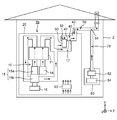
- FIG. 1 is a configuration diagram showing an example of a power generation system of the present disclosure.
- FIG. 2 is a side view of a ventilation device and a hollow article forming a ventilation path in the power generation system shown in FIG.
- FIG. 3A is a top view of the hollow article shown in FIG.
- FIG. 3B is a top view showing another example of the hollow article.
- FIG. 4 is a cross-sectional view taken along line 4-4 of the hollow article shown in FIG.
- FIG. 5 is a block diagram showing another example of the power generation system of the present disclosure.
- a ventilating device when ventilating the inside of the housing using a ventilating device, the air blown out by the ventilating device and the exhaust gas of the fuel cell unit are merged and discharged to the atmosphere Conceivable.
- the exhaust gas contains water vapor, and when the exhaust gas is cooled, condensed water is generated.
- condensed water if condensed water enters the inside of a ventilator, it may affect the durability of the ventilator. For this reason, it is desirable to prevent a liquid such as condensed water from flowing toward the upstream of the ventilation path through which the air blown out by the ventilation device flows.
- the present inventors have proposed a power generation system of the present disclosure that can prevent liquid from entering the ventilator even if the ventilation route does not have a specific structure.
- a power generation system includes a fuel cell unit, a housing, a ventilator, a ventilation path, and a discharge path.
- the fuel cell unit includes a fuel cell.
- the housing accommodates the fuel cell unit.
- the ventilation device is disposed inside the housing and blows out the air inside the housing.
- the ventilation path is disposed inside the housing, through which the air blown out from the ventilation system and the exhaust gas discharged from the fuel cell unit pass.
- the discharge path is disposed outside the housing and connected to the ventilation path, and discharges the air and the exhaust gas having passed through the ventilation path to the atmosphere.
- the air outlet of the ventilator is located above the bottom of the ventilation path adjacent to the outlet.
- the ventilation path has a projection that protrudes inward relative to a bottom surface or a surrounding wall forming a side of the ventilation path, and the outlet is a projection. Located at the tip of the unit. According to this aspect, even if the liquid flows along the wall surface around the protrusion, the liquid can be prevented from entering the ventilator.
- the outlet is horizontally separated from the boundary between the ventilation path and the discharge path. According to this aspect, even if a liquid such as rainwater falls so as to pass through the boundary between the ventilation path and the discharge path, the liquid does not pass through the outlet. Therefore, it is possible to more reliably prevent the liquid from entering the ventilator.
- the ventilation path includes a horizontal flow path through which air flows in the horizontal direction, and the horizontal flow path has a horizontally long cross section.
- the height of the horizontal flow passage can be reduced while increasing the cross-sectional area of the horizontal flow passage. Thereby, it can suppress that the flow path resistance of a ventilation path becomes high, and can suppress the height which a ventilation path occupies in the inside of a case.
- the ventilation path includes a junction where exhaust gas and air merge, and the junction is downstream of the outlet in the air flow direction. To position.
- the exhaust gases merge downstream of the outlet in the air flow direction. For this reason, the exhaust gas containing water vapor is unlikely to pass near the outlet. As a result, even if condensed water is generated from the water vapor contained in the exhaust gas, it is possible to more reliably prevent the liquid from entering the ventilator.
- the ventilation path includes a horizontal flow path through which air flows horizontally, and the junction is located in the horizontal flow path. According to this aspect, it is also possible to join the flow of the exhaust gas so as to be orthogonal to the flow of the air flowing along the horizontal direction. Therefore, the exhaust gas is likely to be diluted by air. This can enhance the safety of the power generation system.
- a ceiling of the ventilation path includes a first portion located above the outlet, a second portion contacting the junction, a first portion and a second portion And a third portion having a downward slope from the first portion to the second portion.
- the condensed water does not easily reach the outlet along the ceiling of the ventilation path. This can more reliably prevent the liquid from entering the ventilator.
- the power generation system is, in addition to the sixth aspect, a drainage formed at a boundary between the ventilation route and the discharge route and below the junction and on a bottom surface of the ventilation route or a wall connected to the bottom surface. Also have a mouth.
- the ventilation path includes a horizontal flow path through which air flows horizontally, and the outlet is located between the junction and the outlet in a direction perpendicular to the cross section of the horizontal flow path.
- a liquid such as condensed water is guided along the bottom surface of the ventilation path and near the outlet to the outlet. In this way it is possible to prevent the liquid from entering the ventilator despite the flow of the liquid upstream of the ventilation channel.
- the ventilator in addition to the first aspect, includes a backflow preventer disposed adjacent to the outlet. According to this aspect, for example, even if the exhaust gas flows toward the upstream of the ventilation path, the backflow preventer can prevent the exhaust gas from entering the ventilator. This can enhance the durability of the power generation system.
- the fuel cell unit further includes a fuel processor that generates a fuel gas to be supplied to the fuel cell.
- the fuel processor can generate fuel gas to be supplied to the fuel cell.
- the power generation system 1 a includes a fuel cell unit 10, a housing 20, a ventilator 30, a ventilation path 40, and a discharge path 50.
- the fuel cell unit 10 includes a fuel cell 11.
- the housing 20 accommodates the fuel cell unit 10.
- the ventilation device 30 is disposed inside the housing 20 and blows out the air inside the housing 20.
- the ventilation path 40 is disposed inside the housing 20.
- the air blown out from the ventilation device 30 and the exhaust gas discharged from the fuel cell unit 10 pass through the ventilation path 40.
- the discharge path 50 is disposed outside the housing 20 and connected to the ventilation path 40.
- the exhaust path 50 exhausts the air and exhaust gas having passed through the ventilation path 40 to the atmosphere.
- the ventilation device 30 may have any configuration as long as it can suck in the air inside the housing 20 and blow it out from the air outlet 32.
- the ventilation device 30 includes fans such as a propeller fan, a sirocco fan, and a turbo fan, for example.
- the hollow article 41 is made of, for example, a synthetic resin such as polypropylene. In this case, it is easy to form the hollow article 41 into a desired shape and to reduce the weight.
- the ventilation path 40 has a protrusion 44.
- the protrusion 44 protrudes inward from the wall surface around the protrusion 44, which is the bottom surface 42.
- the air outlet 32 is located at the tip of the protrusion 44. Thereby, even if a liquid such as condensed water flows along the wall surface around the projecting portion 44, the liquid is prevented from entering the ventilation device 30.
- the protrusion 44 may project inward from the wall surface around the protrusion 44 which forms the side of the ventilation path 40.
- the air outlet 32 is horizontally separated from the boundary 45 between the ventilation passage 40 and the discharge passage 50. In this case, even if a liquid such as rainwater passes through the boundary 45, the liquid can be more reliably prevented from passing through the outlet 32 and entering the ventilator 30.
- the ventilation path 40 includes a horizontal flow path 46.
- the air blown out of the ventilator 30 flows horizontally in the horizontal flow path 46.
- the horizontal flow path 46 has a horizontally long cross section.
- the cross section of the horizontal flow channel 46 means a cross section orthogonal to the flow direction of air in the horizontal flow channel 46.
- the blowout port 32 is adjacent to the first side surface 43a of the first side surface 43a and the second side surface 43b extending along the air flow direction (the positive direction of the y axis) in the horizontal flow passage 46. Do. Thereby, the dimension of the x-axis direction of the hollow article 41 can be made small, maintaining the opening area of the blower outlet 32 wide. As shown to FIG. 3B, in the hollow article 41, the blower outlet 32 may be separated from the 1st side 43a and the 2nd side 43b.
- the ventilation path 40 has a junction 48.
- the merging portion 48 the exhaust gas discharged from the fuel cell unit 10 merges with the air blown out by the ventilation device 30.
- the merging portion 48 is located downstream of the outlet 32 in the flow direction of the air blown out by the ventilation device 30. In this case, the exhaust gases merge downstream of the outlet 32 in the air flow direction. For this reason, the exhaust gas containing water vapor is unlikely to pass near the outlet 32. Thereby, it is possible to prevent the condensed water generated from the water vapor contained in the exhaust gas from entering the ventilation device 30.
- the merging portion 48 is located in the horizontal flow path 46.
- the flow of the exhaust gas joins the flow of the air flowing in the horizontal direction at a right angle, the exhaust gas is easily diluted by the air.
- Exhaust gas is led to the merging portion 48 in the horizontal flow path 46 from a direction different from the air flow direction (the positive direction of the y-axis). Exhaust gas is desirably directed to junction 48 perpendicular to the flow of air in horizontal flow path 46. Thereby, the exhaust gas is easily diluted by air.
- the hollow article 41 has the cylindrical 1st protrusion part 41a.
- the first protrusion 41 a is formed on the side surface of the hollow article 41 and protrudes outward from the surrounding wall surface. The exhaust gas is guided to the merging portion 48 through the inside of the first projecting portion 41a.
- the cross-sectional area of the ventilation path 40 at the merging portion 48 is equal to or larger than the opening area of the outlet 32. In this case, the merging of the exhaust gas and the air makes it easy to suppress the increase in the flow path resistance of the ventilation path 40.
- the ceiling 49 of the ventilation passage 40 has a first portion 49a, a second portion 49b, and a third portion 49c.
- the first portion 49 a is located above the outlet 32.
- the second portion 49 b contacts the merging portion 48.
- the third portion 49c is located between the first portion 49a and the second portion 49b and has a downward slope from the first portion 49a to the second portion 49b.
- condensed water generated from the water vapor contained in the exhaust gas may adhere to the second portion 49 b.
- Condensed water adhering to the second portion 49 b is moved away from the first portion 49 a located above the outlet 32 by the third portion 49 c of the ceiling 49 having a downward slope from the first portion 49 a to the second portion 49 b .
- the third portion 49c may have an angle perpendicular to the air flow direction.
- the hollow article 41 has a cylindrical third projecting portion 41c.
- the drainage port 60 is located at the root of the third protrusion 41 c.
- the third protrusion 41 c is formed on the bottom of the hollow article 41 and protrudes outward from the surrounding wall surface.
- the bottom surface 42 of the ventilation passage 40 slopes downward toward the outlet 60. Thereby, a liquid such as condensed water is led to the drainage port 60 along the bottom surface 42 of the ventilation path 40.
- a tank (not shown) is disposed below the drainage port 60.
- the drainage port 60 is connected to this tank via piping.
- the tank is connected to a pipe that extends to the outside of the housing 20 and forms a drainage channel.
- the liquid such as condensed water that has passed through the drain port 60 is stored in this tank, and then led to the outside of the housing 20 through the drainage channel.
- the ventilator 30 includes a backflow preventer 35.
- the backflow preventer 35 is disposed adjacent to the outlet 32.
- the backflow preventer 35 is, for example, a swing check valve, a lift check valve, or a disc check valve.
- the backflow preventer 35 can prevent the exhaust gas from entering the ventilator 30. Thereby, the durability of the power generation system 1a can be enhanced.
- the power generation system 1 a is installed inside a building 2.
- the discharge path 50 extends to the outside of the building 2.
- the interior space of the predetermined piping forms the discharge path 50.
- the inner space in the double pipe extending to the outside of the building 2 forms a part of the discharge path 50.
- the air inside the building 2 is supplied to the inside of the power generation system 1a through the outer space in the double piping.
- the internal space of piping other than double piping may be the discharge path 50.
- the double piping may be configured such that the air outside the building 2 is supplied to the inside of the power generation system 1a through the outer space of the double piping.
- the power generation system 1 a further includes a fuel gas supplier 12 and an oxidant gas supplier 14.
- the fuel gas supplier 12 sends the fuel gas to the anode of the fuel cell 11 from a fuel gas supply source (not shown).
- the fuel gas contains hydrogen gas.
- the oxidant gas feeder 14 sends an oxidant gas such as air containing oxygen to the cathode of the fuel cell 11.
- the fuel gas supplier 12 and the oxidant gas supplier 14 are a pump and a blower, respectively.
- the fuel gas supplied to the anode and the oxidant gas supplied to the cathode react to generate electricity and heat.
- the electricity generated by the fuel cell 11 is supplied to a power load outside the housing 20.
- the heat generated by the fuel cell 11 is recovered by a heat medium such as cooling water and used, for example, to heat water.
- the fuel cell 11 is, for example, a polymer electrolyte fuel cell or a solid oxide fuel cell.
- the exhaust gas discharged from the fuel cell unit 10 is, for example, an anode off gas and a cathode off gas.
- the anode off gas contains unreacted fuel gas and is discharged from the anode of the fuel cell 11.
- the cathode off gas contains unreacted oxidant gas and is discharged from the cathode of the fuel cell 11.
- the power generation system 1 a further includes a flow path 17.
- the flow path 17 connects the vent path 40 with the outlet of the anode off gas of the anode of the fuel cell 11 and the outlet of the cathode off gas of the cathode of the fuel cell 11.
- a space inside the first protrusion 41 a forms an end of the flow path 17.
- the anode off gas and the cathode off gas are led to the ventilation path 40 through the flow path 17.
- the reaction between the fuel gas and the oxidant gas in the fuel cell 11 generates water vapor.
- the exhaust gas also contains water vapor gas.
- the fuel supplied to the combustor 82 is, for example, a combustible gas such as natural gas or a liquid fuel such as kerosene.
- the air supplier 84 is, for example, a fan or a blower.
- the combustion device 80 further comprises an exhaust gas passage 70.
- the exhaust gas passage 70 connects the exhaust gas passage in the combustor 82 with the exhaust gas passage.
- the discharge path 50 has a merging portion 55 inside the building 2. In the merging portion 55, the air and the exhaust gas discharged from the housing 20 merge with the combustion exhaust gas discharged from the combustor 82. These gases pass through the discharge path 50 and are discharged to the atmosphere.
- the ventilator 30 comprises a backflow preventer 35.
- the flue gas generated by the combustor 82 flows upstream of the ventilation path 40, the flue gas can be prevented from entering the inside of the ventilator 30.
- the durability of the power generation system 1a can be enhanced.
- the power generation system 1a further includes a controller 90.
- the controller 90 is, for example, a digital computer in which a program for operating the power generation system 1a is executably stored.
- the controller 90 obtains information indicating measurement results by measurement devices such as a temperature sensor and a flow meter of the power generation system 1a, and also a fuel gas supply device 12, an oxidant gas supply device 14, a ventilator 30, a fan, a blower, Send control signals to pumps, heaters, valves, etc.
- the power generation system 1a can be changed from various viewpoints.
- the power generation system 1a may be changed to the power generation system 1b shown in FIG.
- the fuel cell unit 10 includes a fuel processor 15.
- the fuel processor 15 generates a fuel gas to be supplied to the fuel cell 11.
- the fuel processor 15 includes a reformer 15a and a combustor 15b.
- the reformer 15a generates hydrogen by a reforming reaction such as a steam reforming reaction (CH4 + H2O ⁇ CO + 3H2).
- the reformer 15a contains a reforming catalyst for advancing the reforming reaction.
- the reformer 15a also contains a catalyst for removing carbon monoxide.
- Catalysts for removing carbon monoxide include CO shift catalyst and CO selective oxidation removal catalyst.
- hydrocarbon gas such as city gas and LP gas (liquefied petroleum gas) is supplied as a source gas to the reformer 15a.
- a fuel gas containing hydrogen generated by the reformer 15 a is supplied to the fuel cell 11.
- the combustor 15 b is connected to the anode off gas outlet of the fuel cell 11.
- the anode off gas is supplied to the combustor 15b as a combustion gas.
- the power generation system 1 b includes an air supplier 16, and the air supplier 16 supplies air to the combustor 15 b.
- the air supplier 16 is, for example, a pump or a blower.
- the combustor 15b heat is generated by the combustion of the anode off gas and air to generate a flue gas.
- the heat generated by the combustor 15b heats the reformer 15a and the reforming reaction proceeds.
- the flow path 17 is connected to the outlet of the combustion exhaust gas of the combustor 15b. Therefore, the flue gas generated by the combustor 15 b is led to the ventilation path 40 as the exhaust gas together with the cathode off gas through the flow path 17. Not only the anode off gas but also the cathode off gas may be supplied to the combustor 15b.
- the power generation system is applicable to the field of fuel cells.
Landscapes
- Life Sciences & Earth Sciences (AREA)
- Engineering & Computer Science (AREA)
- Manufacturing & Machinery (AREA)
- Sustainable Development (AREA)
- Sustainable Energy (AREA)
- Chemical & Material Sciences (AREA)
- Chemical Kinetics & Catalysis (AREA)
- Electrochemistry (AREA)
- General Chemical & Material Sciences (AREA)
- Fuel Cell (AREA)
Abstract
Description
2 建物
10 燃料電池ユニット
11 燃料電池
12 燃料ガス供給器
14 酸化剤ガス供給器
15 燃料処理器
15a 改質器
15b、82 燃焼器
16、84 空気供給器
17 流路
20 筐体
30 換気装置
32 吹出口
35 逆流防止器
40 換気経路
41 中空品
41a 第一突出部
41b 第二突出部
41c 第三突出部
42 底面
43a 第一側面
43b 第二側面
44 突出部
45 境界
46 水平流路
48、55 合流部
49 天井
49a 第一部分
49b 第二部分
49c 第三部分
50 排出経路
60 排水口
70 排ガス経路
80 燃焼装置
90 制御器
Claims (12)
- 燃料電池を含む燃料電池ユニットと、
前記燃料電池ユニットを収容する筐体と
前記筐体の内部に配置され、前記筐体の内部の空気を吹き出す換気装置と、
前記筐体の内部に配置され、前記換気装置から吹き出された前記空気および前記燃料電池ユニットから排出された排出ガスが通過する換気経路と、
前記筐体の外部に配置されて前記換気経路に連なり、前記換気経路を通過した前記空気および前記排出ガスを大気に排出させる排出経路と、を備え、
前記換気装置における前記空気の吹出口は、前記吹出口に隣接する前記換気経路の底面よりも上方に位置する、
発電システム。 - 前記換気経路が、前記底面または前記換気経路の側面をなす周囲の壁面よりも内側に突出した突出部を有し、
前記吹出口が、前記突出部の先端に位置する、請求項1に記載の発電システム。 - 前記吹出口が上向きに開口する、請求項1に記載の発電システム。
- 前記吹出口が、前記換気経路と前記排出経路との境界から水平方向に離れている、請求項1に記載の発電システム。
- 前記換気経路が、前記空気が水平方向に流れる水平流路を含み、
前記水平流路が、横長の断面を有する、
請求項1に記載の発電システム。 - 前記換気経路が、前記排出ガスと前記空気とが合流する合流部を有し、
前記合流部が、前記空気の流れ方向において前記吹出口の下流に位置する、請求項1に記載の発電システム。 - 前記換気経路が、前記空気が水平方向に流れる水平流路を含み、
前記合流部が、前記水平流路に位置する、請求項6に記載の発電システム。 - 前記換気経路の天井が、前記吹出口の上方に位置する第一部分と、前記合流部に接する第二部分と、前記第一部分と前記第二部分との間に位置し、前記第一部分から前記第二部分に向かって下向きの傾斜を有する第三部分とを有する、請求項7に記載の発電システム。
- 前記換気経路と前記排出経路との境界および前記合流部の下方に位置するとともに、前記換気経路の底面または前記底面に連なる壁面に形成された排水口をさらに備え、
前記換気経路は、前記空気が水平方向に流れる水平流路を含み、
前記吹出口は、前記水平流路の断面に垂直な方向において前記合流部と前記排水口との間に位置する、
請求項6に記載の発電システム。 - 前記合流部における前記換気経路の断面積が、前記吹出口の開口面積以上である、請求項1に記載の発電システム。
- 前記換気装置が、前記吹出口に隣接して配置された逆流防止器を備える、請求項1に記載の発電システム。
- 前記燃料電池ユニットが、前記燃料電池に供給されるべき燃料ガスを生成する燃料処理器をさらに含む、請求項1に記載の発電システム。
Priority Applications (2)
| Application Number | Priority Date | Filing Date | Title |
|---|---|---|---|
| JP2019567835A JP7050235B2 (ja) | 2018-01-26 | 2018-08-31 | 発電システム |
| EP18902856.6A EP3745514B1 (en) | 2018-01-26 | 2018-08-31 | Power generation system |
Applications Claiming Priority (2)
| Application Number | Priority Date | Filing Date | Title |
|---|---|---|---|
| JP2018-011260 | 2018-01-26 | ||
| JP2018011260 | 2018-01-26 |
Publications (1)
| Publication Number | Publication Date |
|---|---|
| WO2019146146A1 true WO2019146146A1 (ja) | 2019-08-01 |
Family
ID=67395598
Family Applications (1)
| Application Number | Title | Priority Date | Filing Date |
|---|---|---|---|
| PCT/JP2018/032305 Ceased WO2019146146A1 (ja) | 2018-01-26 | 2018-08-31 | 発電システム |
Country Status (3)
| Country | Link |
|---|---|
| EP (1) | EP3745514B1 (ja) |
| JP (1) | JP7050235B2 (ja) |
| WO (1) | WO2019146146A1 (ja) |
Cited By (2)
| Publication number | Priority date | Publication date | Assignee | Title |
|---|---|---|---|---|
| JPWO2022054265A1 (ja) * | 2020-09-14 | 2022-03-17 | ||
| JP2023058387A (ja) * | 2021-10-13 | 2023-04-25 | 株式会社東芝 | 燃料電池システム、及び排出方法 |
Families Citing this family (1)
| Publication number | Priority date | Publication date | Assignee | Title |
|---|---|---|---|---|
| CN115036617B (zh) * | 2022-07-29 | 2024-12-03 | 南通中集元能集成科技有限公司 | 储能集装箱 |
Citations (4)
| Publication number | Priority date | Publication date | Assignee | Title |
|---|---|---|---|---|
| JP2006253020A (ja) * | 2005-03-11 | 2006-09-21 | Toshiba Fuel Cell Power Systems Corp | 燃料電池発電装置及び吸排気装置 |
| JP2008210631A (ja) | 2007-02-26 | 2008-09-11 | Kyocera Corp | 発電装置 |
| WO2012153482A1 (ja) * | 2011-05-06 | 2012-11-15 | パナソニック株式会社 | 発電システム及びその運転方法 |
| JP2015113987A (ja) | 2013-12-09 | 2015-06-22 | パナソニックIpマネジメント株式会社 | 発電システム |
Family Cites Families (1)
| Publication number | Priority date | Publication date | Assignee | Title |
|---|---|---|---|---|
| JP6389658B2 (ja) * | 2014-06-30 | 2018-09-12 | アイシン精機株式会社 | 燃料電池システム |
-
2018
- 2018-08-31 JP JP2019567835A patent/JP7050235B2/ja active Active
- 2018-08-31 WO PCT/JP2018/032305 patent/WO2019146146A1/ja not_active Ceased
- 2018-08-31 EP EP18902856.6A patent/EP3745514B1/en active Active
Patent Citations (4)
| Publication number | Priority date | Publication date | Assignee | Title |
|---|---|---|---|---|
| JP2006253020A (ja) * | 2005-03-11 | 2006-09-21 | Toshiba Fuel Cell Power Systems Corp | 燃料電池発電装置及び吸排気装置 |
| JP2008210631A (ja) | 2007-02-26 | 2008-09-11 | Kyocera Corp | 発電装置 |
| WO2012153482A1 (ja) * | 2011-05-06 | 2012-11-15 | パナソニック株式会社 | 発電システム及びその運転方法 |
| JP2015113987A (ja) | 2013-12-09 | 2015-06-22 | パナソニックIpマネジメント株式会社 | 発電システム |
Non-Patent Citations (1)
| Title |
|---|
| See also references of EP3745514A4 |
Cited By (3)
| Publication number | Priority date | Publication date | Assignee | Title |
|---|---|---|---|---|
| JPWO2022054265A1 (ja) * | 2020-09-14 | 2022-03-17 | ||
| JP7487784B2 (ja) | 2020-09-14 | 2024-05-21 | 三菱電機株式会社 | 送風機制御システム |
| JP2023058387A (ja) * | 2021-10-13 | 2023-04-25 | 株式会社東芝 | 燃料電池システム、及び排出方法 |
Also Published As
| Publication number | Publication date |
|---|---|
| JPWO2019146146A1 (ja) | 2021-01-28 |
| JP7050235B2 (ja) | 2022-04-08 |
| EP3745514A4 (en) | 2021-03-17 |
| EP3745514B1 (en) | 2025-04-09 |
| EP3745514A1 (en) | 2020-12-02 |
Similar Documents
| Publication | Publication Date | Title |
|---|---|---|
| JP7050235B2 (ja) | 発電システム | |
| JP5914862B2 (ja) | 燃料電池システム | |
| KR101365326B1 (ko) | 발전 시스템 및 그 운전 방법 | |
| WO2007129602A1 (ja) | 燃料電池システム | |
| JP5280588B2 (ja) | 発電システム及びその運転方法 | |
| US9214685B2 (en) | Fuel cell system | |
| JP2009277612A (ja) | 排気口カバー及び燃料電池ユニット | |
| JP2013161754A (ja) | 燃料電池システム | |
| KR20130133806A (ko) | 연료 전지 시스템 | |
| JP7029630B2 (ja) | 燃料電池システム | |
| JP2011018534A (ja) | 燃料電池システム | |
| JP4383481B2 (ja) | 燃料電池システム | |
| JP7050233B2 (ja) | 燃料電池システム | |
| JP2007048704A (ja) | 燃料電池装置 | |
| JP7113229B2 (ja) | 燃料電池システム | |
| JP2014191965A (ja) | 燃料電池システム | |
| JP2015113987A (ja) | 発電システム | |
| JP2014007001A (ja) | 燃料電池システム | |
| JP6650592B2 (ja) | 燃料電池システム | |
| WO2010122700A1 (ja) | 燃料電池システム | |
| JP6229145B2 (ja) | 燃料電池システム | |
| JP4556689B2 (ja) | 水素生成器 | |
| JP6820497B2 (ja) | 燃料電池システム | |
| JP2019129049A (ja) | 燃料電池システム | |
| JP6023983B2 (ja) | 燃料電池システム |
Legal Events
| Date | Code | Title | Description |
|---|---|---|---|
| 121 | Ep: the epo has been informed by wipo that ep was designated in this application |
Ref document number: 18902856 Country of ref document: EP Kind code of ref document: A1 |
|
| ENP | Entry into the national phase |
Ref document number: 2019567835 Country of ref document: JP Kind code of ref document: A |
|
| NENP | Non-entry into the national phase |
Ref country code: DE |
|
| ENP | Entry into the national phase |
Ref document number: 2018902856 Country of ref document: EP Effective date: 20200826 |
|
| WWG | Wipo information: grant in national office |
Ref document number: 2018902856 Country of ref document: EP |