WO2019146637A1 - 誘導型回転検出装置 - Google Patents
誘導型回転検出装置 Download PDFInfo
- Publication number
- WO2019146637A1 WO2019146637A1 PCT/JP2019/002073 JP2019002073W WO2019146637A1 WO 2019146637 A1 WO2019146637 A1 WO 2019146637A1 JP 2019002073 W JP2019002073 W JP 2019002073W WO 2019146637 A1 WO2019146637 A1 WO 2019146637A1
- Authority
- WO
- WIPO (PCT)
- Prior art keywords
- rotating body
- rotation
- detection device
- secondary coil
- pattern
- Prior art date
- Legal status (The legal status is an assumption and is not a legal conclusion. Google has not performed a legal analysis and makes no representation as to the accuracy of the status listed.)
- Ceased
Links
Images



Classifications
-
- G—PHYSICS
- G01—MEASURING; TESTING
- G01B—MEASURING LENGTH, THICKNESS OR SIMILAR LINEAR DIMENSIONS; MEASURING ANGLES; MEASURING AREAS; MEASURING IRREGULARITIES OF SURFACES OR CONTOURS
- G01B7/00—Measuring arrangements characterised by the use of electric or magnetic techniques
- G01B7/30—Measuring arrangements characterised by the use of electric or magnetic techniques for measuring angles or tapers; for testing the alignment of axes
-
- G—PHYSICS
- G01—MEASURING; TESTING
- G01D—MEASURING NOT SPECIALLY ADAPTED FOR A SPECIFIC VARIABLE; ARRANGEMENTS FOR MEASURING TWO OR MORE VARIABLES NOT COVERED IN A SINGLE OTHER SUBCLASS; TARIFF METERING APPARATUS; MEASURING OR TESTING NOT OTHERWISE PROVIDED FOR
- G01D5/00—Mechanical means for transferring the output of a sensing member; Means for converting the output of a sensing member to another variable where the form or nature of the sensing member does not constrain the means for converting; Transducers not specially adapted for a specific variable
- G01D5/12—Mechanical means for transferring the output of a sensing member; Means for converting the output of a sensing member to another variable where the form or nature of the sensing member does not constrain the means for converting; Transducers not specially adapted for a specific variable using electric or magnetic means
- G01D5/14—Mechanical means for transferring the output of a sensing member; Means for converting the output of a sensing member to another variable where the form or nature of the sensing member does not constrain the means for converting; Transducers not specially adapted for a specific variable using electric or magnetic means influencing the magnitude of a current or voltage
- G01D5/20—Mechanical means for transferring the output of a sensing member; Means for converting the output of a sensing member to another variable where the form or nature of the sensing member does not constrain the means for converting; Transducers not specially adapted for a specific variable using electric or magnetic means influencing the magnitude of a current or voltage by varying inductance, e.g. by a movable armature
- G01D5/2006—Mechanical means for transferring the output of a sensing member; Means for converting the output of a sensing member to another variable where the form or nature of the sensing member does not constrain the means for converting; Transducers not specially adapted for a specific variable using electric or magnetic means influencing the magnitude of a current or voltage by varying inductance, e.g. by a movable armature by influencing the self-induction of one or more coils
-
- B—PERFORMING OPERATIONS; TRANSPORTING
- B62—LAND VEHICLES FOR TRAVELLING OTHERWISE THAN ON RAILS
- B62M—RIDER PROPULSION OF WHEELED VEHICLES OR SLEDGES; POWERED PROPULSION OF SLEDGES OR SINGLE-TRACK CYCLES; TRANSMISSIONS SPECIALLY ADAPTED FOR SUCH VEHICLES
- B62M6/00—Rider propulsion of wheeled vehicles with additional source of power, e.g. combustion engine or electric motor
- B62M6/40—Rider propelled cycles with auxiliary electric motor
- B62M6/45—Control or actuating devices therefor
- B62M6/50—Control or actuating devices therefor characterised by detectors or sensors, or arrangement thereof
-
- B—PERFORMING OPERATIONS; TRANSPORTING
- B62—LAND VEHICLES FOR TRAVELLING OTHERWISE THAN ON RAILS
- B62M—RIDER PROPULSION OF WHEELED VEHICLES OR SLEDGES; POWERED PROPULSION OF SLEDGES OR SINGLE-TRACK CYCLES; TRANSMISSIONS SPECIALLY ADAPTED FOR SUCH VEHICLES
- B62M6/00—Rider propulsion of wheeled vehicles with additional source of power, e.g. combustion engine or electric motor
- B62M6/40—Rider propelled cycles with auxiliary electric motor
- B62M6/55—Rider propelled cycles with auxiliary electric motor power-driven at crank shafts parts
-
- G—PHYSICS
- G01—MEASURING; TESTING
- G01B—MEASURING LENGTH, THICKNESS OR SIMILAR LINEAR DIMENSIONS; MEASURING ANGLES; MEASURING AREAS; MEASURING IRREGULARITIES OF SURFACES OR CONTOURS
- G01B7/00—Measuring arrangements characterised by the use of electric or magnetic techniques
- G01B7/003—Measuring arrangements characterised by the use of electric or magnetic techniques for measuring position, not involving coordinate determination
-
- G—PHYSICS
- G01—MEASURING; TESTING
- G01D—MEASURING NOT SPECIALLY ADAPTED FOR A SPECIFIC VARIABLE; ARRANGEMENTS FOR MEASURING TWO OR MORE VARIABLES NOT COVERED IN A SINGLE OTHER SUBCLASS; TARIFF METERING APPARATUS; MEASURING OR TESTING NOT OTHERWISE PROVIDED FOR
- G01D5/00—Mechanical means for transferring the output of a sensing member; Means for converting the output of a sensing member to another variable where the form or nature of the sensing member does not constrain the means for converting; Transducers not specially adapted for a specific variable
- G01D5/12—Mechanical means for transferring the output of a sensing member; Means for converting the output of a sensing member to another variable where the form or nature of the sensing member does not constrain the means for converting; Transducers not specially adapted for a specific variable using electric or magnetic means
- G01D5/14—Mechanical means for transferring the output of a sensing member; Means for converting the output of a sensing member to another variable where the form or nature of the sensing member does not constrain the means for converting; Transducers not specially adapted for a specific variable using electric or magnetic means influencing the magnitude of a current or voltage
- G01D5/20—Mechanical means for transferring the output of a sensing member; Means for converting the output of a sensing member to another variable where the form or nature of the sensing member does not constrain the means for converting; Transducers not specially adapted for a specific variable using electric or magnetic means influencing the magnitude of a current or voltage by varying inductance, e.g. by a movable armature
- G01D5/204—Mechanical means for transferring the output of a sensing member; Means for converting the output of a sensing member to another variable where the form or nature of the sensing member does not constrain the means for converting; Transducers not specially adapted for a specific variable using electric or magnetic means influencing the magnitude of a current or voltage by varying inductance, e.g. by a movable armature by influencing the mutual induction between two or more coils
-
- G—PHYSICS
- G01—MEASURING; TESTING
- G01L—MEASURING FORCE, STRESS, TORQUE, WORK, MECHANICAL POWER, MECHANICAL EFFICIENCY, OR FLUID PRESSURE
- G01L3/00—Measuring torque, work, mechanical power, or mechanical efficiency, in general
- G01L3/02—Rotary-transmission dynamometers
- G01L3/04—Rotary-transmission dynamometers wherein the torque-transmitting element comprises a torsionally-flexible shaft
- G01L3/10—Rotary-transmission dynamometers wherein the torque-transmitting element comprises a torsionally-flexible shaft involving electric or magnetic means for indicating
- G01L3/101—Rotary-transmission dynamometers wherein the torque-transmitting element comprises a torsionally-flexible shaft involving electric or magnetic means for indicating involving magnetic or electromagnetic means
- G01L3/105—Rotary-transmission dynamometers wherein the torque-transmitting element comprises a torsionally-flexible shaft involving electric or magnetic means for indicating involving magnetic or electromagnetic means involving inductive means
-
- G—PHYSICS
- G01—MEASURING; TESTING
- G01P—MEASURING LINEAR OR ANGULAR SPEED, ACCELERATION, DECELERATION, OR SHOCK; INDICATING PRESENCE, ABSENCE, OR DIRECTION, OF MOVEMENT
- G01P3/00—Measuring linear or angular speed; Measuring differences of linear or angular speeds
- G01P3/42—Devices characterised by the use of electric or magnetic means
- G01P3/44—Devices characterised by the use of electric or magnetic means for measuring angular speed
- G01P3/48—Devices characterised by the use of electric or magnetic means for measuring angular speed by measuring frequency of generated current or voltage
- G01P3/481—Devices characterised by the use of electric or magnetic means for measuring angular speed by measuring frequency of generated current or voltage of pulse signals
- G01P3/488—Devices characterised by the use of electric or magnetic means for measuring angular speed by measuring frequency of generated current or voltage of pulse signals delivered by variable reluctance detectors
Definitions
- the present invention relates to an inductive rotation detection device, and further to a combined detection device for detecting the rotation of a rotating shaft in combination with a torque sensor for detecting the torque of the rotating shaft.
- the present invention is applicable to rotation detection of a shaft or rotation detection of a steering shaft of an automobile.
- the magnetic response member (or magnetic coupling member) magnetically coupled to the coil and displaced according to the detection target position is a metal material made of a ferromagnetic material such as iron or a good conductor such as copper It is used and shaped to change its area or volume.
- Patent Documents 7 to 9 show an example thereof. What is shown by patent document 7 or 8 provides a steering shaft as an induction-type torque sensor and an induction-type rotational position detection apparatus as an independent structure, respectively. According to Patent Document 9, while providing an induction type torque sensor on a steering shaft, a rotation angle detection means is provided via a transmission gear mechanism. Various combinations of a torque sensor and a rotation detection device in a pedal crankshaft of a motor-assisted bicycle are also known. The following Patent Documents 10 to 12 show an example thereof.
- the coils disposed on flat substrates as shown in Patent Documents 1 to 6 are suitable for linear position detection devices, but not very suitable for rotational position detection devices. Further, in the configuration in which the area or volume of the magnetic response member (or magnetic coupling member) changes in accordance with the detection target position, it is difficult to miniaturize the configuration of the movable portion.
- the present invention has been made in view of the above-mentioned points, and an object of the present invention is to provide a rotation detection device having a simple structure suitable for promoting miniaturization in a rotation detection device, and further, It is an object of the present invention to provide a combined type detection device that detects the rotation of a rotating shaft in combination with a torque sensor in a simplified configuration.
- the rotation detecting device is a magnetic response which is disposed on the rotating body along the circumference of the rotating body so as to rotate with the rotating body, and has a linear pattern periodically displaced in the rotation axis direction.
- a stator disposed noncontactingly around the rotating body, the stator including a secondary coil forming a loop pattern of a plurality of cycles along a circumference of the rotating body;
- the secondary coil is placed in an alternating magnetic field, and an inductive output AC signal corresponding to the relative position of the linear pattern of the magnetic response member depending on the rotational position of the rotating body and the loop pattern of the secondary coil is It is made to output from a secondary coil.
- the magnetic response member disposed on the rotating body has a linear pattern periodically displaced in the rotation axis direction, so the structure is simple and the miniaturization of the detection device is promoted. It is suitable for In addition, in the coil configuration in the stator, the secondary coil is configured to form a loop pattern of multiple cycles along the circumference of the rotating body, so the device is compactly installed along the circumference of the rotating body It is suitable for In this way, it is possible to provide a rotation detection device having a simple structure suitable for promoting miniaturization in the rotation detection device.
- the rotating body may be a rotating shaft itself provided in a machine or device to be subjected to rotation detection. Therefore, a dedicated rotor component in the rotation detection device can be omitted or simplified, which further contributes to the miniaturization of the entire detection device.
- the stator may include a primary coil for generating the alternating magnetic field.
- the primary coil may consist of a cylindrical coil wound around the rotating body, which allows a simple configuration to generate a necessary and sufficient alternating magnetic field around the rotating body.
- the stator does not include the primary coil, and the rotation detection device is disposed in proximity to other detection devices including the primary coil for generating the alternating magnetic field. May be In that case, the secondary coil included in the stator is placed in an alternating magnetic field leaking from the primary coil of the other detection device.
- the combination detection device may be configured by combining this rotation detection device with a torque sensor that detects a twisting torque generated in a rotatable shaft.
- the torque sensor may be configured to include at least a primary coil for generating an alternating magnetic field, whereby the torque sensor can function as the other detection device.
- the combined detection device according to the invention is a torque sensor that detects a twisting torque generated in a rotatable shaft (rotating body), and the torque includes at least a primary coil for generating an alternating magnetic field.
- a rotation detection device for detecting the rotation of the shaft, the rotation detection device being disposed on the rotating body along the circumference of the rotating body that rotates with the shaft, and the rotation axis direction
- a magnetic response member consisting of a linear pattern that is periodically displaced, and a stator non-contactingly arranged around the rotating body, wherein a loop pattern of multiple cycles is formed along the circumference of the rotating body And the stator including the secondary coil to be formed, the secondary coil being placed in the alternating magnetic field leaking from the primary coil of the torque sensor, the rotational position of the rotating body And outputting from the secondary coil of the rotation detection device an inductive output AC signal according to the relative position of the pattern of the linear shape of the magnetic response member and the loop pattern of the secondary coil.
- the rotation detection device does not have a dedicated primary coil, and the stator only needs to include the secondary coil, so the structure of the rotation detection device is simplified. Can.
- the magnetic response member disposed on the rotating body is formed of a linear pattern periodically displaced in the rotation axis direction, the structure is simple and the rotation detection device can be miniaturized. Is suitable.
- the secondary coil is configured to form a loop pattern of multiple cycles along the circumference of the rotating body, so the device is compactly installed along the circumference of the rotating body It is suitable for Thus, it is possible to provide a combined type detection device having a simple structure suitable for promoting miniaturization. Furthermore, since the transmission gear mechanism is not required, the decrease in control performance due to the gear backlash does not occur.
- (A) is a schematic perspective view which shows the external appearance of the rotation detection apparatus based on one Example of this invention
- (b) is a schematic perspective view which decomposes
- (A) is an expanded view of the loop pattern of the secondary coil
- (b) is an expanded view of the pattern of the magnetic response member
- (c) to (e) are rotations different from (b) The figure which expands and illustrates the pattern of the magnetic response member when it is in the position
- (f) shows an example of the level change over one rotation (one circumference) of the induction output alternating current signal of the secondary coil
- (g) The figure which shows another example of the level change over 1 rotation (1 circumference) of the induction output alternating current signal of the secondary coil
- (h) is the level over 1 rotation (1 circumference) of the induction output alternating current signal of the secondary coil
- (A) is a diagram showing an example of a circuit for obtaining data indicating the rotational position based on the induced output alternating current signal of the secondary coil
- (b) is data showing the rotational speed based on the induced output alternating current signal for the secondary coil
- the expanded view of the loop pattern of each secondary coil in the Example which piles up two secondary coils and arrange
- the outline appearance perspective view showing the example constituted as a compound type detecting device by combining the rotation detecting device concerning the present invention with another sensor which has an alternating current magnetic field generating function.
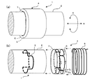
- FIG. 1 (a) is a schematic perspective view showing the appearance of a rotation detection device 1 according to an embodiment of the present invention, and (b) is a schematic perspective view showing the main parts of the rotation detection device 1 in an exploded manner.
- the rotation detecting device 1 detects the rotational position of the rotating body 2, and a magnetic response member 3 disposed on the rotating body 2 along the circumference of the rotating body 2 so as to rotate with the rotating body 2.
- a stator 4 disposed non-contactingly around the rotating body 2.
- the arrow R indicates the rotation direction of the rotating body 2
- the arrow A indicates the rotation axis direction.
- the magnetic response member 3 has a linear pattern which is periodically displaced in the rotational direction R and the rotational axis direction A, and is made of a ferromagnetic material such as iron or ferrite or a good conductor material such as copper or aluminum It consists of
- a good conductor material may be used as the magnetic response member 3.
- a magnetic material may be used as the magnetic response member 3.
- the pattern of the magnetic response member 3 can be formed directly on the circumferential surface of the rotating body 2 by an appropriate processing technique such as plating or printing or printing.
- the pattern of the magnetic response member 3 may be formed on an appropriate film made of a nonmagnetic response material, and such a film is attached to the circumferential surface of the rotating body 2 through an adhesive. By attaching, the pattern of the magnetic response member 3 can be arranged on the rotating body 2.
- the rotating body 2 is not a dedicated part of the rotation detecting device 1 but a rotating shaft itself provided in a machine or a structure or device or equipment to which the rotation detecting device 1 is applied (that is, a rotation detecting target). , That is, the rotating shaft that is the target of rotation detection. Therefore, a dedicated rotor component in the rotation detection device 1 can be omitted or simplified, which contributes to the miniaturization of the entire detection device.
- the stator 4 includes a primary coil 5 wound around the rotating body 2 and a secondary coil 6 forming a loop pattern of multiple cycles along the circumference of the rotating body 2.
- the secondary coil 6 can be configured by printed wiring of a predetermined loop pattern consisting of lead wires (conductors) on a ring-shaped insulating substrate 7 having a circumferential surface. That is, the loop pattern of the secondary coil 6 is formed on the circumferential surface of the substrate 7 which curves along the circumference of the rotating body 2.
- the primary coil 5 may consist of a cylindrical coil as is well known.
- the coil assembly of the stator 4 is configured by arranging the ring-shaped substrate 7 provided with the secondary coil 6 inside the primary coil 5 consisting of a cylindrical coil.
- the coil assembly of the stator 4 is fitted to the rotating body 2 and is fixed in a state where a portion of the magnetic response member 3 disposed on the rotating body 2 is inserted into the coil assembly.
- an alternating current signal (eg, sin ⁇ t) of a constant frequency is applied to the input terminal of the primary coil 5 to form an alternating magnetic field in the coil assembly.
- the rotation detecting device 1 installed at a predetermined position of the rotating body 2, when the rotating body 2 rotates, the pattern of the magnetic response member 3 is relative to the coil assembly of the stator 4 according to the rotating position.
- the degree of magnetic coupling between the primary coil 5 and the secondary coil 6 changes, and an output signal corresponding to the rotational position is obtained from the output terminal of the secondary coil 6.
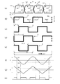
- FIG. 2A is a diagram illustrating a developed loop pattern of the secondary coil 6 disposed on the ring-shaped substrate 7.
- the secondary coil 6 forms a loop pattern of a plurality of cycles over one circumference of the ring-shaped substrate 7.
- the secondary coil 6 consists of a series of lead wires (conductors) connected between two output terminals O 1 and O 2 as a whole, and the lead wires meander in a predetermined pattern while the ring-shaped substrate
- Four loop areas L1, L2, L3, and L4 are formed by tracing back and forth (rounding back and forth) a stroke of one circumference of seven.
- the length (width) of each loop area L1, L2, L3, L4 in the rotational direction R is approximately 1 ⁇ 4 of the circumference.
- each one loop area L1, L2, L3, L4 includes upper lines up1, up2, up3, up4 and lower lines dn1, dn2, dn3, dn4, and each upper line up1 , Up2, up3, up4 are connected to lower lines dn1, dn2, dn3, dn4 of adjacent loop areas, and lower lines dn1, dn2, dn3, dn4 are connected to upper lines up1, up2, up3, up4 of adjacent loop areas Connect.
- each loop area L1, L2, L3, L4 the direction of the current flowing through the upper and lower opposing lead wires (that is, the upper line and the lower line) at a certain moment is, as exemplified by arrows in the figure, The directions are opposite to each other. It should be noted that the directions of the currents exemplified by the arrows in the drawing are the same when viewed from between the output terminals O 1 and O 2 .
- the secondary coil 6 forms a loop pattern in which the secondary coil 6 meanders in a substantially rectangular shape.
- each loop area L1, L2, L3, L4 the upper lines up1, up2, up3, up4 extend substantially linearly at the upper side of the area, and the lower lines dn1, dn2, dn3, dn4 are lower sides of the area Extends generally linearly.
- each loop area L1, L2, L3, L4 of the secondary coil 6 the direction of the current induced according to the alternating magnetic field from the primary coil 5 is the upper line up1, up2, up3, up4 and the lower line
- the same direction is used for dn1, dn2, dn3, and dn4. Therefore, for example, when the same amount of current is induced in the upper line up1 and the lower line dn1 in the loop area L1, these induced currents are canceled out, and the sum of the induced currents in the portion of the loop area L1 becomes zero. .
- FIG. 2 (b) is a diagram illustrating a developed pattern of the magnetic response members 3 arranged along the circumferential direction on the rotating body 2.
- the linear shape pattern of the magnetic response member 3 is formed of a rectangular wave pattern periodically displaced in the direction of the rotation axis A in two cycles over one circumference.
- the parts 3a and 3a 'at both ends are the same part. That is, the two-cycle change pattern of the magnetic response member 3 is connected in a ring shape.
- One cycle of the rectangular pattern of the magnetic response member 3 includes upper side portions 3up1 and 3up2 linearly extending in the rotational direction R, and lower side portions 3dn1 and 3dn2 linearly extending in the rotational direction R.
- the upper side portions 3up1 and 3up2 and the lower side portions 3dn1 and 3dn2 are offset with respect to both the rotational direction R and the axial direction A.
- the length (width) of the rotational direction R of each of the upper side portions 3up1 and 3up2 and the lower side portions 3dn1 and 3dn2 is 1/4 of the circumference.
- the upper side portion 3up1 of the pattern of the magnetic response member 3 substantially matches the loop area L1
- the lower side portion 3dn1 substantially matches the loop area L2
- the upper side portion 3up2 is a loop A state in which the area L3 substantially matches and the lower side portion 3dn2 substantially matches the loop area L4 is referred to as an in-phase state for convenience.
- the loop area L1 As for the loop area L1, when the upper side portion 3up1 of the magnetic response member 3 overlaps the entire area of the upper line up1, the maximum induced current flows in the upper line up1, while the magnetic response in the lower line dn1 Since the members 3 do not overlap, the induced current of the lower line dn1 is zero. Therefore, the induced current of the upper line up1 flows without subtraction.
- the lower side portion 3dn1 of the magnetic response member 3 overlaps the entire area of the lower line dn2, so that the maximum induced current flows in the lower line dn2, while the magnetic response member in the upper line up2 Because 3 does not overlap, the induced current of the upper line up2 is zero.
- the induced current of the lower line dn2 flows without subtraction and is added in phase with the induced current of the upper line up1.
- the loop area L3 operates in the same manner as the loop area L1
- the loop area L4 operates in the same manner as the loop area L2. In this state, it can be said that the degree of magnetic coupling in each of the loop areas L1, L2, L3 and L4 is a positive maximum value. Therefore, in this case, the maximum level derived output AC signal between the output terminals O 1, O 2 of the secondary coil 6 is generated.
- FIG. 2C is a development view showing a state in which the rotating body 2 is displaced from the position of FIG. 2B by a distance equivalent to 1 ⁇ 4 cycle of the pattern of the magnetic response member 3.
- the distance corresponding to 1 ⁇ 4 cycle of the pattern of the magnetic response member 3 can be represented by ⁇ / 2.
- the relative positional relationship of the pattern of the magnetic response member 3 shown in FIG. 2C with respect to the loop areas L1, L2, L3, L4 of the secondary coil 6 shown in FIG. It will be in the state shifted 1/4 cycle compared with the state.
- the degree of magnetic coupling in each of the loop areas L1, L2, L3 and L4 cancels out as positive and negative values, and the level of the inductive output AC signal between the output terminals O 1 and O 2 of the secondary coil 6 becomes 0. .
- FIG. 2D is a development view showing a state in which the rotating body 2 is displaced from the position of FIG. 2B by a distance equivalent to a half cycle of the pattern of the magnetic response member 3.
- the distance corresponding to a half cycle of the pattern of the magnetic response member 3 can be expressed by ⁇ .
- the relative positional relationship of the pattern of the magnetic response member 3 shown in FIG. 2D with respect to the loop areas L1, L2, L3, L4 of the secondary coil 6 shown in FIG. It will be in the state (namely, reverse phase state) shifted [1/2] cycle compared with the state.
- the degree of magnetic coupling in each of the loop areas L1, L2, L3, and L4 has a negative maximum value.
- the maximum level derived output AC signal between the output terminals O 1, O 2 of the secondary coil 6 is generated.
- the electrical phase of the maximum level inductive output AC signal generated in the positional relationship of FIG. 2 (d) is different from the electrical phase of the maximum level inductive output AC signal generated in the positional relationship of FIG. 2 (b). It is opposite phase.
- FIG. 2E is a development view showing a state in which the rotating body 2 is displaced from the position of FIG. 2B by a distance equivalent to 3 ⁇ 4 cycle of the pattern of the magnetic response member 3.
- the distance corresponding to 3 ⁇ 4 cycle of the pattern of the magnetic response member 3 can be expressed by 3 ⁇ / 2.
- the relative positional relationship of the pattern of the magnetic response member 3 shown in FIG. 2 (e) to the loop areas L1, L2, L3, L4 of the secondary coil 6 shown in FIG. It will be in the state which shifted 3/4 cycles compared with the state.
- the degree of magnetic coupling in each of the loop areas L1, L2, L3 and L4 cancels out as positive and negative values, and the level of the inductive output AC signal between the output terminals O 1 and O 2 of the secondary coil 6 becomes 0. .
- FIG. 2 (f) shows an example of the level change of the inductive output AC signal between the output terminals O 1 and O 2 of the secondary coil 6 that occurs according to the displacement over one rotation (one circumference) of the rotating body 2
- the relationship between the pattern of the magnetic response member 3 and the loop areas L1, L2, L3, L4, etc. of the secondary coil 6 is designed so that the level change of the sine function characteristic (sin ⁇ ) can be obtained.
- the angular variable ⁇ of the sine function characteristic (sin ⁇ ) is one rotation of the rotating body 2 It changes in the range of 4 ⁇ per (one circumference).
- the level changes indicative occurs a rotational position of the range of a quarter turn of the rotary member 2 in absolute value.
- Data indicating the level of the sine function characteristic (sin ⁇ ) can be obtained by rectifying an induced output AC signal (for example, sin ⁇ sin ⁇ t) between the output terminals O 1 and O 2 of the secondary coil 6, as is known.
- FIG. 2G shows another example of the level change of the inductive output AC signal between the output terminals O 1 and O 2 of the secondary coil 6 which is generated according to the displacement over one rotation (one circumference) of the rotating body 2.
- the relationship between the pattern of the magnetic response member 3 and the loop areas L1, L2, L3, L4, etc. of the secondary coil 6 is designed so that the level change of the triangular wave function characteristics can be obtained.
- the pattern of the magnetic response member 3 is arranged two cycles per one rotation (one circumference) of the rotary body 2, the angular variable ⁇ of the triangular wave function is one rotation (one circle of the rotary body 2). Changes in the range of 4 ⁇ .
- the level changes indicative occurs a rotational position of the range of a quarter turn of the rotary member 2 in absolute value.
- Data indicating the angular variable ⁇ of the triangular wave function can also be obtained by rectifying an induced output AC signal between the output terminals O 1 and O 2 of the secondary coil 6 as is known.
- the + region and the ⁇ region of the vertical axis are such that the electrical phases of the induced output AC signal between the output terminals O 1 and O 2 of the secondary coil 6 are opposite to each other
- the electrical phase of the level of the inductive output AC signal in the ⁇ region is opposite to the electrical phase of the level of the inductive output AC signal in the + region.
- the function characteristic of the level change of the induced output AC signal between the output terminals O 1, O 2 of the secondary coil 6, the sine function characteristic or a triangular wave function characteristic as shown in FIG. 2 (f) or (g) It is not limited and can be designed arbitrarily.
- an inductive output AC signal between the output terminals O 1 and O 2 of the secondary coil 6 is input to the rectifier circuit 11 Good.
- the rectifier circuit 11 rectifies the induced output AC signal to detect its amplitude level (outputs a DC voltage indicating the amplitude level).
- the rectifier circuit 11 is a circuit that obtains data indicating the rotational position of the rotating body 2 based on detection of the amplitude level of the induction output AC signal output from the secondary coil 6. Not only the rectifier circuit 11 that outputs a DC voltage indicating an amplitude level, but also a circuit that digitally detects the amplitude level of the induction output AC signal may be used.
- FIG. 3 (b) shows an example of circuit configuration for rotational speed.
- Output terminal O 1 of the secondary coil 6, an induction AC output signal between O 2 and input to the level comparator circuit 12, the output amplitude level of the induced output AC signal from a predetermined reference voltage Vr is greater than when the level comparator circuit 12 Produce a voltage.
- This reference voltage Vr is appropriately set smaller than the maximum level of the induced output AC signal generated in the positional relationship as shown in FIGS. 2 (b) and 2 (d) as exemplified in FIGS. 2 (f) and 2 (g). It is a value.
- the output voltage of the level comparison circuit 12 is input to the pulse shaping circuit 13, and is shaped as a pulse waveform which is smoothed by removing the AC signal component.
- FIG. 2H illustrates the pulse waveform output from the pulse shaping circuit 13. In the example of FIG. 2, four pulse waveforms are generated per rotation of the rotating body 2.
- the pulse waveform output from the pulse shaping circuit 13 is input to the rotation number counting circuit 14.
- the rotation number counting circuit 14 counts the number of pulse waveforms output from the pulse shaping circuit 13 and detects the rotation speed from the pulse count number per predetermined unit time.
- the level comparison circuit 12, the pulse shaping circuit 13 and the rotation number counting circuit 14 generate a pulse waveform signal according to the amplitude level of the induction output AC signal output from the secondary coil 6, and rotate based on the pulse waveform signal. It functions as a circuit that obtains data indicating the rotational speed of the body 2.
- FIG. 4 shows a developed view of each of the secondary coils 6a and 6b in the case where two secondary coils 6a and 6b are overlapped and disposed on the ring-shaped substrate 7, and (a) shows the secondary coil 6a. And (b) is a developed view of the secondary coil 6b.
- Each of the secondary coils 6a and 6b may have the same pattern as the secondary coil 6 as shown in FIG.
- the angular arrangement in the circumferential direction is one of the patterns of the magnetic response member 3 They are arranged to be offset from each other by a distance ⁇ / 2 equivalent to 4 cycles.
- the level change characteristic of the induction output AC signal between the output terminals O 1 and O 2 of one secondary coil 6a (or 6b) is a sine function characteristic
- the other secondary coil 6b (or 6a) The level change characteristic of the induced output alternating current signal between the output terminals O 1 and O 2 of the above can be designed to be a cosine function characteristic.
- an induced output alternating current signal sin ⁇ sin ⁇ t exhibiting a sine function amplitude characteristic with respect to the rotational displacement component ⁇
- an induced output alternating current signal cos ⁇ sin ⁇ t exhibiting a cosine function amplitude characteristic with respect to the rotational displacement component ⁇ .
- the linear pattern of the magnetic response member 3 is not limited to the rectangular pattern as illustrated, but may be any other arbitrary shape such as a sine wave or a triangular wave as long as it is a periodically displaced linear shape. Also, the number of cycles per circumference may be designed arbitrarily.
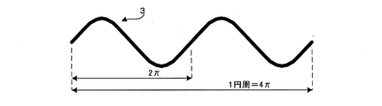
- FIG. 5 is a development view showing an example in which the linear shape pattern of the magnetic response member 3 is formed in a sine wave.
- the shape of the loop pattern of the secondary coils 6, 6a and 6b is not limited to the rectangular shape as illustrated, but may be any other shape such as sine wave or triangular wave.
- FIG. 6A shows an example in which the loop pattern of the secondary coil 6 is formed in a sine wave.
- the linear shape pattern of the magnetic response member 3 may also be sinusoidal as shown in FIG.
- FIG. 6B shows an example in which each loop area L1, L2, L3, L4 of the secondary coil 6 is formed in a flat spiral pattern.
- the winding directions of the spiral patterns of the adjacent loop areas L1, L2, L3 and L4 are opposite to each other as shown by the arrows in the figure.
- the linear shape pattern of the magnetic response member 3 is adapted also to it. It shall be modified appropriately.
- the upper side portions 3up1 and 3up2 correspond to the spiral pattern-like loop areas L1, L2, L3 and L4, and the lower side portions 3dn1 and 3dn2 have the spiral pattern-like loop areas L1 and L2 It does not correspond to L2, L3 and L4.
- the rotation detection device 1 has described an example in which the rotational position in the range less than one rotation (one circumference) of the rotating body 2 is detected in an absolute manner.
- the present invention is not limited to this, and also in the case of detecting the rotational position of the range over one rotation (one circumference) of the rotating body 2 in an absolute manner according to techniques known in this technical field, or one rotation of the rotating body 2 (one circle).
- the technical concept of the rotation detecting device according to the present invention can be applied to the case where the rotational position in the above range is detected in an absolute manner.
- the rotation detection device 1 can omit the primary coil 5 by using it in combination with another detection device (sensor) having an AC magnetic field generation function.
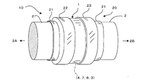
- FIG. 7 is a schematic external perspective view showing an example thereof, and shows an example in which the composite detection device 10 is configured by combining the rotation detection device 1 with a torque sensor 20 functioning as the other detection device (sensor). .
- the combined detection device 10 is configured to detect torque and rotational speed of a crankshaft of a pedal crank (not shown) of a motor-assisted bicycle (not shown). In this case, the crankshaft functions as the rotating body 2.
- left and right pedal cranks are respectively connected in the directions of arrows 2A and 2B, and drive sprockets (not shown) are arranged at predetermined positions of the crankshaft (rotary body 2).
- the drive sprocket is configured to drive a rear wheel drive chain (not shown), which is also engaged with a power assist sprocket (not shown).
- the power assist sprocket is driven by an electric motor (not shown).
- the pedaling force of the rider is detected and the crank rotational speed and the vehicle speed are detected, and the electric motor should be assisted by the detected stepping force and the crank rotational speed and the vehicle speed.
- a torque sensor 20 is provided on the crankshaft (rotating body 2), and functions to detect the pedal depression force by detecting a twisting torque generated on the crankshaft.
- the specific configuration of the torque sensor 20 may be any mechanism as long as it has at least a primary coil that generates an alternating magnetic field.
- the torque sensor 20 may be a magnetostrictive ring type torque sensor that detects a twist generated in the crankshaft (rotary body 2) using a magnetostrictive effect.
- the torque sensor 20 includes a ring-shaped magnetostrictive material 21 arranged to rotate together with the crankshaft (rotary body 2), and a predetermined position of the magnetostrictive material 21 has two rows of knurling patterns along the circumference.
- detection coils 22 and 23 are formed, and detection coils 22 and 23 are provided corresponding to each knurling pattern.
- Each detection coil 22 and 23 is excited by an AC signal to form an AC magnetic field, and generates a detection signal according to the magnetostrictive effect of the corresponding magnetostrictive material 21.
- the torsion (torque) of the crankshaft (rotary body 2) is detected based on the detection signals obtained from these detection coils 22 and 23.
- the detection coils 22 and 23 in the torque sensor 20 also function as primary coils in the rotation detection device 1 according to the present invention. That is, the rotation detection device 1 according to the present invention is disposed in the vicinity of the torque sensor 20 so as to be placed under the influence of the alternating magnetic field generated by the detection coils 22 and 23. In the example of FIG. 7, the rotation detection device 1 according to the present invention is disposed between the two detection coils 22 and 23.
- the rotation detection device 1 includes a magnetic response member 3 arranged to rotate together with the crankshaft (rotary body 2) and a stator 4, and the stator 4 has a ring on which the secondary coil 6 is arranged. Although it has the board
- the rotation detection device 1 By not having the dedicated primary coil 5, the structure of the rotation detection device 1 can be simplified.
- the configurations of the magnetic response member 3 and the secondary coil 6 are the same as those shown in the above embodiment, and the rotation detection is performed by the same operation.
- the rotation detection device 1 is used as a pedal crank rotational speed (rotational speed) sensor, but can also be used to detect a rotational position (angle) of the pedal crank.
- the present invention can be applied not only to pedal crank rotation number detection of a motor-assisted bicycle but also to any other application.
- the rotation detection device 1 according to the present invention may be used in combination with a torque sensor provided on a steering shaft of a steering wheel of an automobile. That is, by installing the composite detection device 10 according to the present invention in relation to the steering shaft of the steering wheel of the automobile (functioning as the rotating body 2), the detection of the steering torque and the steering angle is simplified. Depending on the configuration, this can be done effectively.
- the torque sensor 20 is not limited to the magnetostrictive sensor as described above, and may be based on any detection principle as long as it is a type including at least a primary coil for generating an alternating magnetic field.
Landscapes
- Physics & Mathematics (AREA)
- General Physics & Mathematics (AREA)
- Engineering & Computer Science (AREA)
- Chemical & Material Sciences (AREA)
- Combustion & Propulsion (AREA)
- Transportation (AREA)
- Mechanical Engineering (AREA)
- Electromagnetism (AREA)
- Transmission And Conversion Of Sensor Element Output (AREA)
- Measurement Of Length, Angles, Or The Like Using Electric Or Magnetic Means (AREA)
Abstract
小型化を促進するのに適した簡潔な構造を持つ回転検出装置を提供する。磁気応答部材(3)は、回転体(2)と共に回転するように該回転体の円周に沿って該回転体上に配置され、回転軸方向に周期的に変位する線形状のパターンからなる。ステータ(4)は、回転体(2)の周囲において非接触的に配置され、回転体(2)の周囲に巻回された1次コイル(5)と、回転体(2)の円周に沿って複数サイクルのループパターンを形成する2次コイル(6)とを含む。1次コイル(5)を交流励磁し、回転体(2)の回転位置に依存する磁気応答部材(3)の線形状のパターンと、2次コイル(6)の前記ループパターンとの相対位置に応じた誘導出力交流信号を2次コイル(6)から出力する。回転検出装置(10)それ自体は1次コイル(5)を持たず、1次コイル(5)を持つトルクセンサ(20)と組み合わせることで、複合型検出装置を構成し得る。
Description
本発明は、誘導型回転検出装置に関し、さらには、回転シャフトのトルクを検出するトルクセンサと組み合わせられた状態で、該回転シャフトの回転を検出する複合型検出装置に関し、電動アシスト自転車のペダルクランクシャフトの回転検出あるいは自動車のステアリングシャフトの回転検出などに適用可能なものである。
コイル(インダクタンス要素)を検出要素として使用する位置検出装置は従来より様々なタイプのものが知られている。装置構成の小型化という観点から、通常の円筒コイルを使用することなく、フラットなコイルを使用することが行われている。一例として、特許文献1に示されたものは、プリント基板上に渦巻き状に配置された小さなフラットコイルを検出要素として用いるものである。別の例として、特許文献2~6に示されたものは、フラットな基板上にループパターンを描くように導線を配置することにより、誘導コイルを構成している。位置検出装置において、前記コイルに磁気結合して、検出対象位置に応じて変位する磁気応答部材(又は磁気結合部材)は、鉄のような強磁性体あるいは銅のような良導体からなる金属素材が使用され、その面積あるいは体積が変化するような形状をなしている。
一方、自動車のステアリングシャフトにおいてトルクセンサと回転検出装置を組み合わせて備えることも、従来より種々知られている。下記特許文献7~9は、その一例を示す。特許文献7又は8に示されたものは、誘導型のトルクセンサと誘導型の回転位置検出装置をそれぞれ独立の構成として、ステアリングシャフトに設ける。特許文献9に示されたものは、ステアリングシャフトに誘導型のトルクセンサを設ける一方で、変速ギヤ機構を介して回転角検出手段を設ける。電動アシスト自転車のペダルクランクシャフトにおいてトルクセンサと回転検出装置を組み合わせて備えることも、従来より種々知られている。下記特許文献10~12は、その一例を示す。
特許文献1~6に示されたようなフラットな基板上に配置するコイルは、リニア位置検出装置には適しているが回転位置検出装置にはあまり適していない。また、磁気応答部材(又は磁気結合部材)の面積あるいは体積が検出対象位置に応じて変化するような構成にあっては、可動部分の構成を小型化することが困難である。
また、特許文献7~12に示されたようなトルクセンサと回転検出装置の組合せは、各センサ又は検出装置がそれぞれ独立の構成からなっているため、装置構成を簡素化するには限度があった。また、回転軸と回転検出装置との間に変速ギヤ機構を介在させる構成にあっては、ギャのバックラッシュによるガタツキが制御性能を低下させるおそれがあった。
本発明は、上述の点に鑑みてなされたもので、回転型の検出装置において小型化を促進するのに適した簡潔な構造を持つ回転検出装置を提供しようとするものであり、さらには、トルクセンサと組み合わせられた状態で回転シャフトの回転を検出する複合型検出装置を、簡素化した構成で提供することを目的とする。
本発明に係る回転検出装置は、回転体と共に回転するように該回転体の円周に沿って該回転体上に配置され、回転軸方向に周期的に変位する線形状のパターンからなる磁気応答部材と、前記回転体の周囲において非接触的に配置されたステータであって、前記回転体の円周に沿って複数サイクルのループパターンを形成する2次コイルを含む前記ステータとを備え、前記2次コイルは交流磁場に置かれ、前記回転体の回転位置に依存する前記磁気応答部材の線形状のパターンと前記2次コイルの前記ループパターンとの相対位置に応じた誘導出力交流信号を前記2次コイルから出力するようにしたものである。
本発明によれば、回転体上に配置された磁気応答部材は、回転軸方向に周期的に変位する線形状のパターンからなっているので、構造が簡潔であり、検出装置において小型化を促進するのに適している。また、ステータにおけるコイル構成においては、2次コイルが前記回転体の円周に沿って複数サイクルのループパターンを形成するように構成されているため、回転体の円周に沿ってコンパクトに装備されるのに適したものとなっている。こうして、回転型の検出装置において小型化を促進するのに適した簡潔な構造を持つ回転検出装置を提供することができる。
前記回転体は、回転検出対象である機械又は装置内に設けられた回転シャフトそれ自体であってよい。したがって、回転検出装置における専用のロータ部品を省略又は簡略化することができ、検出装置全体の小型化に一層寄与する。前記ステータは、前記交流磁場を発生するための1次コイルを含んでいてもよい。この1次コイルは、前記回転体の周囲に巻回された円筒コイルからなっていてもよく、これにより、簡潔な構成によって回転体の周囲に必要十分な交流磁界を発生させることができる。別の例として、前記ステータは前記1次コイルを含むことなく、この回転検出装置を、前記交流磁場を発生するための1次コイルを含んでいる他の検出装置に近接して配置するようにしてもよい。その場合、前記ステータに含まれる前記2次コイルは、前記他の検出装置の1次コイルから漏洩する交流磁場に置かれる。
例えば、この回転検出装置を、回転可能なシャフトに生じる捩れトルクを検出するトルクセンサと組み合わせることにより、複合型検出装置を構成するようにしてよい。その場合、前記トルクセンサは、交流磁場を発生するための1次コイルを少なくとも含むように構成されたものであるとよく、それにより、該トルクセンサを前記他の検出装置として機能させることができる。換言すれば、発明に係る複合型検出装置は、回転可能なシャフト(回転体)に生じる捩れトルクを検出するトルクセンサであって、交流磁場を発生するための1次コイルを少なくとも含む、前記トルクセンサと、前記シャフトの回転を検出するための回転検出装置とを具備し、前記回転検出装置は、前記シャフトと共に回転する回転体の円周に沿って該回転体上に配置され、回転軸方向に周期的に変位する線形状のパターンからなる磁気応答部材と、前記回転体の周囲において非接触的に配置されたステータであって、前記回転体の円周に沿って複数サイクルのループパターンを形成する2次コイルを含む前記ステータとを備え、前記2次コイルは前記トルクセンサの前記1次コイルから漏洩する前記交流磁場に置かれ、前記回転体の回転位置に依存する前記磁気応答部材の線形状のパターンと前記2次コイルの前記ループパターンとの相対位置に応じた誘導出力交流信号を、前記回転検出装置の前記2次コイルから出力することを特徴とする。
本発明に係る複合型検出装置によれば、回転検出装置は専用の1次コイルを持たず、前記ステータは2次コイルのみを含んでいればよいため、回転検出装置の構造を簡素化することができる。また、回転体上に配置された磁気応答部材は、回転軸方向に周期的に変位する線形状のパターンからなっているので、構造が簡潔であり、回転検出装置において小型化を促進するのに適している。また、ステータにおけるコイル構成においては、2次コイルが前記回転体の円周に沿って複数サイクルのループパターンを形成するように構成されているため、回転体の円周に沿ってコンパクトに装備されるのに適したものとなっている。こうして、小型化を促進するのに適した簡潔な構造を持つ複合型検出装置を提供することができる。さらに、変速ギヤ機構を必要としないため、ギャバックラッシュによる制御性能の低下が起こらない。
図1において、(a)は本発明の一実施例に係る回転検出装置1の外観を示す概略斜視図、(b)は該回転検出装置1の要部を分解して示す概略斜視図である。回転検出装置1は、回転体2の回転位置を検出するもので、該回転体2と共に回転するように該回転体2の円周に沿って該回転体2上に配置された磁気応答部材3と、該回転体2の周囲において非接触的に配置されたステータ4とで構成される。図1(a)において、矢印Rは回転体2の回転方向を示し、矢印Aは回転軸方向を示す。磁気応答部材3は、回転方向R及び回転軸方向Aに関して周期的に変位する線形状のパターンからなっており、鉄あるいはフェライトのような強磁性体素材又は銅あるいはアルミニウムのような良導電体素材からなる。回転体2の素材が鉄のような磁性体である場合、磁気応答部材3としては良導電体素材を用いるとよい。別の例として、回転体2の素材がアルミニウムのような導電体である場合、磁気応答部材3としては磁性体素材を用いるとよい。この磁気応答部材3のパターンは、メッキあるいは印刷若しくは焼き付け等適宜の加工技法によって回転体2の円周面に直接的に形成され得る。別の例として、磁気応答部材3のパターンは、非磁気応答素材からなる適宜のフィルム上に形成されていてもよく、そのようなフィルムを回転体2の円周面に接着剤を介して貼り付けることにより、該磁気応答部材3のパターンを回転体2上に配置し得る。なお、回転体2は、回転検出装置1の専用部品ではなく、該回転検出装置1を適用する(つまり、回転検出対象である)機械又は構造若しくは装置あるいは設備内に設けられた回転シャフトそれ自体であり、すなわち、回転検出対象である回転シャフトそれ自体である。したがって、回転検出装置1における専用のロータ部品を省略又は簡略化することができ、検出装置全体の小型化に寄与する。
ステータ4は、回転体2の周囲に巻回された1次コイル5と、該回転体2の円周に沿って複数サイクルのループパターンを形成する2次コイル6とを含む。典型的には、2次コイル6は、円周面を有するリング状の絶縁性の基板7上にリード線(導体)からなる所定のループパターンをプリント配線することにより構成し得る。すなわち、2次コイル6のループパターンは、回転体2の円周に沿って湾曲する基板7の円周面上に形成されている。1次コイル5は、よく知られたような円筒コイルからなっていてよい。円筒コイルからなる1次コイル5の内部に、2次コイル6を備えたリング状の基板7が配置されることにより、ステータ4のコイルアセンブリが構成される。そして、このステータ4のコイルアセンブリは、回転体2に嵌装され、該回転体2上に配置された磁気応答部材3の部分をコイルアセンブリ内に挿入した状態で固定される。通常知られているように、1次コイル5の入力端子には一定周波数の交流信号(例えばsinωt)が印加され、コイルアセンブリにおいて交流磁場が形成される。このように回転検出装置1を回転体2の所定位置に設置した状態で、回転体2が回転すると、その回転位置に応じて磁気応答部材3のパターンがステータ4のコイルアセンブリに対して相対的に変位し、この相対的変位に応じて1次コイル5と2次コイル6間の磁気結合度が変化し、回転位置に応じた出力信号が2次コイル6の出力端子から得られる。
図2(a)は、リング状の基板7上に配置された2次コイル6のループパターンを展開して例示する図である。2次コイル6は、リング状の基板7の1円周にわたって複数サイクルのループパターンを形成している。詳しくは、2次コイル6は、2つの出力端子O1,O2間に接続された、全体として一連のリード線(導体)からなり、該リード線が所定のパターンで蛇行しつつリング状基板7の1円周の行程を辿って折り返す(往復する)ことにより4つのループエリアL1,L2,L3,L4を形成している。各ループエリアL1,L2,L3,L4の回転方向Rの長さ(幅)は、概ね、円周の1/4である。図2(a)の例においては、各1つのループエリアL1,L2,L3,L4は上ラインup1,up2,up3,up4と下ラインdn1,dn2,dn3,dn4とを含み、各上ラインup1,up2,up3,up4は隣接するループエリアの下ラインdn1,dn2,dn3,dn4につながり、各下ラインdn1,dn2,dn3,dn4は隣接するループエリアの上ラインup1,up2,up3,up4につながる。これにより、各ループエリアL1,L2,L3,L4において、或る瞬間において上下の対向するリード線(つまり、上ラインと下ライン)を流れる電流の向きは、図中矢印で例示するように、互いに逆向きとなる。なお、図中矢印で例示した電流の向きは、出力端子O1,O2間からみれば同じ向きであることに注意されたい。なお、図2(a)の例においては、2次コイル6が概ね矩形状に蛇行するループパターンを形成している。これにより、各ループエリアL1,L2,L3,L4において、上ラインup1,up2,up3,up4は当該エリアの上辺において概ね直線状に延び、下ラインdn1,dn2,dn3,dn4は当該エリアの下辺において概ね直線状に延びている。
一方、2次コイル6の各ループエリアL1,L2,L3,L4において、1次コイル5からの交流磁場に応じて誘導される電流の方向は、上ラインup1,up2,up3,up4と下ラインdn1,dn2,dn3,dn4とで、同じ向きである。したがって、例えば、ループエリアL1において、上ラインup1と下ラインdn1に同量の電流が誘導されるとき、これらの誘導電流は相殺され、該ループエリアL1の部分における誘導電流の合計は0となる。あるいは、ループエリアL1の上ラインup1と下ラインdn1に誘導される電流が異なるとき、これらの誘導電流の差分が該ループエリアL1の部分において生じる。このように、上ラインup1,up2,up3,up4と下ラインdn1,dn2,dn3,dn4の誘導電流の差分が各ループエリアL1,L2,L3,L4の部分において生じ、それらの合計が2次コイル6の出力端子O1,O2間に生じることになる。
図2(b)は、回転体2上において円周方向に沿って配置された磁気応答部材3のパターンを展開して例示する図である。一例として、磁気応答部材3の線形状パターンは、1円周にわたって2サイクルで、回転軸A方向に周期的に変位する、矩形波状のパターンからなっている。展開図において、両端の部分3aと3a'は同一の部分である。すなわち、磁気応答部材3の2サイクル変化パターンはリング状につながっている。磁気応答部材3の矩形状パターンの1サイクルは、回転方向Rに直線状に延びた上辺部分3up1,3up2と、回転方向Rに直線状に延びた下辺部分3dn1,3dn2とを含む。上辺部3up1,3up2と下辺部分3dn1,3dn2は、回転方向R及び軸方向Aの両方に関してオフセットされている。上辺部分3up1,3up2及び下辺部分3dn1,3dn2の各々の回転方向Rの長さ(幅)は、円周の1/4である。
図2(a)に示された2次コイル6のループエリアL1,L2,L3,L4と、図2(b)に示されたような磁気応答部材3のパターンの対応関係について説明する。図2(a)と(b)に示すように、磁気応答部材3のパターンの上辺部分3up1がループエリアL1に略一致し、下辺部分3dn1がループエリアL2に略一致し、上辺部分3up2がループエリアL3に略一致し、下辺部分3dn2がループエリアL4に略一致した状態を、便宜上、同相状態ということにする。ループエリアL1について見ると、磁気応答部材3の上辺部分3up1が上ラインup1の全域にオーバーラップすることにより、上ラインup1に最大の誘導電流が流れ、その一方で、下ラインdn1には磁気応答部材3がオーバーラップしていないことにより、下ラインdn1の誘導電流は0である。したがって、上ラインup1の誘導電流は差し引かれることなく流れる。ループエリアL2については、磁気応答部材3の下辺部分3dn1が下ラインdn2の全域にオーバーラップすることにより、下ラインdn2に最大の誘導電流が流れ、その一方で、上ラインup2には磁気応答部材3がオーバーラップしていないことにより、上ラインup2の誘導電流は0である。したがって、下ラインdn2の誘導電流は差し引かれることなく流れ、上ラインup1の誘導電流に対して同相で加算される。ループエリアL3については前記ループエリアL1と同様に動作し、ループエリアL4については前記ループエリアL2と同様に動作する。この状態においては、各ループエリアL1,L2,L3,L4における磁気結合度は正の最大値であるということができる。したがって、この場合、2次コイル6の出力端子O1,O2間に最大レベルの誘導出力交流信号が生じる。
図2(c)は、回転体2が図2(b)の位置から磁気応答部材3のパターンの1/4サイクル相当の距離だけ変位した状態を示す展開図である。磁気応答部材3のパターンの1サイクルを2πで表すとすると、磁気応答部材3のパターンの1/4サイクル相当の距離はπ/2で表せる。この場合、図2(a)に示された2次コイル6のループエリアL1,L2,L3,L4に対する図2(c)に示された磁気応答部材3のパターンの相対位置関係は、上記同相状態に比べて1/4サイクルずれた状態となる。この場合、各ループエリアL1,L2,L3,L4における磁気結合度は正負同値となって相殺され、2次コイル6の出力端子O1,O2間の誘導出力交流信号のレベルは0となる。
図2(d)は、回転体2が図2(b)の位置から磁気応答部材3のパターンの1/2サイクル相当の距離だけ変位した状態を示す展開図である。磁気応答部材3のパターンの1/2サイクル相当の距離はπで表せる。この場合、図2(a)に示された2次コイル6のループエリアL1,L2,L3,L4に対する図2(d)に示された磁気応答部材3のパターンの相対位置関係は、上記同相状態に比べて1/2サイクルずれた状態(つまり逆相状態)となる。この場合、各ループエリアL1,L2,L3,L4における磁気結合度は負の最大値となる。したがって、この場合、2次コイル6の出力端子O1,O2間に最大レベルの誘導出力交流信号が生じる。ただし、図2(d)の位置関係において生じる最大レベルの誘導出力交流信号の電気的位相は、前記図2(b)の位置関係において生じる最大レベルの誘導出力交流信号の電気的位相に対して逆相となる。
図2(e)は、回転体2が図2(b)の位置から磁気応答部材3のパターンの3/4サイクル相当の距離だけ変位した状態を示す展開図である。磁気応答部材3のパターンの3/4サイクル相当の距離は3π/2で表せる。この場合、図2(a)に示された2次コイル6のループエリアL1,L2,L3,L4に対する図2(e)に示された磁気応答部材3のパターンの相対位置関係は、上記同相状態に比べて3/4サイクルずれた状態となる。この場合、各ループエリアL1,L2,L3,L4における磁気結合度は正負同値となって相殺され、2次コイル6の出力端子O1,O2間の誘導出力交流信号のレベルは0となる。
上述のように、2次コイル6の出力端子O1,O2間の誘導出力交流信号のレベルは、回転体2に設けられた磁気応答部材3のパターンの1サイクルに相当する回転変位を1サイクルとして周期的に変化する。したがって、2次コイル6の出力端子O1,O2間の誘導出力交流信号のレベルは回転体2の回転位置に関連した値を示すことになるので、該2次コイル6の出力端子O1,O2間の誘導出力交流信号に基づき回転体2の回転位置及び/又は回転速度を検出することができる。
図2(f)は、回転体2の1回転(1円周)にわたる変位にしたがって生じる、2次コイル6の出力端子O1,O2間の誘導出力交流信号のレベル変化の一例を示すもので、概ね、サイン関数特性(sinθ)のレベル変化を得ることができるように、磁気応答部材3のパターンと2次コイル6のループエリアL1,L2,L3,L4等との関係を設計した例を示す。この場合、磁気応答部材3のパターンは、回転体2の1回転(1円周)につき2サイクル配置されているので、上記サイン関数特性(sinθ)の角度変数θは、回転体2の1回転(1円周)につき4πの範囲で変化する。つまり、2次コイル6の出力端子O1,O2間の出力信号においては、回転体2の4分の1回転の範囲の回転位置をアブソリュート値で示すレベル変化が生じる。このサイン関数特性(sinθ)のレベルを示すデータは、公知のように、2次コイル6の出力端子O1,O2間の誘導出力交流信号(例えばsinθsinωt)を整流することにより得られる。
図2(g)は、回転体2の1回転(1円周)にわたる変位にしたがって生じる、2次コイル6の出力端子O1,O2間の誘導出力交流信号のレベル変化の別の一例を示すもので、概ね、三角波関数特性のレベル変化を得ることができるように、磁気応答部材3のパターンと2次コイル6のループエリアL1,L2,L3,L4等との関係を設計した例を示す。この場合も、磁気応答部材3のパターンは、回転体2の1回転(1円周)につき2サイクル配置されているので、上記三角波関数の角度変数θは、回転体2の1回転(1円周)につき4πの範囲で変化する。つまり、2次コイル6の出力端子O1,O2間の出力信号においては、回転体2の4分の1回転の範囲の回転位置をアブソリュート値で示すレベル変化が生じる。この三角波関数の角度変数θを示すデータも、公知のように、2次コイル6の出力端子O1,O2間の誘導出力交流信号を整流することにより得られる。
図2(f)及び(g)において、縦軸の+領域と-領域は、2次コイル6の出力端子O1,O2間の誘導出力交流信号の電気的位相が互いに逆相であることを示す。つまり、-領域における誘導出力交流信号のレベルの電気的位相は、+領域における誘導出力交流信号のレベルの電気的位相に対して逆相となる。なお、2次コイル6の出力端子O1,O2間の誘導出力交流信号のレベル変化の関数特性は、図2(f)又は(g)に示したようなサイン関数特性又は三角波関数特性に限らず、任意に設計可能である。
回転体2の回転位置を示すデータを得るために、図3(a)に示すように、2次コイル6の出力端子O1,O2間の誘導出力交流信号を整流回路11に入力してよい。整流回路11は、該誘導出力交流信号を整流してその振幅レベルを検出する(振幅レベルを示す直流電圧を出力する)。整流回路11は、2次コイル6から出力される前記誘導出力交流信号の振幅レベルを検出することに基づき前記回転体2の回転位置を示すデータを得る回路である。振幅レベルを示す直流電圧を出力する整流回路11に限らず、該誘導出力交流信号の振幅レベルをデジタル的に検出する回路を用いてもよい。
次に、回転体2の回転速度の測定例について図2(h)及び図3(b)を参照して説明する。図3(b)は回転速度用の回路構成例を示す。2次コイル6の出力端子O1,O2間の誘導出力交流信号をレベル比較回路12に入力し、該誘導出力交流信号の振幅レベルが所定の基準電圧Vrより大きいときレベル比較回路12から出力電圧を生じる。この基準電圧Vrは、図2(f),(g)に例示するように、図2(b)及び(d)に示すような位置関係において生じる誘導出力交流信号の最大レベルよりも小さな適宜の値である。レベル比較回路12の出力電圧はパルス成形回路13に入力され、交流信号成分を除去して平滑化したパルス波形として成形される。図2(h)は、パルス成形回路13から出力されるパルス波形を例示する。図2の例では、回転体2の1回転につき4個のパルス波形が生じる。パルス成形回路13から出力されるパルス波形は回転数カウント回路14に入力される。回転数カウント回路14は、パルス成形回路13から出力されるパルス波形の数をカウントし、所定の単位時間あたりのパルスカウント数から回転速度を検出する。レベル比較回路12、パルス成形回路13及び回転数カウント回路14は、2次コイル6から出力される前記誘導出力交流信号の振幅レベルに応じてパルス波形信号を生成し、該パルス波形信号に基づき回転体2の回転速度を示すデータを得る回路として機能する。
上記実施例ではリング状の基板7上に1つの2次コイル6のみを設けているが、これに限らず、円周方向の角度配置を互いにずらした状態で、2以上の2次コイル6を前記リング状の基板7上に配置するようにしてよい。例えば、2つの2次コイル6a,6bを重ね合わせて前記リング状の基板7上に配置する場合の各2次コイル6a,6bの展開図を図4に示し、(a)が2次コイル6aの展開図、(b)が2次コイル6bの展開図である。各2次コイル6a,6bは、上述の図2(a)に示すような2次コイル6と同一パターンからなっていてよいが、その円周方向の角度配置が磁気応答部材3のパターンの1/4サイクル相当の距離π/2だけ互いにずれるように配置される。これにより、一方の2次コイル6a(又は6b)の出力端子O1,O2間の誘導出力交流信号のレベル変化特性がサイン関数特性であるとすると、他方の2次コイル6b(又は6a)の出力端子O1,O2間の誘導出力交流信号のレベル変化特性がコサイン関数特性となるように設計することができる。すなわち、2つの2次コイル6a,6bから、回転変位成分θに対してサイン関数振幅特性を示す誘導出力交流信号sinθsinωtと、回転変位成分θに対してコサイン関数振幅特性を示す誘導出力交流信号cosθsinωtを得るようにすることができる。これは公知のレゾルバ型の回転検出装置と同様の出力信号であるから、このような2つの2次コイル6a,6bを備えた本発明に係る回転検出装置を公知のレゾルバ型の回転検出装置と同様の用途に応用することができる。
磁気応答部材3の線形状パターンは、図示のような矩形状のパターンに限らず、周期的に変位する線形状であれば、サイン波状あるいは三角波状などその他任意の形状であってよい。また、1円周あたりのサイクル数も任意に設計してよい。図5は、磁気応答部材3の線形状パターンをサイン波状に形成した例を示す展開図である。
2次コイル6,6a,6bのループパターンの形状も、図示のような矩形状のものに限らず、サイン波状あるいは三角波状などその他任意の形状であってよい。図6(a)は、2次コイル6のループパターンをサイン波状に形成した例を示す。図6(a)の場合、磁気応答部材3の線形状パターンも図5のようなサイン波状にするとよい。図6(b)は、2次コイル6の各ループエリアL1,L2,L3,L4をフラットな渦巻状のパターンで形成した例を示す。図6(b)の場合、各隣接するループエリアL1,L2,L3,L4の渦巻パターンの巻回方向は、図中矢印で示すように、互いに逆方向となる。なお、図6(b)に示すような渦巻パターン状のループエリアL1,L2,L3,L4からなる2次コイル6を使用する場合は、磁気応答部材3の線形状パターンもそれに適合するように適宜変形するものとする。例えば、磁気応答部材3の矩形状パターンのうち上辺部分3up1,3up2だけが渦巻パターン状のループエリアL1,L2,L3,L4に対応し、下辺部分3dn1,3dn2は渦巻パターン状のループエリアL1,L2,L3,L4に対応しないようにする。
上記実施例においては、説明の便宜上、回転検出装置1は、回転体2の1回転(1円周)に満たない範囲の回転位置をアブソリュートで検出する例について説明した。しかし、これに限らず、この技術分野で公知の技術に従い回転体2の1回転(1円周)にわたる範囲の回転位置をアブソリュートで検出する場合にも、あるいは回転体2の1回転(1円周)以上の範囲の回転位置をアブソリュートで検出する場合にも、本発明に従う回転検出装置の技術思想を適用することができる。
本発明に係る回転検出装置1は、交流磁場発生機能を持つ他の検出装置(センサ)と組み合わせて使用することにより、1次コイル5を省略することができる。図7は、その一例を示す概略外観斜視図であり、前記回転検出装置1を前記他の検出装置(センサ)として機能するトルクセンサ20と組み合わせることにより複合型検出装置10を構成した例を示す。この複合型検出装置10は、電動アシスト型自転車(図示せず)のペダルクランク(図示せず)のクランクシャフトのトルク及び回転数検出を行うように構成されている。この場合、該クランクシャフトが前記回転体2として機能する。図において、矢印2A及び2Bの方向には左右のペダルクランク(図示せず)がそれぞれ接続され、該クランクシャフト(回転体2)の所定箇所にドライブスプロケット(図示せず)が配置される。公知のように、ドライブスプロケットは後輪駆動用のチェーン(図示せず)を駆動するように構成されており、該チェーンはパワーアシスト用のスプロケット(図示せず)にも係合している。該パワーアシスト用のスプロケットは電気モータ(図示せず)によって駆動される。公知のように、電動アシスト型自転車においては、乗り手のペダル踏み込み力を検知すると共にクランク回転数及び車速を検知し、検知した踏み込み力とクランク回転数及び車速等に基づき前記電気モータによってアシストすべき動力を決定し、該決定した動力を生成するように該電気モータを駆動する仕組みを有している。
図7において、トルクセンサ20は、前記クランクシャフト(回転体2)に設けられており、該クランクシャフトに生じる捩れトルクを検出することにより、前記ペダル踏み込み力を検知するように機能するものである。このトルクセンサ20の具体的な構成は、少なくとも交流磁場を生成する1次コイルを有するものであれば、如何なる仕組みからなるものであってもよい。一例として、トルクセンサ20は、磁歪効果を利用して前記クランクシャフト(回転体2)に生じる捩れを検知する磁歪リング式トルクセンサであってよい。トルクセンサ20は、クランクシャフト(回転体2)と一緒に回転するように配置されたリング状の磁歪材21を含み、該磁歪材21の所定箇所には円周に沿って2列のナーリングパターン(凹凸)が形成されており、各ナーリングパターンに対応して検出コイル22及び23が設けられている。各検出コイル22及び23は、交流信号によって励磁されて交流磁場を形成し、対応する磁歪材21の磁歪効果に応じた検出信号を生成する。公知のように、これらの検出コイル22及び23から得られる検出信号に基づきクランクシャフト(回転体2)の捩れ(トルク)が検出される。
トルクセンサ20における検出コイル22及び23は、本発明に係る回転検出装置1における1次コイルとしても機能する。すなわち、本発明に係る回転検出装置1を、トルクセンサ20の近傍に配置し、検出コイル22及び23が発生する交流磁場の影響下に置かれるようにする。図7の例では、2つの検出コイル22及び23の間に本発明に係る回転検出装置1が配置される。この場合、回転検出装置1は、クランクシャフト(回転体2)と一緒に回転するように配置された磁気応答部材3と、ステータ4とを備え、ステータ4は、2次コイル6を配置したリング状の基板7を有するが、専用の1次コイル5は持たない。専用の1次コイル5を持たないことにより、回転検出装置1の構造を簡素化することができる。なお、磁気応答部材3及び2次コイル6の構成は、上記実施例に示したものと同様であり、同様の動作で回転検出を行う。この回転検出装置1は、ペダルクランクの回転数(回転速度)センサとして使用されるが、ペダルクランクの回転位置(角度)の検出にも使用可能である。
本発明に係る回転検出装置1を、交流磁場発生機能を持つ別のセンサと組み合わせて使用する場合、電動アシスト型の自転車のペダルクランク回転数検出に限らず、その他任意の用途に適用し得る。例えば、本発明に係る回転検出装置1を、自動車のハンドルのステアリングシャフトに設けられたトルクセンサと組み合わせて使用してもよい。すなわち、本発明に係る複合型検出装置10を、自動車のハンドルのステアリングシャフト(前記回転体2として機能する)に関連して設置することにより、ステアリングトルクとステアリング操舵角検出を、簡略化された構成によって効果的に行うことができる。なお、トルクセンサ20は、前述したような磁歪式センサに限らず、交流磁場を発生するための1次コイルを少なくとも含むタイプであれば、如何なる検出原理に基づくものであってもよい。
Claims (15)
- 回転体と共に回転するように該回転体の円周に沿って該回転体上に配置され、回転軸方向に周期的に変位する線形状のパターンからなる磁気応答部材と、
前記回転体の周囲において非接触的に配置されたステータであって、前記回転体の円周に沿って複数サイクルのループパターンを形成する2次コイルを含む前記ステータと
を備え、前記2次コイルは交流磁場に置かれ、前記回転体の回転位置に依存する前記磁気応答部材の線形状のパターンと前記2次コイルの前記ループパターンとの相対位置に応じた誘導出力交流信号を前記2次コイルから出力する回転検出装置。 - 前記回転体は、回転検出対象である機械又は装置内に設けられた回転シャフトそれ自体である、請求項1の回転検出装置。
- 前記2次コイルの前記ループパターンは、前記回転体の円周に沿って湾曲する基板の円周面上に形成されている、請求項1又は2の回転検出装置。
- 前記磁気応答部材の線形状パターンは矩形波状である、請求項1乃至3のいずれかの回転検出装置。
- 前記磁気応答部材の線形状パターンはサイン波状である、請求項1乃至3のいずれかの回転検出装置。
- 前記磁気応答部材は、メッキあるいは印刷若しくは焼き付けによって前記回転体の円周面に直接的に形成されている、請求項1乃至5のいずれかの回転検出装置。
- 前記磁気応答部材は、非磁気応答素材からなるフィルム上に形成されてなり、該フィルムを前記回転体の円周面上に貼り付けることにより、該回転体上に配置される、請求項1乃至5のいずれかの回転検出装置。
- 前記ステータは、前記交流磁場を発生するための1次コイルを含む、請求項1乃至7のいずれかの回転検出装置。
- 前記1次コイルは、前記回転体の周囲に巻回された円筒コイルからなる、請求項8の回転検出装置。
- 前記回転検出装置は、前記交流磁場を発生するための1次コイルを含んでいる他の検出装置に近接して配置され、
前記2次コイルは、該他の検出装置の前記1次コイルから漏洩する前記交流磁場に置かれる、請求項1乃至7のいずれかの回転検出装置。 - 前記2次コイルから出力される前記誘導出力交流信号の振幅レベルを検出することに基づき前記回転体の回転位置を示すデータを得る回路をさらに備える、請求項1乃至10のいずれかの回転検出装置。
- 前記2次コイルから出力される前記誘導出力交流信号の振幅レベルに応じてパルス波形信号を生成し、該パルス波形信号に基づき前記回転体の回転速度を示すデータを得る回路をさらに備える、請求項1乃至11のいずれかの回転検出装置。
- 前記ステータは、2つの前記2次コイルを含み、該2つの2次コイルの間で、前記ループパターンが前記回転体の円周に関して互いにずれており、一方の2次コイルから回転位置に対してサイン関数振幅特性を示す誘導出力交流信号を生じ、他方の2次コイルから回転位置に対してコサイン関数振幅特性を示す誘導出力交流信号を生じる、請求項1乃至12のいずれかの回転検出装置。
- 前記回転体として機能するシャフトの回転を検出するように構成された、請求項10の回転検出装置と、
前記シャフトに生じる捩れトルクを検出するトルクセンサと
を備え、前記トルクセンサが前記他の検出装置として機能する、複合型検出装置。 - 前記シャフトは、電動アシスト自転車のペダルクランクシャフト又は自動車のステアリングシャフトである、請求項14の複合型検出装置。
Priority Applications (4)
| Application Number | Priority Date | Filing Date | Title |
|---|---|---|---|
| US16/962,049 US11359909B2 (en) | 2018-01-23 | 2019-01-23 | Induction-type rotation detection device |
| EP19743368.3A EP3745080A4 (en) | 2018-01-23 | 2019-01-23 | INDUCTIVE ROTATION DETECTION DEVICE |
| JP2019567113A JP7178668B2 (ja) | 2018-01-23 | 2019-01-23 | 誘導型回転検出装置 |
| CN201980009526.7A CN111630341B (zh) | 2018-01-23 | 2019-01-23 | 感应型旋转检测装置 |
Applications Claiming Priority (2)
| Application Number | Priority Date | Filing Date | Title |
|---|---|---|---|
| JP2018-008985 | 2018-01-23 | ||
| JP2018008985 | 2018-01-23 |
Publications (1)
| Publication Number | Publication Date |
|---|---|
| WO2019146637A1 true WO2019146637A1 (ja) | 2019-08-01 |
Family
ID=67395597
Family Applications (1)
| Application Number | Title | Priority Date | Filing Date |
|---|---|---|---|
| PCT/JP2019/002073 Ceased WO2019146637A1 (ja) | 2018-01-23 | 2019-01-23 | 誘導型回転検出装置 |
Country Status (5)
| Country | Link |
|---|---|
| US (1) | US11359909B2 (ja) |
| EP (1) | EP3745080A4 (ja) |
| JP (1) | JP7178668B2 (ja) |
| CN (1) | CN111630341B (ja) |
| WO (1) | WO2019146637A1 (ja) |
Cited By (2)
| Publication number | Priority date | Publication date | Assignee | Title |
|---|---|---|---|---|
| JP2022104626A (ja) * | 2020-12-28 | 2022-07-08 | 株式会社ミツトヨ | 走査プローブ、方法、およびシステム |
| TWI859874B (zh) * | 2022-05-24 | 2024-10-21 | 巨大機械工業股份有限公司 | 轉矩感測器 |
Families Citing this family (3)
| Publication number | Priority date | Publication date | Assignee | Title |
|---|---|---|---|---|
| JP7459847B2 (ja) * | 2021-07-16 | 2024-04-02 | 株式会社デンソー | 位置検出装置およびブレーキペダル装置 |
| CN115014816B (zh) * | 2022-06-28 | 2025-07-08 | 湖南凌翔磁浮科技有限责任公司 | 一种感应环线测试系统及方法 |
| CN116418176B (zh) * | 2023-04-13 | 2023-11-21 | 哈尔滨理工大学 | 基于薄膜材料的绝对式角位移传感器装置及角度解算方法 |
Citations (15)
| Publication number | Priority date | Publication date | Assignee | Title |
|---|---|---|---|---|
| JPH08276887A (ja) | 1995-04-04 | 1996-10-22 | Honda Motor Co Ltd | アシストモータ付き自転車におけるクランクペダル位置制御装置 |
| JPH08290794A (ja) | 1995-04-21 | 1996-11-05 | Suzuki Motor Corp | 補助動力アシスト式自転車の補助動力アシスト装置 |
| JPH08313295A (ja) | 1995-05-16 | 1996-11-29 | Mitsutoyo Corp | 誘導電流を用いた位置検出トランスデューサ |
| US6236199B1 (en) | 1997-09-05 | 2001-05-22 | Hella Kg Hueck & Co. | Inductive angle sensor |
| US20020043972A1 (en) | 2000-05-25 | 2002-04-18 | Henning Irle | Inductive position sensor, particularly for a motor vehicle |
| JP2003121206A (ja) * | 2001-10-12 | 2003-04-23 | Mitsutoyo Corp | 磁気式エンコーダ |
| JP2003517595A (ja) * | 1999-12-14 | 2003-05-27 | エービービー アクチボラゲット | トルクセンサ |
| JP2005049180A (ja) | 2003-07-31 | 2005-02-24 | Amitec:Kk | 相対回転位置検出装置 |
| JP2006112815A (ja) | 2004-10-12 | 2006-04-27 | Mitsutoyo Corp | 誘導型変位検出装置 |
| JP2007269281A (ja) | 2006-03-31 | 2007-10-18 | Jtekt Corp | ステアリング装置 |
| JP2010122012A (ja) | 2008-11-18 | 2010-06-03 | Jtekt Corp | 基板形複層コイル及び変位センサ装置 |
| WO2013089206A1 (ja) | 2011-12-13 | 2013-06-20 | 株式会社アミテック | トルクセンサ |
| JP2014095651A (ja) | 2012-11-12 | 2014-05-22 | Mitsutoyo Corp | 誘導型変位検出装置 |
| JP2014153294A (ja) * | 2013-02-13 | 2014-08-25 | Mitsubishi Heavy Ind Ltd | 電磁誘導式位置検出器の検出位置補正方法 |
| JP2017206264A (ja) | 2012-12-17 | 2017-11-24 | ヤマハ発動機株式会社 | 駆動ユニット及び電動補助自転車 |
Family Cites Families (21)
| Publication number | Priority date | Publication date | Assignee | Title |
|---|---|---|---|---|
| DE3887853T2 (de) * | 1987-12-28 | 1994-05-19 | Kubota Ltd | Drehmomentmessvorrichtung. |
| JP3168451B2 (ja) * | 1995-09-24 | 2001-05-21 | 株式会社トプコン | ロータリーエンコーダ |
| US5841274A (en) * | 1997-01-29 | 1998-11-24 | Mitutoyo Corporation | Induced current absolute position transducer using a code-track-type scale and read head |
| AUPP482598A0 (en) * | 1998-07-24 | 1998-08-13 | Bishop Innovation Pty Limited | Angle encoder |
| ATE242930T1 (de) * | 1999-12-15 | 2003-06-15 | Bien Air Holding Sa | Bürstenlosen motor mit vorrichtung zur ermittlung der rotorstellung |
| JP2002107112A (ja) * | 2000-09-27 | 2002-04-10 | Koyo Seiko Co Ltd | 回転角度検出装置、トルク検出装置及び舵取装置 |
| JP2005121501A (ja) * | 2003-10-17 | 2005-05-12 | Minebea Co Ltd | タンデム型回転検出装置 |
| DE102004027954B4 (de) * | 2004-06-08 | 2018-06-14 | HELLA GmbH & Co. KGaA | Induktiver Winkelmesser, insbesondere für die Messung von Torsionswinkeln |
| CN101287978A (zh) * | 2005-07-11 | 2008-10-15 | Ncte工程有限公司 | 用于磁化可磁化元件的装置和传感器设备 |
| CN101629802A (zh) * | 2008-07-14 | 2010-01-20 | Tdk株式会社 | 角度检测装置和角度检测方法 |
| US8729887B2 (en) * | 2009-11-09 | 2014-05-20 | Aisan Kogyo Kabushiki Kaisha | Rotation angle sensor |
| JP5652181B2 (ja) * | 2010-12-10 | 2015-01-14 | 株式会社ジェイテクト | 回転角検出装置、トルク検出装置、及び電動パワーステアリング装置 |
| US8988066B2 (en) | 2011-03-02 | 2015-03-24 | Ksr Ip Holdings Llc | Steering position and torque sensor |
| JP6239824B2 (ja) * | 2013-01-18 | 2017-11-29 | 株式会社ミツトヨ | 誘導検出型ロータリエンコーダ |
| CN105308418B (zh) * | 2013-06-13 | 2018-05-08 | 株式会社阿米泰克 | 感应型位置检测装置 |
| JP6165541B2 (ja) * | 2013-07-26 | 2017-07-19 | Ntn株式会社 | 回転検出装置および回転検出装置付き軸受 |
| JP6277047B2 (ja) * | 2014-04-09 | 2018-02-07 | 株式会社ミツトヨ | 誘導検出型ロータリエンコーダ |
| CN105606018B (zh) * | 2014-09-03 | 2018-02-27 | 葛幸华 | 一种线圈都制作在定子上的分离式感应同步器 |
| CN204165509U (zh) * | 2014-09-03 | 2015-02-18 | 葛幸华 | 一种线圈都制作在定子上的分离式感应同步器 |
| DE102016201851B4 (de) * | 2016-02-08 | 2026-04-30 | Robert Bosch Gmbh | Sensorvorrichtung und Verfahren zur Bestimmung mindestens einer Rotationseigenschaft eines rotierenden Elements |
| CN107063075B (zh) * | 2017-05-27 | 2023-05-26 | 苏州昱泽智能科技有限公司 | 一种角度检测设备 |
-
2019
- 2019-01-23 CN CN201980009526.7A patent/CN111630341B/zh active Active
- 2019-01-23 WO PCT/JP2019/002073 patent/WO2019146637A1/ja not_active Ceased
- 2019-01-23 EP EP19743368.3A patent/EP3745080A4/en active Pending
- 2019-01-23 JP JP2019567113A patent/JP7178668B2/ja active Active
- 2019-01-23 US US16/962,049 patent/US11359909B2/en active Active
Patent Citations (15)
| Publication number | Priority date | Publication date | Assignee | Title |
|---|---|---|---|---|
| JPH08276887A (ja) | 1995-04-04 | 1996-10-22 | Honda Motor Co Ltd | アシストモータ付き自転車におけるクランクペダル位置制御装置 |
| JPH08290794A (ja) | 1995-04-21 | 1996-11-05 | Suzuki Motor Corp | 補助動力アシスト式自転車の補助動力アシスト装置 |
| JPH08313295A (ja) | 1995-05-16 | 1996-11-29 | Mitsutoyo Corp | 誘導電流を用いた位置検出トランスデューサ |
| US6236199B1 (en) | 1997-09-05 | 2001-05-22 | Hella Kg Hueck & Co. | Inductive angle sensor |
| JP2003517595A (ja) * | 1999-12-14 | 2003-05-27 | エービービー アクチボラゲット | トルクセンサ |
| US20020043972A1 (en) | 2000-05-25 | 2002-04-18 | Henning Irle | Inductive position sensor, particularly for a motor vehicle |
| JP2003121206A (ja) * | 2001-10-12 | 2003-04-23 | Mitsutoyo Corp | 磁気式エンコーダ |
| JP2005049180A (ja) | 2003-07-31 | 2005-02-24 | Amitec:Kk | 相対回転位置検出装置 |
| JP2006112815A (ja) | 2004-10-12 | 2006-04-27 | Mitsutoyo Corp | 誘導型変位検出装置 |
| JP2007269281A (ja) | 2006-03-31 | 2007-10-18 | Jtekt Corp | ステアリング装置 |
| JP2010122012A (ja) | 2008-11-18 | 2010-06-03 | Jtekt Corp | 基板形複層コイル及び変位センサ装置 |
| WO2013089206A1 (ja) | 2011-12-13 | 2013-06-20 | 株式会社アミテック | トルクセンサ |
| JP2014095651A (ja) | 2012-11-12 | 2014-05-22 | Mitsutoyo Corp | 誘導型変位検出装置 |
| JP2017206264A (ja) | 2012-12-17 | 2017-11-24 | ヤマハ発動機株式会社 | 駆動ユニット及び電動補助自転車 |
| JP2014153294A (ja) * | 2013-02-13 | 2014-08-25 | Mitsubishi Heavy Ind Ltd | 電磁誘導式位置検出器の検出位置補正方法 |
Non-Patent Citations (1)
| Title |
|---|
| See also references of EP3745080A4 |
Cited By (4)
| Publication number | Priority date | Publication date | Assignee | Title |
|---|---|---|---|---|
| JP2022104626A (ja) * | 2020-12-28 | 2022-07-08 | 株式会社ミツトヨ | 走査プローブ、方法、およびシステム |
| JP7814162B2 (ja) | 2020-12-28 | 2026-02-16 | 株式会社ミツトヨ | 走査プローブ、方法、およびシステム |
| TWI859874B (zh) * | 2022-05-24 | 2024-10-21 | 巨大機械工業股份有限公司 | 轉矩感測器 |
| US12618730B2 (en) | 2022-05-24 | 2026-05-05 | Giant Manufacturing Co., Ltd | Torque sensor for a bicycle or an electric bicycle |
Also Published As
| Publication number | Publication date |
|---|---|
| US20200408504A1 (en) | 2020-12-31 |
| CN111630341A (zh) | 2020-09-04 |
| JP7178668B2 (ja) | 2022-11-28 |
| US11359909B2 (en) | 2022-06-14 |
| JPWO2019146637A1 (ja) | 2021-01-07 |
| EP3745080A4 (en) | 2021-10-06 |
| CN111630341B (zh) | 2022-04-05 |
| EP3745080A1 (en) | 2020-12-02 |
Similar Documents
| Publication | Publication Date | Title |
|---|---|---|
| JP7178668B2 (ja) | 誘導型回転検出装置 | |
| US11525702B2 (en) | Sensor system for determining at least one rotation characteristic of a rotating element | |
| US8729887B2 (en) | Rotation angle sensor | |
| JP5337314B2 (ja) | 電動自転車のトルク及び速度センサ | |
| EP3009804B1 (en) | Inductive position-detecting device | |
| US8860405B2 (en) | Angle sensor | |
| US8421447B2 (en) | Position sensor | |
| EP2853861B1 (en) | Position detection device | |
| JP2012159495A (ja) | 位置センサ | |
| JP5016165B2 (ja) | 相対回転位置検出装置 | |
| US20210131830A1 (en) | Rotational angle sensor | |
| JP2001235307A (ja) | 回転型位置検出装置 | |
| KR101065220B1 (ko) | 모터 | |
| CN1945942B (zh) | 分相器的基准位置调整方法 | |
| WO2008053928A1 (en) | Rotation angle detection device | |
| US7999534B2 (en) | Rotation sensor with detection signal timing cycle features | |
| JP4336070B2 (ja) | 回転型位置検出装置 | |
| US20180226862A1 (en) | Rotational position detection device and motor device | |
| JP2023022766A (ja) | 回転角度検出装置 | |
| JP5135277B2 (ja) | 回転型位置検出装置 | |
| JP4369839B2 (ja) | 回転センサ | |
| JP7649932B1 (ja) | レゾルバ | |
| JP7649931B1 (ja) | レゾルバ | |
| JP2013225983A (ja) | レゾルバ | |
| JP5248559B2 (ja) | 位置検出センサ |
Legal Events
| Date | Code | Title | Description |
|---|---|---|---|
| 121 | Ep: the epo has been informed by wipo that ep was designated in this application |
Ref document number: 19743368 Country of ref document: EP Kind code of ref document: A1 |
|
| ENP | Entry into the national phase |
Ref document number: 2019567113 Country of ref document: JP Kind code of ref document: A |
|
| NENP | Non-entry into the national phase |
Ref country code: DE |
|
| ENP | Entry into the national phase |
Ref document number: 2019743368 Country of ref document: EP Effective date: 20200824 |