WO2019146663A1 - Dispositif ainsi que procédé de mesure de fluide, et programme - Google Patents
Dispositif ainsi que procédé de mesure de fluide, et programme Download PDFInfo
- Publication number
- WO2019146663A1 WO2019146663A1 PCT/JP2019/002148 JP2019002148W WO2019146663A1 WO 2019146663 A1 WO2019146663 A1 WO 2019146663A1 JP 2019002148 W JP2019002148 W JP 2019002148W WO 2019146663 A1 WO2019146663 A1 WO 2019146663A1
- Authority
- WO
- WIPO (PCT)
- Prior art keywords
- fluid
- frequency spectrum
- measurement device
- flow state
- unit
- Prior art date
- Legal status (The legal status is an assumption and is not a legal conclusion. Google has not performed a legal analysis and makes no representation as to the accuracy of the status listed.)
- Ceased
Links
Images



Classifications
-
- G—PHYSICS
- G01—MEASURING; TESTING
- G01F—MEASURING VOLUME, VOLUME FLOW, MASS FLOW OR LIQUID LEVEL; METERING BY VOLUME
- G01F1/00—Measuring the volume flow or mass flow of fluid or fluent solid material wherein the fluid passes through a meter in a continuous flow
- G01F1/66—Measuring the volume flow or mass flow of fluid or fluent solid material wherein the fluid passes through a meter in a continuous flow by measuring frequency, phase shift or propagation time of electromagnetic or other waves, e.g. using ultrasonic flowmeters
- G01F1/661—Measuring the volume flow or mass flow of fluid or fluent solid material wherein the fluid passes through a meter in a continuous flow by measuring frequency, phase shift or propagation time of electromagnetic or other waves, e.g. using ultrasonic flowmeters using light
-
- A—HUMAN NECESSITIES
- A61—MEDICAL OR VETERINARY SCIENCE; HYGIENE
- A61B—DIAGNOSIS; SURGERY; IDENTIFICATION
- A61B5/00—Measuring for diagnostic purposes; Identification of persons
- A61B5/02—Detecting, measuring or recording for evaluating the cardiovascular system, e.g. pulse, heart rate, blood pressure or blood flow
- A61B5/026—Measuring blood flow
- A61B5/0261—Measuring blood flow using optical means, e.g. infrared light
-
- A—HUMAN NECESSITIES
- A61—MEDICAL OR VETERINARY SCIENCE; HYGIENE
- A61B—DIAGNOSIS; SURGERY; IDENTIFICATION
- A61B5/00—Measuring for diagnostic purposes; Identification of persons
- A61B5/72—Signal processing specially adapted for physiological signals or for diagnostic purposes
- A61B5/7235—Details of waveform analysis
- A61B5/7253—Details of waveform analysis characterised by using transforms
-
- G—PHYSICS
- G01—MEASURING; TESTING
- G01F—MEASURING VOLUME, VOLUME FLOW, MASS FLOW OR LIQUID LEVEL; METERING BY VOLUME
- G01F1/00—Measuring the volume flow or mass flow of fluid or fluent solid material wherein the fluid passes through a meter in a continuous flow
- G01F1/66—Measuring the volume flow or mass flow of fluid or fluent solid material wherein the fluid passes through a meter in a continuous flow by measuring frequency, phase shift or propagation time of electromagnetic or other waves, e.g. using ultrasonic flowmeters
- G01F1/663—Measuring the volume flow or mass flow of fluid or fluent solid material wherein the fluid passes through a meter in a continuous flow by measuring frequency, phase shift or propagation time of electromagnetic or other waves, e.g. using ultrasonic flowmeters by measuring Doppler frequency shift
-
- A—HUMAN NECESSITIES
- A61—MEDICAL OR VETERINARY SCIENCE; HYGIENE
- A61B—DIAGNOSIS; SURGERY; IDENTIFICATION
- A61B2562/00—Details of sensors; Constructional details of sensor housings or probes; Accessories for sensors
- A61B2562/02—Details of sensors specially adapted for in-vivo measurements
- A61B2562/0233—Special features of optical sensors or probes classified in A61B5/00
Definitions
- the present disclosure relates to a fluid measurement device, a fluid measurement method, and a program.
- Patent Document 1 describes an apparatus that measures the flow rate optically.
- a fluid measurement apparatus includes a light emitting unit capable of emitting light toward an object including a fluid, a light receiving unit capable of receiving scattered light scattered by the fluid, and a frequency spectrum based on the scattered light. And a control unit having a generation unit to generate, and an estimation unit to estimate the flow state of the fluid based on the feature component of the frequency spectrum. Then, the control unit generates the first frequency spectrum based on the fluid to be measured and the second frequency spectrum based on the fluid in the known fluid state in the generation unit, and then the feature component of the first frequency spectrum and the second frequency spectrum The flow state of the fluid to be measured can be estimated by comparing the feature components of the estimation unit in the estimation unit.
- a fluid measurement method includes: irradiating light toward an object including a fluid and a flow path through which the fluid flows; receiving scattered light scattered by the fluid; and frequency based on the scattered light Generating a spectrum; and estimating a flow state of the fluid based on the feature components of the frequency spectrum. Then, the fluid measurement method according to one embodiment generates the first frequency spectrum based on the fluid to be measured and the second frequency spectrum based on the fluid in the known fluid state, and then the feature component of the first frequency spectrum. The flow state of the fluid to be measured can be estimated by comparing the characteristic components of the second frequency spectrum with the second frequency spectrum.
- a program comprises: causing a computer to emit light toward an object including a fluid and a flow path through which the fluid flows; receiving a scattered light scattered by the fluid; and based on the scattered light Generating a frequency spectrum; and estimating the fluid flow state based on the characteristic components of the frequency spectrum. Then, the program according to one embodiment causes the computer to generate the first frequency spectrum based on the fluid to be measured and the second frequency spectrum based on the fluid in the known fluid state, and then the first frequency spectrum The flow state of the fluid to be measured can be estimated by comparing the feature component with the feature component of the second frequency spectrum.
- the present disclosure relates to provision of a highly convenient fluid measurement device, fluid measurement method, and program. According to one embodiment, a highly convenient fluid measurement device, fluid measurement method, and program can be provided.
- a highly convenient fluid measurement device, fluid measurement method, and program can be provided.
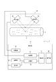
- FIG. 1 is a block diagram showing a schematic configuration example of a fluid measurement device according to an embodiment.
- FIG. 1 is a block diagram showing functional units included in a fluid measurement device according to an embodiment.
- FIG. 1 schematically shows the fluid A flowing in the flow path B. Further, a power supply for supplying power to each functional unit and a configuration for supplying power to each functional unit from the power supply are omitted.
- the fluid measurement device can calculate the flow state (flowing state) of a flowing object (fluid). Specifically, the fluid measurement device can calculate the flow rate or flow rate of the fluid as the fluid flow state.
- the flow rate is the volume or mass of the fluid flowing per unit time, and the flow rate is the distance traveled by the fluid per unit time.
- the fluid measurement device can calculate the fluid flow state using the Doppler effect of light.
- the light irradiated to the object to be irradiated (the fluid and the flow path through which the fluid flows, etc.) is scattered by the fluid, and the frequency is shifted (Doppler shift) by the Doppler effect according to the fluid flow state. Therefore, the flow state can be calculated by using the Doppler effect.
- the light emitting unit emits light toward the irradiated object including the fluid to be measured, and the interference light including the light scattered by the irradiated object is received by the light receiving unit. Can. Then, the fluid measurement device can calculate the fluid flow state based on the output of the light receiving unit.
- the fluid to be measured may be any fluid that can calculate the flow state using the Doppler effect of light.
- the fluid may be one that itself scatters light or one that causes a substance that scatters light (scattering substance) to flow.
- the fluid may be, for example, water, blood, an ink for a printer, or a gas containing powder.
- the fluid measurement device can also regard the flow rate or flow velocity of the scattering material or powder as the flow rate or velocity of the fluid. That is, "flow rate or flow rate of fluid” can also be interpreted as "flow rate or flow rate of scattering material or powder, etc.”
- a fluid measurement device 1 includes a control unit 10 that controls the fluid measurement device 1.
- the sensor unit 60 performs detection on the fluid A flowing in the flow path B. Then, in the fluid measurement device 1, the control unit 10 can estimate the flow state of the fluid A flowing in the flow path B based on the result detected by the sensor unit 60.
- the position of the sensor unit 60 may be positioned with respect to the flow path B so that the flow state of the fluid A flowing through the flow path B can be estimated.
- the sensor unit 60 includes a light emitting unit 62 and a light receiving unit 64.
- the light emitting unit 62 can emit light toward the flow path B.
- the light emitting unit 62 can emit, for example, a laser beam.
- the light emitter 62 may emit, as measurement light, laser light having a wavelength capable of detecting a specific component, such as fluid A or a solid contained in fluid A, for example.
- the light emitting unit 62 is configured of, for example, an arbitrary number of LDs (laser diodes).
- the light emitting unit 62 may be driven by the driving unit 50 of the control unit 10.
- the drive unit 50 may be configured by an arbitrary laser drive circuit or the like.
- the drive unit 50 may be provided outside the fluid measurement device 1 or may be incorporated in the sensor unit 60. As a result, the fluid measurement device 1 can improve the freedom of design.
- the light receiving unit 64 can receive the light scattered by the fluid A among the light emitted from the light emitting unit 62. Further, the light receiving unit 64 can receive the light scattered in the flow path B among the light emitted from the light emitting unit 62. That is, the light receiving unit 64 can receive the interference light including the light scattered by the fluid A and the light scattered by the flow path B.
- the light receiving unit 64 is configured of, for example, an arbitrary number of PDs (photodiodes: photo diodes).
- a signal (light signal) regarding the light received by the light receiving unit 64 is transmitted to the generation unit 12 of the control unit 10.
- the generation unit 12 will be described later.
- various amplifiers and / or filters may be used, but these are not shown.
- the sensor unit 60 is not limited to the configuration as shown in FIG.
- the sensor unit 60 does not include both the light emitting unit 62 and the light receiving unit 64 in one package, and the light emitting unit 62 and the light receiving unit 64 may be configured separately.
- the fluid measuring device 1 can improve the degree of freedom in design, the convenience can be improved.
- control unit 10 of the fluid measurement device 1 will be described.
- the control unit 10 of the fluid measurement device 1 includes a generation unit 12, an acquisition unit 14, and an estimation unit 16. Further, the control unit 10 may appropriately include at least one of the storage unit 20, the communication unit 30, the display unit 40, and the drive unit 50.
- the control unit 10 has at least one such as a central processing unit (CPU), for example, to provide control and processing capabilities for executing various functions such as the generation unit 12, the acquisition unit 14, and the estimation unit 16.
- a central processing unit CPU
- the control unit 10 may realize the functions of the generation unit 12, the acquisition unit 14, and the estimation unit 16 together by one processor, or may be realized by several processors, or each of them is individual It may be realized by a processor.
- the processor may be realized as an integrated circuit (IC) or a discrete circuit.
- the processor may be implemented based on various other known techniques.
- the functions of the generation unit 12, the acquisition unit 14, and the estimation unit 16 executed by the control unit may be configured as, for example, a CPU and a program executed by the CPU.
- the generation unit 12 can generate a frequency spectrum based on the output of the light receiving unit 64 of the sensor unit 60 and can output the frequency spectrum to the estimation unit 16.
- the acquisition unit 14 can acquire the frequency spectrum stored in the storage unit 20 and output the frequency spectrum to the estimation unit 16.
- the estimation unit 16 can estimate the flow state of the fluid A based on the frequency spectrum generated by the generation unit 12 and the frequency spectrum acquired by the acquisition unit 14.
- the storage unit 20 may be configured by a semiconductor memory, a magnetic memory, or the like.
- the storage unit 20 can store various information, a program to be executed, and the like.
- the storage unit 20 may function as a work memory of the acquisition unit 14 and / or the estimation unit 16.
- the storage unit 20 can store a frequency spectrum.
- the storage unit 20 may store in advance the frequency spectrum generated by the generation unit 12 or may store the frequency spectrum acquired by communication from the outside.
- the storage unit 20 may be various memory cards or the like.
- the communication unit 30 can realize various communication functions including wireless communication.
- the communication unit 30 may realize communication by various communication methods such as LTE (Long Term Evolution), for example.
- the communication unit 30 may include, for example, a modem whose communication system has been standardized in the International Telecommunication Union Telecommunication Standardization Sector (ITU-T).
- the communication unit 30 may wirelessly communicate with an external device such as an external server or a cloud server via, for example, an antenna via a network.
- the communication unit 30 may receive the second frequency spectrum S2 from an external database, such as, for example, an external server or a cloud server.
- the second frequency spectrum S2 received by the communication unit 30 in this manner may be stored in the storage unit 20.
- the display unit 40 can display various information such as the measurement result of the flow state of the fluid A on various display devices, and notify the user of the display.
- the display device may be a liquid crystal display (LCD), an organic EL display, an inorganic EL display, or the like.
- the display unit 40 may display an image such as a character, a figure, a symbol, or a graph.
- the display unit 40 may display an image such as an operation object.
- the information notified to the user by the display unit 40 is not necessarily limited to one that gives the user a visual effect.
- the display unit 40 may output various types of information as sound from the speaker as long as the information can be transmitted to the user.
- the storage unit 20, the communication unit 30, and the display unit 40 of the control unit 10 may be incorporated in the fluid measurement device 1 or may be provided outside the fluid measurement device 1. Also, for example, the display unit 40 may be incorporated in the sensor unit 60. As a result, the fluid measurement device can improve design freedom.
- the flow path B through which the fluid A flows may be a tube-shaped member made of various materials.
- the flow path B may be made of a material that transmits at least a part of the light emitted by the light emitting unit 62.
- the material of the flow path B may be, for example, plastic, vinyl chloride, or glass.
- the flow path B may be, for example, a body tissue through which human or animal body fluid such as a blood vessel flows.
- the flow path B may be configured so as not to leak the fluid A so that the flow state of the fluid A can be appropriately measured.
- FIG. 2 is a view for explaining detection of scattered light in fluid measurement according to one embodiment.
- FIG. 2 is a view for explaining detection of interference light by the fluid measurement device according to an embodiment.
- the fluid A contains a scattering material, and some are shown as white ovals for the convenience of description. Further, in FIG. 2, the scattering material flows to the right at velocity V.
- the light emitted from the light emitting unit 62 toward the flow path B includes the incident light Le1 and the incident light Le2.
- the incident light Le1 and the incident light Le2 are light of frequency f0 when irradiated from the light emitting unit 62.
- the incident light Le1 of frequency f0 is denoted by Le1 (f0)
- the incident light Le2 of frequency f0 is denoted by Le2 (f0).
- the incident light Le1 is interface-reflected on the surface of the stationary flow path B. That is, the incident light Le1 is not scattered by the fluid A, but is scattered by the surface of the flow path B.
- the incident light Le1 is scattered by the surface of the flow path B and becomes scattered light Lr1.
- the scattered light Lr1 is scattered by the surface of the flow path B where the incident light Le1 is stationary. At this time, the flow path B is stationary and the Doppler effect does not occur, so the frequency f0 of the incident light Le1 does not change.
- the scattered light Lr1 at the frequency f0 is denoted as Lr1 (f0).
- the incident light Le2 passes through the surface of the flow path B without interfacial reflection on the surface of the flow path B. That is, the incident light Le2 is scattered by the fluid A without being scattered by the surface of the flow path B. The incident light Le2 is scattered by the fluid A and becomes scattered light Lr2. At this time, since the incident light Le2 is scattered by the fluid A, the frequency f0 is Doppler-shifted.
- the scattered light Lr2 in which the frequency f0 has changed by the frequency ⁇ f is denoted as Lr2 (f0 + ⁇ f).
- the light receiving unit 64 receives the scattered light Lr1 and the scattered light Lr2 described above. Therefore, the fluid measurement device 1 can estimate the flow state of the fluid A, with the output of the light receiving unit 64 as one element.
- FIG. 3 is an example of a flowchart of flow state estimation performed by the control unit 10 of the fluid measurement device 1 according to an embodiment.
- the generation unit 12 beats the interference light generated by the interference between the scattered light Lr1 from the stationary flow path B and the irregular light Lr2 from the fluid A to be measured.
- Signal (beat signal) is acquired (step S1).
- the beat signal indicates the relationship between the strength of the beat and time.
- FIG. 4 is a diagram showing an example of the beat signal acquired in step S1 of FIG.
- the vertical axis in FIG. 4 represents the intensity of the signal output, and the horizontal axis represents time.
- the signal output from the light receiving unit 64 is a voltage value, and is shown as a signal output Vs in a unit of voltage (V).
- the beat signal is not limited to the voltage as long as it indicates a time change of the strength of the signal output.
- the signal output may be, for example, a current value or a resistance value.
- the generation unit 12 generates a frequency spectrum (first frequency spectrum) S1 based on the fluid to be measured based on the acquired beat signal (step S2).
- the frequency spectrum is a spectrum showing the relationship between the frequency f included in the beat signal and the intensity P (f) for each frequency.
- the generation unit 12 can generate a frequency spectrum by performing fast Fourier transform (FFT) on the beat signal acquired in step S1.
- FFT fast Fourier transform
- FIG. 5 is a diagram showing an example of a frequency spectrum.
- the vertical axis of FIG. 5 represents the intensity P (f) of an arbitrary unit, and the horizontal axis represents the frequency f.
- the frequency spectrum in the case where the flow velocity of the fluid A is 2 mm / s, 4 mm / s, 6 mm / s, 8 mm / s, 10 mm / s, and 14 mm / s is shown as an example.
- the fluid measurement device 1 can estimate the fluid flow state based on such a change in frequency spectrum.
- the estimation unit 16 can perform frequency weighting on the frequency spectrum P (f) (Formula (1)). That is, the product of each frequency f and its intensity P (f) can be calculated.
- the estimation part 16 can calculate the following integral value by integrating said Formula (1) in a suitable frequency range (Formula (2)). The estimation unit 16 multiplies the integral value obtained as shown in the above equation (2) by the proportionality constant K. Then, the estimation unit 16 normalizes the received light signal by dividing it by the total power (square of I), that is, the DC component so as not to depend on the received light intensity of light such as laser light. The following values can be calculated (Equation (3)).
- the estimation unit 16 compares the calculated value of the fluid to be measured with the equation (3) with the value of the equation (3) calculated by measuring the fluid in a known fluid state in advance, Flow conditions can be estimated.
- FIG. 6 is a diagram showing an example of the flow rate of the fluid estimated by the fluid measurement device 1 according to an embodiment.
- FIG. 6 shows, as an example, the time change of the blood flow rate in the blood vessel, that is, the blood flow rate.
- the blood flow shown on the vertical axis is an arbitrary unit.
- the fluid measurement device 1 estimates the fluid flow state based on the characteristic component (feature component) for each fluid flow state included in the frequency spectrum P (f). Can.
- the fluid measurement device 1 can reduce the effects of various noises, the estimation accuracy can be improved. That is, the fluid measurement device 1 can enhance the convenience.
- the intensity shown in the frequency spectrum is the sum of the scattered light component of the slow fluid and the component of the laser blur. That is, the measurement accuracy was reduced.
- the fluid measurement device 1 according to the embodiment can reduce the influence of noise, the estimation accuracy can be improved.
- the upper limit of the frequency axis when performing FFT analysis depends on the sampling rate. For this reason, the amount of Doppler shift of the frequency exceeding the upper limit of the frequency of FFT analysis was not observed. That is, as the flow rate or flow rate of the fluid increases, the measurement accuracy decreases. On the other hand, since the fluid measurement device 1 can estimate the flow state of the fluid based on various feature components, the estimation accuracy can be improved.
- the magnitude of the flow rate of the fluid also depends on the cross-sectional area of the flow path. That is, even in the case of the fluid having the same flow rate, the flow is quick if the flow passage is thin, and the flow is slow if the flow passage is thick. For this reason, when the flow rate was measured, it was difficult to measure the flow rate if the cross-sectional area of the flow path was unknown.
- the fluid measurement device 1 according to the embodiment can estimate the flow rate without necessarily using the information of the cross-sectional area of the flow path. That is, the fluid measurement device 1 can enhance the convenience.
- the fluid measurement device 1 can be measured noninvasively, and convenience can be improved.
- fluid measurement by fluid measurement device 1 concerning one embodiment is further explained.
- the acquisition unit 14 of the fluid measurement device 1 receives, from the storage unit 20, a frequency spectrum (second frequency spectrum) S2 based on a fluid in a known fluid state to be compared with the first frequency spectrum S1 acquired in step S2. It can be acquired (step S3).
- the fluid measurement device 1 measures in advance the fluid in the known fluid state, and stores the relationship between the known fluid state and the second frequency spectrum S2 generated by the generator 12 in the storage unit 20. Good.
- the fluid measurement device 1 may store the second frequency spectrum S2 in an external device such as an external server or a cloud server via the communication unit 30, for example.
- the acquisition unit 14 may acquire the second frequency spectrum S2 via the communication unit 30.
- the fluid measurement device 1 can shorten the measurement time by storing the second frequency spectrum in advance in the storage unit 20 or the like. That is, the fluid measurement device 1 can enhance the convenience.
- the known fluid state may be grasped by any method.
- the known flow state may be grasped using, for example, another flow meter such as a thermal type or an eddy current type, or a pump capable of flowing the fluid at a set flow rate.
- the fluid measurement device 1 may store the frequency spectrum as well as various measurement conditions for realizing the frequency spectrum.
- the measurement conditions may be, for example, conditions of an algorithm such as a sampling rate and an ADC conversion rate, or conditions of a measurement environment such as an air temperature and pressure.
- the fluid measurement device 1 includes intensity dispersion of the light emitting unit 62 configured by an LD, a frequency of light irradiated by the light emitting unit 62, a positional relationship between the flow passage B and the sensor unit 60, a cross sectional area of the flow passage B The material and material of the flow path B, noise in the assumed experimental environment, and the like may be appropriately recorded.
- the fluid measurement device 1 may also record the type of fluid, physical and chemical characteristics, and the like. As a result, since the fluid measurement device 1 can reduce the influence of measurement errors caused by the difference in measurement conditions, the estimation accuracy can be improved.
- the stored second frequency spectrum S2 and various variables for realizing the spectrum are appropriately updated by acquiring information from an external server or the like via the communication unit 30 regularly or irregularly. It is also good. As a result, since the conditions suitable for measurement can be selected suitably, the fluid measuring device 1 can improve convenience.
- the estimation unit 16 compares the feature component S1c of the first frequency spectrum S1 with the feature component S2c of the second frequency spectrum S2 (step S4).
- the acquisition unit 14 can select and acquire a second frequency spectrum S2 having a characteristic component suitable to be compared with the characteristic component S1c of the first frequency spectrum S1.
- the estimation unit 16 may estimate the flow state of the fluid A by adopting the second frequency spectrum S2 when the value of the following equation (4) is minimized and comparing it with the first frequency spectrum S1. .
- the fluid measurement device 1 can improve the estimation accuracy.
- one of F and f may be a value based on the first frequency spectrum S1, and the other may be a value based on the second frequency spectrum S2.
- the estimation unit 16 may add the intensity of the average frequency of the frequency spectrum as a variable to the equation (4).
- the intensity of the average frequency may be calculated by the following equation (5).
- the estimation unit 16 can calculate the intensity f of the average frequency in the first frequency spectrum S1 and the intensity F of the average frequency in the second frequency spectrum S2 based on the equation (5). Then, the estimation unit 16 adds the mean square error of the intensity f of the average frequency and the intensity F of the average frequency to the comparison expression as in the following expression (6), and corresponds to the second frequency spectrum S2 having the smallest value.
- the flowing state may be estimated as the flowing state to be measured. As a result, the fluid measurement device 1 can improve the estimation accuracy.
- the control unit 10 of the fluid measurement device 1 can extract feature components from the frequency spectrum stored as described above. As a result, since the fluid measurement device 1 can acquire the characteristic component for each fluid to be measured, the convenience can be enhanced.
- the storage unit 20 may further store the extracted feature component.
- the characteristic components of the frequency spectrum may be, for example, as follows.
- (1) Value of Intensity of Specific Frequency in Frequency Spectrum The control unit 10 can extract an intensity of a frequency with less noise as a feature component for each fluid to be measured. According to this, since the fluid measurement device 1 can reduce the noise of the measurement result, suitable measurement can be performed.
- the intensity of the frequency with little noise may be, for example, the intensity of the frequency at which the product of the frequency f and its intensity P (f) is maximum.
- Ratio of the intensity of a specific frequency in the frequency spectrum to the intensity of other specific frequencies According to this, it is possible to reduce noise common to the intensities of the respective frequencies. That is, since the estimation unit 16 can improve estimation accuracy, suitable measurement can be performed.
- the estimation unit 16 can smooth and standardize the measurement data, it becomes easy to grasp the feature of the intensity in each flow state. Therefore, the estimation unit 16 facilitates the comparison between the first frequency spectrum S1 and the second frequency spectrum S2. In addition, since noise common to the intensity of the angular frequency can be reduced, the estimation unit 16 can improve the estimation accuracy.
- (4) Value of Intensity Integrated in Specific Frequency Section of Frequency Spectrum The estimation unit 16 can select and calculate a frequency section with less noise. According to this, since the fluid measurement device 1 can reduce the noise of the measurement result, suitable measurement can be performed.
- the estimation unit 16 can improve the estimation accuracy.
- (5) Average of Intensity in Specific Frequency Section of Frequency Spectrum since the estimation unit 16 can smooth and standardize the measurement data, it becomes easy to grasp the characteristics of intensity in each flow state. Therefore, the estimation unit 16 facilitates the comparison between the first frequency spectrum S1 and the second frequency spectrum S2. Moreover, since the estimation part 16 can select and calculate the frequency area with few noises, it can calculate by reducing the influence of noise. That is, the estimation unit 16 can improve the estimation accuracy.
- the characteristic components as described above may be parameters that allow the first frequency spectrum S1 and the second frequency spectrum S2 to be compared, and are not limited to the above numerical values.
- the feature component may be in the form of a specific section in the power spectrum.
- the generation unit 12 can divide the beat signal into small predetermined times and generate the frequency spectrum at each predetermined time, a three-dimensional frequency spectrum indicating the passage of time may be prepared.
- the fluid measurement device 1 may extract feature components from such a three-dimensional frequency spectrum. According to this, it is possible to estimate the flow state from the tendency of the transition of the characteristic component accompanying the change of the flow state. That is, the trends of transitions of the characteristic components of the power spectrum do not necessarily have to match, and if it is determined that the trends of transitions of the entire power spectrum are the same or similar, it is possible to estimate the flow state. Therefore, the usefulness of the fluid measurement device 1 can be improved. In addition, since the amount of information that can be used for estimation increases, the fluid measurement device 1 can improve estimation accuracy.
- the extraction of characteristic components as described above may be used not only individually but also in combination of two or more of them. Also, for example, the feature component can be used in step S4 described later.
- the estimation unit 16 estimates the flow state of the fluid A based on the comparison result in step S4 (step S5), and ends the operation illustrated in FIG.
- the flow state of the fluid A estimated in step S5 may be, for example, at least one of the flow rate and the flow rate of the fluid A.
- the estimation unit 16 can estimate the fluid state corresponding to the feature component S2c of the second frequency spectrum S2 equivalent to or approximate to the feature component S1c of the first frequency spectrum S1 as the fluid state of the measurement target.
- the range in which the estimation unit 16 determines that the feature component S1c and the feature component S2c are similar may be determined arbitrarily by the user.
- the estimation unit 16 may estimate the flow state based on the shape of the curve of the specific frequency section of the frequency spectrum.
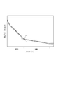
- 7 and 8 are diagrams for explaining the estimation method.
- the curve of the frequency spectrum is a concept including a straight line.
- the shape of the spectrum is, for example, a curve connecting maximum values of intensities of respective frequencies, or a curve connecting intermediate values of intensities. In other words, it is a set of maximum values of intensity of each frequency or a set of intermediate values.
- the estimation unit 16 may estimate the flow state by performing a two-linear approximation on the first frequency spectrum S1. First, the estimation unit 16 performs linear approximation from an arbitrary low frequency side frequency toward the high frequency side (for example, section 1 in FIG. 7). This linear approximation may be performed until the degree of approximation is degraded. Here, whether or not the degree of approximation is degraded may be determined, for example, by a chi-square test. Specifically, when the value obtained by dividing the chi-square value by the degree of freedom exceeds a specific threshold, it can be considered that the degree of approximation has deteriorated.
- the estimation unit 16 performs linear approximation in the low frequency direction from an arbitrary high frequency side frequency different from the end point of the first interval (for example, interval 2 in FIG. 7). Similar to the section 1, this linear approximation may be performed until the degree of approximation is degraded. Then, the estimation unit 16 can calculate an intersection point (point X in FIG. 7) of the two straight lines as the feature frequency f.
- the estimation unit 16 performs two-linear approximation also on the second frequency spectrum S2.
- the approximation method may be the same as that of the first frequency spectrum S1, and the estimation unit 16 can calculate the specific frequency F in the second frequency spectrum S2.
- the estimation unit 16 can estimate the flow state corresponding to the specific frequency F closest to the specific frequency f as the flow state to be measured.
- the estimation unit 16 may calculate the fluid state by approximating with an exponential function. First, the estimation unit 16 approximates the specific frequency section (for example, 2 kHz to 20 kHz) in the first frequency spectrum S1 and the second frequency spectrum S2 with an exponential function (for example, section 3 in FIG. 8). Next, the estimation unit 16 approximates the first frequency spectrum S1 to obtain the exponential function E1, and approximates the second frequency spectrum S2 to acquire the exponential function E2.
- an exponential function for example, section 3 in FIG. 8
- the estimation unit 16 may estimate the fluid state corresponding to the exponential function E2 having the parameter having the highest degree of agreement with the parameter of the exponential function E1 as the fluid state to be measured.
- the feature components extracted as exemplified above may be further weighted with the flow state using various learning techniques based on AI (Artificial Intelligence) such as machine learning or deep learning, for example. . That is, the fluid measurement device 1 may calculate the fluid flow state using various learning techniques.
- AI Artificial Intelligence
- the estimation unit 16 can cause various learning techniques to learn the relationship between the known fluid state and the feature component of the second frequency spectrum. Then, the estimation unit 16 can calculate the flow state of the fluid to be measured based on the characteristic components of the first frequency spectrum and the relationship between the flow state and the characteristic components weighted by various learning techniques. According to this, since the estimation unit 16 can improve the accuracy of the comparison between the first frequency spectrum S1 and the second frequency spectrum S2, the fluid measurement device 1 can improve the usefulness.
- the learning data may be the feature component exemplified above, and the teacher data may be a fluid flow state corresponding to the frequency spectrum.
- the fluid measurement device 1 may estimate the flow state based on feature components other than the above-described feature components, using the frequency spectrum as learning data and the flow state corresponding to the frequency spectrum as teacher data.
- the relationship between the flow state and the feature component obtained by learning may be appropriately stored in the storage unit 20 or the like.
- the characteristic component may be a ratio of the intensity corresponding to at least one specific frequency in the frequency spectrum to the intensity corresponding to at least one frequency other than the specific frequency.
- the feature component may be at least one of an average and a variance of intensities corresponding to a specific section in the frequency spectrum.
- the feature component may be in the form of a spectrum of a specific section in the frequency spectrum.
- the information on the flow state of the fluid A estimated in step 5 may be displayed on various display devices via the display unit 40, for example. Thereby, the user of the fluid measurement device 1 according to the embodiment can visually recognize the information on the flow state of the fluid A.
- the fluid flow state can be appropriately and accurately estimated under various conditions related to the fluid flow state.
- the fluid measurement device 1 can measure a relatively wide range of flow conditions with respect to a conventional laser Doppler flowmeter. That is, the fluid measurement device 1 according to one embodiment can improve convenience.
- each functional unit can be rearranged so as not to be logically contradictory.
- a plurality of functional units may be combined or divided into one.
- Each embodiment according to the present disclosure described above is not limited to be implemented faithfully to each described embodiment, and may be implemented by combining the respective features or omitting some of them as appropriate. .
- the embodiment described above is not limited to the implementation as the fluid measurement device 1.
- the embodiments described above may be implemented as a fluid measurement method as executed in the fluid measurement device 1 and a program that is executed by a computer that controls a device such as the fluid measurement device 1.
- the fluid measurement method includes the steps of: irradiating light toward an object including a fluid; receiving scattered light scattered by the fluid; and generating a frequency spectrum based on the scattered light. , Estimating the fluid flow state based on the feature components of the frequency spectrum. Then, the fluid measurement method according to one embodiment generates the first frequency spectrum based on the fluid to be measured and the second frequency spectrum based on the fluid in the known fluid state, and then the feature component of the first frequency spectrum. The flow state of the fluid to be measured can be estimated by comparing the characteristic components of the second frequency spectrum with the second frequency spectrum.
- a program includes the steps of: causing a computer to irradiate light toward an object including a fluid; receiving scattered light scattered by the fluid; and generating a frequency spectrum based on the scattered light And estimating the flow state of the fluid based on the characteristic components of the frequency spectrum. Then, the program according to one embodiment causes the computer to generate the first frequency spectrum based on the fluid to be measured and the second frequency spectrum based on the fluid in the known fluid state, and then the first frequency spectrum The flow state of the fluid to be measured can be estimated by comparing the feature component with the feature component of the second frequency spectrum.
Landscapes
- Health & Medical Sciences (AREA)
- Physics & Mathematics (AREA)
- Life Sciences & Earth Sciences (AREA)
- General Physics & Mathematics (AREA)
- Fluid Mechanics (AREA)
- Electromagnetism (AREA)
- Engineering & Computer Science (AREA)
- Public Health (AREA)
- Animal Behavior & Ethology (AREA)
- Biophysics (AREA)
- Pathology (AREA)
- Biomedical Technology (AREA)
- Heart & Thoracic Surgery (AREA)
- Medical Informatics (AREA)
- Molecular Biology (AREA)
- Surgery (AREA)
- Physiology (AREA)
- General Health & Medical Sciences (AREA)
- Veterinary Medicine (AREA)
- Measuring Volume Flow (AREA)
- Psychiatry (AREA)
- Hematology (AREA)
- Cardiology (AREA)
- Signal Processing (AREA)
- Computer Vision & Pattern Recognition (AREA)
- Artificial Intelligence (AREA)
- Measuring Pulse, Heart Rate, Blood Pressure Or Blood Flow (AREA)
Abstract
Selon un mode de réalisation de l'invention, un dispositif de mesure de fluide est équipé : d'une partie luminescente permettant d'irradier au moyen d'une lumière un objet à irradier contenant un fluide ; d'une partie de réception de lumière qui permet de recevoir une lumière diffuse diffusée par le fluide ; et d'une partie commande qui possède une partie génération générant un spectre de fréquence sur la base de la lumière diffuse, et une partie estimation estimant l'état d'écoulement d'un fluide sur la base d'un composant caractéristique du spectre de fréquence. En outre, la partie commande peut estimer l'état d'écoulement d'un fluide objet de la mesure par comparaison d'un composant caractéristique d'un premier spectre de fréquence et d'un composant caractéristique d'un second spectre de fréquence au moyen de la partie estimation, après génération du premier spectre de fréquence sur la base du fluide objet de la mesure et du second spectre de fréquence sur la base d'un fluide d'état d'écoulement déjà connu.
Priority Applications (4)
| Application Number | Priority Date | Filing Date | Title |
|---|---|---|---|
| EP19744512.5A EP3745097B1 (fr) | 2018-01-23 | 2019-01-23 | Dispositif ainsi que procédé de mesure de fluide, et programme |
| JP2019567126A JP6971332B2 (ja) | 2018-01-23 | 2019-01-23 | 流体測定装置、流体測定方法、及びプログラム |
| CN201980007436.4A CN111566456A (zh) | 2018-01-23 | 2019-01-23 | 流体测定装置、流体测定方法以及程序 |
| US16/964,104 US11226219B2 (en) | 2018-01-23 | 2019-01-23 | Fluid measurement apparatus, fluid measurement method, and program |
Applications Claiming Priority (2)
| Application Number | Priority Date | Filing Date | Title |
|---|---|---|---|
| JP2018008501 | 2018-01-23 | ||
| JP2018-008501 | 2018-01-23 |
Publications (1)
| Publication Number | Publication Date |
|---|---|
| WO2019146663A1 true WO2019146663A1 (fr) | 2019-08-01 |
Family
ID=67394735
Family Applications (1)
| Application Number | Title | Priority Date | Filing Date |
|---|---|---|---|
| PCT/JP2019/002148 Ceased WO2019146663A1 (fr) | 2018-01-23 | 2019-01-23 | Dispositif ainsi que procédé de mesure de fluide, et programme |
Country Status (5)
| Country | Link |
|---|---|
| US (1) | US11226219B2 (fr) |
| EP (1) | EP3745097B1 (fr) |
| JP (1) | JP6971332B2 (fr) |
| CN (1) | CN111566456A (fr) |
| WO (1) | WO2019146663A1 (fr) |
Families Citing this family (4)
| Publication number | Priority date | Publication date | Assignee | Title |
|---|---|---|---|---|
| JP7403674B2 (ja) * | 2020-09-16 | 2023-12-22 | 京セラ株式会社 | 測定装置、測定システム、プログラムおよび測定装置の校正方法 |
| US20230337926A1 (en) * | 2020-09-28 | 2023-10-26 | Kyocera Corporation | Measurement device, measurement system, measurement method, and non-transitory computer-readable recording medium |
| CN115165792B (zh) * | 2022-06-24 | 2023-09-29 | 宝腾智能润滑技术(东莞)有限公司 | 管线中气液两相流状态检测方法及装置 |
| CN118010116B (zh) * | 2024-04-09 | 2024-07-09 | 潍坊奥博仪表科技发展有限公司 | 一种抗干扰的超声波流量计量方法 |
Citations (5)
| Publication number | Priority date | Publication date | Assignee | Title |
|---|---|---|---|---|
| US6041662A (en) * | 1996-09-06 | 2000-03-28 | Endosonics Corporation | Process and apparatus for the determination of true average peak velocity |
| WO2015033469A1 (fr) * | 2013-09-09 | 2015-03-12 | パイオニア株式会社 | Appareil et procédé de détection de débit |
| JP2015132580A (ja) * | 2014-01-15 | 2015-07-23 | 株式会社ワイヤーデバイス | 管内を流れる粉体の流速測定方法及び測定装置 |
| JP2017113320A (ja) | 2015-12-24 | 2017-06-29 | パイオニア株式会社 | 流体評価装置及び方法、コンピュータプログラム並びに記録媒体 |
| JP2018009922A (ja) * | 2016-07-15 | 2018-01-18 | 日本電信電話株式会社 | 流体測定装置 |
Family Cites Families (14)
| Publication number | Priority date | Publication date | Assignee | Title |
|---|---|---|---|---|
| GB1450911A (en) * | 1973-01-17 | 1976-09-29 | Nat Res Dev | Laser doppler velocimetry |
| US3941477A (en) * | 1974-10-17 | 1976-03-02 | Deutsche Forschungs-Und Versuchsanstalt Fur Luft-Und Raumfahrt E.V. | Measuring device for the measurement of fluid flow rates |
| US6261233B1 (en) * | 1996-01-05 | 2001-07-17 | Sunlight Medical Ltd. | Method and device for a blood velocity determination |
| US6874480B1 (en) * | 2000-07-03 | 2005-04-05 | Combustion Dynamics Corp. | Flow meter |
| US6473705B1 (en) * | 2000-10-10 | 2002-10-29 | General Electric Company | System and method for direct non-intrusive measurement of corrected airflow |
| CA2459091C (fr) * | 2004-02-26 | 2012-08-14 | Photon Control Inc. | Dispositif et methode de detection de debit par fibre optique |
| WO2007001352A2 (fr) * | 2004-08-31 | 2007-01-04 | University Of Washington | Technique ultrasonore destinee a evaluer des vibrations de parois dans des vaisseaux sanguins stenoses |
| US7657392B2 (en) * | 2005-05-16 | 2010-02-02 | Cidra Corporate Services, Inc. | Method and apparatus for detecting and characterizing particles in a multiphase fluid |
| WO2010106483A2 (fr) * | 2009-03-18 | 2010-09-23 | Koninklijke Philips Electronics N.V. | Appareil de détermination d'une propriété d'écoulement d'un fluide |
| EP2336731A1 (fr) * | 2009-12-13 | 2011-06-22 | Fergus Jordan | Détection de gaspillage d'eau dans un système de distribution d'eau avec dispositif piézoélectrique |
| EP2612143A4 (fr) * | 2010-09-03 | 2017-01-18 | Los Alamos National Security LLC | Appareil et procédé pour la détection non invasive de particules à l'aide de la spectroscopie doppler |
| CN106290977B (zh) * | 2015-08-05 | 2020-01-10 | 水利部交通运输部国家能源局南京水利科学研究院 | 用多普勒超声波流速仪得到水流速信号的处理方法 |
| WO2017174977A1 (fr) * | 2016-04-04 | 2017-10-12 | Particulate As | Caractérisation de particules |
| CN107389144A (zh) * | 2017-07-27 | 2017-11-24 | 电子科技大学 | 一种井下流体流量测量方法及流量测量仪 |
-
2019
- 2019-01-23 JP JP2019567126A patent/JP6971332B2/ja not_active Expired - Fee Related
- 2019-01-23 CN CN201980007436.4A patent/CN111566456A/zh active Pending
- 2019-01-23 EP EP19744512.5A patent/EP3745097B1/fr active Active
- 2019-01-23 WO PCT/JP2019/002148 patent/WO2019146663A1/fr not_active Ceased
- 2019-01-23 US US16/964,104 patent/US11226219B2/en not_active Expired - Fee Related
Patent Citations (5)
| Publication number | Priority date | Publication date | Assignee | Title |
|---|---|---|---|---|
| US6041662A (en) * | 1996-09-06 | 2000-03-28 | Endosonics Corporation | Process and apparatus for the determination of true average peak velocity |
| WO2015033469A1 (fr) * | 2013-09-09 | 2015-03-12 | パイオニア株式会社 | Appareil et procédé de détection de débit |
| JP2015132580A (ja) * | 2014-01-15 | 2015-07-23 | 株式会社ワイヤーデバイス | 管内を流れる粉体の流速測定方法及び測定装置 |
| JP2017113320A (ja) | 2015-12-24 | 2017-06-29 | パイオニア株式会社 | 流体評価装置及び方法、コンピュータプログラム並びに記録媒体 |
| JP2018009922A (ja) * | 2016-07-15 | 2018-01-18 | 日本電信電話株式会社 | 流体測定装置 |
Also Published As
| Publication number | Publication date |
|---|---|
| US20210041274A1 (en) | 2021-02-11 |
| EP3745097A4 (fr) | 2021-10-13 |
| EP3745097B1 (fr) | 2023-11-08 |
| CN111566456A (zh) | 2020-08-21 |
| US11226219B2 (en) | 2022-01-18 |
| EP3745097A1 (fr) | 2020-12-02 |
| JPWO2019146663A1 (ja) | 2021-01-28 |
| JP6971332B2 (ja) | 2021-11-24 |
Similar Documents
| Publication | Publication Date | Title |
|---|---|---|
| JP6971332B2 (ja) | 流体測定装置、流体測定方法、及びプログラム | |
| JP6746002B2 (ja) | 流体測定装置、流体測定方法、及びプログラム | |
| CN109864744A (zh) | 测量生物信息的装置和方法 | |
| CN109314764A (zh) | 用于校准和修正散斑对比流量计的系统和方法 | |
| US20170273576A1 (en) | Living-body information measuring device | |
| WO2018012312A1 (fr) | Dispositif de mesure, procédé de mesure et programme de mesure | |
| US20170127955A1 (en) | Measurement apparatus and measurement method | |
| EP4220187A1 (fr) | Dispositif, système et procédé de mesure, et programme | |
| JP7011097B2 (ja) | 流体測定装置、流体測定方法、及びプログラム | |
| US20160360968A1 (en) | Fnirs system and sensor assembly | |
| US20230190121A1 (en) | Measurement device and estimation system | |
| WO2018062294A1 (fr) | Dispositif électronique, procédé de commande et programme | |
| JP2015150186A (ja) | 生体光計測装置 | |
| JP2015150186A5 (fr) | ||
| JP2012005598A (ja) | 生体情報計測装置及び生体情報計測方法 | |
| JP2019141410A (ja) | 生体情報測定装置、及び生体情報測定プログラム | |
| WO2016031222A1 (fr) | Appareil de mesure et procédé de mesure | |
| JP2022070650A (ja) | 測定装置、測定システム、測定方法及びプログラム |
Legal Events
| Date | Code | Title | Description |
|---|---|---|---|
| 121 | Ep: the epo has been informed by wipo that ep was designated in this application |
Ref document number: 19744512 Country of ref document: EP Kind code of ref document: A1 |
|
| ENP | Entry into the national phase |
Ref document number: 2019567126 Country of ref document: JP Kind code of ref document: A |
|
| NENP | Non-entry into the national phase |
Ref country code: DE |
|
| ENP | Entry into the national phase |
Ref document number: 2019744512 Country of ref document: EP Effective date: 20200824 |