WO2019150432A1 - 脱硫システム - Google Patents
脱硫システム Download PDFInfo
- Publication number
- WO2019150432A1 WO2019150432A1 PCT/JP2018/002979 JP2018002979W WO2019150432A1 WO 2019150432 A1 WO2019150432 A1 WO 2019150432A1 JP 2018002979 W JP2018002979 W JP 2018002979W WO 2019150432 A1 WO2019150432 A1 WO 2019150432A1
- Authority
- WO
- WIPO (PCT)
- Prior art keywords
- inlet duct
- absorption tower
- gas
- desulfurization system
- flow
- Prior art date
- Legal status (The legal status is an assumption and is not a legal conclusion. Google has not performed a legal analysis and makes no representation as to the accuracy of the status listed.)
- Ceased
Links
Images








Classifications
-
- B—PERFORMING OPERATIONS; TRANSPORTING
- B01—PHYSICAL OR CHEMICAL PROCESSES OR APPARATUS IN GENERAL
- B01D—SEPARATION
- B01D53/00—Separation of gases or vapours; Recovering vapours of volatile solvents from gases; Chemical or biological purification of waste gases, e.g. engine exhaust gases, smoke, fumes, flue gases, aerosols
- B01D53/34—Chemical or biological purification of waste gases
- B01D53/46—Removing components of defined structure
- B01D53/48—Sulfur compounds
- B01D53/50—Sulfur oxides
- B01D53/501—Sulfur oxides by treating the gases with a solution or a suspension of an alkali or earth-alkali or ammonium compound
- B01D53/504—Sulfur oxides by treating the gases with a solution or a suspension of an alkali or earth-alkali or ammonium compound characterised by a specific device
-
- B—PERFORMING OPERATIONS; TRANSPORTING
- B01—PHYSICAL OR CHEMICAL PROCESSES OR APPARATUS IN GENERAL
- B01D—SEPARATION
- B01D53/00—Separation of gases or vapours; Recovering vapours of volatile solvents from gases; Chemical or biological purification of waste gases, e.g. engine exhaust gases, smoke, fumes, flue gases, aerosols
- B01D53/14—Separation of gases or vapours; Recovering vapours of volatile solvents from gases; Chemical or biological purification of waste gases, e.g. engine exhaust gases, smoke, fumes, flue gases, aerosols by absorption
- B01D53/18—Absorbing units; Liquid distributors therefor
-
- F—MECHANICAL ENGINEERING; LIGHTING; HEATING; WEAPONS; BLASTING
- F23—COMBUSTION APPARATUS; COMBUSTION PROCESSES
- F23J—REMOVAL OR TREATMENT OF COMBUSTION PRODUCTS OR COMBUSTION RESIDUES; FLUES
- F23J15/00—Arrangements of devices for treating smoke or fumes
- F23J15/02—Arrangements of devices for treating smoke or fumes of purifiers, e.g. for removing noxious material
- F23J15/04—Arrangements of devices for treating smoke or fumes of purifiers, e.g. for removing noxious material using washing fluids
-
- B—PERFORMING OPERATIONS; TRANSPORTING
- B01—PHYSICAL OR CHEMICAL PROCESSES OR APPARATUS IN GENERAL
- B01D—SEPARATION
- B01D2257/00—Components to be removed
- B01D2257/30—Sulfur compounds
- B01D2257/302—Sulfur oxides
-
- B—PERFORMING OPERATIONS; TRANSPORTING
- B01—PHYSICAL OR CHEMICAL PROCESSES OR APPARATUS IN GENERAL
- B01D—SEPARATION
- B01D2258/00—Sources of waste gases
- B01D2258/02—Other waste gases
- B01D2258/0283—Flue gases
-
- F—MECHANICAL ENGINEERING; LIGHTING; HEATING; WEAPONS; BLASTING
- F23—COMBUSTION APPARATUS; COMBUSTION PROCESSES
- F23J—REMOVAL OR TREATMENT OF COMBUSTION PRODUCTS OR COMBUSTION RESIDUES; FLUES
- F23J2215/00—Preventing emissions
- F23J2215/20—Sulfur; Compounds thereof
Definitions
- the present invention relates to a desulfurization system for purifying exhaust gas discharged from a combustion facility such as a boiler installed in a thermal power plant or factory, etc., and reduces the initial cost of the desulfurization device and the pump consumption power required for operation. Relates to possible desulfurization systems.
- the wet limestone gypsum method is widely used as a means for removing sulfur oxides in exhaust gas discharged from boilers and the like in thermal power plants. Sulfur oxides in the exhaust gas are removed from the exhaust gas by passing through the absorption tower circulating through the absorption slurry and in contact with the slurry.
- FIG. 9 is an explanatory view (side view) of a conventional desulfurization system.
- FIG. 10 is a view (front view) seen from the direction of arrow X in FIG. 11 is a cross-sectional view taken along line XI-XI in FIG.
- FIG. 12 is an explanatory diagram of the flow of exhaust gas in FIG.
- FIG. 13 is an explanatory diagram of a conventional desulfurization system, and is an explanatory diagram of a desulfurization system in which the height of the inlet duct is different from that in FIG. 9.
- FIG. 14 is a view (front view) seen from the direction of arrow XIV in FIG. 15 is a cross-sectional view taken along line XV-XV in FIG.
- FIG. 16 is an explanatory diagram of the flow of exhaust gas in FIG.
- the exhaust gas is introduced from a duct 06 connected to the upper liquid surface of the absorption slurry tank 03 disposed in the lower part of the absorption tower 02, and flows vertically upward.
- the absorption slurry is sprayed from a plurality of nozzles 04. Therefore, when exhaust gas flows through the absorption tower 02, sulfur oxides are removed by contacting the absorption slurry.
- the shape and size of the duct 06 (hereinafter referred to as the inlet duct) for introducing the exhaust gas into the absorption tower 02 are determined so that the flow velocity can be kept within a certain range (about 10 to 15 m / s). Has been.
- the horizontal width 06a is increased as compared with the configuration shown in FIG.
- the length 06b can be lowered. If the height 06b of the inlet duct 06 can be lowered, the overall height of the absorption tower 02 can be lowered, and the head of the circulation pump 07 (distance to lift the absorption slurry) can be lowered. The power required for the operation can be lowered.
- Patent Document 1 Japanese Patent Laid-Open No. 55-73319
- Patent Document 2 Japanese Patent Application Laid-Open No. 9-47631
- the ratio of the inlet duct flatness, the tower diameter of the absorption tower, and the inlet duct width is defined, whereby the inlet duct width is determined.
- Patent Document 3 Japanese Patent No. 5725725
- an unreacted gas passes through the vicinity of the inner wall of the absorption tower by discontinuously providing a gas blow-off prevention member along the circumferential direction at the inner peripheral end of the absorption tower. Can be prevented.
- FIG. 17 is an explanatory view of the spray density of the absorbing slurry, and is a side view corresponding to FIG.
- FIG. 18 is an explanatory view of the spray density of the absorbing slurry, and is a cross-sectional view corresponding to FIG.
- the absorption slurry sprayed from the plurality of nozzles 04 in the absorption tower 02 falls in the absorption tower 02 and spreads in the horizontal direction. Therefore, as shown in FIGS. 17 and 18, the absorption slurry sprayed from the plurality of nozzles 04 arranged in the horizontal direction has a higher density at the center of the cylindrical absorption tower 02, and is formed at the outer edge of the absorption tower 02. The density decreases as time goes on.
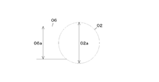
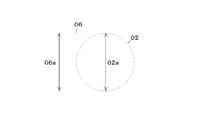
- the width 06a of the inlet duct 06 is set to be equal to the diameter 02a of the absorption tower 02. Therefore, as shown in FIG. also exhaust gas flows.
- the gas easily flows toward the center of the absorption tower 02, and the gas flow toward the outer edge is shown in FIGS.
- the number is reduced. Therefore, in the configuration in which the width 06a of the inlet duct 06 is widened, the exhaust gas easily flows to the outer edge portion where the density of the absorption slurry is low.
- the absorption performance of sulfur oxide hereinafter referred to as desulfurization performance
- the height 06b of the inlet duct 06 is increased.
- an expensive material such as Hastelloy steel excellent in acid resistance, corrosion resistance, and wear resistance.
- the height of the absorption tower 02 is increased, there is a problem that a range in which an expensive material is used is widened and an initial cost of the absorption tower 02 is increased. Further, when the height of the absorption tower 02 is increased, the lift of the circulation pump 07 becomes longer, and there is a problem that the power of the circulation pump 07 is increased.
- This invention makes it a technical subject to reduce the initial cost and pump power of the absorption tower of a desulfurization system, ensuring desulfurization performance.
- the invention according to claim 1, which solves the technical problem, includes contacting an inlet duct into which a gas to be processed flows, and a gas to be processed introduced from the inlet duct with an absorbing liquid, thereby causing sulfur oxide in the gas to flow. And an absorption tower for discharging the gas after the desulfurization treatment, and a width in the horizontal direction on the upstream side in the flow direction of the gas to be treated is wider than the diameter of the absorption tower, and a downstream end is connected to the absorption tower. And a desulfurization system comprising the inlet duct.
- the invention according to claim 2 is the desulfurization system according to claim 1, further comprising a flow control unit that biases the gas flow flowing through the inlet duct toward the center of the absorption tower. is there.
- the inlet duct into which the gas to be treated flows, and the gas to be treated introduced from the inlet duct are brought into contact with the absorption liquid to remove sulfur oxides in the gas, and after the desulfurization treatment
- a desulfurization system characterized by comprising:
- the horizontal width of the inlet duct is equal to or greater than the diameter of the absorption tower, and the flow of gas flowing through the inlet duct is biased toward the center of the absorption tower.
- the invention according to claim 6 is the desulfurization system according to claim 5, wherein the material of the inlet duct portion that does not contact the gas and the absorbing liquid by the rectifying plate is different from the material of the rectifying plate. is there.
- the invention according to claim 7 is characterized in that the flow control unit is configured by a downstream portion of the inlet duct having an inner wall shape inclined toward the center of the absorption tower.
- the desulfurization system according to any one of the above.
- the horizontal width of the inlet duct is equal to or larger than the diameter of the absorption tower, and the width of the inlet duct before being reduced by the flow control unit and the flow control unit are 6.
- the ratio of the length to the width of the inlet duct after being reduced is 0.95 or less, and the angle of the flow control unit for reducing the inlet duct is 45 degrees or less.
- a desulfurization system according to any one of 7 to 7.
- the height of the absorption tower can be reduced, and the gas flow is also reduced. It flows to the center side of the absorption tower, and the desulfurization performance of the desulfurization system can be secured. Therefore, the initial cost and pump power of the absorption tower of the desulfurization system can be reduced while ensuring the desulfurization performance.
- the flow control unit biases the gas flow flowing through the inlet duct toward the center of the absorption tower, whereby the inlet duct. Even if the width in the horizontal direction is increased, the gas can be sent to a region where the density of the absorbing solution is high in the absorption tower.
- the horizontal width of the inlet duct is widened by the flow control unit biasing the gas flow flowing through the inlet duct toward the center of the absorption tower,
- the gas can be sent to the region where the density of the absorbing liquid is high. Therefore, compared with the conventional configuration in which the gas is not biased toward the center of the absorption tower, the desulfurization of the gas is sufficiently performed, and the desulfurization performance of the desulfurization system can be ensured.
- the horizontal width of the inlet duct can be increased, the height of the inlet duct can be shortened and the height of the absorption tower can be reduced. Therefore, the cost of the absorption tower can be reduced, the head of the absorption liquid can be shortened, and the necessary power can be reduced.
- the cost of the absorption tower is reduced as compared with the case where the horizontal width of the inlet duct is less than the diameter of the absorption tower.
- the power for pumping up the absorbing liquid can also be reduced.
- the use of the current plate makes the structure of the inlet duct complicated and the occurrence of strength problems. Can be prevented.
- the material of the inlet duct portion that does not come into contact with the gas and the absorbent by the rectifying plate can be made a low-cost material. Can be reduced.
- an increase in the number of parts is prevented by controlling the gas flow in the shape of the inlet duct. it can.
- the height of the absorption tower can be reduced, and the pressure loss, wall flow velocity, and average flow velocity can be reduced. The difference can also be suppressed, and an increase in pressure loss due to the generation of vortices and adhesion of absorbing liquid can also be suppressed.
- FIG. 1 is a schematic explanatory view of an embodiment of the desulfurization system of the present invention.
- FIG. 2 is a view (front view) seen from the direction of arrow II in FIG. 3 is a cross-sectional view taken along line III-III in FIG.
- FIG. 4 is an explanatory diagram of a gas flow in the desulfurization system of the first embodiment.
- FIG. 5 is a graph showing the relationship between the squeeze ratio by the flow straightening plate, the flow velocity difference, and the pressure loss in the desulfurization system of Example 1.
- FIG. 6 is an explanatory diagram of a first modification of the present invention.
- FIG. 7 is an explanatory diagram of a second modification of the present invention.
- FIG. 8 is an explanatory diagram of a third modification of the present invention.
- FIG. 1 is a schematic explanatory view of an embodiment of the desulfurization system of the present invention.
- FIG. 2 is a view (front view) seen from the direction of arrow II in FIG.
- FIG. 9 is an explanatory view (side view) of a conventional desulfurization system.
- FIG. 10 is a view (front view) seen from the direction of arrow X in FIG. 11 is a cross-sectional view taken along line XI-XI in FIG.
- FIG. 12 is an explanatory diagram of the flow of exhaust gas in FIG.
- FIG. 13 is an explanatory diagram of a conventional desulfurization system, and is an explanatory diagram of a desulfurization system in which the height of the inlet duct is different from that in FIG. 9.
- FIG. 14 is a view (front view) seen from the direction of arrow XIV in FIG. 15 is a cross-sectional view taken along line XV-XV in FIG.
- FIG. 16 is an explanatory diagram of the flow of exhaust gas in FIG.
- FIG. 17 is an explanatory view of the spray density of the absorbing slurry, and is a side view corresponding to FIG.
- FIG. 18 is an explanatory view of the spray density of the absorbing slurry, and is a cross-sectional view corresponding to FIG.
- FIG. 1 is a schematic explanatory view of an embodiment of the desulfurization system of the present invention.
- a desulfurization system 1 of the present invention has an absorption tower 2.
- the absorption tower 2 is formed in a cylindrical shape whose inside extends in the vertical direction.
- An absorption slurry tank 3 in which an absorption slurry (absorption liquid) is accommodated is disposed in the lower part of the absorption tower 2.
- a plurality of nozzles 4 for spraying the absorption slurry are arranged in the upper part of the absorption tower 2.
- a plurality of nozzles 4 are arranged at intervals in the horizontal direction, and a plurality of nozzles 4 are arranged although not shown.
- Absorption slurry is pumped from the absorption slurry tank 3 by the circulation pump 7 and supplied to the nozzle 4.
- various conventionally known configurations can be employed. For example, since it is described in Japanese Patent No. 5725725 (Patent Document 3), Detailed description is omitted.
- FIG. 2 is a view (front view) seen from the direction of arrow II in FIG. 3 is a cross-sectional view taken along line III-III in FIG.
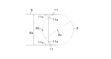
- FIG. 4 is an explanatory diagram of a gas flow in the desulfurization system of the first embodiment. 1 to 3, an inlet duct 6 for introducing exhaust gas (treated gas) into the absorption tower 2 is connected above the absorption slurry tank 3 and below the nozzle 4.
- the inlet duct 6 according to the first embodiment has a horizontal width 6 a that is equal to the inner diameter 2 a of the absorption tower 2. Accordingly, the height 6b of the inlet duct 6 is set shorter than when the horizontal width 6a is smaller than the inner diameter 2a of the absorption tower 2 (in the case of FIGS. 9 to 12).
- a pair of rectifying plates 11 as an example of a flow control unit are arranged at intervals in the width direction in the vicinity of a connection portion between the inlet duct 6 and the absorption tower 2. That is, the current plate 11 is disposed at the downstream end of the inlet duct 6 with respect to the gas flow direction.
- the rectifying plate 11 of the first embodiment is configured so that the gas flowing into the absorption tower 2 from the inlet duct 6 is biased toward the inner side in the horizontal direction (the central portion 2 c side of the absorption tower 2).
- the shape and position are set. Accordingly, the horizontal distance 11 b between the inner ends 11 a of the pair of rectifying plates 11 is set to be shorter than the width 6 a of the inlet duct 6.
- the upstream end 11 c of the rectifying plate 11 is disposed on the downstream side of the upstream end 2 b of the absorption tower 2. Therefore, the gas flow path of the first embodiment is narrowed inside the inlet (upstream end 2 b) of the absorption tower 2 by the rectifying member 11.
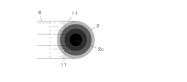
- Example 1 In the desulfurization system 1 of Example 1 having the above-described configuration, when exhaust gas flows into the absorption tower 2, the exhaust gas is deflected toward the central portion 2c of the absorption tower 2. Therefore, it becomes difficult for the exhaust gas to flow in the region where the density of the absorption slurry sprayed in the absorption tower 2 is low (see FIGS. 4, 17, and 18). Therefore, even if the width 6a of the inlet duct 6 is widened, the passage of the exhaust gas through the absorption tower 2 with insufficient desulfurization is reduced, and the desulfurization performance is ensured.
- the height 6b of the inlet duct 6 can be shortened, and the overall height of the absorption tower 2 and the head of the circulation pump 7 can be shortened. Therefore, it is possible to reduce the size of the desulfurization system 1 and reduce the cost of the absorption tower 2 and to reduce the power of the circulation pump 7.
- the width 6a of the inlet duct 6 is preferably equal to or greater than the diameter 2a of the absorption tower 2.
- FIG. 5 is a graph showing the relationship between the squeeze ratio by the flow straightening plate, the flow velocity difference, and the pressure loss in the desulfurization system of Example 1.
- the ratio (11b / 6a) of the width (6a) before squeezing with the rectifying plate 11 and the width (11b) after squeezing (11b / 6a) (hereinafter referred to as squeezing ratio), pressure loss, and side wall gas in the absorption tower 2
- squeezing ratio the ratio of the width (6a) before squeezing with the rectifying plate 11 and the width (11b) after squeezing (11b / 6a)
- the aperture ratio is preferably 0.95 or less, and more preferably the aperture ratio is in the range of 0.7 to 0.95.
- the angle ⁇ of the rectifying plate 11 for reducing the width 6a is a low angle at which vortices hardly occur.
- the inclination angle ⁇ of the upstream surface of the rectifying plate 11 with respect to the upstream wall surface of the inlet duct 6 is preferably 45 degrees or less.
- Example 1 since the gas flow path of Example 1 is restrict
- FIG. 1 When (squeezed), a part of the gas is movable in the vertical direction along the absorption tower 2. Therefore, when the gas flow path is throttled by the rectifying plate 11, a part of the gas escapes in the vertical direction, thereby suppressing the gas flow rate from becoming excessively high. Therefore, even if the gas flow is restricted by the rectifying plate 11, the gas flow rate can be kept within a certain range (about 10 to 15 m / s).
- FIG. 6 is an explanatory diagram of a first modification of the present invention.
- the shape of the downstream end portion 6 d (an example of a flow control unit) of the inlet duct 6 is configured so as to reduce the gas flow path instead of the rectifying plate 11. Is also possible. Although it is possible to reduce the number of parts by configuring as shown in FIG. 6, it is necessary to pay attention to the point that the structure of the inlet duct 6 is complicated and it is necessary to ensure the strength. Also in the configuration of the first modification shown in FIG. 6, as in the first embodiment, the cost and power can be reduced while ensuring the desulfurization performance.
- FIG. 7 is an explanatory diagram of a second modification of the present invention.
- the desulfurization system 1 of the first embodiment by installing the rectifying plate 11, a region 6 e that does not come into contact with the exhaust gas or the absorbed slurry to be sprayed is generated in the inlet duct 6.
- the conventional inlet duct 6 since it is in contact with the exhaust gas and the absorption slurry, it is necessary to use an acid-resistant, corrosion-resistant, and wear-resistant material. It is also possible to use inexpensive materials. With this configuration, the cost of the desulfurization system 1 can be further reduced.
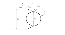
- FIG. 8 is an explanatory diagram of Modification 3 of the present invention.
- the horizontal width 6a of the inlet duct 6 is set wider than the absorption tower diameter 2a.
- the width of the inlet duct 6 is reduced to the diameter 2 a of the absorption tower 2 so that the inlet duct 6 is connected to the absorption tower 2.
- the desulfurization performance of the absorption tower 2 can be ensured by connecting the gas flow at the connection portion with the absorption tower 2 via the rectifying plate 11 so as to be directed to the central portion 2 c of the absorption tower 2.
- the shape of the rectifying plate 11 and the like can be changed to any shape according to the direction and direction of the gas flow to be controlled, such as a curve or a trapezoid.
- the structure which provided a pair of the baffle plates 11 in the width direction both sides was illustrated, it is not limited to this, If the flow can be biased toward the center part 2c of the absorption tower 2, one or three A configuration in which two or more are installed is also possible.
- the position of the upstream end 11c of the rectifying plate 11 is desirably disposed on the downstream side of the upstream end 2b of the absorption tower 2, but is not limited thereto.
- the upstream end 11c of the rectifying plate 11 can be arranged on the same side or on the upstream side of the upstream end 2b.
- the position of the inner end 11a of the rectifying plate 11 is preferably arranged upstream of the outermost peripheral position (11d in FIG. 7) of the absorption tower, but is not limited thereto.
- the position of the inner end 11a of the rectifying plate 11 can be arranged at the outermost peripheral position of the absorption tower. .
- the material of the rectifying plate 11 is preferably Hastelloy steel having excellent acid resistance, corrosion resistance, and wear resistance. However, other alloy steels, linings, and coating materials conforming to the above performance are used. It is also possible to use it.
- 1 desulfurization system, 2 ... Absorption tower, 2a ... Diameter of the absorption tower, 2c ... the center of the absorption tower, 6 ... Inlet duct, 6a: horizontal width of the inlet duct, 6d ... inner wall shape, 6e ... the inlet duct part not in contact with gas and absorbent, 11 ... Rectifying plate, 11, 6d ... flow control unit, 11b: width of the inlet duct after being reduced by the flow control unit, 11b / 6a ... ratio, ⁇ is the angle of the flow controller.
Landscapes
- Engineering & Computer Science (AREA)
- Chemical & Material Sciences (AREA)
- General Chemical & Material Sciences (AREA)
- Chemical Kinetics & Catalysis (AREA)
- Oil, Petroleum & Natural Gas (AREA)
- Analytical Chemistry (AREA)
- Environmental & Geological Engineering (AREA)
- Health & Medical Sciences (AREA)
- Biomedical Technology (AREA)
- Mechanical Engineering (AREA)
- General Engineering & Computer Science (AREA)
- Treating Waste Gases (AREA)
- Gas Separation By Absorption (AREA)
Abstract
被処理ガスが流入する入口ダクト(6)と、入口ダクト(6)から導入される被処理ガスを吸収液と接触させて、ガス中の硫黄酸化物を除去し脱硫処理後の排ガスを排出する吸収塔(2)と、入口ダクト(6)と吸収塔(2)との接続部の近傍に配置され、入口ダクト(6)を流れるガスの流れを、吸収塔(2)の中心部に向けて偏らせる流れ制御部(11)とを備えたことを特徴とする脱硫システム(1)により、脱硫性能を確保しつつ、脱硫システムの吸収塔の初期コスト及びポンプ動力を低減する。
Description
本発明は、火力発電所や工場等に設置されるボイラー等の燃焼設備から排出される、排ガスを浄化するための脱硫システムに係り、脱硫装置の初期コスト及び運転に必要なポンプ消費動力を低減可能な脱硫システムに関する。
火力発電所におけるボイラー等から排出される排ガス中の硫黄酸化物を除去する手段として、湿式石灰石石膏法が広く用いられている。排ガス中の硫黄酸化物は、吸収スラリを循環しスプレしている吸収塔を通過し、スラリと接触することで排ガス中から除去される。
図9は従来の脱硫システムの説明図(側面図)である。
図10は図9の矢印X方向から見た図(正面図)である。
図11は図10のXI-XI線断面図である。
図12は図11における排ガスの流れの説明図である。
図13は従来の脱硫システムの説明図であり、図9とは入口ダクトの高さが異なる脱硫システムの説明図である。
図14は図13の矢印XIV方向から見た図(正面図)である。
図15は図14のXV-XV線断面図である。
図16は図15における排ガスの流れの説明図である。
図10は図9の矢印X方向から見た図(正面図)である。
図11は図10のXI-XI線断面図である。
図12は図11における排ガスの流れの説明図である。
図13は従来の脱硫システムの説明図であり、図9とは入口ダクトの高さが異なる脱硫システムの説明図である。
図14は図13の矢印XIV方向から見た図(正面図)である。
図15は図14のXV-XV線断面図である。
図16は図15における排ガスの流れの説明図である。
図9、図13において、従来の脱硫システム01では、排ガスは吸収塔02の下部に配置された吸収スラリタンク03の液面上部に接続したダクト06から導入され、鉛直上方に流れる。吸収塔02内では、吸収スラリが複数のノズル04からスプレされる。したがって、排ガスが吸収塔02内を流れる際に、吸収スラリと接触することで、硫黄酸化物が除去される。
図11~図16において、排ガスを吸収塔02に導入するダクト06(以下、入口ダクト)部分については、流速を一定範囲(10~15m/s程度)に保てるように、形状・大きさが決定されている。
図11~図16において、排ガスを吸収塔02に導入するダクト06(以下、入口ダクト)部分については、流速を一定範囲(10~15m/s程度)に保てるように、形状・大きさが決定されている。
入口ダクト06の大きさについては、入口ダクト06の流路断面積が同一の場合、図10に示す構成に比べて、図14に示すように、水平方向の幅06aを広くすることで、高さ06bを低くすることができる。入口ダクト06の高さ06bを低くすることができれば、吸収塔02の全体の高さも低くすることができると共に、循環ポンプ07の揚程(吸収スラリを揚げる距離)を下げることができ、循環ポンプ07の動作に必要な動力を下げることができる。
そのため、入口ダクト06の断面積を変化させずに、入口ダクト06の高さ06bを下げる方法として、入口ダクト06の幅06aを吸収塔02の径02aと同等の大きさとした構成が考案されている。
そのため、入口ダクト06の断面積を変化させずに、入口ダクト06の高さ06bを下げる方法として、入口ダクト06の幅06aを吸収塔02の径02aと同等の大きさとした構成が考案されている。
このような湿式石灰石石膏法の吸収塔構造として、特許文献1(特開昭55-73319号公報)に記載の脱硫システムが知られている。
特許文献1では、吸収塔に排ガスを導入する入口ダクトを吸収塔塔径と同等まで水平方向に拡大することで吸収塔内のガス流速の偏流を抑制できるとしている。
また,特許文献2(特開平9-47631号公報)においても、特許文献1と同様に入口ダクトの偏平率と吸収塔の塔径と入口ダクト幅との割合を規定することで、入口ダクト幅を広げ、入口高さを低くすることで吸収塔内のガス流速の偏流を抑制でき、吸収塔高さを低くできるとしている。
一方、特許文献3(特許第5725725号公報)では吸収塔の内周端部にガス吹き抜け防止部材を周方向に沿って不連続に設けることで、吸収塔の内壁近傍を未反応ガスがすり抜けることを防止できるとしている。
特許文献1では、吸収塔に排ガスを導入する入口ダクトを吸収塔塔径と同等まで水平方向に拡大することで吸収塔内のガス流速の偏流を抑制できるとしている。
また,特許文献2(特開平9-47631号公報)においても、特許文献1と同様に入口ダクトの偏平率と吸収塔の塔径と入口ダクト幅との割合を規定することで、入口ダクト幅を広げ、入口高さを低くすることで吸収塔内のガス流速の偏流を抑制でき、吸収塔高さを低くできるとしている。
一方、特許文献3(特許第5725725号公報)では吸収塔の内周端部にガス吹き抜け防止部材を周方向に沿って不連続に設けることで、吸収塔の内壁近傍を未反応ガスがすり抜けることを防止できるとしている。
図17は吸収スラリのスプレ密度の説明図であり、図9に対応する側面図である。
図18は吸収スラリのスプレ密度の説明図であり、図11に対応する断面図である。
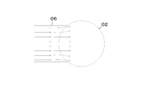
図17において、吸収塔02で複数のノズル04からスプレされる吸収スラリは、吸収塔02内を落下すると共に、水平方向に広がる。したがって、水平方向に並んだ複数のノズル04からスプレされた吸収スラリは、図17、図18に示すように、円筒状の吸収塔02の中心部ほど密度が高く、吸収塔02の外縁部にいくにつれて密度が低くなる。
図18は吸収スラリのスプレ密度の説明図であり、図11に対応する断面図である。
図17において、吸収塔02で複数のノズル04からスプレされる吸収スラリは、吸収塔02内を落下すると共に、水平方向に広がる。したがって、水平方向に並んだ複数のノズル04からスプレされた吸収スラリは、図17、図18に示すように、円筒状の吸収塔02の中心部ほど密度が高く、吸収塔02の外縁部にいくにつれて密度が低くなる。
ここで、図13~図16に示す従来構成では、入口ダクト06の幅06aが吸収塔02の径02aと同等に設定されているので、図16に示すように、吸収塔02の外縁部にも排ガスが流れ込む。一方、図9~図12に示す従来構成では、図12に示すように、吸収塔02の中央部に向けてガスが流れやすく、外縁部に向かうガスの流れは、図13~図16に示す従来構成に比べれば、少なくなる。したがって、入口ダクト06の幅06aを広くした構成では、吸収スラリの密度が低い外縁部に排ガスが流れやすい。吸収スラリの密度が低い吸収塔02の外縁部では、硫黄酸化物の吸収性能(以下、脱硫性能)が悪いため、入口ダクト06の幅06aを広げることで、脱硫性能が悪化する懸念があった。
特許文献1,2記載の構成では、吸収塔内の吸収液スプレの液密度が外周部ほど低くなっている点について考慮されておらず、スプレ液密度が低い吸収塔円周部壁面に排ガスが多く導入されるため、排ガスの吹き抜け(脱硫が不十分な状態で排ガスが吸収塔を上方に通過してしまう現象)が起こりやすく、脱硫性能が低下する恐れがあった。
また、特許文献3記載の構成のように,吸収塔壁面にガス吹き抜け防止部材を設置し、ガスの吹き抜けを防止する方法では、スプレ部の圧力損失が増加し、消費動力が大きくなる問題があった。
また、特許文献3記載の構成のように,吸収塔壁面にガス吹き抜け防止部材を設置し、ガスの吹き抜けを防止する方法では、スプレ部の圧力損失が増加し、消費動力が大きくなる問題があった。
さらに、脱硫性能低下の問題を考慮し、入口ダクト06の幅06aを狭くした場合には、入口ダクト06の高さ06bが高くなる。吸収塔02では、入口ダクト06の近傍は吸収スラリにより乾湿を繰り返すため、耐酸性、耐腐食性、耐摩耗性に優れたハステロイ鋼等の高価な材料を使用する必要がある。吸収塔02の高さが高くなると、高価な材料を使用する範囲が広くなり、吸収塔02の初期コストが増大する問題がある。また、吸収塔02の高さが高くなると、循環ポンプ07の揚程も長くなり、循環ポンプ07の動力が増加するという問題もあった。
本発明は、脱硫性能を確保しつつ、脱硫システムの吸収塔の初期コスト及びポンプ動力を低減することを技術的課題とする。
前記技術的課題を解決する請求項1に記載の発明は、被処理ガスが流入する入口ダクトと、前記入口ダクトから導入される被処理ガスを吸収液と接触させて、ガス中の硫黄酸化物を除去し、脱硫処理後のガスを排出する吸収塔と、前記被処理ガスの流れ方向の上流側で水平方向の幅が前記吸収塔の径より広く、且つ、下流端が前記吸収塔に接続された前記入口ダクトとを備えたことを特徴とする脱硫システムである。
請求項2に記載の発明は、前記入口ダクトを流れるガスの流れを、前記吸収塔の中心部に向けて偏らせる流れ制御部を備えたことを特徴とする請求項1に記載の脱硫システムである。
請求項3に記載の発明は、被処理ガスが流入する入口ダクトと、前記入口ダクトから導入される被処理ガスを吸収液と接触させて、ガス中の硫黄酸化物を除去し脱硫処理後のガスを排出する吸収塔と、前記入口ダクトと前記吸収塔との接続部の近傍に配置され、前記入口ダクトを流れるガスの流れを、前記吸収塔の中心部に向けて偏らせる流れ制御部とを備えたことを特徴とする脱硫システムである。
請求項4に記載の発明は、前記入口ダクトの水平方向の幅を、前記吸収塔の径と同等以上とし、前記入口ダクトを流れるガスの流れを、前記吸収塔の中心部に向けて偏らせる流れ制御部を設けたことを特徴とする請求項3に記載の脱硫システムである。
請求項5に記載の発明は、前記入口ダクトの内壁側に配置された整流板により構成された前記流れ制御部を備えたことを特徴とする請求項2ないし4のいずれかに記載の脱硫システムである。
請求項6に記載の発明は、前記整流板によってガスおよび吸収液に接触しない前記入口ダクト部分の材質が、前記整流板の材質とは異なることを特徴とする請求項5に記載の脱硫システムである。
請求項7に記載の発明は、前記吸収塔の中央に向けて傾斜する内壁形状を有する前記入口ダクトの下流部により構成された前記流れ制御部を備えたことを特徴とする請求項2ないし4のいずれかに記載の脱硫システムである。
請求項8に記載の発明は、前記入口ダクトの水平方向の幅を前記吸収塔の径と同等以上にし、且つ、前記流れ制御部で縮小される前の入口ダクトの幅と前記流れ制御部で縮小された後の入口ダクトの幅との長さの比率を、0.95以下とし、且つ、前記入口ダクトを縮小させる流れ制御部の角度を45度以下としたことを特徴とする請求項5ないし7のいずれかに記載の脱硫システムである。
請求項1記載の発明によれば、入口ダクトの水平方向の幅を吸収塔の径より広くし、吸収塔に接続することで、吸収塔の高さを低くすることができ、さらにガス流れも吸収塔の中央側に流れることとなり、脱硫システムの脱硫性能を確保できる。よって、脱硫性能を確保しつつ、脱硫システムの吸収塔の初期コスト及びポンプ動力を低減することができる。
請求項2記載の発明によれば、請求項1に記載の発明の効果に加えて、流れ制御部が入口ダクトを流れるガスの流れを吸収塔の中心部に向けて偏らせることで、入口ダクトの水平方向の幅を広げても、吸収塔内で吸収液の密度が高い領域にガスを送ることができる。
請求項3記載の発明によれば、流れ制御部が入口ダクトを流れるガスの流れを吸収塔の中心部に向けて偏らせることで、入口ダクトの水平方向の幅を広げても、吸収塔内で吸収液の密度が高い領域にガスを送ることができる。したがって、ガスを吸収塔の中心部に向けて偏らせない従来の構成に比べて、ガスの脱硫が十分に行われやすく、脱硫システムの脱硫性能を確保できる。また、入口ダクトの水平方向の幅を広げることができるので、入口ダクトの高さを短くすることができ、吸収塔の高さを低くすることができる。よって、吸収塔のコストを削減することができるとともに、吸収液の揚程を短くすることができ、必要な動力を低減することができる。
請求項4記載の発明によれば、請求項3に記載の発明の効果に加えて、入口ダクトの水平方向の幅を吸収塔の径と同等未満の場合に比べて、吸収塔のコストを削減でき、吸収液を汲み上げる動力も低減することができる。
請求項5記載の発明によれば、請求項2ないし請求項4のいずれかに記載の発明の効果に加えて、整流板を使用することで、入口ダクトの構造の複雑化や強度問題の発生を防止できる。
請求項6記載の発明によれば、請求項5に記載の発明の効果に加えて、整流板によってガスおよび吸収液に接触しない入口ダクト部分の材質を低コストの材質とすることができ、コストを削減できる。
請求項5記載の発明によれば、請求項2ないし請求項4のいずれかに記載の発明の効果に加えて、整流板を使用することで、入口ダクトの構造の複雑化や強度問題の発生を防止できる。
請求項6記載の発明によれば、請求項5に記載の発明の効果に加えて、整流板によってガスおよび吸収液に接触しない入口ダクト部分の材質を低コストの材質とすることができ、コストを削減できる。
請求項7記載の発明によれば、請求項2ないし請求項4のいずれかに記載の発明の効果に加えて、入口ダクトの形状でガスの流れを制御することで、部品点数の増加を防止できる。
請求項8記載の発明によれば、請求項5ないし請求項7のいずれかに記載の発明の効果に加えて、吸収塔の高さを削減できるとともに、圧力損失と壁面流速と平均流速との差も抑えることができ、渦の発生による圧力損失の増加や吸収液の付着も抑えることができる。
請求項8記載の発明によれば、請求項5ないし請求項7のいずれかに記載の発明の効果に加えて、吸収塔の高さを削減できるとともに、圧力損失と壁面流速と平均流速との差も抑えることができ、渦の発生による圧力損失の増加や吸収液の付着も抑えることができる。
以下に、本発明の実施の形態を示す。
図1は本発明の脱硫システムの一実施例の概略説明図である。
図1において、本発明の脱硫システム1は、吸収塔2を有する。吸収塔2は、内部が上下方向に延びる円筒状に形成されている。吸収塔2の下部には、吸収スラリ(吸収液)が収容される吸収スラリタンク3が配置されている。
吸収塔2の上部には、吸収スラリをスプレするノズル4が複数配置されている。ノズル4は、水平方向に間隔をあけて複数、また図示していないが複数段配置されている。ノズル4には、循環ポンプ7により、吸収スラリタンク3から吸収スラリが汲み上げられて供給される。なお、ノズル4の数や位置、数等の構成に関しては、従来公知の種々の構成を採用可能であり、例えば、特許第5725725号公報(特許文献3)等に記載されているため、図示や詳細な説明は省略する。
図1において、本発明の脱硫システム1は、吸収塔2を有する。吸収塔2は、内部が上下方向に延びる円筒状に形成されている。吸収塔2の下部には、吸収スラリ(吸収液)が収容される吸収スラリタンク3が配置されている。
吸収塔2の上部には、吸収スラリをスプレするノズル4が複数配置されている。ノズル4は、水平方向に間隔をあけて複数、また図示していないが複数段配置されている。ノズル4には、循環ポンプ7により、吸収スラリタンク3から吸収スラリが汲み上げられて供給される。なお、ノズル4の数や位置、数等の構成に関しては、従来公知の種々の構成を採用可能であり、例えば、特許第5725725号公報(特許文献3)等に記載されているため、図示や詳細な説明は省略する。
図2は図1の矢印II方向から見た図(正面図)である。
図3は、図2のIII-III線断面図である。
図4は実施例1の脱硫システムにおけるガスの流れの説明図である。
図1~図3において、吸収スラリタンク3の上方且つノズル4の下方には、排ガス(被処理ガス)を吸収塔2に導入する入口ダクト6が接続されている。実施例1の入口ダクト6は、水平方向の幅6aが、吸収塔2の内径2aと同等の長さに形成されている。したがって、水平方向の幅6aが吸収塔2の内径2aよりも小さい場合(図9~図12の場合)に比べて、入口ダクト6の高さ6bは短く設定されている。
図3は、図2のIII-III線断面図である。
図4は実施例1の脱硫システムにおけるガスの流れの説明図である。
図1~図3において、吸収スラリタンク3の上方且つノズル4の下方には、排ガス(被処理ガス)を吸収塔2に導入する入口ダクト6が接続されている。実施例1の入口ダクト6は、水平方向の幅6aが、吸収塔2の内径2aと同等の長さに形成されている。したがって、水平方向の幅6aが吸収塔2の内径2aよりも小さい場合(図9~図12の場合)に比べて、入口ダクト6の高さ6bは短く設定されている。
実施例1の脱硫システム1では、入口ダクト6と吸収塔2との接続部の近傍には、流れ制御部の一例としての整流板11が幅方向に間隔をあけて一対配置されている。すなわち、整流板11は、ガスの流れ方向に対して、入口ダクト6の下流端部に配置されている。図4に示すように、実施例1の整流板11は、入口ダクト6から吸収塔2に流入するガスを、水平方向の内側(吸収塔2の中心部2c側)に向けて偏らせるように形状および位置が設定されている。したがって、一対の整流板11の内端11aどうしの水平方向の距離11bは、入口ダクト6の幅6aよりも短く設定されている。
また、実施例1では、整流板11の上流端11cは、吸収塔2の上流端2bよりも下流側に配置されている。したがって、実施例1のガスの流路は、整流部材11により、吸収塔2の入口(上流端2b)よりも内側で絞られている。
前記構成を備えた実施例1の脱硫システム1では、排ガスが吸収塔2に流入する際に、排ガスが吸収塔2の中心部2cに向けて偏向される。よって、吸収塔2においてスプレされる吸収スラリの密度が低い領域(図4、図17、図18参照)に排ガスが流れにくくなる。したがって、入口ダクト6の幅6aを広げても、排ガスが、脱硫が不十分な状態で吸収塔2を通過することが低減され、脱硫性能が確保される。そして、入口ダクト6の幅6aを広げることで、入口ダクト6の高さ6bを短くすることができ、吸収塔2の全体の高さや、循環ポンプ7の揚程も短くすることができる。したがって、脱硫システム1の小型化や吸収塔2のコスト削減が可能であるとともに、循環ポンプ7の動力を低減することも可能である。特に、入口ダクト6の幅6aを広げるほど高さ6bを下げることができるため、入口ダクト6の幅6aは、吸収塔2の径2aと同等以上とすることが好ましい。
図5は実施例1の脱硫システムにおいて整流板による絞り比と流速差や圧力損失との関係を示すグラフである。
図5において、整流板11で絞る前の幅(6a)と、絞った後の幅(11b)との比率(11b/6a)(以下、絞り比)と圧力損失、吸収塔2内の側壁ガス流速と平均流速との差の関係を確認した。絞り比が小さくなると(整流板11の内端11aの幅11bが短くなると)、側壁ガス流速と平均流速との差がほとんど変わらないのに対して、圧力損失が大きくなっている。したがって、図5のグラフでは、絞り比が0.7を下回ると、それ以上幅11bを短くしても、圧力損失が増えるだけで、脱硫性能としてはほとんど変わらなくなる。
図5において、整流板11で絞る前の幅(6a)と、絞った後の幅(11b)との比率(11b/6a)(以下、絞り比)と圧力損失、吸収塔2内の側壁ガス流速と平均流速との差の関係を確認した。絞り比が小さくなると(整流板11の内端11aの幅11bが短くなると)、側壁ガス流速と平均流速との差がほとんど変わらないのに対して、圧力損失が大きくなっている。したがって、図5のグラフでは、絞り比が0.7を下回ると、それ以上幅11bを短くしても、圧力損失が増えるだけで、脱硫性能としてはほとんど変わらなくなる。
一方、図5において、絞り比が0.95を上回ると、側壁ガス流速と平均流速との差が急激に大きくなる。したがって、吸収スラリの密度が低い領域にガスが流れ込みやすくなって、排ガス中のSO2吸収に偏りが生じる恐れがある。
したがって、本構成を採用する際には、絞り比を0.95以下とすることが好ましく、より好適には絞り比を0.7~0.95の範囲とすることが好ましい。
したがって、本構成を採用する際には、絞り比を0.95以下とすることが好ましく、より好適には絞り比を0.7~0.95の範囲とすることが好ましい。
さらに、入口ダクト6の幅6aを整流板11で急角度で縮小させると、内端11aよりも下流側で渦が発生しやすくなる。渦が発生すると、圧力損失が増加したり、吸収スラリが付着する等の問題が発生する。したがって、幅6aを縮小させる整流板11の角度θは、渦が発生しにくい低角度とすることが望ましい。特に、入口ダクト6の上流側の壁面に対する整流板11の上流部の内面との傾斜角度θを、45度以下とすることが好ましい。
また、実施例1のガスの流路は、整流板11により、吸収塔2の入口(上流端2b)よりも内側で絞られているので、整流板11でガスが中心部2cに向けて偏る(絞られる)際には、ガスの一部が吸収塔2に沿って上下方向に移動可能な状態となっている。したがって、整流板11でガス流路が絞られる際に、ガスの一部が上下方向に抜けることで、ガスの流速が過剰に高速になることが抑制される。よって、整流板11でガスの流れが絞られても、ガスの流速を一定範囲(10~15m/s程度)に保つことが可能である。
また、実施例1のガスの流路は、整流板11により、吸収塔2の入口(上流端2b)よりも内側で絞られているので、整流板11でガスが中心部2cに向けて偏る(絞られる)際には、ガスの一部が吸収塔2に沿って上下方向に移動可能な状態となっている。したがって、整流板11でガス流路が絞られる際に、ガスの一部が上下方向に抜けることで、ガスの流速が過剰に高速になることが抑制される。よって、整流板11でガスの流れが絞られても、ガスの流速を一定範囲(10~15m/s程度)に保つことが可能である。
図6は本発明の変更例1の説明図である。
図6において、実施例1の脱硫システム1において、整流板11に変えて、入口ダクト6の下流端部6d(流れ制御部の一例)の形状を、ガス流路が縮小するように構成することも可能である。図6のように構成することで、部品点数を削減することが可能であるが、入口ダクト6の構造が複雑化し、強度を確保する必要がある点に気を付ける必要がある。
図6に示す変更例1の構成でも、実施例1と同様に、脱硫性能を確保しつつコストや動力を削減することができる。
図6において、実施例1の脱硫システム1において、整流板11に変えて、入口ダクト6の下流端部6d(流れ制御部の一例)の形状を、ガス流路が縮小するように構成することも可能である。図6のように構成することで、部品点数を削減することが可能であるが、入口ダクト6の構造が複雑化し、強度を確保する必要がある点に気を付ける必要がある。
図6に示す変更例1の構成でも、実施例1と同様に、脱硫性能を確保しつつコストや動力を削減することができる。
図7は本発明の変更例2の説明図である。
図7において、実施例1の脱硫システム1において、整流板11を設置することで、入口ダクト6には、排ガスやスプレされる吸収スラリに接触しない領域6eが発生する。従来の入口ダクト6では、排ガスや吸収スラリに接触するため、耐酸性、耐腐食性、耐摩耗性の材料を使用する必要があったが、整流板11が設置される領域6eについては、材料を廉価な材料を使用することも可能である。
このように構成することで、脱硫システム1のコストをさらに削減することが可能である。
図7において、実施例1の脱硫システム1において、整流板11を設置することで、入口ダクト6には、排ガスやスプレされる吸収スラリに接触しない領域6eが発生する。従来の入口ダクト6では、排ガスや吸収スラリに接触するため、耐酸性、耐腐食性、耐摩耗性の材料を使用する必要があったが、整流板11が設置される領域6eについては、材料を廉価な材料を使用することも可能である。
このように構成することで、脱硫システム1のコストをさらに削減することが可能である。
図8は本発明の変更例3の説明図である。図8において、入口ダクト6の水平方向の幅6aは、吸収塔の径2aより広く設定している。そして、入口ダクト6の下流端部では入口ダクト6の幅が、吸収塔2の径2aに縮小して、入口ダクト6が吸収塔2に接続されるように構成されている。この場合でも、吸収塔2との接続部でガス流れを吸収塔2の中心部2cに向かうように整流板11を介して接続することで、吸収塔2の脱硫性能を確保することができる。
(その他の変更例)
以上、本発明の実施例を詳述したが、本発明は、前記実施例に限定されるものではなく、特許請求の範囲に記載された本発明の要旨の範囲で、種々の変更を行うことが可能である。本発明の変更例(H01)~(H05)を下記に例示する。
(H01)前記実施例において、例示した具体的な数値は、設計や仕様等に応じて適宜変更可能である。
(H02)前記実施例において、流れ制御部の形状は、略三角形状(楔状)の整流板11や下流端部6dを例示したが、これに限定されない。整流板11等の形状は、曲線あるいは台形状等、制御したいガスの流れの向きや方向等に応じて、任意の形状に変更可能である。また、整流板11を幅方向の両側に一対設ける構成を例示したが、これに限定されず、吸収塔2の中心部2cに向けて流れを偏らせることが可能であれば、1つまたは3つ以上設置する構成とすることも可能である。
以上、本発明の実施例を詳述したが、本発明は、前記実施例に限定されるものではなく、特許請求の範囲に記載された本発明の要旨の範囲で、種々の変更を行うことが可能である。本発明の変更例(H01)~(H05)を下記に例示する。
(H01)前記実施例において、例示した具体的な数値は、設計や仕様等に応じて適宜変更可能である。
(H02)前記実施例において、流れ制御部の形状は、略三角形状(楔状)の整流板11や下流端部6dを例示したが、これに限定されない。整流板11等の形状は、曲線あるいは台形状等、制御したいガスの流れの向きや方向等に応じて、任意の形状に変更可能である。また、整流板11を幅方向の両側に一対設ける構成を例示したが、これに限定されず、吸収塔2の中心部2cに向けて流れを偏らせることが可能であれば、1つまたは3つ以上設置する構成とすることも可能である。
(H03)前記実施例において、整流板11の上流端11cの位置は、吸収塔2の上流端2bよりも下流側に配置することが望ましいがこれに限定されない。例えば、内端11aが上流端2bよりも下流側であれば、整流板11の上流端11cは、上流端2bより、同一または上流側に配置することも可能である。
(H04)前記実施例において、整流板11の内端11aの位置は、吸収塔の最外周位置(図7の11d)より上流側に配置することが望ましいが、これに限定されない。例えば、図8に示すように入口ダクトの幅6aを吸収塔の内径2aよりも大きくする場合は、整流板11の内端11aの位置を吸収塔の最外周位置に配置することも可能である。
(H05)前記実施例において、整流板11の材質は、耐酸性、耐腐食性、耐摩耗性に優れたハステロイ鋼等が望ましいが、上記の性能に準ずる他の合金鋼やライニングおよび塗布材料を使用することも可能である。
(H04)前記実施例において、整流板11の内端11aの位置は、吸収塔の最外周位置(図7の11d)より上流側に配置することが望ましいが、これに限定されない。例えば、図8に示すように入口ダクトの幅6aを吸収塔の内径2aよりも大きくする場合は、整流板11の内端11aの位置を吸収塔の最外周位置に配置することも可能である。
(H05)前記実施例において、整流板11の材質は、耐酸性、耐腐食性、耐摩耗性に優れたハステロイ鋼等が望ましいが、上記の性能に準ずる他の合金鋼やライニングおよび塗布材料を使用することも可能である。
1…脱硫システム、
2…吸収塔、
2a…吸収塔の径、
2c…吸収塔の中心部、
6…入口ダクト、
6a…入口ダクトの水平方向の幅、
6d…内壁形状、
6e…ガスおよび吸収液に接触しない入口ダクト部分、
11…整流板、
11,6d…流れ制御部、
11b…流れ制御部で縮小された後の入口ダクトの幅、
11b/6a…比率、
θ…流れ制御部の角度。
2…吸収塔、
2a…吸収塔の径、
2c…吸収塔の中心部、
6…入口ダクト、
6a…入口ダクトの水平方向の幅、
6d…内壁形状、
6e…ガスおよび吸収液に接触しない入口ダクト部分、
11…整流板、
11,6d…流れ制御部、
11b…流れ制御部で縮小された後の入口ダクトの幅、
11b/6a…比率、
θ…流れ制御部の角度。
Claims (8)
- 被処理ガスが流入する入口ダクトと、
前記入口ダクトから導入される被処理ガスを吸収液と接触させて、ガス中の硫黄酸化物を除去し、脱硫処理後のガスを排出する吸収塔と、
前記被処理ガスの流れ方向の上流側で水平方向の幅が前記吸収塔の径より広く、且つ、下流端が前記吸収塔に接続された前記入口ダクトと、
を備えたことを特徴とする脱硫システム。 - 前記入口ダクトを流れるガスの流れを、前記吸収塔の中心部に向けて偏らせる流れ制御部を備えたことを特徴とする請求項1に記載の脱硫システム。
- 被処理ガスが流入する入口ダクトと、
前記入口ダクトから導入される被処理ガスを吸収液と接触させて、ガス中の硫黄酸化物を除去し脱硫処理後のガスを排出する吸収塔と、
前記入口ダクトと前記吸収塔との接続部の近傍に配置され、前記入口ダクトを流れるガスの流れを、前記吸収塔の中心部に向けて偏らせる流れ制御部と、
を備えたことを特徴とする脱硫システム。 - 前記入口ダクトの水平方向の幅を、前記吸収塔の径と同等以上とし、前記入口ダクトを流れるガスの流れを、前記吸収塔の中心部に向けて偏らせる流れ制御部を備えたことを特徴とする請求項3に記載の脱硫システム。
- 前記入口ダクトの内壁側に配置された整流板により構成された前記流れ制御部、
を備えたことを特徴とする請求項2ないし4のいずれかに記載の脱硫システム。 - 前記整流板によってガスおよび吸収液に接触しない前記入口ダクト部分の材質が、前記整流板の材質とは異なる
ことを特徴とする請求項5に記載の脱硫システム。 - 前記吸収塔の中央に向けて傾斜する内壁形状を有する前記入口ダクトの下流部により構成された前記流れ制御部、
を備えたことを特徴とする請求項2ないし4のいずれかに記載の脱硫システム。 - 前記入口ダクトの水平方向の幅を前記吸収塔の径と同等以上にし、且つ、
前記流れ制御部で縮小される前の入口ダクトの幅と前記流れ制御部で縮小された後の入口ダクトの幅との長さの比率を、0.95以下とし、且つ、
前記入口ダクトを縮小させる流れ制御部の角度を45度以下とした
ことを特徴とする請求項5ないし7のいずれかに記載の脱硫システム。
Priority Applications (4)
| Application Number | Priority Date | Filing Date | Title |
|---|---|---|---|
| CN201880087556.5A CN111655357A (zh) | 2018-01-30 | 2018-01-30 | 脱硫系统 |
| PCT/JP2018/002979 WO2019150432A1 (ja) | 2018-01-30 | 2018-01-30 | 脱硫システム |
| JP2019568428A JP6938688B2 (ja) | 2018-01-30 | 2018-01-30 | 脱硫システム |
| EP18903598.3A EP3747531A4 (en) | 2018-01-30 | 2018-01-30 | DESULFURATION SYSTEM |
Applications Claiming Priority (1)
| Application Number | Priority Date | Filing Date | Title |
|---|---|---|---|
| PCT/JP2018/002979 WO2019150432A1 (ja) | 2018-01-30 | 2018-01-30 | 脱硫システム |
Publications (1)
| Publication Number | Publication Date |
|---|---|
| WO2019150432A1 true WO2019150432A1 (ja) | 2019-08-08 |
Family
ID=67479172
Family Applications (1)
| Application Number | Title | Priority Date | Filing Date |
|---|---|---|---|
| PCT/JP2018/002979 Ceased WO2019150432A1 (ja) | 2018-01-30 | 2018-01-30 | 脱硫システム |
Country Status (4)
| Country | Link |
|---|---|
| EP (1) | EP3747531A4 (ja) |
| JP (1) | JP6938688B2 (ja) |
| CN (1) | CN111655357A (ja) |
| WO (1) | WO2019150432A1 (ja) |
Cited By (1)
| Publication number | Priority date | Publication date | Assignee | Title |
|---|---|---|---|---|
| CN116637483A (zh) * | 2023-06-12 | 2023-08-25 | 安徽益沣石化有限公司 | 一种具有烟气余热回收利用功能的填料塔 |
Citations (9)
| Publication number | Priority date | Publication date | Assignee | Title |
|---|---|---|---|---|
| JPS5573319A (en) | 1978-11-30 | 1980-06-03 | Babcock Hitachi Kk | Gas and liquid contact apparatus |
| JPS5725725B2 (ja) | 1975-11-17 | 1982-05-31 | ||
| JPH08229339A (ja) * | 1994-12-28 | 1996-09-10 | Chiyoda Corp | 気液接触装置 |
| JPH0947631A (ja) | 1995-08-09 | 1997-02-18 | Babcock Hitachi Kk | 湿式排煙脱硫装置 |
| JPH119955A (ja) * | 1997-06-20 | 1999-01-19 | Ishikawajima Harima Heavy Ind Co Ltd | 排煙脱硫装置のスプレ式角型吸収塔 |
| JP2002502693A (ja) * | 1998-02-11 | 2002-01-29 | ザ・バブコック・アンド・ウイルコックス・カンパニー | 高速型の吸収塔におけるガス流れ模様の良好化を促進するための圧力低下の小さい入口設計形状 |
| WO2008035703A1 (en) * | 2006-09-19 | 2008-03-27 | Babcock-Hitachi Kabushiki Kaisha | Wet-type exhaust desulfurizing apparatus |
| JP2011062608A (ja) * | 2009-09-15 | 2011-03-31 | Mitsubishi Heavy Ind Ltd | 整流装置、co2回収装置 |
| JP2011218273A (ja) * | 2010-04-07 | 2011-11-04 | Babcock Hitachi Kk | 湿式排煙脱硫装置 |
Family Cites Families (14)
| Publication number | Priority date | Publication date | Assignee | Title |
|---|---|---|---|---|
| US3907526A (en) * | 1973-04-30 | 1975-09-23 | Peabody Engineering Corp | High velocity spray scrubber |
| JPS5242428U (en) * | 1975-09-22 | 1977-03-25 | Mitsubishi Heavy Ind Ltd | The drift prevention duct |
| JPS5592125A (en) * | 1979-01-05 | 1980-07-12 | Babcock Hitachi Kk | Gas contact device |
| GB9226129D0 (en) * | 1992-12-15 | 1993-02-10 | Baker Salah A | A process vessel |
| US5403523A (en) * | 1994-05-02 | 1995-04-04 | The Babcock & Wilcox Company | Wet scrubber inlet awning with low pressure drop |
| US6550751B1 (en) * | 1997-11-26 | 2003-04-22 | Marsulex Environmental Technologies Corp. | Gas-liquid contactor with liquid redistribution device |
| JPH11156152A (ja) * | 1997-11-28 | 1999-06-15 | Babcock Hitachi Kk | 吸収塔 |
| JP4014063B2 (ja) * | 1998-12-10 | 2007-11-28 | バブコック日立株式会社 | 自立型スプレ方式吸収塔と湿式排煙脱硫装置 |
| JP3776793B2 (ja) * | 2001-12-14 | 2006-05-17 | バブコック日立株式会社 | 湿式排煙脱硫装置 |
| CN100484610C (zh) * | 2006-09-04 | 2009-05-06 | 浙江菲达环保科技股份有限公司 | 一种防止湿式脱硫塔入口烟道结垢的工艺 |
| JP2013158765A (ja) * | 2012-02-09 | 2013-08-19 | Babcock Hitachi Kk | 排煙脱硫装置 |
| US20140112834A1 (en) * | 2012-10-23 | 2014-04-24 | Babcock & Wilcox Power Generation Group, Inc. | System and method for controlling scale build-up in a wfgd |
| CN103028319A (zh) * | 2012-11-23 | 2013-04-10 | 广东依科电力技术有限公司 | 一种脱硫塔的进烟口 |
| JP5682045B1 (ja) * | 2013-10-22 | 2015-03-11 | バブコック日立株式会社 | 湿式排煙脱硫装置 |
-
2018
- 2018-01-30 EP EP18903598.3A patent/EP3747531A4/en active Pending
- 2018-01-30 CN CN201880087556.5A patent/CN111655357A/zh active Pending
- 2018-01-30 WO PCT/JP2018/002979 patent/WO2019150432A1/ja not_active Ceased
- 2018-01-30 JP JP2019568428A patent/JP6938688B2/ja active Active
Patent Citations (9)
| Publication number | Priority date | Publication date | Assignee | Title |
|---|---|---|---|---|
| JPS5725725B2 (ja) | 1975-11-17 | 1982-05-31 | ||
| JPS5573319A (en) | 1978-11-30 | 1980-06-03 | Babcock Hitachi Kk | Gas and liquid contact apparatus |
| JPH08229339A (ja) * | 1994-12-28 | 1996-09-10 | Chiyoda Corp | 気液接触装置 |
| JPH0947631A (ja) | 1995-08-09 | 1997-02-18 | Babcock Hitachi Kk | 湿式排煙脱硫装置 |
| JPH119955A (ja) * | 1997-06-20 | 1999-01-19 | Ishikawajima Harima Heavy Ind Co Ltd | 排煙脱硫装置のスプレ式角型吸収塔 |
| JP2002502693A (ja) * | 1998-02-11 | 2002-01-29 | ザ・バブコック・アンド・ウイルコックス・カンパニー | 高速型の吸収塔におけるガス流れ模様の良好化を促進するための圧力低下の小さい入口設計形状 |
| WO2008035703A1 (en) * | 2006-09-19 | 2008-03-27 | Babcock-Hitachi Kabushiki Kaisha | Wet-type exhaust desulfurizing apparatus |
| JP2011062608A (ja) * | 2009-09-15 | 2011-03-31 | Mitsubishi Heavy Ind Ltd | 整流装置、co2回収装置 |
| JP2011218273A (ja) * | 2010-04-07 | 2011-11-04 | Babcock Hitachi Kk | 湿式排煙脱硫装置 |
Non-Patent Citations (1)
| Title |
|---|
| See also references of EP3747531A4 |
Cited By (2)
| Publication number | Priority date | Publication date | Assignee | Title |
|---|---|---|---|---|
| CN116637483A (zh) * | 2023-06-12 | 2023-08-25 | 安徽益沣石化有限公司 | 一种具有烟气余热回收利用功能的填料塔 |
| CN116637483B (zh) * | 2023-06-12 | 2024-05-14 | 安徽益沣石化有限公司 | 一种具有烟气余热回收利用功能的填料塔 |
Also Published As
| Publication number | Publication date |
|---|---|
| JPWO2019150432A1 (ja) | 2021-01-07 |
| CN111655357A (zh) | 2020-09-11 |
| EP3747531A1 (en) | 2020-12-09 |
| JP6938688B2 (ja) | 2021-09-22 |
| EP3747531A4 (en) | 2021-09-22 |
Similar Documents
| Publication | Publication Date | Title |
|---|---|---|
| JP4845568B2 (ja) | 湿式排煙脱硫装置 | |
| JP5725725B2 (ja) | 湿式排煙脱硫装置 | |
| CN107875835A (zh) | 一种浆液冷却的烟气混风消白系统 | |
| CN103908855B (zh) | 一种非均匀棒距的文丘里棒层 | |
| EP2719442A1 (en) | A flue gas purification device | |
| CN205730852U (zh) | 一种高效喷淋装置 | |
| CN204193788U (zh) | 一种scr自动喷氨混合器 | |
| JP6938688B2 (ja) | 脱硫システム | |
| CN204638000U (zh) | 一种应用于scr烟气脱硝的还原剂混合装置 | |
| JP5590370B2 (ja) | 湿式排煙脱硫装置 | |
| CN103933858A (zh) | 一种切向式双涡流scr混合器 | |
| CN104524972A (zh) | 一种scr脱硝装置喷氨嘴的设计方法 | |
| CN112870958A (zh) | 喷氨装置、烟气脱硝装置 | |
| CN103816801B (zh) | 一种设置在气体通道内的涡流对冲式气体混合器 | |
| WO2008065889A1 (en) | Pressure-accumulating water-charging tank | |
| CN115451423B (zh) | 一种锅炉热风空气预热设备 | |
| CN208194082U (zh) | 一种改良的脱硫塔 | |
| CN110882583A (zh) | 一种烟气脱硫系统中的多孔除雾器 | |
| JP2000167347A (ja) | 折れ曲りダクトの整流装置及びその整流装置を備えた排煙脱硫装置 | |
| CN211659725U (zh) | 导流装置、气体混合设备和气体处理系统 | |
| CN203916464U (zh) | 一种设置在气体通道内的涡流对冲式气体混合器 | |
| CN211462740U (zh) | 导流装置、气体混合设备和气体处理系统 | |
| CN109579034B (zh) | 用于列管式ggh烟道系统的分流截流式导流装置 | |
| CN220317456U (zh) | 蒸发装置 | |
| CN207324463U (zh) | 一种烟气脱硝设备 |
Legal Events
| Date | Code | Title | Description |
|---|---|---|---|
| 121 | Ep: the epo has been informed by wipo that ep was designated in this application |
Ref document number: 18903598 Country of ref document: EP Kind code of ref document: A1 |
|
| DPE1 | Request for preliminary examination filed after expiration of 19th month from priority date (pct application filed from 20040101) | ||
| ENP | Entry into the national phase |
Ref document number: 2019568428 Country of ref document: JP Kind code of ref document: A |
|
| NENP | Non-entry into the national phase |
Ref country code: DE |
|
| ENP | Entry into the national phase |
Ref document number: 2018903598 Country of ref document: EP Effective date: 20200831 |