WO2019151086A1 - 足首及び足指の機能訓練装置 - Google Patents
足首及び足指の機能訓練装置 Download PDFInfo
- Publication number
- WO2019151086A1 WO2019151086A1 PCT/JP2019/002124 JP2019002124W WO2019151086A1 WO 2019151086 A1 WO2019151086 A1 WO 2019151086A1 JP 2019002124 W JP2019002124 W JP 2019002124W WO 2019151086 A1 WO2019151086 A1 WO 2019151086A1
- Authority
- WO
- WIPO (PCT)
- Prior art keywords
- foot
- footrest
- toe
- ankle
- user
- Prior art date
- Legal status (The legal status is an assumption and is not a legal conclusion. Google has not performed a legal analysis and makes no representation as to the accuracy of the status listed.)
- Ceased
Links
Images



Classifications
-
- A—HUMAN NECESSITIES
- A61—MEDICAL OR VETERINARY SCIENCE; HYGIENE
- A61H—PHYSICAL THERAPY APPARATUS, e.g. DEVICES FOR LOCATING OR STIMULATING REFLEX POINTS IN THE BODY; ARTIFICIAL RESPIRATION; MASSAGE; BATHING DEVICES FOR SPECIAL THERAPEUTIC OR HYGIENIC PURPOSES OR SPECIFIC PARTS OF THE BODY
- A61H1/00—Apparatus for passive exercising; Vibrating apparatus; Chiropractic devices, e.g. body impacting devices, external devices for briefly extending or aligning unbroken bones
- A61H1/02—Stretching or bending or torsioning apparatus for exercising
- A61H1/0237—Stretching or bending or torsioning apparatus for exercising for the lower limbs
- A61H1/0266—Foot
-
- A—HUMAN NECESSITIES
- A63—SPORTS; GAMES; AMUSEMENTS
- A63B—APPARATUS FOR PHYSICAL TRAINING, GYMNASTICS, SWIMMING, CLIMBING, OR FENCING; BALL GAMES; TRAINING EQUIPMENT
- A63B23/00—Exercising apparatus specially adapted for particular parts of the body
- A63B23/035—Exercising apparatus specially adapted for particular parts of the body for limbs, i.e. upper or lower limbs, e.g. simultaneously
- A63B23/04—Exercising apparatus specially adapted for particular parts of the body for limbs, i.e. upper or lower limbs, e.g. simultaneously for lower limbs
- A63B23/08—Exercising apparatus specially adapted for particular parts of the body for limbs, i.e. upper or lower limbs, e.g. simultaneously for lower limbs for ankle joints
-
- A—HUMAN NECESSITIES
- A63—SPORTS; GAMES; AMUSEMENTS
- A63B—APPARATUS FOR PHYSICAL TRAINING, GYMNASTICS, SWIMMING, CLIMBING, OR FENCING; BALL GAMES; TRAINING EQUIPMENT
- A63B24/00—Electric or electronic controls for exercising apparatus of preceding groups; Controlling or monitoring of exercises, sportive games, training or athletic performances
-
- A—HUMAN NECESSITIES
- A61—MEDICAL OR VETERINARY SCIENCE; HYGIENE
- A61H—PHYSICAL THERAPY APPARATUS, e.g. DEVICES FOR LOCATING OR STIMULATING REFLEX POINTS IN THE BODY; ARTIFICIAL RESPIRATION; MASSAGE; BATHING DEVICES FOR SPECIAL THERAPEUTIC OR HYGIENIC PURPOSES OR SPECIFIC PARTS OF THE BODY
- A61H1/00—Apparatus for passive exercising; Vibrating apparatus; Chiropractic devices, e.g. body impacting devices, external devices for briefly extending or aligning unbroken bones
- A61H1/02—Stretching or bending or torsioning apparatus for exercising
- A61H1/0237—Stretching or bending or torsioning apparatus for exercising for the lower limbs
- A61H1/0266—Foot
- A61H2001/027—Toes
-
- A—HUMAN NECESSITIES
- A61—MEDICAL OR VETERINARY SCIENCE; HYGIENE
- A61H—PHYSICAL THERAPY APPARATUS, e.g. DEVICES FOR LOCATING OR STIMULATING REFLEX POINTS IN THE BODY; ARTIFICIAL RESPIRATION; MASSAGE; BATHING DEVICES FOR SPECIAL THERAPEUTIC OR HYGIENIC PURPOSES OR SPECIFIC PARTS OF THE BODY
- A61H2201/00—Characteristics of apparatus not provided for in the preceding codes
- A61H2201/01—Constructive details
- A61H2201/0157—Constructive details portable
-
- A—HUMAN NECESSITIES
- A61—MEDICAL OR VETERINARY SCIENCE; HYGIENE
- A61H—PHYSICAL THERAPY APPARATUS, e.g. DEVICES FOR LOCATING OR STIMULATING REFLEX POINTS IN THE BODY; ARTIFICIAL RESPIRATION; MASSAGE; BATHING DEVICES FOR SPECIAL THERAPEUTIC OR HYGIENIC PURPOSES OR SPECIFIC PARTS OF THE BODY
- A61H2201/00—Characteristics of apparatus not provided for in the preceding codes
- A61H2201/12—Driving means
- A61H2201/1207—Driving means with electric or magnetic drive
- A61H2201/123—Linear drive
-
- A—HUMAN NECESSITIES
- A61—MEDICAL OR VETERINARY SCIENCE; HYGIENE
- A61H—PHYSICAL THERAPY APPARATUS, e.g. DEVICES FOR LOCATING OR STIMULATING REFLEX POINTS IN THE BODY; ARTIFICIAL RESPIRATION; MASSAGE; BATHING DEVICES FOR SPECIAL THERAPEUTIC OR HYGIENIC PURPOSES OR SPECIFIC PARTS OF THE BODY
- A61H2201/00—Characteristics of apparatus not provided for in the preceding codes
- A61H2201/12—Driving means
- A61H2201/1238—Driving means with hydraulic or pneumatic drive
-
- A—HUMAN NECESSITIES
- A61—MEDICAL OR VETERINARY SCIENCE; HYGIENE
- A61H—PHYSICAL THERAPY APPARATUS, e.g. DEVICES FOR LOCATING OR STIMULATING REFLEX POINTS IN THE BODY; ARTIFICIAL RESPIRATION; MASSAGE; BATHING DEVICES FOR SPECIAL THERAPEUTIC OR HYGIENIC PURPOSES OR SPECIFIC PARTS OF THE BODY
- A61H2201/00—Characteristics of apparatus not provided for in the preceding codes
- A61H2201/14—Special force transmission means, i.e. between the driving means and the interface with the user
- A61H2201/1436—Special crank assembly
-
- A—HUMAN NECESSITIES
- A61—MEDICAL OR VETERINARY SCIENCE; HYGIENE
- A61H—PHYSICAL THERAPY APPARATUS, e.g. DEVICES FOR LOCATING OR STIMULATING REFLEX POINTS IN THE BODY; ARTIFICIAL RESPIRATION; MASSAGE; BATHING DEVICES FOR SPECIAL THERAPEUTIC OR HYGIENIC PURPOSES OR SPECIFIC PARTS OF THE BODY
- A61H2201/00—Characteristics of apparatus not provided for in the preceding codes
- A61H2201/14—Special force transmission means, i.e. between the driving means and the interface with the user
- A61H2201/1481—Special movement conversion means
- A61H2201/149—Special movement conversion means rotation-linear or vice versa
-
- A—HUMAN NECESSITIES
- A61—MEDICAL OR VETERINARY SCIENCE; HYGIENE
- A61H—PHYSICAL THERAPY APPARATUS, e.g. DEVICES FOR LOCATING OR STIMULATING REFLEX POINTS IN THE BODY; ARTIFICIAL RESPIRATION; MASSAGE; BATHING DEVICES FOR SPECIAL THERAPEUTIC OR HYGIENIC PURPOSES OR SPECIFIC PARTS OF THE BODY
- A61H2201/00—Characteristics of apparatus not provided for in the preceding codes
- A61H2201/16—Physical interface with patient
- A61H2201/1602—Physical interface with patient kind of interface, e.g. head rest, knee support or lumbar support
- A61H2201/164—Feet or leg, e.g. pedal
-
- A—HUMAN NECESSITIES
- A61—MEDICAL OR VETERINARY SCIENCE; HYGIENE
- A61H—PHYSICAL THERAPY APPARATUS, e.g. DEVICES FOR LOCATING OR STIMULATING REFLEX POINTS IN THE BODY; ARTIFICIAL RESPIRATION; MASSAGE; BATHING DEVICES FOR SPECIAL THERAPEUTIC OR HYGIENIC PURPOSES OR SPECIFIC PARTS OF THE BODY
- A61H2201/00—Characteristics of apparatus not provided for in the preceding codes
- A61H2201/16—Physical interface with patient
- A61H2201/1602—Physical interface with patient kind of interface, e.g. head rest, knee support or lumbar support
- A61H2201/164—Feet or leg, e.g. pedal
- A61H2201/1642—Holding means therefor
-
- A—HUMAN NECESSITIES
- A61—MEDICAL OR VETERINARY SCIENCE; HYGIENE
- A61H—PHYSICAL THERAPY APPARATUS, e.g. DEVICES FOR LOCATING OR STIMULATING REFLEX POINTS IN THE BODY; ARTIFICIAL RESPIRATION; MASSAGE; BATHING DEVICES FOR SPECIAL THERAPEUTIC OR HYGIENIC PURPOSES OR SPECIFIC PARTS OF THE BODY
- A61H2201/00—Characteristics of apparatus not provided for in the preceding codes
- A61H2201/16—Physical interface with patient
- A61H2201/1657—Movement of interface, i.e. force application means
- A61H2201/1676—Pivoting
-
- A—HUMAN NECESSITIES
- A61—MEDICAL OR VETERINARY SCIENCE; HYGIENE
- A61H—PHYSICAL THERAPY APPARATUS, e.g. DEVICES FOR LOCATING OR STIMULATING REFLEX POINTS IN THE BODY; ARTIFICIAL RESPIRATION; MASSAGE; BATHING DEVICES FOR SPECIAL THERAPEUTIC OR HYGIENIC PURPOSES OR SPECIFIC PARTS OF THE BODY
- A61H2203/00—Additional characteristics concerning the patient
- A61H2203/04—Position of the patient
- A61H2203/0425—Sitting on the buttocks
Definitions
- the present invention relates to an ankle and toe function training apparatus.
- Japanese Patent Application Laid-Open No. 2017-169684 discloses an ankle stretch device that can be operated while the user's foot is held to stretch the user's ankle.
- the ankle stretch device described in this document includes a foot holder that holds a user's foot.
- the foot holding body is tilted by a motor, so that the dorsiflexion and bottom flexion of the user's ankle are performed.
- the object of the present invention is to obtain an ankle and toe function training apparatus capable of improving the use effect in consideration of the above facts.
- the ankle and toe function training device of the present invention is operated with a footrest portion on which a user's foot is placed and disposed opposite to a portion from the rear foot portion to the front foot portion of the user's foot.
- the actuator for displacing the footrest part and the user's foot placed on the footrest part are arranged to face the toe of the user, and the actuator is operated.
- a toe rest that is displaced relative to the foot rest when the foot rest is displaced.
- the ankle and toe function training apparatus according to the present invention has an excellent effect that the use effect can be improved.
- FR front side in the front-rear direction of the ankle and toe function training apparatus 10
- RH right side and the left side
- LH left side
- LH left side
- UP upper side in the vertical direction
- the ankle and toe function training apparatus 10 is operated in a state where both feet of the user are placed, thereby stretching the ankle of the user. It is a device for performing.
- the ankle and toe function training apparatus 10 includes a base portion 12 placed on a floor or the like.
- the base portion 12 is formed in a rectangular plate shape having a left-right direction as a longitudinal direction in a plan view (viewed from above).
- the ankle and toe function training device 10 has a pair of left and right footrests 14 on which a user's foot is placed and arranged to face the portion from the rear foot portion to the front foot portion of the user's foot. It has.
- the footrest portion 14 is formed in a rectangular plate shape whose longitudinal direction is the direction from the rear foot portion to the front foot portion of the user's foot.
- a pair of side wall plates 16 formed in a triangular shape in a side view (viewed from the right side or the left side) are fixed to both left and right end portions of the footrest portion 14.
- the left and right side wall plates 16 extend in parallel with each other with the left-right direction as the thickness direction.
- the left side wall plate 16 fixed to the left footrest portion 14 is fixed with a rotating shaft 18 whose axial direction is the left-right direction.
- a rotation shaft 20 having an axial direction in the left-right direction is inserted through the right side wall plate 16 fixed to the left footrest portion 14.
- the rotary shaft 20 is formed in a substantially fan shape in a side view and disposed along the right side wall plate 16 fixed to the left footrest portion 14.
- the tilt angle limiting plate 22 is fixed.
- the tilt angle limiting plate 22 is formed with a plurality of pin insertion holes 22A through which the pins 24 are inserted, and the pins 24 are inserted into the right side wall plate 16 fixed to the left footrest portion 14.
- a pin insertion hole (not shown) is formed.
- the tilt angle limiting plate 22 displaced integrally with the right side wall plate 16 fixed to the left footrest portion 14 comes into contact with the base portion 12, so that the dorsiflexion direction of the left footrest portion 14 (arrow A) Tilting in the direction) is restricted. Note that by changing the insertion position of the pin 24 into the plurality of pin insertion holes 22A, it is possible to adjust the maximum tilt angle of the left footrest portion 14 in the dorsiflexion direction.
- a rotation shaft 18 whose axial direction is the left-right direction is fixed to the right side wall plate 16 fixed to the right footrest portion 14.
- the left side wall plate 16 fixed to the right footrest portion 14 is inserted with a rotation shaft 20 whose axial direction is the left-right direction.
- a tilt angle limiting plate 22 is fixed to the rotation shaft 20.
- the relationship between the left side wall plate 16 fixed to the right footrest 14 and the tilt angle limiting plate 22 is the same as that of the right side wall plate 16 fixed to the left footrest 14 and the tilt angle limiting plate. This is the same as the relationship with.
- the rotating shaft 20 disposed on the center side in the left-right direction of the ankle and toe function training device 10 is rotatably supported by a gear box 28 described later.
- the rotation shafts 18 arranged on both sides in the left-right direction of the ankle and toe function training device 10 are rotatably supported by support plates 26 fixed to the base portion 12.
- the footrest 14 tilts (rotates) in the dorsiflexion direction and the bottom flexion direction (vertical direction) about the rotation shafts 18 and 20.
- a box-shaped gear box 28 is provided between the left and right footrest portions 14, and the gear box 28 is fixed to the base portion 12.
- Bevel gears 30 are respectively fixed to the two rotary shafts 20 supported by the gear box 28.
- the bevel gear 30 fixed to one rotary shaft 20 and the bevel gear 30 fixed to the other rotary shaft 20 include a bevel gear 32 that is rotatably supported by the gear box 28 with the front-rear direction as an axial direction. Are connected through. Thereby, as shown in FIG. 2 and FIG.
- a pulley 36 on which a wire 34 is locked is fixed to the two rotating shafts 18 respectively supported by the left and right support plates 26.
- the pulley 36 is rotated by contracting an artificial muscle 40 described later and drawing the wire 34.
- the footrest part 14 on the side where the wire 34 is drawn is tilted in the dorsiflexion direction (arrow A direction).
- the wire 34 is not shown.
- an artificial muscle support box 38 formed in a box shape with the left-right direction as the longitudinal direction is fixed. Inside the artificial muscle support box 38, two artificial muscles 40 as actuators arranged in parallel in the left-right direction are arranged.
- the artificial muscle 40 of the present embodiment is a so-called McKibben type artificial muscle.
- the artificial muscle 40 includes an elastic tube formed in a tubular shape using an elastic material such as rubber, and a cylindrical mesh sleeve that covers the elastic tube, and the elastic tube is covered with the mesh sleeve. The structure is crimped at both ends. And by supplying gas (air) in an elastic tube, the artificial muscle 40 contracts in the left-right direction.
- the right end of the artificial muscle 40 disposed on the rear side is locked to the artificial muscle support box 38, and the left end is connected to the left pulley 36 via the wire 34. It is.
- the left end portion of the artificial muscle 40 arranged on the front side of the two artificial muscles 40 is locked to the artificial muscle support box 38, and the right end portion is connected to the right pulley 36 via the wire 34. It is connected to.
- An intermediate portion of the wire 34 between the artificial muscle 40 and the pulley 36 is bent in an L shape by being guided by a guide pulley 42 that is rotatably supported by the base portion 12 with the vertical direction as an axial direction. ing.
- the toes are formed on the front end portions of the left and right footrest portions 14 in a plate shape like the footrest portions 14 and are disposed to face the toes of the user.
- the mounting portions 44 are respectively attached.
- the toe mounting portion 44 is attached to the foot mounting portion 14 via a hinge (not shown), so that the toe mounting portion 44 can tilt in the vertical direction with respect to the foot mounting portion 14 with the horizontal direction as an axial direction.
- a link engaging portion 46 to which a later-described toe extension link 48 is engaged is fixed to the left and right center side ends of the left and right toe mounting portions 44, respectively.
- the link engaging portion 46 is formed with a pin insertion hole 46A through which a pin 52 described later is inserted.
- the link engaging portion 46 is included in a part of the toe mounting portion 44. Further, the toe mounting portion 44 and the link engaging portion 46 may be integrally formed.
- the left link engaging portion 46 and the gear box 28 are connected via a toe extension link 48 as a connecting member, and the right link engaging portion 46 and the gear box 28 are connected to the toe extension. They are connected via a link 48.
- the toe extension link 48 is formed in a plate shape whose thickness direction is the left-right direction.
- One end of the toe extension link 48 is supported by the gear box 28 via a pin 50 whose axial direction is the left-right direction so as to be able to tilt (rotate).
- the other end portion of the toe extension link 48 is formed in a substantially T-shape, and a plurality of pin insertion holes 48A are formed at the other end portion of the toe extension link 48.
- the pin 52 is inserted into the pin insertion hole 48A of the toe extension link 48 and the pin insertion hole 46A of the link engagement part 46, so that the other end of the toe extension link 48 is the link engagement part 46. To be engaged.
- the toerest part 44 is extended with respect to the footrest part 14. It is possible to tilt in the direction (arrow B direction). Further, when the footrest 14 is tilted in the dorsiflexion direction (arrow A direction), the toe resting portion 44 can be tilted in the bending direction (opposite to the arrow B) with respect to the footrest 14. It is possible.
- the toe mounting portion when the foot mounting portion 14 is tilted is changed. It is possible to adjust the tilt angle of 44 with respect to the footrest 14.
- the holding member 54 for holding the user's foot on the footrest portion 14 is the footrest portion 14. It is fixed to.
- the holding member 54 is disposed along the footrest portion 14 and the toerest portion 44 and is wound around the bottom portion 54A on which the user's foot heel can be locked, the user's ankle, and the like. Belt portion 54B and the like.
- As the holding member 54 a commercially available sandal or the like can also be used.
- the right footrest is placed.
- the part 14 is tilted in the dorsiflexion direction (arrow A direction), and the toe mounting part 44 is tilted in the bending direction (the direction opposite to the arrow B) with respect to the foot mounting part 14.
- the right footrest portion 14 is tilted in the plantar bending direction (direction opposite to the arrow A) and the toerest portion 44 extends in the extension direction (arrow B direction) with respect to the footrest portion 14. Be inclined.
- FIG. 6 shows, a user's left foot P1 can be bent down and the finger
- the extension of the finger of the left foot P1 is not reflected.
- the user's right foot can be bent back.
- the left footrest portion 14 is tilted in the dorsiflexion direction (arrow A direction), and the toerest portion 44 is It is tilted with respect to the footrest portion 14 in the bending direction (the direction opposite to the arrow B). Accordingly, the right footrest portion 14 is tilted in the plantar bending direction (direction opposite to the arrow A) and the toerest portion 44 extends in the extension direction (arrow B direction) with respect to the footrest portion 14. Be inclined. Thereby, a user's right leg can be bent down. Moreover, as FIG. 7 shows, a user's left leg P1 can be dorsiflexed.
- the left and right footrest portions 14 and toerest portions 44 can be moved alternately as described above. Thereby, the user's lower limbs P can be moved in a state simulating walking (a state simulating a four-node rotation link).
- the use effect of the ankle and toe function training apparatus 10 can be improved by extending the toes.
- the user's lower limbs P can be operated by simulating walking with extension of the toes, so that rehabilitation of walking can be performed effectively.
- the ankle and toe function training device 10 of the present embodiment in a state where the user whose ankle is bent presses the heel against the bottom surface portion 54A of the holding member 54, Walking rehabilitation can be performed effectively.
- the toe mounting part 44 when the foot mounting part 14 is tilted is changed by changing the insertion position of the pin 52 into the plurality of pin insertion holes 48A formed in the toe extension link 48.
- the tilt angle with respect to the footrest portion 14 can be adjusted. Thereby, the load accompanying extension of a toe can be easily adjusted.
- the tilt angle limiting plate 22 and the side wall plate 16 fixed to the footrest 14 are not displaceable integrally via the pin 24 (the pin 24 is removed). The operation and effect when the ankle and toe function training apparatus 10 is used will be described.
- the left footrest portion 14 is tilted in the dorsiflexion direction (arrow A direction) and the toe rests.
- the portion 44 is tilted with respect to the footrest portion 14 in the bending direction (the direction opposite to the arrow B). At this time, the right footrest 14 and the toerest 44 do not tilt.
- the right footrest portion 14 is tilted in the dorsiflexion direction (arrow A direction), and the toerest portion 44 is It is tilted with respect to the footrest portion 14 in the bending direction (the direction opposite to the arrow B). At this time, the left footrest 14 and the toerest 44 do not tilt.
- the left and right footrest portions 14 are simultaneously tilted in the dorsiflexion direction (arrow A direction), and the left and right toerest portions 44 are moved to the footrest portion 14. On the other hand, it is tilted simultaneously in the bending direction (the direction opposite to the arrow B).
- the artificial muscle 40 is employed as an actuator for tilting the footrest portion 14 and the toerest portion 44. Thereby, the impact applied to the user's foot from the footrest portion 14 can be mitigated by the gas inside the artificial muscle 40.
- FIG. 8 shows an ankle and toe function training device 56 according to another embodiment of the present invention in which a motor 58 is used as an actuator.
- the force for tilting the footrest portion 14 and the toerest portion 44 of the ankle and toe function training device 56 is the same as that of the above-described ankle and toe function training device 10, but the ankle and toe function training device 56. It can be seen that the physique of the training device 56 (particularly the physique in the left-right direction) is larger than the above-described ankle and toe function training device 10.
- the mass of the ankle and toe function training device 56 is also greater than that of the ankle and toe function training device 10 described above.
- the actuator for tilting the footrest 14 and the toerest 44 may be appropriately selected in consideration of the environment in which the ankle and toe function training apparatus is used.
Landscapes
- Health & Medical Sciences (AREA)
- Physical Education & Sports Medicine (AREA)
- General Health & Medical Sciences (AREA)
- Orthopedic Medicine & Surgery (AREA)
- Epidemiology (AREA)
- Pain & Pain Management (AREA)
- Rehabilitation Therapy (AREA)
- Life Sciences & Earth Sciences (AREA)
- Animal Behavior & Ethology (AREA)
- Public Health (AREA)
- Veterinary Medicine (AREA)
- Rehabilitation Tools (AREA)
Abstract
使用効果を向上させることができる足首及び足指の機能訓練装置を得る。 足首及び足指の機能訓練装置(10)は、使用者の足が載せられ、使用者の足の後足部から前足部にかけての部分と対向して配置される足載せ部(14)と、作動されることで、足載せ部(14)を変位させる人工筋肉(40)と、を備えている。また、足首及び足指の機能訓練装置(10)は、使用者の足が足載せ部(14)に載せられた状態で、使用者の足の指と対向して配置される足指載せ部(44)を備えている。足指載せ部(44)は、人工筋肉(40)が作動されて足載せ部(14)が変位される際に、足載せ部(14)に対して変位される。
Description
本発明は、足首及び足指の機能訓練装置に関する。
特開2017-169684号公報には、使用者の足が保持された状態で作動されることで、使用者の足首のストレッチを行うことが可能とされた足首ストレッチ装置が開示されている。この文献に記載された足首ストレッチ装置は、使用者の足が保持される足部保持体を備えている。そして、この足部保持体がモータによって傾動されることで、使用者の足首の背屈と底屈が行われるようになっている。
ところで、使用者の足等のリハビリテーションとして用いられる足首ストレッチ装置等の訓練装置では、使用者のリハビリテーションに対するモチベーションの低下を抑制するため等の観点で、使用効果の向上が望まれる。
本発明は上記事実を考慮し、使用効果を向上させることができる足首及び足指の機能訓練装置を得ることが目的である。
本発明の足首及び足指の機能訓練装置は、使用者の足が載せられ、該使用者の足の後足部から前足部にかけての部分と対向して配置される足載せ部と、作動されることで、前記足載せ部を変位させるアクチュエータと、前記使用者の足が前記足載せ部に載せられた状態で、前記使用者の足の指と対向して配置され、前記アクチュエータが作動されて前記足載せ部が変位される際に、該足載せ部に対して変位される足指載せ部と、を備えている。
本発明に係る足首及び足指の機能訓練装置は、使用効果を向上させることができる、という優れた効果を有する。
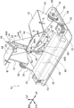
図1~図5を用いて本発明の実施形態に係る足首及び足指の機能訓練装置10について説明する。なお、足首及び足指の機能訓練装置10の前後方向前方側を矢印FRで示し、右側及び左側をそれぞれ矢印RH及び矢印LHで示し、上下方向上側を矢印UPで示す。また、以下の説明で、単に前後、左右、上下の方向を示す場合は、足首及び足指の機能訓練装置10の前後、左右、上下を示すものとする。
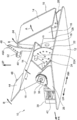
図1~図4に示されるように、本実施形態の足首及び足指の機能訓練装置10は、使用者の両足が載せられた状態で作動されることで、当該使用者の足首のストレッチを行うための装置である。図3に示されるように、この足首及び足指の機能訓練装置10は、床等に載置されるベース部12を備えている。このベース部12は、平面視で(上方側から見て)左右方向を長手方向とする矩形板状に形成されている。
また、足首及び足指の機能訓練装置10は、使用者の足が載せられ、当該使用者の足の後足部から前足部にかけての部分と対向して配置される左右一対の足載せ部14を備えている。足載せ部14は、使用者の足の後足部から前足部にかけての方向を長手方向とする矩形板状に形成されている。足載せ部14の左右の両端部には、側面視(右側又は左側から見て)で三角形状に形成された一対の側壁板16が固定されている。なお、左右の側壁板16は、左右方向を厚み方向として互いに平行に延びている。
図1及び図2に示されるように、左側の足載せ部14に固定された左側の側壁板16には、左右方向を軸方向とする回転軸18が固定されている。また、図3に示されるように、左側の足載せ部14に固定された右側の側壁板16には、左右方向を軸方向とする回転軸20が挿通されている。図2及び図3に示されるように、この回転軸20には、側面視で略扇状に形成されていると共に左側の足載せ部14に固定された右側の側壁板16に沿って配置された傾動角度制限板22が固定されている。傾動角度制限板22には、ピン24が挿通される複数のピン挿通孔22Aが形成されていると共に、左側の足載せ部14に固定された右側の側壁板16には、ピン24が挿通される図示しないピン挿通孔が形成されている。そして、ピン24が、傾動角度制限板22(ピン挿通孔22A)及び左側の足載せ部14に固定された右側の側壁板16(図示しないピン挿通孔)に係合した状態では、傾動角度制限板22と左側の足載せ部14に固定された右側の側壁板16とが、回転軸20を軸中心として一体に変位(傾動)するようになっている。そして、左側の足載せ部14に固定された右側の側壁板16と一体に変位した傾動角度制限板22がベース部12に当接することで、左側の足載せ部14の背屈方向(矢印A方向)への傾動が制限されるようになっている。なお、複数のピン挿通孔22Aへのピン24の挿通位置を変更することで、左側の足載せ部14の背屈方向への傾動角度の最大角度を調節することが可能となっている。
また、右側の足載せ部14に固定された右側の側壁板16には、左右方向を軸方向とする回転軸18が固定されている。また、右側の足載せ部14に固定された左側の側壁板16には、左右方向を軸方向とする回転軸20が挿通されており、この回転軸20には、傾動角度制限板22が固定されている。なお、右側の足載せ部14に固定された左側の側壁板16と傾動角度制限板22との関係は、前述の左側の足載せ部14に固定された右側の側壁板16と傾動角度制限板22との関係と同一である。
図3に示されるように、足首及び足指の機能訓練装置10の左右方向の中央側に配置された回転軸20は、後述するギヤボックス28に回転可能に支持されている。また、足首及び足指の機能訓練装置10の左右方向の両側に配置された回転軸18は、ベース部12に固定された支持板26に回転可能に支持されている。これにより、足載せ部14が、回転軸18、20を軸中心として背屈方向及び底屈方向(上下方向)に傾動(回動)するようになっている。
また、左右の足載せ部14の間には、箱状のギヤボックス28が設けられており、このギヤボックス28は、ベース部12に固定されている。ギヤボックス28に支持された2つの回転軸20には、かさ歯車30がそれぞれ固定されている。また、一方の回転軸20に固定されたかさ歯車30と他方の回転軸20に固定されたかさ歯車30とは、前後方向を軸方向としてギヤボックス28に回転可能に支持されたかさ歯車32を介してつながれている。これにより、図2及び図3に示されるように、傾動角度制限板22と足載せ部14に固定された側壁板16とが、ピン24を介して一体に変位可能とされている状態では、一方の回転軸20の回転が、かさ歯車30、32を介して他方の回転軸20に反対方向への回転として伝達されるようになっている。これにより、左右の足載せ部14が交互に傾動されるようになっている。すなわち、右側の足載せ部14が上方側へ傾動される際には、左側の足載せ部14が下方側へ傾動され、左側の足載せ部14が上方側へ傾動される際には、右側の足載せ部14が下方側へ傾動されるようになっている。
また、傾動角度制限板22と足載せ部14に固定された側壁板16とが、ピン24を介してつながれていない状態(ピン24が外された状態)では、一方の回転軸20の回転が、かさ歯車30、32を介して他方の回転軸20に伝達されない。これにより、左右の足載せ部14を独立して傾動させることが可能となっている。
図1及び図3に示されるように、左右の支持板26にそれぞれ支持された2つの回転軸18には、ワイヤ34が係止されるプーリ36が固定されている。そして、後述する人工筋肉40が収縮してワイヤ34が引かれることで、プーリ36が回転するようになっている。これにより、ワイヤ34が引かれた側の足載せ部14が、背屈方向(矢印A方向)へ傾動されるようになっている。なお、図1以外の図においては、ワイヤ34の図示を省略している。
ベース部12の前端部には、左右方向を長手方向とする箱状に形成された人工筋肉支持ボックス38が固定されている。この人工筋肉支持ボックス38の内部には、左右方向に平行に配置されたアクチュエータとしての2つの人工筋肉40が配置されている。ここで、本実施形態の人工筋肉40は、所謂McKibben型の人工筋肉である。この人工筋肉40は、ゴム等の弾性材料を用いて管状に形成された弾性チューブと、弾性チューブを覆う筒状のメッシュスリーブと、を含んで構成されており、弾性チューブをメッシュスリーブで被覆して両端をかしめた構造となっている。そして、弾性チューブ内にガス(空気)が供給されることで、人工筋肉40が左右方向に収縮するようになっている。
2つの人工筋肉40のうち後方側に配置された人工筋肉40の右側の端部は人工筋肉支持ボックス38に係止されており、左側の端部はワイヤ34を介して左側のプーリ36に繋がれている。また、2つの人工筋肉40のうち前方側に配置された人工筋肉40の左側の端部は人工筋肉支持ボックス38に係止されており、右側の端部はワイヤ34を介して右側のプーリ36に繋がれている。なお、ワイヤ34における人工筋肉40とプーリ36との間の中間部は、ベース部12に上下方向を軸方向として回転可能に支持されたガイドプーリ42によってガイドされることでL字状に曲げられている。
図1に示されるように、左右の足載せ部14の前端部には、足載せ部14と同様に板状に形成されていると共に使用者の足の指と対向して配置される足指載せ部44がそれぞれ取付けられている。この足指載せ部44は、足載せ部14に図示しない蝶番を介して取付けられることで当該足載せ部14に対して左右方向を軸方向として上下方向に傾動可能となっている。
左右の足指載せ部44における左右の中央側の端部には、後述する足指伸展リンク48が係合するリンク係合部46がそれぞれ固定されている。このリンク係合部46には、後述するピン52が挿通されるピン挿通孔46Aが形成されている。なお、リンク係合部46は足指載せ部44の一部に含まれるものとする。また、足指載せ部44とリンク係合部46とを一体に形成してもよい。そして、左側のリンク係合部46とギヤボックス28とは、接続部材としての足指伸展リンク48を介してつながれていると共に、右側のリンク係合部46とギヤボックス28とは、足指伸展リンク48を介してつながれている。
足指伸展リンク48は、左右方向を厚み方向とする板状に形成されている。この足指伸展リンク48の一方側の端部は、左右方向を軸方向とするピン50を介してギヤボックス28に傾動(回動)可能に支持されている。また、足指伸展リンク48の他方側の端部は、略T字状に形成されており、この足指伸展リンク48の他方側の端部には、複数のピン挿通孔48Aが形成されている。そして、足指伸展リンク48のピン挿通孔48A及びリンク係合部46のピン挿通孔46Aにピン52が挿通されることで、足指伸展リンク48の他方側の端部がリンク係合部46に係合するようになっている。そして、この足指伸展リンク48を有することで、足載せ部14が底屈方向(矢印Aとは反対方向)へ傾動された際に、足指載せ部44を足載せ部14に対して伸展方向(矢印B方向)へ傾倒させることが可能となっている。また、足載せ部14が背屈方向(矢印A方向)へ傾動された際に、足指載せ部44を足載せ部14に対して屈曲方向(矢印Bとは反対方向)へ傾倒させることが可能となっている。ここで、本実施形態では、足指伸展リンク48に形成された複数のピン挿通孔48Aへのピン52の挿通位置を変更することで、足載せ部14が傾動された際における足指載せ部44の足載せ部14に対する傾倒角度を調節することが可能となっている。
図5に示されるように、本実施形態の足首及び足指の機能訓練装置10では、使用者の足を足載せ部14に載せた状態に保持させるための保持部材54が当該足載せ部14に固定されている。この保持部材54は、足載せ部14及び足指載せ部44に沿って配置されると共に使用者の足の踵が係止可能とされた底面部54Aと、使用者の足首等に巻回されるベルト部54B等を含んで構成されている。なお、保持部材54としては、市販のサンダル等を用いることもできる。
(本実施形態の作用並びに効果)
次に、本実施形態の作用並びに効果について説明する。
次に、本実施形態の作用並びに効果について説明する。
先ず、図2に示された傾動角度制限板22と足載せ部14に固定された側壁板16とが、ピン24を介して一体に変位可能とされている状態で本実施形態の足首及び足指の機能訓練装置10が使用された場合の作用並びに効果について説明する。
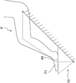
図1及び図5に示されるように、使用者の足が保持部材54によって保持された状態において、2つの人工筋肉40のうち前方側に配置された人工筋肉40が収縮すると、右側の足載せ部14が、背屈方向(矢印A方向)へ傾動されると共に、足指載せ部44が足載せ部14に対して屈曲方向(矢印Bとは反対方向)へ傾倒される。これに伴い、右側の足載せ部14が、底屈方向(矢印Aとは反対方向)へ傾動されると共に、足指載せ部44が足載せ部14に対して伸展方向(矢印B方向)へ傾倒される。これにより、図6に示されるように、使用者の左足P1を底屈させることができると共に左足の指を伸展させることができる。なお、図6においては、左足P1の指の伸展は反映されていない。また、使用者の右足を背屈させることができる。
また、2つの人工筋肉40のうち後方側に配置された人工筋肉40が収縮すると、左側の足載せ部14が、背屈方向(矢印A方向)へ傾動されると共に、足指載せ部44が足載せ部14に対して屈曲方向(矢印Bとは反対方向)へ傾倒される。これに伴い、右側の足載せ部14が、底屈方向(矢印Aとは反対方向)へ傾動されると共に、足指載せ部44が足載せ部14に対して伸展方向(矢印B方向)へ傾倒される。これにより、使用者の右足を底屈させることができる。また、図7に示されるように、使用者の左足P1を背屈させることができる。
そして、2つの人工筋肉40を交互に収縮させることで、左右の足載せ部14及び足指載せ部44を上記のように交互に動かすことができる。これにより、使用者の下肢Pを歩行時を模擬した状態(4節回転リンクを模擬した状態)で可動させることができる。
以上説明したように、本実施形態では、足の指を伸展させることができることにより、足首及び足指の機能訓練装置10の使用効果を向上させることができる。特に、足の指の伸展を伴う歩行を模擬して使用者の下肢Pを稼働させることができることにより、歩行のリハビリテーションを効果的に行うことができる。また、足首が曲がった状態となっている使用者が、踵を保持部材54の底面部54Aに押し付けるようにした状態で、本実施形態の足首及び足指の機能訓練装置10を用いることにより、歩行のリハビリテーションを効果的に行うことができる。
また、本実施形態では、足指伸展リンク48に形成された複数のピン挿通孔48Aへのピン52の挿通位置を変更することで、足載せ部14が傾動された際における足指載せ部44の足載せ部14に対する傾倒角度を調節することができる。これにより、足の指の伸展に伴う負荷を容易に調節することができる。
さらに、本実施形態では、図2に示された傾動角度制限板22に形成された複数のピン挿通孔22Aへのピン24の挿通位置を変更することで、足載せ部14の背屈方向への傾動角度の最大角度を調節することができる。これにより、足の背屈に伴う負荷を容易に調節することができる。
次に、傾動角度制限板22と足載せ部14に固定された側壁板16とが、ピン24を介して一体に変位可能とされていない状態(ピン24が外された状態)で本実施形態の足首及び足指の機能訓練装置10が使用された場合の作用並びに効果について説明する。
この場合においては、2つの人工筋肉40のうち後方側に配置された人工筋肉40が収縮すると、左側の足載せ部14が、背屈方向(矢印A方向)へ傾動されると共に、足指載せ部44が足載せ部14に対して屈曲方向(矢印Bとは反対方向)へ傾倒される。この時、右側の足載せ部14及び足指載せ部44は傾動しない。
また、2つの人工筋肉40のうち前方側に配置された人工筋肉40が収縮すると、右側の足載せ部14が、背屈方向(矢印A方向)へ傾動されると共に、足指載せ部44が足載せ部14に対して屈曲方向(矢印Bとは反対方向)へ傾倒される。この時、左側の足載せ部14及び足指載せ部44は傾動しない。
さらに、2つの人工筋肉40の両方が同時に収縮すると、左右の足載せ部14が、背屈方向(矢印A方向)へ同時に傾動されると共に、左右の足指載せ部44が足載せ部14に対して屈曲方向(矢印Bとは反対方向)へ同時に傾倒される。
このように、ピン24が外された状態では、使用者の左右の足を独立して自在に稼働させることができる。
ここで、本実施形態では、足載せ部14及び足指載せ部44を傾動させるためのアクチュエータとして人工筋肉40を採用している。これにより、足載せ部14から使用者の足に加わる衝撃を人工筋肉40の内部のガスにより緩和することができる。
また、人工筋肉40は、単位質量及び単位体積当たりの出力が大きいアクチュエータであるため、足首及び足指の機能訓練装置10の小型化及び軽量化を図ることができる。図8には、アクチュエータとしてモータ58が用いられた本発明の他の実施形態に係る足首及び足指の機能訓練装置56が示されている。この足首及び足指の機能訓練装置56の足載せ部14及び足指載せ部44を傾動させる力は、前述の足首及び足指の機能訓練装置10と同じではあるが、足首及び足指の機能訓練装置56の体格(特に左右方向への体格)は、前述の足首及び足指の機能訓練装置10よりも大型化していることがわかる。また、足首及び足指の機能訓練装置56の質量も、前述の足首及び足指の機能訓練装置10よりも増加している。なお、足載せ部14及び足指載せ部44を傾動させるアクチュエータは、足首及び足指の機能訓練装置が使用される環境等を考慮して適宜選択すればよい。
以上、本発明の一実施形態について説明したが、本発明は、上記に限定されるものでなく、その主旨を逸脱しない範囲内において上記以外にも種々変形して実施することが可能であることは勿論である。
Claims (6)
- 使用者の足が載せられ、該使用者の足の後足部から前足部にかけての部分と対向して配置される足載せ部と、
作動されることで、前記足載せ部を変位させるアクチュエータと、
前記使用者の足が前記足載せ部に載せられた状態で、前記使用者の足の指と対向して配置され、前記アクチュエータが作動されて前記足載せ部が変位される際に、該足載せ部に対して変位される足指載せ部と、
を備えた足首及び足指の機能訓練装置。 - 前記足載せ部が、前記使用者の足を底屈させる方向へ変位される際に、前記足指載せ部が、前記足載せ部に対して前記使用者の足の指を伸展させる方向へ変位される請求項1記載の足首及び足指の機能訓練装置。
- 左右一対の前記足載せ部及び左右一対の前記足指載せ部を備え、
前記アクチュエータが作動されることで、左右一対の前記足載せ部が左右交互に変位する請求項1又は請求項2記載の足首及び足指の機能訓練装置。 - 前記足載せ部は、ベース部に支持されており、
前記足指載せ部と前記ベース部との間には、接続部材が設けられ、
前記足指載せ部と前記接続部材との接続位置が変更されることで、前記足載せ部が変位される際における前記足指載せ部の前記足載せ部に対する変位量が調節される請求項1~請求項3のいずれか1項に記載の足首及び足指の機能訓練装置。 - 前記アクチュエータは、内部にガスが供給されることで収縮する人工筋肉とされている請求項1~請求項4のいずれか1項に記載の足首及び足指の機能訓練装置。
- 前記使用者の足の踵が係止可能とされた保持部材が、前記足載せ部に固定されている請求項1~請求項5のいずれか1項に記載の足首及び足指の機能訓練装置。
Priority Applications (3)
| Application Number | Priority Date | Filing Date | Title |
|---|---|---|---|
| CN201980011674.2A CN111683637A (zh) | 2018-02-05 | 2019-01-23 | 脚踝及脚趾的功能训练装置 |
| EP19746688.1A EP3738573A4 (en) | 2018-02-05 | 2019-01-23 | ANKLE AND TOE FUNCTION TRAINING DEVICE |
| US16/967,532 US20210212878A1 (en) | 2018-02-05 | 2019-01-23 | Ankle and toe function training device |
Applications Claiming Priority (2)
| Application Number | Priority Date | Filing Date | Title |
|---|---|---|---|
| JP2018018456A JP2019134889A (ja) | 2018-02-05 | 2018-02-05 | 足首及び足指の機能訓練装置 |
| JP2018-018456 | 2018-02-05 |
Publications (1)
| Publication Number | Publication Date |
|---|---|
| WO2019151086A1 true WO2019151086A1 (ja) | 2019-08-08 |
Family
ID=67479211
Family Applications (1)
| Application Number | Title | Priority Date | Filing Date |
|---|---|---|---|
| PCT/JP2019/002124 Ceased WO2019151086A1 (ja) | 2018-02-05 | 2019-01-23 | 足首及び足指の機能訓練装置 |
Country Status (5)
| Country | Link |
|---|---|
| US (1) | US20210212878A1 (ja) |
| EP (1) | EP3738573A4 (ja) |
| JP (1) | JP2019134889A (ja) |
| CN (1) | CN111683637A (ja) |
| WO (1) | WO2019151086A1 (ja) |
Cited By (1)
| Publication number | Priority date | Publication date | Assignee | Title |
|---|---|---|---|---|
| CN112022648A (zh) * | 2020-09-02 | 2020-12-04 | 华侨大学 | 一种以前端伸缩按摩脚趾的康复训练装置 |
Families Citing this family (2)
| Publication number | Priority date | Publication date | Assignee | Title |
|---|---|---|---|---|
| US12539445B2 (en) * | 2015-06-01 | 2026-02-03 | Richard Duenas | Squat and spinal fitness and rehabilitation device |
| CN111012622B (zh) * | 2019-11-27 | 2025-06-20 | 合肥工业大学 | 训练装置 |
Citations (8)
| Publication number | Priority date | Publication date | Assignee | Title |
|---|---|---|---|---|
| US4862875A (en) * | 1987-03-31 | 1989-09-05 | Samuel Heaton | Leg exercisers |
| US5267924A (en) * | 1993-01-07 | 1993-12-07 | Advanced Kinetics, Inc. | Apparatus and method for imparting continuous passive motion to the foot |
| JP2000342714A (ja) * | 1999-06-07 | 2000-12-12 | Yoshihiro Kimura | 椅子に腰掛けて足首、足指を屈伸する運動具 |
| JP2002143269A (ja) * | 2000-11-08 | 2002-05-21 | Shinko Denshi Kk | 足首・足指運動用健康器 |
| WO2004085856A1 (ja) * | 2003-03-25 | 2004-10-07 | Hitachi Medical Corporation | 流体圧式アクチュエータ及びそれを用いた持続的他動運動装置 |
| WO2009122480A1 (ja) * | 2008-03-31 | 2009-10-08 | パナソニック電工株式会社 | 運動装置 |
| US20100241037A1 (en) * | 2006-08-25 | 2010-09-23 | Thomas Pete G | Continuous passive motion device for a toe |
| JP2017169684A (ja) | 2016-03-22 | 2017-09-28 | 株式会社エヌエステイー | 足首ストレッチ装置 |
Family Cites Families (4)
| Publication number | Priority date | Publication date | Assignee | Title |
|---|---|---|---|---|
| JP4085422B2 (ja) * | 2002-09-04 | 2008-05-14 | 株式会社安川電機 | 関節駆動装置 |
| KR101232938B1 (ko) * | 2005-12-28 | 2013-02-13 | 에이코 엔터프라이즈 가부시키가이샤 | 발가락 마사지 장치 |
| EP2815793B1 (de) * | 2013-06-17 | 2018-09-05 | schepp medtech GmbH | Gangbewegungsvorrichtung |
| KR101600600B1 (ko) * | 2013-11-20 | 2016-03-08 | 조재민 | 족부 스트레칭 장치 |
-
2018
- 2018-02-05 JP JP2018018456A patent/JP2019134889A/ja active Pending
-
2019
- 2019-01-23 CN CN201980011674.2A patent/CN111683637A/zh active Pending
- 2019-01-23 EP EP19746688.1A patent/EP3738573A4/en not_active Withdrawn
- 2019-01-23 US US16/967,532 patent/US20210212878A1/en not_active Abandoned
- 2019-01-23 WO PCT/JP2019/002124 patent/WO2019151086A1/ja not_active Ceased
Patent Citations (8)
| Publication number | Priority date | Publication date | Assignee | Title |
|---|---|---|---|---|
| US4862875A (en) * | 1987-03-31 | 1989-09-05 | Samuel Heaton | Leg exercisers |
| US5267924A (en) * | 1993-01-07 | 1993-12-07 | Advanced Kinetics, Inc. | Apparatus and method for imparting continuous passive motion to the foot |
| JP2000342714A (ja) * | 1999-06-07 | 2000-12-12 | Yoshihiro Kimura | 椅子に腰掛けて足首、足指を屈伸する運動具 |
| JP2002143269A (ja) * | 2000-11-08 | 2002-05-21 | Shinko Denshi Kk | 足首・足指運動用健康器 |
| WO2004085856A1 (ja) * | 2003-03-25 | 2004-10-07 | Hitachi Medical Corporation | 流体圧式アクチュエータ及びそれを用いた持続的他動運動装置 |
| US20100241037A1 (en) * | 2006-08-25 | 2010-09-23 | Thomas Pete G | Continuous passive motion device for a toe |
| WO2009122480A1 (ja) * | 2008-03-31 | 2009-10-08 | パナソニック電工株式会社 | 運動装置 |
| JP2017169684A (ja) | 2016-03-22 | 2017-09-28 | 株式会社エヌエステイー | 足首ストレッチ装置 |
Non-Patent Citations (1)
| Title |
|---|
| See also references of EP3738573A4 * |
Cited By (2)
| Publication number | Priority date | Publication date | Assignee | Title |
|---|---|---|---|---|
| CN112022648A (zh) * | 2020-09-02 | 2020-12-04 | 华侨大学 | 一种以前端伸缩按摩脚趾的康复训练装置 |
| CN112022648B (zh) * | 2020-09-02 | 2024-05-17 | 华侨大学 | 一种以前端伸缩按摩脚趾的康复训练装置 |
Also Published As
| Publication number | Publication date |
|---|---|
| JP2019134889A (ja) | 2019-08-15 |
| EP3738573A1 (en) | 2020-11-18 |
| US20210212878A1 (en) | 2021-07-15 |
| EP3738573A4 (en) | 2021-04-14 |
| CN111683637A (zh) | 2020-09-18 |
Similar Documents
| Publication | Publication Date | Title |
|---|---|---|
| JP4816795B2 (ja) | 他動運動機器 | |
| JP4936180B2 (ja) | 他動運動機器 | |
| JP4656178B2 (ja) | 他動運動装置 | |
| KR20170003163U (ko) | 보행식 운동기 | |
| JPWO2016140167A1 (ja) | 足用マッサージ装置 | |
| JP7002717B2 (ja) | 下肢の自動運動用装置 | |
| JP5054780B2 (ja) | 運動補助装置 | |
| TW200934553A (en) | Standing-position type passive exercise machine | |
| JP5713388B2 (ja) | 膝関節運動補助装置 | |
| WO2009081935A1 (ja) | 運動補助装置 | |
| JP2019134889A (ja) | 足首及び足指の機能訓練装置 | |
| JP2022098659A (ja) | 足漕ぎ運動機器 | |
| JP5032838B2 (ja) | 運動補助装置 | |
| WO2011105411A1 (ja) | 運動補助装置 | |
| CN112739301A (zh) | 用于执行振动训练的具有可调节的手柄的设备 | |
| JP2019177055A (ja) | 足関節・足部の運動支援装置 | |
| KR101595535B1 (ko) | 발끝치기 운동장치 | |
| JP2004181163A (ja) | 足首運動器 | |
| JP7160419B1 (ja) | 訓練装置 | |
| WO2009122480A1 (ja) | 運動装置 | |
| JP2012020050A (ja) | 股関節運動装置 | |
| JP5091623B2 (ja) | 他動運動機器 | |
| JP2025055658A (ja) | 運動装置 | |
| JP6083502B2 (ja) | 簡潔構造の人間型足構造 | |
| JP2012152301A (ja) | 運動補助装置 |
Legal Events
| Date | Code | Title | Description |
|---|---|---|---|
| 121 | Ep: the epo has been informed by wipo that ep was designated in this application |
Ref document number: 19746688 Country of ref document: EP Kind code of ref document: A1 |
|
| NENP | Non-entry into the national phase |
Ref country code: DE |
|
| ENP | Entry into the national phase |
Ref document number: 2019746688 Country of ref document: EP Effective date: 20200811 |