WO2019155593A1 - 部品画像認識用学習済みモデル作成システム及び部品画像認識用学習済みモデル作成方法 - Google Patents
部品画像認識用学習済みモデル作成システム及び部品画像認識用学習済みモデル作成方法 Download PDFInfo
- Publication number
- WO2019155593A1 WO2019155593A1 PCT/JP2018/004555 JP2018004555W WO2019155593A1 WO 2019155593 A1 WO2019155593 A1 WO 2019155593A1 JP 2018004555 W JP2018004555 W JP 2018004555W WO 2019155593 A1 WO2019155593 A1 WO 2019155593A1
- Authority
- WO
- WIPO (PCT)
- Prior art keywords
- component
- learned model
- image recognition
- learned
- image
- Prior art date
- Legal status (The legal status is an assumption and is not a legal conclusion. Google has not performed a legal analysis and makes no representation as to the accuracy of the status listed.)
- Ceased
Links
Images
Classifications
-
- G—PHYSICS
- G06—COMPUTING OR CALCULATING; COUNTING
- G06T—IMAGE DATA PROCESSING OR GENERATION, IN GENERAL
- G06T7/00—Image analysis
- G06T7/0002—Inspection of images, e.g. flaw detection
- G06T7/0004—Industrial image inspection
- G06T7/0008—Industrial image inspection checking presence/absence
-
- G—PHYSICS
- G06—COMPUTING OR CALCULATING; COUNTING
- G06F—ELECTRIC DIGITAL DATA PROCESSING
- G06F18/00—Pattern recognition
- G06F18/20—Analysing
- G06F18/21—Design or setup of recognition systems or techniques; Extraction of features in feature space; Blind source separation
- G06F18/214—Generating training patterns; Bootstrap methods, e.g. bagging or boosting
- G06F18/2155—Generating training patterns; Bootstrap methods, e.g. bagging or boosting characterised by the incorporation of unlabelled data, e.g. multiple instance learning [MIL], semi-supervised techniques using expectation-maximisation [EM] or naïve labelling
-
- G—PHYSICS
- G06—COMPUTING OR CALCULATING; COUNTING
- G06T—IMAGE DATA PROCESSING OR GENERATION, IN GENERAL
- G06T7/00—Image analysis
- G06T7/0002—Inspection of images, e.g. flaw detection
- G06T7/0004—Industrial image inspection
- G06T7/001—Industrial image inspection using an image reference approach
-
- H—ELECTRICITY
- H05—ELECTRIC TECHNIQUES NOT OTHERWISE PROVIDED FOR
- H05K—PRINTED CIRCUITS; CASINGS OR CONSTRUCTIONAL DETAILS OF ELECTRIC APPARATUS; MANUFACTURE OF ASSEMBLAGES OF ELECTRICAL COMPONENTS
- H05K13/00—Apparatus or processes specially adapted for manufacturing or adjusting assemblages of electric components
- H05K13/08—Monitoring manufacture of assemblages
-
- G—PHYSICS
- G06—COMPUTING OR CALCULATING; COUNTING
- G06T—IMAGE DATA PROCESSING OR GENERATION, IN GENERAL
- G06T2207/00—Indexing scheme for image analysis or image enhancement
- G06T2207/20—Special algorithmic details
- G06T2207/20081—Training; Learning
-
- G—PHYSICS
- G06—COMPUTING OR CALCULATING; COUNTING
- G06T—IMAGE DATA PROCESSING OR GENERATION, IN GENERAL
- G06T2207/00—Indexing scheme for image analysis or image enhancement
- G06T2207/30—Subject of image; Context of image processing
- G06T2207/30108—Industrial image inspection
- G06T2207/30148—Semiconductor; IC; Wafer
Definitions
- the present invention discloses a technique related to a learned model creation system for image recognition and a learned model creation method for component image recognition.
- a component mounter is equipped with a camera that captures the component sucked by the suction nozzle, and by processing the image captured by the camera, Whether the suction posture of the component is normal suction or abnormal suction is determined, the component determined to be abnormal suction is discarded, and only the component determined to be normal suction is mounted on the circuit board.
- normal suction / abnormal suction is determined using image processing component shape data including the size of the component, etc., but the component sucked by the suction nozzle is a minute component. In some cases, it may be difficult to discriminate between normal suction and abnormal suction in image processing using conventional image processing component shape data.
- Patent Document 1 Japanese Patent Laid-Open No. 2008-130865
- a learned model for discriminating normal adsorption / abnormal adsorption is created in advance using a machine learning technique such as a neural network.
- a component image captured by a camera of a component mounting machine is processed during production, and normal adsorption / abnormal adsorption is determined using a learned model.
- parts that have the same electrical specifications may differ in size, color, material, manufacturing company, manufacturing lot, etc., and differences in image recognition results may occur due to these differences. is there.
- the types of parts are subdivided according to size, color, material, manufacturing company, manufacturing lot, etc., and all types are learned by machine learning techniques. Therefore, it is necessary to create a large number of trained models, and it takes a lot of time and effort to create a trained model.
- the computer includes a computer that acquires a reference learned model used for image recognition of a reference component, and the computer has a predetermined similarity relationship with the reference component
- a sample part image is collected for each part type, and the sample part image is added as teacher data of the reference learned model for each part type, and re-learned.
- a part-learned model used for image recognition is created.
- sample part images are collected for each type of the part, and the sample part is collected for each type of the part.
- a learned model for each component used for image recognition of the component is created for each type of the component. In this way, a part-by-part learned model used for image recognition of a part having a predetermined similarity to the reference part can be created relatively easily from the reference learned model.
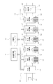
- FIG. 1 is a block diagram illustrating a configuration example of a component mounting line according to an embodiment.
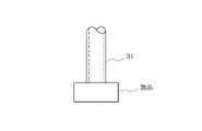
- FIG. 2 is a front view for explaining normal adsorption.
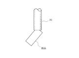
- FIG. 3 is a front view illustrating oblique suction.
- FIG. 4 is a flowchart showing the flow of processing of the component suction posture determination program.
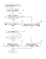
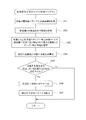
- FIG. 5 is a flowchart showing the flow of processing of the part-by-part learned model creation program.
- the component mounting line 10 includes one or a plurality of component mounting machines 12 and mounting related machines such as a solder printer 13 and a flux application device (not shown) arranged in the conveyance direction of the circuit board 11. It is configured. On the board carry-out side of the component mounting line 10, an inspection machine 14 for inspecting the quality of the mounted state of each component mounted on the circuit board 11 is installed.
- Each component mounting machine 12, solder printing machine 13, and inspection machine 14 of the component mounting line 10 are connected to a production management computer 21 via a network 16 so that they can communicate with each other. Ten productions are managed.
- the control device 17 of each component mounting machine 12 is mainly composed of one or a plurality of computers (CPUs), and is mounted according to a production job (production program) transferred from the production management computer 21 (not shown). 1) is moved along the path of the component suction position ⁇ the component imaging position ⁇ the component mounting position, and the component (see FIGS. 2 and 3) supplied from the feeder 19 is moved to the suction nozzle 31 (see FIGS. 2 and 3) of the mounting head.
- the control device 20 of the inspection machine 14 is mainly composed of one or a plurality of computers (CPUs), and the mounting state of each component on the circuit board 11 carried in is picked up by the inspection camera 22 from above. Then, the captured image is processed to recognize the presence / absence of each component on the circuit board 11 and the mounting state such as mounting position deviation, and the presence / absence of mounting failure (inspection failure) of each component based on the recognition result Inspect. At this time, the presence or absence of each component on the circuit board 11 may be determined using a learned model described later.
- the network 16 of the component mounting line 10 is connected to a learning computer 23 that collects and learns teacher data (sample component images) used for creating a reference learned model and a learned model for each component described later.
- the control device 17 of each component mounting machine 12 selects a learned model according to the type of component sucked by the suction nozzle 31 by executing a component suction posture determination program of FIG. Whether or not the suction posture of the component is normal suction or abnormal suction is determined from the processing result of the captured image of the component, and the captured image determined to be normal suction is transferred to the learning computer 23 as a normal suction sample component image. The captured image determined to be suction is transferred to the learning computer 23 as a sample part image for abnormal suction.
- the learning computer 23 executes a part-by-part learned model creation program shown in FIG. 5 to be described later, whereby normal suction / abnormal suction sample part images transferred from the control device 17 of each component mounting machine 12 are obtained.
- the components are classified and collected for each type of component, and the information on the inspection result of the inspection machine 14 is acquired to calculate the mounting defect occurrence rate for each component type.
- the normal suction / abnormal suction sample part image collected for the part is added as the teacher data of the reference learned model and re-learned to learn the model for each part used for image recognition , And transfer the learned model for each component to the control device 17 of each component mounter 12.
- the relearning method may be a machine learning method such as a neural network or a support vector machine.
- the reference learned model is a learned model used for image recognition of a reference component
- the learning computer 23 collects sample component images of normal suction / abnormal suction of the reference component as teacher data. Then, a reference learned model may be created by learning by machine learning such as a neural network or a support vector machine, or a reference learned model created by an external computer may be taken into the learning computer 23.
- the reference component is not limited to a specific component, and a component for which a learned model has been created in advance may be used as a “reference component”.
- the control device 17 of each component mounter 12 associates the reference learned model and the component-specific learned model transferred from the learning computer 23 with the type of component that recognizes an image using the model (not shown).
- the reference learned model or the part-learned model is included in the image processing part shape data prepared for each part type and stored.
- the term “learned model” includes both a reference learned model and a part-by-part learned model.
- Image processing component shape data is data representing the appearance characteristics such as the size of the body part of the component, the position of the terminals such as bumps and leads, size, pitch, and number, and identifies the type of the component that has been image-recognized. It is used to measure the suction position and angle of parts.
- the process of including the learned model created for each component type in the image processing component shape data prepared for each component type may be performed by the control device 17 of each component mounter 12, or for learning. You may perform with computer 23. Alternatively, the learned model is transferred from the learning computer 23 to the production management computer 21, and the production management computer 21 performs processing for including the learned model in the image processing part shape data.
- the image processing component shape data including the learned model may be transferred from the computer 21 to the control device 17 of each component mounter 12.
- the control device 17 of each component mounting machine 12 uses a learned model used for image recognition of a component sucked by the suction nozzle 31 in the learned model stored for each type of component. If the learned model for the component does not exist, the component adsorbed by the adsorption nozzle 31 is selected from the components in which the learned model exists. A part having a predetermined similarity is regarded as a “reference part”, and a learned model for the reference part is used as a “reference learned model” to recognize an image of the part adsorbed on the suction nozzle 31. Do.
- the learned model for the reference part may be a part-by-part learned model created from the reference learned model for other parts. In this case, the reference learned model for other parts The part-by-part learned model created from the above is used as the reference learned model.
- the parts having a predetermined similarity relationship are, for example, parts having the same or similar shape even if the part size, color, material, manufacturing company, manufacturing lot, etc. are different. . If there is a predetermined similarity between the parts, the image with a certain degree of accuracy (generally more than the minimum necessary for production) can be obtained even if image recognition of the other part is performed using the learned model for one part. Recognizable. In other words, if image recognition of the other component can be performed with a certain degree of accuracy using the learned model for one component, it can be said that these two components have a predetermined similarity.
- Part suction attitude discrimination program The component suction posture determination program shown in FIG. 4 is executed by the control device 17 of each component mounting machine 12 every time when the component picked up by the suction nozzle 31 of each component mounting machine 12 is imaged by the component imaging camera 18 during production. Executed.
- step 101 the component sucked by the suction nozzle 31 is imaged by the component imaging camera 18, and the captured image is captured. Thereafter, the process proceeds to step 102, where it is determined whether or not a learned model for the imaged part exists among the learned models stored for each type of part in a storage device (not shown). If there is a learned model for the imaged part, the process proceeds to step 103, and the learned model for the imaged part is selected as the learned model used for the current image recognition.
- step 104 the process proceeds to step 104 and stored in the storage device for each type of component.
- a learned model for a component having a predetermined similarity with the imaged component is selected as a learned model to be used for the current image recognition from the learned models.
- step 105 the current captured image is processed by the image processing function of the control device 17, and the selected learned model is used. Then, it is determined whether the picked-up posture of the imaged component is normal suction (see FIG. 2) or abnormal suction (see FIG. 3).
- step 106 it is determined whether or not the determination result of the suction posture is normal suction. If it is normal suction, the process proceeds to step 107, and the learning computer 23 uses the current picked-up image as a normal suction sample part image. And exit this program. On the other hand, if the determination result of the suction posture is not normal suction but abnormal suction, the process proceeds to step 108, the current captured image is transferred to the learning computer 23 as a sample part image for abnormal suction, and this program is terminated. As a result, the learning computer 23 collects normal suction / abnormal suction sample component images from the control device 17 of each component mounter 12.
- control device 17 of each component mounting machine 12 may temporarily collect normal suction / abnormal suction sample component images. In this case, every time the control device 17 of each component mounter 12 collects a predetermined number of sample component images (or every time a predetermined period of time is collected), the sample component images collected so far are collectively transferred to the learning computer 23. Alternatively, every time a sample component image transfer request is output from the learning computer 23, the learning device 23 collectively collects the sample component images collected by the control device 17 of each component mounting machine 12 so far. You may make it forward to. Alternatively, the production management computer 21 may collect sample part images from the control device 17 of each component mounter 12 and transfer the sample part images from the production management computer 21 to the learning computer 23. . In any method, the learning computer 23 can finally collect sample part images.
- the learning model creation program for each part in FIG. 5 is repeatedly executed by the learning computer 23 at a predetermined cycle.
- the learning computer 23 starts this program, first, in step 201, normal suction / abnormal suction sample part images are collected for each part type from the control device 17 of each component mounting machine 12 or the production management computer 21. . Then, in the next step 202, information on the inspection result is acquired from the inspection machine 14.
- step 203 the sample part image obtained by imaging the part determined to be defective in mounting by the inspection machine 14 is discarded from the collected normal suction sample part images. This is because even if it is determined as normal suction, a component determined as a mounting failure by the inspection machine 14 may actually be abnormal suction. Note that the processing of step 203 is performed by the control device 17 of each component mounting machine 12 or the production management computer 21, and only an image obtained by imaging a component that has not been determined to be defective by the inspection machine 14 is a normal suction sample. You may make it collect with the computer 23 for learning as components images.
- step 204 the mounting defect occurrence rate is calculated for each type of component based on the information of the inspection result acquired from the inspection machine 14.
- step 205 it is determined whether there is a component for which the calculated mounting defect occurrence rate exceeds a predetermined determination threshold value, and there is no component for which the mounting failure occurrence rate exceeds the determination threshold value. Therefore, it is determined that the accuracy of image recognition using the selected learned model is ensured (it is not necessary to create a part-by-part learned model), and the program is terminated.
- step 206 the normal suction / abnormal suction sample part image collected for the part is added and re-learned as the teacher data of the reference learned model used for image recognition of the part. Create a part-by-part learned model for the part. Thereafter, the process proceeds to step 207, where the created model-by-component learned model is transferred to the control device 17 of each component mounter 12, and this program ends. As a result, the control device 17 of each component mounter 12 is in a state where image recognition can be performed using the component-specific learned model transferred from the learning computer 23.
- sample parts images are collected for each part type for parts having a predetermined similarity to the reference part for which the reference learned model has been created.
- a part-by-part learned model used for image recognition of the part is created for each part type. Therefore, it is possible to create a part-learned model used for image recognition of parts that have a predetermined similarity to the reference part from the reference learned model, and to create a learned model Can save time and effort.
- the part-learned model created for each part type is included in the image processing part shape data prepared for each part type.
- the part-by-part learned model may be managed independently without being associated with the image processing part shape data.
- the parts picked up by the pick-up nozzle 31 of each component mounting machine 12 during the production are picked up by the part image pickup camera 18, and the image is processed to determine whether the pick-up posture of the part is normal picking or abnormal. Since the picked-up image that has been determined to be suctioned and collected as a normal suction sample part image, and the imaged image that was determined to be suctioned abnormally is collected as a sample part image of abnormal suction, In addition, the images captured by the component imaging camera 18 can be collected as normal suction / abnormal suction sample part images, and the work of collecting the sample part images can be saved.
- the method of collecting the sample part image is not limited to the method of collecting during production.
- the normal suction part and the abnormal suction part adsorbed to the suction nozzle 31 of the component mounting machine 12 before the start of production are respectively provided. Images may be captured by the imaging camera 18, and the captured images may be collected as normal suction / abnormal suction sample part images.
- a normal imaging / abnormal adsorption sample part image captured by the imaging apparatus may be collected using a dedicated imaging apparatus that captures the sample part image. When a dedicated imaging device is used, it is possible to collect normal suction / abnormal suction sample part images before, during or after production.
- the normal part / abnormal part sample part image collected for the part is displayed as the part image. Since it is added and re-learned as the teacher data of the reference learned model used for recognition, the learned model for each part is created and transferred to the control device 17 of each component mounter 12 Each time a part with a mounting failure rate exceeding a predetermined threshold value occurs during production, it is possible to create a part-by-part trained model used for image recognition of the part. The accuracy of image recognition can be improved and the mounting defect occurrence rate can be reduced.
- the part-learned model may be created before the start of production or after the end of production.
- the part-learned model may be created when the number of collected normal / abnormally attracted sample part images exceeds a predetermined number.
- the learned model of the present embodiment is a learned model that determines whether the suction posture of the component sucked by the suction nozzle 31 is normal suction or abnormal suction. However, the presence / absence of the component sucked by the suction nozzle 31 is determined. It may be a learned model. In this case, an image captured by the component imaging camera 18 in a state where there is a component adsorbed by the suction nozzle 31 is collected as a sample component image with a component, and a component imaging camera in a state where there is no component adsorbed by the suction nozzle 31.
- the image captured in 18 is collected as a sample part image without a part, and the sample part image with / without a part classified for each type of the part is used as the teacher data of the reference learned model used for image recognition of the part. And re-learning to create a part-by-part learned model for the part for each type of the part. Also in this case, the sample part image may be collected using a dedicated imaging device.
- the control device 20 of the inspection machine 14 captures the mounting state of each component on the circuit board 11 carried in with the inspection camera 22, processes the captured image, and uses the learned model.
- the presence / absence of each component on the circuit board 11 is inspected, and a captured image determined to have a component is collected as a sample component image with a component, and a captured image determined to have no component is collected as a sample component image without a component.
- sample part image By adding and re-learning the sample part image with / without parts classified for each part type as teacher data of the reference learned model used for image recognition of the part, for each part type A part-learned model for each part may be created. Also in this case, the sample part image may be collected using a dedicated imaging device.
- the present invention can be variously modified within the scope not departing from the gist, such as changing the configuration of the component mounting line 10 or changing the processing contents and processing order of each program in FIGS. 4 and 5 as appropriate. Needless to say, this can be done.
Landscapes
- Engineering & Computer Science (AREA)
- Theoretical Computer Science (AREA)
- Physics & Mathematics (AREA)
- General Physics & Mathematics (AREA)
- Computer Vision & Pattern Recognition (AREA)
- Quality & Reliability (AREA)
- Data Mining & Analysis (AREA)
- Bioinformatics & Cheminformatics (AREA)
- Evolutionary Computation (AREA)
- Evolutionary Biology (AREA)
- General Engineering & Computer Science (AREA)
- Bioinformatics & Computational Biology (AREA)
- Artificial Intelligence (AREA)
- Life Sciences & Earth Sciences (AREA)
- Operations Research (AREA)
- Manufacturing & Machinery (AREA)
- Microelectronics & Electronic Packaging (AREA)
- Supply And Installment Of Electrical Components (AREA)
- Image Analysis (AREA)
Abstract
部品実装機(12)の吸着ノズル(31)に吸着した部品又は回路基板(11)に実装した部品を撮像対象とし、この撮像対象をカメラ(18,22)で撮像して画像認識する際に使用する学習済みモデルを作成する部品画像認識用学習済みモデル作成システムにおいて、基準となる部品の画像認識に使用する基準学習済みモデルを取得するコンピュータ(23)を備える。このコンピュータは、基準となる部品に対して所定の類似関係がある部品の種類毎にサンプル部品画像を収集して当該部品の種類毎に当該サンプル部品画像を前記基準学習済みモデルの教師データとして追加して再学習することで、当該部品の種類毎に当該部品の画像認識に用いる部品別学習済みモデルを作成する。
Description
本明細書は、部品実装機の吸着ノズルに吸着した部品又は回路基板に実装した部品を撮像対象とし、この撮像対象をカメラで撮像して画像認識する際に使用する学習済みモデルを作成する部品画像認識用学習済みモデル作成システム及び部品画像認識用学習済みモデル作成方法に関する技術を開示したものである。
部品実装機の吸着ノズルに吸着した部品の吸着姿勢は、正常吸着であれば部品が水平に吸着されるが、何等かの原因で部品が斜め等の異常な姿勢で吸着される異常吸着が発生することがある。このような異常吸着は部品実装不良の原因となるため、従来より、部品実装機には、吸着ノズルに吸着した部品を撮像するカメラを搭載し、そのカメラで撮像した画像を処理することで、部品の吸着姿勢が正常吸着か異常吸着かを判別して、異常吸着と判定した部品を廃棄し、正常吸着と判定した部品のみを回路基板に実装するようにしている。
従来の一般的な画像処理は、部品のサイズ等を含む画像処理用部品形状データを用いて正常吸着/異常吸着を判別するようにしているが、吸着ノズルに吸着した部品が微小な部品である場合には、従来の画像処理用部品形状データを用いた画像処理では、正常吸着/異常吸着の判別が困難な場合がある。
そこで、特許文献1(特開2008-130865号公報)に記載されているように、ニューラルネットワーク等の機械学習手法を用いて、予め正常吸着/異常吸着を判別する学習済みモデルを作成しておき、生産中に部品実装機のカメラで撮像した部品画像を処理して、学習済みモデルを用いて正常吸着/異常吸着を判別するようにしたものがある。
例えば、電気的に同じ仕様の部品であっても、サイズ、色、素材、製造会社、製造ロット等のいずれかが違っている場合があり、その違いによって画像認識結果にも違いが生じる場合がある。しかし、生産開始前に電気的に同じ仕様の部品に対して、サイズ、色、素材、製造会社、製造ロット等によって部品の種類を細分化して、その全ての種類について機械学習手法により学習済みモデルを作成しようとすると、非常に多くの学習済みモデルを作成しなければならず、学習済みモデルの作成作業に多くの手間と時間がかかる。
そこで、既に学習済みモデルが作成されている部品と形状等が似ている種類の部品に対しては、取り敢えず、既存の学習済みモデルを使用して正常吸着/異常吸着を判別する場合があるが、その場合、生産中に期待する判別精度が得られない場合がある。この場合には、速やかに当該部品に特化した学習済みモデルを作成する必要があるが、従来手法で学習済みモデルを最初から作成するには、手間と時間がかかる。
上記課題を解決するために、部品実装機の吸着ノズルに吸着した部品又は回路基板に実装した部品を撮像対象とし、この撮像対象をカメラで撮像して画像認識する際に使用する学習済みモデルを作成する部品画像認識用学習済みモデル作成システムにおいて、基準となる部品の画像認識に使用する基準学習済みモデルを取得するコンピュータを備え、前記コンピュータは、前記基準となる部品に対して所定の類似関係がある部品の種類毎にサンプル部品画像を収集して当該部品の種類毎に当該サンプル部品画像を前記基準学習済みモデルの教師データとして追加して再学習することで当該部品の種類毎に当該部品の画像認識に用いる部品別学習済みモデルを作成するようにしたものである。
要するに、基準学習済みモデルが作成されている基準となる部品に対して所定の類似関係がある部品については、その部品の種類毎にサンプル部品画像を収集して当該部品の種類毎に当該サンプル部品画像を前記基準学習済みモデルの教師データとして追加して再学習することで、当該部品の種類毎に当該部品の画像認識に用いる部品別学習済みモデルを作成するものである。このようにすれば、基準となる部品に対して所定の類似関係がある部品の画像認識に用いる部品別学習済みモデルを基準学習済みモデルから比較的簡単に作成することができる。
以下、一実施例を説明する。
まず、図1に基づいて部品実装ライン10の構成を説明する。
まず、図1に基づいて部品実装ライン10の構成を説明する。
部品実装ライン10は、回路基板11の搬送方向に沿って、1台又は複数台の部品実装機12と、半田印刷機13やフラックス塗布装置(図示せず)等の実装関連機を配列して構成されている。部品実装ライン10の基板搬出側には、回路基板11に実装した各部品の実装状態の良否を検査する検査機14が設置されている。
部品実装ライン10の各部品実装機12、半田印刷機13及び検査機14は、ネットワーク16を介して生産管理用コンピュータ21と相互に通信可能に接続され、この生産管理用コンピュータ21によって部品実装ライン10の生産が管理される。各部品実装機12の制御装置17は、1台又は複数台のコンピュータ(CPU)を主体として構成され、生産管理用コンピュータ21から転送されてくる生産ジョブ(生産プログラム)に従って、実装ヘッド(図示せず)を部品吸着位置→部品撮像位置→部品実装位置の経路で移動させて、フィーダ19から供給される部品(図2、図3参照)を実装ヘッドの吸着ノズル31(図2、図3参照)で吸着して当該部品をその下方から部品撮像用カメラ18で撮像して、その撮像画像を部品実装機12の制御装置17の画像処理機能によって処理して、後述する学習済みモデルを用いて当該部品の吸着姿勢が正常吸着(図2参照)か異常吸着(図3参照)かを判別する。その結果、異常吸着と判定すれば当該部品を所定の廃棄ボックス(図示せず)に廃棄し、正常吸着と判定すれば、当該部品の吸着位置X,Yと角度θを計測し、当該部品の位置X,Yや角度θのずれを補正して当該部品を回路基板11に実装するという動作を繰り返して、当該回路基板11に所定数の部品を実装する。
また、検査機14の制御装置20は、1台又は複数台のコンピュータ(CPU)を主体として構成され、搬入された回路基板11上の各部品の実装状態をその上方から検査用カメラ22で撮像して、その撮像画像を処理して、回路基板11上の各部品の有無や実装位置ずれ等の実装状態を認識してその認識結果に基づいて各部品の実装不良(検査不合格)の有無を検査する。この際、後述する学習済みモデルを用いて回路基板11上の各部品の有無を判別するようにしても良い。
部品実装ライン10のネットワーク16には、後述する基準学習済みモデルや部品別学習済みモデルの作成に用いる教師データ(サンプル部品画像)の収集及び学習を行う学習用コンピュータ23が接続されている。
各部品実装機12の制御装置17は、生産中に後述する図4の部品吸着姿勢判別プログラムを実行することで、吸着ノズル31に吸着した部品の種類に応じた学習済みモデルを選択して、当該部品の撮像画像の処理結果から当該部品の吸着姿勢が正常吸着か異常吸着かを判別すると共に、正常吸着と判別した撮像画像を正常吸着のサンプル部品画像として学習用コンピュータ23へ転送し、異常吸着と判別した撮像画像を異常吸着のサンプル部品画像として学習用コンピュータ23へ転送する。
一方、学習用コンピュータ23は、後述する図5の部品別学習済みモデル作成プログラムを実行することで、各部品実装機12の制御装置17から転送されてくる正常吸着/異常吸着のサンプル部品画像を部品の種類毎に分類して収集すると共に、検査機14の検査結果の情報を取得して部品の種類毎に実装不良発生率を算出し、実装不良発生率が判定しきい値を超えた部品が存在する場合には、当該部品について収集した正常吸着/異常吸着のサンプル部品画像を基準学習済みモデルの教師データとして追加して再学習することで当該部品の画像認識に用いる部品別学習済みモデルを作成して、その部品別学習済みモデルを各部品実装機12の制御装置17へ転送する。再学習の手法は、ニューラルネットワーク、サポートベクターマシン等の機械学習の手法を用いれば良い。
ここで、基準学習済みモデルは、基準となる部品の画像認識に使用する学習済みモデルであり、学習用コンピュータ23が基準となる部品の正常吸着/異常吸着のサンプル部品画像を教師データとして収集して、ニューラルネットワーク、サポートベクターマシン等の機械学習で学習して基準学習済みモデルを作成しても良いし、外部のコンピュータで作成した基準学習済みモデルを学習用コンピュータ23に取り込むようにしても良い。また、基準となる部品は、特定の部品に限定されるものではなく、事前に学習済みモデルが作成されている部品を「基準となる部品」とすれば良い。
各部品実装機12の制御装置17は、学習用コンピュータ23から転送されてくる基準学習済みモデルと部品別学習済みモデルをそのモデルを用いて画像認識する部品の種類と関連付けて記憶装置(図示せず)に記憶する。その際、部品の種類毎に用意された画像処理用部品形状データに基準学習済みモデル又は部品別学習済みモデルを含ませて記憶する。以下の説明で、単に「学習済みモデル」という場合は、基準学習済みモデルと部品別学習済みモデルの両方を含む。画像処理用部品形状データは、部品のボディ部分のサイズ、バンプやリード等の端子の位置、サイズ、ピッチ、個数等の外観上の特徴を表すデータであり、画像認識した部品の種類を判別したり、部品の吸着位置・角度等を計測するのに使用される。部品の種類毎に作成した学習済みモデルを当該部品の種類毎に用意された画像処理用部品形状データに含ませる処理は、各部品実装機12の制御装置17で行っても良いし、学習用コンピュータ23で行っても良い。或は、学習用コンピュータ23から学習済みモデルを生産管理用コンピュータ21へ転送して、この生産管理用コンピュータ21で学習済みモデルを画像処理用部品形状データに含ませる処理を行って、生産管理用コンピュータ21から各部品実装機12の制御装置17へ学習済みモデルを含む画像処理用部品形状データを転送するようにしても良い。
各部品実装機12の制御装置17は、部品の種類毎に記憶した学習済みモデルの中に、吸着ノズル31に吸着した部品の画像認識に用いる学習済みモデルが存在する場合には、当該部品用の学習済みモデルを選択して当該部品の画像認識を行うが、当該部品用の学習済みモデルが存在しない場合には、学習済みモデルが存在する部品の中から、吸着ノズル31に吸着した部品と所定の類似関係がある部品を「基準となる部品」とみなして、当該基準となる部品用の学習済みモデルを「基準学習済みモデル」として用いて、吸着ノズル31に吸着した部品の画像認識を行う。この際、基準となる部品用の学習済みモデルが、他の部品用の基準学習済みモデルから作成した部品別学習済みモデルである場合もあり、この場合は、他の部品用の基準学習済みモデルから作成した部品別学習済みモデルが基準学習済みモデルとして用いられることになる。
この場合、所定の類似関係がある部品とは、例えば、部品のサイズ、色、素材、製造会社、製造ロット等のいずれかが違っていても部品の形状が同一又は類似している部品である。部品どうしに所定の類似関係があれば、一方の部品用の学習済みモデルを用いて他方の部品の画像認識を行っても、ある程度の精度(一般には生産に必要最低限の精度以上)で画像認識可能である。換言すれば、一方の部品用の学習済みモデルを用いて他方の部品の画像認識をある程度の精度で行うことができれば、これら2つの部品は所定の類似関係があると言える。
次に、図4の部品吸着姿勢判別プログラムと図5の部品別学習済みモデル作成プログラムの処理の流れを説明する。
[部品吸着姿勢判別プログラム]
図4の部品吸着姿勢判別プログラムは、生産中に各部品実装機12の吸着ノズル31に吸着した部品を部品撮像用カメラ18で撮像するタイミングになる毎に各部品実装機12の制御装置17によって実行される。
図4の部品吸着姿勢判別プログラムは、生産中に各部品実装機12の吸着ノズル31に吸着した部品を部品撮像用カメラ18で撮像するタイミングになる毎に各部品実装機12の制御装置17によって実行される。
各部品実装機12の制御装置17は、本プログラムを起動すると、まず、ステップ101で、吸着ノズル31に吸着した部品を部品撮像用カメラ18で撮像して、その撮像画像を取り込む。この後、ステップ102に進み、記憶装置(図示せず)に部品の種類毎に記憶されている学習済みモデルの中に、撮像した部品用の学習済みモデルが存在するか否かを判定し、撮像した部品用の学習済みモデルが存在する場合には、ステップ103に進み、撮像した部品用の学習済みモデルを今回の画像認識に用いる学習済みモデルとして選択する。
一方、記憶装置に部品の種類毎に記憶されている学習済みモデルの中に、撮像した部品用の学習済みモデルが存在しない場合には、ステップ104に進み、記憶装置に部品の種類毎に記憶されている学習済みモデルの中から、撮像した部品と所定の類似関係がある部品用の学習済みモデルを今回の画像認識に用いる学習済みモデルとして選択する。
以上のようにして、今回の画像認識に用いる学習済みモデルを選択した後、ステップ105に進み、今回の撮像画像を制御装置17の画像処理機能によって処理して、選択した学習済みモデルを用いて、撮像した部品の吸着姿勢が正常吸着(図2参照)か異常吸着(図3参照)かを判別する。
この後、ステップ106に進み、吸着姿勢の判別結果が正常吸着か否かを判定し、正常吸着であれば、ステップ107に進み、今回の撮像画像を正常吸着のサンプル部品画像として学習用コンピュータ23へ転送して本プログラムを終了する。一方、吸着姿勢の判別結果が正常吸着ではなく、異常吸着であれば、ステップ108に進み、今回の撮像画像を異常吸着のサンプル部品画像として学習用コンピュータ23へ転送して本プログラムを終了する。これにより、学習用コンピュータ23が各部品実装機12の制御装置17から正常吸着/異常吸着のサンプル部品画像を収集する。
尚、各部品実装機12の制御装置17が正常吸着/異常吸着のサンプル部品画像を一時的に収集するようにしても良い。この場合は、各部品実装機12の制御装置17がサンプル部品画像を所定数収集する毎(又は所定期間収集する毎)にそれまでに収集したサンプル部品画像を一括して学習用コンピュータ23へ転送するようにしたり、或は、学習用コンピュータ23からサンプル部品画像転送要求が出力される毎に各部品実装機12の制御装置17がそれまでに収集したサンプル部品画像を一括して学習用コンピュータ23へ転送するようにしても良い。或は、生産管理用コンピュータ21が各部品実装機12の制御装置17からサンプル部品画像を収集して、この生産管理用コンピュータ21からサンプル部品画像を学習用コンピュータ23へ転送するようにしても良い。いずれの方法であっても、学習用コンピュータ23が最終的にサンプル部品画像を収集することができる。
[部品別学習済みモデル作成プログラム]
図5の部品別学習済みモデル作成プログラムは、学習用コンピュータ23が所定の周期で繰り返し実行する。学習用コンピュータ23が本プログラムを起動すると、まず、ステップ201で、各部品実装機12の制御装置17又は生産管理用コンピュータ21から部品の種類毎に正常吸着/異常吸着のサンプル部品画像を収集する。そして、次のステップ202で、検査機14から検査結果の情報を取得する。
図5の部品別学習済みモデル作成プログラムは、学習用コンピュータ23が所定の周期で繰り返し実行する。学習用コンピュータ23が本プログラムを起動すると、まず、ステップ201で、各部品実装機12の制御装置17又は生産管理用コンピュータ21から部品の種類毎に正常吸着/異常吸着のサンプル部品画像を収集する。そして、次のステップ202で、検査機14から検査結果の情報を取得する。
この後、ステップ203に進み、収集した正常吸着のサンプル部品画像の中から、検査機14で実装不良と判定された部品を撮像したサンプル部品画像を廃棄する。これは、正常吸着と判定されても、検査機14で実装不良と判定された部品は、実際には異常吸着である可能性があるためである。尚、このステップ203の処理は、各部品実装機12の制御装置17又は生産管理用コンピュータ21で行って、検査機14で実装不良と判定されなかった部品を撮像した画像のみを正常吸着のサンプル部品画像として学習用コンピュータ23で収集するようにしても良い。
この後、ステップ204に進み、検査機14から取得した検査結果の情報に基づいて部品の種類毎に実装不良発生率を算出する。この後、ステップ205に進み、算出した実装不良発生率が所定の判定しきい値を超える部品が存在するか否かを判定し、実装不良発生率が判定しきい値を超える部品が存在しない場合には、選択した学習済みモデルを用いた画像認識の精度が確保されている(部品別学習済みモデルを作成する必要はない)と判断して、本プログラムを終了する。
これに対し、実装不良発生率が判定しきい値を超える部品が存在する場合には、当該部品については画像認識の精度が確保されていない(部品別学習済みモデルを作成する必要がある)と判断して、ステップ206に進み、当該部品について収集した正常吸着/異常吸着のサンプル部品画像を、当該部品の画像認識に使用した基準学習済みモデルの教師データとして追加して再学習することで、当該部品用の部品別学習済みモデルを作成する。この後、ステップ207に進み、作成した部品別学習済みモデルを各部品実装機12の制御装置17へ転送して本プログラムを終了する。これにより、各部品実装機12の制御装置17は、学習用コンピュータ23から転送されてきた部品別学習済みモデルを用いて画像認識できる状態となる。
以上説明した本実施例によれば、基準学習済みモデルが作成されている基準となる部品に対して所定の類似関係がある部品については、その部品の種類毎にサンプル部品画像を収集して当該部品の種類毎に当該サンプル部品画像を前記基準学習済みモデルの教師データとして追加して再学習することで当該部品の種類毎に当該部品の画像認識に用いる部品別学習済みモデルを作成するようにしたので、基準となる部品に対して所定の類似関係がある部品の画像認識に用いる部品別学習済みモデルを基準学習済みモデルから比較的簡単に作成することができ、学習済みモデルを作成する作業の手間と時間を減らすことができる。
しかも、本実施例では、部品の種類毎に作成した部品別学習済みモデルを当該部品の種類毎に用意された画像処理用部品形状データに含ませるようにしたので、この画像処理用部品形状データを使用可能な他の部品実装ラインの部品実装機でも、部品別学習済みモデルを用いた同様の画像認識が可能となり、生産品質の向上、安定につながる利点がある。
但し、部品別学習済みモデルを画像処理用部品形状データと関連付けずに単独で管理するようにしても良い。
更に、本実施例では、生産中に各部品実装機12の吸着ノズル31に吸着した部品を部品撮像用カメラ18で撮像して、その画像を処理して当該部品の吸着姿勢が正常吸着か異常吸着かを判別して、正常吸着と判別した撮像画像を正常吸着のサンプル部品画像として収集すると共に、異常吸着と判別した撮像画像を異常吸着のサンプル部品画像として収集するようにしたので、生産中に部品撮像用カメラ18で撮像した画像を正常吸着/異常吸着のサンプル部品画像として収集することができ、サンプル部品画像を収集する作業の手間を省くことができる。
但し、サンプル部品画像の収集方法は生産中に収集する方法のみに限定されず、例えば、生産開始前に部品実装機12の吸着ノズル31に吸着した正常吸着の部品と異常吸着の部品をそれぞれ部品撮像用カメラ18で撮像して、その撮像画像を正常吸着/異常吸着のサンプル部品画像として収集するようにしても良い。或は、サンプル部品画像を撮像する専用の撮像装置を用いて、その撮像装置で撮像した正常吸着/異常吸着のサンプル部品画像を収集するようにしても良い。専用の撮像装置を用いる場合は、生産開始前、生産中、生産終了後のいずれであっても正常吸着/異常吸着のサンプル部品画像を収集できる。
また、本実施例では、生産中に実装不良発生率が所定の判定しきい値を超える部品が発生した場合に、当該部品について収集した正常吸着/異常吸着のサンプル部品画像を、当該部品の画像認識に使用した基準学習済みモデルの教師データとして追加して再学習することで、当該部品用の部品別学習済みモデルを作成して各部品実装機12の制御装置17へ転送するようにしたので、生産中に実装不良発生率が所定の判定しきい値を超える部品が発生する毎に、当該部品の画像認識に用いる部品別学習済みモデルを作成することが可能となり、生産中に当該部品の画像認識の精度を向上させて実装不良発生率を低減させることができる。
但し、部品別学習済みモデルの作成は、生産開始前又は生産終了後に行っても良い。或は、正常吸着/異常吸着のサンプル部品画像の収集数が所定数を超えた時点で部品別学習済みモデルを作成するようにしても良い。
また、本実施例の学習済みモデルは、吸着ノズル31に吸着した部品の吸着姿勢が正常吸着か異常吸着かを判別する学習済みモデルであるが、吸着ノズル31に吸着した部品の有無を判別する学習済みモデルであっても良い。この場合、吸着ノズル31に吸着した部品有りの状態で部品撮像用カメラ18で撮像した画像を部品有りのサンプル部品画像として収集すると共に、吸着ノズル31に吸着した部品無しの状態で部品撮像用カメラ18で撮像した画像を部品無しのサンプル部品画像として収集し、当該部品の種類毎に分類した部品有り/部品無しのサンプル部品画像を、当該部品の画像認識に用いた基準学習済みモデルの教師データとして追加して再学習することで当該部品の種類毎に当該部品用の部品別学習済みモデルを作成するようにすれば良い。この場合も、サンプル部品画像の収集は、専用の撮像装置を用いて行っても良い。
また、検査機14が回路基板11に実装した部品の有無を判別する学習済みモデルを使用して回路基板11上の部品の有無を検査する場合がある。この場合、検査機14の制御装置20は、搬入された回路基板11上の各部品の実装状態を検査用カメラ22で撮像して、その撮像画像を処理して、学習済みモデルを使用して回路基板11上の各部品の有無を検査して、部品有りと判定した撮像画像を部品有りのサンプル部品画像として収集すると共に、部品無しと判定した撮像画像を部品無しのサンプル部品画像として収集し、当該部品の種類毎に分類した部品有り/部品無しのサンプル部品画像を、当該部品の画像認識に用いた基準学習済みモデルの教師データとして追加して再学習することで当該部品の種類毎に当該部品用の部品別学習済みモデルを作成するようにすれば良い。この場合も、サンプル部品画像の収集は、専用の撮像装置を用いて行っても良い。
その他、本発明は、部品実装ライン10の構成を変更したり、図4、図5の各プログラムの処理内容や処理順序を適宜変更しても良い等、要旨を逸脱しない範囲内で種々変更して実施できることは言うまでもない。
10…部品実装ライン、11…回路基板、12…部品実装機、14…検査機、17…部品実装機の制御装置、18…部品撮像用カメラ、19…フィーダ、20…検査機の制御装置、21…生産管理用コンピュータ、22…検査用カメラ、23…学習用コンピュータ、31…吸着ノズル
Claims (9)
- 部品実装機の吸着ノズルに吸着した部品又は回路基板に実装した部品を撮像対象とし、この撮像対象をカメラで撮像して画像認識する際に使用する学習済みモデルを作成する部品画像認識用学習済みモデル作成システムにおいて、
基準となる部品の画像認識に使用する基準学習済みモデルを取得するコンピュータを備え、
前記コンピュータは、前記基準となる部品に対して所定の類似関係がある部品の種類毎にサンプル部品画像を収集して当該部品の種類毎に当該サンプル部品画像を前記基準学習済みモデルの教師データとして追加して再学習することで当該部品の種類毎に当該部品の画像認識に用いる部品別学習済みモデルを作成する、部品画像認識用学習済みモデル作成システム。 - 前記コンピュータによって前記部品の種類毎に作成した前記部品別学習済みモデルは、当該部品の種類毎に用意された画像処理用部品形状データに含まれる、請求項1に記載の部品画像認識用学習済みモデル作成システム。
- 前記基準となる部品に対して所定の類似関係がある部品とは、前記基準となる部品とサイズ、色、素材、製造会社、製造ロットのいずれかが違っていても部品の形状が同一又は類似している部品である、請求項1又は2に記載の部品画像認識用学習済みモデル作成システム。
- 前記コンピュータは、生産中に部品実装機のカメラ又は検査機のカメラで前記撮像対象を撮像した画像を前記サンプル部品画像として収集する、請求項1乃至3のいずれかに記載の部品画像認識用学習済みモデル作成システム。
- 前記基準学習済みモデル及び前記部品別学習済みモデルは、前記吸着ノズルに吸着した部品の吸着姿勢が正常吸着か異常吸着かを判別する学習済みモデルである、請求項1乃至4のいずれかに記載の部品画像認識用学習済みモデル作成システム。
- 前記基準学習済みモデル及び前記部品別学習済みモデルは、前記吸着ノズルに吸着した部品の有無を判別する学習済みモデルである、請求項1乃至4のいずれかに記載の部品画像認識用学習済みモデル作成システム。
- 前記基準学習済みモデル及び前記部品別学習済みモデルは、前記回路基板に実装した部品の有無を判別する学習済みモデルである、請求項1乃至4のいずれかに記載の部品画像認識用学習済みモデル作成システム。
- 前記コンピュータは、作成した前記部品別学習済みモデルをそれを使用する部品実装機又は検査機へ転送する、請求項1乃至7のいずれかに記載の部品画像認識用学習済みモデル作成システム。
- 部品実装機の吸着ノズルに吸着した部品又は回路基板に実装した部品を撮像対象とし、この撮像対象をカメラで撮像して画像認識する際に使用する学習済みモデルを作成する部品画像認識用学習済みモデル作成方法において、
基準となる部品の画像認識に使用する基準学習済みモデルを取得する工程と、
前記基準となる部品に対して所定の類似関係がある部品の種類毎にサンプル部品画像を収集する工程と、
前記部品の種類毎に取得した前記サンプル部品画像を前記基準学習済みモデルの教師データとして追加して再学習することで当該部品の種類毎に当該部品の画像認識に用いる部品別学習済みモデルを作成する工程と
を含む、部品画像認識用学習済みモデル作成方法。
Priority Applications (5)
| Application Number | Priority Date | Filing Date | Title |
|---|---|---|---|
| US16/963,988 US11386546B2 (en) | 2018-02-09 | 2018-02-09 | System for creating learned model for component image recognition, and method for creating learned model for component image recognition |
| CN201880087517.5A CN111656883B (zh) | 2018-02-09 | 2018-02-09 | 元件图像识别用学习完成模型生成系统及方法 |
| EP18905642.7A EP3751976B1 (en) | 2018-02-09 | 2018-02-09 | System for creating learned model for component image recognition, and method for creating learned model for component image recognition |
| JP2019570235A JP6838175B2 (ja) | 2018-02-09 | 2018-02-09 | 部品画像認識用学習済みモデル作成システム及び部品画像認識用学習済みモデル作成方法 |
| PCT/JP2018/004555 WO2019155593A1 (ja) | 2018-02-09 | 2018-02-09 | 部品画像認識用学習済みモデル作成システム及び部品画像認識用学習済みモデル作成方法 |
Applications Claiming Priority (1)
| Application Number | Priority Date | Filing Date | Title |
|---|---|---|---|
| PCT/JP2018/004555 WO2019155593A1 (ja) | 2018-02-09 | 2018-02-09 | 部品画像認識用学習済みモデル作成システム及び部品画像認識用学習済みモデル作成方法 |
Publications (1)
| Publication Number | Publication Date |
|---|---|
| WO2019155593A1 true WO2019155593A1 (ja) | 2019-08-15 |
Family
ID=67549304
Family Applications (1)
| Application Number | Title | Priority Date | Filing Date |
|---|---|---|---|
| PCT/JP2018/004555 Ceased WO2019155593A1 (ja) | 2018-02-09 | 2018-02-09 | 部品画像認識用学習済みモデル作成システム及び部品画像認識用学習済みモデル作成方法 |
Country Status (5)
| Country | Link |
|---|---|
| US (1) | US11386546B2 (ja) |
| EP (1) | EP3751976B1 (ja) |
| JP (1) | JP6838175B2 (ja) |
| CN (1) | CN111656883B (ja) |
| WO (1) | WO2019155593A1 (ja) |
Cited By (10)
| Publication number | Priority date | Publication date | Assignee | Title |
|---|---|---|---|---|
| JP2021135622A (ja) * | 2020-02-25 | 2021-09-13 | 日本サポートシステム株式会社 | 情報処理装置、検査システム及びプログラム |
| WO2022004447A1 (ja) * | 2020-07-03 | 2022-01-06 | ソニーグループ株式会社 | 情報処理装置、および情報処理方法、情報処理システム、並びにプログラム |
| WO2022196083A1 (ja) * | 2021-03-15 | 2022-09-22 | オムロン株式会社 | 検査システム、検査管理装置、検査プログラム作成方法、及びプログラム |
| CN115311218A (zh) * | 2022-07-26 | 2022-11-08 | 江苏徐工国重实验室科技有限公司 | 电路板可靠性预测方法以及电路板应力加速寿命实验方法 |
| WO2023008446A1 (ja) | 2021-07-26 | 2023-02-02 | 京セラ株式会社 | 学習済みモデル生成方法、ユーザ環境推定方法、学習済みモデル生成装置、ユーザ環境推定装置、及び学習済みモデル生成システム |
| WO2023037410A1 (ja) * | 2021-09-07 | 2023-03-16 | ヤマハ発動機株式会社 | 部品実装システム |
| JPWO2023195173A1 (ja) * | 2022-04-08 | 2023-10-12 | ||
| WO2024079883A1 (ja) * | 2022-10-14 | 2024-04-18 | 株式会社Fuji | 生産支援装置 |
| WO2024079882A1 (ja) * | 2022-10-14 | 2024-04-18 | 株式会社Fuji | 生産支援装置 |
| WO2024121970A1 (ja) * | 2022-12-07 | 2024-06-13 | 株式会社Fuji | 良否判定装置および良否判定方法 |
Families Citing this family (3)
| Publication number | Priority date | Publication date | Assignee | Title |
|---|---|---|---|---|
| US11688067B2 (en) * | 2019-07-12 | 2023-06-27 | Bruker Nano, Inc. | Methods and systems for detecting defects in devices using X-rays |
| JP7482662B2 (ja) * | 2020-03-25 | 2024-05-14 | 東京エレクトロン株式会社 | 異常検出装置及び異常検出方法 |
| JP7343646B1 (ja) * | 2022-03-30 | 2023-09-12 | 本田技研工業株式会社 | 教師データの収集方法 |
Citations (5)
| Publication number | Priority date | Publication date | Assignee | Title |
|---|---|---|---|---|
| JP2008130865A (ja) | 2006-11-22 | 2008-06-05 | Fuji Mach Mfg Co Ltd | 部品吸着姿勢判別方法及び部品吸着姿勢判別システム |
| JP2009054821A (ja) * | 2007-08-28 | 2009-03-12 | Panasonic Corp | 部品実装装置 |
| JP2013100996A (ja) * | 2011-11-07 | 2013-05-23 | Omron Corp | 検査結果の目視確認作業の支援用のシステムおよび装置ならびに方法 |
| JP2014027064A (ja) * | 2012-07-25 | 2014-02-06 | Juki Corp | 情報管理システムおよび情報提供方法 |
| WO2017081736A1 (ja) * | 2015-11-09 | 2017-05-18 | 富士機械製造株式会社 | リード先端位置画像認識方法及びリード先端位置画像認識システム |
Family Cites Families (11)
| Publication number | Priority date | Publication date | Assignee | Title |
|---|---|---|---|---|
| CA2446259A1 (en) * | 2001-05-02 | 2002-11-07 | Teradyne, Inc. | Inspection system using dynamically obtained values and related techniques |
| US6941288B2 (en) * | 2002-04-08 | 2005-09-06 | Shih-Jong J. Lee | Online learning method in a decision system |
| JP5182121B2 (ja) * | 2009-01-27 | 2013-04-10 | オムロン株式会社 | 基板外観検査用のライブラリデータの作成方法および検査データ作成方法 |
| JP6140438B2 (ja) * | 2012-12-20 | 2017-05-31 | 富士機械製造株式会社 | ノズル検査装置及びノズル検査方法 |
| CN107535090B (zh) * | 2015-05-21 | 2020-09-01 | 株式会社富士 | 元件方向判定数据生成装置及元件方向判定数据生成方法 |
| KR101893831B1 (ko) * | 2016-10-20 | 2018-08-31 | 주식회사 고영테크놀러지 | 기판 검사장치 및 이를 이용한 기판 검사방법 |
| WO2018087932A1 (ja) * | 2016-11-14 | 2018-05-17 | 株式会社Fuji | 保存画像の再分類システム及び再分類方法 |
| JP6983524B2 (ja) * | 2017-03-24 | 2021-12-17 | キヤノン株式会社 | 情報処理装置、情報処理方法およびプログラム |
| US11144786B2 (en) * | 2017-11-02 | 2021-10-12 | Canon Kabushiki Kaisha | Information processing apparatus, method for controlling information processing apparatus, and storage medium |
| US11019761B2 (en) * | 2018-03-26 | 2021-05-25 | Panasonic Intellectual Property Management Co., Ltd. | Mounting head and component mounter |
| USPP32082P3 (en) * | 2018-07-31 | 2020-08-18 | Royal Super Fruits B.V. | Aristotelia plant named ‘VB1’ |
-
2018
- 2018-02-09 CN CN201880087517.5A patent/CN111656883B/zh active Active
- 2018-02-09 JP JP2019570235A patent/JP6838175B2/ja active Active
- 2018-02-09 US US16/963,988 patent/US11386546B2/en active Active
- 2018-02-09 EP EP18905642.7A patent/EP3751976B1/en active Active
- 2018-02-09 WO PCT/JP2018/004555 patent/WO2019155593A1/ja not_active Ceased
Patent Citations (5)
| Publication number | Priority date | Publication date | Assignee | Title |
|---|---|---|---|---|
| JP2008130865A (ja) | 2006-11-22 | 2008-06-05 | Fuji Mach Mfg Co Ltd | 部品吸着姿勢判別方法及び部品吸着姿勢判別システム |
| JP2009054821A (ja) * | 2007-08-28 | 2009-03-12 | Panasonic Corp | 部品実装装置 |
| JP2013100996A (ja) * | 2011-11-07 | 2013-05-23 | Omron Corp | 検査結果の目視確認作業の支援用のシステムおよび装置ならびに方法 |
| JP2014027064A (ja) * | 2012-07-25 | 2014-02-06 | Juki Corp | 情報管理システムおよび情報提供方法 |
| WO2017081736A1 (ja) * | 2015-11-09 | 2017-05-18 | 富士機械製造株式会社 | リード先端位置画像認識方法及びリード先端位置画像認識システム |
Non-Patent Citations (1)
| Title |
|---|
| See also references of EP3751976A4 |
Cited By (18)
| Publication number | Priority date | Publication date | Assignee | Title |
|---|---|---|---|---|
| JP2021135622A (ja) * | 2020-02-25 | 2021-09-13 | 日本サポートシステム株式会社 | 情報処理装置、検査システム及びプログラム |
| WO2022004447A1 (ja) * | 2020-07-03 | 2022-01-06 | ソニーグループ株式会社 | 情報処理装置、および情報処理方法、情報処理システム、並びにプログラム |
| JP7615788B2 (ja) | 2021-03-15 | 2025-01-17 | オムロン株式会社 | 検査システム、検査管理装置、検査プログラム作成方法、及びプログラム |
| WO2022196083A1 (ja) * | 2021-03-15 | 2022-09-22 | オムロン株式会社 | 検査システム、検査管理装置、検査プログラム作成方法、及びプログラム |
| JP2022141065A (ja) * | 2021-03-15 | 2022-09-29 | オムロン株式会社 | 検査システム、検査管理装置、検査プログラム作成方法、及びプログラム |
| WO2023008446A1 (ja) | 2021-07-26 | 2023-02-02 | 京セラ株式会社 | 学習済みモデル生成方法、ユーザ環境推定方法、学習済みモデル生成装置、ユーザ環境推定装置、及び学習済みモデル生成システム |
| WO2023037410A1 (ja) * | 2021-09-07 | 2023-03-16 | ヤマハ発動機株式会社 | 部品実装システム |
| JPWO2023037410A1 (ja) * | 2021-09-07 | 2023-03-16 | ||
| KR20240039039A (ko) * | 2021-09-07 | 2024-03-26 | 야마하하쓰도키 가부시키가이샤 | 부품 실장 시스템 |
| KR102828119B1 (ko) | 2021-09-07 | 2025-07-03 | 야마하하쓰도키 가부시키가이샤 | 부품 실장 시스템 |
| JP7542159B2 (ja) | 2021-09-07 | 2024-08-29 | ヤマハ発動機株式会社 | 部品実装システム |
| JPWO2023195173A1 (ja) * | 2022-04-08 | 2023-10-12 | ||
| WO2023195173A1 (ja) * | 2022-04-08 | 2023-10-12 | 株式会社Fuji | 部品実装システム及び画像分類方法 |
| JP7776623B2 (ja) | 2022-04-08 | 2025-11-26 | 株式会社Fuji | 部品実装システム及び画像分類方法 |
| CN115311218A (zh) * | 2022-07-26 | 2022-11-08 | 江苏徐工国重实验室科技有限公司 | 电路板可靠性预测方法以及电路板应力加速寿命实验方法 |
| WO2024079882A1 (ja) * | 2022-10-14 | 2024-04-18 | 株式会社Fuji | 生産支援装置 |
| WO2024079883A1 (ja) * | 2022-10-14 | 2024-04-18 | 株式会社Fuji | 生産支援装置 |
| WO2024121970A1 (ja) * | 2022-12-07 | 2024-06-13 | 株式会社Fuji | 良否判定装置および良否判定方法 |
Also Published As
| Publication number | Publication date |
|---|---|
| EP3751976B1 (en) | 2024-06-26 |
| EP3751976A4 (en) | 2021-02-24 |
| CN111656883B (zh) | 2021-07-30 |
| US11386546B2 (en) | 2022-07-12 |
| JP6838175B2 (ja) | 2021-03-03 |
| EP3751976A1 (en) | 2020-12-16 |
| JPWO2019155593A1 (ja) | 2020-10-22 |
| US20210035284A1 (en) | 2021-02-04 |
| CN111656883A (zh) | 2020-09-11 |
Similar Documents
| Publication | Publication Date | Title |
|---|---|---|
| JP6838175B2 (ja) | 部品画像認識用学習済みモデル作成システム及び部品画像認識用学習済みモデル作成方法 | |
| CN106226325B (zh) | 一种基于机器视觉的座椅表面缺陷检测系统及其方法 | |
| JP6723373B2 (ja) | 保存画像の再分類システム及び再分類方法 | |
| JP6922168B2 (ja) | 表面実装ラインの品質管理システム及びその制御方法 | |
| KR20200006028A (ko) | 인쇄 회로 기판 검사 장치, 스크린 프린터의 결함 유형 결정 방법 및 컴퓨터 판독 가능한 기록 매체 | |
| KR101991170B1 (ko) | 인쇄 회로 기판의 결함 분류 장치 및 방법 | |
| CN117078620B (zh) | Pcb焊点缺陷检测方法、装置、电子设备和存储介质 | |
| CN115587959B (zh) | 异常检测系统及异常检测方法 | |
| CN115375609A (zh) | 自动零件检查系统 | |
| CN115526859A (zh) | 生产缺陷识别的方法、分布式处理平台、设备及存储介质 | |
| JP2004085503A (ja) | 分類装置、歩留管理システム、分類方法、基板製造方法およびプログラム | |
| CN108972556A (zh) | 微特电机生产线上复杂光照环境下的导线抓取系统及方法 | |
| JP5615076B2 (ja) | 部品有無判定装置及び部品有無判定方法 | |
| US7551765B2 (en) | Electronic component detection system | |
| JP7666266B2 (ja) | 機械学習システム、学習データ収集方法及び学習データ収集プログラム | |
| CN110516375B (zh) | 一种异常板卡的检测方法、装置、电子设备及存储介质 | |
| US12302503B2 (en) | Component mounting system | |
| CN119850997A (zh) | 元器件偏移检测方法、装置及电子设备 | |
| TWI549097B (zh) | 電子元件外觀影像檢測方法及其電腦可讀媒體 | |
| CN109624502B (zh) | 一种高效低耗损印刷制品生产系统及方法 | |
| JP7677139B2 (ja) | 画像検査システムおよび、画像検査方法、画像検査プログラム、学習済みモデル | |
| CN119831926A (zh) | 电子器件的缺陷检测方法、装置、光学检测设备及介质 | |
| KR20250088238A (ko) | 제조공정 상태 판단시스템 및 그 판단방법 | |
| CN120013868A (zh) | 一种pcb板异常检测方法及系统 | |
| CN120912940A (zh) | 叠件识别方法、装置及电子设备 |
Legal Events
| Date | Code | Title | Description |
|---|---|---|---|
| 121 | Ep: the epo has been informed by wipo that ep was designated in this application |
Ref document number: 18905642 Country of ref document: EP Kind code of ref document: A1 |
|
| ENP | Entry into the national phase |
Ref document number: 2019570235 Country of ref document: JP Kind code of ref document: A |
|
| NENP | Non-entry into the national phase |
Ref country code: DE |
|
| ENP | Entry into the national phase |
Ref document number: 2018905642 Country of ref document: EP Effective date: 20200909 |