WO2019155932A1 - ソレノイドバルブ - Google Patents
ソレノイドバルブ Download PDFInfo
- Publication number
- WO2019155932A1 WO2019155932A1 PCT/JP2019/002846 JP2019002846W WO2019155932A1 WO 2019155932 A1 WO2019155932 A1 WO 2019155932A1 JP 2019002846 W JP2019002846 W JP 2019002846W WO 2019155932 A1 WO2019155932 A1 WO 2019155932A1
- Authority
- WO
- WIPO (PCT)
- Prior art keywords
- spring
- umbrella
- movable core
- shaped movable
- seal member
- Prior art date
- Legal status (The legal status is an assumption and is not a legal conclusion. Google has not performed a legal analysis and makes no representation as to the accuracy of the status listed.)
- Ceased
Links
Images






Classifications
-
- F—MECHANICAL ENGINEERING; LIGHTING; HEATING; WEAPONS; BLASTING
- F16—ENGINEERING ELEMENTS AND UNITS; GENERAL MEASURES FOR PRODUCING AND MAINTAINING EFFECTIVE FUNCTIONING OF MACHINES OR INSTALLATIONS; THERMAL INSULATION IN GENERAL
- F16K—VALVES; TAPS; COCKS; ACTUATING-FLOATS; DEVICES FOR VENTING OR AERATING
- F16K31/00—Actuating devices; Operating means; Releasing devices
- F16K31/02—Actuating devices; Operating means; Releasing devices electric; magnetic
- F16K31/06—Actuating devices; Operating means; Releasing devices electric; magnetic using a magnet, e.g. diaphragm valves, cutting off by means of a liquid
- F16K31/0644—One-way valve
- F16K31/0655—Lift valves
-
- F—MECHANICAL ENGINEERING; LIGHTING; HEATING; WEAPONS; BLASTING
- F16—ENGINEERING ELEMENTS AND UNITS; GENERAL MEASURES FOR PRODUCING AND MAINTAINING EFFECTIVE FUNCTIONING OF MACHINES OR INSTALLATIONS; THERMAL INSULATION IN GENERAL
- F16K—VALVES; TAPS; COCKS; ACTUATING-FLOATS; DEVICES FOR VENTING OR AERATING
- F16K1/00—Lift valves or globe valves, i.e. cut-off apparatus with closure members having at least a component of their opening and closing motion perpendicular to the closing faces
- F16K1/32—Details
- F16K1/34—Cutting-off parts, e.g. valve members, seats
- F16K1/36—Valve members
- F16K1/38—Valve members of conical shape
-
- F—MECHANICAL ENGINEERING; LIGHTING; HEATING; WEAPONS; BLASTING
- F16—ENGINEERING ELEMENTS AND UNITS; GENERAL MEASURES FOR PRODUCING AND MAINTAINING EFFECTIVE FUNCTIONING OF MACHINES OR INSTALLATIONS; THERMAL INSULATION IN GENERAL
- F16K—VALVES; TAPS; COCKS; ACTUATING-FLOATS; DEVICES FOR VENTING OR AERATING
- F16K1/00—Lift valves or globe valves, i.e. cut-off apparatus with closure members having at least a component of their opening and closing motion perpendicular to the closing faces
- F16K1/32—Details
- F16K1/34—Cutting-off parts, e.g. valve members, seats
- F16K1/42—Valve seats
-
- F—MECHANICAL ENGINEERING; LIGHTING; HEATING; WEAPONS; BLASTING
- F16—ENGINEERING ELEMENTS AND UNITS; GENERAL MEASURES FOR PRODUCING AND MAINTAINING EFFECTIVE FUNCTIONING OF MACHINES OR INSTALLATIONS; THERMAL INSULATION IN GENERAL
- F16K—VALVES; TAPS; COCKS; ACTUATING-FLOATS; DEVICES FOR VENTING OR AERATING
- F16K31/00—Actuating devices; Operating means; Releasing devices
- F16K31/02—Actuating devices; Operating means; Releasing devices electric; magnetic
- F16K31/06—Actuating devices; Operating means; Releasing devices electric; magnetic using a magnet, e.g. diaphragm valves, cutting off by means of a liquid
- F16K31/0603—Multiple-way valves
- F16K31/0624—Lift valves
- F16K31/0634—Lift valves with fixed seats positioned between movable valve members
-
- F—MECHANICAL ENGINEERING; LIGHTING; HEATING; WEAPONS; BLASTING
- F16—ENGINEERING ELEMENTS AND UNITS; GENERAL MEASURES FOR PRODUCING AND MAINTAINING EFFECTIVE FUNCTIONING OF MACHINES OR INSTALLATIONS; THERMAL INSULATION IN GENERAL
- F16K—VALVES; TAPS; COCKS; ACTUATING-FLOATS; DEVICES FOR VENTING OR AERATING
- F16K31/00—Actuating devices; Operating means; Releasing devices
- F16K31/02—Actuating devices; Operating means; Releasing devices electric; magnetic
- F16K31/06—Actuating devices; Operating means; Releasing devices electric; magnetic using a magnet, e.g. diaphragm valves, cutting off by means of a liquid
- F16K31/0686—Braking, pressure equilibration, shock absorbing
- F16K31/0696—Shock absorbing, e.g. using a dash-pot
-
- F—MECHANICAL ENGINEERING; LIGHTING; HEATING; WEAPONS; BLASTING
- F16—ENGINEERING ELEMENTS AND UNITS; GENERAL MEASURES FOR PRODUCING AND MAINTAINING EFFECTIVE FUNCTIONING OF MACHINES OR INSTALLATIONS; THERMAL INSULATION IN GENERAL
- F16K—VALVES; TAPS; COCKS; ACTUATING-FLOATS; DEVICES FOR VENTING OR AERATING
- F16K2200/00—Details of valves
- F16K2200/30—Spring arrangements
- F16K2200/302—Plurality of biasing means, e.g. springs, for opening or closing single valve member
Definitions
- the present invention relates to a solenoid valve for opening and closing a flow path of a pressurized fluid.
- Patent Document 1 discloses a two-way valve applicable to a fluid supply valve used for a pressurized fluid used in a high-pressure washing device, a high-pressure fluid supply device, or the like. Has been.
- FIG. 6 and 7 are side sectional views showing the configuration of a conventional solenoid valve 1000.
- FIG. FIG. 6 shows a state where the solenoid valve 1000 is closed
- FIG. 7 shows a state where the solenoid valve 1000 is opened.
- the solenoid valve 1000 has a shaft-like stem 1001 penetrating the center.
- the valve body 1003 formed on the stem 1001 is pressed against the seal member 1005 by the force of the compression coil spring 1007, the path from the inlet port 1009 to the outlet port 1011 is closed, and the solenoid valve 1000 is kept closed. It is.
- the coil 1013 is energized, the umbrella-shaped movable core 1015 made of a magnetic material is drawn by the gap d by the coil 1013 as shown in FIG.
- the rod-shaped movable core 1017 pushes down the stem 1001 against the force of the compression coil spring 1007, and the valve body 1003 is separated from the seal member 1005.
- a weak compression coil spring 1023 is disposed between the umbrella-shaped movable core 1015 and the cover 1025 and functions to suppress vibration of the umbrella-shaped movable core 1015.
- the assembly length of the compression coil spring 1007 is adjusted by rotating the adjustment screw 1019, and the force for pressing the valve body 1003 against the seal member 1005 is adjusted. Further, by rotating the adjusting screw 1021, the size of the gap d between the umbrella-shaped movable core 1015 and the coil 1013 is adjusted, and the opening / closing operation of the solenoid valve 1000 is stabilized.
- the present invention has been made in view of the above-described problems, and improves the accuracy of operation of the solenoid valve.
- a solenoid valve includes an inlet port through which a fluid flows, an outlet port through which a fluid flows out, a fluid passage between the inlet port and the outlet port, and a seal member having an opening, A valve body that opens and closes the opening of the seal member to open and close the flow path; a first spring that biases the valve body against the seal member so as to close the opening of the seal member; An umbrella-shaped movable core that moves the body and an electromagnetic coil that attracts the umbrella-shaped movable core, and energizes the electromagnetic coil, thereby attracting the umbrella-shaped movable core and sealing the valve body An electromagnetic drive means that operates to open the opening away from the opening of the member; and a spring force that is weaker than a spring force of the first spring and is opposite to the biasing direction of the first spring.
- the first to act on the umbrella-shaped movable core Comprising of a spring, and the second spring, characterized in that a detent means for preventing rotation relative to the electromagnetic coil of the umbrella-shaped
- the figure which shows the structure of a sealing member The figure which shows the structure of a sealing member.
- the figure which shows the structure of a sealing member. The sectional side view which shows the structure of the conventional solenoid valve.
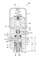
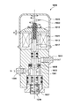
- FIG. 1 and 2 are side sectional views showing a configuration of a solenoid valve 100 according to an embodiment of the present invention.
- FIG. 1 shows a state where the solenoid valve 100 is closed
- FIG. 2 shows a state where the solenoid valve 100 is opened.
- the solenoid valve 100 is, for example, a two-way valve that circulates a liquid or gas that can be used for a supply valve used for a pressurized fluid used in a high-pressure washing apparatus, a high-pressure test apparatus, or the like.
- the present invention can be applied not only to a two-way valve but also to a three-way valve.
- a solenoid valve 100 includes a housing 1 constituting a main body of the valve, and an electromagnetic driving unit 2 that is fixed to the housing 1 with a bolt or the like to open and close the valve.
- the housing 1 is formed by processing a metal such as aluminum, and has a tunnel-like through hole 13 into which a stem 11 that is a shaft for opening and closing a valve is inserted. A fluid such as liquid or gas flows inside the through hole 13, and the flow is opened and closed by the movement of the stem 11.
- An inlet port 15 through which fluid flows into the through hole 13 and an outlet port 17 through which fluid flows out from the through hole 13 are formed on the side of the housing 1.
- Female threads are formed on the inner side surfaces of the inlet port 15 and the outlet port 17, and joints 19 and 21 for fixing the connection pipe between the fluid supply source and the supply destination are screwed into this portion. Is fixed.
- a valve body 11c having conical tapered surfaces 11a and 11b is formed on both sides of a direction along the central axis of the stem 11 (vertical direction in FIG. 1) at an intermediate portion of the stem 11.
- the stem 11 can be slid in the vertical direction in the figure as indicated by an arrow A by the electromagnetic drive unit 2. Then, the stem 11 moves upward, and the upper tapered surface 11a of the valve body 11c is brought into pressure contact with an annular seal member 23 mounted in the through hole 13 as shown in FIG. The flow of fluid flowing from the outlet port 17 to the outlet port 17 is blocked. That is, the solenoid valve 100 is closed.
- a first piston 29 to which a sealing O-ring 27 is attached is formed at the upper end of the stem 11.
- the first piston 29 slides inside the upper portion 13 a of the through hole 13.
- a second piston 33 to which a sealing O-ring 31 is attached is formed at the lower end of the stem 11.
- a guide member 37 to which a sealing O-ring 35 is attached is disposed in the lower portion 13 b of the through hole 13, and the second piston 33 slides inside the guide member 37.
- the guide member 37 is arranged with respect to the seal member 23 via a sleeve 39.
- a female screw 41 is formed at the lower portion of the housing 1, and a fixing screw 43 for fixing the guide member 37 is screwed into this portion.
- the fixing screw 43 is screwed into the female screw 41, thereby pressing and fixing the guide member 37, the sleeve 39, and the seal member 23 to the step portion 1 a formed in the housing 1.
- a cylindrical space 43a is formed inside the fixing screw 43, and a compression coil spring 45 is disposed in the cylindrical space 43a.
- the fixing screw 43 functions as a case member for positioning the compression coil spring 45 that is an elastic body.
- the compression coil spring 45 urges the inner bottom surface 43 b of the fixing screw 43 in the direction of pushing up the lower surface of the second piston 33 of the stem 11. Therefore, in a natural state where the force of the electromagnetic drive unit 2 is not working, the stem 11 is pushed upward by the force of the compression coil spring 45. As a result, the force of the compression coil spring 45 causes the valve body 11c to be pressed against the seal member 23, thereby generating a force for closing the solenoid valve 100.
- the solenoid valve 100 of the present embodiment is a normally closed two-way valve that is closed in a natural state.
- An annular spacer 46 is interposed between the lower surface of the compression coil spring 45 and the inner bottom surface 43 b of the fixing screw 43. The role of this spacer will be described later.
- the electromagnetic drive unit 2 has a fixed core 53 made of a magnetic material such as iron, in which a conducting wire 51 is wound in a coil shape.
- the fixed core 53 is fixed to the housing 1 with a bolt or the like via a spacer 54.
- a through hole 53a that penetrates the fixed core 53 in the vertical direction is formed.
- a rod-shaped movable core 55 made of a non-magnetic material for pushing down the upper surface of the first piston 29 of the stem 11 is inserted into the through hole 53a of the fixed core 53.
- a female screw 55a is formed at the upper end of the rod-shaped movable core 55, and a receiving seat 61 for receiving the bottom surface of the compression coil spring 59 is fixed by screwing a bolt 58 into the female screw 55a.
- a gap d is formed between the lower surface 57 a of the umbrella-shaped movable core 57 and the upper surface 53 b of the fixed core 53, and when the conductive wire 51 is energized, the umbrella-shaped movable core 57 is attracted to the fixed core 53. , And moves downward by the distance of the cap d.
- the force that attracts the umbrella-shaped movable core 57 of the electromagnetic drive unit 2 is set to be larger than the compression force of the lower compression coil spring 45. Therefore, when the conducting wire 51 is energized, the umbrella-shaped movable core 57 overcomes the force of the compression coil spring 45 and moves downward by the distance of the gap d, and the rod-shaped movable core 55 pushes down the stem 11 by the distance of the gap d. Thereby, the valve body 11c is separated from the seal member 23, and the solenoid valve 100 is opened.
- a bottomed cylindrical cover (cover member) 63 is mounted outside the fixed core 53 of the electromagnetic drive unit 2 so as to cover the electromagnetic drive unit 2 and fixed to the fixed core 53 with screws 65 or the like. ing.
- the compression coil spring 59 biases the umbrella-shaped movable core 57 downward with respect to the cover 63 with a force weaker than the force by which the lower compression coil spring 45 pushes up. That is, the compression coil spring 59 applies a weak force in the direction opposite to the biasing direction of the compression coil spring 45 to the umbrella-shaped movable core 57. Thereby, the compression coil spring 59 prevents the umbrella-shaped movable core 57 from vibrating without overcoming the force of the compression coil spring 45 and pushing down the umbrella-shaped movable core 57.
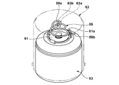
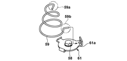
- FIGS. 3A to 3C are views showing a portion where the compression coil spring 59 of the electromagnetic drive unit 2 is mounted.
- FIG. 3A is a view of the compression coil spring 59 attached to the umbrella-shaped movable core 57 via the receiving seat 61 as viewed obliquely from above
- FIG. 3B is a view of the compression coil spring 59 as viewed from the side.
- FIG. 3C is a diagram showing how the compression coil spring 59 is assembled.
- the compression coil spring 59 is formed by being wound in a substantially conical shape so that the diameter of the lower portion is large and the diameter decreases toward the top.
- a first locking portion 59a that is bent inward from the circumference of the coil is formed at one end of the coil that hits the conical top.
- a pair of protrusions 63a and 63b are formed on the ceiling surface of the cover 63 so as to sandwich the first locking portion 59a from both sides.
- the compression coil spring 59 is prevented from rotating with respect to the cover 63 by the first locking portion 59 a of the compression coil spring 59 being sandwiched between the pair of protrusions 63 a and 63 b.
- a second locking portion 59b that is bent outward from the circumference of the coil is formed at the end portion (the other end portion) of the base portion of the compression coil spring 59.
- a part of the plate-like receiving seat 61 is bent and a locking hole 61a is formed in that part.
- the umbrella-shaped movable core 57 is extended with respect to the cover 63 by the first and second locking portions 59a and 59b of the compression coil spring 59, the pair of protrusions 63a and 63b of the cover 63, and the locking hole 61a.
- the rotation with respect to the fixed core 53 is prevented.
- the conventional solenoid valve 1000 shown in FIG. 6 has no structure for preventing the rotation of the umbrella-shaped movable core 1015 relative to the coil 1013 (core).
- the rod-shaped movable core 1021 of the umbrella-shaped movable core 1015 may slide. It may tilt slightly by the gap.
- the dimension of the gap d between the umbrella-shaped movable core 1015 and the core changes, and the operation and suction when the umbrella-shaped movable core is attracted to the core.
- timing may be variations in timing.
- the first and second engaging portions 59a and 59b of the compression coil spring 59, the pair of projecting portions 63a and 63b of the cover 63, and the engaging hole 61a are movable in an umbrella shape. Since the core 57 is prevented from rotating with respect to the fixed core 53, the operation and suction timing when the umbrella-shaped movable core 57 is attracted to the fixed core 53 can be controlled with high accuracy and stability. .
- the root portion of the rod-like movable core 55 fixed to the umbrella-like movable core 57 by press-fitting is made thicker than the tip portion 55b of the rod-like movable core 55 to form an enlarged diameter portion 55c.
- the rod-shaped movable core 55 is integrally formed with a tip portion 55b and an enlarged diameter portion 55c. Since the root portion is formed to be thick in this manner, the inclination of the rod-shaped movable core 55 with respect to the fixed core 53 is reduced if the gap and the fitting length are the same in the fitting with the fixed core 53. Therefore, the operation in which the umbrella-like movable core 57 is attracted to the fixed core 53 is stabilized. Note that the sliding surface of the inner surface of the through hole 53a of the fixed core 53 with the enlarged diameter portion 55c is plated with nickel so that the sliding is smooth.
- the valve opening / closing timing needs to have extremely high accuracy. Therefore, in the conventional solenoid valve, as already described in the background art section, the built-in length of the compression coil spring 1007 that presses the valve body 1003 against the seal member 1005 is adjusted with the adjusting screw 1019. By adjusting this built-in length, theoretically, the force for pressing the valve body against the seal member becomes constant, and the timing of opening and closing the solenoid valve should be controlled with high accuracy.
- this adjustment is very delicate, and it is extremely difficult to make the characteristics of a plurality of solenoid valves uniform.
- the adjustment may be shifted after the adjustment. As a result, in the conventional structure, it is inevitable that some error occurs in the timing of opening and closing the valve. In the present embodiment, a structure that solves this problem is used.
- the dimensional accuracy of each component is managed with high accuracy. Then, the dimensions of each manufactured part are actually measured, and the total dimensional error caused by the accumulation of the tolerances of each part is determined between the lower surface of the compression coil spring 45 and the inner bottom surface (support surface) 43b of the fixing screw 43. Adjustment is performed by sandwiching the spacer 46.
- the dimension L1 from the inner bottom surface 43b of the fixing screw 43 on which the compression coil spring 45 is seated to the surface with which the valve body 11c of the seal member 23 contacts is the upper end of the fixing screw 43 from the inner bottom surface 43b of the fixing screw 43.
- the total dimensions are obtained by measuring the dimensions of each part.
- the dimension L2 from the lower surface of the second piston 33 that the compression coil spring 45 contacts to the point where the valve body 11c contacts the seal member 23 is also measured. For these dimensions, the thickness of the spacer 46 is adjusted so that the built-in length of the compression coil spring 45 falls within an error of, for example, about 0.05 mm with respect to the design value.
- FIG. 4 is a diagram showing an actual shape of the spacer 46.
- the spacer 46 has a disk-shaped outer peripheral portion 46a and a central portion 46b protruding upward in a columnar shape.
- a chamfer is formed on the outer peripheral portion of the central portion 46b, so that the inner peripheral surface of the compression coil spring 45 is easily fitted.
- the compression coil spring 45 is cylindrical so that the inner peripheral surface thereof is guided by the central portion 46 b of the spacer 46 and a gap S 1 is formed between the outer periphery of the compression coil spring 45 and the cylindrical space 43 a of the fixing screw 43. Is positioned at the center in the space 43a (in the space).
- the gap S1 is set larger than the space S2 between the outer peripheral portion 46a of the spacer 46 and the cylindrical space 43a.
- a through hole 46c is formed in the central portion of the spacer 46, and a through hole 43c is formed in the bottom surface of the fixing screw 43 so as to relieve the pressure in the cylindrical space 43a. Yes.
- the size of the gap d between the umbrella-shaped movable core 1015 and the coil 1013 is adjusted by rotating the adjustment screw 1021, as already described in the background art section.
- the opening / closing timing of the solenoid valve 1000 is adjusted. If the gap d is adjusted, the timing of opening / closing the solenoid valve should theoretically be controlled with high accuracy. However, also in this adjustment, it is extremely difficult to make the characteristics of the plurality of solenoid valves uniform. In addition, the adjustment may be shifted after the adjustment.
- the gap d between the umbrella-shaped movable core 57 and the fixed core 53 is not adjusted with the adjusting screw, but first, the dimensional accuracy of each component is managed with high accuracy. To do. Then, the dimensions of each manufactured part are actually measured, and the total dimensional error caused by the accumulation of tolerances of each part is adjusted by sandwiching the spacer 54 between the lower surface of the fixed core 53 and the upper surface of the housing 1. To do.
- the dimension L3 from the point at which the valve body 11c contacts the seal member 23 to the lower surface 57a of the umbrella-shaped movable core 57 is determined from the point at which the valve body 11c contacts the seal member 23.
- the dimension is obtained by adding the dimension up to the upper surface and the dimension from the tip of the rod-shaped movable core 55 to the mounting step of the umbrella-shaped movable core 57.
- the total dimensions of this part are obtained by measuring the dimensions of each part.
- the dimension from the lower surface of the seal member 23 to the upper surface of the fixed core 53 is also measured. Then, with respect to these dimensions, the thickness of the spacer 54 is adjusted such that the dimension of the gap d falls within an error of, for example, about 0.05 mm.
- the adjustment is performed by the dimensional accuracy of the parts and the spacer, thereby reducing the adjustment effort and preventing the adjustment from going wrong after the adjustment.
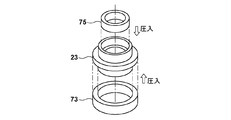
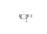
- FIGS. 5A to 5D are views showing the structure of the seal member 23 in FIG.
- the seal member 23 is generally formed of a resin material such as nylon, for example, in order to improve the sealing performance due to contact with the valve body 11c. 5A, the tapered surface 11a of the valve body 11c is pressed against the lower portion 23a of the seal member 23. Therefore, a force (internal pressure) for expanding the opening 23b is applied to the lower portion 23a of the seal member 23. . Further, since the sealing O-ring 71 is mounted on the outer peripheral portion of the upper portion 23c of the seal member 23, a force (external pressure) for crushing from the outside to the inside is applied.
- the first metal ring 73 is mounted on the outer periphery of the lower portion of the seal member 23 so as to reinforce the seal member 23 and prevent deformation.
- a second metal ring 75 is disposed on the inner periphery of the member 23.
- the seal member 23 that is a resin portion and the first and second metal rings 73 and 75 are integrally formed by insert molding. In this way, it is possible to manufacture a highly accurate seal member without causing deformation or inclination due to press-fitting. Further, since the seal member 23 can be manufactured with high accuracy, the position of the contact point between the valve body 11c and the seal member 23 is determined with high accuracy, and as a result, the dimension of the gap d shown in FIG. 1 is set with high accuracy. Will be. As a result, the suction operation of the umbrella-shaped movable core 57 by the fixed core 53 is stabilized, and problems such as a shift in suction timing are solved.
- the first and second metal rings can be completely covered with a resin material.
- the umbrella-shaped movable core is attached to the electromagnetic coil.
- the stability of the absorbed operation is improved.
- the spring force can be adjusted accurately without requiring delicate adjustment. Further, it is possible to prevent the adjustment from being shifted after the adjustment.
- the operation of the coil adsorbing the umbrella-shaped movable core is stabilized without requiring any delicate adjustment. Further, it is possible to prevent the adjustment from being shifted after the adjustment.
- the inclination of the rod-shaped movable core is reduced, the dimension of the gap between the umbrella-shaped movable core and the coil is stabilized, and the adsorption operation is stabilized.
- a fixed core (53) of an electromagnetic coil for driving an umbrella-shaped movable core (57) connected to a rod-shaped movable core (55) that pushes the valve body (11c) is provided on the housing (1).
- the solenoid valve (100) including the coil spring (59) between the cover member (63) covering the fixed core (53) and the umbrella-shaped movable core (57) the coil spring (59) is connected to the cover member (63).
- a solenoid valve having a mounting portion for connecting the movement of the umbrella-shaped movable core (57).
- the rod-shaped movable core (55) includes an enlarged diameter portion (55c) having a diameter larger than that of the distal end portion (55b) for pushing the valve body (11c) inside the fixed core (53).
- Characteristic solenoid valve for attaching a fixed core (53) of an electromagnetic coil for driving an umbrella-shaped movable core (57) connected to a rod-shaped movable core (55) for pushing the valve element (11c) to the housing (1) 100
- the rod-shaped movable core (55) includes an enlarged diameter portion (55c) having a diameter larger than that of the distal end portion (55b) for pushing the valve body (11c) inside the fixed core (53).
- a fixed core (53) of an electromagnetic coil for driving an umbrella-shaped movable core (57) connected to a rod-shaped movable core (55) that pushes the valve body (11c) is provided on the housing (1).
- the case member (43) that houses the elastic body (45) for moving the valve body (11c) up and down is attached to the housing (1)
- the case member (43) is directly fixed to the housing (1)
- Solenoid valve for attaching a fixed core (53) of an electromagnetic coil for driving an umbrella-shaped movable core (57) connected to a rod-shaped movable core (55) for pushing the valve element (11c) to the housing (1) 100), the rod-like movable core (55) and the umbrella-like movable core (57) are press-fitted and fixed, and a spacer (54) is provided between the fixed core (53) and the housing (1). Solenoid valve. [5] A fixed core (53) of an electromagnetic coil that drives an umbrella-shaped movable core (57) connected to a rod-shaped movable core (55) that pushes the valve body (11c) is provided on the housing (1).
- the seal member (23) contacts the valve body (11c).
- the resin ring (23c), the outer metal ring (73) outside the portion in contact with the valve body (11c), and the O-ring (71) arranged above the outer metal ring (73) are arranged.
- the inner metal ring (75) is combined and the outer metal ring (73) and the inner metal ring (75) are integrally formed of a resin material forming the resin ring (23c).
- Each of the above features can stabilize the gap between the umbrella-shaped movable core and the coil even if each is independent, but by using these in combination, it is possible to further stabilize the adsorption operation.
- a higher effect can be obtained by combining the above [3] and [4] based on the measurement result of each part.
Landscapes
- Engineering & Computer Science (AREA)
- General Engineering & Computer Science (AREA)
- Mechanical Engineering (AREA)
- Magnetically Actuated Valves (AREA)
Abstract
本発明は、ソレノイドバルブの動作の精度を向上させる。ソレノイドバルブは、流体が流入する入口ポートと、流体が流出する出口ポートと、入口ポートと出口ポートの間の流体の流路に配置され、開口を有するシール部材と、シール部材の開口を開閉して、流路を開閉する弁体と、シール部材の開口を閉じるように、弁体をシール部材に付勢する第1のバネと、弁体を移動させる傘状可動コアと、傘状可動コアを吸着する電磁コイルとを有し、電磁コイルに通電されることにより、傘状可動コアを吸着して前記弁体をシール部材の開口から離間させて開口を開くように動作する電磁駆動部と、第1のバネのバネ力よりも弱く第1のバネの付勢方向とは逆方向のバネ力を傘状可動コアに作用させる第2のバネと、を備え、第2のバネに、傘状可動コアの電磁コイルに対する回転を防止する回り止め部を設けた。
Description
本発明は、加圧流体の流路を開閉するソレノイドバルブに関するものである。
従来より、加圧流体の流路を開閉するバルブとして、電磁ソレノイドを用いた2方弁、3方弁などが広く用いられている。このようなソレノイドバルブの1つとして、例えば特許文献1には、高圧洗浄装置や高圧流体供給装置等に利用される加圧流体用途に用いられる流体供給バルブなどに適用可能な2方弁が開示されている。
この特許文献1に開示されているソレノイドバルブをはじめとする従来の一般的な2方弁の構造について、図6、図7を参照して説明する。
図6及び図7は、従来のソレノイドバルブ1000の構成を示す側断面図である。図6は、ソレノイドバルブ1000が閉じた状態を示し、図7は、ソレノイドバルブ1000が開いた状態を示している。
図6において、ソレノイドバルブ1000は、中央を貫通するシャフト状のステム1001を有する。ステム1001に形成された弁体1003がシール部材1005に対して圧縮コイルバネ1007の力で押し付けられることにより、入口ポート1009から出口ポート1011に至る経路が閉じられ、ソレノイドバルブ1000は閉止状態に保たれる。一方、コイル1013に通電することにより、図7に示すように、コイル1013により磁性体からなる傘状可動コア1015がギャップdの分だけ引き寄せられる。それに伴って棒状可動コア1017が圧縮コイルバネ1007の力に抗してステム1001を押し下げ、弁体1003がシール部材1005から離れる。これにより、入口ポート1009から出口ポート1011に至る経路が開き、ソレノイドバルブ1000は開状態となる。傘状可動コア1015とカバー1025の間には弱い圧縮コイルバネ1023が配置され、傘状可動コア1015の振動を抑制する働きをする。
なお、圧縮コイルバネ1007の組み込み長が調整ネジ1019を回転させることにより調整され、弁体1003をシール部材1005に押し付ける力が調整される。また、調整ネジ1021を回転させることにより、傘状可動コア1015とコイル1013の間のギャップdの大きさが調整され、ソレノイドバルブ1000の開閉動作が安定化される。
しかしながら、上述した特許文献1のような構成では、ギャップdの大きさにばらつきがあると吸引速度がばらつき、ソレノイドバルブの動作の精度を低下させることがあった。
本発明は上述した課題に鑑みてなされたものであり、ソレノイドバルブの動作の精度を向上させるものである。
本発明に係わるソレノイドバルブは、流体が流入する入口ポートと、流体が流出する出口ポートと、前記入口ポートと前記出口ポートの間の流体の流路に配置され、開口を有するシール部材と、前記シール部材の前記開口を開閉して、前記流路を開閉する弁体と、前記シール部材の前記開口を閉じるように、前記弁体を前記シール部材に付勢する第1のバネと、前記弁体を移動させる傘状可動コアと、該傘状可動コアを吸着する電磁コイルとを有し、該電磁コイルに通電されることにより、前記傘状可動コアを吸着して前記弁体を前記シール部材の前記開口から離間させて前記開口を開くように動作する電磁駆動手段と、前記第1のバネのバネ力よりも弱く前記第1のバネの付勢方向とは逆方向のバネ力を前記傘状可動コアに作用させる第2のバネと、を備え、前記第2のバネに、前記傘状可動コアの前記電磁コイルに対する回転を防止する回り止め手段を設けたことを特徴とする。
本発明によれば、ソレノイドバルブの動作の精度を向上させることが可能となる。
本発明のその他の特徴及び利点は、添付図面を参照とした以下の説明により明らかになるであろう。なお、添付図面においては、同じ若しくは同様の構成には、同じ参照番号を付す。
添付図面は明細書に含まれ、その一部を構成し、本発明の実施の形態を示し、その記述と共に本発明の原理を説明するために用いられる。
本発明の一実施形態のソレノイドバルブの構成を示す側断面図。
本発明の一実施形態のソレノイドバルブの構成を示す側断面図。
電磁駆動部の圧縮コイルバネの部分を抜き出して示した図。
電磁駆動部の圧縮コイルバネの部分を抜き出して示した図。
電磁駆動部の圧縮コイルバネの部分を抜き出して示した図。
圧縮コイルバネのスペーサーを拡大して示した図。
シール部材の構成を示す図。
シール部材の構成を示す図。
シール部材の構成を示す図。
シール部材の構成を示す図。
従来のソレノイドバルブの構成を示す側断面図。
従来のソレノイドバルブの構成を示す側断面図。
以下、本発明のソレノイドバルブの一実施形態について、添付図面を参照して詳細に説明する。
図1及び図2は、本発明の一実施形態のソレノイドバルブ100の構成を示す側断面図である。図1は、ソレノイドバルブ100が閉じた状態を示し、図2は、ソレノイドバルブ100が開いた状態を示している。ソレノイドバルブ100は、例えば、高圧洗浄装置や高圧試験装置などに利用する加圧流体に用いられる供給バルブなどに使用可能な液体や気体などを流通させる2方弁である。但し、本発明は、2方弁に限らず3方弁にも適用可能である。
図1において、ソレノイドバルブ100は、大きく分けてバルブの本体を構成するハウジング1と、ハウジング1に対してボルトなどにより固定されバルブの開閉駆動を行う電磁駆動部2とを備える。
ハウジング1は、アルミニウムなどの金属を加工して形成され、内部に弁の開閉を行うシャフトであるステム11が挿通されるトンネル状の貫通穴13が形成されている。この貫通穴13の内部を液体あるいは気体などの流体が流れ、ステム11の動きにより、この流れの開閉が行われる。
ハウジング1の側部には、貫通穴13内に流体が流入する入口ポート15と、貫通穴13内から流体を流出させる出口ポート17が形成されている。入口ポート15及び出口ポート17の内側面には雌ネジが形成されており、この部分に流体の供給源および供給先との間で接続パイプを固定するための継手19,21が捩じ込まれて固定されている。
ステム11の中間部には、ステム11の中心軸に沿う方向(図1では上下方向)の両側に円錐状のテーパ面11a,11bを有する弁体11cが形成されている。ステム11は、詳細は後述するが、電磁駆動部2により、矢印Aで示すように図中上下方向にスライド可能である。そして、このステム11が上側に移動して、図1に示すように弁体11cの上側のテーパ面11aが貫通穴13に装着された環状のシール部材23に圧接されることにより、入口ポート15から出口ポート17へと流れる流体の流れが遮断される。つまり、ソレノイドバルブ100が閉じた状態となる。一方、ステム11が下側に移動すると、弁体11cの上側のテーパ面11aが、シール部材23から離れ、シール部材23と弁体11cとの間に隙間25が形成される。これにより、流路が形成され、入口ポート15に供給された流体が、隙間25を通って出口ポート17へと流れ、ソレノイドバルブ100が開いた状態となる。
以上が本実施形態のソレノイドバルブの概略的な構造である。
次に、ステム11を電磁駆動部2により矢印Aで示す上下方向にスライドさせる機構について説明する。
図1において、ステム11の上側の端部には、シール用のOリング27が装着された第1のピストン29が形成されている。第1のピストン29は、貫通穴13の上部13aの内側をスライドする。また、ステム11の下側の端部には、シール用のOリング31が装着された第2のピストン33が形成されている。貫通穴13の下部13bには、シール用のOリング35が装着されたガイド部材37が配置されており、第2のピストン33は、このガイド部材37の内側をスライドする。
ガイド部材37は、シール部材23に対してスリーブ39を介して配置されている。ハウジング1の下部には、雌ネジ41が形成されており、この部分にガイド部材37を固定するための固定ネジ43が捩じ込まれる。固定ネジ43は、雌ネジ41に捩じ込まれることにより、ガイド部材37、スリーブ39、シール部材23を、ハウジング1に形成された段部1aに押し付けて固定する。
固定ネジ43の内側には円筒状の空間43aが形成されており、この円筒状の空間43aには、圧縮コイルバネ45が配置されている。固定ネジ43は、弾性体である圧縮コイルバネ45を位置決めするケース部材として機能する。圧縮コイルバネ45は、固定ネジ43の内側底面43bに対してステム11の第2のピストン33の下面を押し上げる方向に付勢している。そのため、電磁駆動部2の力が働いていない自然状態においては、ステム11は、圧縮コイルバネ45の力により図中上側に押し上げられている。結果として、この圧縮コイルバネ45の力により、弁体11cがシール部材23に押し付けられ、ソレノイドバルブ100を閉止させる力が発生する。従って、本実施形態のソレノイドバルブ100は、自然状態で閉じているノーマルクローズの2方弁である。なお、圧縮コイルバネ45の下面と固定ネジ43の内側底面43bの間には円環状のスペーサ46が挟まれて配置されている。このスペーサの役割については後述する。
一方、電磁駆動部2は、導線51がコイル状に巻き回された、鉄などの磁性体からなる固定コア53を有する。固定コア53は、詳細は後述するが、スペーサ54を介してハウジング1に対してボルトなどにより固定されている。固定コア53の中央には、固定コア53を上下方向に貫通する貫通穴53aが形成されている。固定コア53の貫通穴53aには、ステム11の第1のピストン29の上面を押し下げるための非磁性体からなる棒状可動コア55が挿入されている。そして、棒状可動コア55の上端部には、導線51に通電されたときに固定コア53に生じる磁力により引き付けられる、磁性体からなる傘状可動コア57が圧入により固定されている。棒状可動コア55の上端部には、雌ネジ55aが形成されており、この雌ネジ55aにボルト58を捩じ込むことにより、圧縮コイルバネ59の底面を受けるための受け座61を固定する。
なお、傘状可動コア57の下面57aと固定コア53の上面53bの間には、ギャップdが形成されており、導線51に通電されると、傘状可動コア57は固定コア53に吸着され、このキャップdの距離だけ下方に移動する。電磁駆動部2の傘状可動コア57を引き付ける力は、下側の圧縮コイルバネ45の圧縮力よりも大きく設定されている。そのため、導線51に通電されると、傘状可動コア57が圧縮コイルバネ45の力に打ち勝ってギャップdの距離だけ下方に移動し、棒状可動コア55がステム11をギャップdの距離だけ押し下げる。これにより、弁体11cがシール部材23から離間され、ソレノイドバルブ100は開いた状態となる。
電磁駆動部2の固定コア53の外側には、この電磁駆動部2を覆うように、有底円筒状のカバー(カバー部材)63が装着され、ビス65などにより固定コア53に対して固定されている。圧縮コイルバネ59は、カバー63に対して傘状可動コア57を、下側の圧縮コイルバネ45が押し上げる力よりも弱い力で下側に付勢している。つまり、圧縮コイルバネ59は圧縮コイルバネ45の付勢方向とは逆方向の弱い力を傘状可動コア57に作用させている。これにより、圧縮コイルバネ59は、圧縮コイルバネ45の力に打ち勝って傘状可動コア57を押し下げることなく、傘状可動コア57が振動することを防止している。
ここで、上記の圧縮コイルバネ59について、もう少し詳しく説明する。図3A-3Cは、電磁駆動部2の圧縮コイルバネ59が装着されている部分を抜き出して示した図である。図3Aは、傘状可動コア57に受け座61を介して装着された圧縮コイルバネ59を斜め上から見た図であり、図3Bは、圧縮コイルバネ59を側方から見た図である。また、図3Cは、圧縮コイルバネ59を組み付ける様子を示す図である。
図3A-3Cにおいて、圧縮コイルバネ59は、低部の直径が大きく、上方に行くにつれて直径が小さくなるように、概略円錐状に巻かれて形成されている。この円錐状の頂部に当たるコイルの一端部には、コイルの円周から内側に向けて曲げられた第1の係止部59aが形成されている。一方、カバー63の天井面には、この第1の係止部59aを両側から挟むように、一対の突起部63a,63bが形成されている。図3Bに示すように、圧縮コイルバネ59の第1の係止部59aがこの一対の突起部63a,63bに挟まれることにより、圧縮コイルバネ59は、カバー63に対する回転が阻止される。
また、圧縮コイルバネ59の基部の端部(他端部)には、コイルの円周から外側に向けて曲げられた第2の係止部59bが形成されている。一方、板状の受け座61は、その一部が立ち曲げされており、その部分に係止孔61aが形成されている。図3Cに示すように、圧縮コイルバネ59の第2の係止部59bがこの係止孔61aに挿入されることにより、傘状可動コア57は、受け座61を介して圧縮コイルバネ59に対する回転が防止される。
結果として、圧縮コイルバネ59の第1及び第2の係止部59a,59b、カバー63の一対の突起部63a,63b、係止孔61aにより、傘状可動コア57がカバー63に対して、ひいては固定コア53に対して回転することが防止される。
すでに背景技術の欄で説明したように、図6に示す従来のソレノイドバルブ1000では、傘状可動コア1015のコイル1013(コア)に対する回転を阻止する構造が無かった。もともと、傘状可動コア1015の棒状可動コア1021の外径とコアの貫通穴の内径には棒状可動コア1021がスライドできるようにわずかな隙間があり、傘状可動コア1015がコアに対してその隙間分だけ僅かに傾くことがある。その状態で更に傘状可動コア1015がコアに対して回転すると、傘状可動コア1015とコアの間のギャップdの寸法が変動し、傘状可動コアがコアに吸引されるときの動作や吸着タイミングにばらつきが生じることがある。
この点、本実施形態では、上記のように、圧縮コイルバネ59の第1及び第2の係止部59a,59b、カバー63の一対の突起部63a,63b、係止孔61aにより、傘状可動コア57が固定コア53に対して回転することが防止されるため、傘状可動コア57が固定コア53に吸引されるときの動作や吸着タイミングを精度良く安定して制御することが可能となる。
また、棒状可動コア55の傘状可動コア57に圧入により固定されている根元部分は、棒状可動コア55の先端部分55bよりも太くされて拡径部55cを形成している。棒状可動コア55は、先端部分55b、拡径部55cが一体的に形成されている。このように根元部分が太く形成されていることにより、固定コア53との嵌合において同じ隙間、同じ嵌合長であれば、棒状可動コア55の固定コア53に対する傾きが小さくなる。そのため、傘状可動コア57が固定コア53に吸着される動作が安定化される。なお、固定コア53の貫通穴53aの内面の拡径部55cとの摺動面には、ニッケルメッキが施され、摺動が滑らかになるように配慮されている。
次に、上記で述べたように、ソレノイドバルブが加圧流体の供給バルブとして用いられる場合などは、バルブの開閉のタイミングの精度は極めて高いことが必要である。そのため、従来のソレノイドバルブでは、すでに背景技術の欄で説明したように、弁体1003をシール部材1005に押し付ける圧縮コイルバネ1007の組み込み長を調整ネジ1019で調整していた。この組み込み長を調整すれば、理論上は弁体をシール部材に押し付ける力が一定になり、ソレノイドバルブの開閉のタイミングを精度良く制御できるはずである。しかしながら、実際にはこの調整は非常に繊細なものであり、複数のソレノイドバルブの特性を同じような特性に揃えることは極めて困難である。また、調整後に調整がずれてしまうこともある。結果として、従来の構造では、バルブの開閉のタイミングにある程度の誤差が生じることは避けられなかった。本実施形態では、この問題を解決する構造を用いている。
図2に示すように、本実施形態では、調整ネジで圧縮コイルバネ45の組み込み長を調整するのではなく、まずは各部品の寸法精度を高精度に管理して製造する。そして、製造された各部品の寸法を実際に測定し、各部品の公差の積み上げにより生じたトータルの寸法誤差を、圧縮コイルバネ45の下面と固定ネジ43の内側底面(支持面)43bの間にスペーサ46を挟むことにより調整する。
より具体的には、圧縮コイルバネ45が着座する固定ネジ43の内側底面43bからシール部材23の弁体11cが接触する面までの寸法L1は、固定ネジ43の内側底面43bから固定ネジ43の上端までの寸法と、ガイド部材37の長手方向の寸法と、スリーブ39の長手方向の寸法を加えた寸法となる。各部品の寸法を測定することによりトータルの寸法を取得する。圧縮コイルバネ45が接触する第2のピストン33の下面から弁体11cがシール部材23に接触する点までの寸法L2も測定する。そして、これらの寸法に対して、圧縮コイルバネ45の組み込み長が例えば設計値に対して0.05mm程度の誤差に収まるようにスペーサ46の厚みを調整する。
本実施形態の場合、上記の各部品の公差を積み重ねると例えば最大0.3mm程度の寸法誤差が生ずる。そのため、スペーサとして、例えば0.05mm~0.3mmまで、0.05mm単位で厚みの異なる6種類のスペーサを用意しておく。そして、上記のような各部品の寸法の実測値に基づき、6種類のスペーサから最適なものを選択して圧縮コイルバネ45の下面と固定ネジ43の内側底面43bの間に挿入する。このようにすれば、圧縮コイルバネ45の組み込み長を精度よく設定でき、後にこの調整が狂うこともない。
図4は、スペーサ46の実際の形状を示す図である。
図4に示すように、スペーサ46は、円板状の外周部46aと、上方に円柱状に突出した中央部46bとを有する。中央部46bの外周部には面取りが形成されており、圧縮コイルバネ45の内周面が嵌りやすいように考慮されている。圧縮コイルバネ45は、内周面をスペーサ46の中央部46bによりガイドされて、圧縮コイルバネ45の外周部と固定ネジ43の円筒状の空間43aとの間に隙間S1が形成されるように、円筒状の空間43a内(空間内)の中心に位置決めされる。この隙間S1は、スペーサ46の外周部46aと円筒状の空間43aとの間の空間S2より大きく設定する。このようにすると、圧縮コイルバネ45が伸び縮みする場合に、圧縮コイルバネ45の外周面と円筒状の空間43aの内周面が擦れて、力の損失やゴミが発生するようなことが防止される。高精度なソレノイドバルブにとって、ゴミは大敵であり、本実施形態のように構成することにより、効果的にゴミの発生を抑制することができる。圧縮コイルバネ45の力量の損失が生じることもない。なお、スペーサ46の中央部46bの外径を圧縮コイルバネ45の内径よりもわずかに大きくして、中央部46bを圧縮コイルバネ45の内周に軽圧入状態とすると、部品の組み込み時にスペーサ46と圧縮コイルバネ45とが一体となった状態で組み込めるため、組み立て性が向上する。
なお、スペーサ46の中央部には貫通穴46cが形成されているとともに、固定ネジ43の底面には貫通穴43cが形成されており、円筒状の空間43a内の圧力を逃がすように構成されている。
次に、バルブの開閉のタイミングの精度を高めるための本実施形態のさらなる構成について図1に戻って説明する。
図6に示す従来のソレノイドバルブでは、すでに背景技術の欄で説明したように、調整ネジ1021を回転させることにより、傘状可動コア1015とコイル1013の間のギャップdの大きさが調整され、ソレノイドバルブ1000の開閉タイミングが調整される。このギャップdの調整を行えば、理論上はソレノイドバルブの開閉のタイミングを精度良く制御できるはずである。しかしながら、やはりこの調整においても、複数のソレノイドバルブの特性を同じような特性に揃えることは極めて困難である。また、調整後に調整がずれてしまうこともある。
図1に示すように、本実施形態では、調整ネジで傘状可動コア57と固定コア53の間のギャップdを調整するのではなく、まずは各部品の寸法精度を高精度に管理して製造する。そして、製造された各部品の寸法を実際に測定し、各部品の公差の積み上げにより生じたトータルの寸法誤差を、固定コア53の下面とハウジング1の上面の間にスペーサ54を挟むことにより調整する。
より具体的には、弁体11cがシール部材23に接触する点から傘状可動コア57の下面57aまでの寸法L3は、弁体11cがシール部材23に接触する点から第1のピストン29の上面までの寸法と、棒状可動コア55の先端から傘状可動コア57の取り付け段部までの寸法を加えた寸法となる。各部品の寸法を測定することによりこの部分のトータルの寸法を取得する。シール部材23の下面から固定コア53の上面までの寸法も測定する。そして、これらの寸法に対して、ギャップdの寸法が例えば0.05mm程度の誤差に収まるようにスペーサ54の厚みを調整する。
本実施形態の場合、上記の各部品の公差を積み重ねると例えば最大0.3mm程度の寸法誤差が生ずる。そのため、スペーサとして、例えば0.05mm~0.3mmまで、0.05mm単位で厚みの異なる6種類のスペーサを用意しておく。そして、上記のような各部品の寸法の実測値に基づき、6種類のスペーサから最適なものを選択して固定コア53の下面とハウジング1の上面の間に挿入する。このようにすれば、傘状可動コア57の下面57aと固定コア53の上面とのギャップdの大きさを精度よく設定でき、後にこの調整が狂うこともない。
以上のようにして、本実施形態では、部品の寸法精度とスペーサにより調整を行い、調整の手間を減らすとともに、調整後に調整が狂うことを防止している。
次に、図5A-5Dは、図1におけるシール部材23の構造を示す図である。
シール部材23は、弁体11cとの接触による密封性を向上させるために、一般的に例えばナイロンなどの樹脂材料により形成されている。そして、図5Aに示すように、シール部材23の下部23aには、弁体11cのテーパ面11aが押しつけられるため、シール部材23の下部23aには、開口23bを押し広げる力(内圧)が加わる。また、シール部材23の上部23cは、外周部にシール用のOリング71が装着されるため、外側から内側に押しつぶす力(外圧)が加わる。そのため、シール部材23の密閉性を確保するために、シール部材23を補強して変形を防ぐように、シール部材23の下部には、その外周部に第1の金属リング73が装着され、シール部材23の上部には、その内周部に第2の金属リング75が配置されるのが一般的である。そして、図5Bに示すように、金属リング73,75のシール部材23への取り付けは、従来圧入により行われていた。そのため、圧入時にシール部材23の変形や金属リングの傾きなどが生じやすく、部品の精度低下を招く場合があった。
これに対し、本実施形態では、図5Cに示すように、インサート成形により樹脂部分であるシール部材23と第1及び第2の金属リング73,75を一体成形して製造する。このようにすれば、圧入による変形や傾きなどが生じることなく精度の良いシール部材を製造することが可能となる。また、このシール部材23が精度よく製造できることにより、弁体11cのシール部材23との接触点の位置が精度よく決まることになり、結果として、図1に示すギャップdの寸法が精度良く設定されることになる。結果として、固定コア53による傘状可動コア57の吸着動作が安定化し、吸着タイミングのずれ等の問題が解消される。
また、シール部材23を一体成形する場合には、図5Dに示すように、第1及び第2の金属リングを樹脂材料で完全に覆ってしまうことも可能である。
以上説明したように、上記の実施形態によれば、傘状可動コアの振動を抑える圧縮コイルバネに傘状可動コアの回転を防止する回り止めを設けたことにより、傘状可動コアが電磁コイルに吸着される動作の安定性が向上される。
また、弁体をシール部材に押し付けるバネの組み込み長をスペーサを用いて調整することにより、繊細な調整を必要とせず、バネ力を正確に調整することが出来る。また調整した後に調整がずれてしまうことも防止される。
また、傘状可動コアとコイルの間のギャップをスペーサを用いて調整することにより、やはり繊細な調整を必要とせず、コイルが傘状可動コアを吸着する動作が安定化される。また調整した後に調整がずれてしまうことも防止される。
また、シール部材に金属リングを一体成形することにより、圧入による部品の変形や傾きが防止され、シール部材の精度が向上される。
さらに、棒状可動コアの根元部分に拡径部を設けることにより、棒状可動コアの傾きが小さくなり、傘状可動コアとコイル間のギャップの寸法が安定化され、吸着動作が安定化される。
以上の実施形態の各特徴をまとめると、以下のように表現することができる。
〔1〕弁体(11c)を押動する棒状可動コア(55)と連結される傘状可動コア(57)を駆動する電磁コイルの固定コア(53)をハウジング(1)の上に設け、固定コア(53)を覆うカバー部材(63)と傘状可動コア(57)との間にコイルバネ(59)を備えたソレノイドバルブ(100)において、コイルバネ(59)は、カバー部材(63)と傘状可動コア(57)の動きを連結する取付部を有することを特徴とするソレノイドバルブ。
〔2〕弁体(11c)を押動する棒状可動コア(55)と連結される傘状可動コア(57)を駆動する電磁コイルの固定コア(53)をハウジング(1)に取り付けるソレノイドバルブ(100)において、棒状可動コア(55)は、固定コア(53)の内側に、弁体(11c)を押動する先端部(55b)よりも径の太い拡径部(55c)を備えることを特徴とするソレノイドバルブ。
〔3〕弁体(11c)を押動する棒状可動コア(55)と連結される傘状可動コア(57)を駆動する電磁コイルの固定コア(53)をハウジング(1)の上に設け、弁体(11c)を上下させる弾性体(45)を収納するケース部材(43)をハウジング(1)に取り付けるソレノイドバルブ(100)において、ケース部材(43)をハウジング(1)に直接固定し、弾性体(45)の下方にスペーサ(43b)を設けたことを特徴とするソレノイドバルブ。
〔4〕弁体(11c)を押動する棒状可動コア(55)と連結される傘状可動コア(57)を駆動する電磁コイルの固定コア(53)をハウジング(1)に取り付けるソレノイドバルブ(100)において、棒状可動コア(55)と傘状可動コア(57)とを圧入して固定し、固定コア(53)とハウジング(1)との間にスペーサ(54)を設けたことを特徴とするソレノイドバルブ。
〔5〕弁体(11c)を押動する棒状可動コア(55)と連結される傘状可動コア(57)を駆動する電磁コイルの固定コア(53)をハウジング(1)の上に設け、弾性体(45)によって上下動作する弁体(11c)の上方に設けられたシール部材(23)を備えたソレノイドバルブ(100)において、シール部材(23)は、弁体(11c)と接触する樹脂リング(23c)と、弁体(11c)と接触する部分の外側の外側金属リング(73)と、外側金属リング(73)の上方に配置されるオーリング(71)の内側に配置される内側金属リング(75)と、を組み合わせて構成され、外側金属リング(73)及び内側金属リング(75)は、樹脂リング(23c)を形成する樹脂材料により一体的に成形されていることを特徴とするソレノイドバルブ。
〔5〕弁体(11c)を押動する棒状可動コア(55)と連結される傘状可動コア(57)を駆動する電磁コイルの固定コア(53)をハウジング(1)の上に設け、弾性体(45)によって上下動作する弁体(11c)の上方に設けられたシール部材(23)を備えたソレノイドバルブ(100)において、シール部材(23)は、弁体(11c)と接触する樹脂リング(23c)と、弁体(11c)と接触する部分の外側の外側金属リング(73)と、外側金属リング(73)の上方に配置されるオーリング(71)の内側に配置される内側金属リング(75)と、を組み合わせて構成され、外側金属リング(73)及び内側金属リング(75)は、樹脂リング(23c)を形成する樹脂材料により一体的に成形されていることを特徴とするソレノイドバルブ。
上記の各特徴は、それぞれ単独であっても傘状可動コアとコイル間のギャップを安定化させることができるが、これらを組み合わせて用いることにより、さらなる吸着動作の安定化を図ることができる。特に、各部品の測定結果に基づく、上記の〔3〕と〔4〕を組み合わせるとより高い効果が得られる。
以上の各効果により、ソレノイドバルブの開閉のタイミングを高精度に制御することが可能となる。
本発明は上記実施の形態に制限されるものではなく、本発明の精神及び範囲から離脱することなく、様々な変更及び変形が可能である。従って、本発明の範囲を公にするために、以下の請求項を添付する。
本願は、2018年2月9日提出の日本国特許出願特願2018-22362を基礎として優先権を主張するものであり、その記載内容の全てを、ここに援用する。
1:ハウジング、2:電磁駆動部、11:ステム、23:シール部材、45:圧縮コイルバネ、46:スペーサ、53:固定コア、54:スペーサ、55:棒状可動コア、57:傘状可動コア、59:圧縮コイルスプリング
Claims (9)
- 流体が流入する入口ポートと、
流体が流出する出口ポートと、
前記入口ポートと前記出口ポートの間の流体の流路に配置され、開口を有するシール部材と、
前記シール部材の前記開口を開閉して、前記流路を開閉する弁体と、
前記シール部材の前記開口を閉じるように、前記弁体を前記シール部材に付勢する第1のバネと、
前記弁体を移動させる傘状可動コアと、該傘状可動コアを吸着する電磁コイルとを有し、該電磁コイルに通電されることにより、前記傘状可動コアを吸着して前記弁体を前記シール部材の前記開口から離間させて前記開口を開くように動作する電磁駆動手段と、
前記第1のバネのバネ力よりも弱く前記第1のバネの付勢方向とは逆方向のバネ力を前記傘状可動コアに作用させる第2のバネと、を備え、
前記第2のバネに、前記傘状可動コアの前記電磁コイルに対する回転を防止する回り止め手段を設けたことを特徴とするソレノイドバルブ。 - 前記第2のバネはコイルバネであり、前記回り止め手段は、前記コイルバネの一端部をコイルの円周から内側に曲げた第1の曲げ部と、前記コイルバネの他端部をコイルの円周から外側に曲げた第2の曲げ部とを有することを特徴とする請求項1に記載のソレノイドバルブ。
- 前記電磁コイルを覆うカバー部材をさらに備え、該カバー部材は、前記第1の曲げ部を係止する第1の係止部を有し、前記傘状可動コアは前記第2の曲げ部を係止する第2の係止部を有することを特徴とする請求項2に記載のソレノイドバルブ。
- 前記第1のバネはコイルバネであり、前記第1のバネの組み込み長を調整するために前記第1のバネと前記第1のバネを支持する支持面との間に円環状のスペーサが配置され、該スペーサは中央に円柱状の突起部を有し、前記第1のバネはその内周面を前記突起部にガイドされて位置決めされることを特徴とする請求項1乃至3のいずれか1項に記載のソレノイドバルブ。
- 前記第1のバネは、該第1のバネの直径よりも大きい直径の円筒状の空間内に配置され、外周面が前記円筒状の空間の内周面に接触しないように前記スペーサにより位置決めされることを特徴とする請求項4に記載のソレノイドバルブ。
- 前記傘状可動コアと前記電磁コイルとの間のギャップの大きさを調整するスペーサをさらに備えることを特徴とする請求項1乃至5のいずれか1項に記載のソレノイドバルブ。
- 前記シール部材は樹脂材料により形成され、内圧を受ける部分の外周部に第1の金属リングを有し、外圧を受ける部分の内周部に第2の金属リングを有しており、樹脂部分と前記第1及び第2の金属リングとがインサート成形により一体成形されていることを特徴とする請求項1乃至6のいずれか1項に記載のソレノイドバルブ。
- 前記第1及び第2の金属リングは、インサート成形により前記樹脂材料に覆われていることを特徴とする請求項7に記載のソレノイドバルブ。
- 流体が流入する入口ポートと、流体が流出する出口ポートと、前記入口ポートと前記出口ポートの間の流体の流路に配置され、開口を有するシール部材と、前記シール部材の前記開口を開閉して、前記流路を開閉する弁体と、前記シール部材の前記開口を閉止するように、前記弁体を前記シール部材に付勢するコイルバネからなる第1のバネと、前記弁体を移動させる傘状可動コアと、該傘状可動コアを吸着する電磁コイルとを有し、該電磁コイルに通電されることにより、前記傘状可動コアを吸着して前記弁体を前記シール部材の前記開口から離間させて前記開口を開くように動作する電磁駆動手段と、前記第1のバネのバネ力よりも弱く前記第1のバネの付勢方向とは逆方向のバネ力を前記傘状可動コアに作用させる第2のバネと、を備えるソレノイドバルブの組み立て方法であって、
前記第1のバネの長さと、該第1のバネが組み込まれる部材の寸法を測定する測定工程と、
該測定工程により測定された寸法に基づいて、前記第1のバネと前記第1のバネを支持する支持面との間に円環状のスペーサを配置する配置工程と、
を有することを特徴とするソレノイドバルブの組み立て方法。
Priority Applications (3)
| Application Number | Priority Date | Filing Date | Title |
|---|---|---|---|
| EP19751529.9A EP3751182A4 (en) | 2018-02-09 | 2019-01-29 | SOLENOID VALVE |
| JP2019570690A JP6774577B2 (ja) | 2018-02-09 | 2019-01-29 | ソレノイドバルブ |
| US16/986,671 US11326708B2 (en) | 2018-02-09 | 2020-08-06 | Solenoid valve |
Applications Claiming Priority (2)
| Application Number | Priority Date | Filing Date | Title |
|---|---|---|---|
| JP2018-022362 | 2018-02-09 | ||
| JP2018022362 | 2018-02-09 |
Related Child Applications (1)
| Application Number | Title | Priority Date | Filing Date |
|---|---|---|---|
| US16/986,671 Continuation US11326708B2 (en) | 2018-02-09 | 2020-08-06 | Solenoid valve |
Publications (1)
| Publication Number | Publication Date |
|---|---|
| WO2019155932A1 true WO2019155932A1 (ja) | 2019-08-15 |
Family
ID=67549541
Family Applications (1)
| Application Number | Title | Priority Date | Filing Date |
|---|---|---|---|
| PCT/JP2019/002846 Ceased WO2019155932A1 (ja) | 2018-02-09 | 2019-01-29 | ソレノイドバルブ |
Country Status (4)
| Country | Link |
|---|---|
| US (1) | US11326708B2 (ja) |
| EP (1) | EP3751182A4 (ja) |
| JP (1) | JP6774577B2 (ja) |
| WO (1) | WO2019155932A1 (ja) |
Families Citing this family (5)
| Publication number | Priority date | Publication date | Assignee | Title |
|---|---|---|---|---|
| US11565355B2 (en) * | 2021-04-13 | 2023-01-31 | Eto Magnetic Gmbh | Poppet valve device, canister vent solenoid and method for improving a poppet valve sealing efficiency |
| CN113187945B (zh) * | 2021-06-09 | 2025-02-11 | 艾通电磁技术(昆山)有限公司 | 一种低泄漏的油控电磁阀密封结构 |
| CN115789269A (zh) * | 2021-09-10 | 2023-03-14 | 浙江盾安人工环境股份有限公司 | 电磁阀 |
| DE202021105290U1 (de) * | 2021-09-30 | 2023-01-10 | Canyon Bicycles Gmbh | Betätigungseinrichtung für ein höhenverstellbares Sattelstützrohr |
| WO2025259763A1 (en) * | 2024-06-13 | 2025-12-18 | Cummins Inc. | Pressure assisted electromagnetic flow control valve for liquid and gas applications |
Citations (4)
| Publication number | Priority date | Publication date | Assignee | Title |
|---|---|---|---|---|
| US3368791A (en) | 1964-07-14 | 1968-02-13 | Marotta Valve Corp | Valve with magnetic actuator |
| JPS62194886U (ja) * | 1986-06-03 | 1987-12-11 | ||
| JP2008053148A (ja) * | 2006-08-28 | 2008-03-06 | Matsushita Electric Works Ltd | 埋込型照明器具 |
| JP2018022362A (ja) | 2016-08-04 | 2018-02-08 | セイコーエプソン株式会社 | プログラム、制御装置、及び、制御装置の制御方法 |
Family Cites Families (16)
| Publication number | Priority date | Publication date | Assignee | Title |
|---|---|---|---|---|
| US2934090A (en) * | 1955-11-25 | 1960-04-26 | Marotta Valve Corp | Three-way magnetic valve |
| US3179123A (en) * | 1963-04-10 | 1965-04-20 | Kowalski Slawomir | Regulator and shut-off valve for rocket thrust control |
| US3472483A (en) * | 1967-03-13 | 1969-10-14 | Marotta Valve Corp | Valve for use in high-pressure environment |
| US4543983A (en) * | 1978-12-22 | 1985-10-01 | Pauliukonis Richard S | O-ring solenoid water valves |
| US4442998A (en) * | 1979-07-24 | 1984-04-17 | Aisin Seiki Kabushiki Kaisha | Electromagnetic valve unit |
| JPS62151681A (ja) * | 1985-12-25 | 1987-07-06 | Nippon Denso Co Ltd | 流体制御用電磁弁 |
| DE3608587A1 (de) * | 1986-03-14 | 1987-09-17 | Leybold Heraeus Gmbh & Co Kg | Hubeinrichtung fuer giessformen in feingiessoefen |
| US4971290A (en) * | 1988-11-04 | 1990-11-20 | Volkswagen Ag | Injection control valve for a fuel injection system in an internal combustion engine |
| US6486761B1 (en) * | 1998-09-10 | 2002-11-26 | Continental Teves Ag & Co. Ohg | Electromagnetic valve |
| JP4252178B2 (ja) * | 1998-12-04 | 2009-04-08 | 東芝機械株式会社 | リリーフ弁 |
| JP3965889B2 (ja) * | 2000-09-08 | 2007-08-29 | 株式会社豊田自動織機 | ソレノイドバルブ |
| DE10300974A1 (de) * | 2003-01-14 | 2004-07-22 | Hydraulik-Ring Gmbh | Proportionalmagnetventil einer Nockenwellenverstelleinrichtung für Kraftfahrzeuge |
| US7428913B2 (en) * | 2005-04-26 | 2008-09-30 | Mks Instruments, Inc. | Valve assembly having articulating rigid seating surface |
| JP6400372B2 (ja) * | 2014-07-31 | 2018-10-03 | Ntn株式会社 | スプールバルブ |
| JP2016089969A (ja) * | 2014-11-06 | 2016-05-23 | 株式会社テージーケー | 電磁弁 |
| JP6593102B2 (ja) * | 2015-10-28 | 2019-10-23 | 浜名湖電装株式会社 | 電磁弁 |
-
2019
- 2019-01-29 EP EP19751529.9A patent/EP3751182A4/en not_active Withdrawn
- 2019-01-29 WO PCT/JP2019/002846 patent/WO2019155932A1/ja not_active Ceased
- 2019-01-29 JP JP2019570690A patent/JP6774577B2/ja active Active
-
2020
- 2020-08-06 US US16/986,671 patent/US11326708B2/en active Active
Patent Citations (4)
| Publication number | Priority date | Publication date | Assignee | Title |
|---|---|---|---|---|
| US3368791A (en) | 1964-07-14 | 1968-02-13 | Marotta Valve Corp | Valve with magnetic actuator |
| JPS62194886U (ja) * | 1986-06-03 | 1987-12-11 | ||
| JP2008053148A (ja) * | 2006-08-28 | 2008-03-06 | Matsushita Electric Works Ltd | 埋込型照明器具 |
| JP2018022362A (ja) | 2016-08-04 | 2018-02-08 | セイコーエプソン株式会社 | プログラム、制御装置、及び、制御装置の制御方法 |
Non-Patent Citations (1)
| Title |
|---|
| See also references of EP3751182A4 |
Also Published As
| Publication number | Publication date |
|---|---|
| US11326708B2 (en) | 2022-05-10 |
| JP6774577B2 (ja) | 2020-10-28 |
| JPWO2019155932A1 (ja) | 2020-07-02 |
| EP3751182A4 (en) | 2022-03-02 |
| EP3751182A1 (en) | 2020-12-16 |
| US20200362982A1 (en) | 2020-11-19 |
Similar Documents
| Publication | Publication Date | Title |
|---|---|---|
| JP6774577B2 (ja) | ソレノイドバルブ | |
| US5232196A (en) | Proportional solenoid controlled valve | |
| US10655585B2 (en) | High-pressure fuel supply pump having electromagnetically-driven intake valve | |
| JP3851056B2 (ja) | 高圧ポンプ | |
| JP4247506B2 (ja) | 内燃機関用燃料噴射装置に用いる調整可能な絞り弁 | |
| US4284039A (en) | Pressure regulator for injection systems for internal combustion engines | |
| US9169816B2 (en) | High-pressure fuel supply pump having electromagnetically-driven intake valve | |
| US7168679B2 (en) | Electromagnetic valve | |
| US4905960A (en) | Solenoid valve stroke adjustment locking mechanism and method of forming the same | |
| JP4285883B2 (ja) | 電磁弁およびそれを用いた燃料供給装置 | |
| CN103807065B (zh) | 电磁式燃料喷射阀 | |
| US4858956A (en) | High pressure, fast response, pressure balanced, solenoid control valve | |
| TW201937091A (zh) | 提動式切換閥裝置及提動式切換閥裝置的製造方法 | |
| US5417403A (en) | Captured ring and threaded armature solenoid valve | |
| JP2825649B2 (ja) | 電磁式の切換弁 | |
| JP2002071045A (ja) | 電磁比例弁 | |
| JP2006207695A (ja) | ソレノイド | |
| JP4414269B2 (ja) | 電磁比例弁の流量特性調整機構及びそれを用いた流量特性調整方法 | |
| WO2020170720A1 (ja) | 流量制御弁およびその組立方法 | |
| WO2002027226A1 (en) | Linear solenoid and solenoid valve | |
| US11073222B2 (en) | Electromagnetic solenoid valve | |
| CN110382858A (zh) | 高压泵 | |
| KR20010108252A (ko) | 배기가스 재순환 밸브장치 | |
| JP6850750B2 (ja) | 電磁弁 | |
| JP2020204335A (ja) | 電磁弁 |
Legal Events
| Date | Code | Title | Description |
|---|---|---|---|
| 121 | Ep: the epo has been informed by wipo that ep was designated in this application |
Ref document number: 19751529 Country of ref document: EP Kind code of ref document: A1 |
|
| ENP | Entry into the national phase |
Ref document number: 2019570690 Country of ref document: JP Kind code of ref document: A |
|
| NENP | Non-entry into the national phase |
Ref country code: DE |
|
| ENP | Entry into the national phase |
Ref document number: 2019751529 Country of ref document: EP Effective date: 20200909 |