WO2019156130A1 - アイウェアシステム - Google Patents
アイウェアシステム Download PDFInfo
- Publication number
- WO2019156130A1 WO2019156130A1 PCT/JP2019/004293 JP2019004293W WO2019156130A1 WO 2019156130 A1 WO2019156130 A1 WO 2019156130A1 JP 2019004293 W JP2019004293 W JP 2019004293W WO 2019156130 A1 WO2019156130 A1 WO 2019156130A1
- Authority
- WO
- WIPO (PCT)
- Prior art keywords
- lens
- frame
- unit
- glasses
- electronic
- Prior art date
- Legal status (The legal status is an assumption and is not a legal conclusion. Google has not performed a legal analysis and makes no representation as to the accuracy of the status listed.)
- Ceased
Links
Images


Classifications
-
- G—PHYSICS
- G02—OPTICS
- G02C—SPECTACLES; SUNGLASSES OR GOGGLES INSOFAR AS THEY HAVE THE SAME FEATURES AS SPECTACLES; CONTACT LENSES
- G02C9/00—Attaching auxiliary optical parts
- G02C9/04—Attaching auxiliary optical parts by fitting over or clamping on
-
- G—PHYSICS
- G02—OPTICS
- G02C—SPECTACLES; SUNGLASSES OR GOGGLES INSOFAR AS THEY HAVE THE SAME FEATURES AS SPECTACLES; CONTACT LENSES
- G02C13/00—Assembling; Repairing; Cleaning
- G02C13/001—Assembling; Repairing
-
- G—PHYSICS
- G02—OPTICS
- G02C—SPECTACLES; SUNGLASSES OR GOGGLES INSOFAR AS THEY HAVE THE SAME FEATURES AS SPECTACLES; CONTACT LENSES
- G02C5/00—Constructions of non-optical parts
- G02C5/02—Bridges; Browbars; Intermediate bars
- G02C5/04—Bridges; Browbars; Intermediate bars with adjustable means
- G02C5/045—Bridges; Browbars; Intermediate bars with adjustable means for varying the horizontal distance of the lenses
-
- G—PHYSICS
- G02—OPTICS
- G02C—SPECTACLES; SUNGLASSES OR GOGGLES INSOFAR AS THEY HAVE THE SAME FEATURES AS SPECTACLES; CONTACT LENSES
- G02C7/00—Optical parts
- G02C7/02—Lenses; Lens systems ; Methods of designing lenses
- G02C7/08—Auxiliary lenses; Arrangements for varying focal length
- G02C7/086—Auxiliary lenses located directly on a main spectacle lens or in the immediate vicinity of main spectacles
-
- G—PHYSICS
- G02—OPTICS
- G02C—SPECTACLES; SUNGLASSES OR GOGGLES INSOFAR AS THEY HAVE THE SAME FEATURES AS SPECTACLES; CONTACT LENSES
- G02C7/00—Optical parts
- G02C7/02—Lenses; Lens systems ; Methods of designing lenses
- G02C7/08—Auxiliary lenses; Arrangements for varying focal length
- G02C7/088—Lens systems mounted to spectacles
-
- G—PHYSICS
- G02—OPTICS
- G02C—SPECTACLES; SUNGLASSES OR GOGGLES INSOFAR AS THEY HAVE THE SAME FEATURES AS SPECTACLES; CONTACT LENSES
- G02C9/00—Attaching auxiliary optical parts
-
- A—HUMAN NECESSITIES
- A61—MEDICAL OR VETERINARY SCIENCE; HYGIENE
- A61B—DIAGNOSIS; SURGERY; IDENTIFICATION
- A61B3/00—Apparatus for testing the eyes; Instruments for examining the eyes
- A61B3/02—Subjective types, i.e. testing apparatus requiring the active assistance of the patient
- A61B3/028—Subjective types, i.e. testing apparatus requiring the active assistance of the patient for testing visual acuity; for determination of refraction, e.g. phoropters
- A61B3/04—Trial frames; Sets of lenses for use therewith
-
- G—PHYSICS
- G02—OPTICS
- G02C—SPECTACLES; SUNGLASSES OR GOGGLES INSOFAR AS THEY HAVE THE SAME FEATURES AS SPECTACLES; CONTACT LENSES
- G02C13/00—Assembling; Repairing; Cleaning
- G02C13/003—Measuring during assembly or fitting of spectacles
- G02C13/005—Measuring geometric parameters required to locate ophtalmic lenses in spectacles frames
-
- G—PHYSICS
- G02—OPTICS
- G02C—SPECTACLES; SUNGLASSES OR GOGGLES INSOFAR AS THEY HAVE THE SAME FEATURES AS SPECTACLES; CONTACT LENSES
- G02C2200/00—Generic mechanical aspects applicable to one or more of the groups G02C1/00 - G02C5/00 and G02C9/00 - G02C13/00 and their subgroups
- G02C2200/26—Coil spring pushed upon actuation
-
- G—PHYSICS
- G02—OPTICS
- G02C—SPECTACLES; SUNGLASSES OR GOGGLES INSOFAR AS THEY HAVE THE SAME FEATURES AS SPECTACLES; CONTACT LENSES
- G02C7/00—Optical parts
- G02C7/02—Lenses; Lens systems ; Methods of designing lenses
- G02C7/08—Auxiliary lenses; Arrangements for varying focal length
- G02C7/081—Ophthalmic lenses with variable focal length
- G02C7/083—Electrooptic lenses
-
- G—PHYSICS
- G02—OPTICS
- G02F—OPTICAL DEVICES OR ARRANGEMENTS FOR THE CONTROL OF LIGHT BY MODIFICATION OF THE OPTICAL PROPERTIES OF THE MEDIA OF THE ELEMENTS INVOLVED THEREIN; NON-LINEAR OPTICS; FREQUENCY-CHANGING OF LIGHT; OPTICAL LOGIC ELEMENTS; OPTICAL ANALOGUE/DIGITAL CONVERTERS
- G02F1/00—Devices or arrangements for the control of the intensity, colour, phase, polarisation or direction of light arriving from an independent light source, e.g. switching, gating or modulating; Non-linear optics
- G02F1/01—Devices or arrangements for the control of the intensity, colour, phase, polarisation or direction of light arriving from an independent light source, e.g. switching, gating or modulating; Non-linear optics for the control of the intensity, phase, polarisation or colour
- G02F1/13—Devices or arrangements for the control of the intensity, colour, phase, polarisation or direction of light arriving from an independent light source, e.g. switching, gating or modulating; Non-linear optics for the control of the intensity, phase, polarisation or colour based on liquid crystals, e.g. single liquid crystal display cells
Definitions
- the present invention relates to an eyewear system using eyewear having a lens including a region where optical characteristics change.
- eyewear having a lens having an optical property changing region in which an optical property changes by electrical control or the like has been developed. Specifically, for example, when the user operates a switch provided on the eyewear, electricity is supplied to the optical property changing region, and the optical properties of the region, such as refractive index, color, polarization state, and the like change.
- An example of such eyewear is electronic glasses disclosed in Patent Document 1.
- a first lens having an optical characteristic change region and a second lens having a power matched to the user's visual acuity are prepared separately, and the first lens and the second lens The structure which arrange
- the lens having the electric element is a bilateral lens (the area of the electric element is for a short distance and the other area is for a long distance), for example, in the user's field of view It is a position from below.
- the optical characteristic change region may not be a suitable position.
- an object of the present invention is to provide an eyewear system capable of adjusting a relative position between a lens having an optical property change region and a lens not having such a region.
- An eyewear system holds a first lens that includes an optical characteristic changing region in which an optical characteristic changes, a first frame that holds the first lens, and a second lens that is different from the first lens.
- a second frame wherein the first lens and the second lens face each other, and the optical characteristic change region is located in a field of view of the experience person through the second lens.
- the perspective view which shows an example of a structure of the eyewear system which concerns on the 1st Embodiment of this invention The perspective view which shows an example of a structure of electronic glasses (1st frame of this invention) Block diagram showing functional configuration of electronic glasses
- the figure for demonstrating a lens holder The figure for demonstrating a lens holder Diagram for explaining the lens unit
- the figure which shows a mode that the lens unit matched with the visual acuity of the experience person is attached to the lens holder Diagram showing how the lens unit is adjusted A side view of the relationship between the lens unit position adjustment and the user's field of view
- a perspective view illustrating the state after the overglass is attached to the experience glasses The figure which shows the state before the position adjustment in the front and rear direction is performed after the overglass is attached to the experience glasses
- the figure which shows the state before the position adjustment in the left-right direction is performed after the overglass is attached to the experience glasses
- the figure which shows a state before position adjustment in the up-and-down direction is performed after an overglass is attached to a user glasses
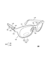
- FIG. 1 is a perspective view showing an example of the configuration of the eyewear system 1 according to the first embodiment of the present invention.
- the eyewear system 1 includes electronic glasses 100 and a lens holder 200.
- the electronic glasses 100 is an example of the first frame of the present invention.
- the lens holder 200 is an example of the second frame of the present invention.
- the electronic glasses 100 are eyewear including an electronic lens 110 including an optical property changing region in which an optical property is changed by electronic control, and a frame 120 that holds the electronic lens 110.
- the eyewear may be configured to hold an auxiliary mechanism for improving visual acuity or visibility or a mechanism for presenting information to the eye by being worn, and is worn on both ears. It is not limited to the eyeglass type, and may be a device worn only on the head or one ear. Moreover, it may be for only one eye, not for both eyes.
- the eyewear of the present invention includes various devices (for example, glasses-type wearable terminals, head mounted displays, etc.) having a mechanism for presenting information to the user's field of view or eyes.
- the electronic glasses 100 for both eyes having a pair of lenses will be described as an example of the first frame of the present invention.
- the first frame of the present invention is not limited to this.
- the front and rear, left and right, and up and down directions shown in FIG. 1 correspond to the front and rear, left and right, and up and down directions for the user wearing the electronic glasses 100, respectively.
- the eyewear system 1 will be described using the front, rear, left, and right directions shown in FIG.
- FIG. 2 is a perspective view showing an example of the configuration of the electronic glasses 100.
- the electronic glasses 100 includes the pair of electronic lenses 110 and the frame 120.
- the frame 120 has a front 130 and a pair of temples 140.
- the electron lens 110 is an example of the first lens of the present invention.
- the pair of electron lenses 110 are formed so as to be symmetric when the electronic glasses 100 are viewed from the front, and have the same components.
- the electron lens 110 includes a first region 111 whose optical characteristics can be changed by electronic control or the like, and a second region 112 that is a region other than the first region 111.
- the first region 111 is an example of the optical property changing region of the present invention. Examples of optical characteristics that change in the first region 111 include refractive index, color, polarization state, light transmittance, and the like.
- the second region 112 other than the first region 111 in the electron lens 110 is a region where the optical characteristics do not change.
- the shape and size of the first region 111 and the position with respect to the entire electronic lens 110 can be appropriately designed according to the size of the electronic lens 110, the use of the electronic glasses 100, and the like.
- Examples of the shape of the first region 111 include a circular shape and an elliptical shape.
- the shape of the first region 111 is an elliptical shape whose major axis is the left-right direction of the electronic glasses 100. Further, as shown in FIG. 2, the first region 111 is disposed below the central portion of the electronic lens 110 when the electronic lens 110 is viewed from the front.
- the structure of the electron lens 110 is, for example, as follows.
- the structure in the first region 111 of the electron lens 110 is a multilayer structure, and includes at least a liquid crystal layer (not shown) and a pair of conductive layers (not shown) sandwiching the liquid crystal layer from the front and the back.
- the structure of the electron lens 110 in the second region 112 is configured by, for example, a spherical lens or an aspherical lens having a predetermined power (including a case where there is no degree).
- the electron lens 110 is configured to have the first region 111 and the second region 112 by combining different structures. Note that the frequency of the first region 111 in a state where the optical characteristics are not changed may be the same as the frequency of the second region 112 or may be a predetermined frequency different from the frequency of the second region 112. Good.
- a pair of electrodes (not shown) for supplying electricity to the first region 111 are provided inside the electron lens 110, and each electrode is connected to the first region 111.
- the pair of electrodes is connected to the battery 160 described later through wiring arranged in the frame 120 or the like.
- the electrode include a transparent electrode such as ITO.
- the optical characteristics in the second region 112 other than the first region 111 of the electron lens 110 do not change has been described.
- the optical property of the second region 112 is described. It may also be included when the characteristics change.
- the change in the optical characteristics in the second region 112 is preferably different from the change in the optical properties in the first region 111.
- the front 130 includes a pair of rims 131 that respectively support a pair of electron lenses 110 and a bridge 132 that connects the pair of rims 131 to each other.
- the front 130 is an example of a first front frame of the present invention.
- the shape of the rim 131 is a shape corresponding to the shape of the electron lens 110.
- the bridge 132 has a pair of nose pads 133 that can contact the user's nose.
- wiring for electrically connecting an electrode of the electron lens 110 and a control unit 150 (described later) is disposed inside the front 130.
- the front 130 has armor 134 in the vicinity of both ends thereof.
- the armor 134 is a portion extending toward the left or right and rearward when viewed from the rim 131.
- the rear tip of the armor 134 is connected to the temple 140 by a hinge 141.
- the temple 140 is an example of the first temple of the present invention.
- the material of the front 130 is not particularly limited, but a material having thermoplasticity and capable of adjusting the position and shape of each part as required is preferable.
- a known material used as a front material of glasses can be used.
- the material of the front 130 include polyamide, acetate, carbon, celluloid, polyetherimide, and urethane.
- the pair of left and right temples 140 are formed so as to have a substantially symmetrical outer shape in the electronic glasses 100. As shown in FIG. 2, the temple 140 is rotatably connected to the front 130 at the hinge 141 at the front end thereof. In addition, the front or back in description of the following temple 140 means the front or back in the state (state shown by FIG. 2 etc.) which the temple 140 was expand
- the material of the temple 140 is not particularly limited, but a material having thermoplasticity and capable of adjusting the position and shape of each part as necessary is preferable.
- a known material used as a material of a temple of a general eyeglass for example, the same material as that of the material of the front 130 can be used.
- an ear hook 142 is formed Near the rear end of the temple 140.
- a battery 160 (see FIG. 3 described later) for supplying electricity to the electron lens 110 is attached to the rear end of the ear hook 142.
- other electronic components may be attached to the rear end of the ear hook 142. Examples of other electronic components include, for example, a memory for storing various information, a transceiver unit for wireless communication (Wi-Fi (registered trademark), Bluetooth (registered trademark), NFC, etc.), a camera, a microphone, a bone conduction speaker, Includes hearing aids.
- an input unit 143 is provided near the front end of the temple 140.
- the input unit 143 is a part that can be touched by a user's finger or the like for the operation of the electronic glasses 100, for example.
- at least a part of the input unit 143 is disposed so as to be exposed to the outside of the temple 140.
- the input unit 143 is preferably arranged at a position where the user of the electronic glasses 100 can easily touch the input unit 143. From such a viewpoint, the input unit 143 is disposed on the front side of the middle point of the temple 140 in the long axis direction. In addition, the input unit 143 is disposed on the outer surface of the temple 140 when viewed from the user of the electronic glasses 100. In FIG. 2, the input unit 143 is provided on the right temple 140, but may be provided on the left temple 140 or both.
- the shape of the input unit 143 is not particularly limited.
- the input unit 143 is formed in a horizontally long and substantially rectangular shape, and extends along the long axis direction of the temple 140.
- the input unit 143 is, for example, a capacitive touch sensor, and is connected to the control unit 150 as shown in FIG. That is, the input unit 143 has conductivity, and when an object (such as a user's finger) that is a conductor contacts the input unit 143, the control unit 150 can detect the contact.
- Examples of the material of the input unit 143 include gold, silver, copper, aluminum, and alloys thereof. In this case, it is preferable that the material of at least the peripheral part (for example, the temple 140) of the input part 143 is insulative.
- the input unit 143 is not limited to a capacitive touch sensor, and may be a mechanical switch, for example.
- the control unit 150 is configured by, for example, a CPU and controls whether or not the optical characteristics of the first region 111 of the electronic lens 110 are changed.
- FIG. 3 is a block diagram illustrating a functional configuration of the electronic glasses 100. As shown in FIG. 3, in the electronic glasses 100, the electronic lens 110, the input unit 143 of the temple 140, the control unit 150, and the battery 160 are electrically connected.
- the control unit 150 detects a change in capacitance at the input unit 143, and applies a voltage to the first region 111 of the electronic lens 110 when the change is detected. Specifically, for example, when the input unit 143 detects the contact of the object, the control unit 150 performs control to apply a voltage to the first region 111 or stop the application of the voltage. The optical characteristics of the region 111 are changed.
- control unit 150 may be accommodated in the vicinity of the front end portion of the temple 140, for example.
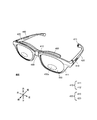
- FIG. 4A and 4B are diagrams for explaining the lens holder 200.
- FIG. 4A shows a state when the lens holder 200 is viewed from the front side
- FIG. 4B shows a state when the lens holder 200 is viewed from the rear side.
- the lens holder 200 is not particularly limited as long as at least one lens unit 300 is disposed on the object plane side of the electronic lens 110 of the electronic glasses 100 and the position thereof can be adjusted.
- the lens holder 200 is manufactured by Hasegawa Biko Co., Ltd. A trial attachment can be used.
- the lens holder 200 has a pair of holding portions 210, a position adjusting portion 220, and an attachment portion 230. As shown in FIG. 1, the lens holder 200 is used by being attached to the electronic glasses 100 from the objective surface side of the electronic lens 110 of the electronic glasses 100.
- the holding unit 210 holds a lens unit 300 with a frame, which is different from the electronic lens 110 of the electronic glasses 100 described above. More specifically, as shown in FIG. 4A, the holding part 210 includes an outer frame part 211, a first support part 212, and a second support part 213.
- the lens unit 300 is a lens in which a single lens, generally called an optometry lens, a trial lens, or the like, is housed in a frame.
- FIG. 5 is a diagram for explaining the lens unit 300. As shown in FIG. 5, the lens unit 300 includes a lens 310, a frame part 320, and a knob part 330.
- the lens 310 is an example of the second lens of the present invention.
- the lens 310 of the lens unit 300 is a normal lens that does not have a region where the optical characteristics change.
- the lens unit 300 does not need to be specially designed for the eyewear system 1, and a commercially available optometry lens or the like may be used as appropriate.
- the lens unit 300 may have the area
- the knob section 330 may be provided with an input section that changes the optical characteristics of the lens.
- the lens 310 is, for example, a myopic lens, a farsighted lens, an astigmatic lens, a color lens, a polarizing lens, a dimming lens, an anti-glare lens, a light having a specific wavelength (for example, a light having a wavelength in the vicinity of 380 to 420 nm)
- Various lenses such as a lens to reduce, a lens to reduce the transmission of light having a wavelength near 460 nm to 480 nm, a lens to reduce the transmission of light having a wavelength near 585 nm, and a specific wavelength cut lens to reduce the transmission of light. It is appropriately selected depending on the purpose.
- the lens unit 300 is supported by the first support part 212 and the second support part 213 of the holding part 210 and is held in a state of being positioned with respect to the outer frame part 211.
- the lens unit 300 is held by the holding unit 210 when the first support unit 212 and the second support unit 213 are in contact with the frame unit 320.
- the first support part 212 and the second support part 213 are formed in such a shape that the lens unit 300 can be easily attached and detached.
- the lens unit 300 is attached to the holding unit 210 by, for example, a user holding the knob unit 330 and inserting the frame unit 320 of the lens unit 300 between the first support unit 212 and the second support unit 213. Removal of the lens unit 300 from the holding unit 210 is performed, for example, by a user holding the knob unit 330 and pulling the lens unit 300 from between the first support unit 212 and the second support unit 213.
- the shape of the inner peripheral surfaces of the first support portion 212 and the second support portion 213 can favorably support the lens unit 300 according to the shape of the frame portion 320 of the lens unit 300 held by the holding portion 210, and can be attached and detached. May be formed so as to be easy.
- the inner peripheral surface of the first support part 212 or the second support part 213 is the first support part 212 or the second support that the frame part 320 contacts in the state where the lens unit 300 is held by the holding part 210.
- the surface of the part 213 is meant. In the example shown in FIG.
- the inner peripheral surface of the first support portion 212 is formed in an arc shape in accordance with the shape of the frame portion 320 of the lens unit 300 whose outer periphery is circular as shown in FIG.
- the shape of the inner peripheral surface of the second support portion 213 is similarly formed in an arc shape, but in order to make the lens unit 300 easy to attach and detach, it is formed shorter in the circumferential direction than the first support portion 212. ing.
- the first support part 212 and the second support part 213 are formed so as to support one lens unit 300, but the present invention is not limited to this, and a plurality of The lens unit 300 may be formed so as to be supported.
- the plurality of lens units 300 supported by the first support part 212 and the second support part 213 are overlapped in the front-rear direction and are held in close contact with each other. Accordingly, a plurality of lens units 300 having different properties depending on the purpose can be used in combination.
- FIG. 6A is a perspective view showing the lens holder 200 when two pairs of the first support portion 212 and the second support portion 213 are provided along the front-rear direction.
- FIG. 6B is a diagram showing a state in which two lens units 300 are inserted into the lens holder 200 in which two sets of the first support portion 212 and the second support portion 213 are provided along the front-rear direction. .
- the lens holder 200 and the lens unit 300 are viewed from above.
- the scales in the left-right direction and the front-rear direction are not accurate, and the respective parts are particularly emphasized in the front-rear direction.
- two lenses having different properties such as a myopic lens and an astigmatic lens are used. They are overlapped in the front-rear direction and held in close contact with each other.
- combinations of two lenses having different properties include, for example, a myopia lens or a farsighted lens and an astigmatism lens, a myopia lens or a farsighted lens and a color lens, a polarizing lens, a dimming lens, and an anti-glare lens.
- the combination with a lens or a specific wavelength cut lens is mentioned.
- the first support part 212 and the second support part 213 may be provided in groups of three so that the three lens units 300 can be supported. In that case, three lenses having different properties can be held simultaneously. In that case, for example, in addition to a nearsighted lens or a farsighted lens and an astigmatic lens, a color lens, a polarizing lens, a light control lens, an anti-glare lens, or a specific wavelength cut lens are superimposed in the front-rear direction and are in close contact with each other or close to each other Can be held in a state.
- the outer frame 211 is provided with a scale indicating the angle so that the angle of the lens unit 300 can be adjusted when the lens unit 300 is supported by the first support 212 and the second support 213. Good.
- the outer frame 211 has a scale (0, 30, 60, 90, 120, 150, 180) that can be measured up to 180 degrees with the left side in the horizontal direction as a reference (0 degrees). ing.
- Such a scale is used, for example, to rotate the lens 310 of the astigmatic lens unit 300 around the central axis in accordance with the astigmatism state of the user.
- the lens 310 of at least one lens unit 300 can be rotated around the central axis. What is necessary is just to be comprised.
- the first support part 212 and the second support part 213 are fixed to the outer frame part 211.
- the outer frame portion 211 has an arm portion 2112.
- the arm portion 2112 is a flat plate-like member and is connected to the position adjusting portion 220.
- the position of the arm part 2112 is adjusted by the position adjusting part 220, so that the position of the entire holding part 210 is adjusted.
- the shape of the arm portion 2112 may not be a flat plate shape, and may be, for example, a rod shape.
- the position adjusting unit 220 is a configuration for adjusting the position of the holding unit 210.
- the position adjustment unit 220 is an example of a second lens position adjustment unit of the present invention.
- the position adjustment unit 220 includes an arm unit holding unit 221, a beam unit 222, and a gear unit 223.
- the arm holding portion 221 is a cylindrical member into which the plate-like arm portion 2112 is inserted, and the arm portion 2112 extending in the vertical direction can be moved in the vertical direction. Hold.
- the inner peripheral surface of the arm portion holding portion 221 is formed to have a size so as to be in close contact with the outer peripheral surface of the arm portion 2112, and the arm portion holding portion 221 holds the arm portion 2112 by its frictional force.
- a plurality of convex portions are respectively provided on the inner peripheral surface of the arm portion holding portion 221 and the outer peripheral surface of the arm portion 2112, and the convex portion of the arm portion holding portion 221 and the convex portion of the arm portion 2112 mesh with each other.
- the arm holding unit 221 may hold the arm 2112 more firmly.
- the plurality of convex portions may be provided on at least one of the inner surfaces of the arm holding portion 221 and at least one of the outer peripheral surfaces of the arm portions 2112 facing this surface.
- the movement of the arm part 2112 in the vertical direction relative to the arm part holding part 221 may be performed by the user pinching and moving a part of the arm part 2112 protruding from the upper side of the arm part holding part 221.
- the arm portion 2112 may have a scale so that the amount of movement in the vertical direction can be understood.
- the arm holding part 221 is connected to the beam part 222 so as to be movable in the left-right direction.
- the beam portion 222 is a member having, for example, a square bar shape extending in the left-right direction.
- the beam portion 222 may not be a square bar shape, and may be, for example, a round bar shape.
- a plurality of convex portions are provided on the upper surface of the beam portion 222, and some of the convex portions mesh with a part of the gear of the gear portion 223 provided rotatably on the arm portion holding portion 221. Yes.
- One end portion of the gear portion 223 in the front-rear direction is formed in a disc shape so that the gear portion 223 can be rotated by a user, and the gear portion 223 connected integrally with the disc by the user rotating the disc. , And accordingly, the arm holding portion 221 moves in the left-right direction along the beam portion 222.
- the beam portion 222 may be marked with a number indicating the length from the left and right ends so that the amount of movement in the left-right direction can be understood. In the example shown in FIG. 4A, the number “25” is marked at a position where the distance from the end portion is 25 mm in the beam portion 222.
- the position of the holding unit 210 can be adjusted vertically and horizontally with respect to the beam unit 222 by the position adjusting unit 220.
- the other holding unit 210 has the same configuration.
- the other holding unit 210 is configured symmetrically with respect to the one holding unit 210.
- a mounting portion 230 for attaching the lens holder 200 to the electronic glasses 100 is connected to the central portion of the beam portion 222.
- the attachment portion 230 can attach the lens holder 200 to the electronic glasses 100 so that the position of the beam portion 222 is uniquely determined. Thereby, the position of the pair of holding units 210 in the vertical direction and the horizontal direction can be suitably adjusted with respect to the electronic glasses 100 by the position adjusting unit 220 described above.
- the position adjustment unit 220 may include a first movable unit 224 (see FIG. 9A) described later.
- the 1st movable part 224 is an example of the curve adjustment part of this invention.
- the first movable part 224 is provided near the center of the beam part 222, for example, and includes a movable axis substantially along the vertical direction of the electronic glasses 100.
- the first movable part 224 is a hinge, for example. With the first movable portion 224 as the rotation center (movable center), the beam portions 222 on both sides of the first movable portion 224 can be adjusted to a desired angle.
- the first movable portion 224 is configured to yaw the left and right beam portions 222 and the holding portion 210 fixed to the beam portions 222.
- the first movable part 224 is not limited to a hinge, and may be configured to be adjustable according to the curve of the front 130 of the electronic glasses 100.
- the first movable part 224 may have a bellows structure.
- the position adjustment unit 220 may include a second movable unit 225 (see FIG. 9B) described later.
- the 2nd movable part 225 is an example of the inclination adjustment part of this invention.
- the second movable portion 225 is provided, for example, in the vicinity of a connection portion (a later-described connection portion 231) between the beam portion 222 and the attachment portion 230, and includes a movable shaft substantially along the left-right direction of the electronic glasses 100.
- the second movable part 225 is, for example, a hinge. With the second movable portion 225 as the rotation center (movable center), the entire beam portion 222 can be adjusted to a desired angle.
- the second movable part 225 is configured to pitch the beam part 222 and the entire holding part 210.
- the second movable part 225 is not limited to a hinge, and may be configured to be adjustable according to the inclination of the electronic lens 110 of the electronic glasses 100, and may have a bellows structure, for example.
- the second movable unit 225 when the electronic lens 110 of the electronic glasses 100 is provided to be inclined in the front-rear direction, the lens surface of the lens 310 of the lens unit 300 held by the holding unit 210 is The angle can be adjusted according to the inclination of the front 130 of the electronic glasses 100 so as to face the lens surface of the electronic lens 110 of the electronic glasses 100.
- the position adjustment unit 220 may include both the first movable unit 224 and the second movable unit 225 described above.
- the first movable portion 224 and the second movable portion 224 are arranged so that the lens surface of the lens 310 (second lens) of the lens unit 300 faces the lens surface of the electronic lens 110 (first lens) of the electronic glasses 100 horizontally.
- the movable unit 225 may work in cooperation with the angle adjusting unit that adjusts the angle of the lens surface of the lens 310 of the lens unit 300.
- the attachment portion 230 includes a connection portion 231, a shaft member 232, an upward claw portion 233, an attachment beam portion 234, a spring 235, and a pair of downward claw portions 236.
- the attachment part 230 is an example of a second attachment part of the present invention.
- connection portion 231 is a member that connects the upper end of the shaft member 232 and the central portion of the beam portion 222.
- the shaft member 232 is a rod-shaped member that extends in the vertical direction.
- An upward claw portion 233 is provided at the lower end of the shaft member 232.
- a mounting beam portion 234 extending substantially in the horizontal direction is provided so as to be movable in the vertical direction. More specifically, the shaft member 232 is fitted into a hole (not shown) provided in the central portion of the mounting beam portion 234, and the diameter of the hole is formed to be slightly larger than the diameter of the shaft member 232. Thus, the mounting beam portion 234 can move in the vertical direction with respect to the shaft member 232.
- a grip portion 2341 for a user to grip at the time of attachment is provided at the center portion of the attachment beam portion 234 so as to protrude forward, for example.
- a spring 235 is provided between the connecting portion 231 and the mounting beam portion 234 so as to surround the shaft member 232.
- the mounting beam portion 234 is urged downward by the spring 235 with respect to the connection portion 231.
- a pair of downward claw portions 236 are provided on the left and right ends of the mounting beam portion 234.
- a method of attaching the lens holder 200 to the electronic glasses 100 using such an attachment part 230 is as follows.
- the mounting beam portion 234 and the pair of downward claws 236 move upward, and the pair of downward claws 236 and the upward claws
- a gap is formed between the 233 and 233.
- the biasing force of the spring 235 lowers the mounting beam portion 234 and the pair of downward claws 236.
- Directional force is applied.
- the front 130 of the electronic glasses 100 is sandwiched between the upward claw portion 233 and the pair of downward claw portions 236.
- the lens holder 200 is supported at three points with respect to the frame 120 of the electronic glasses 100, the lens holder 200 is attached so as not to move with respect to the electronic glasses 100.
- the mounting portion 230 in which the front 130 of the electronic glasses 100 is sandwiched between the upward claw portion 233 and the pair of downward claw portions 236 has been described, but the present invention is not limited to this.
- a clip-like member urged in the closing direction by a spring may be employed as the attachment portion 230.
- the clip-shaped member is covered with a soft material (resin or the like) so that the electronic glasses 100 are not damaged by the clip-shaped member.
- the eyewear system 1 is used with the lens holder 200 attached to the electronic glasses 100.
- the eyewear system 1 is mainly used for the purpose of allowing a user to experience a difference in appearance due to a change in optical characteristics in the first region 111 of the electronic glasses 100.
- a user who experiences is described as an experiencer.
- the electronic lens 110 of the experience electronic glasses 100 has no degree or is adjusted to a predetermined power (including progressive design), and is not adapted to the visual acuity of the user. For this reason, when the experience person with reduced visual acuity wears the electronic glasses 100 for experience, the experience person sees the surroundings through a lens that does not match his / her vision. For this reason, the experienced person often cannot obtain a good view through the electronic glasses 100. Even if the optical characteristics of the first region 111 that is a part of the electron lens 110 change in this state, it is difficult for the experience person to recognize the difference in appearance in the first region 111.
- the lens unit 300 having a power matching the visual acuity of the experiencer is attached to the lens holder 200, thereby giving a clear view to the experiencer.
- the experiencer can preferably experience the difference in appearance due to the change in the optical characteristics in the first region 111.
- the electronic glasses 100 using the eyewear system 1 When an experienced person experiences the electronic glasses 100 using the eyewear system 1, first, the electronic glasses 100 to which the lens holder 200 is attached are put on by the experienced person.
- FIG. 7 is a diagram illustrating a state in which the lens unit 300 that matches the visual acuity of the experience person is attached to the lens holder 200.
- the lens unit 300 adapted to the visual acuity of the experience person is a myopia lens having a frequency suitable for the visual acuity, for example, when the experience person is myopia.
- the lens is a hyperopic lens with a frequency suitable for visual acuity.
- the lens unit 300 having an astigmatism lens is attached to the lens holder 200 at an angle that matches the axial angle of the astigmatism of the experience person.
- the power of the nearsighted or farsighted lens may be determined according to the power of the lens used in the glasses, for example, when the experienced person already uses the glasses.
- the lens holder 200 can hold a plurality of lenses
- a plurality of lenses can be combined. That is, when an experience person has myopia or hyperopia and astigmatism at the same time, the lens unit 300 having an astigmatism lens is attached to the lens holder 200 at the same time as the lens unit 300 having a myopia or hyperopia lens.
- a combination may be attached to the lens holder 200.
- the lens unit 300 is preferably attached to the lens holder 200 by, for example, a shop clerk who allows the experiencer to experience the eyewear system 1, but may be performed by the experiencer himself.
- FIG. 8A is a diagram illustrating a state of the position adjustment of the lens unit 300 as viewed from the front.
- FIG. 8B is a side view of the relationship between the position adjustment of the lens unit 300 and the field of view of the experience person.
- the upper side of the arrow indicates the state before the position adjustment
- the lower side of the arrow indicates the state after the position adjustment.
- the scales in the left-right direction and the front-rear direction are not accurate, and each part is particularly emphasized in the front-rear direction.
- 8A and 8B show the positional relationship between the first region 111 of the electronic glasses 100 and the lens 310 of the lens unit 300, and the lens holder 200 is not shown.
- the position adjustment of the lens unit 300 is preferably performed by a shop clerk or the like, but may be performed by an experienced person himself.
- the position adjustment of the lens unit 300 is performed so that the first region 111 is located in the field of view through the lens 310 of the lens unit 300 of the experience person.
- the lens unit 300 is moved in the protruding direction.
- the position of the lens unit 300 may be finely adjusted as appropriate so that the first region 111 is in a more suitable position for the experience person in the field of view FV through the experience person's lens 310.
- the first region 111 can be positioned in the field of view that matches the visual acuity of the experience person.
- the experiencer can preferably experience the difference in appearance due to the change in the optical characteristics in the first region 111. It is more preferable that the operation of the input unit 143 is performed by an experienced person himself rather than a shop clerk.
- the position adjusting unit 220 of the lens holder 200 has the first movable unit 224, even if the front 130 of the electronic glasses 100 is curved as shown in FIG. 9A, it is held by the holding unit 210.
- the position of the lens 310 to be adjusted can be adjusted according to the curve.
- the position adjustment unit 220 of the lens holder 200 has the second movable unit 225, as shown in FIG. 9B, even if the electronic lens 110 of the electronic glasses 100 is tilted in the front-rear direction, the lens 310 Can be adjusted in accordance with the inclination of the electron lens 110.
- the experiencer can more suitably experience the difference in appearance due to the change in the optical characteristics in the first region 111.
- the eyewear system 1 includes the electronic lens 110 (first lens) including the first region 111 (optical property changing region) in which the optical characteristics change, and the electronic lens.
- the electronic glasses 100 (eyewear) including the frame 120 for holding 110, and the lens 310 (second lens) of the lens unit 300 different from the electronic lens 110 are directly opposed to one surface of the electronic lens 110, and the electronic A holding unit 210 that holds the lens unit 300 so that the first region 111 is positioned in the field of view through the lens 310 of the user (user) wearing the glasses 100, and an attachment unit 230 that is attached to the frame 120.
- Lens holder 200 the electronic lens 110 (first lens) including the first region 111 (optical property changing region) in which the optical characteristics change
- the electronic glasses 100 including the frame 120 for holding 110, and the lens 310 (second lens) of the lens unit 300 different from the electronic lens 110 are directly opposed to one surface of the electronic lens 110, and the electronic A holding unit 210 that holds the lens unit 300 so that the first region 111 is positioned in the field
- the first region 111 is positioned in the field of view through the lens 310 that matches the visual acuity of the experience person. Will be able to.
- the experiencer can preferably experience the difference in appearance due to the change in the optical characteristics of the first region 111.
- the lens holder 200 includes a position adjusting unit 220 that adjusts the relative position of the lens unit 300 with respect to the electronic lens 110.
- the position adjustment unit 220 adjusts the position of the lens unit 300 to thereby adjust the visual acuity of the experience person.
- the first region 111 can be positioned in the field of view that matches the above.
- the position of the lens unit 300 can be adjusted as appropriate so that the position of the lens 310 is suitable for the experience person.
- a lens holder that holds a lens unit of a predetermined frequency is attached to electronic glasses having an electronic lens, thereby experiencing a difference in appearance due to a change in optical characteristics of the electronic lens.
- the eyewear system that people experienced.
- the eyewear system allows the experiencer to experience the difference in appearance due to the change in the optical characteristics of the electronic lens by attaching the overglass having the electronic lens to his / her glasses.
- the overglass means eyewear that is attached in a form that covers other eyewear.
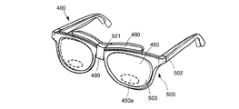
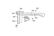
- FIG. 10 and 11 are views illustrating the appearance of the overglass 400 according to the second embodiment.
- the over glass 400 is an example of the first frame of the present invention.
- FIG. 10 is a perspective view of the overglass 400 as viewed from the front
- FIG. 11 is a perspective view of the overglass 400 as viewed from the rear.
- the front-rear direction, the vertical direction, and the left-right direction of the overglass 400 correspond to the front-rear direction, the vertical direction, and the left-right direction with respect to the face of the user wearing the overglass 400, respectively. .
- the X-axis direction in each drawing is the front-rear direction (the direction indicated by the arrow is the front), the Y-axis direction is the left-right direction (the direction indicated by the arrow is the left), and the Z-axis direction is the vertical direction (the direction indicated by the arrow) Is upper).
- the over glass 400 includes a frame 430, an input unit 440, an electronic lens 450, a control unit 460, a power source 470, a mounting unit 480, and a position adjusting unit 490.
- the attachment portion 480 is an example of the first attachment portion of the present invention.
- the position adjustment unit 490 is an example of the first lens position adjustment unit of the present invention.
- the frame 430 has a front 410 and a pair of temples 420.
- the front 410 holds a pair of electronic lenses 450. Each of the pair of electronic lenses 450 corresponds to the left and right eyes of the experience person.
- the front 410 includes a pair of rims 411 that respectively support the pair of electron lenses 450, and a bridge 412 that connects the pair of rims 411.
- the shape of the rim 411 corresponds to the shape of the electron lens 450.
- wiring for electrically connecting the electronic lens 450 and the control unit 460 is disposed inside the front 410 (between the rim 411 and the electronic lens 450).
- the front 410 includes an attachment portion 480 for attaching the overglass 400 to the experience glasses when the overglass 400 is used together with the experience glasses.
- the mounting portion 480 is disposed on the upper portion of the front 410 in the vicinity of the substantially central portion of the front 410 (that is, the central portion of the overglass 400 in the left-right direction) along the shape of the front 410. It is a member.
- the attachment portion 480 does not need to be connected to the front 410 as a whole, and only a part of the mounting portion 480 needs to be connected to the front 410.
- 10 and 11 show an example in which the attachment portion 480 is connected to the front 410 only in the vicinity of the bridge 412.
- the front 410 includes a position adjusting unit 490 for adjusting the position of the electronic lens 450 with respect to the lens of the experience glasses when the overglass 400 is used together with the experience glasses.
- the position adjustment portion 490 is disposed at a position where the attachment portion 480 is connected to the front 410. Details of the attachment portion 480 and the position adjustment portion 490 will be described later.
- the material of the front 410 is not particularly limited, and a known material that is generally used as a front material of glasses can be employed.
- the material of the front 410 may be appropriately selected from, for example, metals such as titanium, aluminum, and stainless steel, resins such as polyamide, acetate, celluloid, polyetherimide, and polyurethane, or carbon.
- the pair of temples 420 are a pair of rod-like members arranged so as to be substantially symmetrical and are connected to the front 410 at the front end portions thereof.
- An input unit 440 is disposed on one or both of the pair of temples 420.
- a control unit 460 is disposed on one of the pair of temples 420.
- a power source 470 is disposed at one or both terminal portions (end portions far from the front 410) of the pair of temples 420.
- wiring for electrically connecting the input unit 440, the control unit 460, and the power source 470 is arranged inside the temple 420.
- the material of the temple 420 is not particularly limited, and may be a known material used as a temple material for glasses.
- the material of the temple 420 is appropriately selected from, for example, metals such as titanium, aluminum and stainless steel, resins such as polyamide, acetate, celluloid, polyetherimide and polyurethane, or carbon.
- the members constituting the appearance of the overglass 400 that is, the frame 430 and the electronic lens 450 including the front 410 and the temple 420 are formed and arranged so as to be almost symmetrical with respect to the center of the frame 430.
- the input unit 440 receives an input operation from an experienced person wearing the overglass 400 or the like.
- the input unit 440 is a plurality of capacitive touch sensors arranged in the region outside and in front of the temple 420.
- the input unit 440 may be a sensor other than a touch sensor, and the number of sensor devices may be one or more.
- the pair of electron lenses 450 is a lens having a liquid crystal lens 450 a that is held on the front 410 of the frame 430 and whose optical characteristics change by application of voltage.
- the electron lens 450 may be a spherical lens or an aspheric lens.
- the electron lens 450 has a multilayer structure in which a plurality of layers overlap in the thickness direction.
- Part of the multilayer structure is a liquid crystal lens 450a having a liquid crystal layer (not shown) sandwiched between a pair of conductive layers (not shown).
- the liquid crystal lens 450 a occupies a part of the electron lens 450.
- a transparent electrode (not shown) is connected to the pair of conductive layers, and the liquid crystal lens 450a is electrically connected to the control unit 460 via the transparent electrode.
- the liquid crystal lens 450 a can change the refractive index when a voltage is applied between the pair of conductive layers under the control of the control unit 460 according to an input operation to the input unit 440.
- the liquid crystal lens 450a is an example of the electric element and the optical element of the present invention.
- the control unit 460 controls the operation or non-operation of the liquid crystal lens 450a according to the input operation received by the input unit 440.
- the control unit 460 is an arithmetic unit including, for example, a CPU (Central Processing Unit), a RAM (Random Access Memory), a ROM (Read Only Memory), and the like.
- the control unit 460 reads a program for executing the function of the liquid crystal lens 450a from the ROM, expands it in the RAM, and controls the operation of the liquid crystal lens 450a that executes the expanded program.
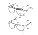
- FIG. 12A and FIG. 12B are diagrams illustrating a state in which the overglass 400 is used together with the experience person glasses 500.
- the experienced person glasses 500 have lenses having a power that matches the visual acuity of the experienced person who wants to experience the electronic lens 450 of the overglass 400, for example.
- the experience person glasses 500 is an example of the second frame of the present invention.
- FIG. 12A is a perspective view illustrating the state before the overglass 400 is attached to the experience glasses 500
- FIG. 12B is a perspective view illustrating the state after the overglass 400 is attached to the experience glasses 500.
- the overglass 400 is attached to the experience glasses 500 when the attachment portion 480 of the overglass 400 comes in contact with the upper side of the front 501 of the experience glasses 500 as shown in FIG. It means that the glass 400 is held. That is, in the present embodiment, the state where the overglass 400 is attached to the experience glasses 500 is a state where the overglass 400 is placed on the front 501 of the experience glasses 500 by the attachment portion 480.
- the front 501 is an example of the second front frame of the present invention.
- the parts other than the attachment portion 480 of the overglass 400 may or may not contact the experience person glasses 500. From the viewpoint of dispersing the weight of the overglass 400, for example, it is preferable that a part of the temple 420 of the overglass 400 is in contact with the temple 502 of the experience glasses 500.
- the temple 502 is an example of the second temple of the present invention.
- the state where the overglass 400 is attached to the experience glasses 500 may be a state where the over glasses 400 are fixed to the experience glasses 500 or a state where the over glasses 400 are not fixed.
- “fixed” means that the overglass 400 cannot be easily removed from the experience glasses 500 by, for example, clipping or screwing.
- various overglasses 400 having different addition powers of the liquid crystal lens 450a can be easily replaced. It is more suitable because it can be experienced by an experienced person.
- the overglass 400 when the overglass 400 is attached to the experience glasses 500, the electronic lens 450 of the overglass 400 and the lens 503 of the experience glasses 500 overlap each other. Thereby, the experience person can experience the view through both the lens 503 of the experience person glasses 500 and the liquid crystal lens 450a of the over glass 400. For this reason, even an experienced person with low vision can suitably experience the change in appearance by the liquid crystal lens 450a of the overglass 400.
- the liquid crystal lens 450a may not be in a suitable position as described later.
- the overglass 400 includes a position adjusting unit 490.
- the front 410 of the overglass 400 is provided with a position adjusting unit 490 for adjusting the position of the electronic lens 450 with respect to the experience glasses 500.
- the position adjustment unit 490 enables the position adjustment of the electronic lens 450 with respect to the lens 503 of the experience person glasses 500.
- a method for realizing the position adjustment of the position adjustment unit 490 is not particularly limited in the present invention.
- the position adjustment may be performed by the following method, for example. That is, the position adjusting unit 490 has a position adjusting mechanism such as a screw or a rail, and is configured to be able to adjust the position of the electronic lens 450 with respect to the mounting unit 480 by rotating the screw or sliding the rail. That's fine. With this configuration, the position of the electronic lens 450 with respect to the lens 503 of the experiencer glasses 500 can be adjusted.
- the position adjustment unit 490 is disposed substantially at the center in the left-right direction of the overglass 400.
- the position adjustment unit 490 can perform position adjustment in three directions.
- the three directions are the front-rear direction, the left-right direction, and the up-down direction.
- the front-rear direction is an example of the direction in which the electronic lens 450 approaches or moves away from the lens 503 of the experiencer glasses 500 (first direction of the present invention).
- the left-right direction and the up-down direction are examples of a direction (second direction of the present invention) orthogonal to the first direction.
- FIGS. 13A and 13B The position adjustment in the front-rear direction will be described with reference to FIGS. 13A and 13B.
- the position of the lens 503 of the experiencer glasses 500 is considered to be a suitable lens position for the experiencer.
- it is desirable that the position adjustment in the front-rear direction in a state where the overglass 400 is attached to the experiencer glasses 500 is performed in a direction in which the electronic lens 450 of the overglass 400 is as close as possible to the lens 503.
- FIG. 13A is a diagram illustrating a state before the position adjustment in the front-rear direction is performed after the overglass 400 is attached to the experiencer glasses 500.
- FIG. 13A is a diagram illustrating a state before the position adjustment in the front-rear direction is performed after the overglass 400 is attached to the experiencer glasses 500.
- FIG. 13B is a diagram illustrating a state in which the position adjustment is performed so that the electronic lens 450 approaches the lens of the experience glasses 500 in the front-rear direction of the over glasses 400 in a state where the experience glasses 500 are attached to the experience glasses 500. It is.
- An arrow A ⁇ b> 1 illustrated in FIG. 13B illustrates the moving direction in the front-rear direction of the electronic lens 450 by the position adjustment unit 490.
- the position adjustment in the front-rear direction is not limited to the adjustment in the direction in which the electronic lens 450 is brought closer to the lens 503, and in some cases, the adjustment in the direction in which the electronic lens 450 is moved away from the lens 503 may be performed.
- FIG. 14A is a diagram illustrating a state before the position adjustment in the left-right direction is performed after the overglass 400 is attached to the experiencer glasses 500.
- FIG. 14B is a diagram illustrating a state in which the position adjustment is performed in the left-right direction of the overglass 400 in a state where the overglass 400 is attached to the experiencer glasses 500.
- the human eye sees a short distance, it becomes a cross-eyed eye compared to when looking at a middle or far distance. For this reason, in the eyewear for both near and far, it is necessary to make eyepoints (positions at which the line of sight passes through the lens) differ between the short distance and the middle / long distance in the left-right direction.
- the short-distance eye point near-eye point
- far-distance eye point far-distance eye point
- the amount of deviation between the near eye point and the far eye point in the left-right direction is called inset.
- the position of the liquid crystal lens 450a matches the near eyepoint of the experiencer in the left-right direction. It is desirable to be adjusted as follows.
- An arrow A2 in FIG. 14B illustrates the moving direction of the electronic lens 450 in the left-right direction by the position adjustment unit 490.
- the position adjustment in the left-right direction is a position adjustment in a direction in which the left and right electronic lenses 450 approach or move away from the position adjustment unit 490 disposed substantially at the center in the left-right direction of the overglass 400. means. That is, the position adjustment in the left-right direction by the position adjustment unit 490 is performed substantially symmetrically with respect to the position adjustment unit 490. Thereby, the position adjustment of the pair of electron lenses 450 in the left-right direction can be easily performed.
- FIG. 15A is a diagram illustrating a state before the position adjustment in the vertical direction is performed after the overglass 400 is attached to the experiencer glasses 500.
- FIG. 15B is a diagram illustrating a state in which the position adjustment is performed in the vertical direction of the overglass 400 in a state where the overglass 400 is attached to the experiencer glasses 500.
- the liquid crystal lens 450a may protrude from the lens 503 when viewed from the experience person. Such a state can occur when the vertical length of the electron lens 450 and the vertical length of the lens 503 are different from each other. In such a case, since the liquid crystal lens 450a is not located in the field of view through the lens 503 of the experience person, it is difficult for the experience person to suitably experience the change in appearance of the overglass 400 by the electronic lens 450. is there.
- the position adjustment by the position adjustment unit 490 is performed so that the entire liquid crystal lens 450a is positioned in the field of view through the lens 503 of the experience person in the vertical direction.
- the position adjustment by the position adjustment unit 490 is desirably performed so that the liquid crystal lens 450a is positioned below the field of view through the lens 503 of the user in the vertical direction.
- a short-distance lens is often arranged from below, and other areas are often used for middle and long distances.
- FIG. 15B shows a state in which the position of the electronic lens 450 in the vertical direction is adjusted and the liquid crystal lens 450 a is adjusted so that the liquid crystal lens 450 a does not protrude from the lens 503 and is disposed below the lens 503 as viewed from the experience person.
- the position adjustment unit 490 adjusts the position in the vertical direction, and the part other than the part 480 ⁇ / b> P of the attachment unit 480 is away from the experience glasses 500.
- the part 480 ⁇ / b> P of the attachment part 480 is a part of the attachment part 480 that is not moved by the position adjustment part 490.
- the overglass 400 is attached to the experience person glasses 500 when only a part 480P of the attachment part 480 comes into contact with the experience person glasses 500.
- An arrow A3 illustrated in FIG. 15B exemplifies a moving direction in the vertical direction of the electronic lens 450 by the position adjusting unit 490.
- the position adjustment unit 490 of the overglass 400 moves other components of the overglass 400 (such as the frame 430 including the front 410 and the temple 420) together with the electronic lens 450.
- the experience person of the over glass 400 can fit the over glass 400 suitably according to the shape of the head of the experience person, using the position adjusting unit 490.
- the overglass 400 is eyewear used together with the experience glasses 500, and includes the electronic lens 450 having the liquid crystal lens 450a and the frame 430 that holds the electronic lens 450.
- a mounting unit 480 that attaches the frame 430 to the experience glasses 500, and a position adjustment unit 490 that adjusts the relative position of the electronic lens 450 with respect to the lens 503 of the experience glasses 500 while being attached to the experience glasses 500.
- the position of the electronic lens 450 relative to the lens 503 of the experience glasses 500 can be suitably adjusted. Therefore, when the overglass 400 of the present invention is used together with the experience glasses 500, the position of the liquid crystal lens 450a of the electronic lens 450 can be a suitable position in the field of view of the experience. Thereby, for example, an experienced person who uses glasses with a degree can preferably experience eyewear having an electrically controlled lens.
- the position adjustment unit 490 is arranged in a first direction that approaches or moves away from the lens 503 of the experience glasses 500 and / or a first direction orthogonal to the first direction. Adjust the relative position in the two directions.
- the first direction corresponds to, for example, the front-rear direction with respect to the face of the user wearing the overglass 400
- the second direction corresponds to the left-right direction and the up-down direction.
- the position adjustment unit 490 moves other components of the overglass 400 together with the electronic lens 450 when the position of the electronic lens 450 is adjusted.
- Other configurations of the overglass 400 refer to the frame 430 including the front 410 and the temple 420, and the like. With such a configuration, the over-glass 400 can be suitably fitted to the experience person's head shape by the position adjustment unit 490.
- the electronic glasses 100 or the overglass 400 has the pair of electronic lenses 110 or 450, but the present invention is not limited to this.
- the electronic glasses or overglass (the first frame of the present invention) may have, for example, only one electronic lens, or a lens that is not an electronic lens (for example, a lens with a degree) and one electronic lens. You may have. Depending on the case, you may have three or more lenses.
- the lens holder 200 is attached to the front side of the electronic glasses 100 as shown in FIG. 1 and the like, but the present invention is not limited to this, and the lens holder is the electronic glasses. It may be attached to the rear side. However, in this case, since the lens holder and the lens unit held by the lens holder are positioned between the electronic glasses and the eyes of the experience person, the lens holder and the lens unit are formed to be thin. It is desirable that
- the overglass 400 having the same shape as the glasses has been described as the overglass 400 as an example of the first frame, but the present invention is not limited to this.
- the temple may be shorter than the experience person glasses or may not have a temple.
- the first frame of the present invention may have a configuration including only a front and a lens. According to such a configuration, it is possible to prevent a situation in which it is difficult to remove the overglass from the experience glasses because the temple of the over glasses and the temple of the experience glasses are interfered with each other.
- an input unit that receives an input operation regarding the operation or non-operation of the liquid crystal lens may be provided, for example, at the front of the first frame.
- the state where the overglass 400 is attached to the experience glasses 500 is a state where the overglass 400 is placed on the frame (front) of the experience glasses 500 by the attachment portion 480.
- the present invention is not limited to this.
- the first frame of the present invention may have a clip member as the first attachment portion, and a method of attaching the clip frame to the front of the experience glasses from above or below may be adopted.
- the present invention is not limited to this.
- the electronic lens included in the overglass may be disposed between the eyes of the experience person and the lenses of the experience person glasses. In this case, when the position of the electronic lens is adjusted in the front-rear direction, the electronic lens is adjusted in a direction closer to the lens of the experiencer glasses (away from the experiencer's eyes) from the viewpoint of adjusting to a more suitable distance from the experiencer's eyes. It is desirable.
- the overglass 400 has been described with respect to the example having the position adjusting unit 490 that can adjust the position in the front-rear direction, the left-right direction, and the up-down direction, but the present invention is not limited to this.
- the electronic lens has a position adjusting unit capable of adjusting the position in either the first direction, which is a direction in which the electronic lens approaches or moves away from the lens of the experience glasses, or the second direction orthogonal to the first direction. If you do. That is, it is good also as a structure which can perform position adjustment only in any one of the front-back direction, the left-right direction, and the up-down direction.
- the first direction need not exactly coincide with the front-rear direction of the overglass.
- the second direction is not limited to the left-right direction or the vertical direction of the overglass, and may be a direction oblique to the left-right direction or the vertical direction.
- one position adjustment unit 490 performs position adjustment in all directions of front and rear, left and right, and up and down, but the present invention is not limited to this.
- a different position adjusting unit for each direction may be provided.
- the position adjustment unit for the front-rear direction, the position adjustment unit for the left-right direction, and the position adjustment unit for the up-down direction may be provided separately.
- the respective position adjusting units may be provided at different positions of the eyewear of the present invention.
- the position adjustment unit for the left and right direction and the position adjustment unit for the vertical direction are provided in the vicinity of the bridge, and the position adjustment unit for the front and rear direction is provided in the armor (a portion between the front and the temple), respectively. May be.
- the electronic glasses 100 and the lens holder 200 are formed separately.
- the overglass 400 and the experience person glasses 500 are formed separately.
- the present invention is not limited to this.
- the eyewear system of the present invention has an eye that is held in a state where two lenses of a first lens having an optical characteristic change region and a second lens having a predetermined power are stacked on each other. It may be a wear system. In this case, it is desirable that the position of the first lens can be adjusted with respect to the second lens.
- the first lens and the second lens are changed by changing the refractive index of the optical property changing region of the first lens. It is possible to let the experience experience the field of view through both.
- the optical characteristic change region of the first lens can be positioned at a position suitable for the experience person. For this reason, the eyewear system of the present invention can be suitably experienced even for an experienced person with low vision even when there is no glasses adapted to the vision of the experienced person.
- the electronic glasses 100 according to the first embodiment or the overglass 400 according to the second embodiment accepts an operation on the control unit 150 (460), and the refractive index of the electronic lens 110 (liquid crystal lens 450a).
- the user or operator a person other than the user who supports the user's trial use
- a notification unit for notifying by LED or sound may be provided.
- the user or operator who tries the electronic glasses 100 according to the first embodiment or the overglass 400 according to the second embodiment can use the refractive index of the electronic lens 110 (liquid crystal lens 450a). Can be recognized based on light and sound other than the change in refractive index.
- the present invention is suitable as an eyewear system that allows the user to easily experience eyewear having a lens including a region where the optical characteristics change.
Landscapes
- Physics & Mathematics (AREA)
- Health & Medical Sciences (AREA)
- Ophthalmology & Optometry (AREA)
- General Physics & Mathematics (AREA)
- Optics & Photonics (AREA)
- General Health & Medical Sciences (AREA)
- Eyeglasses (AREA)
Abstract
本発明のアイウェアシステムは、光学特性が変化する光学特性変化領域を含む第1レンズ、および前記第1レンズを保持する第1フレームと、前記第1レンズとは異なる第2レンズを保持する第2フレームと、を備え、前記第1レンズと前記第2レンズとが正対し、前記第2レンズを通した体験者の視界内に前記光学特性変化領域が位置するように、前記第1フレームは前記第1フレームを前記第2フレームに取り付けるための第1取付部を有する、または、前記第2フレームは前記第2フレームを前記第1フレームに取り付けるための第2取付部を有する。
Description
本発明は、光学特性が変化する領域を含むレンズを有するアイウェアを用いたアイウェアシステムに関する。
近年、電気的制御等により光学特性が変化する光学特性変化領域を有するレンズを備えたアイウェアが開発されている。具体的には、例えばユーザがアイウェアに設けられたスイッチを操作すると、光学特性変化領域に電気が供給され、当該領域の光学特性、例えば屈折率、色、偏光状態等が変化する。このようなアイウェアの例として、特許文献1に開示された電子眼鏡がある。
特許文献1に開示された電子眼鏡では、光学特性の変化によって見え方が大きく変わる。このため、電子眼鏡を使用したことがない新規ユーザに対して、光学特性の変化による見え方の違いを体験させたい、という要望がある。しかしながら、電子眼鏡を体験しようとするユーザの視力は一律ではなく、全てのユーザの視力に対応できる電子眼鏡をあらかじめ用意することは困難である。このため、視力が異なる様々なユーザに対して、光学特性の変化による見え方の違いを容易に体験させることができる仕組みが要望されている。
このような仕組みの例として、光学特性変化領域を有する第1のレンズと、ユーザの視力に合わせた度数を有する第2のレンズとを別々に用意し、第1のレンズと第2のレンズとを重ねた状態でユーザの目の前に配置する構成が挙げられる。
ところで、光学特性変化領域を有するレンズを備えたアイウェアを好適に体験させるためには、光学特性変化領域をユーザの視界のうちの好適な位置に位置させる必要がある。好適な位置とは、具体的には、電気素子を有するレンズが遠近両用のレンズ(電気素子の領域が近距離用、それ以外の領域が遠距離用)であった場合、例えばユーザの視界の下方よりの位置である。
しかしながら、第1のレンズと第2のレンズとを重ねた状態でユーザの目の前に配置する際、光学特性変化領域が好適な位置とならない場合がある。
本発明は、上記事情に鑑み、光学特性変化領域を有するレンズとそうでないレンズとの相対位置を調節することができるアイウェアシステムを提供することを目的とする。
本発明に係るアイウェアシステムは、光学特性が変化する光学特性変化領域を含む第1レンズ、および前記第1レンズを保持する第1フレームと、前記第1レンズとは異なる第2レンズを保持する第2フレームと、を備え、前記第1レンズと前記第2レンズとが正対し、前記第2レンズを通した体験者の視界内に前記光学特性変化領域が位置するように、前記第1フレームは前記第1フレームを前記第2フレームに取り付けるための第1取付部を有する、または、前記第2フレームは前記第2フレームを前記第1フレームに取り付けるための第2取付部を有する。
本発明によれば、光学特性変化領域を有するレンズとそうでないレンズとの相対位置を調節することができる。
(第1の実施の形態)
以下、本発明の第1の実施形態に係るアイウェアシステムについて、図面を用いて説明する。
以下、本発明の第1の実施形態に係るアイウェアシステムについて、図面を用いて説明する。
[アイウェアシステムの構成]
図1は、本発明の第1の実施の形態に係るアイウェアシステム1の構成の一例を示す斜視図である。図1に示すように、アイウェアシステム1は、電子メガネ100と、レンズ保持具200と、を有する。電子メガネ100は、本発明の第1フレームの一例である。また、レンズ保持具200は、本発明の第2フレームの一例である。
図1は、本発明の第1の実施の形態に係るアイウェアシステム1の構成の一例を示す斜視図である。図1に示すように、アイウェアシステム1は、電子メガネ100と、レンズ保持具200と、を有する。電子メガネ100は、本発明の第1フレームの一例である。また、レンズ保持具200は、本発明の第2フレームの一例である。
電子メガネ100は、電子制御により光学特性が変化する光学特性変化領域を含む電子レンズ110および電子レンズ110を保持するフレーム120を有するアイウェアである。本発明において、アイウェアとは、装着されることにより、眼に対して視力または視界向上のための補助機構や情報提示のための機構を保持する構成であればよく、両方の耳に装着されるメガネ型に限らず、頭部や片方の耳のみに装着される装置であってもよい。また、両眼用ではなく、片眼のみに作用するものであってもよい。また、本発明のアイウェアには、ユーザの視界あるいは眼に対して情報提示を行う機構を有する種々のデバイス(例えば、メガネ型ウェアラブル端末、ヘッドマウントディスプレイ等)等が含まれる。
以下説明する第1の実施の形態では、本発明の第1フレームの一例として、一対のレンズを有する、両目用の電子メガネ100について説明するが、本発明の第1フレームはこれに限定されない。
なお、図1に示す前後、左右、上下方向は、電子メガネ100を掛けたユーザにとっての前後、左右、上下方向にそれぞれ対応している。本第1の実施の形態では、図1に示す前後、左右、上下方向を用いてアイウェアシステム1の説明を行う。
[電子メガネ100の構成]
図2は、電子メガネ100の構成の一例を示す斜視図である。上記したように、電子メガネ100は、一対の電子レンズ110と、フレーム120とを有する。フレーム120は、フロント130、および一対のテンプル140を有する。電子レンズ110は、本発明の第1レンズの一例である。
図2は、電子メガネ100の構成の一例を示す斜視図である。上記したように、電子メガネ100は、一対の電子レンズ110と、フレーム120とを有する。フレーム120は、フロント130、および一対のテンプル140を有する。電子レンズ110は、本発明の第1レンズの一例である。
一対の電子レンズ110は、電子メガネ100を正面視したときに左右対称となるように形成されており、互いに同一の構成要素を有する。
電子レンズ110は、電子制御等により光学特性が変化しうる第1領域111と、第1領域111以外の領域である第2領域112とを有する。第1領域111は、本発明の光学特性変化領域の一例である。第1領域111において変化する光学特性の例には、屈折率、色、偏光状態、光の透過率等が含まれる。本第1の実施の形態において、電子レンズ110における、第1領域111以外の第2領域112は、光学特性が変化しない領域である。
第1領域111の形状、大きさ、および電子レンズ110全体に対する位置は、電子レンズ110の大きさや、電子メガネ100の用途等に応じて適宜設計されうる。第1領域111の形状の例には、円形状および楕円形状等が含まれる。本第1の実施の形態では、第1領域111の形状は、電子メガネ100の左右方向を長軸とする楕円形状である。また、第1領域111は、図2に示すように、電子レンズ110を正面視したときに、電子レンズ110の中央部より下側に配置されている。
電子レンズ110の構造は、例えば以下の通りである。電子レンズ110の第1領域111における構造は、多層構造であり、少なくとも、液晶層(不図示)と、液晶層を前後から挟む一対の導電層(不図示)と、を有している。一方、電子レンズ110の第2領域112における構造は、例えば所定の度数(度が入っていない場合を含む)の球面レンズ、または非球面レンズにより構成される。このように、電子レンズ110は、互いに異なる構造が組み合わせられることにより、第1領域111と第2領域112とを有するように構成されている。なお、光学特性が変化していない状態の第1領域111の度数は、第2領域112の度数と同じであってもよいし、第2領域112の度数とは異なる所定の度数であってもよい。
なお、第2領域112において、電子レンズ110の内部には、第1領域111に電気を供給する一対の図示しない電極が設けられており、それぞれの電極が第1領域111に接続されている。この一対の電極は、フレーム120内等に配置された配線を通じて、後出のバッテリ160に接続されている。一対の導電層間に電圧が印加されると、液晶層が活性化し、第1領域111の光学特性が変化する。電極の例にはITO等の透明電極が含まれる。
なお、本第1の実施の形態では、電子レンズ110の第1領域111以外の第2領域112における光学特性が変化しない場合について説明しているが、本発明には、第2領域112の光学特性が変化する場合も含まれうる。ただし、この場合、第2領域112における光学特性の変化は、第1領域111における光学特性の変化とは異なる変化であることが望ましい。
図2に示すように、フロント130は、一対の電子レンズ110をそれぞれ支持している一対のリム131と、一対のリム131を互いに接続しているブリッジ132とを有する。フロント130は、本発明の第1前枠の一例である。リム131の形状は、電子レンズ110の形状に対応する形状である。ブリッジ132は、ユーザの鼻に接触しうる一対の鼻パッド133を有する。特に図示しないが、フロント130の内部には、電子レンズ110の電極と後述の制御部150とを電気的に接続するための配線が配置されている。
フロント130は、その両端部近傍に、ヨロイ(智)134を有している。ヨロイ134は、リム131から見て左方または右方および後方に向かって延在する部位である。ヨロイ134の後方先端部は、ヒンジ141によってテンプル140と接続されている。テンプル140は、本発明の第1テンプルの一例である。
フロント130の材料は特に限定されないが、熱可塑性を有し、必要に応じて各部の位置や形状を調整可能である材料が好ましい。フロント130の材料としては、メガネのフロントの材料として使用されている公知の材料が使用されうる。フロント130の材料の例には、ポリアミド、アセテート、カーボン、セルロイド、ポリエーテルイミドおよびウレタンが含まれる。
左右一対のテンプル140は、電子メガネ100においてほぼ左右対称の外形を有するように形成されている。図2に示されるように、テンプル140は、その前端部のヒンジ141においてフロント130に回転可能に接続されている。なお、以下のテンプル140の説明における前または後ろは、テンプル140が展開された状態(図2等に示される状態)における前または後ろを意味する。
テンプル140の材料は、特に限定されないが、熱可塑性を有し、必要に応じて各部の位置や形状を調整可能である材料が好ましい。テンプル140の材料の例としては、一般的なメガネのテンプルの材料として使用されている公知の材料、例えばフロント130の材料の例と同じ材料が使用されうる。
テンプル140の後端部付近には、耳掛け部142が形成されている。図2には図示しないが、耳掛け部142の後端部には、電子レンズ110に対して電気を供給するためのバッテリ160(後出の図3参照)が取り付けられる。なお、耳掛け部142の後端部には、バッテリ160以外に、他の電子部品が取り付けられてもよい。他の電子部品の例としては、例えば各種情報を記憶するメモリ、無線通信(Wi-Fi(登録商標)、Bluetooth(登録商標)、NFC等)用の送受信部、カメラ、マイク、骨伝導スピーカ、補聴器等が含まれる。
図2に示すように、テンプル140の前端部付近には、入力部143が設けられている。入力部143は、例えば、電子メガネ100の操作のため、ユーザの指等によって接触されうる部位である。図2に示すように、入力部143の少なくとも一部は、テンプル140の外部に露出するように配置されている。
入力部143は、電子メガネ100のユーザが入力部143に触れやすい位置に配置されることが好ましい。このような観点から、入力部143は、テンプル140の長軸方向における中点より前方側に配置されている。また、入力部143は、電子メガネ100のユーザから見て、テンプル140における外側の面に配置されている。なお、図2では入力部143は右側のテンプル140に設けられているが、左側のテンプル140に設けられていてもよいし、両方に設けられていてもよい。
入力部143の形状は、特に限定されない。本第1の実施の形態では、入力部143は、横長のほぼ矩形状に形成されており、テンプル140の長軸方向に沿って延在している。
入力部143は、例えば静電容量式のタッチセンサーであり、後出の図3に示すように、制御部150に接続されている。すなわち、入力部143は導電性を有し、導電体である対象物(ユーザの指等)が入力部143へ接触すると、制御部150はその接触を検出することができる。入力部143の材料の例には、金、銀、銅、アルミニウムおよびこれらの合金が含まれる。この場合、入力部143の少なくとも周辺部(例えばテンプル140)の材料は、絶縁性であることが好ましい。なお、入力部143は静電容量式のタッチセンサーには限定されず、例えば機械式のスイッチであってもよい。
制御部150は、例えば、CPU等によって構成され、電子レンズ110の第1領域111の光学特性を変化させるか否かを制御する。図3は、電子メガネ100における機能構成を示すブロック図である。図3に示すように、電子メガネ100において、電子レンズ110と、テンプル140の入力部143と、制御部150と、バッテリ160とが電気的に接続されている。
制御部150は、入力部143における静電容量の変化を検出し、検出した場合に、電子レンズ110の第1領域111へ電圧を印加する。具体的には、制御部150は、例えば、入力部143が対象物の接触を検出したときに、第1領域111に電圧を印加する、またはその電圧の印加を停止する制御を行い、第1領域111の光学特性を変化させる。
制御部150は、図示しないが、例えばテンプル140の前端部付近における内部に収容されていればよい。
[レンズ保持具200]
図4Aおよび図4Bは、レンズ保持具200について説明するための図である。図4Aはレンズ保持具200を前側から見た状態を、図4Bはレンズ保持具200を後ろ側から見た状態を、それぞれ示している。レンズ保持具200としては、電子メガネ100の電子レンズ110の対物面側にレンズユニット300を少なくとも1枚配置し、位置を調節可能であれば良く、特に限定されないが、例えば株式会社ハセガワ・ビコー製トライアルアタッチメントを用いることができる。
図4Aおよび図4Bは、レンズ保持具200について説明するための図である。図4Aはレンズ保持具200を前側から見た状態を、図4Bはレンズ保持具200を後ろ側から見た状態を、それぞれ示している。レンズ保持具200としては、電子メガネ100の電子レンズ110の対物面側にレンズユニット300を少なくとも1枚配置し、位置を調節可能であれば良く、特に限定されないが、例えば株式会社ハセガワ・ビコー製トライアルアタッチメントを用いることができる。
図4Aおよび図4Bに示すように、レンズ保持具200は、一対の保持部210と、位置調節部220と、取付部230と、を有する。図1に示すように、レンズ保持具200は、電子メガネ100の電子レンズ110の対物面側から電子メガネ100に取り付けられて用いられる。
保持部210は、上記説明した電子メガネ100の電子レンズ110とは異なる、枠付きのレンズユニット300を保持する。より詳細には、図4Aに示すように、保持部210は、外枠部211と、第1支持部212と、第2支持部213と、を有する。
レンズユニット300は、一般には検眼レンズ、トライアルレンズ等と呼ばれる、1枚のレンズが枠に収められたものである。図5は、レンズユニット300について説明するための図である。図5に示すように、レンズユニット300は、レンズ310と、枠部320と、つまみ部330と、を有する。レンズ310は、本発明の第2レンズの一例である。本第1の実施の形態において、レンズユニット300のレンズ310は、光学特性が変化する領域を有しない、通常のレンズである。レンズユニット300は、アイウェアシステム1用に特別に設計される必要はなく、市販されている検眼レンズ等が適宜用いられればよい。なお、本発明はこれに限定されず、レンズユニット300は電気的制御等に応じて光学特性が変化する領域を有していてもよい。電気的制御によって光学特性が変化するレンズをレンズユニット300に採用する場合、例えばつまみ部330にレンズの光学特性を変化させる入力部が設けられればよい。
レンズ310は、例えば近視用レンズ、遠視用レンズ、乱視用レンズ、カラーレンズ、偏光レンズ、調光レンズ、防眩レンズ、特定の波長の光(例えば、380nmから420nm付近の波長の光の透過を低減するレンズ、460nmから480nm付近の波長の光の透過を低減するレンズ、585nm付近の波長の光の透過を低減するレンズ)の透過を低減する特定波長カットレンズ等、種々のレンズであり、ユーザの目的に応じて適宜選択される。
レンズユニット300は、保持部210の第1支持部212および第2支持部213によって支持され、外枠部211に対して位置決めされた状態で保持される。保持部210によるレンズユニット300の保持は、第1支持部212および第2支持部213が枠部320と接触することによって行われている。
第1支持部212および第2支持部213は、レンズユニット300の着脱が容易であるような形状に形成されている。保持部210に対するレンズユニット300の取り付けは、例えばユーザがつまみ部330をつまんでレンズユニット300の枠部320を第1支持部212と第2支持部213との間に挿入することによって行われる。保持部210からのレンズユニット300の取り外しは、例えばユーザがつまみ部330をつまんでレンズユニット300を第1支持部212と第2支持部213との間から抜き取ることによって行われる。
第1支持部212および第2支持部213の内周面の形状は、保持部210によって保持されるレンズユニット300の枠部320の形状に合わせて、レンズユニット300を好適に支持でき、かつ着脱が容易であるように形成されればよい。なお、第1支持部212または第2支持部213の内周面とは、レンズユニット300が保持部210に保持されている状態で、枠部320が接触する第1支持部212または第2支持部213の面を意味する。図4Aに示す例では、図5に示すように外周が円形状であるレンズユニット300の枠部320の形状に合わせて、第1支持部212の内周面は円弧形状に形成されている。第2支持部213の内周面の形状も同様に円弧形状に形成されているが、レンズユニット300を着脱しやすくするために、第1支持部212と比較して円周方向に短く形成されている。
図4Aおよび図4Bに示す例では、第1支持部212および第2支持部213は1枚のレンズユニット300を支持できるように形成されているが、本発明はこれに限定されず、複数のレンズユニット300を支持することができるように形成されていてもよい。この場合、第1支持部212および第2支持部213に支持される複数のレンズユニット300は、前後方向に重ね合わされ、互いに密着または接近した状態で保持される。これにより、目的に応じてそれぞれ異なる性質を有する複数のレンズユニット300を組み合わせて使用することができる。
図6Aは、第1支持部212および第2支持部213が前後方向に沿って2組ずつ設けられた場合のレンズ保持具200を示す斜視図である。また、図6Bは、第1支持部212および第2支持部213が前後方向に沿って2組ずつ設けられたレンズ保持具200に、レンズユニット300が2枚挿入された状態を示す図である。図6Bでは、レンズ保持具200およびレンズユニット300を上から見ている。図6Bでは、左右方向と前後方向の縮尺は正確ではなく、特に前後方向において各部が強調して図示されている。
図6Aおよび図6Bに示すように、第1支持部212および第2支持部213が2組ずつ設けられている場合、例えば近視用レンズと乱視用レンズ等の互いに性質が異なる2枚のレンズが前後方向に重ね合わされ、互いに密着または接近した状態で保持される。性質が異なる2枚のレンズの組み合わせの例としては、例えば近視用レンズまたは遠視用レンズと乱視用レンズの組み合わせや、近視用レンズまたは遠視用レンズとカラーレンズ、偏光レンズ、調光レンズ、防眩レンズまたは特定波長カットレンズとの組み合わせ等が挙げられる。
また、例えば、第1支持部212および第2支持部213は、3枚のレンズユニット300を支持できるように、3組ずつ設けられていてもよい。その場合は、互いに性質が異なる3枚のレンズが同時に保持されうる。その場合、例えば近視用レンズまたは遠視用レンズと乱視用レンズに加えて、カラーレンズ、偏光レンズ、調光レンズ、防眩レンズまたは特定波長カットレンズが、前後方向に重ね合わされ、互いに密着または接近した状態で保持されうる。
外枠部211には、第1支持部212および第2支持部213にレンズユニット300が支持されている際にレンズユニット300の角度を調節できるように、角度を示す目盛りが設けられていてもよい。図4Aに示す例では、外枠部211において、水平方向左側を基準(0度)として、180度まで計測できるような目盛り(0,30,60,90,120,150,180)が記されている。このような目盛りは、例えばユーザの乱視の状態に合わせて、乱視用のレンズユニット300のレンズ310を中心軸周りに回転させるために用いられる。なお、第1支持部212および第2支持部213が2枚のレンズユニット300を支持できるように形成されている場合は、少なくとも1枚のレンズユニット300のレンズ310を中心軸周りに回転させられるように構成されていればよい。
第1支持部212および第2支持部213は、外枠部211に固定されている。外枠部211は、腕部2112を有する。図4Aおよび図4Bに示す例では、腕部2112は、平板状の部材であり、位置調節部220と接続されている。腕部2112の位置が位置調節部220によって調節されることにより、保持部210全体の位置が調節される。なお、腕部2112の形状は平板状でなくてもよく、例えば棒状であってもよい。
位置調節部220は、保持部210の位置を調節するための構成である。位置調節部220は、本発明の第2レンズ位置調節部の一例である。位置調節部220は、腕部保持部221と、梁部222と、歯車部223とを有する。
図4Aおよび図4Bに示す例では、腕部保持部221は、板状の腕部2112が挿入される筒状の部材であり、上下方向に延在する腕部2112を上下方向に移動可能に保持する。腕部保持部221の内周面は腕部2112の外周面と密着するような大きさに形成されており、腕部保持部221はその摩擦力によって腕部2112を保持する。あるいは、腕部保持部221の内周面と腕部2112の外周面とに複数の凸部がそれぞれ設けられており、腕部保持部221の凸部と腕部2112の凸部とが互いに噛み合うことで、腕部保持部221は腕部2112をより強固に保持してもよい。この場合、複数の凸部が設けられるのは、腕部保持部221の内面のうちの少なくとも一面と、この面に対向する腕部2112の外周面のうちの少なくとも一面であればよい。なお、腕部保持部221に対する腕部2112の上下方向への移動は、ユーザが腕部保持部221の上側から突出した腕部2112の一部をつまんで動かすことにより行われればよい。腕部2112には、上下方向の移動量が分かるように、目盛りが記されていてもよい。
腕部保持部221は、梁部222に左右方向に移動可能に接続されている。梁部222は、左右方向に延在する例えば四角棒形状を有する部材である。なお、本発明では梁部222は四角棒形状ではなくてもよく、例えば丸棒状でもよい。例えば梁部222の上側の面には複数の凸部が設けられており、一部の凸部は、腕部保持部221に回転可能に設けられた歯車部223の歯車の一部と噛み合っている。歯車部223の前後方向の一端部はユーザによって回転させることができるように円板形状に形成されており、ユーザがこの円板を回転させることで、円板と一体に接続された歯車部223が回転し、これに伴って腕部保持部221が梁部222に沿って左右方向に移動する。梁部222には、左右方向への移動量が分かるように、左右端部からの長さを示す数字が記されていてもよい。図4Aに示す例では、梁部222において、端部からの距離が25mmである位置に数字「25」が記されている。
このような構成により、保持部210の位置は位置調節部220によって、梁部222に対して上下および左右方向に調節できるようになっている。なお、上記説明では一対の保持部210のうちの一方について説明したが、他方の保持部210も同様の構成を有する。ただし、他方の保持部210は、一方の保持部210とは左右対称に構成されている。
梁部222の中央部には、レンズ保持具200を電子メガネ100に取り付けるための取付部230が接続されている。取付部230は、電子メガネ100に対して、梁部222の位置が一意に決まるようにレンズ保持具200を取り付けることができる。これにより、上記説明した位置調節部220によって、一対の保持部210の上下方向および左右方向の位置が、電子メガネ100に対して好適に調節されうる。
また、図4Aおよび図4Bには図示しないが、位置調節部220は、後出の第1可動部224(図9A参照)を有してもよい。第1可動部224は、本発明のカーブ調節部の一例である。第1可動部224は、例えば梁部222の中央付近に設けられ、電子メガネ100のほぼ上下方向に沿った可動軸を含む。具体的には、第1可動部224は、例えばヒンジである。第1可動部224を回転中心(可動中心)として、第1可動部224の両側の梁部222を所望の角度に調節することができる。換言すれば、第1可動部224は、左右の梁部222および梁部222に固定された保持部210をヨーイングさせる構成である。第1可動部224は、ヒンジに限らず、電子メガネ100のフロント130のカーブに合わせて調節可能な構成であればよく、例えば蛇腹構造を有していてもよい。このような第1可動部224の構成により、電子メガネ100のフロント130がカーブしている場合に、保持部210に保持されるレンズユニット300のレンズ310(第2レンズ)のレンズ面を、電子メガネ100の電子レンズ110(第1レンズ)のレンズ面と好適に対向するように、電子メガネ100のフロント130のカーブに合わせて角度を調節することができる。
さらに、図4Aおよび図4Bには図示しないが、位置調節部220は、後出の第2可動部225(図9B参照)を有してもよい。第2可動部225は、本発明の傾き調節部の一例である。第2可動部225は、例えば梁部222と取付部230との接続部(後出の接続部231)付近に設けられ、電子メガネ100のほぼ左右方向に沿った可動軸を含む。具体的には、第2可動部225は、例えばヒンジである。第2可動部225を回転中心(可動中心)として、梁部222全体を所望の角度に調節することができる。換言すれば、第2可動部225は、梁部222および保持部210全体をピッチングさせる構成である。第2可動部225は、ヒンジに限らず、電子メガネ100の電子レンズ110の傾きに合わせて調節可能な構成であればよく、例えば蛇腹構造を有していてもよい。このような第2可動部225の構成により、電子メガネ100の電子レンズ110が前後方向に傾いて設けられている場合に、保持部210に保持されるレンズユニット300のレンズ310のレンズ面を、電子メガネ100の電子レンズ110のレンズ面と対向するように、電子メガネ100のフロント130の傾きに合わせて角度を調節することができる。
なお、位置調節部220は、上述の第1可動部224と第2可動部225の双方を有してもよい。その場合、レンズユニット300のレンズ310(第2レンズ)のレンズ面が、電子メガネ100の電子レンズ110(第1レンズ)のレンズ面に水平に対向するように、第1可動部224と第2可動部225とが協働して、レンズユニット300のレンズ310のレンズ面の角度を調節する角度調節部として機能する構成としてもよい。
取付部230は、接続部231と、軸部材232と、上向き爪部233と、取付用梁部234と、ばね235と、一対の下向き爪部236と、を有する。取付部230は、本発明の第2取付部の一例である。
接続部231は、軸部材232の上端と梁部222の中央部とを接続する部材である。軸部材232は、上下方向に延在する棒状の部材である。軸部材232の下端には、上向き爪部233が設けられている。
軸部材232における、接続部231と上向き爪部233との間には、ほぼ左右方向に延在する取付用梁部234が上下方向に移動可能に設けられている。より詳細には、取付用梁部234の中央部に設けられた穴(不図示)に軸部材232が嵌め入れられており、穴の直径が軸部材232の直径より若干大きめに形成されることで、取付用梁部234が軸部材232に対して上下方向に移動しうる。取付用梁部234の中央部には、取り付け時にユーザが把持するための把持部2341が例えば前方に向かって突出するように設けられている。
接続部231と取付用梁部234との間には、軸部材232を取り巻くようにばね235が設けられている。ばね235により、取付用梁部234は、接続部231に対して下方向に付勢される。そして、取付用梁部234の左右端部には、一対の下向き爪部236が設けられている。
このような取付部230を用いて、レンズ保持具200を電子メガネ100に取り付ける方法は、例えば以下の通りである。ユーザが把持部2341を把持して取付用梁部234を上方向に押し上げると、取付用梁部234および一対の下向き爪部236が上方向に移動し、一対の下向き爪部236と上向き爪部233との間に隙間が生じる。この隙間に、電子メガネ100のフロント130を挿入し、ユーザが把持部2341を把持する力を低減させると、ばね235の付勢力によって取付用梁部234および一対の下向き爪部236に対して下方向の力が加わる。これにより、電子メガネ100のフロント130が上向き爪部233と一対の下向き爪部236とに挟み込まれる。これにより、レンズ保持具200は電子メガネ100のフレーム120に対して3点で支持されるので、レンズ保持具200が電子メガネ100に対して動かないように取り付けられる。
なお、本第1の実施の形態では、電子メガネ100のフロント130を上向き爪部233と一対の下向き爪部236とで挟む形式の取付部230について説明したが、本発明はこれに限定されない。例えば、取付部230としては、ばねによって閉方向に付勢されたクリップ状の部材を採用してもよい。この場合、電子メガネ100がクリップ状の部材によって傷つかないように、クリップ状の部材が軟らかい素材(樹脂等)で覆われていることが望ましい。
[アイウェアシステム1の使用方法]
以下、アイウェアシステム1の使用方法について詳細に説明する。上記説明したように、アイウェアシステム1は電子メガネ100にレンズ保持具200を取り付けて使用される。アイウェアシステム1は、主に、電子メガネ100の第1領域111における光学特性の変化による見え方の違いを、ユーザに体験させる目的で使用される。以下の説明において、体験するユーザを体験者と記載する。
以下、アイウェアシステム1の使用方法について詳細に説明する。上記説明したように、アイウェアシステム1は電子メガネ100にレンズ保持具200を取り付けて使用される。アイウェアシステム1は、主に、電子メガネ100の第1領域111における光学特性の変化による見え方の違いを、ユーザに体験させる目的で使用される。以下の説明において、体験するユーザを体験者と記載する。
アイウェアシステム1を体験する体験者は、電子メガネ100を使用しようとするユーザであるから、視力が通常より低下していることが多い。一方、体験用の電子メガネ100の電子レンズ110は度が入っていない、または所定の度数(累進設計を含む)に合わせられたものであって、体験者の視力に合わせたものではない。このため、視力が低下した体験者が体験用の電子メガネ100を掛けた場合、体験者は自らの視力に合っていないレンズを通して周囲を見ることになる。このため、体験者は、電子メガネ100を通しても良好な視界を得られないことが多い。この状態で電子レンズ110の一部である第1領域111の光学特性が変化したとしても、第1領域111における見え方の違いを認識することは、体験者には困難である。
このため、本第1の実施の形態に係るアイウェアシステム1では、体験者の視力に合わせた度数のレンズユニット300をレンズ保持具200に取り付けることにより、体験者に明瞭な視界を与える。この状態では、体験者は、第1領域111における光学特性の変化による見え方の違いを好適に体験することができるようになる。
体験者がアイウェアシステム1を用いて電子メガネ100を体験する場合、まず、体験者によって、レンズ保持具200が取り付けられた電子メガネ100が掛けられる。
次に、図7に示すように、体験者の視力に合わせたレンズユニット300が、レンズ保持具200に取り付けられる。図7は、体験者の視力に合わせたレンズユニット300が、レンズ保持具200に取り付けられる様子を示す図である。体験者の視力に合わせたレンズユニット300とは、例えば体験者が近視である場合、視力に合う度数の近視用レンズである。あるいは、体験者が遠視である場合、視力に合う度数の遠視用レンズである。さらに、体験者が乱視である場合、乱視用レンズを有するレンズユニット300が、体験者の乱視の軸角度に合わせた角度でレンズ保持具200に取り付けられる。近視用または遠視用レンズの度数は、例えば体験者が既にメガネを使用している場合、そのメガネで使用されているレンズの度数に合わせて決定されればよい。
レンズ保持具200が複数のレンズを保持できる場合は、複数のレンズを組み合わせることもできる。すなわち、体験者が近視または遠視と乱視とを同時に有する場合、近視または遠視用レンズを有するレンズユニット300とともに、乱視用レンズを有するレンズユニット300が、同時にレンズ保持具200に取り付けられる。さらに、体験者の要望に応じて、近視用レンズ、遠視用レンズ、乱視用レンズ、カラーレンズ、偏光レンズ、調光レンズ、防眩レンズ、特定波長カットレンズ等を有する複数のレンズユニット300を適宜組み合わせてレンズ保持具200に取り付けるようにしてもよい。
なお、レンズ保持具200へのレンズユニット300の取り付けは、例えばアイウェアシステム1を体験者に体験させるショップの店員等が行うことが望ましいが、体験者が自ら行ってもよい。
次に、図8Aおよび図8Bに示すように、レンズユニット300の位置調節が行われる。図8Aは、レンズユニット300の位置調節の様子を示す図を前から見た図である。図8Bは、レンズユニット300の位置調節と、体験者の視界との関係を横から見た図である。図8Aおよび図8Bにおいて、矢印の上側が位置調節前の様子を、矢印の下側が位置調節後の様子を、それぞれ示している。なお、図8Bにおいて、左右方向と前後方向の縮尺は正確ではなく、特に前後方向において各部が強調して図示されている。また、図8Aおよび図8Bでは、電子メガネ100の第1領域111とレンズユニット300のレンズ310との位置関係を示しており、レンズ保持具200については図示を省略している。
レンズユニット300の位置調節については、ショップ店員等が行うことが望ましいが、体験者が自ら行ってもよい。レンズユニット300の位置調節は、体験者のレンズユニット300のレンズ310を通した視界内に第1領域111が位置するように行われる。具体的には、図8Bに示すように、体験者のレンズ310を通した視界FVから第1領域111がはみ出ている場合、はみ出ている方向に向かってレンズユニット300を移動させる。これにより、体験者のレンズ310を通した視界FV内に第1領域111を位置させることができるようになる。さらに、第1領域111が体験者のレンズ310を通した視界FV内において、体験者にとってより好適な位置となるように、適宜レンズユニット300の位置の微調整が行われてもよい。
以上のような手順により、体験者の視力に合った視界の中に、第1領域111を位置させることができる。この状態で電子メガネ100の入力部143を操作することにより、体験者は、第1領域111における光学特性の変化による見え方の違いを好適に体験することができるようになる。なお、入力部143の操作は、ショップ店員ではなく、体験者が自ら行う方がより望ましい。
さらに、レンズ保持具200の位置調節部220が第1可動部224を有している場合、図9Aに示すように、電子メガネ100のフロント130がカーブしていたとしても、保持部210に保持されるレンズ310の位置をカーブに合わせて調整することができる。また、レンズ保持具200の位置調節部220が第2可動部225を有している場合、図9Bに示すように、電子メガネ100の電子レンズ110が前後方向に傾いていたとしても、レンズ310の傾きを電子レンズ110の傾きに合わせて調整することができる。このような構成により、体験者は、第1領域111における光学特性の変化による見え方の違いをより好適に体験することができる。
<作用・効果>
以上説明したように、本第1の実施の形態に係るアイウェアシステム1は、光学特性が変化する第1領域111(光学特性変化領域)を含む電子レンズ110(第1レンズ)、および電子レンズ110を保持するフレーム120を備えた電子メガネ100(アイウェア)と、電子レンズ110とは異なるレンズユニット300のレンズ310(第2レンズ)を電子レンズ110の一方の面に正対させ、かつ電子メガネ100を掛けた体験者(ユーザ)のレンズ310を通した視界内に第1領域111が位置するようにレンズユニット300を保持する保持部210、およびフレーム120に取り付けるための取付部230を備えたレンズ保持具200と、を有する。
以上説明したように、本第1の実施の形態に係るアイウェアシステム1は、光学特性が変化する第1領域111(光学特性変化領域)を含む電子レンズ110(第1レンズ)、および電子レンズ110を保持するフレーム120を備えた電子メガネ100(アイウェア)と、電子レンズ110とは異なるレンズユニット300のレンズ310(第2レンズ)を電子レンズ110の一方の面に正対させ、かつ電子メガネ100を掛けた体験者(ユーザ)のレンズ310を通した視界内に第1領域111が位置するようにレンズユニット300を保持する保持部210、およびフレーム120に取り付けるための取付部230を備えたレンズ保持具200と、を有する。
このような構成において、体験者の視力に合わせたレンズユニット300をレンズ保持具200に取り付けることにより、体験者の視力に合ったレンズ310を通した視界の中に、第1領域111を位置させることができるようになる。この状態で電子メガネ100の入力部143が操作されることにより、体験者は、第1領域111の光学特性の変化による見え方の違いを好適に体験することができるようになる。
また、本第1の実施の形態に係るアイウェアシステム1において、レンズ保持具200は、レンズユニット300の電子レンズ110に対する相対位置を調節する位置調節部220を有する。このような構成により、体験者の視力に合った視界の中に第1領域111が位置していない場合には、位置調節部220によってレンズユニット300の位置を調節することで、体験者の視力に合致した視界の中に第1領域111を位置させることができるようになる。また、体験者にとってレンズ310の位置が好適な位置となるように、レンズユニット300の位置を適宜調節することができるようになる。
(第2の実施の形態)
上記説明した第1の実施の形態では、電子レンズを有する電子メガネに、所定の度数のレンズユニットを保持するレンズ保持具を取り付けることで、電子レンズの光学特性の変化による見え方の違いを体験者に体験させるアイウェアシステムについて説明した。以下説明する第2の実施の形態では、体験者が自らのメガネに電子レンズを有するオーバーグラスを取り付けることで、電子レンズの光学特性の変化による見え方の違いを体験者に体験させるアイウェアシステムについて説明する。なお、本第2の実施の形態において、オーバーグラスとは、他のアイウェアに被せるような形で取り付けられるアイウェアを意味する。
上記説明した第1の実施の形態では、電子レンズを有する電子メガネに、所定の度数のレンズユニットを保持するレンズ保持具を取り付けることで、電子レンズの光学特性の変化による見え方の違いを体験者に体験させるアイウェアシステムについて説明した。以下説明する第2の実施の形態では、体験者が自らのメガネに電子レンズを有するオーバーグラスを取り付けることで、電子レンズの光学特性の変化による見え方の違いを体験者に体験させるアイウェアシステムについて説明する。なお、本第2の実施の形態において、オーバーグラスとは、他のアイウェアに被せるような形で取り付けられるアイウェアを意味する。
以下の説明において、煩雑さを避けるため、体験者自らが有するメガネを、体験者メガネと記載する。
[オーバーグラス400の構成]
図10および図11は、本第2の実施の形態に係るオーバーグラス400の外観を例示した図である。オーバーグラス400は、本発明の第1フレームの一例である。図10は、オーバーグラス400の前方から見た斜視図であり、図11は、オーバーグラス400の後方から見た斜視図である。なお、本第2の実施の形態において、オーバーグラス400の前後方向、上下方向、および左右方向は、オーバーグラス400を装着した体験者の顔に対する前後方向、上下方向、および左右方向にそれぞれ対応する。具体的には、各図面におけるX軸方向を前後方向(矢印で示す方向が前方)、Y軸方向を左右方向(矢印で示す方向が左方)、Z軸方向を上下方向(矢印で示す方向が上方)とする。
図10および図11は、本第2の実施の形態に係るオーバーグラス400の外観を例示した図である。オーバーグラス400は、本発明の第1フレームの一例である。図10は、オーバーグラス400の前方から見た斜視図であり、図11は、オーバーグラス400の後方から見た斜視図である。なお、本第2の実施の形態において、オーバーグラス400の前後方向、上下方向、および左右方向は、オーバーグラス400を装着した体験者の顔に対する前後方向、上下方向、および左右方向にそれぞれ対応する。具体的には、各図面におけるX軸方向を前後方向(矢印で示す方向が前方)、Y軸方向を左右方向(矢印で示す方向が左方)、Z軸方向を上下方向(矢印で示す方向が上方)とする。
図10および図11に示すように、オーバーグラス400は、フレーム430、入力部440、電子レンズ450、制御部460、電源470、取付部480、および位置調節部490を有する。取付部480は、本発明の第1取付部の一例である。また、位置調節部490は、本発明の第1レンズ位置調整部の一例である。
フレーム430は、フロント410および一対のテンプル420を有する。
フロント410は、一対の電子レンズ450を保持する。一対の電子レンズ450のそれぞれは、体験者の左右それぞれの目に対応する。フロント410は、上記一対の電子レンズ450をそれぞれ支持する一対のリム411と、上記一対のリム411を接続するブリッジ412と、を有する。リム411の形状は、電子レンズ450の形状に対応する。特に図示しないが、フロント410の内部(リム411と電子レンズ450との間)には、電子レンズ450と制御部460とを電気的に接続するための配線が配置される。
また、フロント410は、オーバーグラス400が体験者メガネとともに使用される場合に、オーバーグラス400を体験者メガネに取り付けるための取付部480を有する。図10および図11に示すように、取付部480は、フロント410の上部にフロント410の形状に沿ってフロント410のほぼ中心部(すなわちオーバーグラス400の左右方向における中心部)付近に配置された部材である。ただし、取付部480はその全体においてフロント410に接続される必要はなく、一部のみがフロント410に接続されていればよい。図10および図11では、取付部480はブリッジ412の付近においてのみフロント410と接続された例が示されている。
また、フロント410は、オーバーグラス400が体験者メガネとともに使用される場合に、体験者メガネのレンズに対して電子レンズ450の位置を調節するための位置調節部490を有する。図10および図11に示すように、位置調節部490は、取付部480がフロント410に接続される位置に配置されている。取付部480および位置調節部490の詳細については、後述する。
フロント410の材料は、特に限定されず、一般的にメガネのフロントの材料として使用されている公知の材料を採用することができる。フロント410の材料は、例えば、チタン、アルミおよびステンレス等の金属、ポリアミド、アセテート、セルロイド、ポリエーテルイミドおよびポリウレタン等の樹脂、あるいはカーボン等から適宜選択されればよい。
一対のテンプル420は、ほぼ左右対称となるように配置された一対の棒状の部材であり、その前端部においてフロント410に接続される。一対のテンプル420の一方または両方には、入力部440が配置される。また、一対のテンプル420の一方には、制御部460が配置される。さらに、一対のテンプル420の一方または両方の終端部(フロント410から遠い方の端部)には、電源470が配置される。特に図示しないが、テンプル420の内部には、入力部440、制御部460、および電源470を電気的に接続するための配線が配置される。
テンプル420の材料は、特に限定されず、メガネのテンプルの材料として使用されている公知の材料とすることができる。テンプル420の材料は、例えば、チタン、アルミおよびステンレス等の金属、ポリアミド、アセテート、セルロイド、ポリエーテルイミドおよびポリウレタン等の樹脂、あるいはカーボン等から適宜選択される。
なお、本実施形態において、オーバーグラス400の外観を構成する部材、すなわちフロント410およびテンプル420を含むフレーム430および電子レンズ450は、フレーム430の中心を基準としてほぼ左右対称となるように形成および配置されているとする。
入力部440は、オーバーグラス400を装着する体験者等からの入力操作を受け付ける。具体的には、入力部440は、テンプル420の外側かつ前方の領域に配置された複数の静電容量型のタッチセンサである。入力部440はタッチセンサ以外のセンサであってもよいし、センサデバイスの数は1つでも複数でもよい。
一対の電子レンズ450は、フレーム430のフロント410に保持された、電圧の印加により光学特性が変化する液晶レンズ450aを有するレンズである。電子レンズ450は、球面レンズであってもよいし、非球面レンズであってもよい。
電子レンズ450は、その厚み方向に複数の層が重なる多層構造を有する。多層構造の一部は、一対の導電層(不図示)により挟まれた液晶層(不図示)を有する液晶レンズ450aである。図10および図11に示すように、液晶レンズ450aは、電子レンズ450のうちの一部の領域を占めている。一対の導電層には透明電極(不図示)が接続されており、液晶レンズ450aは、この透明電極を介して制御部460と電気的に接続される。液晶レンズ450aは、入力部440への入力操作に応じた制御部460の制御により、一対の導電層間に電圧が印加されると、屈折率を変化させることができる。液晶レンズ450aは、本発明の電気素子および光学素子の一例である。
制御部460は、入力部440が受け付けた入力操作に応じて、液晶レンズ450aの作動または非作動を制御する。制御部460は、例えばCPU(Central Processing Unit)およびRAM(Random Access Memory)、ROM(Read Only Memory)等が含まれる演算装置である。制御部460は、液晶レンズ450aの機能を実行するためのプログラムをROMから読み出してRAMに展開し、展開したプログラムを実行する液晶レンズ450aの動作制御を行う。
[取付部480および位置調節部490の詳細]
以下では、フレーム430のフロント410が有する取付部480および位置調節部490について詳細に説明する。
以下では、フレーム430のフロント410が有する取付部480および位置調節部490について詳細に説明する。
図12Aおよび図12Bは、オーバーグラス400が体験者メガネ500とともに使用される様子を例示した図である。体験者メガネ500は、例えばオーバーグラス400の電子レンズ450を体験しようとする体験者の視力に合致した度数のレンズを有する。体験者メガネ500は、本発明の第2フレームの一例である。
図12Aはオーバーグラス400が体験者メガネ500に取り付けられる前の様子を、図12Bはオーバーグラス400が体験者メガネ500に取り付けられた後の様子を、それぞれ例示した斜視図である。
本実施形態において、オーバーグラス400が体験者メガネ500に取り付けられるとは、図12Aに示すように、オーバーグラス400の取付部480が体験者メガネ500のフロント501の上側から接触することで、オーバーグラス400が保持されることを意味する。すなわち、本実施形態において、オーバーグラス400が体験者メガネ500に取り付けられた状態とは、オーバーグラス400が取付部480によって、体験者メガネ500のフロント501上に載せられた状態である。なお、フロント501は本発明の第2前枠の一例である。
オーバーグラス400の取付部480以外の部位は、体験者メガネ500と接触してもよいし、しなくてもよい。オーバーグラス400の重量を分散させるという観点からすれば、例えばオーバーグラス400のテンプル420の一部が体験者メガネ500のテンプル502と接触していた方が好適である。なお、テンプル502は本発明の第2テンプルの一例である。
また、オーバーグラス400が体験者メガネ500に取り付けられた状態とは、オーバーグラス400が体験者メガネ500に対して固定された状態であってもよいし、固定されていない状態であってもよい。なお、本第2の実施の形態において、固定とは、例えばクリップやネジ止め等によって、オーバーグラス400が体験者メガネ500から容易には取り外せない状態とすることである。ただし、オーバーグラス400が体験者メガネ500に固定されていない方が、例えば液晶レンズ450aの加入度数(電子レンズ450の他の部位との度数の差)が異なる様々なオーバーグラス400を容易に取り替えて体験者に体験させることができるため、より好適である。
図12Bに示すように、オーバーグラス400が体験者メガネ500に取り付けられた状態では、オーバーグラス400の電子レンズ450と体験者メガネ500のレンズ503とが互いに重なり合った状態となる。これにより、体験者は体験者メガネ500のレンズ503とオーバーグラス400の液晶レンズ450aの両方を通した視界を体験することができる。このため、視力が低い体験者でも、オーバーグラス400の液晶レンズ450aによる見え方の変わり具合を好適に体験することができる。しかしながら、オーバーグラス400の電子レンズ450と体験者メガネ500のレンズ503の形状や大きさによっては、後述するように液晶レンズ450aが好適な位置とならないことがある。このような事態を回避するため、オーバーグラス400は位置調節部490を有する。
図10から図12Bに示すように、オーバーグラス400のフロント410には、体験者メガネ500に対する電子レンズ450の位置を調節するための位置調節部490が設けられる。この位置調節部490は、体験者メガネ500のレンズ503に対する電子レンズ450の位置調節を可能とするものである。位置調節部490の位置調節を実現させる方法については、本発明では特に限定しないが、一例として、例えば以下のような方法で位置調節を行えばよい。すなわち、位置調節部490は例えばネジやレール等の位置調節用の機構を有し、ネジの回転や、レールのスライド等によって、取付部480に対する電子レンズ450の位置を調節できるように構成されればよい。このような構成により、体験者メガネ500のレンズ503に対する電子レンズ450の位置を調節することができる。本実施形態において、位置調節部490は、オーバーグラス400の左右方向におけるほぼ中心に配置されている。
本実施形態において、位置調節部490は、3つの方向における位置調節を行うことができる。3つの方向とは、すなわち、前後方向、左右方向、および上下方向である。なお、前後方向は、体験者メガネ500のレンズ503に対して電子レンズ450が近づくまたは遠ざかる方向(本発明の第1方向)の一例である。また、左右方向および上下方向は、第1方向に直交する方向(本発明の第2方向)の一例である。
[位置調節についての詳細な説明]
以下では、位置調節部490による電子レンズ450の位置調節について詳細に説明する。なお、以下の位置調節に関する説明においては、オーバーグラス400が遠近両用レンズを有する場合を想定する。すなわち、液晶レンズ450aが近距離用として使用され、電子レンズ450の液晶レンズ450a以外の部位が中・遠距離用として使用されることを想定した説明を行う。
以下では、位置調節部490による電子レンズ450の位置調節について詳細に説明する。なお、以下の位置調節に関する説明においては、オーバーグラス400が遠近両用レンズを有する場合を想定する。すなわち、液晶レンズ450aが近距離用として使用され、電子レンズ450の液晶レンズ450a以外の部位が中・遠距離用として使用されることを想定した説明を行う。
<前後方向>
図13Aおよび図13Bを参照して、前後方向における位置調節について説明する。一般的には、前後方向においては、体験者メガネ500のレンズ503の位置が体験者にとって好適なレンズの位置であると考えられる。このため、オーバーグラス400を体験者メガネ500に取り付けた状態での前後方向における位置調節は、オーバーグラス400の電子レンズ450をレンズ503へできるだけ近づける方向へ行われることが望ましい。図13Aは、体験者メガネ500にオーバーグラス400が取り付けられた後、前後方向における位置調節が行われる前の様子を示す図である。図13Bは、体験者メガネ500にオーバーグラス400が取り付けられた状態で、電子レンズ450がオーバーグラス400の前後方向において体験者メガネ500のレンズに近づくように位置調節が行われた様子を示す図である。図13Bに示す矢印A1は、位置調節部490による電子レンズ450の前後方向における移動方向を例示したものである。
図13Aおよび図13Bを参照して、前後方向における位置調節について説明する。一般的には、前後方向においては、体験者メガネ500のレンズ503の位置が体験者にとって好適なレンズの位置であると考えられる。このため、オーバーグラス400を体験者メガネ500に取り付けた状態での前後方向における位置調節は、オーバーグラス400の電子レンズ450をレンズ503へできるだけ近づける方向へ行われることが望ましい。図13Aは、体験者メガネ500にオーバーグラス400が取り付けられた後、前後方向における位置調節が行われる前の様子を示す図である。図13Bは、体験者メガネ500にオーバーグラス400が取り付けられた状態で、電子レンズ450がオーバーグラス400の前後方向において体験者メガネ500のレンズに近づくように位置調節が行われた様子を示す図である。図13Bに示す矢印A1は、位置調節部490による電子レンズ450の前後方向における移動方向を例示したものである。
なお、前後方向の位置調節としては、電子レンズ450をレンズ503に近づける方向の調節には限定されず、場合によっては電子レンズ450をレンズ503から遠ざける方向の調節が行われてもよい。
<左右方向>
次に、図14Aおよび図14Bを参照して、左右方向における位置調節について説明する。図14Aは、体験者メガネ500にオーバーグラス400が取り付けられた後、左右方向における位置調節が行われる前の様子を示す図である。また、図14Bは、体験者メガネ500にオーバーグラス400が取り付けられた状態で、オーバーグラス400の左右方向において位置調節が行われた様子を示す図である。
次に、図14Aおよび図14Bを参照して、左右方向における位置調節について説明する。図14Aは、体験者メガネ500にオーバーグラス400が取り付けられた後、左右方向における位置調節が行われる前の様子を示す図である。また、図14Bは、体験者メガネ500にオーバーグラス400が取り付けられた状態で、オーバーグラス400の左右方向において位置調節が行われた様子を示す図である。
一般的に、人間の目は近距離を見る場合には、中・遠距離を見る場合と比較して寄り目となる。このため、遠近両用のアイウェアでは、左右方向において近距離用と中・遠距離用とでアイポイント(視線がレンズを通過する位置)を異ならせる必要がある。具体的には、左右方向において、近距離用のアイポイント(近用アイポイント)は、中・遠距離用のアイポイント(遠用アイポイント)よりも内側に位置することになる。この左右方向における近用アイポイントと遠用アイポイントのずれ量は、インセットと呼ばれる。
この観点からすると、体験者がオーバーグラス400の電子レンズ450による見え方の変わり具合を好適に体験するためには、左右方向において、液晶レンズ450aの位置が体験者の近用アイポイントに合致するように調節されることが望ましい。図14Bにおける矢印A2は、位置調節部490による電子レンズ450の左右方向における移動方向を例示したものである。
なお、本実施形態において、左右方向における位置調節は、オーバーグラス400の左右方向におけるほぼ中心に配置された位置調節部490に対して、左右の電子レンズ450が近づくまたは遠ざかる方向への位置調節を意味する。すなわち、位置調節部490による左右方向における位置調節は、位置調節部490を基準としてほぼ左右対称に行われる。これにより、一対の電子レンズ450の、左右方向における位置調節を容易に行うことができる。
<上下方向>
さらに、図15Aおよび図15Bを参照して、上下方向における位置調節について説明する。図15Aは、体験者メガネ500にオーバーグラス400が取り付けられた後、上下方向における位置調節が行われる前の様子を示す図である。また、図15Bは、体験者メガネ500にオーバーグラス400が取り付けられた状態で、オーバーグラス400の上下方向において位置調節が行われた様子を示す図である。
さらに、図15Aおよび図15Bを参照して、上下方向における位置調節について説明する。図15Aは、体験者メガネ500にオーバーグラス400が取り付けられた後、上下方向における位置調節が行われる前の様子を示す図である。また、図15Bは、体験者メガネ500にオーバーグラス400が取り付けられた状態で、オーバーグラス400の上下方向において位置調節が行われた様子を示す図である。
図15Aに示すように、位置調節部490による位置調節が行われていない場合、体験者から見て、液晶レンズ450aがレンズ503からはみ出した状態となってしまうことがある。このような状態は、電子レンズ450の上下方向の長さと、レンズ503の上下方向の長さが互いに異なる場合に生じうる。このような場合、体験者のレンズ503を通した視界内に液晶レンズ450aが位置しないため、体験者は、オーバーグラス400の電子レンズ450による見え方の変わり具合を好適に体験することが困難である。
従って、位置調節部490による位置調節は、上下方向において、体験者のレンズ503を通した視界内に液晶レンズ450aの全体が位置するように行われることが望ましい。
より好適には、位置調節部490による位置調節は、上下方向において、液晶レンズ450aが、体験者のレンズ503を通した視界のうち下方よりに位置するように行われることが望ましい。その理由は、一般的な遠近両用メガネ等において、近距離用のレンズを下方よりに配置し、それ以外の領域を中・遠距離用とすることが多いからである。
図15Bでは、電子レンズ450の上下方向における位置が調節され、体験者から見て液晶レンズ450aがレンズ503からはみ出さず、レンズ503の下方よりに配置されるように位置調節された様子が示されている。なお、図15Bでは、位置調節部490による上下方向の位置調節によって、取付部480の一部480P以外の部位が体験者メガネ500から上側に離れた状態となっている。なお、取付部480の一部480Pとは、位置調節部490によって移動しない取付部480の一部分である。この場合、体験者メガネ500に対するオーバーグラス400の取り付けは、取付部480の一部480Pのみが体験者メガネ500と接触することによって行われている。図15Bに示す矢印A3は、位置調節部490による電子レンズ450の上下方向における移動方向を例示したものである。
なお、図13A~図15Bに関連した上記説明では、電子レンズ450についての位置調節にのみ言及している。しかしながら、実際には、オーバーグラス400の位置調節部490は、電子レンズ450とともに、オーバーグラス400のその他の構成(フロント410やテンプル420を含むフレーム430等)も移動させる。これにより、オーバーグラス400の体験者は、位置調節部490を用いて、オーバーグラス400を体験者の頭の形状に合わせて好適にフィッティングさせることができる。
<作用・効果>
以上説明したように、本発明の実施形態に係るオーバーグラス400は、体験者メガネ500とともに使用されるアイウェアであって、液晶レンズ450aを有する電子レンズ450と、電子レンズ450を保持するフレーム430と、体験者メガネ500にフレーム430を取り付ける取付部480と、体験者メガネ500に取り付けられた状態で、体験者メガネ500のレンズ503に対する電子レンズ450の相対位置を調節する位置調節部490と、を有する。
以上説明したように、本発明の実施形態に係るオーバーグラス400は、体験者メガネ500とともに使用されるアイウェアであって、液晶レンズ450aを有する電子レンズ450と、電子レンズ450を保持するフレーム430と、体験者メガネ500にフレーム430を取り付ける取付部480と、体験者メガネ500に取り付けられた状態で、体験者メガネ500のレンズ503に対する電子レンズ450の相対位置を調節する位置調節部490と、を有する。
このような構成により、体験者メガネ500のレンズ503に対する、電子レンズ450の位置を好適に調節することができる。このため、本発明のオーバーグラス400を体験者メガネ500とともに使用する場合に、電子レンズ450の液晶レンズ450aの位置を、体験者の視界における好適な位置とすることができる。これにより、例えば度付きのメガネを使用中の体験者に対しても、電気制御型レンズを有するアイウェアを好適に体験させることができる。
また、本発明の実施形態に係るオーバーグラス400によれば、位置調節部490は、体験者メガネ500のレンズ503に対して近づくまたは遠ざかる第1方向、および/または、第1方向に直交する第2方向における相対位置を調節する。なお、第1方向は、例えばオーバーグラス400を装着した体験者の顔に対する前後方向に対応し、第2方向は、左右方向および上下方向に対応する。このような構成により、電気制御型レンズの位置を好適な位置に容易に調節することができる。
また、本発明の実施形態に係るオーバーグラス400によれば、位置調節部490は、電子レンズ450の位置調節の際に、電子レンズ450とともに、オーバーグラス400の他の構成を移動させる。オーバーグラス400の他の構成とは、フロント410やテンプル420を含むフレーム430等を指す。このような構成により、位置調節部490によって、オーバーグラス400を体験者の頭の形状に合わせて好適にフィッティングさせることができる。
[変形例]
以上、図面を参照しながら本発明の各実施の形態について説明したが、本発明はかかる例に限定されない。当業者であれば、特許請求の範囲に記載された範囲内において、各種の変更例または修正例に想到しうることは明らかであり、それらについても当然に本発明の技術的範囲に属するものと了解される。また、発明の趣旨を逸脱しない範囲において、上記実施形態における各構成要素は任意に組み合わせられてもよい。
以上、図面を参照しながら本発明の各実施の形態について説明したが、本発明はかかる例に限定されない。当業者であれば、特許請求の範囲に記載された範囲内において、各種の変更例または修正例に想到しうることは明らかであり、それらについても当然に本発明の技術的範囲に属するものと了解される。また、発明の趣旨を逸脱しない範囲において、上記実施形態における各構成要素は任意に組み合わせられてもよい。
上記した第1および第2の実施の形態において、電子メガネ100またはオーバーグラス400は、一対の電子レンズ110または電子レンズ450を有していたが、本発明はこれに限定されない。電子メガネまたはオーバーグラス(本発明の第1フレーム)は、例えば電子レンズを1つのみ有していてもよいし、電子レンズではないレンズ(例えば度付きレンズ)と、電子レンズとを1つずつ有していてもよい。場合によっては、3つ以上のレンズを有していてもよい。
上記した第1の実施の形態において、図1等に示すように、レンズ保持具200は電子メガネ100の前側に取り付けられていたが、本発明はこれに限定されず、レンズ保持具が電子メガネより後ろ側に取り付けられてもよい。ただし、この場合、レンズ保持具およびこれに保持されるレンズユニットが、電子メガネと体験者の眼との間に位置することになるため、レンズ保持具およびレンズユニットの厚みが薄くなるように形成されることが望ましい。
上記した第2の実施の形態において、第1フレームの一例としてのオーバーグラス400として、メガネと同様の形状を有するオーバーグラスについて説明したが、本発明はこれに限定されない。例えばテンプルが体験者メガネより短かったり、テンプルを有しない構成であったりしてもよい。換言すれば、本発明の第1フレームは、フロントおよびレンズのみを有する構成であってもよい。このような構成によれば、オーバーグラスのテンプルと、体験者メガネのテンプルとが互いに干渉することで、オーバーグラスを体験者メガネから取り外しにくくなる事態が生じることを防止できる。なお、この場合、液晶レンズの作動または非作動についての入力操作を受け付ける入力部は、例えば第1フレームのフロントに設けられればよい。
上記した第2の実施の形態において、オーバーグラス400が体験者メガネ500に取り付けられた状態とは、オーバーグラス400が取付部480によって体験者メガネ500のフレーム(フロント)上に載せられた状態であるとしたが、本発明はこれに限定されない。本発明の第1フレームを体験者メガネに取り付ける方法としては、例えば以下のような方法を採用してもよい。すなわち、例えば本発明の第1フレームが第1取付部としてクリップ部材を有し、クリップ部材によって体験者メガネのフロントに上からまたは下から取り付ける方法を採用してもよい。また、本発明の第1フレームのテンプルを体験者メガネのテンプル部材に載せたり、引っかけたり、テンプル部材から吊り下げたりする方法を採用してもよい。
上記した第2の実施の形態では、図13Aおよび図13Bに示すように、体験者の目から見て、オーバーグラス400が体験者メガネ500のレンズ503の対物面側に取り付けられる場合について説明したが、本発明はこれに限定されない。オーバーグラスが有する電子レンズは、体験者の目と体験者メガネのレンズとの間に配置されてもよい。この場合、電子レンズを前後方向において位置調節するときには、体験者の目からより好適な距離へと調節するという観点から、体験者メガネのレンズへ近づける(体験者の目から遠ざかる)方向へ調節することが望ましい。
上記した第2の実施の形態では、オーバーグラス400は、前後方向、左右方向および上下方向における位置調節を行うことができる位置調節部490を有する例について説明したが、本発明はこれに限定されない。本発明では、電子レンズが体験者メガネのレンズに近づくまたは遠ざかる方向である第1方向、または、第1方向に直交する第2方向のいずれかにおける位置調節を行うことができる位置調節部を有していればよい。すなわち、前後方向、左右方向および上下方向のいずれかの方向のみ位置調節を行うことができる構成としてもよい。また、第1方向は厳密にオーバーグラスの前後方向と一致する必要はない。また、第2方向はオーバーグラスの左右方向または上下方向に限定されず、左右方向または上下方向に対して斜めの方向であってもよい。
また、上記した第2の実施の形態では、1つの位置調節部490が前後、左右および上下のすべての方向における位置調節を行うとしたが、本発明はこれに限定されない。本発明では、方向毎に異なる位置調節部が設けられていてもよい。すなわち、前後方向用の位置調節部と、左右方向用の位置調節部と、上下方向用の位置調節部と、がそれぞれ別体として設けられてもよい。方向毎の位置調節部が別体として設けられる場合、それぞれの位置調節部が本発明のアイウェアの互いに異なる位置に設けられてもよい。すなわち、具体的には、例えば左右方向用および上下方向用の位置調節部がブリッジ付近に、前後方向用の位置調節部がヨロイ(フロントとテンプルとの間の部位)に、それぞれ設けられるようにしてもよい。
また、上記した第1の実施の形態では、電子メガネ100とレンズ保持具200とが別体に形成されていた。同様に、上記した第2の実施の形態では、オーバーグラス400と体験者メガネ500とが別体に形成されていた。しかしながら、本発明はこれに限定されない。例えば、本発明のアイウェアシステムは、1つのフレームに、光学特性変化領域を有する第1レンズと、所定の度数を有する第2レンズの2枚のレンズが互いに重ねられた状態で保持されたアイウェアシステムであってもよい。この場合、第1レンズの位置が第2レンズに対して調節可能に構成されていることが望ましい。このような構成により、第2レンズが体験者の視力に合致した度数を有するアイウェアシステムにおいて、第1レンズが有する光学特性変化領域の屈折率を変化させることにより、第1レンズと第2レンズの両方を通した視界を体験者に体験させることができる。また、第2レンズに対する第1レンズの位置調整により、第1レンズの光学特性変化領域を体験者にとって好適な位置に位置させることができる。このため、視力が低い体験者に対して、体験者の視力に合わせたメガネがない場合でも、本発明のアイウェアシステムを好適に体験させることができる。
また、第1の実施の形態に係る電子メガネ100または第2の実施の形態に係るオーバーグラス400には、制御部150(460)に対する操作を受け付け、電子レンズ110(液晶レンズ450a)の屈折率が変化した際に、使用者または操作者(使用者以外の者であって使用者の試用等をサポートする者)が電子レンズ110(液晶レンズ450a)の屈折率が変化したことを認識可能となるように、LEDまたは音により通知する通知部(図示しない)を設けてもよい。このような構成により、第1の実施の形態に係る電子メガネ100または第2の実施の形態に係るオーバーグラス400を試用する使用者または操作者は、電子レンズ110(液晶レンズ450a)の屈折率が変化したことを屈折率の変化以外の光や音に基づいて認識することができる。
2018年2月7日出願の特願2018-020329の日本出願、および2018年10月19日出願の特願2018-197410の日本出願に含まれる明細書、図面および要約書の開示内容は、全て本願に援用される。
本発明は、光学特性が変化する領域を含むレンズを有するアイウェアを容易に体験させることができるアイウェアシステムとして好適である。
1 アイウェアシステム
100 電子メガネ
110 電子レンズ
111 第1領域
112 第2領域
120 フレーム
130 フロント
131 リム
132 ブリッジ
133 鼻パッド
134 ヨロイ
140 テンプル
141 ヒンジ
142 耳掛け部
143 入力部
150 制御部
160 バッテリ
200 レンズ保持具
210 保持部
211 外枠部
2112 腕部
212 第1支持部
213 第2支持部
220 位置調節部
221 腕部保持部
222 梁部
223 歯車部
224 第1可動部
225 第2可動部
230 取付部
231 接続部
232 軸部材
233 上向き爪部
234 取付用梁部
2341 把持部
235 ばね
236 下向き爪部
300 レンズユニット
300 適宜レンズユニット
300 レンズユニット
310 レンズ
320 枠部
330 つまみ部
400 オーバーグラス
410 フロント
411 リム
412 ブリッジ
420 テンプル
430 フレーム
440 入力部
450 電子レンズ
450a 液晶レンズ
460 制御部
470 電源
480 取付部
480P 取付部の一部
490 位置調節部
500 体験者メガネ
501 フロント
502 テンプル
503 レンズ
Claims (18)
- 光学特性が変化する光学特性変化領域を含む第1レンズ、および前記第1レンズを保持する第1フレームと、
前記第1レンズとは異なる第2レンズを保持する第2フレームと、
を備え、
前記第1レンズと前記第2レンズとが正対し、前記第2レンズを通した体験者の視界内に前記光学特性変化領域が位置するように、前記第1フレームは前記第1フレームを前記第2フレームに取り付けるための第1取付部を有する、または、前記第2フレームは前記第2フレームを前記第1フレームに取り付けるための第2取付部を有する、
アイウェアシステム。 - 前記第2フレームは、前記第2フレームを前記第1レンズの対物面側から前記第1フレームに取り付けるための前記第2取付部を有し、
前記第2フレームは、前記第1フレームに取り付けられた状態で、前記第1フレームの前記第1レンズに対する前記第2レンズの相対位置を調節する第2レンズ位置調節部を有する、
請求項1に記載のアイウェアシステム。 - 前記第2レンズ位置調節部は、前記第2レンズのレンズ面が前記第1レンズのレンズ面に対向するように前記第2レンズのレンズ面の角度を調節する第2レンズ角度調節部をさらに有する、
請求項2に記載のアイウェアシステム。 - 前記第2レンズ角度調節部は、前記第1フレームの上下方向に沿った第1可動中心を有し、前記第1可動中心周りに前記第2レンズのレンズ面の角度を変化させる、
請求項3に記載のアイウェアシステム。 - 前記第2レンズ角度調節部は、前記第1フレームの左右方向に沿った第2可動中心を有し、前記第2可動中心周りに前記第2レンズのレンズ面の角度を変化させる、
請求項3または4に記載のアイウェアシステム。 - 前記第2フレームは、複数の前記第2レンズを重ね合わせて保持する、
請求項1から5のいずれか一項に記載のアイウェアシステム。 - 前記第2フレームは、複数の前記第2レンズを密着または接近させて保持する、
請求項6に記載のアイウェアシステム。 - 前記第2レンズは、近視用レンズ、遠視用レンズ、乱視用レンズ、カラーレンズ、偏光レンズ、調光レンズ、防眩レンズ、特定波長カットレンズのいずれかである、
請求項1から7のいずれか一項に記載のアイウェアシステム。 - 前記第2フレームは、前記第2レンズを前記第2レンズの中心軸周りに回転可能に保持する、
請求項1から8のいずれか一項に記載のアイウェアシステム。 - 前記第1フレームは、前記第1フレームを前記第2レンズの対物面側から前記第2フレームに取り付けるための前記第1取付部を有し、
前記第1フレームは、前記第2フレームに取り付けられた状態で、前記第2フレームの前記第2レンズに対する前記第1レンズの相対位置を調節する第1レンズ位置調節部を有する、
請求項1に記載のアイウェアシステム。 - 前記第1レンズ位置調節部は、前記第2フレームの前記第2レンズに対して近づくまたは遠ざかる第1方向、および/または、前記第1方向に直交する第2方向における前記第1レンズの相対位置を調節する、
請求項10に記載のアイウェアシステム。 - 前記第2方向は、前記第2フレームの上下方向、または前後方向である、
請求項11に記載のアイウェアシステム。 - 前記第1レンズ位置調節部は、前記第1レンズの位置調節の際に、前記第1レンズとともに、前記第1取付部を除く前記第1フレームの他の構成を移動させる、
請求項10から12のいずれか一項に記載のアイウェアシステム。 - 前記光学特性変化領域は、電気制御により光学特性が変化する電気素子である、
請求項1から13のいずれか一項に記載のアイウェアシステム。 - 前記第1フレームまたは前記第2フレームに設けられ、前記電気素子の制御を行う制御部をさらに有する、
請求項1から14のいずれか一項に記載のアイウェアシステム。 - 前記第1フレームまたは前記第2フレームに設けられ、前記制御部に対して前記電気素子の作動または非作動を指示する入力操作を受け付ける入力部をさらに有する、
請求項1から15のいずれか一項に記載のアイウェアシステム。 - 前記第2レンズは、所定の度数を有する、
請求項10から16のいずれか一項の記載のアイウェアシステム。 - 前記第1取付部または前記第2取付部は、閉方向に付勢されたクリップ状の部材である、
請求項1から17のいずれか一項に記載のアイウェアシステム。
Priority Applications (4)
| Application Number | Priority Date | Filing Date | Title |
|---|---|---|---|
| JP2019570781A JPWO2019156130A1 (ja) | 2018-02-07 | 2019-02-06 | アイウェアシステム |
| EP19751186.8A EP3751333A4 (en) | 2018-02-07 | 2019-02-06 | EYEGLASSES |
| CN201980010029.9A CN111656262A (zh) | 2018-02-07 | 2019-02-06 | 眼睛佩戴系统 |
| US16/968,175 US20210041723A1 (en) | 2018-02-07 | 2019-02-06 | Eyewear system |
Applications Claiming Priority (4)
| Application Number | Priority Date | Filing Date | Title |
|---|---|---|---|
| JP2018-020329 | 2018-02-07 | ||
| JP2018020329 | 2018-02-07 | ||
| JP2018197410 | 2018-10-19 | ||
| JP2018-197410 | 2018-10-19 |
Publications (1)
| Publication Number | Publication Date |
|---|---|
| WO2019156130A1 true WO2019156130A1 (ja) | 2019-08-15 |
Family
ID=67549158
Family Applications (1)
| Application Number | Title | Priority Date | Filing Date |
|---|---|---|---|
| PCT/JP2019/004293 Ceased WO2019156130A1 (ja) | 2018-02-07 | 2019-02-06 | アイウェアシステム |
Country Status (5)
| Country | Link |
|---|---|
| US (1) | US20210041723A1 (ja) |
| EP (1) | EP3751333A4 (ja) |
| JP (1) | JPWO2019156130A1 (ja) |
| CN (1) | CN111656262A (ja) |
| WO (1) | WO2019156130A1 (ja) |
Cited By (3)
| Publication number | Priority date | Publication date | Assignee | Title |
|---|---|---|---|---|
| US20220373821A1 (en) * | 2019-12-06 | 2022-11-24 | Essilor International | Method and system for determining a prescription for an eye of a person |
| JP2023130053A (ja) * | 2022-03-07 | 2023-09-20 | 三井化学株式会社 | アイウェア |
| JP7755901B1 (ja) * | 2025-03-04 | 2025-10-17 | 株式会社アイゾーンジャパン | オーバーグラス |
Families Citing this family (3)
| Publication number | Priority date | Publication date | Assignee | Title |
|---|---|---|---|---|
| EP4318087A4 (en) * | 2021-04-02 | 2025-04-16 | Vixion Inc. | GLASSES, OPTICAL FRAME AND POSITION ADJUSTMENT MECHANISM |
| CN113867007A (zh) * | 2021-09-01 | 2021-12-31 | 中联通服(北京)通讯技术有限公司 | 一种应用于智能眼镜的可前后调节式结构 |
| US20240310650A1 (en) * | 2023-03-16 | 2024-09-19 | Eyesight Concepts, LLC | Modular and adjustable eyeglasses for universal fitment |
Citations (5)
| Publication number | Priority date | Publication date | Assignee | Title |
|---|---|---|---|---|
| JPS63135916A (ja) * | 1986-11-27 | 1988-06-08 | Jiesu:Kk | 遠近両用眼鏡 |
| JPH10513577A (ja) * | 1995-02-15 | 1998-12-22 | タシール,フィリッペ | 人工水平を有するめがね |
| JP2010532496A (ja) * | 2007-07-03 | 2010-10-07 | ピクセルオプティクス, インコーポレイテッド | 回折光学パワー領域を備えた多焦点レンズ |
| US20120105802A1 (en) * | 2010-10-30 | 2012-05-03 | Thang Duong | Automatic accommodative spectacles using sensors and focusing elements |
| JP2015052772A (ja) * | 2013-08-06 | 2015-03-19 | 孝郎 林 | 視力矯正装置 |
Family Cites Families (12)
| Publication number | Priority date | Publication date | Assignee | Title |
|---|---|---|---|---|
| JPS6035049B2 (ja) * | 1979-12-05 | 1985-08-12 | 吉之助 平野 | 映画鑑賞等用立体眼鏡 |
| US6888590B1 (en) * | 1997-06-10 | 2005-05-03 | Olympus Optical Co., Ltd. | Optical elements (such as vari focal lens component, vari-focal diffractive optical element and variable declination prism) and electronic image pickup unit using optical elements |
| JPH1195186A (ja) * | 1997-09-24 | 1999-04-09 | Sanyo Electric Co Ltd | 液晶シャッタ眼鏡 |
| US6494572B1 (en) * | 1999-04-14 | 2002-12-17 | Tracy Sinoway | Eyewear lens display kit for selecting eyewear lenses for an eyewear frame |
| US6871951B2 (en) * | 2000-06-23 | 2005-03-29 | E-Vision, Llc | Electro-optic lens with integrated components |
| JP4783546B2 (ja) * | 2000-03-30 | 2011-09-28 | 株式会社トプコン | メガネフレーム及びこれを用いた検眼システム |
| US6439714B1 (en) * | 2001-05-09 | 2002-08-27 | General Scientific Corp. | Dipvergence adjusting device for ocular mounting assembly |
| CN201097016Y (zh) * | 2007-08-23 | 2008-08-06 | 陈昀 | 一种可调焦放大望远眼镜 |
| JP2012053236A (ja) * | 2010-08-31 | 2012-03-15 | Olympus Visual Communications Corp | ふくそう角変更ユニット |
| US20170235161A1 (en) * | 2012-12-31 | 2017-08-17 | Esight Corp. | Apparatus and method for fitting head mounted vision augmentation systems |
| KR101734387B1 (ko) * | 2014-05-29 | 2017-05-12 | 이병기 | 시기능 보정용 안경클립 |
| CN106646920A (zh) * | 2017-03-10 | 2017-05-10 | 苏州圣艺文体用品有限公司 | 一种可调偏振眼镜 |
-
2019
- 2019-02-06 WO PCT/JP2019/004293 patent/WO2019156130A1/ja not_active Ceased
- 2019-02-06 US US16/968,175 patent/US20210041723A1/en not_active Abandoned
- 2019-02-06 CN CN201980010029.9A patent/CN111656262A/zh active Pending
- 2019-02-06 EP EP19751186.8A patent/EP3751333A4/en not_active Withdrawn
- 2019-02-06 JP JP2019570781A patent/JPWO2019156130A1/ja active Pending
Patent Citations (5)
| Publication number | Priority date | Publication date | Assignee | Title |
|---|---|---|---|---|
| JPS63135916A (ja) * | 1986-11-27 | 1988-06-08 | Jiesu:Kk | 遠近両用眼鏡 |
| JPH10513577A (ja) * | 1995-02-15 | 1998-12-22 | タシール,フィリッペ | 人工水平を有するめがね |
| JP2010532496A (ja) * | 2007-07-03 | 2010-10-07 | ピクセルオプティクス, インコーポレイテッド | 回折光学パワー領域を備えた多焦点レンズ |
| US20120105802A1 (en) * | 2010-10-30 | 2012-05-03 | Thang Duong | Automatic accommodative spectacles using sensors and focusing elements |
| JP2015052772A (ja) * | 2013-08-06 | 2015-03-19 | 孝郎 林 | 視力矯正装置 |
Non-Patent Citations (1)
| Title |
|---|
| See also references of EP3751333A4 * |
Cited By (3)
| Publication number | Priority date | Publication date | Assignee | Title |
|---|---|---|---|---|
| US20220373821A1 (en) * | 2019-12-06 | 2022-11-24 | Essilor International | Method and system for determining a prescription for an eye of a person |
| JP2023130053A (ja) * | 2022-03-07 | 2023-09-20 | 三井化学株式会社 | アイウェア |
| JP7755901B1 (ja) * | 2025-03-04 | 2025-10-17 | 株式会社アイゾーンジャパン | オーバーグラス |
Also Published As
| Publication number | Publication date |
|---|---|
| EP3751333A1 (en) | 2020-12-16 |
| US20210041723A1 (en) | 2021-02-11 |
| CN111656262A (zh) | 2020-09-11 |
| JPWO2019156130A1 (ja) | 2020-12-03 |
| EP3751333A4 (en) | 2021-11-24 |
Similar Documents
| Publication | Publication Date | Title |
|---|---|---|
| WO2019156130A1 (ja) | アイウェアシステム | |
| US11042045B2 (en) | Electronic eyewear and display | |
| JP2024045370A (ja) | 眼鏡および光学素子 | |
| JP7015378B2 (ja) | アイウェア | |
| JP6617078B2 (ja) | レンズ体の取付機構 | |
| EP1721208B1 (en) | Multifocal contact lenses manufactured from a responsive polymer gel | |
| KR20170044296A (ko) | 헤드마운트 디스플레이 장치 | |
| JPWO2017221369A1 (ja) | ウェアラブル装置 | |
| CN110300567A (zh) | 用于改善融合功能的视力训练装置 | |
| JP5137644B2 (ja) | 眼鏡型画像表示装置 | |
| CN207571388U (zh) | 一种可调节vr眼镜 | |
| CN207232515U (zh) | 一种便于使用的vr眼镜 | |
| JPWO2017163643A1 (ja) | 装着性調整値出力メガネシステム、装着性調整値出力メガネ、装着性情報検出メガネ、および装着性調整値出力メガネシステムに用いられるプログラム、並びに調整機能付メガネ | |
| JP7825816B2 (ja) | 眼鏡及び眼鏡の製造方法 | |
| TW202246855A (zh) | 眼鏡及眼鏡框以及位置調整機構 | |
| TW201921037A (zh) | 眼鏡 | |
| JP3210521U (ja) | 明視用付加メガネ | |
| JP6276748B2 (ja) | 遠近両用眼鏡状のフレーム | |
| JP3232313U (ja) | メガネ | |
| KR20110118236A (ko) | 노안용 누진다초점 하드콘택트렌즈 | |
| JP2020030390A (ja) | アイウエアおよびアイウエアアクセサリ、これらに使用するレンズ | |
| JP6557582B2 (ja) | 人体電位検出装置、眼鏡型電子機器、人体電位検出方法およびプログラム | |
| CN119861498A (zh) | 一种预防近视眼镜 | |
| JP2025073759A (ja) | レンズ制御装置、眼用レンズ装置、眼鏡、制御方法、プログラム | |
| JP2026001619A (ja) | 視覚補助具 |
Legal Events
| Date | Code | Title | Description |
|---|---|---|---|
| 121 | Ep: the epo has been informed by wipo that ep was designated in this application |
Ref document number: 19751186 Country of ref document: EP Kind code of ref document: A1 |
|
| ENP | Entry into the national phase |
Ref document number: 2019570781 Country of ref document: JP Kind code of ref document: A |
|
| NENP | Non-entry into the national phase |
Ref country code: DE |
|
| ENP | Entry into the national phase |
Ref document number: 2019751186 Country of ref document: EP Effective date: 20200907 |