WO2019159516A1 - 検査装置、インクジェット印刷装置、および検査方法 - Google Patents
検査装置、インクジェット印刷装置、および検査方法 Download PDFInfo
- Publication number
- WO2019159516A1 WO2019159516A1 PCT/JP2018/045467 JP2018045467W WO2019159516A1 WO 2019159516 A1 WO2019159516 A1 WO 2019159516A1 JP 2018045467 W JP2018045467 W JP 2018045467W WO 2019159516 A1 WO2019159516 A1 WO 2019159516A1
- Authority
- WO
- WIPO (PCT)
- Prior art keywords
- transparent substrate
- image
- unit
- inspection
- color
- Prior art date
- Legal status (The legal status is an assumption and is not a legal conclusion. Google has not performed a legal analysis and makes no representation as to the accuracy of the status listed.)
- Ceased
Links
Images





Classifications
-
- B—PERFORMING OPERATIONS; TRANSPORTING
- B41—PRINTING; LINING MACHINES; TYPEWRITERS; STAMPS
- B41J—TYPEWRITERS; SELECTIVE PRINTING MECHANISMS, i.e. MECHANISMS PRINTING OTHERWISE THAN FROM A FORME; CORRECTION OF TYPOGRAPHICAL ERRORS
- B41J2/00—Typewriters or selective printing mechanisms characterised by the printing or marking process for which they are designed
- B41J2/005—Typewriters or selective printing mechanisms characterised by the printing or marking process for which they are designed characterised by bringing liquid or particles selectively into contact with a printing material
- B41J2/01—Ink jet
- B41J2/135—Nozzles
- B41J2/165—Prevention or detection of nozzle clogging, e.g. cleaning, capping or moistening for nozzles
- B41J2/16579—Detection means therefor, e.g. for nozzle clogging
-
- G—PHYSICS
- G01—MEASURING; TESTING
- G01J—MEASUREMENT OF INTENSITY, VELOCITY, SPECTRAL CONTENT, POLARISATION, PHASE OR PULSE CHARACTERISTICS OF INFRARED, VISIBLE OR ULTRAVIOLET LIGHT; COLORIMETRY; RADIATION PYROMETRY
- G01J3/00—Spectrometry; Spectrophotometry; Monochromators; Measuring colours
- G01J3/46—Measurement of colour; Colour measuring devices, e.g. colorimeters
-
- B—PERFORMING OPERATIONS; TRANSPORTING
- B41—PRINTING; LINING MACHINES; TYPEWRITERS; STAMPS
- B41J—TYPEWRITERS; SELECTIVE PRINTING MECHANISMS, i.e. MECHANISMS PRINTING OTHERWISE THAN FROM A FORME; CORRECTION OF TYPOGRAPHICAL ERRORS
- B41J2/00—Typewriters or selective printing mechanisms characterised by the printing or marking process for which they are designed
- B41J2/005—Typewriters or selective printing mechanisms characterised by the printing or marking process for which they are designed characterised by bringing liquid or particles selectively into contact with a printing material
- B41J2/01—Ink jet
- B41J2/135—Nozzles
- B41J2/165—Prevention or detection of nozzle clogging, e.g. cleaning, capping or moistening for nozzles
- B41J2/16585—Prevention or detection of nozzle clogging, e.g. cleaning, capping or moistening for nozzles for paper-width or non-reciprocating print heads
-
- B—PERFORMING OPERATIONS; TRANSPORTING
- B41—PRINTING; LINING MACHINES; TYPEWRITERS; STAMPS
- B41J—TYPEWRITERS; SELECTIVE PRINTING MECHANISMS, i.e. MECHANISMS PRINTING OTHERWISE THAN FROM A FORME; CORRECTION OF TYPOGRAPHICAL ERRORS
- B41J2/00—Typewriters or selective printing mechanisms characterised by the printing or marking process for which they are designed
- B41J2/005—Typewriters or selective printing mechanisms characterised by the printing or marking process for which they are designed characterised by bringing liquid or particles selectively into contact with a printing material
- B41J2/01—Ink jet
- B41J2/21—Ink jet for multi-colour printing
-
- B—PERFORMING OPERATIONS; TRANSPORTING
- B41—PRINTING; LINING MACHINES; TYPEWRITERS; STAMPS
- B41J—TYPEWRITERS; SELECTIVE PRINTING MECHANISMS, i.e. MECHANISMS PRINTING OTHERWISE THAN FROM A FORME; CORRECTION OF TYPOGRAPHICAL ERRORS
- B41J2/00—Typewriters or selective printing mechanisms characterised by the printing or marking process for which they are designed
- B41J2/005—Typewriters or selective printing mechanisms characterised by the printing or marking process for which they are designed characterised by bringing liquid or particles selectively into contact with a printing material
- B41J2/01—Ink jet
- B41J2/21—Ink jet for multi-colour printing
- B41J2/2107—Ink jet for multi-colour printing characterised by the ink properties
- B41J2/2114—Ejecting specialized liquids, e.g. transparent or processing liquids
- B41J2/2117—Ejecting white liquids
-
- B—PERFORMING OPERATIONS; TRANSPORTING
- B41—PRINTING; LINING MACHINES; TYPEWRITERS; STAMPS
- B41J—TYPEWRITERS; SELECTIVE PRINTING MECHANISMS, i.e. MECHANISMS PRINTING OTHERWISE THAN FROM A FORME; CORRECTION OF TYPOGRAPHICAL ERRORS
- B41J2/00—Typewriters or selective printing mechanisms characterised by the printing or marking process for which they are designed
- B41J2/005—Typewriters or selective printing mechanisms characterised by the printing or marking process for which they are designed characterised by bringing liquid or particles selectively into contact with a printing material
- B41J2/01—Ink jet
- B41J2/21—Ink jet for multi-colour printing
- B41J2/2132—Print quality control characterised by dot disposition, e.g. for reducing white stripes or banding
- B41J2/2142—Detection of malfunctioning nozzles
-
- B—PERFORMING OPERATIONS; TRANSPORTING
- B41—PRINTING; LINING MACHINES; TYPEWRITERS; STAMPS
- B41J—TYPEWRITERS; SELECTIVE PRINTING MECHANISMS, i.e. MECHANISMS PRINTING OTHERWISE THAN FROM A FORME; CORRECTION OF TYPOGRAPHICAL ERRORS
- B41J2/00—Typewriters or selective printing mechanisms characterised by the printing or marking process for which they are designed
- B41J2/005—Typewriters or selective printing mechanisms characterised by the printing or marking process for which they are designed characterised by bringing liquid or particles selectively into contact with a printing material
- B41J2/01—Ink jet
- B41J2/21—Ink jet for multi-colour printing
- B41J2/2132—Print quality control characterised by dot disposition, e.g. for reducing white stripes or banding
- B41J2/2146—Print quality control characterised by dot disposition, e.g. for reducing white stripes or banding for line print heads
-
- B—PERFORMING OPERATIONS; TRANSPORTING
- B41—PRINTING; LINING MACHINES; TYPEWRITERS; STAMPS
- B41J—TYPEWRITERS; SELECTIVE PRINTING MECHANISMS, i.e. MECHANISMS PRINTING OTHERWISE THAN FROM A FORME; CORRECTION OF TYPOGRAPHICAL ERRORS
- B41J29/00—Details of, or accessories for, typewriters or selective printing mechanisms not otherwise provided for
- B41J29/38—Drives, motors, controls or automatic cut-off devices for the entire printing mechanism
- B41J29/393—Devices for controlling or analysing the entire machine ; Controlling or analysing mechanical parameters involving printing of test patterns
-
- G—PHYSICS
- G06—COMPUTING OR CALCULATING; COUNTING
- G06K—GRAPHICAL DATA READING; PRESENTATION OF DATA; RECORD CARRIERS; HANDLING RECORD CARRIERS
- G06K15/00—Arrangements for producing a permanent visual presentation of the output data, e.g. computer output printers
- G06K15/02—Arrangements for producing a permanent visual presentation of the output data, e.g. computer output printers using printers
- G06K15/027—Test patterns and calibration
-
- H—ELECTRICITY
- H04—ELECTRIC COMMUNICATION TECHNIQUE
- H04N—PICTORIAL COMMUNICATION, e.g. TELEVISION
- H04N1/00—Scanning, transmission or reproduction of documents or the like, e.g. facsimile transmission; Details thereof
- H04N1/46—Colour picture communication systems
- H04N1/54—Conversion of colour picture signals to a plurality of signals some of which represent particular mixed colours, e.g. for textile printing
-
- H—ELECTRICITY
- H04—ELECTRIC COMMUNICATION TECHNIQUE
- H04N—PICTORIAL COMMUNICATION, e.g. TELEVISION
- H04N1/00—Scanning, transmission or reproduction of documents or the like, e.g. facsimile transmission; Details thereof
- H04N1/46—Colour picture communication systems
- H04N1/56—Processing of colour picture signals
- H04N1/60—Colour correction or control
- H04N1/603—Colour correction or control controlled by characteristics of the picture signal generator or the picture reproducer
- H04N1/6033—Colour correction or control controlled by characteristics of the picture signal generator or the picture reproducer using test pattern analysis
- H04N1/6036—Colour correction or control controlled by characteristics of the picture signal generator or the picture reproducer using test pattern analysis involving periodic tests or tests during use of the machine
-
- B—PERFORMING OPERATIONS; TRANSPORTING
- B41—PRINTING; LINING MACHINES; TYPEWRITERS; STAMPS
- B41J—TYPEWRITERS; SELECTIVE PRINTING MECHANISMS, i.e. MECHANISMS PRINTING OTHERWISE THAN FROM A FORME; CORRECTION OF TYPOGRAPHICAL ERRORS
- B41J15/00—Devices or arrangements of selective printing mechanisms, e.g. ink-jet printers or thermal printers, specially adapted for supporting or handling copy material in continuous form, e.g. webs
- B41J15/04—Supporting, feeding, or guiding devices; Mountings for web rolls or spindles
-
- B—PERFORMING OPERATIONS; TRANSPORTING
- B41—PRINTING; LINING MACHINES; TYPEWRITERS; STAMPS
- B41J—TYPEWRITERS; SELECTIVE PRINTING MECHANISMS, i.e. MECHANISMS PRINTING OTHERWISE THAN FROM A FORME; CORRECTION OF TYPOGRAPHICAL ERRORS
- B41J29/00—Details of, or accessories for, typewriters or selective printing mechanisms not otherwise provided for
- B41J29/38—Drives, motors, controls or automatic cut-off devices for the entire printing mechanism
- B41J29/393—Devices for controlling or analysing the entire machine ; Controlling or analysing mechanical parameters involving printing of test patterns
- B41J2029/3935—Devices for controlling or analysing the entire machine ; Controlling or analysing mechanical parameters involving printing of test patterns by means of printed test patterns
-
- B—PERFORMING OPERATIONS; TRANSPORTING
- B41—PRINTING; LINING MACHINES; TYPEWRITERS; STAMPS
- B41J—TYPEWRITERS; SELECTIVE PRINTING MECHANISMS, i.e. MECHANISMS PRINTING OTHERWISE THAN FROM A FORME; CORRECTION OF TYPOGRAPHICAL ERRORS
- B41J2203/00—Embodiments of or processes related to the control of the printing process
- B41J2203/01—Inspecting a printed medium or a medium to be printed using a sensing device
-
- G—PHYSICS
- G01—MEASURING; TESTING
- G01J—MEASUREMENT OF INTENSITY, VELOCITY, SPECTRAL CONTENT, POLARISATION, PHASE OR PULSE CHARACTERISTICS OF INFRARED, VISIBLE OR ULTRAVIOLET LIGHT; COLORIMETRY; RADIATION PYROMETRY
- G01J3/00—Spectrometry; Spectrophotometry; Monochromators; Measuring colours
- G01J3/46—Measurement of colour; Colour measuring devices, e.g. colorimeters
- G01J3/463—Colour matching
-
- G—PHYSICS
- G01—MEASURING; TESTING
- G01J—MEASUREMENT OF INTENSITY, VELOCITY, SPECTRAL CONTENT, POLARISATION, PHASE OR PULSE CHARACTERISTICS OF INFRARED, VISIBLE OR ULTRAVIOLET LIGHT; COLORIMETRY; RADIATION PYROMETRY
- G01J3/00—Spectrometry; Spectrophotometry; Monochromators; Measuring colours
- G01J3/46—Measurement of colour; Colour measuring devices, e.g. colorimeters
- G01J3/50—Measurement of colour; Colour measuring devices, e.g. colorimeters using electric radiation detectors
- G01J3/501—Colorimeters using spectrally-selective light sources, e.g. LEDs
-
- G—PHYSICS
- G06—COMPUTING OR CALCULATING; COUNTING
- G06K—GRAPHICAL DATA READING; PRESENTATION OF DATA; RECORD CARRIERS; HANDLING RECORD CARRIERS
- G06K15/00—Arrangements for producing a permanent visual presentation of the output data, e.g. computer output printers
- G06K15/02—Arrangements for producing a permanent visual presentation of the output data, e.g. computer output printers using printers
- G06K15/021—Adaptations for printing on specific media
- G06K15/023—Adaptations for printing on specific media for printing on transparent media
Definitions
- the present invention relates to an inspection apparatus for inspecting a printed image printed on the surface of a transparent substrate, an ink jet printing apparatus including the inspection apparatus, and an inspection method for inspecting a printed image printed on the surface of a transparent substrate.
- an ink jet printing apparatus that prints an image on a transparent substrate by discharging ink from a head while conveying the transparent substrate is known.
- This type of ink jet printing apparatus is used, for example, in the manufacturing process of beverage plastic bottle labels and soft packaging materials.
- Patent Documents 1 and 2 describe conventional inkjet printing apparatuses that perform printing on a transparent substrate.
- the printed image In the manufacturing process of labels and soft packaging materials, it is required to inspect the printed image for defects after printing on the transparent substrate.
- the defect type include chipped print images due to nozzle clogging, misalignment of the printed image with respect to the transparent substrate, contamination due to unnecessary dripping of ink from the nozzle, adhesion of foreign matter to the transparent substrate, and the like. be able to.
- the color of the background plate has conventionally been white.
- process color inks such as cyan, magenta, yellow and black
- special color inks such as purple violet and green
- white inks are used.
- the present invention has been made in view of these circumstances, and an object of the present invention is to provide an inspection apparatus, an inkjet printing apparatus, and an inspection method that can accurately inspect a printed image printed on the surface of a transparent substrate. .
- 1st invention of this application is an inspection apparatus which test
- a second invention of the present application is the inspection apparatus according to the first invention, wherein the print image includes a process color image formed by a plurality of process color inks and a non-process color ink different from the plurality of process colors. And a non-process color image that covers the one side of the process color image, and further includes a second light irradiation unit that irradiates light from the other side of the transparent substrate toward the transparent substrate.
- the third invention of the present application is the inspection apparatus according to the second invention, wherein at least one of the first light irradiation unit and the second light irradiation unit can change a light amount.
- the fourth invention of the present application is the inspection apparatus according to the third invention, further comprising a control unit that reduces the light amount of the first light irradiation unit as the area ratio of the non-process color image is smaller.
- a fifth invention of the present application is the inspection apparatus according to any one of the second to fourth inventions, wherein the plurality of process colors include cyan, magenta, yellow, and black, and the non-process colors are , White.
- a sixth invention of the present application is an inspection apparatus for inspecting a printed image printed on a surface of a transparent substrate, wherein the printed image includes a process color image formed by a plurality of process color inks, and the plurality of the plurality of process colors.
- a non-process color image formed from an ink of a non-process color different from the process color and covering the process color image
- the inspection apparatus includes a background plate disposed on one side of the transparent substrate, a transparent substrate
- An imaging unit that images the transparent substrate from the other side of the material, and an inspection processing unit that inspects the quality of the printed image based on the captured image obtained by the imaging unit, and the color of the background plate is The color is different from any of the plurality of process colors and the non-process colors.
- the color of the said background board is a multi-order color containing two or more color components of the said some process color and the said non-process color.
- the eighth invention of the present application is the inspection apparatus of the sixth invention or the seventh invention, further comprising a light irradiation unit that irradiates light toward the surface of the background plate on the transparent substrate side.
- a ninth invention of the present application is the inspection apparatus according to any one of the sixth to eighth inventions, wherein the plurality of process colors include cyan, magenta, yellow, and black, and the non-process colors are , White.
- a tenth invention of the present application is an inspection apparatus for inspecting a printed image printed on the surface of a transparent substrate, and a background plate disposed on one side of the transparent substrate and a transparent substrate side of the background plate
- a projection unit that irradiates a surface while switching projection light of a plurality of colors; a photographing unit that photographs a transparent substrate from the other side of the transparent substrate; and a photographed image obtained by the photographing unit.
- An inspection processing unit for inspecting pass / fail.
- An eleventh invention of the present application is an ink jet printing apparatus including the inspection apparatus according to any one of the first to tenth inventions, the transport mechanism transporting the transparent substrate along a predetermined transport path, A printing unit that performs printing by an inkjet method on the surface of the transparent base material that is transported by the transport mechanism, and the light irradiation unit and the photographing unit are located on the downstream side of the transport path from the printing unit. To do.
- a twelfth invention of the present application is an inspection method for inspecting a printed image printed on the surface of a transparent substrate, wherein a) a transparent substrate is irradiated with light from one side of the transparent substrate toward the transparent substrate. A step of photographing the transparent substrate from the other side of the material, and b) a step of inspecting the quality of the printed image based on the photographed image obtained by the step a).
- a thirteenth invention of the present application is an inspection method for inspecting a printed image printed on the surface of a transparent substrate, wherein the printed image includes a process color image formed by a plurality of process color inks, and the plurality of the plurality of process colors.
- a non-process color image that is formed of an ink of a non-process color different from the process color and covers the process color image, and the inspection method includes: a) a background plate disposed on one side of a transparent substrate A step of photographing the transparent substrate from the other side of the transparent substrate, and b) a step of inspecting the quality of the printed image based on the photographed image obtained by the step a), The color of the background plate is different from any of the plurality of process colors and the non-process colors.
- a fourteenth invention of the present application is an inspection method for inspecting a printed image printed on the surface of a transparent substrate, wherein a) a background plate is disposed on one side of the transparent substrate and the other of the transparent substrates is A step of photographing the transparent substrate from the side; and b) a step of inspecting the quality of the printed image based on the photographed image obtained by the step a).
- the background The surface on the transparent substrate side of the plate is irradiated with projection light of a different color depending on the print image.
- the first light irradiation unit and the imaging unit are arranged on opposite sides with respect to the transparent substrate. Therefore, it can suppress that the shadow of printing image itself arises in a picked-up image. Therefore, it is possible to accurately inspect the printed image based on the obtained captured image.
- a process color image covered with a non-process color image can be favorably photographed by irradiation light from the second light irradiation unit.
- the process color image and the non-process color image, and the background plate appear clearly distinguishable. Therefore, it is possible to accurately inspect the printed image based on the obtained captured image.
- the color of the projection light irradiated on the background plate can be switched according to the print image.
- a printed image appears favorably in the captured image. Therefore, it is possible to accurately inspect the printed image based on the obtained captured image.
- inspection after printing can be performed with high accuracy.
- the transparent substrate is photographed from the other side of the transparent substrate while irradiating light from one side of the transparent substrate. Therefore, it can suppress that the shadow of printing image itself arises in a picked-up image. Therefore, it is possible to accurately inspect the printed image based on the obtained captured image.
- the process color image and the non-process color image and the background plate appear clearly distinguishable. Therefore, it is possible to accurately inspect the printed image based on the obtained captured image.
- the surface of the background plate on the transparent substrate side is irradiated with projection light of a different color depending on the print image.
- the printed image appears well in the captured image. Therefore, it is possible to accurately inspect the printed image based on the obtained captured image.
- FIG. 1 It is a figure which shows the structure of an inkjet printing apparatus. It is a bottom view of a head. It is the figure which showed notionally the relationship between a transparent base material, a process color image, and a non-process color image. It is the figure which looked at the transparent base material after printing from the non-printing surface side. It is the figure which showed the structure of the image acquisition part. It is a flowchart which shows the test
- a direction orthogonal to the transport direction of the transparent base material and along the surface of the transparent base material is referred to as a “main scanning direction”.
- the transport direction of the transparent substrate is referred to as “sub-scanning direction”.
- FIG. 1 is a diagram showing a configuration of an inkjet printing apparatus 1 according to the first embodiment of the present invention.
- the inkjet printing apparatus 1 is an apparatus that prints a multicolor image on the surface of the transparent base material 9 by an ink jet method while conveying the long belt-like transparent base material 9.
- a colorless and transparent resin film is used for the transparent substrate 9.
- the transparent substrate 9 after printing is cut and becomes, for example, a label for a beverage plastic bottle.
- the inkjet printing apparatus 1 includes a transport mechanism 10, a first printing unit 20, a first drying unit 30, a second printing unit 40, a second drying unit 50, an image acquisition unit 60, and a control unit 70. It has.
- the transport mechanism 10 is a mechanism that transports the transparent base material 9 in the sub-scanning direction that is the longitudinal direction thereof.
- the transport mechanism 10 according to the present embodiment includes an unwinding unit 11, a plurality of transport rollers 12, and a winding unit 13.
- the transparent base material 9 is fed out from the unwinding unit 11 and conveyed along a conveyance path constituted by a plurality of conveyance rollers 12.
- Each transport roller 12 guides the transparent substrate 9 to the downstream side of the transport path by rotating about the horizontal axis. Further, the transparent base material 9 after being transported is recovered to the winding unit 13.
- the transparent substrate 9 moves substantially horizontally at positions below the first printing unit 20 and the second printing unit 40. At this time, the printing surface of the transparent substrate 9 is directed upward. Further, the transparent substrate 9 is stretched over a plurality of transport rollers 12 in a state where tension is applied. Thereby, slack and wrinkles of the transparent base material 9 during conveyance are suppressed.
- the first printing unit 20 is a processing unit that discharges so-called process color ink to the transparent substrate 9 conveyed by the conveyance mechanism 10.
- the first printing unit 20 of the present embodiment has four heads 21. These heads 21 eject ink droplets of cyan, magenta, yellow, and black, which are process colors, onto the printing surface of the transparent substrate 9, respectively. Each head 21 is fixed to a housing (not shown) of the inkjet printing apparatus 1.
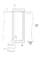
- FIG. 2 is a bottom view of the head 21.
- an ejection surface 210 that ejects ink droplets is provided below the head 21.
- the discharge surface 210 covers the entire width of the transparent substrate 9 in the main scanning direction.
- a plurality of nozzles 211 are regularly arranged on the ejection surface 210. The plurality of nozzles 211 are arranged so that the positions in the main scanning direction are different from each other.
- ink droplets are ejected from the plurality of nozzles 211 of each head 21 toward the printing surface of the transparent substrate 9. That is, ink droplets of cyan, magenta, yellow, and black, which are process colors, are ejected from the plurality of nozzles 211 of each head 21.
- the four heads 21 print single color images of cyan, magenta, yellow, and black on the printing surface of the transparent substrate 9.
- a multicolor image is formed on the printing surface of the transparent substrate 9 by superimposing these four single-color images.
- the multicolor image printed by the first printing unit 20 is referred to as a “process color image”.
- the first drying unit 30 is arranged on the downstream side of the transport path from the first printing unit 20.
- the first drying unit 30 dries the process color ink ejected from the four heads 21 of the first printing unit 20.
- the process color ink is fixed on the printing surface of the transparent substrate 9.
- the first drying unit 30 blows hot air toward the transparent substrate 9 to vaporize the solvent in the ink attached to the transparent substrate 9, thereby drying the ink.
- the 1st drying part 30 may dry or harden ink by other methods, such as light irradiation.
- the second printing unit 40 is disposed downstream of the first drying unit 30 in the conveyance path.
- the second printing unit 40 is a processing unit that discharges non-process color inks different from the above-described cyan, magenta, yellow, and black onto the transparent substrate 9 conveyed by the conveyance mechanism 10.
- the second printing unit 40 of this embodiment has one head 41 that ejects white ink droplets that are non-process colors.
- the head 41 is fixed to the housing (not shown) of the inkjet printing apparatus 1.
- the head 41 of the second printing unit 40 also has a plurality of nozzles, similar to the head 21 of the first printing unit 20 described above.
- the head 41 ejects white ink droplets from a plurality of nozzles toward the printing surface of the transparent substrate 9. Thereby, a white monochrome image is printed on the printing surface of the transparent substrate 9.
- the white monochrome image printed by the second printing unit 40 is referred to as a “non-process color image”.
- the second drying unit 50 is disposed downstream of the second printing unit 40 in the transport path.
- the second drying unit 50 dries the non-process color ink ejected from the head 41 of the second printing unit 40. Thereby, the non-process color ink is fixed on the printing surface of the transparent substrate 9.
- the second drying unit 50 blows a gas heated toward the transparent substrate 9 to evaporate the solvent in the ink attached to the transparent substrate 9, thereby drying the ink.
- the 2nd drying part 50 may dry or harden ink by other methods, such as light irradiation.
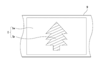
- FIG. 3 is a diagram conceptually showing the relationship between the transparent substrate 9, the process color image Ip, and the non-process color image Iw.
- FIG. 4 is a view of the transparent substrate 9 after printing as viewed from the non-printing surface side (from the direction of arrow A in FIG. 3).
- the process color image Ip is first printed on the printing surface of the transparent substrate 9, and then the non-process color image Iw is printed. Therefore, as shown in FIG. 3, at least a part of the process color image Ip is covered with the non-process color image Iw.
- a printed image I is formed on the printing surface of the transparent substrate 9 by the process color image Ip and the non-process color image Iw.
- the image acquisition unit 60 is disposed downstream of the second drying unit 50 in the conveyance path.
- the image acquisition unit 60 captures the print image I at a predetermined inspection position P on the transport path of the transparent substrate 9.
- the image acquisition unit 60 includes a first light irradiation unit 61, a second light irradiation unit 62, and a photographing unit 63.
- the first light irradiation unit 61 is disposed on one side (printing surface side) of the transparent substrate 9.
- photography part 63 are arrange
- the control unit 70 is means for controlling the operation of each unit in the inkjet printing apparatus 1.
- the control unit 70 of this embodiment is configured by a computer having a processor 71 such as a CPU, a memory 72 such as a RAM, and a storage unit 73 such as a hard disk drive.
- the control unit 70 includes the transport mechanism 10, the four heads 21 of the first printing unit 20, the first drying unit 30, the head 41 of the second printing unit 40, and the second.
- the drying unit 50, the first light irradiation unit 61, the second light irradiation unit 62, and the photographing unit 63 are connected to be communicable with each other.
- the control unit 70 temporarily reads the computer program CP stored in the storage unit 73 into the memory 72, and the processor 71 performs arithmetic processing based on the computer program CP, thereby controlling the operation of each unit described above. Thereby, the printing process in the inkjet printing apparatus 1 and the inspection process described later proceed.
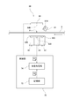
- FIG. 5 is a diagram illustrating the configuration of the image acquisition unit 60.
- the image acquisition unit 60 of the present embodiment includes the first light irradiation unit 61, the second light irradiation unit 62, and the imaging unit 63.
- the first light irradiation unit 61 is located on one side (printing surface side) of the transparent substrate 9 at the inspection position P.
- the first light irradiation unit 61 includes a plurality of light sources 610 arranged in the main scanning direction.
- the light source 610 for example, an LED (Light Emitting Diode, light emitting diode) is used.
- each light source 610 of the first light irradiation unit 61 emits light. Thereby, light is irradiated from the first light irradiation unit 61 toward the transparent substrate 9.
- the light emitted from the first light irradiation unit 61 is preferably white light.
- the second light irradiation unit 62 is located on the other side (non-printing surface side) of the transparent substrate 9 at the inspection position P.
- the second light irradiation unit 62 is provided on the upstream side and the downstream side of the imaging unit 63.
- the installation location of the second light irradiation unit 62 may be only one of the upstream side and the downstream side of the imaging unit 63.
- the second light irradiation unit 62 includes a plurality of light sources 620 arranged in the main scanning direction.
- the light source 620 for example, an LED (Light Emitting Diode, light emitting diode) is used.
- each light source 620 of the second light irradiation unit 62 emits light. Thereby, light is irradiated from the second light irradiation unit 62 toward the transparent substrate 9.
- the light emitted from the second light irradiation unit 62 is preferably white light.
- the first light irradiation unit 61 and the second light irradiation unit 62 of the present embodiment can individually change the amount of irradiation light.
- the setting of the amount of light is performed, for example, when the user inputs a desired value to the control unit 70.
- the imaging unit 63 is located on the other side (non-printing surface side) of the transparent substrate 9 at the inspection position P. That is, the first light irradiation unit 61 and the imaging unit 63 are located on the opposite sides of the transparent substrate 9 with the inspection position P interposed therebetween.
- the imaging unit 63 includes a plurality of imaging elements 630 arranged in the main scanning direction.
- a CCD Charge-Coupled Device
- CMOS Complementary MOS
- the imaging unit 63 images the transparent base material 9 passing through the inspection position P by using these imaging elements 630.
- an image of the transparent substrate 9 passing through the inspection position P is acquired as multi-gradation digital data.
- an image obtained by the photographing unit 63 is referred to as a “photographed image D1”.
- the photographed image D1 is output from the photographing unit 63 to the control unit 70.
- the control unit 70 includes an inspection processing unit 74.
- the inspection processing unit 74 is a processing unit for inspecting the quality of the printed image I printed on the transparent substrate 9 based on the captured image D1 acquired from the imaging unit 63.
- the function of the inspection processing unit 74 is realized by the computer as the control unit 70 operating according to the computer program CP described above.
- an inspection apparatus that inspects the printed image I printed on the surface of the transparent substrate 9 is configured by the first light irradiation unit 61, the second light irradiation unit 62, the imaging unit 63, and the inspection processing unit 74. Is done.
- a normal image D2 is stored in advance.
- the normal image D2 is an image showing a state in which the transparent substrate 9 is normally printed.
- the normal image D2 is generated in the control unit 70 based on the print data.
- the inspection processing unit 74 acquires the captured image D1 from the imaging unit 63 and reads the normal image D2 from the storage unit 73. Then, the captured image D1 and the normal image D2 are compared. As a result, a portion where the difference between the captured image D1 and the normal image D2 is larger than a preset threshold is detected as a defect.
- the types of defects include chipping of the printed image I due to clogging of some nozzles, misalignment of the printed image I on the printing surface of the transparent substrate 9, contamination due to unnecessary dripping of ink from the nozzle, transparent substrate 9 And the like, and the like. Whether characters or codes included in the print image I can be normally identified may be set as one of the inspection items.
- the normal image D2 is generated based on the print data, but is not limited thereto.
- the normal image D2 may be generated from an average image of the plurality of captured images D1. In this case, it is necessary to confirm that the same defect does not occur in the same location, but compared with the case where it is generated based on the print data, the trouble of color conversion and resolution conversion is suppressed, and errors associated with these processes. Can be reduced.
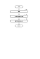
- the image acquisition unit 60 images the transparent substrate 9 that passes through the inspection position P (step S1). Specifically, the imaging unit 63 images the transparent base material 9 at the inspection position P while irradiating light from the first light irradiation unit 61 and the second light irradiation unit 62 described above toward the transparent base material 9. . Thereby, the captured image D1 of the transparent base material 9 at the inspection position P is obtained.
- the first light irradiation unit 61 irradiates light from one side of the transparent substrate 9, and the light enters the imaging unit 63 located on the other side of the transparent substrate 9. That is, the imaging unit 63 receives light irradiated from behind the transparent base material 9. Thereby, it is suppressed that the shadow of the print image I itself is generated in the vicinity of the print image I by the irradiation light from the second light irradiation unit 62. Therefore, the photographing unit 63 can obtain a clear photographed image D1 with a shadow suppressed. The obtained photographed image D1 is output from the photographing unit 63 to the control unit 70.
- the inspection processing unit 74 in the control unit 70 compares the captured image D1 with the normal image D2 read from the storage unit 73. Then, it is determined whether or not there is a defective portion having a large difference from the normal image D2 in the captured image D1 (step S2). Thereby, the quality of the printed image I formed on the printing surface of the transparent substrate 9 is inspected. Specifically, it is determined for each pixel whether the difference between the pixel values of the captured image D1 and the normal image D2 exceeds a preset threshold value, and a pixel that exceeds the threshold value is determined as a defective portion.
- control unit 70 outputs the inspection result by the inspection processing unit 74 (step S3).
- the inspection result is displayed on a display connected to the control unit 70.
- the user of the inkjet printing apparatus 1 can recognize the defect included in the printed image I by confirming the inspection result displayed on the display.
- the control unit 70 does not necessarily display the inspection result.
- the control unit 70 may sequentially accumulate inspection results in a specific storage area in the storage unit 73.
- step S ⁇ b> 1 of the present embodiment the captured image D ⁇ b> 1 in which the generation of the shadow of the printed image I itself is suppressed is acquired by irradiating light from the first light irradiation unit 61. Therefore, in step S2 of the present embodiment, defects in the printed image I can be accurately inspected based on the obtained captured image D1.
- step S1 of the present embodiment not only the first light irradiation unit 61 located on one side of the transparent base material 9 but also the second light irradiation unit 62 located on the other side of the transparent base material 9 Irradiate.
- the photographing unit 63 can photograph the entire print image I more clearly. Therefore, in step S2 of the present embodiment, the defect in the printed image I can be inspected more accurately based on the obtained captured image D1.
- first light irradiation unit 61 and the second light irradiation unit 62 of the present embodiment can individually change the amount of irradiation light. For this reason, each light quantity and the balance of the light quantity of the 1st light irradiation part 61 and the 2nd light irradiation part 62 can be adjusted arbitrarily. Thereby, it is possible to prevent problems such as so-called lens flare from occurring in the captured image D1 due to an inappropriate amount of light. In particular, when the area ratio of the non-process color image Iw is small, lens flare is likely to occur due to the irradiation light from the first light irradiation unit 61.
- control unit 70 may automatically reduce the light amount of the first light irradiation unit 61 as the area ratio of the non-process color image Iw in the print image I is smaller. Note that only one of the first light irradiation unit 61 and the second light irradiation unit 62 may change the light amount.
- FIG. 7 is a diagram illustrating a configuration of the image acquisition unit 60 according to the second embodiment.
- the image acquisition unit 60 of the present embodiment includes a first light irradiation unit 61, a second light irradiation unit 62, a photographing unit 63, and a background plate 64.
- the background plate 64 is located on one side (printing surface side) of the transparent substrate 9 at the inspection position P.
- the background plate 64 has a background surface 640 that extends parallel to the printing surface of the transparent substrate 9 and faces the printing surface.
- the background surface 640 covers the entire width of the transparent substrate 9 in the main scanning direction.
- the color of the background surface 640 of the background plate 64 includes the color of ink ejected from the head 21 of the first printing unit 20 (process color) and the color of ink ejected from the head 41 of the second printing unit 40 (non-process). Color) is different from any of the above.
- the color of the background plate 64 is gray.
- the first light irradiation unit 61 is located on one side (printing surface side) of the transparent substrate 9. In the first light irradiation unit 61 of the present embodiment, the light irradiation direction is directed to the background plate 64, not the transparent substrate 9.
- the first light irradiation unit 61 includes a plurality of light sources 610 arranged in the main scanning direction.
- the light source 610 for example, an LED (Light Emitting Diode, light emitting diode) is used.
- each light source 610 of the first light irradiation unit 61 emits light. Thereby, light is irradiated from the first light irradiation unit 61 toward the background plate 64.
- the light emitted from the first light irradiation unit 61 is preferably white light.
- the second light irradiation unit 62, the imaging unit 63, and the inspection processing unit 74 are the same as those in the first embodiment described above, and thus redundant description is omitted.
- the first light irradiation unit 61, the second light irradiation unit 62, the photographing unit 63, the background plate 64, and the inspection processing unit 74 inspect the printed image I printed on the surface of the transparent substrate 9.
- An inspection device is configured.
- step S ⁇ b> 1 shooting is performed in a state where the background plate 64 is disposed on one side of the transparent substrate 9.
- the first light irradiation unit 61 irradiates light toward the background plate 64, not the transparent substrate 9.
- the light reflected by the background surface 640 of the background plate 64 passes through the transparent substrate 9 and enters the photographing unit 63. In this way, by irradiating the background plate 64 with light, generation of shadows on the background plate 64 is suppressed.
- step S1 the captured image D1 in which the generation of the shadow of the printed image I itself is suppressed can be acquired by the light irradiated from the first light irradiation unit 61 and reflected by the background plate 64. Therefore, in step S2 of the present embodiment, defects in the printed image I can be accurately inspected based on the obtained captured image D1.
- the captured image D1 acquired in step S1 includes a portion of the background surface 640 of the background plate 64 and a portion of the print image I located in front of the portion.
- the color of the background plate 64 includes the color of ink ejected from the head 21 of the first printing unit 20 (process color) and the color of ink ejected from the head 41 of the second printing unit 40 (non-process). Color), which is a different color.
- the process color image Ip and the non-process color image Iw and the background surface 640 appear clearly distinguishable. Therefore, it is possible to accurately inspect the print image I based on the captured image D1.
- the color of the background surface 640 of the background plate 64 may be a color corresponding to a multi-order color including two or more color components of a plurality of process colors and non-process colors. preferable.
- the background color when the background color is gray, it is preferable that the background color be gray corresponding to a multi-order color including cyan, magenta, and yellow color components, rather than gray corresponding to low density black. This is because the multi-order color is less likely to match the color used in the printed image than the single color.
- FIG. 8 is a flowchart showing an example of a background color determination method.
- a plurality of candidate colors that are candidates for the background color are prepared.
- Each candidate color is a multi-order color including two or more color components of a plurality of process colors and non-process colors.
- a plurality of process colors, non-process colors, and a plurality of candidate colors are printed on the transparent substrate 9 (step S11).
- the printed process color, non-process color, and a plurality of candidate colors are photographed by the photographing unit 63 (step S12).
- the captured image acquired by the imaging unit 63 is not CMYK but data defined by RGB. That is, the color in the captured image is represented by a combination of R (red), G (green), and B (blue) values.
- the RGB values of a plurality of process colors and non-process colors are compared with the RGB values of each candidate color (step S13). Then, a candidate color having the largest difference in RGB values for a plurality of process colors and non-process colors is determined as a background color (step S14).
- the background surface 640 of the background plate 64 and the print image I can be more clearly distinguished in the captured image D1. Therefore, it is possible to accurately inspect the print image I based on the captured image D1.
- FIG. 9 is a diagram illustrating a configuration of the image acquisition unit 60 according to the third embodiment.
- the image acquisition unit 60 of the present embodiment is different from the second embodiment in that a projection unit 65 is provided instead of the first light irradiation unit 61. That is, the image acquisition unit 60 of the present embodiment includes a second light irradiation unit 62, an imaging unit 63, a background plate 64, and a projection unit 65.
- the background surface 640 of the background plate 64 is white.
- the projection unit 65 is located on one side (printing surface side) of the transparent substrate 9.
- the projection unit 65 is directed to the background surface 640 of the background plate 64.
- the projection unit 65 has a plurality of rows of light sources 650 arranged in the main scanning direction.
- the light sources 650 in each column emit light in different colors.
- an LED Light Emitting Diode, light emitting diode
- the projection unit 65 causes the light sources 650 in an arbitrary column to emit light in response to a command from the control unit 70. Thereby, light of a plurality of colors is selectively irradiated from the projection unit 65 toward the background surface 640 of the background plate 64.
- the second light irradiation unit 62, the imaging unit 63, and the inspection processing unit 74 are the same as those in the first embodiment and the second embodiment described above, and thus redundant description is omitted.
- the inspection apparatus that inspects the printed image I printed on the surface of the transparent substrate 9 by the second light irradiation unit 62, the imaging unit 63, the background plate 64, the projection unit 65, and the inspection processing unit 74. Composed.
- the print image I is inspected by the same procedure as the flowchart of FIG.
- step S ⁇ b> 1 shooting is performed in a state where the background plate 64 is disposed on one side of the transparent substrate 9.
- the projection unit 65 emits light of a predetermined color toward the background plate 64.
- the light reflected by the background surface 640 of the background plate 64 passes through the transparent substrate 9 and enters the photographing unit 63. In this way, by irradiating the background plate 64 with light, generation of shadows on the background plate 64 is suppressed.
- step S1 the photographed image D1 in which the shadow of the print image I itself is suppressed can be acquired by the light emitted from the projection unit 65 and reflected by the background plate 64. Therefore, in step S2 of the present embodiment, defects in the printed image I can be accurately inspected based on the obtained captured image D1.
- the captured image D1 acquired in step S1 includes a portion of the background surface 640 of the background plate 64 and a portion of the print image I located in front of the portion.
- the color of light emitted from the projection unit 65 to the background plate 64 is, for example, the color of ink ejected from the head 21 of the first printing unit 20 (process color) and the head 41 of the second printing unit 40.
- the color of the ink ejected from the ink (non-process color) is different from each other. For this reason, in the acquired captured image D1, the process color image Ip and the non-process color image Iw and the background surface 640 appear clearly distinguishable. Therefore, it is possible to accurately inspect the print image I based on the captured image D1.
- the control unit 70 switches the color of light emitted from the projection unit 65 according to the print image I. Specifically, among the light colors that can be emitted from the projection unit 65, the projection unit 65 emits light of a color having the largest RGB value difference with respect to the color included in the print image I. For example, in the case of a printed image I having a high percentage of green, such as a label for a green tea beverage, a red light is emitted in contrast thereto. Further, for example, in the case of a printed image I having a high blue ratio, such as a sports drink label, a contrasting orange color is emitted.
- the print image I is a test chart printed for each color of cyan, magenta, yellow, black, and white for nozzle inspection
- the color of light emitted from the projection unit 65 for each color of the test chart May be changed.
- the print image I and the background surface 640 can be more clearly distinguished. Therefore, the print image I can be inspected more accurately based on the captured image D1.
- the second light irradiation unit 62 may be omitted.
- the first light irradiation unit 61 may be omitted.
- the second light irradiation unit 62 may be omitted.
- the second light irradiation unit 62 may be omitted.
- the light emitted from the first light irradiation unit 61 may be light other than white light.
- the color of light emitted from the first light irradiation unit 61 is set to the color of the ink (process color) discharged from the head 21 of the first printing unit 20 and the head 41 of the second printing unit 40.
- the ink color (non-process color) may be different from any other color.
- the color of light emitted from the first light irradiation unit 61 may be switched.
- the first printing unit 20 has the four heads 21.
- the number of the heads 21 included in the first printing unit 20 may be 1 to 3, or 5 or more.
- a head 21 that ejects ink of special colors such as purple violet and green may be provided.
- the inkjet printing apparatus of the present invention may perform printing on each transparent substrate while sequentially transporting a plurality of transparent substrates in the sub-scanning direction.
Landscapes
- Engineering & Computer Science (AREA)
- Physics & Mathematics (AREA)
- Spectroscopy & Molecular Physics (AREA)
- General Physics & Mathematics (AREA)
- Multimedia (AREA)
- Signal Processing (AREA)
- Quality & Reliability (AREA)
- Textile Engineering (AREA)
- General Engineering & Computer Science (AREA)
- Theoretical Computer Science (AREA)
- Ink Jet (AREA)
- Investigating Materials By The Use Of Optical Means Adapted For Particular Applications (AREA)
Abstract
透明基材の表面に印刷された印刷画像を、精度よく検査できる検査装置、インクジェット印刷装置、および検査方法を提供する。第1光照射部(61)は、透明基材(9)の一方側から透明基材(9)へ向けて光を照射する。撮影部(63)は、透明基材(9)の他方側から透明基材(9)を撮影する。このように、第1光照射部(61)と撮影部(63)とを、透明基材(9)に対して互いに反対側に配置する。これにより、印刷画像自体の影が撮影画像(D1)中に生じることを抑制できる。したがって、得られた撮影画像(D1)に基づいて、印刷画像を精度よく検査できる。
Description
本発明は、透明基材の表面に印刷された印刷画像を検査する検査装置、当該検査装置を含むインクジェット印刷装置、および、透明基材の表面に印刷された印刷画像を検査する検査方法に関する。
従来、透明基材を搬送しつつ、ヘッドからインクを吐出することにより、透明基材に画像を印刷するインクジェット印刷装置が知られている。この種のインクジェット印刷装置は、例えば、飲料用ペットボトルのラベルや、軟包装材の製造工程において使用される。透明基材に対して印刷を行う従来のインクジェット印刷装置については、例えば、特許文献1,2に記載されている。
ラベルや軟包装材の製造工程では、透明基材への印刷後に、印刷画像に欠陥が無いかどうかを検査することが求められる。欠陥の種類としては、例えば、ノズルの詰まり等による印刷画像の欠け、透明基材に対する印刷画像の位置ずれ、ノズルからのインクの不要な滴下による汚れ、透明基材に対する異物の付着、等を挙げることができる。
透明基材上の印刷画像を検査するときには、従来、基材の一方側に背景板を配置した状態で、基材の他方側から光を照射しつつ基材を撮影していた。そして、撮影により得られる画像と正常画像とを比較することにより、欠陥を検出していた。しかしながら、この方法では、光の照射によって、背景板に印刷画像自体の影が発生する。このため、この影を誤検出しないように、検査の感度を抑える必要がある。それゆえ、透明基材の表面に印刷された印刷画像を精度よく検査することが困難であった。
また、従来、背景板の色は、ホワイトとされていた。しかしながら、透明基材への印刷においては、シアン、マゼンタ、イエロー、およびブラックの、いわゆるプロセスカラーのインクや、パープル・バイオレット、およびグリーンなどのいわゆる特色インクだけではなく、ホワイトのインクも使用される場合がある。従来の検査では、ホワイトの背景板と、ホワイトのインクにより形成される画像とを、精度よく区別することが困難であった。それゆえ、透明基材の表面に印刷された印刷画像を精度よく検査することが困難であった。
本発明は、これらの事情に鑑みなされたものであり、透明基材の表面に印刷された印刷画像を、精度よく検査できる検査装置、インクジェット印刷装置、および検査方法を提供することを目的とする。
本願の第1発明は、透明基材の表面に印刷された印刷画像を検査する検査装置であって、透明基材の一方側から透明基材へ向けて光を照射する第1光照射部と、透明基材の他方側から透明基材を撮影する撮影部と、前記撮影部により得られた撮影画像に基づいて、前記印刷画像の良否を検査する検査処理部と、を備える。
本願の第2発明は、第1発明の検査装置であって、前記印刷画像は、複数のプロセスカラーのインクにより形成されるプロセスカラー画像と、前記複数のプロセスカラーとは異なる非プロセスカラーのインクにより形成され、前記プロセスカラー画像の前記一方側を覆う非プロセスカラー画像と、を含み、透明基材の前記他方側から透明基材へ向けて光を照射する第2光照射部をさらに備える。
本願の第3発明は、第2発明の検査装置であって、前記第1光照射部および前記第2光照射部の少なくとも一方は、光量を変更可能である。
本願の第4発明は、第3発明の検査装置であって、前記非プロセスカラー画像の面積率が小さいほど、前記第1光照射部の光量を低下させる制御部をさらに備える。
本願の第5発明は、第2発明から第4発明までのいずれか1発明の検査装置であって、前記複数のプロセスカラーは、シアン、マゼンタ、イエロー、およびブラックを含み、前記非プロセスカラーは、ホワイトである。
本願の第6発明は、透明基材の表面に印刷された印刷画像を検査する検査装置であって、前記印刷画像は、複数のプロセスカラーのインクにより形成されるプロセスカラー画像と、前記複数のプロセスカラーとは異なる非プロセスカラーのインクにより形成され、前記プロセスカラー画像を覆う非プロセスカラー画像と、を含み、前記検査装置は、透明基材の一方側に配置された背景板と、透明基材の他方側から透明基材を撮影する撮影部と、前記撮影部により得られた撮影画像に基づいて、前記印刷画像の良否を検査する検査処理部と、を備え、前記背景板の色は、前記複数のプロセスカラーおよび前記非プロセスカラーのいずれとも異なる色である。
本願の第7発明は、第6発明の検査装置であって、前記背景板の色は、前記複数のプロセスカラーおよび前記非プロセスカラーのうちの2つ以上の色成分を含む多次色である。
本願の第8発明は、第6発明または第7発明の検査装置であって、前記背景板の透明基材側の面へ向けて光を照射する光照射部をさらに備える。
本願の第9発明は、第6発明から第8発明までのいずれか1発明の検査装置であって、前記複数のプロセスカラーは、シアン、マゼンタ、イエロー、およびブラックを含み、前記非プロセスカラーは、ホワイトである。
本願の第10発明は、透明基材の表面に印刷された印刷画像を検査する検査装置であって、透明基材の一方側に配置された背景板と、前記背景板の透明基材側の面に複数色の投影光を切り替えつつ照射する投影部と、透明基材の他方側から透明基材を撮影する撮影部と、前記撮影部により得られた撮影画像に基づいて、前記印刷画像の良否を検査する検査処理部と、を備える。
本願の第11発明は、第1発明から第10発明までのいずれか1発明の検査装置を含むインクジェット印刷装置であって、透明基材を所定の搬送経路に沿って搬送する搬送機構と、前記搬送機構により搬送される透明基材の表面に、インクジェット方式で印刷を行う印刷部と、を備え、前記光照射部および前記撮影部は、前記印刷部よりも、前記搬送経路の下流側に位置する。
本願の第12発明は、透明基材の表面に印刷された印刷画像を検査する検査方法であって、a)透明基材の一方側から透明基材へ向けて光を照射しつつ、透明基材の他方側から透明基材を撮影する工程と、b)前記工程a)により得られた撮影画像に基づいて、前記印刷画像の良否を検査する工程と、を有する。
本願の第13発明は、透明基材の表面に印刷された印刷画像を検査する検査方法であって、前記印刷画像は、複数のプロセスカラーのインクにより形成されるプロセスカラー画像と、前記複数のプロセスカラーとは異なる非プロセスカラーのインクにより形成され、前記プロセスカラー画像を覆う非プロセスカラー画像と、を含み、前記検査方法は、a)透明基材の一方側に背景板が配置された状態で、透明基材の他方側から透明基材を撮影する工程と、b)前記工程a)により得られた撮影画像に基づいて、前記印刷画像の良否を検査する工程と、を有し、前記背景板の色は、前記複数のプロセスカラーおよび前記非プロセスカラーのいずれとも異なる色である。
本願の第14発明は、透明基材の表面に印刷された印刷画像を検査する検査方法であって、a)透明基材の一方側に背景板が配置された状態で、透明基材の他方側から透明基材を撮影する工程と、b)前記工程a)により得られた撮影画像に基づいて、前記印刷画像の良否を検査する工程と、を有し、前記工程a)では、前記背景板の透明基材側の面に、前記印刷画像に応じて異なる色の投影光を照射する。
本願の第1発明~第5発明によれば、第1光照射部と撮影部とを、透明基材に対して互いに反対側に配置する。これにより、印刷画像自体の影が撮影画像中に生じることを抑制できる。したがって、得られた撮影画像に基づいて、印刷画像を精度よく検査できる。
特に、本願の第2発明によれば、非プロセスカラー画像に覆われるプロセスカラー画像を、第2光照射部からの照射光によって、良好に撮影できる。
本願の第6発明~第9発明によれば、撮影画像において、プロセスカラー画像および非プロセスカラー画像と、背景板とが、明瞭に区別可能に現れる。したがって、得られた撮影画像に基づいて、印刷画像を精度よく検査できる。
本願の第10発明によれば、印刷画像に応じて、背景板に照射される投影光の色を切り替えることができる。これにより、撮影画像中に印刷画像が良好に現れる。したがって、得られた撮影画像に基づいて、印刷画像を精度よく検査できる。
本願の第11発明によれば、透明基材に印刷を行うインクジェット印刷装置において、印刷後の検査を精度よく行うことができる。
本願の第12発明によれば、透明基材の一方側から光を照射しつつ、透明基材の他方側から透明基材を撮影する。これにより、印刷画像自体の影が撮影画像中に生じることを抑制できる。したがって、得られた撮影画像に基づいて、印刷画像を精度よく検査できる。
本願の第13発明によれば、撮影画像において、プロセスカラー画像および非プロセスカラー画像と、背景板とが、明瞭に区別可能に現れる。したがって、得られた撮影画像に基づいて、印刷画像を精度よく検査できる。
本願の第14発明によれば、背景板の透明基材側の面に、印刷画像に応じて異なる色の投影光を照射する。これにより、印刷画像が撮影画像中に良好に現れる。したがって、得られた撮影画像に基づいて、印刷画像を精度よく検査できる。
以下、本発明の実施形態について、図面を参照しつつ説明する。なお、以下では、透明基材の搬送方向に直交し、かつ、透明基材の表面に沿う方向を「主走査方向」と称する。また、透明基材の搬送方向を「副走査方向」と称する。
<1.第1実施形態>
<1-1.インクジェット印刷装置の構成>
図1は、本発明の第1実施形態に係るインクジェット印刷装置1の構成を示す図である。このインクジェット印刷装置1は、長尺帯状の透明基材9を搬送しつつ、透明基材9の表面に、インクジェット方式で多色画像を印刷する装置である。透明基材9には、例えば、無色透明の樹脂フィルムが用いられる。印刷後の透明基材9は、切断されて、例えば、飲料用ペットボトルのラベルとなる。
<1-1.インクジェット印刷装置の構成>
図1は、本発明の第1実施形態に係るインクジェット印刷装置1の構成を示す図である。このインクジェット印刷装置1は、長尺帯状の透明基材9を搬送しつつ、透明基材9の表面に、インクジェット方式で多色画像を印刷する装置である。透明基材9には、例えば、無色透明の樹脂フィルムが用いられる。印刷後の透明基材9は、切断されて、例えば、飲料用ペットボトルのラベルとなる。
図1に示すように、インクジェット印刷装置1は、搬送機構10、第1印刷部20、第1乾燥部30、第2印刷部40、第2乾燥部50、画像取得部60、および制御部70を備えている。
搬送機構10は、透明基材9をその長手方向である副走査方向に搬送する機構である。本実施形態の搬送機構10は、巻き出し部11、複数の搬送ローラ12、および巻き取り部13を有する。透明基材9は、巻き出し部11から繰り出され、複数の搬送ローラ12により構成される搬送経路に沿って搬送される。各搬送ローラ12は、水平軸を中心として回転することによって、透明基材9を搬送経路の下流側へ案内する。また、搬送後の透明基材9は、巻き取り部13へ回収される。
図1に示すように、透明基材9は、第1印刷部20および第2印刷部40の下方位置においては、略水平に移動する。このとき、透明基材9の印刷面は、上方に向けられている。また、透明基材9は、張力がかけられた状態で、複数の搬送ローラ12に掛け渡されている。これにより、搬送中における透明基材9の弛みや皺が抑制される。
第1印刷部20は、搬送機構10により搬送される透明基材9に対して、いわゆるプロセスカラーのインクを吐出する処理部である。本実施形態の第1印刷部20は、4つのヘッド21を有する。これらのヘッド21は、プロセスカラーであるシアン(Cyan)、マゼンタ(Magenta)、イエロー(Yellow)、およびブラック(Black)の各色のインク滴を、透明基材9の印刷面に、それぞれ吐出する。各ヘッド21は、インクジェット印刷装置1のハウジング(図示省略)に対して、固定されている。
図2は、ヘッド21の下面図である。図2に示すように、ヘッド21の下部には、インク滴を吐出する吐出面210が設けられている。吐出面210は、透明基材9の主走査方向の全幅を覆っている。また、図2中に拡大して示したように、吐出面210には、複数のノズル211が規則的に配列されている。複数のノズル211は、互いに主走査方向の位置が異なるように配列されている。
印刷時には、各ヘッド21の複数のノズル211から、透明基材9の印刷面へ向けて、インク滴が吐出される。すなわち、プロセスカラーであるシアン、マゼンタ、イエロー、およびブラックの各色のインク滴が、各ヘッド21の複数のノズル211から吐出される。その結果、4つのヘッド21は、透明基材9の印刷面に、シアン、マゼンタ、イエロー、およびブラックの各色の単色画像を印刷する。そして、これらの4つの単色画像の重ね合わせによって、透明基材9の印刷面に多色画像が形成される。以下では、第1印刷部20により印刷される多色画像を、「プロセスカラー画像」と称する。
第1乾燥部30は、第1印刷部20よりも搬送経路の下流側に配置されている。第1乾燥部30は、第1印刷部20の4つのヘッド21から吐出されたプロセスカラーのインクを乾燥させる。これにより、透明基材9の印刷面に、プロセスカラーのインクを定着させる。第1乾燥部30は、例えば、透明基材9へ向けて熱風を吹き付けて、透明基材9に付着したインク中の溶媒を気化させることにより、インクを乾燥させる。ただし、第1乾燥部30は、光照射等の他の方法で、インクを乾燥または硬化させるものであってもよい。
第2印刷部40は、第1乾燥部30よりも搬送経路の下流側に配置されている。第2印刷部40は、搬送機構10により搬送される透明基材9に対して、上述したシアン、マゼンタ、イエロー、およびブラックとは異なる非プロセスカラーのインクを吐出する処理部である。本実施形態の第2印刷部40は、非プロセスカラーであるホワイト(White)のインク滴を吐出する1つのヘッド41を有する。ヘッド41は、インクジェット印刷装置1のハウジング(図示省略)に対して、固定されている。
第2印刷部40のヘッド41も、上述した第1印刷部20のヘッド21と同様に、複数のノズルを有する。ヘッド41は、複数のノズルから透明基材9の印刷面に向けて、ホワイトのインク滴を吐出する。これにより、透明基材9の印刷面に、ホワイトの単色画像が印刷される。以下では、第2印刷部40により印刷されるホワイトの単色画像を「非プロセスカラー画像」と称する。
第2乾燥部50は、第2印刷部40よりも搬送経路の下流側に配置されている。第2乾燥部50は、第2印刷部40のヘッド41から吐出された非プロセスカラーのインクを乾燥させる。これにより、透明基材9の印刷面に、非プロセスカラーのインクを定着させる。第2乾燥部50は、例えば、透明基材9へ向けて加熱された気体を吹き付けて、透明基材9に付着したインク中の溶媒を気化させることにより、インクを乾燥させる。ただし、第2乾燥部50は、光照射等の他の方法で、インクを乾燥または硬化させるものであってもよい。
図3は、透明基材9、プロセスカラー画像Ip、および非プロセスカラー画像Iwの関係を、概念的に示した図である。図4は、印刷後の透明基材9を、非印刷面側から(図3中の矢印Aの方向から)見た図である。上述の通り、本実施形態のインクジェット印刷装置1では、透明基材9の印刷面に、まず、プロセスカラー画像Ipが印刷され、その後に、非プロセスカラー画像Iwが印刷される。したがって、図3に示すように、プロセスカラー画像Ipの少なくとも一部は、非プロセスカラー画像Iwに覆われる。これらのプロセスカラー画像Ipおよび非プロセスカラー画像Iwによって、透明基材9の印刷面に印刷画像Iが形成される。
図1を再び参照する。画像取得部60は、第2乾燥部50よりも搬送経路の下流側に配置されている。画像取得部60は、透明基材9の搬送経路上の所定の検査位置Pにおいて、印刷画像Iを撮影する。図1に示すように、画像取得部60は、第1光照射部61、第2光照射部62、および撮影部63を有する。第1光照射部61は、透明基材9の一方側(印刷面側)に配置されている。第2光照射部62および撮影部63は、透明基材9の他方側(非印刷面側)に配置されている。
画像取得部60の詳細については、後述する。
制御部70は、インクジェット印刷装置1内の各部を動作制御するための手段である。本実施形態の制御部70は、CPU等のプロセッサ71、RAM等のメモリ72、およびハードディスクドライブ等の記憶部73を有するコンピュータにより構成されている。図1中に破線で示したように、制御部70は、上述した搬送機構10、第1印刷部20の4つのヘッド21、第1乾燥部30、第2印刷部40のヘッド41、第2乾燥部50、第1光照射部61、第2光照射部62、および撮影部63と、それぞれ通信可能に接続されている。制御部70は、記憶部73に記憶されたコンピュータプログラムCPをメモリ72に一時的に読み出し、当該コンピュータプログラムCPに基づいて、プロセッサ71が演算処理を行うことにより、上記の各部を動作制御する。これにより、インクジェット印刷装置1における印刷処理や、後述する検査処理が進行する。
<1-2.画像取得部について>
続いて、画像取得部60の詳細について説明する。図5は、画像取得部60の構成を示した図である。上述のとおり、本実施形態の画像取得部60は、第1光照射部61、第2光照射部62、および撮影部63を有する。
続いて、画像取得部60の詳細について説明する。図5は、画像取得部60の構成を示した図である。上述のとおり、本実施形態の画像取得部60は、第1光照射部61、第2光照射部62、および撮影部63を有する。
第1光照射部61は、検査位置Pにおける透明基材9の一方側(印刷面側)に位置する。第1光照射部61は、主走査方向に配列された複数の光源610を有する。光源610には、例えば、LED(Light Emitting Diode,発光ダイオード)が用いられる。制御部70からの指令により、第1光照射部61に駆動電流が供給されると、第1光照射部61の各光源610が発光する。これにより、第1光照射部61から透明基材9へ向けて、光が照射される。第1光照射部61から照射される光は、白色光であることが好ましい。
第2光照射部62は、検査位置Pにおける透明基材9の他方側(非印刷面側)に位置する。本実施形態では、撮影部63の上流側と下流側とに、第2光照射部62が設けられている。ただし、第2光照射部62の設置箇所は、撮影部63の上流側および下流側のいずれか一方のみであってもよい。第2光照射部62は、主走査方向に配列された複数の光源620を有する。光源620には、例えば、LED(Light Emitting Diode,発光ダイオード)が用いられる。制御部70からの指令により、第2光照射部62に駆動電流が供給されると、第2光照射部62の各光源620が発光する。これにより、第2光照射部62から透明基材9へ向けて、光が照射される。第2光照射部62から照射される光は、白色光であることが好ましい。
本実施形態の第1光照射部61および第2光照射部62は、照射光の光量を個別に変更可能である。光量の設定は、例えば、制御部70に対してユーザが所望の値を入力することにより、行われる。
撮影部63は、検査位置Pにおける透明基材9の他方側(非印刷面側)に位置する。すなわち、第1光照射部61と撮影部63とは、検査位置Pを挟んで、互いに透明基材9の反対側に位置する。撮影部63は、主走査方向に配列された複数の撮像素子630を有する。撮像素子630には、例えば、CCD(Charge-Coupled Device)やCMOS(Complementary MOS)が用いられる。撮影部63は、これらの撮像素子630により、検査位置Pを通過する透明基材9を撮影する。その結果、検査位置Pを通過する透明基材9の画像が、多階調のデジタルデータとして取得される。以下では、撮影部63により得られる画像を「撮影画像D1」と称する。撮影画像D1は、撮影部63から制御部70へ出力される。
また、図5中に概念的に示したように、制御部70は、検査処理部74を有する。検査処理部74は、撮影部63から取得された撮影画像D1に基づいて、透明基材9に印刷された印刷画像Iの良否を検査するための処理部である。検査処理部74の機能は、制御部70としてのコンピュータが、上述したコンピュータプログラムCPに従って動作することにより、実現される。本実施形態では、第1光照射部61、第2光照射部62、撮影部63、および検査処理部74によって、透明基材9の表面に印刷された印刷画像Iを検査する検査装置が構成される。
制御部70の記憶部73内には、予め正常画像D2が記憶されている。正常画像D2は、透明基材9に正常に印刷がされた状態を示す画像である。正常画像D2は、印刷データに基づいて、制御部70内で生成される。検査処理部74は、撮影部63から撮影画像D1を取得するとともに、記憶部73から正常画像D2を読み出す。そして、撮影画像D1と正常画像D2とを比較する。その結果、撮影画像D1と正常画像D2との差が、予め設定された閾値よりも大きい部分を、欠陥として検出する。
欠陥の種類としては、一部のノズルの詰まり等による印刷画像Iの欠け、透明基材9の印刷面における印刷画像Iの位置ずれ、ノズルからのインクの不要な滴下による汚れ、透明基材9に対する異物の付着、等を挙げることができる。印刷画像Iに含まれる文字やコードが正常に識別できるか否かも、検査項目の1つとして設定されていてもよい。
また、本実施形態では、正常画像D2は、印刷データに基づいて生成されたものを使用しているが、これに限られるものではない。例えば、同じ画像を繰り返し印刷する場合において、正常画像D2は、複数の撮像画像D1の平均画像などから生成してもよい。この場合、同一箇所に同一欠陥が発生していないことを確認する必要はあるが、印刷データに基づいて生成する場合に比べて、色変換や解像度変換の手間を抑制し、これら処理に伴う誤差の軽減を行うことができる。
<1-3.検査手順>
続いて、インクジェット印刷装置1における印刷画像Iの検査手順について、図6のフローチャートを参照しつつ、説明する。インクジェット印刷装置1は、透明基材9への印刷処理を実行する間、図6のステップS1~S3を、繰り返し実行する。
続いて、インクジェット印刷装置1における印刷画像Iの検査手順について、図6のフローチャートを参照しつつ、説明する。インクジェット印刷装置1は、透明基材9への印刷処理を実行する間、図6のステップS1~S3を、繰り返し実行する。
まず、画像取得部60が、検査位置Pを通過する透明基材9を撮影する(ステップS1)。具体的には、上述した第1光照射部61および第2光照射部62から透明基材9へ向けて光を照射しつつ、撮影部63が、検査位置Pの透明基材9を撮影する。これにより、検査位置Pにおける透明基材9の撮影画像D1が得られる。
このとき、第1光照射部61は、透明基材9の一方側から光を照射し、その光が、透明基材9の他方側に位置する撮影部63へ入射する。すなわち、撮影部63は、透明基材9の背後から照射される光を受ける。これにより、第2光照射部62からの照射光によって、印刷画像Iの近傍に、印刷画像I自体の影が生じることが抑制される。したがって、撮影部63は、影を抑えた明瞭な撮影画像D1を得ることができる。得られた撮影画像D1は、撮影部63から制御部70へ出力される。
制御部70に撮影画像D1が入力されると、制御部70内の検査処理部74が、当該撮影画像D1と、記憶部73から読み出した正常画像D2とを比較する。そして、撮影画像D1中に、正常画像D2に対する差が大きい欠陥箇所があるか否かを判断する(ステップS2)。これにより、透明基材9の印刷面に形成された印刷画像Iの良否を検査する。具体的には、撮影画像D1と正常画像D2とで、画素値の差が、予め設定された閾値を超えるか否かを画素毎に判断し、閾値を超えた画素を、欠陥箇所とする。
その後、制御部70は、検査処理部74による検査結果を出力する(ステップS3)。例えば、制御部70に接続されたディスプレイに、検査結果を表示する。インクジェット印刷装置1のユーザは、ディスプレイに表示された検査結果を確認することによって、印刷画像Iに含まれる欠陥を認識することができる。ただし、制御部70は、必ずしも検査結果を表示しなくてもよい。制御部70は、記憶部73内の特定の記憶領域に、検査結果を順次に蓄積してもよい。
以上のように、本実施形態のステップS1では、第1光照射部61から光を照射することにより、印刷画像I自体の影の発生を抑えた撮影画像D1を取得する。したがって、本実施形態のステップS2では、得られた撮影画像D1に基づいて、印刷画像I中の欠陥を精度よく検査できる。
なお、図3のように、プロセスカラー画像Ipの一部分が非プロセスカラー画像Iwに覆われている場合、第1光照射部61からの照射光は、非プロセスカラー画像Iwに遮られて、プロセスカラー画像Ipの当該一部分に十分に照射されない。しかしながら、本実施形態のステップS1では、透明基材9の一方側に位置する第1光照射部61だけではなく、透明基材9の他方側に位置する第2光照射部62からも、光を照射する。これにより、プロセスカラー画像Ipの非プロセスカラー画像Iwに覆われた部分にも、十分に光が照射される。したがって、撮影部63は、印刷画像Iの全体を、より明瞭に撮影することができる。したがって、本実施形態のステップS2では、得られた撮影画像D1に基づいて、印刷画像I中の欠陥を、より精度よく検査できる。
また、本実施形態の第1光照射部61および第2光照射部62は、照射光の光量を個別に変更可能である。このため、第1光照射部61および第2光照射部62の各々の光量および光量のバランスを、任意に調節できる。これにより、不適切な光量によって、撮影画像D1に、いわゆるレンズフレア等の不具合が発生することを防止できる。特に、非プロセスカラー画像Iwの面積率が小さい場合には、第1光照射部61からの照射光によるレンズフレアが発生しやすい。このため、制御部70は、印刷画像Iにおける非プロセスカラー画像Iwの面積率が小さいほど、第1光照射部61の光量を自動的に低下させるようにしてもよい。なお、第1光照射部61および第2光照射部62のうちの一方のみが、光量を変更可能であってもよい。
<2.第2実施形態>
続いて、本発明の第2実施形態について、説明する。図7は、第2実施形態に係る画像取得部60の構成を示した図である。図7に示すように、本実施形態の画像取得部60は、第1光照射部61、第2光照射部62、撮影部63、および背景板64を有する。
続いて、本発明の第2実施形態について、説明する。図7は、第2実施形態に係る画像取得部60の構成を示した図である。図7に示すように、本実施形態の画像取得部60は、第1光照射部61、第2光照射部62、撮影部63、および背景板64を有する。
背景板64は、検査位置Pにおける透明基材9の一方側(印刷面側)に位置する。背景板64は、透明基材9の印刷面に対して平行に広がり、印刷面に対向する背景面640を有する。背景面640は、透明基材9の主走査方向の全幅を覆う。背景板64の背景面640の色は、第1印刷部20のヘッド21から吐出されるインクの色(プロセスカラー)、および第2印刷部40のヘッド41から吐出されるインクの色(非プロセスカラー)の、いずれとも異なる色とされる。例えば、背景板64の色は、グレーとされる。
第1光照射部61は、透明基材9の一方側(印刷面側)に位置する。本実施形態の第1光照射部61は、その光の照射方向が、透明基材9ではなく、背景板64に向けられている。第1光照射部61は、主走査方向に配列された複数の光源610を有する。光源610には、例えば、LED(Light Emitting Diode,発光ダイオード)が用いられる。制御部70からの指令により、第1光照射部61に駆動電流が供給されると、第1光照射部61の各光源610が発光する。これにより、第1光照射部61から背景板64へ向けて、光が照射される。第1光照射部61から照射される光は、白色光であることが好ましい。
第2光照射部62、撮影部63、および検査処理部74については、上記の第1実施形態と同等であるため、重複説明を省略する。本実施形態では、第1光照射部61、第2光照射部62、撮影部63、背景板64、および検査処理部74によって、透明基材9の表面に印刷された印刷画像Iを検査する検査装置が構成される。
この第2実施形態においても、図6のフローチャートと同等の手順により、印刷画像Iの検査が実行される。ただし、ステップS1では、透明基材9の一方側に背景板64が配置された状態で、撮影が行われる。第1光照射部61は、透明基材9ではなく、背景板64へ向けて、光を照射する。そして、背景板64の背景面640で反射された光が、透明基材9を通って、撮影部63へ入射する。このように、背景板64に対して光を照射することにより、背景板64における影の発生が抑制される。
すなわち、本実施形態では、ステップS1において、第1光照射部61から照射されて背景板64で反射される光により、印刷画像I自体の影の発生を抑えた撮影画像D1を取得できる。したがって、本実施形態のステップS2では、得られた撮影画像D1に基づいて、印刷画像I中の欠陥を精度よく検査できる。
ステップS1において取得される撮影画像D1には、背景板64の背景面640の部分と、その手前に位置する印刷画像Iの部分とが、含まれる。上述の通り、背景板64の色は、第1印刷部20のヘッド21から吐出されるインクの色(プロセスカラー)、および第2印刷部40のヘッド41から吐出されるインクの色(非プロセスカラー)の、いずれとも異なる色である。このため、取得される撮影画像D1において、プロセスカラー画像Ipおよび非プロセスカラー画像Iwと、背景面640とが、明瞭に区別可能に現れる。したがって、撮影画像D1に基づいて、印刷画像Iを精度よく検査できる。
背景板64の背景面640の色(以下「背景色」と称する)は、複数のプロセスカラーと非プロセスカラーのうちの2つ以上の色成分を含む多次色に相当する色とすることが好ましい。例えば、背景色をグレーとする場合、低濃度のブラックに相当するグレーとするよりも、シアン、マゼンタ、およびイエローの色成分を含む多次色に相当するグレーとすることが好ましい。これは、単色よりも多次色の方が、印刷画像中に使用される色と一致する可能性が低いからである。
図8は、背景色の決定方法の一例を示すフローチャートである。背景色を決定するときには、まず、背景色の候補となる候補色を複数用意する。各候補色は、複数のプロセスカラーと非プロセスカラーのうちの2つ以上の色成分を含む多次色とする。図8に示すように、まず、透明基材9に、複数のプロセスカラーと、非プロセスカラーと、複数の候補色とを、印刷する(ステップS11)。次に、印刷されたプロセスカラーと、非プロセスカラーと、複数の候補色とを、撮影部63により撮影する(ステップS12)。
ここで、撮影部63により取得される撮影画像は、CMYKではなく、RGBにより定義されたデータとなる。すなわち、撮影画像における色は、R(レッド)、G(グリーン)、およびB(ブルー)の各値の組み合わせによって表される。ステップS12で撮影画像を取得した後、複数のプロセスカラーおよび非プロセスカラーのRGBの値と、各候補色のRGBの値とを、比較する(ステップS13)。そして、複数のプロセスカラーおよび非プロセスカラーに対して、RGBの値の差が最も大きい候補色を、背景色として決定する(ステップS14)。
このようにして決定された背景色を用いれば、背景板64の背景面640と、印刷画像Iとを、撮影画像D1中において、より明瞭に区別できる。したがって、撮影画像D1に基づいて、印刷画像Iを精度よく検査できる。
<3.第3実施形態>
続いて、本発明の第3実施形態について、説明する。図9は、第3実施形態に係る画像取得部60の構成を示した図である。図9に示すように、本実施形態の画像取得部60は、第1光照射部61に代えて、投影部65を有する点が、第2実施形態と異なる。すなわち、本実施形態の画像取得部60は、第2光照射部62、撮影部63、背景板64、および投影部65を有する。本実施形態における背景板64の背景面640の色は、ホワイトとする。
続いて、本発明の第3実施形態について、説明する。図9は、第3実施形態に係る画像取得部60の構成を示した図である。図9に示すように、本実施形態の画像取得部60は、第1光照射部61に代えて、投影部65を有する点が、第2実施形態と異なる。すなわち、本実施形態の画像取得部60は、第2光照射部62、撮影部63、背景板64、および投影部65を有する。本実施形態における背景板64の背景面640の色は、ホワイトとする。
投影部65は、透明基材9の一方側(印刷面側)に位置する。投影部65は、背景板64の背景面640に向けられている。投影部65は、主走査方向に配列された光源650の列を、複数有する。各列の光源650は、異なる色に発光する。光源650には、例えば、LED(Light Emitting Diode,発光ダイオード)が用いられる。投影部65は、制御部70からの指令に応じて、任意の列の光源650を発光させる。これにより、投影部65から背景板64の背景面640へ向けて、複数の色の光が選択的に照射される。
第2光照射部62、撮影部63、および検査処理部74については、上記の第1実施形態および第2実施形態と同等であるため、重複説明を省略する。本実施形態では、第2光照射部62、撮影部63、背景板64、投影部65、および検査処理部74によって、透明基材9の表面に印刷された印刷画像Iを検査する検査装置が構成される。
この第3実施形態においても、図6のフローチャートと同等の手順により、印刷画像Iの検査が実行される。ただし、ステップS1では、透明基材9の一方側に背景板64が配置された状態で、撮影が行われる。このとき、投影部65は、背景板64へ向けて所定の色の光を照射する。そして、背景板64の背景面640で反射された光が、透明基材9を通って、撮影部63へ入射する。このように、背景板64に対して光を照射することにより、背景板64における影の発生が抑制される。
すなわち、本実施形態では、ステップS1において、投影部65から照射されて背景板64で反射される光により、印刷画像I自体の影の発生を抑えた撮影画像D1を取得できる。したがって、本実施形態のステップS2では、得られた撮影画像D1に基づいて、印刷画像I中の欠陥を精度よく検査できる。
ステップS1において取得される撮影画像D1には、背景板64の背景面640の部分と、その手前に位置する印刷画像Iの部分とが、含まれる。ここで、投影部65から背景板64に照射される光の色は、例えば、第1印刷部20のヘッド21から吐出されるインクの色(プロセスカラー)、および第2印刷部40のヘッド41から吐出されるインクの色(非プロセスカラー)の、いずれとも異なる色とされる。このため、取得される撮影画像D1において、プロセスカラー画像Ipおよび非プロセスカラー画像Iwと、背景面640とが、明瞭に区別可能に現れる。したがって、撮影画像D1に基づいて、印刷画像Iを精度よく検査できる。
また、本実施形態では、制御部70が、印刷画像Iに応じて、投影部65から照射される光の色を切り替える。具体的には、投影部65から照射可能な光の色のうち、印刷画像Iに含まれる色に対して、RGBの値の差が最も大きくなる色の光を、投影部65から照射する。例えば、緑茶飲料のラベルのように、グリーンの割合が多い印刷画像Iの場合、それと対照的なレッド系の光を照射する。また、例えば、スポーツドリンクのラベルのように、ブルーの割合が多い印刷画像Iの場合、それと対照的なオレンジ系の色を照射する。また、印刷画像Iが、ノズル検査のためにシアン、マゼンタ、イエロー、ブラック、ホワイトの色ごとに印刷されるテストチャートの場合、テストチャートの色ごとに、投影部65から照射される光の色を変化させてもよい。このようにすれば、撮影画像D1において、印刷画像Iと背景面640とを、より明瞭に区別できる。したがって、撮影画像D1に基づいて、印刷画像Iをより精度よく検査できる。
<4.変形例>
以上、本発明の第1実施形態~第3実施形態について説明したが、本発明は、これらの実施形態に限定されるものではない。
以上、本発明の第1実施形態~第3実施形態について説明したが、本発明は、これらの実施形態に限定されるものではない。
例えば、第1実施形態の画像取得部60の構成において、第2光照射部62を省略してもよい。また、第2実施形態の画像取得部60の構成において、第1光照射部61を省略してもよい。また、第2実施形態の画像取得部60の構成において、第2光照射部62を省略してもよい。また、第3実施形態の画像取得部60の構成において、第2光照射部62を省略してもよい。
また、第1実施形態の画像取得部60の構成において、第1光照射部61から照射される光を、白色光以外の光としてもよい。例えば、第1光照射部61から照射される光の色を、第1印刷部20のヘッド21から吐出されるインクの色(プロセスカラー)、および第2印刷部40のヘッド41から吐出されるインクの色(非プロセスカラー)の、いずれとも異なる色としてもよい。また、印刷画像Iに応じて、第1光照射部61から照射される光の色を、切り替えてもよい。
また、上記の実施形態では、第1印刷部20が4つのヘッド21を有していた。しかしながら、第1印刷部20が有するヘッド21の数は、1~3つであってもよく、5つ以上であってもよい。例えば、シアン、マゼンタ、イエロー、およびブラックの各色に加えて、パープル・バイオレット、およびグリーンなどの特色のインクを吐出するヘッド21が設けられていてもよい。
また、上記の実施形態では、長尺帯状の一連の透明基材9に対して、印刷が行われていた。しかしながら、本発明のインクジェット印刷装置は、複数の透明基材を順次に副走査方向に搬送しつつ、各透明基材に印刷を行うものであってもよい。
また、検査装置およびインクジェット印刷装置の細部の構造については、本願の各図と相違していてもよい。また、上記の実施形態や変形例に登場した各要素を、矛盾が生じない範囲で、適宜に組み合わせてもよい。
1 インクジェット印刷装置
9 透明基材
10 搬送機構
20 第1印刷部
21 ヘッド
30 第1乾燥部
40 第2印刷部
41 ヘッド
50 第2乾燥部
60 画像取得部
61 第1光照射部
62 第2光照射部
63 撮影部
64 背景板
65 投影部
70 制御部
74 検査処理部
610,620,650 光源
630 撮像素子
640 背景面
D1 撮影画像
D2 正常画像
I 印刷画像
Ip プロセスカラー画像
Iw 非プロセスカラー画像
P 検査位置
9 透明基材
10 搬送機構
20 第1印刷部
21 ヘッド
30 第1乾燥部
40 第2印刷部
41 ヘッド
50 第2乾燥部
60 画像取得部
61 第1光照射部
62 第2光照射部
63 撮影部
64 背景板
65 投影部
70 制御部
74 検査処理部
610,620,650 光源
630 撮像素子
640 背景面
D1 撮影画像
D2 正常画像
I 印刷画像
Ip プロセスカラー画像
Iw 非プロセスカラー画像
P 検査位置
Claims (14)
- 透明基材の表面に印刷された印刷画像を検査する検査装置であって、
透明基材の一方側から透明基材へ向けて光を照射する第1光照射部と、
透明基材の他方側から透明基材を撮影する撮影部と、
前記撮影部により得られた撮影画像に基づいて、前記印刷画像の良否を検査する検査処理部と、
を備える検査装置。 - 請求項1に記載の検査装置であって、
前記印刷画像は、
複数のプロセスカラーのインクにより形成されるプロセスカラー画像と、
前記複数のプロセスカラーとは異なる非プロセスカラーのインクにより形成され、前記プロセスカラー画像の前記一方側を覆う非プロセスカラー画像と、
を含み、
透明基材の前記他方側から透明基材へ向けて光を照射する第2光照射部
をさらに備える検査装置。 - 請求項2に記載の検査装置であって、
前記第1光照射部および前記第2光照射部の少なくとも一方は、光量を変更可能である検査装置。 - 請求項3に記載の検査装置であって、
前記非プロセスカラー画像の面積率が小さいほど、前記第1光照射部の光量を低下させる制御部
をさらに備える検査装置。 - 請求項2から請求項4までのいずれか1項に記載の検査装置であって、
前記複数のプロセスカラーは、シアン、マゼンタ、イエロー、およびブラックを含み、
前記非プロセスカラーは、ホワイトである検査装置。 - 透明基材の表面に印刷された印刷画像を検査する検査装置であって、
前記印刷画像は、
複数のプロセスカラーのインクにより形成されるプロセスカラー画像と、
前記複数のプロセスカラーとは異なる非プロセスカラーのインクにより形成され、前記プロセスカラー画像を覆う非プロセスカラー画像と、
を含み、
前記検査装置は、
透明基材の一方側に配置された背景板と、
透明基材の他方側から透明基材を撮影する撮影部と、
前記撮影部により得られた撮影画像に基づいて、前記印刷画像の良否を検査する検査処理部と、
を備え、
前記背景板の色は、前記複数のプロセスカラーおよび前記非プロセスカラーのいずれとも異なる色である検査装置。 - 請求項6に記載の検査装置であって、
前記背景板の色は、前記複数のプロセスカラーおよび前記非プロセスカラーのうちの2つ以上の色成分を含む多次色である検査装置。 - 請求項6または請求項7に記載の検査装置であって、
前記背景板の透明基材側の面へ向けて光を照射する光照射部
をさらに備える検査装置。 - 請求項6から請求項8までのいずれか1項に記載の検査装置であって、
前記複数のプロセスカラーは、シアン、マゼンタ、イエロー、およびブラックを含み、
前記非プロセスカラーは、ホワイトである検査装置。 - 透明基材の表面に印刷された印刷画像を検査する検査装置であって、
透明基材の一方側に配置された背景板と、
前記背景板の透明基材側の面に複数色の投影光を切り替えつつ照射する投影部と、
透明基材の他方側から透明基材を撮影する撮影部と、
前記撮影部により得られた撮影画像に基づいて、前記印刷画像の良否を検査する検査処理部と、
を備える検査装置。 - 請求項1から請求項10までのいずれか1項に記載の検査装置を含むインクジェット印刷装置であって、
透明基材を所定の搬送経路に沿って搬送する搬送機構と、
前記搬送機構により搬送される透明基材の表面に、インクジェット方式で印刷を行う印刷部と、
を備え、
前記光照射部および前記撮影部は、前記印刷部よりも、前記搬送経路の下流側に位置するインクジェット印刷装置。 - 透明基材の表面に印刷された印刷画像を検査する検査方法であって、
a)透明基材の一方側から透明基材へ向けて光を照射しつつ、透明基材の他方側から透明基材を撮影する工程と、
b)前記工程a)により得られた撮影画像に基づいて、前記印刷画像の良否を検査する工程と、
を有する検査方法。 - 透明基材の表面に印刷された印刷画像を検査する検査方法であって、
前記印刷画像は、
複数のプロセスカラーのインクにより形成されるプロセスカラー画像と、
前記複数のプロセスカラーとは異なる非プロセスカラーのインクにより形成され、前記プロセスカラー画像を覆う非プロセスカラー画像と、
を含み、
前記検査方法は、
a)透明基材の一方側に背景板が配置された状態で、透明基材の他方側から透明基材を撮影する工程と、
b)前記工程a)により得られた撮影画像に基づいて、前記印刷画像の良否を検査する工程と、
を有し、
前記背景板の色は、前記複数のプロセスカラーおよび前記非プロセスカラーのいずれとも異なる色である検査方法。 - 透明基材の表面に印刷された印刷画像を検査する検査方法であって、
a)透明基材の一方側に背景板が配置された状態で、透明基材の他方側から透明基材を撮影する工程と、
b)前記工程a)により得られた撮影画像に基づいて、前記印刷画像の良否を検査する工程と、
を有し、
前記工程a)では、前記背景板の透明基材側の面に、前記印刷画像に応じて異なる色の投影光を照射する、検査方法。
Priority Applications (3)
| Application Number | Priority Date | Filing Date | Title |
|---|---|---|---|
| EP18906032.0A EP3753743B1 (en) | 2018-02-16 | 2018-12-11 | Inspection device, inkjet printing apparatus, and inspection method |
| EP24221624.0A EP4513376A3 (en) | 2018-02-16 | 2018-12-11 | Inspection device, inkjet printing apparatus, and inspection method |
| US16/967,372 US11913838B2 (en) | 2018-02-16 | 2018-12-11 | Inspection device, inkjet printing apparatus, and inspection method |
Applications Claiming Priority (2)
| Application Number | Priority Date | Filing Date | Title |
|---|---|---|---|
| JP2018-025585 | 2018-02-16 | ||
| JP2018025585A JP7021972B2 (ja) | 2018-02-16 | 2018-02-16 | 検査装置、インクジェット印刷装置、および検査方法 |
Publications (1)
| Publication Number | Publication Date |
|---|---|
| WO2019159516A1 true WO2019159516A1 (ja) | 2019-08-22 |
Family
ID=67619884
Family Applications (1)
| Application Number | Title | Priority Date | Filing Date |
|---|---|---|---|
| PCT/JP2018/045467 Ceased WO2019159516A1 (ja) | 2018-02-16 | 2018-12-11 | 検査装置、インクジェット印刷装置、および検査方法 |
Country Status (4)
| Country | Link |
|---|---|
| US (1) | US11913838B2 (ja) |
| EP (2) | EP3753743B1 (ja) |
| JP (1) | JP7021972B2 (ja) |
| WO (1) | WO2019159516A1 (ja) |
Families Citing this family (7)
| Publication number | Priority date | Publication date | Assignee | Title |
|---|---|---|---|---|
| WO2019221721A1 (en) * | 2018-05-16 | 2019-11-21 | Hewlett-Packard Development Company, L.P. | Determining reflected light intensities of light sources |
| JP7418081B2 (ja) * | 2019-10-28 | 2024-01-19 | キヤノン株式会社 | 画像形成装置、画像形成方法、及び、プログラム |
| JP7628753B2 (ja) * | 2019-12-18 | 2025-02-12 | コニカミノルタ株式会社 | 画像検査装置、画像検査方法、プログラム及び画像形成システム |
| JP7476634B2 (ja) * | 2020-04-14 | 2024-05-01 | コニカミノルタ株式会社 | 画像形成装置、画像形成装置の制御方法、および画像形成装置の制御プログラム |
| JP7604150B2 (ja) | 2020-09-18 | 2024-12-23 | 株式会社Screenホールディングス | 検査装置及びそれを備えたインクジェット印刷装置 |
| JP7663330B2 (ja) | 2020-09-18 | 2025-04-16 | 株式会社Screenホールディングス | 印刷装置 |
| US12125195B2 (en) * | 2022-03-04 | 2024-10-22 | Ricoh Company, Ltd. | Inspection system, inspection method, and non-transitory recording medium |
Citations (12)
| Publication number | Priority date | Publication date | Assignee | Title |
|---|---|---|---|---|
| JPS6010980B2 (ja) | 1974-08-29 | 1985-03-22 | フオル クス アイグナー.ベトリープ.ポリグラフ.ライプチヒ.コンビナ−ト.フユル.ポリグラフイシユエ.マシネン.ウント.アウスリユストウンゲン | 欠陥折丁および点検折丁を製本機械の折丁送路から抜取るための装置 |
| JPH09290503A (ja) * | 1995-12-27 | 1997-11-11 | Advanced Vision Technol Ltd | 印刷品質管理中の暗色効果を減らすための装置および方法 |
| JPH11300938A (ja) * | 1998-04-23 | 1999-11-02 | Tokyo Kikai Seisakusho Ltd | 印刷画像検査装置 |
| JP2004195722A (ja) * | 2002-12-17 | 2004-07-15 | Fuji Photo Film Co Ltd | キャリブレーション方法およびハードコピー作成装置 |
| JP2004266449A (ja) * | 2003-02-28 | 2004-09-24 | Mitsubishi Heavy Ind Ltd | カラー印刷物の画像読取装置 |
| US20060001880A1 (en) * | 2002-07-26 | 2006-01-05 | Stober Bernd R | Device and method for inspecting material |
| JP2006047078A (ja) * | 2004-08-04 | 2006-02-16 | Central Glass Co Ltd | 透明板状体の印刷欠陥および/または印刷汚れの検査方法 |
| JP2008087287A (ja) * | 2006-09-29 | 2008-04-17 | Fujifilm Corp | インク吐出不良検出方法および画像形成装置 |
| JP2010156620A (ja) * | 2008-12-26 | 2010-07-15 | Kao Corp | 検査装置 |
| JP2012153088A (ja) * | 2011-01-28 | 2012-08-16 | Seiko Epson Corp | 印刷装置および印刷方法 |
| JP2013159047A (ja) | 2012-02-06 | 2013-08-19 | Seiko Epson Corp | 不良ノズル検出装置、不良ノズル検出方法、および、コンピュータープログラム |
| JP2014031023A (ja) * | 2009-11-09 | 2014-02-20 | Seiko Epson Corp | 印刷装置、及び、印刷方法 |
Family Cites Families (23)
| Publication number | Priority date | Publication date | Assignee | Title |
|---|---|---|---|---|
| US6272440B1 (en) * | 1997-12-11 | 2001-08-07 | Metso Paper Automation, Inc. | Method and apparatus for measuring color and/or composition |
| US6347857B1 (en) | 1999-09-23 | 2002-02-19 | Encad, Inc. | Ink droplet analysis apparatus |
| JP4823890B2 (ja) * | 2003-03-06 | 2011-11-24 | ディジマーク コーポレイション | ドキュメント認証方法 |
| JP2006093791A (ja) * | 2004-09-21 | 2006-04-06 | Sharp Corp | 画像読取装置および画像形成装置 |
| JP2006110952A (ja) | 2004-10-18 | 2006-04-27 | Canon Inc | 画像形成装置及びその制御方法 |
| JP2006264833A (ja) * | 2005-03-23 | 2006-10-05 | Canon Inc | 記録材判別装置及び画像形成装置 |
| GB2448245B (en) * | 2005-12-23 | 2009-11-04 | Ingenia Holdings | Optical authentication |
| DE602007011013D1 (de) * | 2006-09-27 | 2011-01-20 | Fujifilm Corp | Etikettendrucker und Verfahren zur Etikettenerzeugung |
| JP4964002B2 (ja) * | 2007-03-29 | 2012-06-27 | キヤノン電子株式会社 | 画像読取装置、画像読取装置の制御方法、原稿画像データの色補正方法、画像読取装置の制御プログラム、および原稿画像データの色補正プログラム |
| EP2288879B1 (en) * | 2008-06-04 | 2018-01-24 | G Patel | A monitoring system based on etching of metals |
| US20140154808A1 (en) * | 2012-12-03 | 2014-06-05 | Gordhanbhai N. Patel | Monitoring system based on etching of metals |
| JP5197311B2 (ja) * | 2008-11-11 | 2013-05-15 | キヤノン株式会社 | 記録材判別装置及びそれを用いた画像形成装置 |
| JP2011093179A (ja) * | 2009-10-29 | 2011-05-12 | Seiko Epson Corp | インクジェット記録装置のキャリッジ装置およびこれを備えたインクジェット記録装置 |
| JP5418377B2 (ja) * | 2009-11-09 | 2014-02-19 | セイコーエプソン株式会社 | 印刷装置、及び、印刷方法 |
| JP2011121311A (ja) * | 2009-12-11 | 2011-06-23 | Seiko Epson Corp | 印刷装置におけるドット抜け検査方法、および印刷装置 |
| US8810810B2 (en) * | 2010-09-22 | 2014-08-19 | Komori Corporation | Printing quality inspection apparatus |
| US20130141484A1 (en) * | 2011-11-25 | 2013-06-06 | Seiko Epson Corporation | Liquid ejection inspection device and liquid ejection inspection method |
| JP6010980B2 (ja) | 2012-04-03 | 2016-10-19 | セイコーエプソン株式会社 | 印刷装置 |
| JP2014113692A (ja) * | 2012-12-06 | 2014-06-26 | Seiko Epson Corp | 吐出検査方法、吐出検査装置、及び液滴吐出装置 |
| JP6337541B2 (ja) | 2014-03-18 | 2018-06-06 | 株式会社リコー | 画像検査装置、画像形成システム及び画像検査方法 |
| JP6432877B2 (ja) * | 2014-10-24 | 2018-12-05 | 富士ゼロックス株式会社 | 印刷検品システム |
| US10124618B2 (en) * | 2016-02-12 | 2018-11-13 | Ricoh Company, Ltd. | Inspection apparatus and method of inspection |
| WO2017196301A1 (en) | 2016-05-10 | 2017-11-16 | Hewlett-Packard Development Company, L.P. | Printing using a spectrophotometer |
-
2018
- 2018-02-16 JP JP2018025585A patent/JP7021972B2/ja active Active
- 2018-12-11 EP EP18906032.0A patent/EP3753743B1/en active Active
- 2018-12-11 EP EP24221624.0A patent/EP4513376A3/en active Pending
- 2018-12-11 US US16/967,372 patent/US11913838B2/en active Active
- 2018-12-11 WO PCT/JP2018/045467 patent/WO2019159516A1/ja not_active Ceased
Patent Citations (12)
| Publication number | Priority date | Publication date | Assignee | Title |
|---|---|---|---|---|
| JPS6010980B2 (ja) | 1974-08-29 | 1985-03-22 | フオル クス アイグナー.ベトリープ.ポリグラフ.ライプチヒ.コンビナ−ト.フユル.ポリグラフイシユエ.マシネン.ウント.アウスリユストウンゲン | 欠陥折丁および点検折丁を製本機械の折丁送路から抜取るための装置 |
| JPH09290503A (ja) * | 1995-12-27 | 1997-11-11 | Advanced Vision Technol Ltd | 印刷品質管理中の暗色効果を減らすための装置および方法 |
| JPH11300938A (ja) * | 1998-04-23 | 1999-11-02 | Tokyo Kikai Seisakusho Ltd | 印刷画像検査装置 |
| US20060001880A1 (en) * | 2002-07-26 | 2006-01-05 | Stober Bernd R | Device and method for inspecting material |
| JP2004195722A (ja) * | 2002-12-17 | 2004-07-15 | Fuji Photo Film Co Ltd | キャリブレーション方法およびハードコピー作成装置 |
| JP2004266449A (ja) * | 2003-02-28 | 2004-09-24 | Mitsubishi Heavy Ind Ltd | カラー印刷物の画像読取装置 |
| JP2006047078A (ja) * | 2004-08-04 | 2006-02-16 | Central Glass Co Ltd | 透明板状体の印刷欠陥および/または印刷汚れの検査方法 |
| JP2008087287A (ja) * | 2006-09-29 | 2008-04-17 | Fujifilm Corp | インク吐出不良検出方法および画像形成装置 |
| JP2010156620A (ja) * | 2008-12-26 | 2010-07-15 | Kao Corp | 検査装置 |
| JP2014031023A (ja) * | 2009-11-09 | 2014-02-20 | Seiko Epson Corp | 印刷装置、及び、印刷方法 |
| JP2012153088A (ja) * | 2011-01-28 | 2012-08-16 | Seiko Epson Corp | 印刷装置および印刷方法 |
| JP2013159047A (ja) | 2012-02-06 | 2013-08-19 | Seiko Epson Corp | 不良ノズル検出装置、不良ノズル検出方法、および、コンピュータープログラム |
Non-Patent Citations (1)
| Title |
|---|
| See also references of EP3753743A4 |
Also Published As
| Publication number | Publication date |
|---|---|
| US20210033463A1 (en) | 2021-02-04 |
| EP3753743A1 (en) | 2020-12-23 |
| JP2019142007A (ja) | 2019-08-29 |
| EP4513376A3 (en) | 2025-05-07 |
| US11913838B2 (en) | 2024-02-27 |
| JP7021972B2 (ja) | 2022-02-17 |
| EP4513376A2 (en) | 2025-02-26 |
| EP3753743B1 (en) | 2025-02-12 |
| EP3753743A4 (en) | 2022-03-09 |
Similar Documents
| Publication | Publication Date | Title |
|---|---|---|
| JP7021972B2 (ja) | 検査装置、インクジェット印刷装置、および検査方法 | |
| US10311561B2 (en) | Image inspection method, image inspection device, program, and image recording system | |
| US10105948B2 (en) | Image inspection device, image inspection method, program, and ink jet printing system | |
| JP7762167B2 (ja) | デジタル印刷システムにおける欠陥ノズルの検出 | |
| CN104070781B (zh) | 标签生产装置及标签生产方法 | |
| JP6565331B2 (ja) | ノズル検査装置および画像形成装置 | |
| US20120194588A1 (en) | Printing apparatus and printing method | |
| JP5420363B2 (ja) | 画像検査装置および画像検査方法、画像記録装置 | |
| WO2017217173A1 (ja) | 情報処理装置、インクジェット記録装置及び情報処理方法 | |
| JP5699051B2 (ja) | 画像検査装置および画像記録装置、並びに、画像検査方法 | |
| US10421290B2 (en) | Inkjet printing apparatus and variable-density correction method | |
| JP2014066618A (ja) | 画像検査装置及び画像検査方法並びに画像検査プログラム | |
| JP6171723B2 (ja) | 液体吐出装置 | |
| JP6379908B2 (ja) | ノズル検査装置、画像形成装置およびノズル検査方法 | |
| US20180207945A1 (en) | Inkjet recording apparatus | |
| JP5129539B2 (ja) | 記録不良検出装置、画像記録装置及び記録不良検出方法 | |
| JP2013240913A (ja) | インクジェットヘッドの異常吐出の検査方法および検査装置 | |
| US10265975B2 (en) | Inkjet recording apparatus | |
| US12555223B2 (en) | Printed material inspection device, printed material inspection method, program, and printing system | |
| US12391035B2 (en) | Printing apparatus and printing method | |
| JP2010111031A (ja) | 印刷検査装置及び印刷検査方法 | |
| JP7537315B2 (ja) | 吐出データ補正装置、画像形成装置および吐出データ補正方法 | |
| JP7374046B2 (ja) | 画像処理装置、画像処理方法及びプログラム、読取装置並びに印刷装置 | |
| JP2020040262A (ja) | 記録媒体、記録装置の着弾ずれ量取得方法 | |
| JP2022107858A (ja) | 画像検品装置、画像形成システム及びプログラム |
Legal Events
| Date | Code | Title | Description |
|---|---|---|---|
| 121 | Ep: the epo has been informed by wipo that ep was designated in this application |
Ref document number: 18906032 Country of ref document: EP Kind code of ref document: A1 |
|
| NENP | Non-entry into the national phase |
Ref country code: DE |
|
| ENP | Entry into the national phase |
Ref document number: 2018906032 Country of ref document: EP Effective date: 20200916 |