WO2019163320A1 - 電動工具の制御回路 - Google Patents
電動工具の制御回路 Download PDFInfo
- Publication number
- WO2019163320A1 WO2019163320A1 PCT/JP2019/000729 JP2019000729W WO2019163320A1 WO 2019163320 A1 WO2019163320 A1 WO 2019163320A1 JP 2019000729 W JP2019000729 W JP 2019000729W WO 2019163320 A1 WO2019163320 A1 WO 2019163320A1
- Authority
- WO
- WIPO (PCT)
- Prior art keywords
- permanent magnet
- current
- pwm inverter
- magnet synchronous
- synchronous motor
- Prior art date
- Legal status (The legal status is an assumption and is not a legal conclusion. Google has not performed a legal analysis and makes no representation as to the accuracy of the status listed.)
- Ceased
Links
Images

Classifications
-
- H—ELECTRICITY
- H02—GENERATION; CONVERSION OR DISTRIBUTION OF ELECTRIC POWER
- H02P—CONTROL OR REGULATION OF ELECTRIC MOTORS, ELECTRIC GENERATORS OR DYNAMO-ELECTRIC CONVERTERS; CONTROLLING TRANSFORMERS, REACTORS OR CHOKE COILS
- H02P3/00—Arrangements for stopping or slowing electric motors, generators, or dynamo-electric converters
- H02P3/06—Arrangements for stopping or slowing electric motors, generators, or dynamo-electric converters for stopping or slowing an individual dynamo-electric motor or dynamo-electric converter
- H02P3/18—Arrangements for stopping or slowing electric motors, generators, or dynamo-electric converters for stopping or slowing an individual dynamo-electric motor or dynamo-electric converter for stopping or slowing an AC motor
-
- B—PERFORMING OPERATIONS; TRANSPORTING
- B25—HAND TOOLS; PORTABLE POWER-DRIVEN TOOLS; MANIPULATORS
- B25F—COMBINATION OR MULTI-PURPOSE TOOLS NOT OTHERWISE PROVIDED FOR; DETAILS OR COMPONENTS OF PORTABLE POWER-DRIVEN TOOLS NOT PARTICULARLY RELATED TO THE OPERATIONS PERFORMED AND NOT OTHERWISE PROVIDED FOR
- B25F5/00—Details or components of portable power-driven tools not particularly related to the operations performed and not otherwise provided for
-
- H—ELECTRICITY
- H02—GENERATION; CONVERSION OR DISTRIBUTION OF ELECTRIC POWER
- H02P—CONTROL OR REGULATION OF ELECTRIC MOTORS, ELECTRIC GENERATORS OR DYNAMO-ELECTRIC CONVERTERS; CONTROLLING TRANSFORMERS, REACTORS OR CHOKE COILS
- H02P25/00—Arrangements or methods for the control of AC motors characterised by the kind of AC motor or by structural details
- H02P25/02—Arrangements or methods for the control of AC motors characterised by the kind of AC motor or by structural details characterised by the kind of motor
- H02P25/022—Synchronous motors
-
- H—ELECTRICITY
- H02—GENERATION; CONVERSION OR DISTRIBUTION OF ELECTRIC POWER
- H02P—CONTROL OR REGULATION OF ELECTRIC MOTORS, ELECTRIC GENERATORS OR DYNAMO-ELECTRIC CONVERTERS; CONTROLLING TRANSFORMERS, REACTORS OR CHOKE COILS
- H02P27/00—Arrangements or methods for the control of AC motors characterised by the kind of supply voltage
- H02P27/04—Arrangements or methods for the control of AC motors characterised by the kind of supply voltage using variable-frequency supply voltage, e.g. inverter or converter supply voltage
- H02P27/06—Arrangements or methods for the control of AC motors characterised by the kind of supply voltage using variable-frequency supply voltage, e.g. inverter or converter supply voltage using DC to AC converters or inverters
- H02P27/08—Arrangements or methods for the control of AC motors characterised by the kind of supply voltage using variable-frequency supply voltage, e.g. inverter or converter supply voltage using DC to AC converters or inverters with pulse width modulation
-
- H—ELECTRICITY
- H02—GENERATION; CONVERSION OR DISTRIBUTION OF ELECTRIC POWER
- H02P—CONTROL OR REGULATION OF ELECTRIC MOTORS, ELECTRIC GENERATORS OR DYNAMO-ELECTRIC CONVERTERS; CONTROLLING TRANSFORMERS, REACTORS OR CHOKE COILS
- H02P3/00—Arrangements for stopping or slowing electric motors, generators, or dynamo-electric converters
- H02P3/06—Arrangements for stopping or slowing electric motors, generators, or dynamo-electric converters for stopping or slowing an individual dynamo-electric motor or dynamo-electric converter
- H02P3/08—Arrangements for stopping or slowing electric motors, generators, or dynamo-electric converters for stopping or slowing an individual dynamo-electric motor or dynamo-electric converter for stopping or slowing a DC motor
- H02P3/14—Arrangements for stopping or slowing electric motors, generators, or dynamo-electric converters for stopping or slowing an individual dynamo-electric motor or dynamo-electric converter for stopping or slowing a DC motor by regenerative braking
Definitions
- the present invention relates to a control circuit and control method for a power tool using, for example, a permanent magnet synchronous motor, and a power tool.
- power tools such as drill drivers and impact tools are designed to improve operability and responsiveness by braking when stopped.
- Patent Document 1 in an electric tool using a three-phase brushless motor as a drive source, when the rotation of the three-phase brushless motor is reduced or stopped, the terminals of the three-phase brushless motor are short-circuited.
- a so-called short-circuit brake (short-circuit braking) that generates a braking force has been proposed.
- the brake current can flow through a diode provided in parallel with the switching element, and the switching element is turned on at a timing when the brake current flowing through the switching element is decreasing.
- a braking device for an electric tool characterized by switching from an off state to an off state.
- Patent Documents 1 and 2 have the following problems. (1) The current flowing through the switching element during braking cannot be controlled, and the element is broken. (2) An element with a large current rating is required in accordance with the maximum current that flows during braking. (3) Since the inertia energy at the time of tool rotation is mainly consumed only by the electric resistance of the motor winding, it takes time to brake. Also, the motor generates a large amount of heat. (4) The braking force, braking time, etc. cannot be controlled.
- An object of the present invention is to solve the above-described problems and to provide a power tool control circuit and control method, and a power tool that are cheaper and more reliable than the prior art.
- a power tool control circuit is a power tool control circuit comprising a permanent magnet synchronous motor, a plurality of switching elements, and a PWM inverter circuit for driving the permanent magnet synchronous motor,
- the control circuit includes: Current detection means for detecting a current flowing in the PWM inverter circuit; When braking the permanent magnet synchronous motor, the current flowing through the permanent magnet synchronous motor and the PWM inverter circuit is limited to a predetermined current limit value.
- the PWM inverter circuit is provided between the permanent magnet synchronous motor and the battery,
- the control circuit boosts the induced electromotive voltage of the permanent magnet synchronous motor by switching the low-side or high-side switching element of the PWM inverter circuit during braking of the permanent magnet synchronous motor, and regenerates the battery. It is characterized by doing.
- control circuit changes the current limit value according to an operation mode of the electric power tool.
- the control method of the electric power tool according to the second invention is as follows: A control method of an electric tool executed by a control circuit of an electric tool comprising a permanent magnet synchronous motor, a plurality of switching elements, and a PWM inverter circuit that drives the permanent magnet synchronous motor, A current detection step in which the control circuit detects a current flowing through the PWM inverter circuit; and a current flowing through the permanent magnet synchronous motor and the PWM inverter circuit is predetermined by the control circuit during braking of the permanent magnet synchronous motor. And a current limiting step for limiting the current limiting value to a current limiting value.
- the electric tool according to the third invention is An electric tool comprising a battery, a permanent magnet synchronous motor, a plurality of switching elements, and a PWM inverter circuit for driving the permanent magnet synchronous motor, A control circuit for the power tool is provided.
- the element cost can be reduced and the tool reliability can be improved by controlling the element current to be limited during braking.
- the braking time can be shortened by regenerating inertial energy to the rechargeable battery 5.
- the heat generation of the motor can be reduced and the continuous use time of the tool can be extended.
- FIG. 2 is a block diagram illustrating a detailed configuration example 1 of a PWM inverter circuit 2 in FIG. 1.
- FIG. 3 is a block diagram showing a detailed configuration example 2 of the PWM inverter circuit 2 of FIG. 1.
- 3 is a table showing a commutation pattern example 1 for a PWM inverter circuit 2 in a normal operation mode and a braking operation mode by the motor control device 10 of FIG. 1.
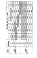
- 6 is a table showing a commutation pattern example 2 for the PWM inverter circuit 2 in a normal operation mode and a braking operation mode by the motor control device 10 of FIG. 1.
- 1 is a simulation result of the electric tool of FIG.
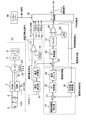
- FIG. 1 is a block diagram showing a configuration example of a power tool according to an embodiment of the present invention.
- the power tool according to the embodiment includes, for example, a motor 1 that is a permanent magnet synchronous motor, a PWM inverter circuit 2, a gear 3, a chuck 4, a rechargeable battery 5, a capacitor 6, and a motor control device 10.
- the motor control device 10 includes a current detection unit 11, a current calculation unit 12, an overcurrent detection unit 51, a speed control unit 52, a current control unit 53, and a gate control unit 20. .
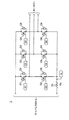
- FIG. 2 is a block diagram showing a detailed configuration example 1 of the PWM inverter circuit 2 of FIG.
- the PWM inverter circuit 2 includes, for example, six switching elements Q1 to Q6 such as MOSFETs, and three current detection resistors 7A, 7B, and 7C (having resistance values Rx, Ry, and Rz). .
- the voltages of the current detection resistors 7A, 7B, and 7C are input to the current detection unit 11 of FIG. 1 and converted into current values that flow through each phase of the PWM inverter circuit.
- gate control signals G1 to G6 from the gate control unit 20 of FIG. 1 are applied to the gates of the switching elements Q1 to Q6.
- Diodes D1 to D6 connected in antiparallel to the switching elements Q1 to Q6 are parasitic diodes or the like of the switching elements Q1 to Q6.
- the embodiment of the PWM inverter circuit 2 in FIG. 2 is a so-called three-shunt three-phase PWM bridge.
- the present invention is not limited to this, and the current on the DC side can be obtained with one current detection resistor as shown in FIG. Even the one-shunt three-phase PWM bridge PWM inverter circuit 2 to be detected is applicable.
- the element current of the switching element can be obtained when the peak value of the current flowing through the current detection resistor 7A is detected, and the battery current can be obtained when the average value of the current flowing through the current detection resistor 7A is detected. .
- the instantaneous current of the current supplied to the PWM inverter circuit 2 and a predetermined calculation current are detected, and the switching elements Q1 to Q6, the circuit, and the rechargeable battery 5 are protected. Details will be described later.
- the DC voltage from the rechargeable battery 5 is supplied to the PWM inverter circuit 2 through the capacitor 6.
- the PWM inverter circuit 2 performs PWM modulation on the supplied DC voltage with the six gate drive signals G1 to G6 from the gate control unit 20, converts the DC voltage into an AC voltage, and outputs the AC voltage to the motor 1.
- the rotation of the motor 1 is transmitted to the chuck 4 of the electric tool via the gear 3.
- the gate control unit 20 includes motor rotation position signals Hu, Hv, Hw from the Hall elements 41 to 43 provided in the motor 1, a PWM signal from the current control unit 53, and a gate block from the overcurrent detection unit 51. Based on the signal, a speed detection value and gate drive signals G1 to G6 are generated.
- the voltages detected by the current detection resistors 7A, 7B, and 7C are output to the current detection unit 11, and the current detection unit 11 converts the voltage into a corresponding current value to calculate the non-inverting input terminal of the comparator 13 and the current calculation.
- the current calculation unit 12 for example, the vicinity of the peak values of the currents Ix, Iy, and Iz flowing in each phase of the PWM inverter circuit is smoothed and output to the subtracter 25.
- the overcurrent detection unit 51 includes a comparator 13 and a maximum current signal generator 14.
- the comparator 13 compares the instantaneous current signal from the current detector 11 with the maximum current value from the maximum current signal generator 14, generates a gate block signal from the comparison result, and outputs it to the gate controller 20. To do. When the instantaneous current exceeds the maximum current value, the gate control unit 20 immediately stops driving the PWM inverter circuit 2 and protects the switching element.
- the speed control unit 52 includes an absolute value calculator 30, a speed target value generator 21, a subtractor 22, a PI controller 23 that performs proportional-integral control on the motor speed, and a current limiter 24.
- the absolute value calculator 30 calculates the absolute value of the speed detection value from the gate controller 20 and outputs it to the subtractor 22.
- the subtracter 22 subtracts the absolute value of the speed detection value from the speed target value from the speed target value generator 21 and outputs the subtraction result to the PI controller 23.
- the PI controller 23 performs proportional-integral control on the motor speed based on the input subtraction result, and outputs a current target value for the control to the subtracter 25 via the current limiter 24.
- the current limiter 24 prevents the overcurrent in advance and protects the circuit and the rechargeable battery 5 by limiting the current target value corresponding to the speed target value within a predetermined value.
- the current controller 53 includes a subtracter 25, a PI controller 26, a limiter 27, a comparator 28, and a triangular wave generator 29.
- the subtracter 25 subtracts the average current signal from the current calculation unit 12 from the current target value signal indicating the current target value, and outputs a signal of the current control value as a subtraction result to the PI controller 26.
- the PI controller 26 performs proportional-integral control on the current control value, and outputs the control signal to the non-inverting input terminal of the comparator 28 via the limiter 27.
- the limiter 27 controls the amplitude value of the PWM signal output from the comparator 28 within a predetermined value.
- the comparator 28 compares the control signal from the limiter 27 with the triangular wave from the triangular wave generator 29 to generate a PWM signal for driving the motor 1 by PWM modulation, and outputs the PWM signal to the gate control unit 20. .
- the gate control unit 20 generates six gate drive signals G1 to G6 based on the motor rotation position signal from the Hall element, the PWM signal, and the gate block signal, and outputs them to the PWM inverter circuit 2 to generate a PWM inverter. The operation of the circuit 2 is controlled.
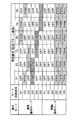
- FIG. 4 is a table showing a commutation pattern example 1 for the PWM inverter circuit 2 in the normal operation mode and the braking operation mode by the motor control device 10 of FIG.
- the gate control unit 20 turns on the switching elements Q2, Q4, and Q6 sequentially and sequentially synchronizes with the gates to the switching elements Q1, Q3, and Q5 with a half cycle delay.
- the motor 1 is rotated at a predetermined speed by PWM-modulating the control signals G1, G3, and G5.
- a stop signal is output from the trigger lever 60 to the gate control unit 20 when the motor is normally stopped by an operation such as a user returning the trigger lever, for example.
- the gate control unit 20 immediately shifts from the normal operation mode to the braking operation mode, turns off the high-side switching elements Q1, Q3, and Q5, and controls the gate control signal G2 to the low-side switching elements Q2, Q4, and Q6.
- G4, and G6 are PWM-modulated to decelerate and stop at a predetermined speed while braking the motor 1.
- the gate control signals G2, G4, G6 to the low-side switching elements Q2, Q4, Q6 are PWM-modulated so as to limit the current flowing through the motor 1 and the switching elements Q2, Q4, Q6 to a predetermined limit value.
- the current flowing through the switching element during braking can be suppressed.
- the current of each switching element Q2, Q4, Q6 on the low side of the PWM inverter circuit 2 is detected, and the current flowing through the motor 1 and the switching elements Q2, Q4, Q6 during braking is limited to a predetermined limit current value. Control to do.
- the low-side switching elements Q2, Q4, Q6 are switched to boost the induced electromotive voltage of the motor 1 and regenerate the rechargeable battery 5. Therefore, as shown in FIG. 4, the commutation pattern of the switching element is switched according to the usage status of the power tool. Note that the commutation pattern shown in FIG. 4 is an example, and the present invention is not limited to this.
- the low-side switching element may be turned off in the braking operation mode, and the high-side switching element may be PWM-controlled.
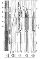
- FIG. 6 is a simulation result of the electric tool of FIG. 1, and (a) gate control signal, (b) motor rotation speed, (c) motor current detection value Imval and battery regeneration current Ib, (d) motor current Iu. , Iv, Iw, and (e) a timing chart of the battery voltage Vdc.
- a portion where the waveform changes in a complicated manner is represented by hatching.
- the motor 1 that rotates at a constant speed during normal operation decelerates and stops at a constant speed during braking.
- the detected value Imval of the motor current is limited to a predetermined current limit value Imref during braking. It can be seen that the battery voltage Vdc rises during braking, the regenerative current Ib flows through the rechargeable battery 5, and the inertia energy is regenerated.
- the following specific effects are obtained.
- Regenerating inertial energy to the rechargeable battery 5 can shorten the braking time. Further, the heat generation of the motor 1 can be reduced, and the continuous use time of the tool can be extended.
- (3) Tool protection and operability improvement can be achieved by changing the current limit value Imref according to the operation state of the electric tool.
- a rotary power tool of a drill driver has been described.
- the present invention is not limited to this and can be applied to an impact power tool.
- the motor control device 10 may be configured mainly with hardware or may be configured mainly with software.
Landscapes
- Engineering & Computer Science (AREA)
- Power Engineering (AREA)
- Mechanical Engineering (AREA)
- Control Of Motors That Do Not Use Commutators (AREA)
- Portable Power Tools In General (AREA)
- Inverter Devices (AREA)
- Control Of Ac Motors In General (AREA)
Abstract
本発明に係る電動工具の制御回路は、永久磁石同期モータと、複数のスイッチング素子と、永久磁石同期モータを駆動するPWMインバータ回路とを備えた電動工具の制御回路であって、制御回路は、PWMインバータ回路に流れる電流を検出する電流検出手段を備え、永久磁石同期モータの制動時において、永久磁石同期モータ及びPWMインバータ回路の各スイッチング素子に流れる電流を所定の電流制限値に制限する。また同時に、PWMインバータ回路のローサイドまたはハイサイドのスイッチング素子をスイッチングさせることで、永久磁石同期モータの誘導起電圧を昇圧し、電池に回生する。
Description
本発明は、例えば永久磁石同期モータを用いた電動工具の制御回路及び制御方法、並びに電動工具に関する。
一般にドリルドライバ、インパクト工具等の電動工具は、停止時、制動を行うことで、操作性や応答性の改善を図っている。
その一例として、特許文献1では、三相ブラシレスモータを駆動源とする電動工具において、三相ブラシレスモータの回転を低下若しくは停止させる際には、三相ブラシレスモータの各端子間を短絡することで制動力を発生させる、所謂短絡ブレーキ(短絡制動)が提案されている。
また、特許文献2では、スイッチング素子に並列に設けられたダイオードを介して前記ブレーキ電流を流すことができ、しかも、前記スイッチング素子に流れるブレーキ電流が減少方向にあるタイミングで前記スイッチング素子をオン状態からオフ状態へ切り換えることを特徴とする電動工具の制動装置が提案されている。
しかしながら、上記の特許文献1及び2の方法では、下記のような問題点があった。
(1)制動時にスイッチング素子に流れる電流が制御できず、素子が壊れる。
(2)制動時に流れる最大電流に合わせて電流定格の大きな素子が必要である。
(3)工具回転時の慣性エネルギーを主にモータ巻線の電気抵抗のみで消費させるため制動に時間が掛かる。また、モータの発熱が大きい。
(4)制動力、制動時間等が制御できない。
(1)制動時にスイッチング素子に流れる電流が制御できず、素子が壊れる。
(2)制動時に流れる最大電流に合わせて電流定格の大きな素子が必要である。
(3)工具回転時の慣性エネルギーを主にモータ巻線の電気抵抗のみで消費させるため制動に時間が掛かる。また、モータの発熱が大きい。
(4)制動力、制動時間等が制御できない。
本発明の目的は以上の問題点を解決し、従来技術と比較してより安価で信頼性の高い電動工具の制御回路及び制御方法、並びに電動工具を提供することにある。
第1の発明にかかる電動工具の制御回路は、永久磁石同期モータと、複数のスイッチング素子と、前記永久磁石同期モータを駆動するPWMインバータ回路とを備えた電動工具の制御回路であって、
前記制御回路は、
前記PWMインバータ回路に流れる電流を検出する電流検出手段を備え、
前記永久磁石同期モータの制動時において、前記永久磁石同期モータ及び前記PWMインバータ回路に流れる電流を所定の電流制限値に制限することを特徴とする。
前記制御回路は、
前記PWMインバータ回路に流れる電流を検出する電流検出手段を備え、
前記永久磁石同期モータの制動時において、前記永久磁石同期モータ及び前記PWMインバータ回路に流れる電流を所定の電流制限値に制限することを特徴とする。
前記電動工具の制御回路において、前記PWMインバータ回路は前記永久磁石同期モータと電池との間に設けられ、
前記制御回路は、前記永久磁石同期モータの制動時において、前記PWMインバータ回路のローサイドまたはハイサイドのスイッチング素子をスイッチングさせることで、前記永久磁石同期モータの誘導起電圧を昇圧し、前記電池に回生することを特徴とする。
前記制御回路は、前記永久磁石同期モータの制動時において、前記PWMインバータ回路のローサイドまたはハイサイドのスイッチング素子をスイッチングさせることで、前記永久磁石同期モータの誘導起電圧を昇圧し、前記電池に回生することを特徴とする。
また、前記電動工具の制御回路において、前記制御回路は、前記電動工具の動作モードに応じて、前記電流制限値を変化させることを特徴とする。
第2の発明に係る電動工具の制御方法は、
永久磁石同期モータと、複数のスイッチング素子と、前記永久磁石同期モータを駆動するPWMインバータ回路とを備えた電動工具の制御回路により実行される電動工具の制御方法であって、
前記制御回路が、前記PWMインバータ回路に流れる電流を検出する電流検出ステップと、前記制御回路が、前記永久磁石同期モータの制動時において、前記永久磁石同期モータ及び前記PWMインバータ回路に流れる電流を所定の電流制限値に制限する電流制限ステップとを含むことを特徴とする。
永久磁石同期モータと、複数のスイッチング素子と、前記永久磁石同期モータを駆動するPWMインバータ回路とを備えた電動工具の制御回路により実行される電動工具の制御方法であって、
前記制御回路が、前記PWMインバータ回路に流れる電流を検出する電流検出ステップと、前記制御回路が、前記永久磁石同期モータの制動時において、前記永久磁石同期モータ及び前記PWMインバータ回路に流れる電流を所定の電流制限値に制限する電流制限ステップとを含むことを特徴とする。
第3の発明に係る電動工具は、
電池と、永久磁石同期モータと、複数のスイッチング素子と、前記永久磁石同期モータを駆動するPWMインバータ回路を備えた電動工具であって、
前記電動工具の制御回路を備えたことを特徴とする。
電池と、永久磁石同期モータと、複数のスイッチング素子と、前記永久磁石同期モータを駆動するPWMインバータ回路を備えた電動工具であって、
前記電動工具の制御回路を備えたことを特徴とする。
従って、本発明に係る電動工具の制御回路及び制御方法等によれば、制動時に素子電流を制限するように制御することで、素子コストの軽減と工具の信頼性向上が図れる。また、慣性エネルギーを充電池5に回生することで、制動時間を短縮できる。加えて、モータの発熱の軽減が図れ、工具の連続使用時間も延ばせる。
図1は本発明の一実施形態にかかる電動工具の構成例を示すブロック図である。図1において、実施形態にかかる電動工具は、例えば永久磁石同期モータであるモータ1と、PWMインバータ回路2と、ギア3と、チャック4と、充電池5と、キャパシタ6と、モータ制御装置10とを備えて構成する。ここで、モータ制御装置10は、電流検出部11と、電流計算部12と、過電流検出部51と、速度制御部52と、電流制御部53と、ゲート制御部20とを備えて構成する。
図2は図1のPWMインバータ回路2の詳細構成例1を示すブロック図である。図2において、PWMインバータ回路2は、例えば、MOSFET等のスイッチング素子Q1~Q6、6個と、電流検出抵抗7A,7B,7C(抵抗値Rx,Ry,Rzを有する)3個で構成される。電流検出抵抗7A,7B,7Cの電圧は図1の電流検出部11に入力され、PWMインバータ回路各相に流れる電流値に変換される。また、各スイッチング素子Q1~Q6のゲートには、図1のゲート制御部20からのゲート制御信号G1~G6が印加される。各スイッチング素子Q1~Q6に逆並列に接続されているダイオードD1~D6は各スイッチング素子Q1~Q6の寄生ダイオード等である。
なお、図2のPWMインバータ回路2の実施形態は所謂3シャントの三相PWMブリッジであるが、本発明はこれに限らず、図3に示すような電流検出抵抗1個で直流側の電流を検出する1シャントの三相PWMブリッジのPWMインバータ回路2であっても適用可能である。図3の詳細構成例2においては、電流検出抵抗7Aに流れる電流のピーク値を検出するとスイッチング素子の素子電流が、電流検出抵抗7Aに流れる電流の平均値を検出すると電池電流を得ることができる。
本実施形態にかかるモータ制御装置10では、PWMインバータ回路2に供給される電流の瞬時電流と所定の計算電流を検出して、スイッチング素子Q1~Q6と回路及び充電池5の保護を行う。具体的には詳細後述する。
図1において、充電池5からのDC電圧はキャパシタ6を介してPWMインバータ回路2に供給される。PWMインバータ回路2は、供給されるDC電圧を、ゲート制御部20からの6個のゲート駆動信号G1~G6でPWM変調し、交流の電圧に変換してモータ1に出力する。ここで、モータ1の回転はギア3を介して電動工具のチャック4に対して伝達される。ゲート制御部20は、モータ1に設けられたホール素子41~43からのモータ回転位置信号Hu,Hv,Hwと、電流制御部53からのPWM信号、及び、過電流検出部51からのゲートブロック信号に基づいて、速度検出値とゲート駆動信号G1~G6を生成する。
電流検出抵抗7A,7B,7Cで検出された電圧は電流検出部11に出力され、電流検出部11は当該電圧を、対応する電流値に変換して比較器13の非反転入力端子及び電流計算部12に出力する。電流計算部12では、例えば、PWMインバータ回路の各相に流れる電流Ix,Iy,Izのピーク値付近を平滑して、減算器25に出力する。
過電流検出部51は、比較器13と、最大電流信号発生器14とを備えて構成する。比較器13は、電流検出部11からの瞬時電流信号と、最大電流信号発生器14からの最大電流値とを比較し、その比較結果からゲートブロック信号を発生させて、ゲート制御部20に出力する。ゲート制御部20は、瞬時電流が最大電流値を超える場合、PWMインバータ回路2の駆動を直ちに停止させ、スイッチング素子を保護する。
速度制御部52は、絶対値演算器30と、速度目標値発生器21と、減算器22と、モータ速度に対して比例積分制御を行うPI制御器23と、電流リミッタ24とを備えて構成する。絶対値演算器30は、ゲート制御部20からの速度検出値の絶対値を演算して減算器22に出力する。減算器22は、速度目標値発生器21からの速度目標値から速度検出値の絶対値を減算し、その減算結果をPI制御器23に出力する。PI制御器23は、入力される減算結果に基づいて、モータ速度に対して比例積分制御を行って、その制御のための電流目標値を、電流リミッタ24を介して減算器25に出力する。ここで、電流リミッタ24は、速度目標値に対応する電流目標値を所定値以内に制限することで、過電流を事前に予防し、回路及び充電池5を保護する。
電流制御部53は、減算器25と、PI制御器26と、リミッタ27と、比較器28と、三角波発生器29とを備えて構成する。減算器25は、電流目標値を示す電流目標値信号から電流計算部12からの平均電流信号を減算することで、減算結果の電流制御値の信号をPI制御器26に出力する。PI制御器26は、電流制御値に対して比例積分制御を行って、その制御信号をリミッタ27を介して比較器28の非反転入力端子に出力する。ここで、リミッタ27は、比較器28が出力するPWM信号の振幅値を所定値以内に制御する。比較器28は、リミッタ27からの制御信号と、三角波発生器29からの三角波とを比較することで、モータ1をPWM変調で駆動するためのPWM信号を発生してゲート制御部20に出力する。
ゲート制御部20は、ホール素子からのモータ回転位置信号と、PWM信号、ゲートブロック信号に基づいて、6個のゲート駆動信号G1~G6を発生してPWMインバータ回路2に出力することでPWMインバータ回路2の動作を制御する。
図4は図1のモータ制御装置10による通常動作モード及び制動動作モードにおけるPWMインバータ回路2に対する転流パターン例1を示す表である。
図4において、通常動作モードにおいては、ゲート制御部20は、スイッチング素子Q2,Q4,Q6を順次選択的にオンしながら、それに同期して半周期遅れでスイッチング素子Q1,Q3,Q5へのゲート制御信号G1,G3,G5をPWM変調することで、モータ1を所定の速度で回転させる。
一方、例えばユーザがトリガーレバーを戻す等の操作でモータを通常停止させる場合において、トリガーレバー60からゲート制御部20に停止信号が出力される。このとき、ゲート制御部20は、即座に通常動作モードから制動動作モードに移行し、ハイサイドのスイッチング素子Q1,Q3,Q5をオフ、ローサイドのスイッチング素子Q2,Q4,Q6へのゲート制御信号G2,G4,G6をPWM変調することで、モータ1を制動させながら所定の速度で減速、停止させる。また同時にモータ1及びスイッチング素子Q2,Q4,Q6に流れる電流を所定の制限値に制限するようにローサイドのスイッチング素子Q2,Q4,Q6へのゲート制御信号G2,G4,G6をPWM変調することにより、制動時にスイッチング素子に流れる電流を抑制できる。
本実施形態では、PWMインバータ回路2のローサイドの各スイッチング素子Q2,Q4,Q6の電流を検出して、制動時にモータ1とスイッチング素子Q2,Q4,Q6を流れる電流を所定の制限電流値に制限するように制御する。制動時には、ローサイドの各スイッチング素子Q2,Q4,Q6をスイッチングさせることで、モータ1の誘導起電圧を昇圧し、充電池5に回生する。従って、図4に示すように、電動工具の使用状況に応じて、スイッチング素子の転流パターンを切り替える。
なお、図4に示す転流パターンは1例であり、本発明はこれに限らず、例えば、図5に示す転流パターン例2のように、ローサイドとハイサイドのスイッチング素子の転流パターンを入れ替えて、制動動作モードにローサイドのスイッチング素子をオフし、ハイサイドのスイッチング素子をPWM制御しても構わない。
なお、図4に示す転流パターンは1例であり、本発明はこれに限らず、例えば、図5に示す転流パターン例2のように、ローサイドとハイサイドのスイッチング素子の転流パターンを入れ替えて、制動動作モードにローサイドのスイッチング素子をオフし、ハイサイドのスイッチング素子をPWM制御しても構わない。
図6は図1の電動工具のシミュレーション結果であって、(a)ゲート制御信号、(b)モータ回転数、(c)モータ電流の検出値Imval及び電池回生電流Ib、(d)モータ電流Iu,Iv,Iw、並びに(e)電池電圧Vdcのタイミングチャートである。図6において、図示の便宜上、波形が複雑に変化する部分をハッチングで表すものとする。
図6から明らかなように、通常動作時に一定回転しているモータ1が制動時は一定速度で減速し停止すること。モータ電流の検出値Imvalが制動時は所定の電流制限値Imrefに制限されること。電池電圧Vdcが制動時に上昇し、充電池5に回生電流Ibが流れて、慣性エネルギーが回生されていることがわかる。
以上説明したように、本実施形態によれば、以下の特有の効果を有する。
(1)スイッチング素子の電流を制御して制限することで、素子コストの軽減と工具の信頼性向上が図れる。
(2)慣性エネルギーを充電池5に回生することで、制動時間を短縮できる。また、モータ1の発熱の軽減が図れ、さらには工具の連続使用時間も延ばせる。
(3)電流制限値Imrefを電動工具の動作状況に応じて変化させることで、工具保護と操作性改善が図れる。
(1)スイッチング素子の電流を制御して制限することで、素子コストの軽減と工具の信頼性向上が図れる。
(2)慣性エネルギーを充電池5に回生することで、制動時間を短縮できる。また、モータ1の発熱の軽減が図れ、さらには工具の連続使用時間も延ばせる。
(3)電流制限値Imrefを電動工具の動作状況に応じて変化させることで、工具保護と操作性改善が図れる。
以上の実施形態においては、例えばドリルドライバの回転式電動工具について説明しているが、本発明はこれに限らず、インパクト式電動工具にも適用することができる。
以上の実施形態においては、モータ制御装置10は、ハードウェアを主体に構成されたものであっても、ソフトウェアを主体に構成されたものであってもよい。
1 モータ
2 PWMインバータ回路
3 ギア
4 チャック
5 充電池
6 キャパシタ
7A,7B,7C 電流検出抵抗
10 モータ制御装置
11 電流検出部
12 電流計算部
13 比較器
14 最大電流信号発生器
20 ゲート制御部
21 速度目標値発生器
22 減算器
23 PI制御器
24 電流リミッタ
25 減算器
26 PI制御器
27 リミッタ
28 比較器
29 三角波発生器
30 絶対値演算器
41~43 ホール素子
51 過電流検出部
52 速度制御部
53 電流制御部
60 トリガーレバー
D1~D6 逆流阻止用ダイオード
G1~G6 ゲート制御信号
Ix,Iy,Iz 検出電流値
Q1~Q6 スイッチング素子
Claims (5)
- 永久磁石同期モータと、複数のスイッチング素子と、前記永久磁石同期モータを駆動するPWMインバータ回路とを備えた電動工具の制御回路であって、
前記制御回路は、
前記PWMインバータ回路に流れる電流を検出する電流検出手段を備え、
前記永久磁石同期モータの制動時において、前記永久磁石同期モータ及び前記PWMインバータ回路に流れる電流を所定の電流制限値に制限することを特徴とする電動工具の制御回路。 - 前記PWMインバータ回路は前記永久磁石同期モータと電池との間に設けられ、
前記制御回路は、前記永久磁石同期モータの制動時において、前記PWMインバータ回路のローサイドまたはハイサイドのスイッチング素子をスイッチングさせることで、前記永久磁石同期モータの誘導起電圧を昇圧し、前記電池に回生することを特徴とする請求項1記載の電動工具の制御回路。 - 前記制御回路は、前記電動工具の動作モードに応じて、前記電流制限値を変化させることを特徴とする請求項1又は2記載の電動工具の制御回路。
- 永久磁石同期モータと、複数のスイッチング素子と、前記永久磁石同期モータを駆動するPWMインバータ回路を備えた電動工具の制御回路により実行される電動工具の制御方法であって、
前記制御回路が、前記PWMインバータ回路に流れる電流を検出する電流検出ステップと、
前記制御回路が、前記永久磁石同期モータの制動時において、前記永久磁石同期モータ及び前記PWMインバータ回路の各スイッチング素子に流れる電流を所定の電流制限値に制限する電流制限ステップとを含むことを特徴とする電動工具の制御方法。 - 電池と、永久磁石同期モータと、複数のスイッチング素子と、前記永久磁石同期モータを駆動するPWMインバータ回路とを備えた電動工具であって、
請求項1~3のうちのいずれか1つに記載の電動工具の制御回路を備えたことを特徴とする電動工具。
Priority Applications (4)
| Application Number | Priority Date | Filing Date | Title |
|---|---|---|---|
| EP19758308.1A EP3672066A4 (en) | 2018-02-22 | 2019-01-11 | CONTROL CIRCUIT FOR ELECTRIC TOOL |
| JP2020502071A JPWO2019163320A1 (ja) | 2018-02-22 | 2019-01-11 | 電動工具の制御回路 |
| US16/648,905 US20200287482A1 (en) | 2018-02-22 | 2019-01-11 | Control circuit for electric tool |
| CN201980004764.9A CN111164881A (zh) | 2018-02-22 | 2019-01-11 | 电动工具的控制电路 |
Applications Claiming Priority (2)
| Application Number | Priority Date | Filing Date | Title |
|---|---|---|---|
| JP2018029904 | 2018-02-22 | ||
| JP2018-029904 | 2018-02-22 |
Publications (1)
| Publication Number | Publication Date |
|---|---|
| WO2019163320A1 true WO2019163320A1 (ja) | 2019-08-29 |
Family
ID=67687631
Family Applications (1)
| Application Number | Title | Priority Date | Filing Date |
|---|---|---|---|
| PCT/JP2019/000729 Ceased WO2019163320A1 (ja) | 2018-02-22 | 2019-01-11 | 電動工具の制御回路 |
Country Status (5)
| Country | Link |
|---|---|
| US (1) | US20200287482A1 (ja) |
| EP (1) | EP3672066A4 (ja) |
| JP (1) | JPWO2019163320A1 (ja) |
| CN (1) | CN111164881A (ja) |
| WO (1) | WO2019163320A1 (ja) |
Families Citing this family (3)
| Publication number | Priority date | Publication date | Assignee | Title |
|---|---|---|---|---|
| KR102186763B1 (ko) * | 2019-04-11 | 2020-12-04 | 엘에스일렉트릭(주) | 과전류 보호 인버터 |
| US12556113B2 (en) | 2021-02-10 | 2026-02-17 | Techtronic Cordless Gp | Device and method for motor braking |
| US12316259B2 (en) * | 2021-05-29 | 2025-05-27 | Texas Instruments Incorporated | Fast deceleration of PMSM and BLDC motors using recirculation braking |
Citations (7)
| Publication number | Priority date | Publication date | Assignee | Title |
|---|---|---|---|---|
| JPS6155175B2 (ja) | 1976-11-22 | 1986-11-26 | Yoshiro Nakamatsu | |
| JPH06104000B2 (ja) | 1989-08-12 | 1994-12-14 | 松下電工株式会社 | 充電式工具用ブラシレスモータ駆動回路 |
| JPH08205316A (ja) * | 1995-01-23 | 1996-08-09 | Suzuki Motor Corp | 電動車両の速度制御方法 |
| JP2002061512A (ja) * | 2000-08-23 | 2002-02-28 | Denso Corp | 車両用冷却ファンの制御装置 |
| JP2008271612A (ja) * | 2007-04-16 | 2008-11-06 | Fujitsu Telecom Networks Ltd | モータ制御回路 |
| WO2015008486A1 (ja) * | 2013-07-18 | 2015-01-22 | パナソニックIpマネジメント株式会社 | 洗濯機 |
| JP6155175B2 (ja) * | 2013-11-18 | 2017-06-28 | 株式会社マキタ | 電動工具の制動装置 |
Family Cites Families (4)
| Publication number | Priority date | Publication date | Assignee | Title |
|---|---|---|---|---|
| US4544868A (en) * | 1984-07-20 | 1985-10-01 | General Motors Corporation | Brushless DC motor controller |
| CN100442622C (zh) * | 2003-02-18 | 2008-12-10 | 美商波特-凯博公司 | 电动工具中电池过电流的保护的安培数控制 |
| EP3051648B1 (en) * | 2013-09-27 | 2021-06-02 | Mitsubishi Electric Corporation | Inrush current limiting circuit and power conversion device |
| US10177691B2 (en) * | 2016-07-06 | 2019-01-08 | Black & Decker Inc. | Electronic braking of brushless DC motor in a power tool |
-
2019
- 2019-01-11 US US16/648,905 patent/US20200287482A1/en not_active Abandoned
- 2019-01-11 CN CN201980004764.9A patent/CN111164881A/zh active Pending
- 2019-01-11 WO PCT/JP2019/000729 patent/WO2019163320A1/ja not_active Ceased
- 2019-01-11 JP JP2020502071A patent/JPWO2019163320A1/ja not_active Withdrawn
- 2019-01-11 EP EP19758308.1A patent/EP3672066A4/en not_active Withdrawn
Patent Citations (7)
| Publication number | Priority date | Publication date | Assignee | Title |
|---|---|---|---|---|
| JPS6155175B2 (ja) | 1976-11-22 | 1986-11-26 | Yoshiro Nakamatsu | |
| JPH06104000B2 (ja) | 1989-08-12 | 1994-12-14 | 松下電工株式会社 | 充電式工具用ブラシレスモータ駆動回路 |
| JPH08205316A (ja) * | 1995-01-23 | 1996-08-09 | Suzuki Motor Corp | 電動車両の速度制御方法 |
| JP2002061512A (ja) * | 2000-08-23 | 2002-02-28 | Denso Corp | 車両用冷却ファンの制御装置 |
| JP2008271612A (ja) * | 2007-04-16 | 2008-11-06 | Fujitsu Telecom Networks Ltd | モータ制御回路 |
| WO2015008486A1 (ja) * | 2013-07-18 | 2015-01-22 | パナソニックIpマネジメント株式会社 | 洗濯機 |
| JP6155175B2 (ja) * | 2013-11-18 | 2017-06-28 | 株式会社マキタ | 電動工具の制動装置 |
Non-Patent Citations (1)
| Title |
|---|
| See also references of EP3672066A4 * |
Also Published As
| Publication number | Publication date |
|---|---|
| US20200287482A1 (en) | 2020-09-10 |
| CN111164881A (zh) | 2020-05-15 |
| JPWO2019163320A1 (ja) | 2020-09-17 |
| EP3672066A4 (en) | 2020-11-04 |
| EP3672066A1 (en) | 2020-06-24 |
Similar Documents
| Publication | Publication Date | Title |
|---|---|---|
| JP6169203B1 (ja) | 電動機制御装置および電動機制御方法 | |
| JP4752772B2 (ja) | 交流電動機の巻線切替装置及びその巻線切替システム | |
| JP5862125B2 (ja) | 電力変換装置の制御装置 | |
| EP3033288B1 (en) | Elevator braking in a battery powered elevator system | |
| JP7205176B2 (ja) | モータ駆動システム | |
| JP6173516B1 (ja) | 電動機制御装置および電動機制御方法 | |
| JP2012196725A (ja) | 電動工具 | |
| JPWO2018230142A1 (ja) | 電動工具の制御装置 | |
| WO2019163320A1 (ja) | 電動工具の制御回路 | |
| JP6407382B1 (ja) | 電動機制御装置および電動機制御方法 | |
| JP6004374B2 (ja) | モータ制御装置及びモータ制御方法 | |
| JP6230677B1 (ja) | 回転電機の制御装置および制御方法 | |
| JP6289597B1 (ja) | 車両用電源装置および車両用電源装置の制御方法 | |
| JP6983305B2 (ja) | 車両制御装置 | |
| JP6768753B2 (ja) | モータ制御装置 | |
| JP3999226B2 (ja) | 電動機制御装置 | |
| JP6342043B1 (ja) | 電動機制御装置および電動機制御方法 | |
| JP6702202B2 (ja) | 回転電機システム | |
| JP2000197204A (ja) | 電動車両の回生制動制御方法 | |
| CN108352801A (zh) | 电动机的控制装置及使用其的电动汽车 | |
| JP6203318B1 (ja) | 電動機制御装置および電動機制御方法 | |
| JP6663368B2 (ja) | モータ制御装置 | |
| JP2010035373A (ja) | 鉄道車両駆動制御装置 | |
| JP7634807B2 (ja) | 回転機の制御装置及び電動パワーステアリング装置 | |
| JP4449283B2 (ja) | Pwmインバータの制御方法 |
Legal Events
| Date | Code | Title | Description |
|---|---|---|---|
| 121 | Ep: the epo has been informed by wipo that ep was designated in this application |
Ref document number: 19758308 Country of ref document: EP Kind code of ref document: A1 |
|
| ENP | Entry into the national phase |
Ref document number: 2020502071 Country of ref document: JP Kind code of ref document: A |
|
| ENP | Entry into the national phase |
Ref document number: 2019758308 Country of ref document: EP Effective date: 20200320 |
|
| NENP | Non-entry into the national phase |
Ref country code: DE |