WO2019163569A1 - 理髪用鋏 - Google Patents
理髪用鋏 Download PDFInfo
- Publication number
- WO2019163569A1 WO2019163569A1 PCT/JP2019/004666 JP2019004666W WO2019163569A1 WO 2019163569 A1 WO2019163569 A1 WO 2019163569A1 JP 2019004666 W JP2019004666 W JP 2019004666W WO 2019163569 A1 WO2019163569 A1 WO 2019163569A1
- Authority
- WO
- WIPO (PCT)
- Prior art keywords
- hairdressing
- ring
- plate
- handle
- portions
- Prior art date
- Legal status (The legal status is an assumption and is not a legal conclusion. Google has not performed a legal analysis and makes no representation as to the accuracy of the status listed.)
- Ceased
Links
Images

Classifications
-
- B—PERFORMING OPERATIONS; TRANSPORTING
- B26—HAND CUTTING TOOLS; CUTTING; SEVERING
- B26B—HAND-HELD CUTTING TOOLS NOT OTHERWISE PROVIDED FOR
- B26B13/00—Hand shears; Scissors
- B26B13/12—Hand shears; Scissors characterised by the shape of the handles
-
- B—PERFORMING OPERATIONS; TRANSPORTING
- B26—HAND CUTTING TOOLS; CUTTING; SEVERING
- B26B—HAND-HELD CUTTING TOOLS NOT OTHERWISE PROVIDED FOR
- B26B13/00—Hand shears; Scissors
- B26B13/12—Hand shears; Scissors characterised by the shape of the handles
- B26B13/20—Hand shears; Scissors characterised by the shape of the handles with gripping bows in the handle
-
- B—PERFORMING OPERATIONS; TRANSPORTING
- B26—HAND CUTTING TOOLS; CUTTING; SEVERING
- B26B—HAND-HELD CUTTING TOOLS NOT OTHERWISE PROVIDED FOR
- B26B13/00—Hand shears; Scissors
- B26B13/28—Joints
Definitions
- the present invention relates to a hairdressing scissor used for hairdressing.
- a hairdressing scissor disclosed in Patent Document 1 is formed in a pair of blade bodies in which a blade portion, a midway portion, and a handle portion are formed in order from the tip side, and a midway portion in each blade body. And a pivot for connecting both blade bodies to each other so as to be pivotable by being sequentially inserted into the shaft support holes, and both blade portions are configured to be opened and closed by approaching or separating both handle portions.
- a hollow portion in which a viscoelastic body is enclosed is formed in a part of the handle, and the load during use by the user is reduced by making the handle lighter.
- the middle part and the handle part of the blade body are often formed by casting.
- the surface is generally improved in design by a mirror finish by a skilled worker.
- the present invention has been made in view of such points, and an object of the present invention is to provide a barber for hairdressing that is lightweight, can reduce a load during use by a user, and is inexpensive and has high design properties. There is to do.
- the present invention employs a pair of plate-like portions made of metal plates or resin materials facing each other and extending in parallel with each other as part of the structure of each handle portion.
- a pair of blade bodies in which a blade portion, a midway portion, and a handle portion are formed in order from the front end side, and a shaft support hole provided in the midway portion of each blade body are sequentially inserted and inserted.
- the following measures were taken for a hairdressing scissor including a pivot shaft that pivotally connects the two blade bodies so that the two blade portions are opened and closed by an approaching and separating operation of the portions.
- the handle portion is formed of a flat metal plate or a resin material that is opposed to each other along the axis of the pivot and that extends parallel to each other along the longitudinal direction of the blade body.
- Two plate-like portions and one or more bridging portions for bridging the first and second plate-like portions, and the first plate-like portion corresponds to a midway portion that corresponds to the second plate-like portion.
- the second plate-like portion is spaced apart from the corresponding mid-portion, and the first plate-like portion in the one handle portion is The second plate-like part in the one handle part is located on the other end side of the pivot part, and the first plate-like part in the other handle part is located on one end side of the pivot axis.
- the second plate-like portion in the other handle portion located on the other end side is located on the one end side of the pivot. That.
- the first plate part is formed with a first ring part into which a user's finger can be inserted, and the first ring part of the second plate part is formed on the first ring part.
- a second ring part into which the user's finger can be inserted is formed at the opposite position, and the region excluding the first ring part of the first plate-like part and the second ring part of the second plate-like part are excluded. In the region, a plurality of openings each having various shapes are formed.
- any one of the first and second ring portions facing each other is a thumb root side located on the base side of the thumb with the thumb inserted in a hairdressing operation.
- the other one of the first and second ring portions facing each other is a thumb tip side ring portion located on the tip side of the thumb with the thumb inserted in a hairdressing operation, and the thumb
- a notch portion is provided so as to communicate the inner region and the outer region of the thumb root side ring portion, and the width dimension of the notch portion is that of the thumb. It is characterized by being set larger than the width dimension.
- either one of the first and second ring portions facing each other is compared with either one of the first and second ring portions facing each other. It is characterized by being formed in a large dimension.
- any one of the first and second ring portions facing each other is more than the other of the first and second ring portions facing each other. It is characterized by being set to a dimension that is wide in the direction along the longitudinal direction.
- the one extension portion is provided in a handle portion on the side corresponding to the thumb during hairdressing work, and is used in a state of gripping a heel It is characterized in that it is bent so as to have an obtuse V-shaped cross section in a direction away from the palm of the person.
- At least one of the bridging portions is a resin body that fills a partial region between the first and second plate-like portions. It is characterized by that.
- a pair of the resin bodies are provided along the edges of the two handle parts on the side approaching each other, and one resin body faces the other resin body. And a contact portion that contacts the other resin body and prevents further rotation of the double blade body when the two handle portions are brought close to each other and closed. It is characterized by.
- the handle portion side of the one halfway portion protrudes along the axis of the pivot shaft, and both handle portions are brought close to each other.
- a protrusion is provided that contacts the edge on the handle portion side of the other halfway portion and prevents further rotation of the blades.
- the extension portion is fastened to the midway portion with a fastening member extending along the axis of the pivot.
- At least one of the bridging portions has a dimension changing portion capable of changing a dimension in a thickness direction of the handle portion. It is characterized by.
- either one of the both handle portions corresponds to the thumb of the user at the time of barber work
- All the other bridging portions are characterized in that a dimension in the thickness direction of the handle portion is larger than that of any one of the both handle portions.
- the handle is spaced a predetermined distance from a surface side of the first plate-like portion or a surface side of the second plate-like portion.
- a third plate-like portion made of a flat metal plate or a resin material arranged so as to extend in parallel and the first and third plate-like portions, or the first and third plate-like portions are connected 1 And at least two connecting portions.
- a third ring part into which a user's finger can be inserted is located at a position corresponding to the first ring part or the second ring part in the third plate-like part.
- the connecting portion is formed so that a user's finger can be inserted and can be fitted to the first and third ring portions, or can be fitted to the second and third ring portions. It is the ring body which has this.
- the third plate-shaped portion is formed with a curved recess opening on the back surface side, and corresponds to the curved recess of the first or second plate-shaped portion.
- the position to be provided is provided with a protrusion that can be loosely fitted into the curved recess.
- a bent portion that is bent toward the first plate-like portion is formed on the middle portion of the second plate-like portion. It is characterized by.
- the portion excluding each bridging portion between the first and second plate-like portions in each handle becomes a space without a structure. Therefore, the handle part side of the heel becomes light, and the load on the user who moves the handle part during hairdressing work can be reduced.
- the parts constituting the front and back surfaces of the handle portion are formed of a metal plate or a resin material, it is not necessary to mirror finish the surface, or the handle portion may be mirror finished. Compared to a general barber for hairdressing, which is formed by casting, it takes less time. Therefore, it is possible to reduce the number of work steps of the operator when manufacturing the cocoon, and it is possible to make the hairdressing cocoon inexpensive.
- One extension part is connected to one end side of the pivot in the middle part of one blade body, while the other extension part is connected to the other end side of the pivot part in the middle part of the other blade body. Since both the second plate-shaped parts are not connected to each middle part, when both handle parts of the assembled kite are brought close to each other, each second plate-shaped unit comes into contact with the other blade body and the kite is It has a structure that prevents it from closing.
- each pattern portion looks like a combination of a plurality of frames, the design of the entire bag can be improved.
- the thumb in the third aspect of the invention, for example, in a state where the user places the index finger toward the tip of the heel and attaches to the middle of the heel and the thumb is inclined with respect to the first and second ring portions.
- the thumb can be fitted into the notch. Therefore, even when the user holds the heel in a special posture as described above, the user can perform the opening / closing operation of the heel by firmly hooking the thumb on the handle without applying a load to the thumb.
- the thumb rotates the other of the first and second ring portions with respect to the blade body within the range of either the first or second ring portion. It becomes easy to turn to the moving fulcrum. Therefore, it becomes possible to easily switch the heel to a posture suited to the user's preference during hairdressing work.
- the posture of the heel is easily switched, particularly when the position of the hand with respect to the heel is changed by shaking the thumb in the longitudinal direction of the blade, and the hairdressing operation is performed efficiently. Will be able to.
- the sixth invention for example, in a state where the user places the index finger toward the distal end side of the heel and attaches to the middle portion of the heel and the thumb is inclined with respect to the first and second ring portions.
- the penetrating directions of the first and second ring portions are along the extending direction of the thumb. Therefore, the load applied to the thumb from the first and second ring portions is reduced, and even when the user holds the heel in a special posture as described above, the user can hook the thumb firmly on the handle portion to open and close the heel. The operation can be performed easily.
- the resin body can be seen from between the first plate-like portion and the second plate-like portion, a change is added to the design of the handle portion, and the design of the bag is further enhanced. Can do.
- the portions of the both handle portions that are in contact with each other are formed of resin, so that the impact at the time of contact can be efficiently absorbed.
- the angle around the fastening member of the extension portion with respect to the midway portion can be finely adjusted. Therefore, the fine angle between the midway part and the handle part in the heel can be changed according to the user's preference.
- the dimension in the thickness direction of each pattern portion can be changed according to the user's preference, so that it is possible to make the hairdressing bar easy to use.
- the first and second plate-like portions come into contact with each finger while being spaced apart from each other in the extending direction of each finger. It becomes like this. Therefore, the opening / closing operation of the heel during the hairdressing work of the user becomes stable, and the hair styling can be made more convenient.
- the three parallel plate-like portions support the fingers at predetermined intervals and the fingers are moved by the respective plate-like portions. Is firmly hooked in the thickness direction of the handle. Therefore, it becomes difficult for the finger to slide in the thickness direction of the handle portion and the hairdressing scissors are easily held, so that the operability of the hairdressing scissors can be improved.
- the weight distribution of the hairdressing scissors is heavier on the handle side than on the blade side, and the barycentric center of the hairdressing scissors is positioned on the user's hand, so the blade side becomes lighter and the hairdressing The operability of the vase can be further enhanced.
- the fingers when using the hairdressing scissors, the fingers are inserted into the inner side of the flexible ring body, so that the tactile sensation of the fingers with respect to the handle during the operation of the hairdressing scissors can be improved.
- the ring body since the ring body has flexibility, the ring body can be easily connected to each ring part, and the ring part and the ring body can be firmly adhered to each other.
- the third plate-like portion can be tilted with respect to the first or second plate-like portion with a flexible ring body as a fulcrum. Therefore, the third plate-shaped portion is inclined so as to correspond to the movement of the user's hand when operating the hairdressing fold, and the hairdressing ridge having good operability can be obtained.
- the projection enters the curved concave portion, so that the third plate-like portion
- the third plate-like portion rotates greatly in the circumferential direction around the center line of the ring body with respect to the first or second plate-like part. Can be prevented.
- the user's finger when the user uses the hairdressing scissors, the user's finger is less likely to be caught on the first plate-shaped portion side end of the second plate-shaped portion, so that the operability of the hairdressing scissors is improved. It can be further increased.
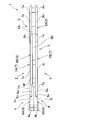
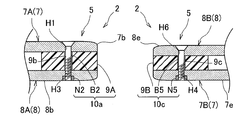
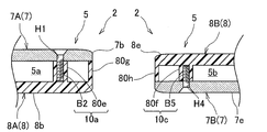
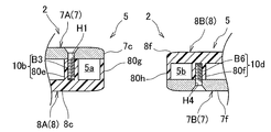
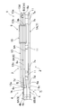
- FIG. 5 is a cross-sectional view taken along line VV in FIG. 1.
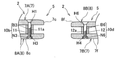
- FIG. 6 is a cross-sectional view taken along line VI-VI in FIG. 1.
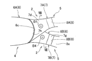
- FIG. 8 is a cross-sectional view taken along line VIII-VIII in FIG.
- FIG. 3 is a view corresponding to FIG. 1 according to Embodiment 2 of the present invention.
- FIG. 5 is a view corresponding to FIG. 4 according to Embodiment 3 of the present invention.
- FIG. 6 is a view corresponding to FIG. 5 according to Embodiment 4 of the present invention.
- FIG. 6 is a view corresponding to FIG. 6 according to Embodiment 4 of the present invention.
- FIG. 2 equivalent view which concerns on Embodiment 5 of this invention.
- It is a XV arrow line view of FIG.
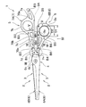
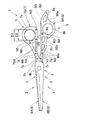
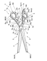
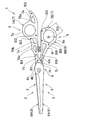
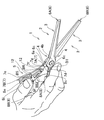
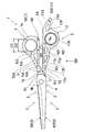
- Embodiment 1 of the Invention 1 to 3 show a hairdressing scissor 1 according to Embodiment 1 of the present invention.
- the barber 1 is used by a barber or the like during hairdressing work, and includes a pair of blade bodies 2 in which a blade portion 3, a midway portion 4, and a handle portion 5 are formed in this order from the tip side.
- the blades 2 are overlapped at both middle portions 4 so as to intersect, and each middle portion 4 is formed with a shaft support hole 4a (see FIG. 4) penetrating in the overlapping direction of the two blade bodies 2. ing.
- a pivot 4b that couples the blades 2 to each other in a rotatable manner is fitted in both the shaft support holes 4a, and the both blades 3 are opened and closed by an approaching and separating operation of both handle portions 5.
- the blade body 2 is disposed on the distal end side of the blade body 2, and has a cutting member 6 having a substantially triangular shape with a sharp tip when viewed from the front, and a first member provided on the proximal end side of the cutting member 6.
- 1 press body 7 (1st plate-shaped part) and 2nd press body 8 (2nd plate-shaped part) are provided.
- the cutting member 6 is formed by cutting a stainless steel-based blade steel material by wire electric discharge machining, and corresponds to the blade portion 3 and the midway portion 4.
- a mounting surface portion 6a On the handle 5 side of the cutting member 6, as shown in FIG. 4, there is formed a mounting surface portion 6a whose surface side is recessed in a stepped shape so that the thickness is substantially halved, and at the approximate center of the mounting surface portion 6a A screw insertion hole 6b is formed (see FIG. 8).
- the standing wall portion 6c of the mounting surface portion 6a is gently curved so as to protrude toward the handle portion 5 side.
- one of the cutting members 6 is referred to as a cutting member 6A, and the other cutting member 6 is referred to as a cutting member 6B.
- first press body 7 and the second press body 8 are formed by press-molding an aluminum alloy material, and correspond to the handle portion 5 of the present invention.
- the first press body 7 and the second press body 8 are flat plates that face each other along the axis of the pivot 4 b and extend parallel to each other along the longitudinal direction of the blade body 2. It has a shape.
- the first press body 7 and the second press body 8 in one blade body 2 are referred to as a first press body 7A and a second press body 8A, and the first press body 7 in the other blade body 2 is referred to.
- the second press body 8 will be referred to as a first press body 7B and a second press body 8B.
- the first press body 7 and the second press body 8 in the present invention have a flat plate shape, but a portion that is slightly curved or has a substantially L-shaped cross-sectional shape is an outer peripheral edge portion. There may be some.
- the first press body 7A is located on one end side of the pivot 4b, and, as shown in FIG. 1, in order from the proximal end side of the blade body 2, a little finger hook portion 7a having a substantially triangular shape in plan view, Ring portion 7b (first ring portion) with a ring finger into which a person's ring finger can be inserted, a handle portion 7c to be operated by attaching an index finger and a middle finger to the outer peripheral edge, and a middle portion 4 side from the handle portion 7c
- the ring-side ring portion 7b with the ring finger extends in a curved manner to the side of the little finger hook portion 7a, the handle portion 7c, and the extension portion 7d.
- the little finger hook 7a is formed with a substantially triangular opening 70a
- the handle 7c is formed with a substantially trapezoidal opening 70b, 70c arranged side by side along the longitudinal direction of the blade body 2. ing.
- openings 70a to 70c having various shapes are formed in the region of the first press body 7A other than the ring-side root ring portion 7b with the ring finger.
- the ring finger-side ring portion 7b is positioned on the root side of the ring finger with the ring finger inserted during hairdressing work.
- four screw insertion holes H1 are formed. Specifically, one of the four screw insertion holes H1 is formed on the opposite side of the ring-side ring portion 7b with the ring finger in the little finger hooking portion 7a, and two of the four screw insertion holes H1 are on the side with the ring finger.
- the ring part 7b and the handle part 7c are formed in a continuous part, and one of the four screw insertion holes H1 is formed in a part in which the handle part 7c and the extending part 7d are continuous.
- the middle part 4 side of the extension part 7d can be placed on the attachment surface part 6a of the cutting member 6A, and when the extension part 7d is placed on the attachment surface part 6a, The surface of the extending part 7d and the surface of the cutting member 6A are flush with each other.
- the edge portion 7h on the midway portion 4 side of the extending portion 7d has a concave shape that gently curves so as to correspond to the shape of the standing wall portion 6c of the mounting surface portion 6a of the cutting member 6A. .
- one screw insertion hole H2 is formed in the center of the extension part 7d
- the extension part 7d is placed on the mounting surface part 6a of the cutting member 6A
- the screw B1 fastening member
- the screw B1 fastening member
- the screw B1 fastening member
- the screw of the extension part 7d with respect to the cutting member 6A when fastened. Fine adjustment of the angle around B1 becomes possible. Therefore, the fine angle between the midway part 4 and the handle part 5 in one blade body 2 can be changed according to the preference of the user.
- the second press body 8A is located on the other end side of the pivot 4b, and as shown in FIG. 2, in order from the base end side of the blade body 2, a little finger hook portion 8a having a substantially triangular shape in plan view, A ring finger tip side ring part 8b (second ring part) into which the user's ring finger can be inserted, and a handle part 8c to be operated by attaching an index finger and a middle finger to the outer peripheral edge part, a little finger hook part 8a, a ring finger
- the tip side ring part 8b and the handle part 8c have shapes corresponding to the little finger hook part 7a, the ring finger-side root ring part 7b and the handle part 7c, respectively.
- the second press body 8A has no extending portion 7d like the first press body 7A and is separated from the cutting member 6A (see FIG. 3).
- the ring finger tip side ring portion 8b is positioned on the tip side of the ring finger with the ring finger inserted during hairdressing work.
- the little finger hook 8a has an opening 80a having a shape corresponding to the opening 70a formed in the little finger hook 7a, and the handle 8c corresponds to the openings 70b and 70c formed in the handle 7c. Opening portions 80b and 80c having a shape to be formed are formed.
- screw insertion holes H3 are formed at positions corresponding to the screw insertion holes H1 of the first press body 7A in the second press body 8A.
- a substantially square bar-shaped first resin body 9A (bridge portion) extending along the longitudinal direction of the blade body 2 is provided on the other side. It is provided along the edge on the blade body 2 side.
- the first resin body 9A bridges the first press body 7A and the second press body 8A, and is provided so as to fill a partial region between the first press body 7A and the second press body 8A. ing.
- a contact portion 9a having a substantially triangular shape in a front view protruding toward the other blade body 2 is provided, and the contact portion 9a injects the first resin body 9A. It is integrally formed when molding by molding.
- screw insertion holes 9b are formed at positions corresponding to the screw insertion holes H1 and H3 in the first resin body 9A, and the screw insertion holes H1, screw insertion holes 9b, and screw insertion holes H3 are formed.
- the screw B2 is inserted through the screw B2 and the nut B2 and the first press body 7A, the first resin body 9A, and the second press body 8A are sandwiched between the first press body 7A and the first resin body 9A. And the 2nd press body 8A is united.
- FIG. 6 there is a screw insertion hole 11a between the screw insertion holes H1 and H3 facing each other in the region not corresponding to the first resin body 9A in the first press body 7A and the second press body 8A.
- a cylindrical collar 11 (bridging portion) is provided, and the screw B3 is inserted through the screw insertion hole H1, the screw insertion hole 11a, and the screw insertion hole H3 in this order, and the first press body 7A and the cylindrical collar are formed by the screw B3 and the nut N3.
- 11 and the second press body 8A are sandwiched so that the first press body 7A, the cylindrical collar 11 and the second press body 8A are integrated.
- the first resin body 9A, the screw B2 and the nut N2 constitute the dimension changing portion 10a of the present invention
- the cylindrical collar 11, the screw B3 and the nut N3 constitute the dimension changing portion 10b of the present invention.
- the first press body 7B is located on the other end side of the pivot 4b, and as shown in FIG. 2, the thumb tip side ring portion 7e into which the user's thumb can be inserted in order from the base end side of the blade body 2.
- First ring portion a handle portion 7f having a substantially triangular shape when viewed from the front, and an extending portion 7g extending from the handle portion 7f toward the midway portion 4 side. It has a shape that projects in a curved shape to the side of the handle portion 7f and the extending portion 7g.
- the thumb tip side ring portion 7e is positioned on the tip side of the thumb with the thumb inserted during hairdressing work.
- the opening portion 70d having a substantially triangular shape is formed in the handle portion 7f. That is, a characteristic-shaped opening 70d is formed in a region excluding the thumb tip side ring portion 7e of the first press body 7B.
- four screw insertion holes H4 are formed. Specifically, one of the four screw insertion holes H4 is formed on the opposite side of the handle portion 7f of the thumb tip side ring portion 7e, and two of the four screw insertion holes H4 are thumb tip side rings.
- the part 7e and the handle part 7f are formed in a continuous part, and one of the four screw insertion holes H4 is formed in a part in which the handle part 7f and the extending part 7g are continuous.
- the middle part 4 side of the extension part 7g can be placed on the attachment surface part 6a of the cutting member 6B, and when the extension part 7g is placed on the attachment surface part 6a, The surface of the extending part 7g and the surface of the cutting member 6B are flush with each other.
- the edge portion 7j on the midway portion 4 side of the extending portion 7g has a concave shape that gently curves so as to correspond to the shape of the standing wall portion 6c of the mounting surface portion 6a of the cutting member 6B. .
- one screw insertion hole H5 is formed in the center of the extension part 7g, the extension part 7g is placed on the mounting surface part 6a of the cutting member 6B, and The screw B4 (fastening member) is inserted into the screw insertion hole 6b and the screw insertion hole H5 formed in the mounting surface portion 6a, and the cutting member 6B and the extending portion 7g are sandwiched between the screw B4 and the nut N4.
- the extending portion 7g is connected to the cutting member 6B.
- the extending part 7g is fastened to the cutting member 6B using the screw B4 in a posture extending along the axis of the pivot 4b, the screw of the extending part 7g with respect to the cutting member 6B when fastened. Fine adjustment of the angle around B4 becomes possible. Therefore, the fine angle between the midway part 4 and the handle part 5 in the other blade body 2 can be changed according to the user's preference.
- the 2nd press body 8B is located in the one end side of the pivot 4b, and as shown in FIG. 1, from the base end side of the blade body 2, the thumb side ring part 8e (with thumb) which can insert a user's thumb is inserted.
- a second ring portion) and a handle portion 8f having a substantially triangular shape when viewed from the front.
- the root side ring portion 8e with the thumb and the handle portion 8f have shapes corresponding to the tip end side ring portion 7e and the handle portion 7f, respectively. There is no.
- the second press body 8B has no extending portion 7g like the first press body 7B and is separated from the cutting member 6B (see FIG. 3).
- the thumb-side ring part 8e is positioned on the base side of the thumb with the thumb inserted during hairdressing work, and the dimension along the longitudinal direction of the blade body 2 in the thumb-side ring part 8e. D1 is set larger than the dimension D2 in the direction along the longitudinal direction of the blade body 2 in the thumb tip side ring portion 7e.
- An opening 80d having a substantially triangular shape is formed in the handle portion 8f. That is, an opening 80d having a characteristic shape is formed in a region of the second press body 8B excluding the thumb-side root ring portion 8e.
- screw insertion holes H6 are formed at positions corresponding to the screw insertion holes H4 of the first press body 7B in the second press body 8B.
- the substantially square-bar-shaped 2nd resin body 9B (bridge part) extended along the longitudinal direction of the blade body 2 is one side. It is provided along the edge on the blade body 2 side.
- the second resin body 9B bridges the first press body 7B and the second press body 8B, and is provided so as to fill a partial region between the first press body 7B and the second press body 8B.
- screw insertion holes 9c are formed at positions corresponding to the screw insertion holes H4 and H6 of the second resin body 9B, and the screw insertion holes H6, screw insertion holes 9c and screw insertion holes H4 are formed.
- the screws B5 are inserted through the screw B5 and the nut N5, and the first press body 7B, the second resin body 9B, and the second press body 8B are sandwiched between the first press body 7B and the second resin body 9B. And the 2nd press body 8B is united.
- the second resin body 9B, the screw B5, and the nut N5 constitute the dimension changing portion 10c of the present invention
- the cylindrical collar 12, the screw B6, and the nut N6 constitute the dimension changing portion 10d of the present invention. 2
- the dimension in the thickness direction of the handle portion 5 of the other blade body 2 can be changed. Therefore, the dimension in the thickness direction of the handle 5 in the other blade body 2 can be changed according to the user's preference, so that the hairdressing scissors 1 that are easy to use can be obtained.
- the first resin body 9A and the cylindrical collar 11 are formed to have larger dimensions in the thickness direction of the handle 5 than the second resin body 9B and the cylindrical collar 12. Accordingly, when the user's index finger and middle finger are attached to the outer peripheral edges of the handle portions 7c and 8c, the handle portions 7c and 8c come into contact with each finger while being spaced apart in the extension direction of each finger. The opening / closing operation of the hairdressing heel 1 at the time of the user's hairdressing work becomes stable, and the hairdressing heel 1 can be made easy to use.
- the first and second resin bodies 9A and 9B between the first press body 7 and the second press body 8 in each handle portion 5 are assembled. And the part except the cylindrical collars 11 and 12 becomes a space without a structure. Therefore, the handle 5 side of the heel 1 becomes light, and the load on the user who moves the handle 5 during hairdressing work can be reduced.
- the parts constituting the front and back surfaces of the handle 5 are formed of a metal plate, even if the surface of the handle 5 is mirror-finished, compared with a general barber 1 for forming the handle 5 by casting. It does not take time and effort. Therefore, it is possible to reduce the work man-hours of the worker when manufacturing the heel 1 and to make the hairdressing heel 1 inexpensive.
- extension part 7d of the 1st press body 7A is connected to the one end side of the pivot 4b in the middle part 4 of one blade body 2, the other end side of the pivot 4b in the middle part 4 of the other blade body 2 Since the extended portion 7g of the first press body 7B is connected to each other, and the second press bodies 8A and 8B are not connected to the middle portions 4, the both handle portions 5 of the assembled hairdressing scissors 1 are attached.
- the second press bodies 8A, 8B are configured to avoid the hairdressing bar 1 from being closed due to contact with the counterpart blade body 2.
- each handle 5 combines a plurality of frames.
- the design of the entire ridge 1 can be enhanced.
- the thumb-side root ring portion 8e is formed to have a size larger than that of the opposing thumb tip-side ring portion 7e, the thumb is within the range of the thumb-side root ring portion 8e when the user performs a hairdressing operation.
- the thumb tip side ring portion 7e can be easily rotated with respect to the blade body 2 as a rotation fulcrum. Therefore, it becomes possible to easily switch the heel 1 to a posture that suits the user's preference during hairdressing work.
- the thumb-side root ring portion 8e is set to have a dimension that is wider in the direction along the longitudinal direction of the blade body 2 than the opposed thumb tip-side ring portion 7e.
- first and second resin bodies 9A and 9B allow the first and second resin bodies 9A and 9B to be seen from between the first press body 7 and the second press body 8, and the design of the handle 5 Since a change is added to, the design of the heel 1 can be further enhanced.
- the portions of the handle portions 5 that are in contact with each other are formed of resin, so that the impact at the time of contact is efficiently absorbed. be able to.
- the thumb root side ring part 8e is formed to have a larger size than the opposing thumb tip side ring part 7e, but the thumb tip side ring part 7e is the thumb root side ring part 8e. It may be a ridge 1 formed to have a larger size than that of.
- the heel 1 may be formed with a larger dimension than the ring-side root ring portion 7b with the ring finger opposed to the ring finger tip-side ring portion 8b, and the ring-side ring portion with the ring finger 7b may be compared with the ring finger tip-side ring portion 8b. It may be a ridge 1 formed in a large size.
- the contact portion 9a is provided in the first resin body 9A, but the contact portion 9a protruding toward the first resin body 9A is provided in the second resin body 9B. Also good.
- the contact portion 9a is formed integrally with the main body portion of the first resin body 9A.
- the contact portion 9a is formed separately from the main body portion of the first resin body 9A. You may make it assemble later.
- the first press bodies 7A and 7B are connected to the cutting members 6A and 6B by fastening with screws B1 and B4, but are cut out by joining with an adhesive or brazing.
- the first press bodies 7A and 7B may be connected to the members 6A and 6B.
- pattern part 5 in the 1st resin body 9A and the cylindrical collar 11 is formed larger than the 2nd resin body 9B and the cylindrical collar 12, it is 1st resin.
- the dimension in the thickness direction of the handle 5 in the body 9A and the cylindrical collar 11 may be the same as that of the second resin body 9B and the cylindrical collar 12, or may be formed smaller.
- Embodiment 1 of this invention although it comprises with the 1st press body 7 and the 2nd press body 8 which formed a part of pattern part 5 by press molding, the said 1st press body 7 and the 2nd press body. You may make it comprise the body 8 with the plate-shaped member cut out from the metal plate.
- Embodiment 2 of the Invention >> 9 and 10 show a hairdressing scissor 1 according to Embodiment 2 of the present invention.
- the second embodiment only a part of the structure of each handle 5 is different from that of the first embodiment, and the others are the same as those of the first embodiment. Therefore, only the parts different from the first embodiment will be described below.
- a first resin body 9A and a second resin body 9B are provided between the first press body 7A and the second press body 8A and between the first press body 7B and the second press body 8B of the second embodiment, respectively.
- the cylindrical collars 11 and 12 are all bridged between the corresponding screw insertion holes H1 and H3 and between the screw insertion holes H4 and H6.
- the inner side area and the outer side area of the thumb-side root ring portion 8e are communicated to the opposite side of the midway portion 4 of the thumb-side root ring portion 8e of the second press body 8B, and the width dimension D3 is set to the width dimension of the thumb.
- Corresponding cutouts 8i are formed. Therefore, for example, as shown in FIG. 10, the user places his index finger toward the distal end side of the heel 1 and attaches it to the middle portion 4 of the heel 1, and the thumb distal end ring portion 7e and the thumb-side root ring portion 8e.
- the thumb can be fitted into the notch 8i in the case where the thumb is held in a slanted posture. Therefore, even when the user holds the heel 1 in a special posture as described above, the user can perform the opening / closing operation of the heel 1 by firmly hooking the thumb on the handle portion 5 without applying a load to the thumb. it can.
- a pin 7i protruding portion that protrudes toward the one blade body 2 along the axis of the pivot 4b is formed on the extending portion 7g of the second embodiment.
- the pin 7i is formed on the extending portion 7g.
- the pin 7i may be formed on the extending portion 7d. When closed, the pin 7i may be brought into contact with the edge of the extending portion 7g to prevent further rotation of the double-edged body 2.
- FIG. 11 shows a hairdressing scissor 1 according to Embodiment 3 of the present invention.
- the third embodiment only the part of the first press body 7B is different from that of the first embodiment, and the other parts are the same as those of the first embodiment. Therefore, only the parts different from the first embodiment will be described below.
- the extension part 7g of the first press body 7B according to the third embodiment is bent so as to have an obtuse V-shaped cross section in a direction away from the palm of the user in a state where the heel 1 is gripped. Therefore, for example, the user places the index finger toward the distal end side of the heel 1 and attaches it to the middle portion 4 of the heel 1, and tilts the thumb diagonally with respect to the thumb distal end ring portion 7e and the thumb root side ring portion 8e. In the case where the heel 1 is held in the posture, the penetrating direction of the thumb tip side ring part 7e and the thumb root side ring part 8e follows the extending direction of the thumb.
- the extension part 7g is bent so that a cross section may become V shape, it is not restricted to this,
- the extension part 7g is formed with the metal plate of the material which is easy to bend.
- the handle 5 is bent away from the palm of the user, and the penetrating direction of the thumb tip side ring portion 7 e and the thumb root side ring portion 8 e follows the extending direction of the thumb.
- the structure may be as follows.
- Embodiment 4 of the Invention >> 12 and 13 show a hairdressing scissor 1 according to Embodiment 4 of the present invention.
- the fourth embodiment only a part of the structure of the handle 5 is different from that of the first embodiment, and the others are the same as those of the first embodiment. Therefore, only the parts different from the first embodiment will be described below.
- the second press body 8A and the second press body 8B of the first embodiment are the second plate-like portion 8A and the second plate-like portion 8B formed of a resin material, and as in the first embodiment.
- the first resin body 9A and the second resin body 9B are not provided.
- the screw insertion holes H3 and H6 as in the first embodiment are not formed, and the portion where the screw insertion holes H3 and H6 are formed in the second press bodies 8A and 8B has a boss portion. 80e and 80f are projected.
- outer peripheral wall portions 80g and 80h extending toward the outer peripheral edge portions of the corresponding first plate-like portions 7A and 7B are formed on the outer peripheral edge portions of the second plate-like portions 8A and 8B.
- the second plate-like portion 8A, the boss portion 80e and the outer peripheral wall portion 80g are integrally formed by injection molding.
- the second plate-like portion 8B, the boss portion 80f, and the outer peripheral wall portion 80h are also integrally formed by injection molding.
- a hollow portion 5a is formed in one handle portion 5 by the first plate-like portion 7A, the second plate-like portion 8A, and the outer peripheral wall portion 80g.
- a hollow portion 5b is formed in the other handle portion 5 by the first plate-like portion 7B, the second plate-like portion 8B, and the outer peripheral wall portion 80h.
- the dimension change part 10a of Embodiment 4 is comprised with the boss
- the dimension change part 10b of Embodiment 4 is comprised with the boss
- the dimension change part 10c of Embodiment 4 is shown. Is composed of a boss portion 80f and a screw B5
- the dimension changing portion 10d of the fourth embodiment is composed of a boss portion 80f and a screw B6.
- pattern part 5 are formed with the resin material, it is not necessary to mirror-finish the surface, and the handle
- the outer peripheral wall portions 80g and 80h are provided on the outer peripheral edge portions of the second plate-like portions 8A and 8B, but it is not essential to provide the outer peripheral wall portions 80g and 80h.
- the second plate-like portion 8A, the boss portion 80e and the outer peripheral wall portion 80g are integrally formed by injection molding, and the second plate-like portion 8B, the boss portion 80f and the outer peripheral wall portion 80h are formed.
- it is integrally formed by injection molding, it may have a structure in which parts formed separately are integrated and completed with an adhesive or the like.
- Embodiment 5 of the Invention >> 14 and 15 show a hairdressing scissor 1 according to Embodiment 5 of the present invention.
- the fifth embodiment only a part of the structure of each handle 5 is different from that of the first embodiment, and the others are the same as those of the first embodiment. Therefore, only the parts different from the first embodiment will be described below.
- a first bent portion 8j that is bent toward the first press body 7A is formed on the middle portion 4 side of the second press body 8A of the handle 5 in one blade body 2 of the fifth embodiment.
- the handle 5 in one blade body 2 of Embodiment 5 includes a third press body 13 obtained by press-molding a plate-like aluminum alloy material.
- the third press body 13 has a flat shape arranged on the surface side of the second press body 8A so as to extend in parallel at a predetermined interval.
- the third press body 13 and the second press body 8A Is set to be narrower than the distance between the second press body 8A and the first press body 7A.
- the third press body 13 includes, in order from the base end side of the blade body 2, a little finger hooking portion 13a having a substantially triangular shape in plan view, and an auxiliary ring portion 13b (third ring portion) into which the user's ring finger can be inserted.
- a handle portion 13c which is a portion to be operated by attaching an index finger and a middle finger to the outer peripheral edge.
- Each handle portion 8c has a corresponding shape.
- the little finger hook 13a is formed with an opening 13f having a shape corresponding to the opening 80a formed in the little finger hook 8a, and the handle 13c corresponds to the openings 80b and 80c formed in the handle 8c. Openings 13g and 13h having a shape to be formed are formed.
- a curved recess 13d that opens to the back side is formed in the little finger hook 13a of the third press body 13.
- a second bent portion 13e bent to the second press body 8A side is formed so as to correspond to the first bent portion 8j. ing.
- the ring body 15 (connection part) which connects the said 2nd press body 8A and the 3rd press body 13 is provided.
- the ring body 15 is configured so that a user's finger can be inserted, and is formed of a flexible rubber material.
- the ring body 15 is configured to connect the second press body 8A and the third press body 13 by fitting to both the ring finger tip side ring portion 8b and the auxiliary ring portion 13b.
- the screw B3 of the little finger hook portion 8a in the second press body 8A of the fifth embodiment penetrates the little finger hook portion 8a, and the tip portion protrudes from the surface of the little finger hook portion 8a.
- the portion protruding from the surface of the little finger hook portion 8a at the tip of the screw B3 constitutes the projection 14 of the present invention, and the projection 14 is loosely fitted in the curved recess 13d of the third press body 13.
- the first press body 7A, the second press body 8A, and the third press body Three side-by-side plate-shaped portions made of the press body 13 support the index finger and the middle finger at predetermined intervals, and the index finger and the middle finger are firmly hooked in the thickness direction of the handle portion 5 by each plate-shaped portion. Accordingly, the index finger and the middle finger are less likely to slip in the thickness direction of the handle 5 and the hairdressing heel 1 is easily held, so that the operability of the hairdressing heel 1 can be improved.
- the weight distribution of the hairdressing heel 1 is heavier on the handle 5 side than on the blade 3 side, and the center of gravity of the hairdressing heel 1 is positioned toward the user's hand.
- the side becomes light and the operativity of the barb 1 for hairdressing can further be improved.
- the fingers are inserted into the inner side of the flexible ring body 15, so that the touch feeling of the fingers with respect to the handle 5 during the operation of the hairdressing scissors 1 can be improved.
- the ring body 15 is flexible, the ring body 15 can be easily connected to the ring finger tip side ring part 8b and the auxiliary ring part 13b, and the ring finger tip side ring part 8b and the auxiliary ring part can be easily connected.
- the portion 13b and the ring body can be firmly attached.
- the third press body 13 can be tilted with respect to the second press body 8A with the ring body 15 having flexibility as a fulcrum. Therefore, the third press body 13 is inclined so as to correspond to the movement of the user's hand when operating the barber 1 for hairdressing, and the barb 1 for hairdressing with good operability can be obtained.
- the protrusion 14 enters the curved concave portion 13 d, and therefore the center line of the ring body 15 around the third press body 13. Even if a force is unexpectedly applied in the circumferential direction, it is possible to prevent the third press body 13 from greatly rotating in the circumferential direction around the center line of the ring body 15 with respect to the second press body 8A.
- first bent portion 8j and the second bent portion 13e are formed in the handle portion 5, when the user uses the hairdressing scissors, the user's finger is in the second press body 8A. And it becomes difficult to get caught in the 1st press body 7A side edge part of the 3rd press body 13, and the operativity of the barb 1 for hairdressing can further be improved.
- the third press body 13 is provided on the surface side of the second press body 8A, but may be provided on the surface side of the first press body 7A.
- the auxiliary ring portion 13b is formed at a position corresponding to the ring-side root ring portion 7b with the ring finger of the first press body 7A, and the ring body 15 is fitted into the ring-side root ring portion 7b with the ring finger and the auxiliary ring portion 13b.
- the 1 press body 7A and the 3rd press body 13 are connected.
- the protrusion 14 is formed on the surface side of the first press body 7 ⁇ / b> A and is loosely fitted in the curved recess 13 d of the third press body 13.
- the third press body 13 is formed of a metal plate, but may be formed of a resin material.
- the second press body 8A and the third press body 13 are connected by the ring body 15.
- the present invention is not limited to this, and for example, as in the first embodiment, a screw and a nut are used.
- the second press body 8A and the third press body 13 may be connected at a plurality of locations using a cylindrical collar.
- the present invention is suitable for hairdressing scissors used during hairdressing.
Landscapes
- Life Sciences & Earth Sciences (AREA)
- Forests & Forestry (AREA)
- Engineering & Computer Science (AREA)
- Mechanical Engineering (AREA)
- Scissors And Nippers (AREA)
Abstract
鋏(1)は、刃部(3)、中途部(4)及び柄部(5)が先端側から順に形成された一対の刃体(2)を有する。柄部(5)は、枢軸(4b)の軸心に沿って対向するとともに刃体(2)の長手方向に沿って互いに平行に延びる平坦な板状をなす第1及び第2プレス体(7、8)と、第1及び第2プレス体(7、8)を橋絡する円筒カラー(11、12)及び第1及び第2樹脂体(9A、9B)とを有する。第1プレス体(7A)は、第2プレス体(8A)よりも中途部(4)側に延びて当該中途部(4)に接続される延出部(7d)を有する一方、第2プレス体(8A)は、中途部(4)と離間している。
Description
本発明は、理髪時に使用する理髪用鋏に関する。
従来より、例えば、特許文献1に開示されている理髪用鋏は、刃部、中途部及び柄部が先端側から順に形成された一対の刃体と、該各刃体における中途部に形成された軸支孔に順に嵌挿することで両刃体を互いに回動可能に連結する枢軸とを備え、両柄部を接近又は離間させることによって両刃部が開閉するように構成されている。そして、柄部の一部には、粘弾性体が封入された中空部が形成され、柄部を軽量にすることで使用者の使用時における負荷を減らすようにしている。
ところで、特許文献1の如き理髪用鋏は、刃体における中途部及び柄部が鋳造により形成されることが多い。そして、その表面は、一般的に、熟練工が鏡面仕上げをすることによって意匠性が高められる。
しかし、鏡面仕上げは熟練の技術が必要であるので、熟練工が少なくなってきている近年においては、作業工数の増加により製造コストが嵩んでしまうという問題が発生するようになってきている。
本発明は斯かる点に鑑みてなされたものであり、その目的とするところは、軽量で使用者の使用時における負荷を減らすことができ、しかも、安価で意匠性の高い理髪用鋏を提供することにある。
上記の目的を達成するために、本発明は、互いに対向し、且つ、互いに平行に延びる金属板又は樹脂材からなる一対の板状部分を各柄部の構造の一部に採用したことを特徴とする。
具体的には、刃部、中途部及び柄部が先端側から順に形成された一対の刃体と、該各刃体における中途部に設けられた軸支孔に順に嵌挿され、上記両柄部の接近離間動作によって上記両刃部が開閉するよう上記両刃体を互いに回動可能に連結する枢軸とを備えた理髪用鋏を対象とし、次のような対策を講じた。
すなわち、第1の発明では、上記柄部は、上記枢軸の軸心に沿って対向するとともに上記刃体の長手方向に沿って互いに平行に延びる平坦な金属板又は樹脂材からなる第1及び第2板状部と、当該第1及び第2板状部を橋絡する1つ以上の橋絡部とを備え、上記第1板状部は、上記第2板状部よりも対応する中途部側に延びて当該中途部に接続される延出部を有する一方、上記第2板状部は、対応する中途部と離間しており、上記一方の柄部における第1板状部は、上記枢軸の一端側に位置する一方、上記一方の柄部における第2板状部は、上記枢軸の他端側に位置しており、上記他方の柄部における第1板状部は、上記枢軸の他端側に位置する一方、上記他方の柄部における第2板状部は、上記枢軸の一端側に位置していることを特徴とする。
第2の発明では、第1の発明において、上記第1板状部には、使用者の指を挿入可能な第1指輪部が形成され、上記第2板状部の上記第1指輪部に対向する位置には、使用者の指を挿入可能な第2指輪部が形成され、上記第1板状部の第1指輪部を除く領域及び上記第2板状部の第2指輪部を除く領域には、それぞれ様々な形状をなす複数の開口部が形成されていることを特徴とする。
第3の発明では、第2の発明において、互いに対向する上記第1及び第2指輪部のいずれか一方は、理髪作業の際に親指を挿入した状態で親指の付け根側に位置する親指付根側指輪部であり、互いに対向する上記第1及び第2指輪部のいずれか他方は、理髪作業の際に親指を挿入した状態で親指の先端側に位置する親指先端側指輪部であり、上記親指付根側指輪部における上記中途部の反対側には、上記親指付根側指輪部の内側領域と外側領域とを連通させるよう切り欠かれた切欠部が設けられ、該切欠部の幅寸法が親指の幅寸法よりも大きく設定されていることを特徴とする。
第4の発明では、第2及び第3の発明において、互いに対向する上記第1及び第2指輪部のいずれか一方は、互いに対向する上記第1及び第2指輪部のいずれか他方に比べて大きな寸法に形成されていることを特徴とする。
第5の発明では、第4の発明において、互いに対向する上記第1及び第2指輪部のいずれか一方は、互いに対向する上記第1及び第2指輪部のいずれか他方に比べて上記刃体の長手方向に沿う方向に幅広な寸法に設定されていることを特徴とする。
第6の発明では、第1から第5のいずれか1つの発明において、上記一方の延出部は、理髪作業時において親指に対応する側の柄部に設けられ、鋏を把持した状態の使用者の掌から離れる方向に断面が鈍角なV字状となるように折り曲げられていることを特徴とする。
第7の発明では、第1から第6のいずれか1つの発明において、上記橋絡部の少なくとも1つは、上記第1及び第2板状部の間の一部領域を埋める樹脂体であることを特徴とする。
第8の発明では、第7の発明において、上記樹脂体は、上記両柄部における互いに接近する側の縁部に沿うように一対設けられ、一方の樹脂体には、他方の樹脂体に向かって突出するとともに、上記両柄部を接近させて上記両刃部を閉じた際、上記他方の樹脂体に接触してそれ以上の両刃体の回動動作を阻止する接点部が設けられていることを特徴とする。
第9の発明では、第1から第7のいずれか1つの発明において、上記一方の中途部における柄部側には、上記枢軸の軸心に沿って突出するとともに、上記両柄部を接近させて上記両刃部を閉じた際、上記他方の中途部における柄部側の縁部に接触してそれ以上の両刃体の回動動作を阻止する突出部が設けられていることを特徴とする。
第10の発明では、第1から第9のいずれか1つの発明において、上記延出部は、上記枢軸の軸心に沿って延びる姿勢の締結部材で上記中途部に締結されていることを特徴とする。
第11の発明では、第1から第10のいずれか1つの発明において、上記橋絡部の少なくとも1つは、上記柄部の厚み方向の寸法を変更可能な寸法変更部を有していることを特徴とする。
第12の発明では、第1から第11のいずれか1つの発明において、上記両柄部のいずれか一方は、理髪作業時において使用者の親指に対応しており、上記両柄部のいずれか他方の全ての橋絡部は、上記両柄部のいずれか一方の全ての橋絡部よりも上記柄部の厚み方向における寸法が大きく形成されていることを特徴とする。
第13の発明では、第1から第12のいずれか1つの発明において、上記柄部は、上記第1板状部の表面側又は上記第2板状部の表面側に所定の間隔をあけて平行に延びるよう配設された平坦な金属板又は樹脂材からなる第3板状部と、上記第1及び第3板状部か、或いは、上記第2及び第3板状部を連結する1つ以上の連結部とを備えていることを特徴とする。
第14の発明では、第13の発明において、上記第3板状部における上記第1指輪部又は上記第2指輪部に対応する位置には、使用者の指を挿入可能な第3指輪部が形成され、上記連結部は、使用者の指が挿入可能に構成され、上記第1及び第3指輪部に嵌合可能か、或いは、上記第2及び第3指輪部に嵌合可能な柔軟性を有するリング体であることを特徴とする。
第15の発明では、第13又は第14の発明において、上記第3板状部には、裏面側に開口する湾曲凹部が形成され、上記第1又は第2板状部の上記湾曲凹部に対応する位置には、当該湾曲凹部に遊嵌可能な突起が設けられていることを特徴とする。
第16の発明では、第1から第15のいずれか1つの発明において、上記第2板状部の上記中途部側には、上記第1板状部側に折り曲げられた折曲部が形成されていることを特徴とする。
第1の発明では、鋏を組み立てた際、各柄部における第1及び第2板状部の間の各橋絡部を除く部分が構造物の無い空間になる。したがって、鋏の柄部側が軽量になり、理髪作業時に柄部を動かす使用者の負荷を減らすことができる。また、柄部の表裏面を構成する部品が金属板又は樹脂材によって形成されたものであるので、その表面を鏡面仕上げする必要が無いか、或いは、その表面を鏡面仕上げするとしても、柄部を鋳造により形成する一般的な理髪用鋏に比べて手間が掛からない。したがって、鋏を製造する際の作業者の作業工数を減らすことができ、安価な理髪用鋏にすることができる。尚、一方の刃体の中途部における枢軸の一端側に一方の延出部が接続される一方、他方の刃体の中途部における枢軸の他端側に他方の延出部が接続され、さらには、両第2板状部が各中途部に接続されていないので、組み立てた鋏の両柄部を接近させた場合において、各第2板状部が相手方の刃体に接触して鋏が閉じなくなるのを回避する構造になっている。
第2の発明では、各柄部が複数のフレームを組み合わせて形成されたような見た目になるので、鋏全体の意匠性を高めることができる。
第3の発明では、例えば、使用者が人差し指を鋏の先端側に向けて鋏の中途部に添えた状態にするとともに第1及び第2指輪部に対して親指を斜めの姿勢にした状態で鋏を持つような場合において、親指を切欠部に嵌め込むことができるようになる。したがって、使用者は、上述の如き特殊な姿勢で鋏を持つ場合であっても、親指に負荷を掛けることなく親指を柄部にしっかりと引っ掛けて鋏の開閉動作を行うことができる。
第4の発明では、使用者が理髪作業を行う際、親指が第1及び第2指輪部のいずれか一方の範囲内において刃体に対して第1及び第2指輪部のいずれか他方を回動支点に回動し易くなる。したがって、理髪作業時において鋏を使用者の好みに合わせた姿勢に簡単に切り替えることができるようになる。
第5の発明では、使用者が理髪作業を行う際、特に親指を刃体の長手方向に揺らして鋏に対する手の位置を変更する場合において鋏の姿勢が切り替わり易くなり、理髪作業を効率良く行うことができるようになる。
第6の発明では、例えば、使用者が人差し指を鋏の先端側に向けて鋏の中途部に添えた状態にするとともに第1及び第2指輪部に対して親指を斜めの姿勢にした状態で鋏を持つような場合において、親指の延長方向に第1及び第2指輪部の貫通方向が沿うようになる。したがって、第1及び第2指輪部から親指に掛かる負荷が少なくなり、使用者は、上述の如き特殊な姿勢で鋏を持つ場合であっても、親指を柄部にしっかりと引っ掛けて鋏の開閉動作を簡単に行うことができる。
第7の発明では、第1板状部と第2板状部との間から樹脂体が見えるようになるので、柄部の意匠に変化が加わるようになり、鋏の意匠性をさらに高めることができる。
第8の発明では、両柄部を接近させた際、両柄部の互いに接触する部分が樹脂で形成されているので、接触時の衝撃を効率良く吸収することができる。
第9の発明では、両柄部を接近させた際、所定の位置で両刃体の回動動作が止まるようになるので、第1及び第2板状部の間に樹脂体を設けない第8の発明の如き構造の鋏であっても必要な機能を有する鋏にすることができる。
第10の発明では、延出部を中途部に締結する際、中途部に対する延出部の締結部材周りの角度の微調整が可能になる。したがって、鋏における中途部と柄部との間の細かな角度を使用者の好みに応じて変更したものにすることができる。
第11の発明では、各柄部の厚み方向の寸法を使用者の好みに変更させることができるので、使い勝手の良い理髪用鋏にすることができる。
第12の発明では、柄部の外周縁部に使用者の人差し指及び中指を添えた際、第1及び第2板状部が各指に対して当該各指の延長方向に離間して接触するようになる。したがって、使用者の理髪作業時における鋏の開閉作業が安定するようになり、さらに使い勝手の良い理髪用鋏にすることができる。
第13の発明では、理髪用鋏を操作する際に柄部の外周縁部に指を添えると、3つの並設された板状部分が指を所定の間隔で支えるとともに各板状部分により指が柄部の厚み方向にしっかりと引っ掛かるようになる。したがって、指が柄部の厚み方向に滑り難くなるとともに理髪用鋏を保持し易くなるので、理髪用鋏の操作性を高めることができる。また、理髪用鋏の重量配分が刃部側よりも柄部側の方が重くなり、使用者の手の方に理髪用鋏の重心が位置するようになるので、刃部側が軽くなって理髪用鋏の操作性をさらに高めることができる。
第14の発明では、理髪用鋏を使用する際、柔軟性を有するリング体の内方に指を挿入するので、理髪用鋏の操作時における柄部に対する指の触感を良くすることができる。また、リング体は柔軟性を有しているので、各指輪部にリング体を簡単に連結させることができ、しかも、各指輪部とリング体とをしっかりと密着させることができる。さらに、第3板状部は、柔軟性を有するリング体を支点に第1又は第2板状部に対して傾動自在になる。したがって、理髪用鋏を操作する際に使用者の手の動きに対応するように第3板状部が傾くようになり、操作性の良い理髪用鋏にすることができる。
第15の発明では、リング体を使用して第3板状部を第1板状部か、或いは、第2板状部に取り付けた際、湾曲凹部に突起が入り込むので、第3板状部に対してリング体の中心線周りの周方向に不意に力が加わっても第3板状部が第1又は第2板状部に対してリング体の中心線周りの周方向に大きく回転してしまうのを防ぐことができる。
第16の発明では、使用者が理髪用鋏を使用する際に、使用者の指が第2板状部の第1板状部側端部に引っ掛かり難くなるので、理髪用鋏の操作性をさらに高めることができる。
以下、本発明の実施形態を図面に基づいて詳細に説明する。尚、以下の好ましい実施形態の説明は、本質的に例示に過ぎない。
《発明の実施形態1》
図1乃至図3は、本発明の実施形態1に係る理髪用鋏1を示す。該理髪用鋏1は、理容師等が理髪作業時に使用するものであり、刃部3、中途部4、柄部5が先端側から順に形成された一対の刃体2を備えている。該各刃体2は、交差するように両中途部4で重ねられていて、各中途部4には、両刃体2の重合方向に貫通する軸支孔4a(図4参照)がそれぞれ形成されている。そして、両軸支孔4aには、両刃体2を互いに回動可能に連結する枢軸4bが嵌挿され、両柄部5の接近離間動作によって両刃部3が開閉するようになっている。
図1乃至図3は、本発明の実施形態1に係る理髪用鋏1を示す。該理髪用鋏1は、理容師等が理髪作業時に使用するものであり、刃部3、中途部4、柄部5が先端側から順に形成された一対の刃体2を備えている。該各刃体2は、交差するように両中途部4で重ねられていて、各中途部4には、両刃体2の重合方向に貫通する軸支孔4a(図4参照)がそれぞれ形成されている。そして、両軸支孔4aには、両刃体2を互いに回動可能に連結する枢軸4bが嵌挿され、両柄部5の接近離間動作によって両刃部3が開閉するようになっている。
刃体2は、当該刃体2の先端側に配設され、且つ、正面視で先端先鋭の略三角形状をなす切出部材6と、該切出部材6の基端側に設けられた第1プレス体7(第1板状部)及び第2プレス体8(第2板状部)とを備えている。
切出部材6は、ステンレス鋼系の刃物鋼材からワイヤ放電加工で切り出すことにより形成されたものであり、刃部3及び中途部4に対応している。
切出部材6の柄部5側には、図4に示すように、厚みが略半分となるように表面側が段差状に窪んだ取付面部6aが形成され、該取付面部6aの略中央には、ネジ挿通孔6bが形成されている(図8参照)。
また、取付面部6aの立壁部分6cは、図7に示すように、柄部5側に張り出すように緩やかに湾曲している。
尚、以下では、便宜上、一方の切出部材6を切出部材6Aと呼び、他方の切出部材6を切出部材6Bと呼ぶ。
一方、第1プレス体7及び第2プレス体8は、アルミニウム合金材をプレス成形することにより形成されたものであり、本発明の柄部5に対応している。
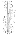
第1プレス体7及び第2プレス体8は、図1乃至図4に示すように、枢軸4bの軸心に沿って対向するとともに刃体2の長手方向に沿って互いに平行に延びる平坦な板状をなしている。尚、以下では、便宜上、一方の刃体2における第1プレス体7及び第2プレス体8を第1プレス体7A及び第2プレス体8Aと呼び、他方の刃体2における第1プレス体7及び第2プレス体8を第1プレス体7B及び第2プレス体8Bと呼ぶことにする。また、本発明における第1プレス体7及び第2プレス体8は、平坦な板状をなしているが、多少湾曲したり、或いは、略L字状の断面形状をなす部分が外周縁部の一部にあってもよい。
第1プレス体7Aは、枢軸4bの一端側に位置しており、図1に示すように、刃体2の基端側から順に、平面視で略三角形状をなす小指掛部7aと、使用者の薬指を挿入可能な薬指付根側指輪部7b(第1指輪部)と、外周縁部に人差し指及び中指を添えて操作する部分となるハンドル部7cと、該ハンドル部7cから中途部4側に向かって延びる延出部7dとを備え、薬指付根側指輪部7bは、小指掛部7a、ハンドル部7c及び延出部7dよりも側方に湾曲状に張り出した形状をなしている。
小指掛部7aには、略三角形状をなす開口部70aが形成され、ハンドル部7cには、略台形状をなす開口部70b、70cが刃体2の長手方向に沿うように並んで形成されている。
つまり、第1プレス体7Aの薬指付根側指輪部7bを除く領域には、それぞれ様々な形状をなす開口部70a~70cが形成されている。
薬指付根側指輪部7bは、理髪作業の際に薬指を挿入した状態で薬指の付根側に位置するようになっている。
第1プレス体7Aには、図5及び図6に示すように、4つのネジ挿通孔H1が形成されている。具体的には、4つのネジ挿通孔H1のうちの1つは小指掛部7aにおける薬指付根側指輪部7bの反対側に形成され、4つのネジ挿通孔H1のうちの2つは薬指付根側指輪部7bとハンドル部7cとが連続する部分に形成され、4つのネジ挿通孔H1のうちの1つはハンドル部7cと延出部7dとが連続する部分に形成されている。
延出部7dの中途部4側は、図4に示すように、切出部材6Aにおける取付面部6aに載置可能になっていて、該取付面部6aに延出部7dを載置した際、延出部7dの表面と切出部材6Aの表面とが面一になるようになっている。
延出部7dにおける中途部4側の縁部7hは、図7に示すように、切出部材6Aにおける取付面部6aの立壁部分6cの形状に対応するように緩やかに湾曲する凹状をなしている。
そして、延出部7dの中央には、図8に示すように、ネジ挿通孔H2が1つ形成されていて、延出部7dを切出部材6Aにおける取付面部6aに載置し、且つ、ネジ挿通孔H2とネジ挿通孔6bとにビスB1(締結部材)を挿通させるとともに当該ビスB1とナットN1とで延出部7dと切出部材6Aとを挟み込むことにより、切出部材6Aに延出部7dが接続されるようになっている。このように、延出部7dは、枢軸4bの軸心に沿って延びる姿勢のビスB1を用いて切出部材6Aに締結するので、締結する際に切出部材6Aに対する延出部7dのビスB1周りの角度の微調整が可能になる。したがって、一方の刃体2における中途部4と柄部5との間の細かな角度を使用者の好みに応じて変更したものにすることができる。
第2プレス体8Aは、枢軸4bの他端側に位置しており、図2に示すように、刃体2の基端側から順に、平面視で略三角形状をなす小指掛部8aと、使用者の薬指を挿入可能な薬指先端側指輪部8b(第2指輪部)と、外周縁部に人差し指及び中指を添えて操作する部分となるハンドル部8cとを備え、小指掛部8a、薬指先端側指輪部8b及びハンドル部8cは、小指掛部7a、薬指付根側指輪部7b及びハンドル部7cにそれぞれ対応する形状をなしている。
一方、第2プレス体8Aには、第1プレス体7Aの如き延出部7dが無く、切出部材6Aと離間している(図3参照)。
薬指先端側指輪部8bは、理髪作業の際に薬指を挿入した状態で薬指の先端側に位置するようになっている。
小指掛部8aには、小指掛部7aに形成された開口部70aに対応する形状の開口部80aが形成され、ハンドル部8cには、ハンドル部7cに形成された開口部70b、70cに対応する形状の開口部80b、80cが形成されている。
また、第2プレス体8Aにおける第1プレス体7Aの各ネジ挿通孔H1に対応する位置には、図5及び図6に示すように、ネジ挿通孔H3がそれぞれ形成されている。
第1プレス体7A及び第2プレス体8Aの間には、図1に示すように、刃体2の長手方向に沿って延びる略角棒状の第1樹脂体9A(橋絡部)が他方の刃体2側の縁部に沿うように設けられている。
すなわち、第1樹脂体9Aは、第1プレス体7A及び第2プレス体8Aを橋絡しており、第1プレス体7A及び第2プレス体8Aの間の一部領域を埋めるように設けられている。
第1樹脂体9Aの中途部には、他方の刃体2側に向かって突出する正面視で略三角形状をなす接点部9aが設けられ、該接点部9aは、第1樹脂体9Aを射出成形により成形する際に一体に形成されている。
また、第1樹脂体9Aにおけるネジ挿通孔H1、H3に対応する位置には、図5に示すように、ネジ挿通孔9bが形成され、ネジ挿通孔H1、ネジ挿通孔9b及びネジ挿通孔H3にビスB2を順に挿通させるとともに当該ビスB2とナットN2とで第1プレス体7A、第1樹脂体9A及び第2プレス体8Aを挟み込むことにより、当該第1プレス体7A、第1樹脂体9A及び第2プレス体8Aが一体になるようになっている。
一方、第1プレス体7A及び第2プレス体8Aにおける第1樹脂体9Aに対応しない領域において対向するネジ挿通孔H1、H3の間には、図6に示すように、ネジ挿通孔11aを有する円筒カラー11(橋絡部)が設けられ、ネジ挿通孔H1、ネジ挿通孔11a及びネジ挿通孔H3にビスB3を順に挿通させるとともに当該ビスB3とナットN3とで第1プレス体7A、円筒カラー11及び第2プレス体8Aを挟み込むことにより、当該第1プレス体7A、円筒カラー11及び第2プレス体8Aが一体になるようになっている。
尚、第1樹脂体9A、ビスB2及びナットN2は本発明の寸法変更部10aを構成する一方、円筒カラー11、ビスB3及びナットN3は本発明の寸法変更部10bを構成しており、第1樹脂体9A及び円筒カラー11の寸法を変更することによって一方の刃体2における柄部5の厚み方向の寸法を変更可能になっている。したがって、一方の刃体2における柄部5の厚み方向の寸法を使用者の好みに変更させることができるので、使い勝手の良い理髪用鋏1にすることができる。
第1プレス体7Bは、枢軸4bの他端側に位置しており、図2に示すように、刃体2の基端側から順に、使用者の親指を挿入可能な親指先端側指輪部7e(第1指輪部)と、正面視で略三角形状をなすハンドル部7fと、該ハンドル部7fから中途部4側に向かって延びる延出部7gとを備え、親指先端側指輪部7eは、ハンドル部7f及び延出部7gよりも側方に湾曲状に張り出した形状をなしている。
親指先端側指輪部7eは、理髪作業の際に親指を挿入した状態で親指の先端側に位置するようになっている。
ハンドル部7fには、略三角形状をなす開口部70dが形成されている。つまり、第1プレス体7Bの親指先端側指輪部7eを除く領域には、特徴的な形状の開口部70dが形成されている。
第1プレス体7Bには、図5及び図6に示すように、4つのネジ挿通孔H4が形成されている。具体的には、4つのネジ挿通孔H4のうちの1つは親指先端側指輪部7eにおけるハンドル部7fの反対側に形成され、4つのネジ挿通孔H4のうちの2つは親指先端側指輪部7eとハンドル部7fとが連続する部分に形成され、4つのネジ挿通孔H4のうちの1つは、ハンドル部7fと延出部7gとが連続する部分に形成されている。
延出部7gの中途部4側は、図4に示すように、切出部材6Bの取付面部6aに載置可能になっていて、該取付面部6aに延出部7gを載置した際、延出部7gの表面と切出部材6Bの表面とが面一になるようになっている。
延出部7gにおける中途部4側の縁部7jは、図2に示すように、切出部材6Bにおける取付面部6aの立壁部分6cの形状に対応するように緩やかに湾曲する凹状をなしている。
そして、延出部7gの中央には、図8に示すように、ネジ挿通孔H5が1つ形成されていて、延出部7gを切出部材6Bにおける取付面部6aに載置し、且つ、当該取付面部6aに形成されたネジ挿通孔6bとネジ挿通孔H5とにビスB4(締結部材)を挿通させるとともに当該ビスB4とナットN4とで切出部材6Bと延出部7gとを挟み込むことにより、当該切出部材6Bに延出部7gが接続されるようになっている。このように、延出部7gは、枢軸4bの軸心に沿って延びる姿勢のビスB4を用いて切出部材6Bに締結するので、締結する際に切出部材6Bに対する延出部7gのビスB4周りの角度の微調整が可能になる。したがって、他方の刃体2における中途部4と柄部5との間の細かな角度を使用者の好みに応じて変更したものにすることができる。
第2プレス体8Bは、枢軸4bの一端側に位置しており、図1に示すように、刃体2の基端側から順に、使用者の親指を挿入可能な親指付根側指輪部8e(第2指輪部)と、正面視で略三角形状をなすハンドル部8fとを備え、親指付根側指輪部8e及びハンドル部8fは、親指先端側指輪部7e及びハンドル部7fにそれぞれ対応する形状をなしている。
一方、第2プレス体8Bには、第1プレス体7Bの如き延出部7gが無く、切出部材6Bと離間している(図3参照)。
親指付根側指輪部8eは、理髪作業の際に親指を挿入した状態で親指の付け根側に位置するようになっていて、親指付根側指輪部8eにおける刃体2の長手方向に沿う方向の寸法D1は、親指先端側指輪部7eにおける刃体2の長手方向に沿う方向の寸法D2に比べて大きく設定されている。
ハンドル部8fには、略三角形状をなす開口部80dが形成されている。つまり、第2プレス体8Bの親指付根側指輪部8eを除く領域には、特徴的な形状の開口部80dが形成されている。
また、第2プレス体8Bにおける第1プレス体7Bの各ネジ挿通孔H4に対応する位置には、図5及び図6に示すように、ネジ挿通孔H6がそれぞれ形成されている。
第1プレス体7B及び第2プレス体8Bの間には、図1に示すように、刃体2の長手方向に沿って延びる略角棒状の第2樹脂体9B(橋絡部)が一方の刃体2側の縁部に沿うように設けられている。
すなわち、第2樹脂体9Bは、第1プレス体7B及び第2プレス体8Bを橋絡しており、第1プレス体7B及び第2プレス体8Bの間の一部領域を埋めるように設けられていて、両柄部5を接近させて両刃部3を閉じた際、上記接点部9aが接触してそれ以上の両刃体2の回動動作が阻止されるようになっている。
また、第2樹脂体9Bのネジ挿通孔H4、H6に対応する位置には、図5に示すように、ネジ挿通孔9cが形成され、ネジ挿通孔H6、ネジ挿通孔9c及びネジ挿通孔H4にビスB5を順に挿通させるとともに当該ビスB5とナットN5とで第1プレス体7B、第2樹脂体9B及び第2プレス体8Bを挟み込むことにより、当該第1プレス体7B、第2樹脂体9B及び第2プレス体8Bが一体になるようになっている。
一方、第1プレス体7B及び第2プレス体8Bにおける第2樹脂体9Bに対応しない領域において対向するネジ挿通孔H4、H6の間には、図6に示すように、ネジ挿通孔12aを有する円筒カラー12(橋絡部)が設けられ、ネジ挿通孔H6、ネジ挿通孔12a及びネジ挿通孔H4にビスB6を順に挿通させるとともに当該ビスB6とナットN6とで第1プレス体7B、円筒カラー12及び第2プレス体8Bを挟み込むことにより、当該第1プレス体7B、円筒カラー12及び第2プレス体8Bが一体になるようになっている。
尚、第2樹脂体9B、ビスB5及びナットN5は本発明の寸法変更部10cを構成する一方、円筒カラー12、ビスB6及びナットN6は本発明の寸法変更部10dを構成しており、第2樹脂体9B及び円筒カラー12の寸法を変更することによって他方の刃体2における柄部5の厚み方向の寸法を変更することができるようになっている。したがって、他方の刃体2における柄部5の厚み方向の寸法を使用者の好みに変更させることができるので、使い勝手の良い理髪用鋏1にすることができる。
また、第1樹脂体9A及び円筒カラー11は、第2樹脂体9B及び円筒カラー12よりも柄部5の厚み方向における寸法が大きく形成されている。したがって、ハンドル部7c、8cの外周縁部に使用者の人差し指及び中指を添えた際、ハンドル部7c、8cが各指に対して当該各指の延長方向に離間して接触するようになるので、使用者の理髪作業時における理髪用鋏1の開閉作業が安定するようになり、使い勝手の良い理髪用鋏1にすることができる。
以上より、本発明の実施形態1によると、理髪用鋏1を組み立てた際、各柄部5における第1プレス体7及び第2プレス体8の間の第1及び第2樹脂体9A、9B、及び、円筒カラー11、12を除く部分が構造物の無い空間になる。したがって、鋏1の柄部5側が軽量になり、理髪作業時に柄部5を動かす使用者の負荷を減らすことができる。
また、柄部5の表裏面を構成する部品が金属板によって形成されたものであるので、その表面を鏡面仕上げするとしても、柄部5を鋳造により形成する一般的な理髪用鋏1に比べて手間が掛からない。したがって、鋏1を製造する際の作業者の作業工数を減らすことができ、安価な理髪用鋏1にすることができる。
尚、一方の刃体2の中途部4における枢軸4bの一端側に第1プレス体7Aの延出部7dが接続される一方、他方の刃体2の中途部4における枢軸4bの他端側に第1プレス体7Bの延出部7gが接続され、さらには、両第2プレス体8A、8Bが各中途部4に接続されていないので、組み立てた理髪用鋏1の両柄部5を接近させた場合において、各第2プレス体8A、8Bが相手方の刃体2に接触して理髪用鋏1が閉じなくなるのを回避する構造になっている。
また、第1プレス体7及び第2プレス体8には、それぞれ様々な形状をなす複数の開口部70a~70d、80a~80dが形成されているので、各柄部5が複数のフレームを組み合わせて形成されたような見た目になり、鋏1全体の意匠性を高めることができる。
また、親指付根側指輪部8eは、対向する親指先端側指輪部7eに比べて大きな寸法に形成されているので、使用者が理髪作業を行う際、親指が親指付根側指輪部8eの範囲内において刃体2に対して親指先端側指輪部7eを回動支点に回動し易くなる。したがって、理髪作業時において鋏1を使用者の好みに合わせた姿勢に簡単に切り替えることができるようになる。特に、本発明の実施形態1では、親指付根側指輪部8eは、対向する親指先端側指輪部7eに比べて刃体2の長手方向に沿う方向に幅広な寸法に設定されているので、親指を刃体2の長手方向に揺らして鋏1に対する手の位置を変更する場合において鋏1の姿勢が切り替わり易くなり、理髪作業を効率良く行うことができるようになる。
また、第1及び第2樹脂体9A、9Bによって、第1プレス体7と第2プレス体8との間から第1及び第2樹脂体9A、9Bが見えるようになり、柄部5の意匠に変化が加わるので、鋏1の意匠性のさらに高めることができる。
また、両柄部5を接近させた際、両柄部5の互いに接触する部分(接点部9a及び第2樹脂体9B)が樹脂で形成されているので、接触時の衝撃を効率良く吸収することができる。
尚、本発明の実施形態1では、親指付根側指輪部8eが対向する親指先端側指輪部7eに比べて大きな寸法に形成されているが、親指先端側指輪部7eが親指付根側指輪部8eに比べて大きな寸法に形成された鋏1であってもよい。また、薬指先端側指輪部8bが対向する薬指付根側指輪部7bに比べて大きな寸法に形成された鋏1であってもよいし、薬指付根側指輪部7bが薬指先端側指輪部8bに比べて大きな寸法に形成された鋏1であってもよい。
また、本発明の実施形態1では、第1樹脂体9Aに接点部9aを設けているが、第2樹脂体9Bに第1樹脂体9A側に向かって突出する接点部9aを設けるようにしてもよい。
また、本発明の実施形態1では、接点部9aを第1樹脂体9Aの本体部分と一体成形により形成しているが、接点部9aを第1樹脂体9Aの本体部分とは別に形成して後から組み立てるようにしてもよい。
また、本発明の実施形態1では、切出部材6A、6Bに対して第1プレス体7A、7BをビスB1、B4による締結で接続しているが、接着剤やロウ付けによる接合で切出部材6A、6Bに第1プレス体7A、7Bを接続するようにしてもよい。
また、本発明の実施形態1では、第1樹脂体9A及び円筒カラー11における柄部5の厚み方向における寸法が第2樹脂体9B及び円筒カラー12よりも大きく形成されているが、第1樹脂体9A及び円筒カラー11における柄部5の厚み方向における寸法が第2樹脂体9B及び円筒カラー12と同じであってもよいし、小さく形成されていてもよい。
また、本発明の実施形態1では、柄部5の一部をプレス成形により形成した第1プレス体7及び第2プレス体8で構成しているが、当該第1プレス体7及び第2プレス体8を金属板から削り出した板状部材で構成するようにしてもよい。
《発明の実施形態2》
図9及び図10は、本発明の実施形態2に係る理髪用鋏1を示す。この実施形態2では、各柄部5の構造の一部が実施形態1と異なるだけでその他は実施形態1と同じであるため、以下、実施形態1と異なる部分のみを説明する。
図9及び図10は、本発明の実施形態2に係る理髪用鋏1を示す。この実施形態2では、各柄部5の構造の一部が実施形態1と異なるだけでその他は実施形態1と同じであるため、以下、実施形態1と異なる部分のみを説明する。
実施形態2の第1プレス体7A及び第2プレス体8Aの間、及び、第1プレス体7B及び第2プレス体8Bの間には、それぞれ第1樹脂体9A及び第2樹脂体9Bが設けられておらず、対応するネジ挿通孔H1、H3の間及びネジ挿通孔H4、H6の間は、全て円筒カラー11、12によって橋絡されている。
また、第2プレス体8Bの親指付根側指輪部8eにおける中途部4の反対側には、親指付根側指輪部8eの内側領域と外側領域とを連通させるとともに幅寸法D3が親指の幅寸法に対応する切欠部8iが形成されている。したがって、例えば、図10に示すように、使用者が人差し指を鋏1の先端側に向けて鋏1の中途部4に添えた状態にするとともに親指先端側指輪部7e及び親指付根側指輪部8eに対して親指を斜めの姿勢にした状態で鋏を持つような場合において、親指を切欠部8iに嵌め込むことができるようになる。それ故に、使用者は、上述の如き特殊な姿勢で鋏1を持つ場合であっても、親指に負荷を掛けることなく親指を柄部5にしっかりと引っ掛けて鋏1の開閉動作を行うことができる。
さらに、実施形態2の延出部7gには、枢軸4bの軸心に沿って一方の刃体2側に突出するピン7i(突出部)が形成され、該ピン7iは、両柄部5を接近させて両刃部3を閉じた際、延出部7dの縁部に接触してそれ以上の両刃体2の回動動作を阻止するようになっている。したがって、両柄部5を接近させた際、所定の位置で両刃体2の回動動作が止まるようになり、第1及び第2プレス体7、8の間に第1及び第2樹脂体9A、9Bを設けない実施形態1の如き構造の鋏1であっても必要な機能を有する鋏1にすることができる。
尚、本発明の実施形態2では、ピン7iが延出部7gに形成されているが、ピン7iを延出部7dに形成してもよく、両柄部5を接近させて両刃部3を閉じた際、延出部7gの縁部にピン7iを接触させてそれ以上の両刃体2の回動動作を阻止する構造であってもよい。
《発明の実施形態3》
図11は、本発明の実施形態3に係る理髪用鋏1を示す。この実施形態3では、第1プレス体7Bの一部構造が実施形態1と異なるだけでその他は実施形態1と同じであるため、以下、実施形態1と異なる部分のみを説明する。
図11は、本発明の実施形態3に係る理髪用鋏1を示す。この実施形態3では、第1プレス体7Bの一部構造が実施形態1と異なるだけでその他は実施形態1と同じであるため、以下、実施形態1と異なる部分のみを説明する。
実施形態3の第1プレス体7Bの延出部7gは、鋏1を把持した状態の使用者の掌から離れる方向に断面が鈍角なV字状となるように折り曲げられている。したがって、例えば、使用者が人差し指を鋏1の先端側に向けて鋏1の中途部4に添えた状態にするとともに親指先端側指輪部7e及び親指付根側指輪部8eに対して親指を斜めの姿勢にした状態で鋏1を持つような場合において、親指の延長方向に親指先端側指輪部7e及び親指付根側指輪部8eの貫通方向が沿うようになる。したがって、親指先端側指輪部7e及び親指付根側指輪部8eから親指に加わる負荷が少なくなり、使用者は、上述の如き特殊な姿勢で鋏1を持つ場合であっても、親指を柄部5にしっかりと引っ掛けて鋏1の開閉動作を簡単に行うことができる。
尚、本発明の実施形態3では、延出部7gを断面がV字状となるように折り曲げているが、これに限らず、例えば、延出部7gを撓みやすい素材の金属板で形成することによって、使用者が鋏1を把持した際に柄部5が使用者の掌から離れるように撓んで親指の延長方向に親指先端側指輪部7e及び親指付根側指輪部8eの貫通方向が沿うようになる構造にしてもよい。
《発明の実施形態4》
図12及び図13は、本発明の実施形態4に係る理髪用鋏1を示す。この実施形態4では、柄部5の一部構造が実施形態1と異なるだけでその他は実施形態1と同じであるため、以下、実施形態1と異なる部分のみを説明する。
図12及び図13は、本発明の実施形態4に係る理髪用鋏1を示す。この実施形態4では、柄部5の一部構造が実施形態1と異なるだけでその他は実施形態1と同じであるため、以下、実施形態1と異なる部分のみを説明する。
実施形態4では、実施形態1の第2プレス体8A及び第2プレス体8Bが樹脂材で形成された第2板状部8A及び第2板状部8Bになっており、実施形態1の如き第1樹脂体9A及び第2樹脂体9Bが設けられていない。
また、実施形態4では、実施形態1の如きネジ挿通孔H3、H6が形成されておらず、第2プレス体8A、8Bにおいてネジ挿通孔H3、H6が形成されていた部分には、ボス部80e、80fがそれぞれ突設されている。
また、第2板状部8A、8Bの外周縁部には、対応する第1板状部7A、7Bの外周縁部に向かって延出する外周壁部80g、80hが形成されている。
第2板状部8A、ボス部80e及び外周壁部80gは、射出成形により一体成形されている。
また、第2板状部8B、ボス部80f及び外周壁部80hも、射出成形により一体成形されている。
そして、ネジ挿通孔H1にビスB2、B3を挿通させるとともに当該ビスB2、B3をボス部80eに螺合させることにより、第1板状部7Aと第2板状部8Aとが一体になり、第1板状部7A、第2板状部8A及び外周壁部80gによって一方の柄部5に中空部5aが形成されるようになっている。
一方、ネジ挿通孔H4にビスB5、B6を挿通させるとともに当該ビスB5、B6をボス部80fに螺合させることにより、第1板状部7Bと第2板状部8Bとが一体になり、第1板状部7B、第2板状部8B及び外周壁部80hによって他方の柄部5に中空部5bが形成されるようになっている。
尚、実施形態4の寸法変更部10aは、ボス部80e及びビスB2で構成され、実施形態4の寸法変更部10bは、ボス部80e及びビスB3で構成され、実施形態4の寸法変更部10cは、ボス部80f及びビスB5で構成され、実施形態4の寸法変更部10dは、ボス部80f及びビスB6で構成されている。
以上より、本発明の実施形態4によると、柄部5の裏面を構成する部品が樹脂材で形成されたものであるので、その表面を鏡面仕上げする必要が無く、柄部5を鋳造により形成する一般的な理髪用鋏に比べて手間を掛けずに製造することができる。
尚、本発明の実施形態4では、第2板状部8A、8Bの外周縁部に外周壁部80g、80hを設けているが、当該外周壁部80g、80hを設けることは必須ではない。
また、本発明の実施形態4では、第2板状部8A、ボス部80e及び外周壁部80gを射出成形により一体成形するとともに、第2板状部8B、ボス部80f及び外周壁部80hを射出成形により一体成形しているが、それぞれ別々に形成した部品を接着剤等で一体にして完成させるような構造であってもよい。
《発明の実施形態5》
図14及び図15は、本発明の実施形態5に係る理髪用鋏1を示す。この実施形態5では、各柄部5の構造の一部が実施形態1と異なるだけでその他は実施形態1と同じであるため、以下、実施形態1と異なる部分のみを説明する。
図14及び図15は、本発明の実施形態5に係る理髪用鋏1を示す。この実施形態5では、各柄部5の構造の一部が実施形態1と異なるだけでその他は実施形態1と同じであるため、以下、実施形態1と異なる部分のみを説明する。
実施形態5の一方の刃体2における柄部5の第2プレス体8Aの中途部4側には、第1プレス体7A側に折り曲げられた第1折曲部8jが形成されている。
実施形態5の一方の刃体2における柄部5は、板状のアルミニウム合金材をプレス成形することにより得た第3プレス体13を備えている。
第3プレス体13は、第2プレス体8Aの表面側に所定の間隔をあけて平行に延びるよう配設された平坦な形状をなしていて、第3プレス体13と第2プレス体8Aとの間の間隔は、第2プレス体8Aと第1プレス体7Aとの間の間隔よりも狭く設定されている。
第3プレス体13は、刃体2の基端側から順に、平面視で略三角形状をなす小指掛部13aと、使用者の薬指を挿入可能な補助指輪部13b(第3指輪部)と、外周縁部に人差し指及び中指を添えて操作する部分となるハンドル部13cとを備え、小指掛部13a、補助指輪部13b及びハンドル部13cは、小指掛部8a、薬指先端側指輪部8b及びハンドル部8cにそれぞれ対応する形状をなしている。
小指掛部13aには、小指掛部8aに形成された開口部80aに対応する形状の開口部13fが形成され、ハンドル部13cには、ハンドル部8cに形成された開口部80b、80cに対応する形状の開口部13g、13hが形成されている。
第3プレス体13の小指掛部13aには、裏面側に開口する湾曲凹部13dが形成されている。
一方、第3プレス体13におけるハンドル部13cの中途部4側には、上記第1折曲部8jに対応するように第2プレス体8A側に折り曲げられた第2折曲部13eが形成されている。
第2プレス体8Aと第3プレス体13との間には、当該第2プレス体8Aと第3プレス体13とを連結するリング体15(連結部)が設けられている。
リング体15は、使用者の指が挿入可能に構成され、柔軟性を有するゴム材で形成されている。
リング体15は、薬指先端側指輪部8b及び補助指輪部13bの両方に嵌合することにより、第2プレス体8Aと第3プレス体13とを連結するようになっている。
実施形態5の第2プレス体8Aにおける小指掛部8aのビスB3は、小指掛部8aを貫通していて、その先端部分が小指掛部8aの表面から突出している。
ビスB3先端の小指掛部8aの表面から突出している部分は、本発明の突起14を構成しており、該突起14は、第3プレス体13の湾曲凹部13dに遊嵌している。
以上より、本発明の実施形態5によると、理髪用鋏1を操作する際に柄部5の外周縁部に人差し指及び中指を添えると、第1プレス体7A、第2プレス体8A及び第3プレス体13からなる3つの並設された板状部分が人差し指及び中指を所定の間隔で支えるとともに各板状部分により人差し指及び中指が柄部5の厚み方向にしっかりと引っ掛かるようになる。したがって、人差し指及び中指が柄部5の厚み方向に滑り難くなるとともに理髪用鋏1を保持し易くなるので、理髪用鋏1の操作性を高めることができる。
また、理髪用鋏1の重量配分が刃部3側よりも柄部5側の方が重くなり、使用者の手の方に理髪用鋏1の重心が位置するようになるので、刃部3側が軽くなって理髪用鋏1の操作性をさらに高めることができる。
また、理髪用鋏1を使用する際、柔軟性を有するリング体15の内方に指を挿入するので、理髪用鋏1の操作時における柄部5に対する指の触感を良くすることができる。
また、リング体15は柔軟性を有しているので、薬指先端側指輪部8b及び補助指輪部13bにリング体15を簡単に連結させることができ、しかも、薬指先端側指輪部8b及び補助指輪部13bとリング体とをしっかりと密着させることができる。
さらに、第3プレス体13は、柔軟性を有するリング体15を支点に第2プレス体8Aに対して傾動自在になる。したがって、理髪用鋏1を操作する際に使用者の手の動きに対応するように第3プレス体13が傾くようになり、操作性の良い理髪用鋏1にすることができる。
また、リング体15を使用して第3プレス体13を第2プレス体8Aに取り付けた際、湾曲凹部13dに突起14が入り込むので、第3プレス体13に対してリング体15の中心線周りの周方向に不意に力が加わっても第3プレス体13が第2プレス体8Aに対してリング体15の中心線周りの周方向に大きく回転してしまうのを防ぐことができる。
さらに、柄部5には、第1折曲部8j及び第2折曲部13eが形成されているので、使用者が理髪用鋏を使用する際に、使用者の指が第2プレス体8A及び第3プレス体13の第1プレス体7A側端部に引っ掛かり難くなり、理髪用鋏1の操作性をさらに高めることができる。
尚、本発明の実施形態5では、第3プレス体13が第2プレス体8Aの表面側に設けられているが、第1プレス体7Aの表面側に設ける構成であってもよい。この場合、補助指輪部13bは、第1プレス体7Aの薬指付根側指輪部7bに対応する位置に形成され、リング体15を薬指付根側指輪部7bと補助指輪部13bに嵌合して第1プレス体7Aと第3プレス体13とを連結する。また、突起14は、第1プレス体7Aの表面側に形成して、第3プレス体13の湾曲凹部13dに遊嵌させる。
また、本発明の実施形態5では、第3プレス体13が金属板で形成されているが、樹脂材から形成されたものであってもよい。
また、本発明の実施形態5では、第2プレス体8Aと第3プレス体13とをリング体15で連結しているが、これに限らず、例えば、実施形態1のように、ビス、ナット及び円筒カラーを用いて複数個所において第2プレス体8Aと第3プレス体13とを連結するようにしてもよい。
本発明は、理髪時に使用する理髪用鋏に適している。
1 理髪用鋏
2 刃体
3 刃部
4 中途部
4a 軸支孔
4b 枢軸
5 柄部
7、7A、7B 第1プレス体(第1板状部)
7b 薬指付根側指輪部(第1指輪部)
7d、7g 延出部
7e 親指先端側指輪部(第1指輪部)
7i ピン(突出部)
8、8A、8B 第2プレス体(第2板状部)
8b 薬指先端側指輪部(第2指輪部)
8e 親指付根側指輪部(第2指輪部)
8i 切欠部
8j 第1折曲部
9A 第1樹脂体(橋絡部)
9B 第2樹脂体(橋絡部)
9a 接点部
10a~10d 寸法変更部
11 円筒カラー(橋絡部)
12 円筒カラー(橋絡部)
13 第3プレス体(第3板状部)
13b 補助指輪部(第3指輪部)
13d 湾曲凹部
14 突起
15 リング体(連結部)
B1、B4 ビス(締結部材)
2 刃体
3 刃部
4 中途部
4a 軸支孔
4b 枢軸
5 柄部
7、7A、7B 第1プレス体(第1板状部)
7b 薬指付根側指輪部(第1指輪部)
7d、7g 延出部
7e 親指先端側指輪部(第1指輪部)
7i ピン(突出部)
8、8A、8B 第2プレス体(第2板状部)
8b 薬指先端側指輪部(第2指輪部)
8e 親指付根側指輪部(第2指輪部)
8i 切欠部
8j 第1折曲部
9A 第1樹脂体(橋絡部)
9B 第2樹脂体(橋絡部)
9a 接点部
10a~10d 寸法変更部
11 円筒カラー(橋絡部)
12 円筒カラー(橋絡部)
13 第3プレス体(第3板状部)
13b 補助指輪部(第3指輪部)
13d 湾曲凹部
14 突起
15 リング体(連結部)
B1、B4 ビス(締結部材)
Claims (16)
- 刃部、中途部及び柄部が先端側から順に形成された一対の刃体と、
該各刃体における中途部に設けられた軸支孔に順に嵌挿され、上記両柄部の接近離間動作によって上記両刃部が開閉するよう上記両刃体を互いに回動可能に連結する枢軸とを備えた理髪用鋏であって、
上記柄部は、上記枢軸の軸心に沿って対向するとともに上記刃体の長手方向に沿って互いに平行に延びる平坦な金属板又は樹脂材からなる第1及び第2板状部と、当該第1及び第2板状部を橋絡する1つ以上の橋絡部とを備え、
上記第1板状部は、上記第2板状部よりも対応する中途部側に延びて当該中途部に接続される延出部を有する一方、上記第2板状部は、対応する中途部と離間しており、
上記一方の柄部における第1板状部は、上記枢軸の一端側に位置する一方、上記一方の柄部における第2板状部は、上記枢軸の他端側に位置しており、
上記他方の柄部における第1板状部は、上記枢軸の他端側に位置する一方、上記他方の柄部における第2板状部は、上記枢軸の一端側に位置していることを特徴とする理髪用鋏。 - 請求項1に記載の理髪用鋏において、
上記第1板状部には、使用者の指を挿入可能な第1指輪部が形成され、
上記第2板状部の上記第1指輪部に対向する位置には、使用者の指を挿入可能な第2指輪部が形成され、
上記第1板状部の第1指輪部を除く領域及び上記第2板状部の第2指輪部を除く領域には、それぞれ様々な形状をなす複数の開口部が形成されていることを特徴とする理髪用鋏。 - 請求項2に記載の理髪用鋏において、
互いに対向する上記第1及び第2指輪部のいずれか一方は、理髪作業の際に親指を挿入した状態で親指の付け根側に位置する親指付根側指輪部であり、
互いに対向する上記第1及び第2指輪部のいずれか他方は、理髪作業の際に親指を挿入した状態で親指の先端側に位置する親指先端側指輪部であり、
上記親指付根側指輪部における上記中途部の反対側には、上記親指付根側指輪部の内側領域と外側領域とを連通させるよう切り欠かれた切欠部が設けられ、該切欠部の幅寸法が親指の幅寸法よりも大きく設定されていることを特徴とする理髪用鋏。 - 請求項2又は3に記載の理髪用鋏において、
互いに対向する上記第1及び第2指輪部のいずれか一方は、互いに対向する上記第1及び第2指輪部のいずれか他方に比べて大きな寸法に形成されていることを特徴とする理髪用鋏。 - 請求項4に記載の理髪用鋏において、
互いに対向する上記第1及び第2指輪部のいずれか一方は、互いに対向する上記第1及び第2指輪部のいずれか他方に比べて上記刃体の長手方向に沿う方向に幅広な寸法に設定されていることを特徴とする理髪用鋏。 - 請求項1から5のいずれか1つに記載の理髪用鋏において、
上記一方の延出部は、理髪作業時において親指に対応する側の柄部に設けられ、鋏を把持した状態の使用者の掌から離れる方向に断面が鈍角なV字状となるように折り曲げられていることを特徴とする理髪用鋏。 - 請求項1から6のいずれか1つに記載の理髪用鋏において、
上記橋絡部の少なくとも1つは、上記第1及び第2板状部の間の一部領域を埋める樹脂体であることを特徴とする理髪用鋏。 - 請求項7に記載の理髪用鋏において、
上記樹脂体は、上記両柄部における互いに接近する側の縁部に沿うように一対設けられ、一方の樹脂体には、他方の樹脂体に向かって突出するとともに、上記両柄部を接近させて上記両刃部を閉じた際、上記他方の樹脂体に接触してそれ以上の両刃体の回動動作を阻止する接点部が設けられていることを特徴とする理髪用鋏。 - 請求項1から7のいずれか1つに記載の理髪用鋏において、
上記一方の中途部における柄部側には、上記枢軸の軸心に沿って突出するとともに、上記両柄部を接近させて上記両刃部を閉じた際、上記他方の中途部における柄部側の縁部に接触してそれ以上の両刃体の回動動作を阻止する突出部が設けられていることを特徴とする理髪用鋏。 - 請求項1から9のいずれか1つに記載の理髪用鋏において、
上記延出部は、上記枢軸の軸心に沿って延びる姿勢の締結部材で上記中途部に締結されていることを特徴とする理髪用鋏。 - 請求項1から10のいずれか1つに記載の理髪用鋏において、
上記橋絡部の少なくとも1つは、上記柄部の厚み方向の寸法を変更可能な寸法変更部を有していることを特徴とする理髪用鋏。 - 請求項1から11のいずれか1つに記載の理髪用鋏において、
上記両柄部のいずれか一方は、理髪作業時において使用者の親指に対応しており、
上記両柄部のいずれか他方の全ての橋絡部は、上記両柄部のいずれか一方の全ての橋絡部よりも上記柄部の厚み方向における寸法が大きく形成されていることを特徴とする理髪用鋏。 - 請求項1から12のいずれか1つに記載の理髪用鋏において、
上記柄部は、上記第1板状部の表面側又は上記第2板状部の表面側に所定の間隔をあけて平行に延びるよう配設された平坦な金属板又は樹脂材からなる第3板状部と、上記第1及び第3板状部か、或いは、上記第2及び第3板状部を連結する1つ以上の連結部とを備えていることを特徴とする理髪用鋏。 - 請求項13に記載の理髪用鋏において、
上記第3板状部における上記第1指輪部又は上記第2指輪部に対応する位置には、使用者の指を挿入可能な第3指輪部が形成され、
上記連結部は、使用者の指が挿入可能に構成され、上記第1及び第3指輪部に嵌合可能か、或いは、上記第2及び第3指輪部に嵌合可能な柔軟性を有するリング体であることを特徴とする理髪用鋏。 - 請求項13又は14に記載の理髪用鋏において、
上記第3板状部には、裏面側に開口する湾曲凹部が形成され、
上記第1又は第2板状部の上記湾曲凹部に対応する位置には、当該湾曲凹部に遊嵌可能な突起が設けられていることを特徴とする理髪用鋏。 - 請求項1から15のいずれか1つに記載の理髪用鋏において、
上記第2板状部の上記中途部側には、上記第1板状部側に折り曲げられた折曲部が形成されていることを特徴とする理髪用鋏。
Priority Applications (4)
| Application Number | Priority Date | Filing Date | Title |
|---|---|---|---|
| JP2020501680A JP6764215B2 (ja) | 2018-02-20 | 2019-02-08 | 理髪用鋏 |
| EP19757143.3A EP3626414B1 (en) | 2018-02-20 | 2019-02-08 | Hairdressing scissors |
| CN201980007895.2A CN111587169B (zh) | 2018-02-20 | 2019-02-08 | 理发剪 |
| US16/709,855 US11148306B2 (en) | 2018-02-20 | 2019-12-10 | Hairdressing scissors |
Applications Claiming Priority (2)
| Application Number | Priority Date | Filing Date | Title |
|---|---|---|---|
| JP2018-027606 | 2018-02-20 | ||
| JP2018027606 | 2018-02-20 |
Related Child Applications (1)
| Application Number | Title | Priority Date | Filing Date |
|---|---|---|---|
| US16/709,855 Continuation US11148306B2 (en) | 2018-02-20 | 2019-12-10 | Hairdressing scissors |
Publications (1)
| Publication Number | Publication Date |
|---|---|
| WO2019163569A1 true WO2019163569A1 (ja) | 2019-08-29 |
Family
ID=67687091
Family Applications (1)
| Application Number | Title | Priority Date | Filing Date |
|---|---|---|---|
| PCT/JP2019/004666 Ceased WO2019163569A1 (ja) | 2018-02-20 | 2019-02-08 | 理髪用鋏 |
Country Status (5)
| Country | Link |
|---|---|
| US (1) | US11148306B2 (ja) |
| EP (1) | EP3626414B1 (ja) |
| JP (1) | JP6764215B2 (ja) |
| CN (1) | CN111587169B (ja) |
| WO (1) | WO2019163569A1 (ja) |
Cited By (1)
| Publication number | Priority date | Publication date | Assignee | Title |
|---|---|---|---|---|
| JP2024067845A (ja) * | 2022-11-07 | 2024-05-17 | 株式会社貝印刃物開発センター | 縫製用ハサミ |
Families Citing this family (2)
| Publication number | Priority date | Publication date | Assignee | Title |
|---|---|---|---|---|
| USD938246S1 (en) * | 2019-12-13 | 2021-12-14 | Mario Milinovic | Scissors |
| JP6916557B1 (ja) * | 2020-10-26 | 2021-08-11 | 足立工業株式会社 | 理美容鋏 |
Citations (6)
| Publication number | Priority date | Publication date | Assignee | Title |
|---|---|---|---|---|
| JPS50110491U (ja) * | 1974-02-16 | 1975-09-09 | ||
| JPH02119162U (ja) * | 1989-03-11 | 1990-09-26 | ||
| WO2002030632A1 (en) * | 2000-10-06 | 2002-04-18 | Adachi Kogyo, Inc. | Scissors with hole parts |
| JP2003038869A (ja) * | 2001-08-01 | 2003-02-12 | Adachi Kogyo:Kk | 指環と柄部が屈曲可能な鋏 |
| WO2006022368A1 (ja) | 2004-08-27 | 2006-03-02 | Kikuboshi Corporation | 鋏 |
| JP2013013382A (ja) * | 2011-07-06 | 2013-01-24 | Kishimoto Nokogu Seisakusho:Kk | 刈込鋏 |
Family Cites Families (8)
| Publication number | Priority date | Publication date | Assignee | Title |
|---|---|---|---|---|
| US3840990A (en) * | 1973-07-16 | 1974-10-15 | I Laurenti | Multi-thickness plastic handled scissors |
| GB1487192A (en) * | 1975-05-22 | 1977-09-28 | British Syphon Ind Ltd | Scissors |
| DE29609151U1 (de) * | 1996-03-07 | 1996-09-12 | ZWILLING J. A. Henckels AG, 42657 Solingen | Schere mit kunststoffumkleideten Augen |
| US6272754B1 (en) * | 1999-09-27 | 2001-08-14 | Jameson Corporation | Retrofit handle attachment for scissors |
| US7805842B2 (en) * | 2007-10-12 | 2010-10-05 | Bon Mots, Llc | Scissors with an integrated tape dispenser |
| CN202225226U (zh) * | 2011-09-08 | 2012-05-23 | 郑星杰 | 氧化锆陶瓷理发剪 |
| US20160368156A1 (en) * | 2015-06-16 | 2016-12-22 | Acme United Corporation | Scissors and Manufacturing Method Therefor |
| JP6776712B2 (ja) * | 2015-09-07 | 2020-10-28 | コクヨ株式会社 | カッター機能付きハサミ |
-
2019
- 2019-02-08 EP EP19757143.3A patent/EP3626414B1/en active Active
- 2019-02-08 CN CN201980007895.2A patent/CN111587169B/zh not_active Expired - Fee Related
- 2019-02-08 JP JP2020501680A patent/JP6764215B2/ja active Active
- 2019-02-08 WO PCT/JP2019/004666 patent/WO2019163569A1/ja not_active Ceased
- 2019-12-10 US US16/709,855 patent/US11148306B2/en not_active Expired - Fee Related
Patent Citations (6)
| Publication number | Priority date | Publication date | Assignee | Title |
|---|---|---|---|---|
| JPS50110491U (ja) * | 1974-02-16 | 1975-09-09 | ||
| JPH02119162U (ja) * | 1989-03-11 | 1990-09-26 | ||
| WO2002030632A1 (en) * | 2000-10-06 | 2002-04-18 | Adachi Kogyo, Inc. | Scissors with hole parts |
| JP2003038869A (ja) * | 2001-08-01 | 2003-02-12 | Adachi Kogyo:Kk | 指環と柄部が屈曲可能な鋏 |
| WO2006022368A1 (ja) | 2004-08-27 | 2006-03-02 | Kikuboshi Corporation | 鋏 |
| JP2013013382A (ja) * | 2011-07-06 | 2013-01-24 | Kishimoto Nokogu Seisakusho:Kk | 刈込鋏 |
Non-Patent Citations (1)
| Title |
|---|
| See also references of EP3626414A4 |
Cited By (1)
| Publication number | Priority date | Publication date | Assignee | Title |
|---|---|---|---|---|
| JP2024067845A (ja) * | 2022-11-07 | 2024-05-17 | 株式会社貝印刃物開発センター | 縫製用ハサミ |
Also Published As
| Publication number | Publication date |
|---|---|
| CN111587169A (zh) | 2020-08-25 |
| CN111587169B (zh) | 2022-03-29 |
| US20200130204A1 (en) | 2020-04-30 |
| JP6764215B2 (ja) | 2020-09-30 |
| EP3626414A4 (en) | 2021-03-17 |
| JPWO2019163569A1 (ja) | 2020-05-28 |
| EP3626414A1 (en) | 2020-03-25 |
| US11148306B2 (en) | 2021-10-19 |
| EP3626414B1 (en) | 2024-02-21 |
Similar Documents
| Publication | Publication Date | Title |
|---|---|---|
| US6493947B2 (en) | Scissors | |
| US20060123634A1 (en) | Scissors with handle opening overmold and ribbing | |
| WO2019163569A1 (ja) | 理髪用鋏 | |
| US12115691B2 (en) | Blade assembly attachment mechanism and modular razor assembly | |
| KR100513982B1 (ko) | 개구부를 갖는 가위 | |
| JP2007513732A (ja) | 中指ガイドを有する鋏 | |
| US6434833B1 (en) | Hairdressing scissor assembly | |
| JP2000127103A (ja) | 手 鋸 | |
| US6584693B2 (en) | Ergonomic handle for scissors | |
| US10478979B1 (en) | Shears useful for cutting hair | |
| EP0998864B1 (en) | Cutting device with two cutting blades having plastic applications on the handles | |
| JP4904453B2 (ja) | 美容用ピンセット | |
| JP2004073817A (ja) | 指間刈り用髪切りばさみ及び櫛 | |
| US11731298B1 (en) | Hair styling tool device | |
| JP2020130824A (ja) | ニッパー式爪切り | |
| JP2006346328A (ja) | 鋏 | |
| WO2002083375A1 (en) | Hair tool | |
| JP2025099908A (ja) | デリケートゾーン用ヘアカッター | |
| JP4662901B2 (ja) | 理美容鋏 | |
| US20070044318A1 (en) | Hairdressing scissors | |
| EP1892065B1 (en) | Hairdressing scissors with connecting device | |
| WO2002094512A1 (en) | The hair cutting scissors | |
| WO2009074967A1 (en) | Scissors | |
| US20050217689A1 (en) | Method and apparatus for trimming hair | |
| JPH1119341A (ja) | ハサミ |
Legal Events
| Date | Code | Title | Description |
|---|---|---|---|
| 121 | Ep: the epo has been informed by wipo that ep was designated in this application |
Ref document number: 19757143 Country of ref document: EP Kind code of ref document: A1 |
|
| ENP | Entry into the national phase |
Ref document number: 2020501680 Country of ref document: JP Kind code of ref document: A |
|
| ENP | Entry into the national phase |
Ref document number: 2019757143 Country of ref document: EP Effective date: 20191217 |
|
| NENP | Non-entry into the national phase |
Ref country code: DE |