WO2019163582A1 - サブフレーム構造 - Google Patents
サブフレーム構造 Download PDFInfo
- Publication number
- WO2019163582A1 WO2019163582A1 PCT/JP2019/004892 JP2019004892W WO2019163582A1 WO 2019163582 A1 WO2019163582 A1 WO 2019163582A1 JP 2019004892 W JP2019004892 W JP 2019004892W WO 2019163582 A1 WO2019163582 A1 WO 2019163582A1
- Authority
- WO
- WIPO (PCT)
- Prior art keywords
- vehicle body
- frame
- subframe
- vehicle
- width direction
- Prior art date
- Legal status (The legal status is an assumption and is not a legal conclusion. Google has not performed a legal analysis and makes no representation as to the accuracy of the status listed.)
- Ceased
Links
Images


Classifications
-
- B—PERFORMING OPERATIONS; TRANSPORTING
- B62—LAND VEHICLES FOR TRAVELLING OTHERWISE THAN ON RAILS
- B62D—MOTOR VEHICLES; TRAILERS
- B62D21/00—Understructures, i.e. chassis frame on which a vehicle body may be mounted
- B62D21/11—Understructures, i.e. chassis frame on which a vehicle body may be mounted with resilient means for suspension, e.g. of wheels or engine; sub-frames for mounting engine or suspensions
-
- B—PERFORMING OPERATIONS; TRANSPORTING
- B60—VEHICLES IN GENERAL
- B60R—VEHICLES, VEHICLE FITTINGS, OR VEHICLE PARTS, NOT OTHERWISE PROVIDED FOR
- B60R19/00—Wheel guards; Radiator guards, e.g. grilles; Obstruction removers; Fittings damping bouncing force in collisions
- B60R19/02—Bumpers, i.e. impact receiving or absorbing members for protecting vehicles or fending off blows from other vehicles or objects
- B60R19/04—Bumpers, i.e. impact receiving or absorbing members for protecting vehicles or fending off blows from other vehicles or objects formed from more than one section in a side-by-side arrangement
- B60R19/12—Bumpers, i.e. impact receiving or absorbing members for protecting vehicles or fending off blows from other vehicles or objects formed from more than one section in a side-by-side arrangement vertically spaced
-
- B—PERFORMING OPERATIONS; TRANSPORTING
- B62—LAND VEHICLES FOR TRAVELLING OTHERWISE THAN ON RAILS
- B62D—MOTOR VEHICLES; TRAILERS
- B62D21/00—Understructures, i.e. chassis frame on which a vehicle body may be mounted
-
- B—PERFORMING OPERATIONS; TRANSPORTING
- B62—LAND VEHICLES FOR TRAVELLING OTHERWISE THAN ON RAILS
- B62D—MOTOR VEHICLES; TRAILERS
- B62D21/00—Understructures, i.e. chassis frame on which a vehicle body may be mounted
- B62D21/02—Understructures, i.e. chassis frame on which a vehicle body may be mounted comprising longitudinally or transversely arranged frame members
- B62D21/03—Understructures, i.e. chassis frame on which a vehicle body may be mounted comprising longitudinally or transversely arranged frame members transverse members providing body support
-
- B—PERFORMING OPERATIONS; TRANSPORTING
- B62—LAND VEHICLES FOR TRAVELLING OTHERWISE THAN ON RAILS
- B62D—MOTOR VEHICLES; TRAILERS
- B62D21/00—Understructures, i.e. chassis frame on which a vehicle body may be mounted
- B62D21/15—Understructures, i.e. chassis frame on which a vehicle body may be mounted having impact absorbing means, e.g. a frame designed to permanently or temporarily change shape or dimension upon impact with another body
- B62D21/152—Front or rear frames
- B62D21/155—Sub-frames or underguards
-
- B—PERFORMING OPERATIONS; TRANSPORTING
- B62—LAND VEHICLES FOR TRAVELLING OTHERWISE THAN ON RAILS
- B62D—MOTOR VEHICLES; TRAILERS
- B62D29/00—Superstructures, understructures, or sub-units thereof, characterised by the material thereof
- B62D29/008—Superstructures, understructures, or sub-units thereof, characterised by the material thereof predominantly of light alloys, e.g. extruded
-
- B—PERFORMING OPERATIONS; TRANSPORTING
- B62—LAND VEHICLES FOR TRAVELLING OTHERWISE THAN ON RAILS
- B62D—MOTOR VEHICLES; TRAILERS
- B62D25/00—Superstructure or monocoque structure sub-units; Parts or details thereof not otherwise provided for
- B62D25/08—Front or rear portions
- B62D25/082—Engine compartments
Definitions
- the present invention relates to a subframe structure, and belongs to the technical field of the body structure of a vehicle such as an automobile.
- the front structure of the vehicle body is provided with a pair of left and right front side frames that extend in the front-rear direction of the vehicle to support the front of the vehicle body, and a subframe for supporting the power train is disposed below the front side frame. Is known.
- the vehicle body front part structure disclosed in Patent Document 1 has left and right side parts arranged below the front side frame, and a front side part that connects the front ends of the left and right side parts in the vehicle width direction. And a sub-frame formed in a U-shape by opening rearwardly, a tower member rising from the left and right side portions described above and connected to the lower surface of the front side frame, and an intermediate between the tower member in the vertical direction.
- a sub-frame structure that includes a pair of extension frames that extend forward from the position and deform in cooperation with the front side frame and absorb an impact during a frontal collision of the vehicle is employed.
- the subframe of Patent Document 1 has a function of supporting the power train through a mount support member fastened and fixed to the side portion. Furthermore, the tower member provided in the sub-frame is designed to branch and transmit the load input from the front of the vehicle via the extension frame to the left and right sides of the extension frame and the upper front side frame. It is composed. That is, the tower member has a function of urging the shock absorption by the extension frame while preventing the power train from retreating by reliably receiving the input load from the front of the vehicle body.
- Patent Document 1 achieves both a powertrain mount support function and an impact absorption function when an impact load is input from the front of the vehicle body by the above-described configuration.
- a load path for transmitting the input load input via the extension frame to the front side frame on the vehicle body side is not formed.
- the sub-frame is independently responsible for the function of promoting the impact absorption by the extension frame while preventing the power train from retreating against the input load when the impact load is input from the front of the vehicle body.
- the subframe has the powertrain mount support function that has been carried out until then, and Among the shock absorbing functions at the time of impact load input, the burden on the latter in particular becomes large, so a device is required to make both functions compatible.
- the above-described vibration is also attenuated on the path from the mount support portion to the vehicle body via the subframe. Measures are adopted. Specifically, for example, by providing a long vibration transmission path from the mount support portion to the vehicle body via the subframe, or by adding a damping member such as a rubber bush between the subframe and the vehicle body, The transmission of powertrain vibration to the vehicle body is suppressed.
- the vibration transmission path from the mount support portion to the vehicle body via the front portion of the subframe and the tower member, and the rear portion of the subframe from the mount support portion are arranged. Both of the vibration transmission paths to the vehicle body via the road are long.
- the present invention has been made in view of such problems, and achieves both the PT frame mounting function of the subframe and the shock absorbing function when inputting an impact load from the front of the vehicle body while reducing the vehicle weight and the number of parts.
- An object is to provide a subframe structure that more effectively reduces powertrain vibrations.
- the sub-frame has a main body portion extending in the front-rear direction of the vehicle body, and a mount support portion that supports the power train via the mount,
- the main body is fixed to the vehicle body structure via the mount support.
- body structure here refers to a portion constituting the skeleton of the vehicle body of the vehicle.
- the invention according to claim 2 is the invention according to claim 1,
- the mount support portion and the vehicle body structure are rigidly coupled without using a damping element.
- the invention according to claim 3 is the invention according to claim 1 or 2
- the mount support portion includes a housing portion that houses the mount from below while allowing connection with a bracket provided on the power train side, a vehicle body mounting portion that extends upward from the vicinity of the housing portion, and the housing And a reinforcing portion that is disposed between the vehicle body mounting portion and the vehicle body mounting portion and reinforces the space therebetween.
- the invention according to claim 4 is the invention according to claim 3,
- the reinforcing portion is a rib that connects between the vehicle body attachment portion and a lower portion of the housing portion than the vehicle body attachment portion.
- the invention according to claim 5 is the invention according to claim 3 or claim 4, wherein The vehicle body attachment portion is disposed adjacent to the housing portion in a bottom view.
- the invention according to claim 6 is the invention according to any one of claims 1 to 5, wherein
- the main body and the mount support are separate bodies,
- a cross member extending from the main body to the inner side in the vehicle body width direction is connected to the main body,
- the mount support part is fixed to the main body part and the cross member.
- the invention according to claim 7 is the invention according to claim 1 or claim 2, wherein A pair of left and right subframes are provided, Each of the sub-frames includes a link support portion that supports a suspension link, a rear vehicle body attachment portion that fixes the main body portion to the vehicle body structure on the vehicle body rear side of the link support portion, and the link support portion.
- the suspension link is configured to extend forward from the link support portion;
- the rotation axis of the suspension link is provided so as to intersect a line segment connecting the rear vehicle body attachment portion and the second vehicle body attachment portion.
- the invention according to claim 8 is the invention according to any one of claims 1 to 7,
- the vehicle body structure includes a front side frame that extends in the longitudinal direction of the vehicle body above the extension frame and the main body,
- the subframe is fixed to the front side frame.
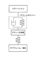
- the vibration of the power train that cannot be absorbed by the mount is transmitted from the mount support portion to the main body portion. It is transmitted to the car body without going through. That is, the vibration transmission path from the mount support part to the vehicle body can be formed shorter than the path from the mount support part to the vehicle body via the main body part of the subframe as in the conventional case. As a result, the entire path from the mount support part to the vehicle body can exhibit vibration characteristics close to a rigid body, which can effectively reduce the vibration of the powertrain by exhibiting the desired damping performance. it can.
- the vibration of the power train is input to the subframe and the vehicle body mainly through the mount rubber (hereinafter also referred to as mount rubber) and the mount support portion.
- mount rubber hereinafter also referred to as mount rubber
- the vibration input to the vehicle body depends on the spring constant of the mount rubber, the spring constant between the vehicle body and the mount support portion, and the damping element.
- the spring constant of the mount rubber can be optimized to reduce vibrations input from the powertrain to the vehicle body.
- the spring constant of the mount rubber is optimized in this manner, depending on the spring constant and the damping element between the vehicle body and the mount support portion, there is a possibility that the function does not function as expected.
- the entire path from the mount support portion to the vehicle body can exhibit vibration characteristics close to a rigid body, the spring constant between the vehicle body and the mount support portion can be improved. Since the damping element is eliminated as much as possible and the mount exhibits a desired damping performance, it is possible to effectively reduce the vibration of the power train.
- the mount support portion and the vehicle body structure are rigidly coupled without using a damping element such as a rubber bush, vibration transmission from the mount support portion to the vehicle body is achieved.
- the vibration characteristic in the path can be made closer to a rigid body. Therefore, unlike the conventional measure of adding a damping element other than the mount to the vibration transmission path from the mount support part to the vehicle body via the subframe, the mount can reliably exhibit the desired damping performance, Thereby, the vibration of a power train can be reduced more effectively.
- the support rigidity of the PT mount can be increased, and the rigidity between the housing portion, which is the vibration transmission path of the power train, and the vehicle body mounting portion is increased by the reinforcing portion.
- the spring constant from the housing portion to the vehicle body mounting portion is increased, and the mount can exhibit the desired damping performance.
- the transmission path for transmitting the vibration transmitted downward from the upper wall portion of the vibration of the power train input to the upper wall portion of the housing portion to the upper side again can be configured by a rib extending in the vertical direction.
- the periphery of the housing portion can be reinforced by the reinforcing portion and the vehicle body mounting portion against vibrations input from the power train to the PT mount.
- the mount support portion is fixed not only to the main body portion of the subframe but also to the cross member extending inward in the vehicle body width direction from the main body portion. It can be supported in a wide area in the vehicle body width direction. Thereby, in the case where the main body portion and the mount support portion are separate bodies, displacement that causes the mount support portion to fall inward in the vehicle body width direction is suppressed.
- the attachment portion of the sub frame to the vehicle body is provided at two places in the vehicle longitudinal direction including the rear vehicle body attachment portion and the second vehicle body attachment portion.
- the support rigidity of the subframe is increased.
- the sub frame is provided with a link support portion and the suspension link is configured to extend forward from the link support portion, a load in the front-rear direction is input to the support portion from the suspension link. .
- the pivot axis of the suspension link is provided so as to intersect the line connecting the rear vehicle body attachment portion and the second vehicle body attachment portion, for example, the vehicle body longitudinal direction is provided at the link support portion of the subframe.
- the load input from the front side of the vehicle body is transmitted from the front side frame to the rear side of the vehicle body, and from the extension frame to the subframe main body. It can be received in cooperation with the route that transmits to the car body.
- the impact on the vehicle interior side can be suppressed by reliably absorbing the impact load through these two paths.
- FIG. 4 is an enlarged sectional view taken along line Q1-Q1 in FIG. It is a perspective view which shows the sub-frame structure of 2nd Embodiment. It is a side view which shows the sub-frame structure of 2nd Embodiment. It is a top view which shows the sub-frame structure of 2nd Embodiment.
- FIG. 25 is a cross-sectional view taken along a line AA in FIG. 24, a cross-sectional view taken along a line BB, a cross-sectional view taken along a line CC, and a cross-sectional view taken along a line DD.
- It is the expanded bottom view of the junction part of a sub-frame, an extension frame, a 2nd cross member, and a front side bracket.
- It is a perspective view which expands and shows a powertrain mount and its peripheral part.
- arrow F indicates the front of the vehicle
- arrow R indicates the right side of the vehicle
- arrow L indicates the left side of the vehicle
- arrow U indicates the upper side of the vehicle
- arrow OUT indicates the outer side in the vehicle width direction
- arrow IN indicates the inner side in the vehicle width direction.
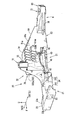
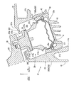
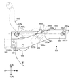
- FIGS. 1 to 3 show a front vehicle body structure including the subframe structure 10 of the first embodiment.
- a front vehicle body structure will be described mainly with reference to FIGS. 1 to 3 as a premise structure of the subframe structure 10 of the present embodiment.
- a front side frame 1 formed of a frame member as a strength member extending in the longitudinal direction of the vehicle body is provided on both left and right sides of the engine room E (see FIG. 3).
- the front side frame 1 constitutes a part of a vehicle body structure.
- a dash cross 5 extending in the vehicle width direction is connected to the rear part of the pair of left and right front side frames 1.
- the drive system is the front engine rear drive (FR), and as shown in FIG. 3, the engine room E between the front side frames 1 is connected to the vertically arranged engine 3 and the rear part thereof.
- a power train 2 having a transmission 4 is disposed.
- each front side frame 1 includes a front straight portion 1 a that linearly extends forward from the dash cross 5, an inclined portion 1 b that is rearwardly lowered from the dash cross 5 toward the rear of the vehicle body, A rear straight portion 1c that extends linearly further from the lower end of the inclined portion 1b and is connected to a floor frame (not shown) is provided. As shown in FIG. 2, each front side frame 1 has a rear straight portion 1c formed lower than the front straight portion 1a.
- a pair of left and right main crash cans 8 made of a cylindrical body or the like that absorbs shocks at the time of a collision are provided at the front end of each front side frame 1 via a set plate 6 and a mounting plate 7. Is provided.
- a bumper reinforcement 9 extending in the vehicle width direction is attached to the front end surfaces of the pair of left and right main crash cans 8.
- a sub-frame structure 10 that supports the lower arm 100 of the suspension device is disposed below each front side frame 1.
- the subframe structure 10 mainly includes a pair of left and right suspension subframes 20 (hereinafter also simply referred to as “subframes 20”), a pair of left and right extension frames 12, and a first frame. , Second front cross members 13 and 14 (see FIGS. 1 and 3) and a rear cross member 15 (see the same drawing).
- subcrash cans 19 extend forward from the left and right ends of the first front cross member 13 that extends in the vehicle width direction at the front end of the subframe structure 10. As shown in FIG. 3, the sub-crash can 19 is connected to both left and right ends of the first front cross member 13 via a set plate 18 and a mounting plate 17, respectively.
- a sub-bumper beam 11 is provided in front of the sub-crash can 19.
- the sub-bumper beam 11 is a so-called foot-wiping member that prevents a secondary collision by paying the pedestrian's legs and tilting the pedestrian on the hood when the vehicle collides with the pedestrian.
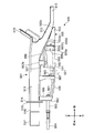
- the sub-frame 20 extends along the vehicle front-rear direction and is lower than the front side frame 1 from the intermediate position of the front straight portion 1 a in the vehicle front-rear direction to the inclined portion 1 b. As shown in FIG. 3, the front end of the subframe 20 is disposed forward of the front end of the engine 3. Details of the subframe 20 will be described later.
- the extension frame 12 is a frame member as a front impact load absorbing member that linearly extends forward from the front end portion of the sub-frame 20, and as shown in FIG. 2, the front portion of the front straight portion 1 a of the front side frame 1 It is arranged below.
- the first front cross member 13 extends linearly so as to bridge the front end portions of the pair of left and right extension frames 12 in the vehicle width direction.
- the left and right ends of the first front cross member 13 extending in the vehicle width direction are connected to the front end of the extension frame 12 and the rear end of the sub-crash can 19 via connecting members 16 on the left and right, respectively.
- the lower part of the connecting member 16 is connected to the extension frame 12 and is formed in a tower shape extending upward from the connecting part. Further, the connecting member 16 is formed in a hollow box shape, and the upper surface portion of the outer portion in the vehicle width direction is attached to the lower surface of the front side frame 1 via a mounting bush by a fastening member (not shown), A front vehicle body mounting portion 71 is configured.
- a set plate 18 is attached to the front face of the vertical wall shape of the connecting member 16 to join the rear face of the mounting plate 17 provided at the rear end of the sub-crash can 19 so that the sub-crash can 19 is attached. It is connected to the connection member 16 via the plate 17 and the set plate 18.
- the sub-frame 20 extending in the vehicle front-rear direction is a portion closer to the outer side in the vehicle width direction, and is not shown on the lower surface of the front side frame 1 in the middle and rear end portions in the vehicle front-rear direction.
- a vehicle body attachment portion an intermediate vehicle body attachment portion 72 and a rear vehicle body attachment portion 73 to be attached by a fastening member is provided (see FIGS. 1 to 3).
- the sub-frame structure 10 is attached to the front side frame 1 by the three locations of the intermediate vehicle body attachment portion 72, the rear vehicle body attachment portion 73, and the above-described front vehicle body attachment portion 71.
- the subframe 20 of the subframe structure 10 is attached to the front side frame 1 at two locations of an intermediate portion (intermediate vehicle body attachment portion 72) and a rear portion (rear vehicle body attachment portion 73) in the vehicle longitudinal direction.
- the vehicle body mounting portion that is attached to the lower surface of the front side frame 1 is not provided at the front portion of the sub frame 20 (see FIG. 2).
- the subframe 20 of the subframe structure 10 includes a support function for the lower arm 100 and a support function for the powertrain 2 described later, in addition to the vehicle body attachment portions 72 and 73 described above.
- the lower arm 100 is a suspension arm provided at a lower portion of a suspension device (not shown), and includes a front arm portion 101 extending substantially parallel to the vehicle width direction and a vehicle width direction of the front arm portion 101. And a rear arm portion 102 that extends substantially horizontally from the middle to the rear in the vehicle width direction and is formed in a substantially L shape in plan view.
- a front-side connecting portion 101a that is connected to the front side of the subframe 20 and a rear-side connecting portion 102a that is also connected to the rear side are formed at the vehicle width direction inner ends of the front and rear arm portions 101 and 102 in the vehicle width direction. (See FIGS. 1 to 3).
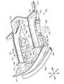
- the subframe structure 10 will be described with reference to FIGS. Since the pair of left and right subframe structures 10 have a bilaterally symmetric shape, the following description will be based on the left side configuration, unless otherwise specified.
- the main body portion 20 ⁇ / b> A of the subframe 20 of the suspension subframe structure 10 includes a front portion 21 to which the extension frame 12 and the second front crossmember 14 are connected, and a rear crossmember 15. Are connected to each other, and the intermediate portion 31 connecting the front portion 21 and the rear portion 61 is formed so as to extend in the longitudinal direction of the vehicle body as a whole.
- the subframe 20 is an aluminum block made of one member integrally formed by casting such as aluminum die casting. However, the subframe 20 may be made of a metal other than aluminum, such as iron.
- the front portion 21 has an insertion portion 22 into which the rear portion of the extension frame 12 (see FIGS. 1 to 4) is inserted toward the rear from the front end. It is formed in a concave shape. As shown in FIGS. 1 to 4, the extension frame 12 is integrally connected to the subframe 20 by inserting the rear portion thereof into the insertion portion 22.
- the front portion of the front portion 21 has an inner edge in the vehicle width direction extending inward in the vehicle width direction relative to the rear portion, and the second front cross member 14 extends in the vehicle width direction.
- a guide recess 23 is provided for fitting and connecting the outer end.
- the guide recess 23 has an upper wall portion 23a capable of fitting the second front cross member 14, a pair of guide side wall portions 23b and 23c extending downward from both front and rear ends of the upper wall portion 23a, and the vehicle width direction of the upper wall portion 23a.
- the vehicle width direction outer wall portion 23d extending downward from the outer end is formed into a concave shape that opens downward and inward in the vehicle width direction corresponding to the shape of the outer end portion of the second front cross member 14 in the vehicle width direction. (See FIG. 6 in particular).
- the second front cross member 14 is integrated with each of the wall portions 23a to 23c by welding or the like in a state where the outer end portion in the vehicle width direction is fitted in the guide recess 23. It is joined.
- the second front cross member 14 extends linearly between the front portions of the pair of left and right subframes 20 so as to bridge them in the vehicle width direction (see FIG. 3).
- the pair of front and rear guide side wall portions 23b and 23c are adjacent to the second front cross member 14 from the front and rear sides and extend in the vehicle width direction, and the front guide ribs guide the second front cross member 14 from the front and rear sides.
- the rear guide ribs are formed respectively. Accordingly, the second front cross member 14 is joined to the front portion 21 while being guided by the pair of front and rear guide side wall portions 23b and 23c.
- a front connecting portion 101a (see FIGS. 3 and 4) provided at the inner end in the vehicle width direction of the front arm portion 101 of the lower arm 100 is provided.
- a front side support portion 24 that is swingably supported is formed.
- the front support portion 24 is a pair of front and rear portions that are formed to protrude outwardly in the vehicle width direction with a flange in the vehicle front-rear direction outside the front portion 21 in the vehicle width direction.
- the pair of front and rear mounting portions 241 and 242 are respectively formed with bolt fastening holes 241a and 242a (see FIG. 8) penetrating in the vertical direction.
- the front side connecting portion 101 a of the lower arm 100 includes a shaft member 26 that extends through the elastic bush 25 embedded in the front side connecting portion 101 a and extends parallel to the vehicle longitudinal direction.
- the shaft member 26 is formed in a flat flange shape on both sides of the elastic bushing 25 in the axial direction so as to support the bolt head, and is installed on the upper surfaces of the mounting portions 241 and 242 on the front and rear sides, respectively.
- the bolts are fastened and fixed by bolts or the like at the bolt fastening holes 241a and 242a.
- the shaft member 26 extends in the vehicle front-rear direction so as to straddle the pair of front and rear mounting portions 241, 242, and the elastic bush 25 embedded in the front connection portion 101a can be swung by the shaft member 26. Is pivotally supported.
- the extension frame 12 is connected to the insertion portion 22 (see FIGS. 5 and 6) formed on the front surface of the subframe 20 on the outer side with respect to the intermediate position in the vehicle width direction.
- the front support portion 24 having high rigidity, for example, by including a fastening portion that fastens the front connection portion 101a of the lower arm 100.
- the sub-frame 20 enhances the shock absorbing function of the extension frame 12 at the time of a vehicle front collision.
- At least a front portion 21 of the sub-frame 20 in the vehicle front-rear direction is integrally formed with a front projecting portion 27 that projects inward in the vehicle width direction with respect to a base portion extending in the vehicle front-rear direction. Has been.
- the front projecting portion 27 is a second front cross member for the sub frame 20 when a force (lateral force) in the vehicle width direction is input from the lower arm 100 to the sub frame 20 of the sub frame structure 10 during traveling.
- 14 is configured as a displacement suppression means for suppressing the relative displacement of 14.
- a force (lateral force) in the vehicle width direction is input to the subframe 20 of the subframe structure 10 from the front wheel via the lower arm 100 during traveling of the vehicle, so that the pair of left and right subframes 20 There is a risk that a load (see arrow F1 in FIG. 3) that causes the distance between the vehicles in the vehicle width direction to narrow will act.
- the front portion of the subframe 20 of the subframe structure 10 is as described above.
- a configuration in which the vehicle body attachment portions (71, 72, 73) are not provided is employed (see FIGS. 2 and 3).
- the rigidity of the front portion of the subframe 20 tends to be lower than the configuration in which the vehicle body mounting portion is provided at the front portion of the subframe 20, so that the vehicle is traveling as described above.
- the front projecting portion 27 is provided at least in the front portion 21 of the subframe 20.
- the front projecting portion 27 includes a guide concave portion 23 to be joined in a state where the second front cross member 14 is fitted, and a guide concave portion 23 behind the guide concave portion 23. It is integrally formed with a reinforcing overhanging portion 271 that reinforces.
- the reinforcing overhanging portion 271 extends from the front to the rear edge of the guide recess 23 from a rear support portion 67 (see FIGS. 2 and 3), which will be described later, which supports the rear connecting portion 102a of the lower arm 100.
- the base portion of the sub-frame 20 (the center portion in the vehicle width direction extending in the vehicle front-rear direction) extends inward in the vehicle width direction.
- the reinforcing overhanging portion 271 of the present embodiment is formed in a range from the inner side wall of the intermediate portion 31 (accommodating portion 33 to be described later) to the rear edge of the guide recess 23 (FIGS. 4, 6, and FIG. 8). Further, the reinforcing overhanging portion 271 is integrally formed with the rear edge of the guide recess 23 so that the front end thereof is substantially the same as the guide recess 23 extending inward in the vehicle width direction. Further, it is formed in an inclined shape in plan view so that the length extending inward in the vehicle width direction is shortened.
- the intermediate portion 31 of the frame 20 forms a mount support portion 32 as a bulging portion whose substantially whole bulges upward from the front portion 21.
- An accommodation portion 33 is provided for accommodating the mount support structure 36 (PT mount 36) (see FIG. 12) connected to the PT side bracket 201 (see FIG. 12) provided on the side from below.
- the accommodating portion 33 includes an upper wall portion 331 that forms part of the mount support portion 32.
- a housing space 33 s opened downward by the side wall portion 332 is formed in a hollow shape.
- the mount support portion 32 extends horizontally from the outer edge in the vehicle width direction of the upper wall portion 331 of the housing portion 33 outward in the vehicle width direction.
- An intermediate overhang portion 34 is formed.
- the intermediate vehicle body mounting portion 72 is provided at a corner portion between the front edge and the vehicle width direction outer edge in a plan view of the intermediate overhang portion 34. It is erected in a columnar shape (cylindrical shape) so as to protrude upward.
- the intermediate vehicle body attachment portion 72 is rigidly coupled to the lower surface of the rear portion of the front linear portion 1a of the front side frame 1 by a bolt without using a damping element such as a rubber bush. Thereby, the rigidity between the intermediate vehicle body mounting portion 72 and the front side frame 1 is enhanced. Further, the intermediate vehicle body mounting portion 72 is disposed so as to have substantially the same height as the front vehicle body mounting portion 71 (see FIGS. 1 and 2).
- the front portion of the intermediate projecting portion 34 is formed with a raised portion 35 that protrudes upward with respect to its peripheral portion. Strictly speaking, the intermediate vehicle body mounting portion 72 is It is erected from the upper surface of the raised portion 35.
- the inner surface of the side wall portion 332 of the housing portion 33 (the surface facing the housing space 33s) is formed in an inclined shape in which the upper portion is inclined inward in the vehicle width direction with respect to the lower portion. Further, as shown in FIGS. 4, 10 (a), 10 (b), and 12, the upper wall portion 331 of the accommodating portion 33 is inclined so that the inner side in the vehicle width direction is positioned below the outer side in the vehicle width direction. Is formed.
- the PT mount 36 is accommodated in the accommodating portion 33 in an inclined posture in which the upper portion is inclined inward in the vehicle width direction with respect to the lower portion (see FIG. 12).
- the PT mount 36 is configured by a member 37 to be accommodated in the accommodating portion 33 and a hard core member 38 accommodated in the member 37.
- the accommodated member 37 includes a bowl-shaped outer shell portion 371 that is provided in the lower portion thereof and opens upward, and a mount rubber member 372 that is fitted into the outer shell portion 371 from above.
- the mount rubber member 372 has a trunk portion 372a, a shoulder portion 372b, and a neck portion 372c in this order from the bottom to the top, and is integrally formed in a stepped shape in a longitudinal sectional view by an elastic material such as rubber.
- the accommodated member 37 has an internal space corresponding to each diameter of the outer shell portion 371, the trunk portion 372a, the shoulder portion 372b, and the neck portion 372c, and is formed in a generally hollow truncated cone shape as a whole.
- the neck portion 372c protrudes upward with respect to the shoulder portion 372b, and the internal spaces 372s of the shoulder portion 372b and the neck portion 372c communicate with each other in the vertical direction. Furthermore, an opening 372d in which the internal space 372s opens upward is formed at the upper end of the neck 372c.
- the core member 38 is accommodated in the internal space 372s from the shoulder portion 372b to the neck portion 372c of the accommodated member 37, and the lower portion thereof is formed to have a larger diameter than the upper portion corresponding to the internal space of the shoulder portion 372b.
- the shoulder 372b is engaged with the upper wall of the internal space.
- the upper part of the core member 38 protrudes upward from the opening 372d.
- a PT bracket that is attached to a PT side bracket 201 (connected portion) that extends from the power train 2 side toward the outside in the vehicle width direction is provided on the upper portion of the core member 38.
- a mounting protruding piece 39 is provided.
- FIG. 3 only the PT mount 36 provided on the left side of the pair of left and right subframes is illustrated, and the PT mount 36 is not illustrated in drawings other than FIGS. 4, 3, and 12. .
- a neck portion insertion hole 372c1 through which a neck portion 372c provided in the member 37 accommodated in the accommodating portion 33 is inserted is formed through the center portion of the upper wall portion 331.
- the neck portion insertion hole 372 c 1 is formed with a smaller diameter than the shoulder portion 372 b provided in the member to be accommodated 37.
- the shoulder member 372b is engaged with the peripheral edge of the neck portion insertion hole 372c1, so that the member 37 to be accommodated does not come out from the accommodation space 33s of the accommodation portion 33 through the neck portion insertion hole 372c1.
- the projecting piece 39 for attaching the PT bracket provided on the core member 38 projects upward from the opening 372d of the neck portion 372c in a state in which the member 37 to be accommodated is accommodated in the accommodating portion 33, and is
- the PT mount 36 elastically supports the PT side bracket 201 from below by being connected by fastening with bolts or the like.
- the PT-side bracket 201 vibrates greatly during traveling of the vehicle, the PT mount 36 is elastically deformed and the rubber member 380 (buffer member) (see FIG. 12) provided on the upper surface of the upper wall portion 331 is used. By the upper wall portion 331, the PT-side bracket 201 is supported from the lower side (position regulation so as not to be further lowered).
- the PT-side bracket 201 can be supported with high support rigidity.
- the lower portion of the accommodating portion 33 is opened slightly outward in the vehicle width direction with respect to the vertically downward direction.
- the accommodating portion 33 is not formed until the lower end position Pd (bottom surface portion) (see FIG. 12) of the subframe 20 is reached.
- Pd bottom surface portion
- FIG. 9 (b) An opening 33a (see FIG. 9B) located at the lower end of the accommodating portion 33 is formed at a position higher than the bottom surface.
- the subframe structure 10 further includes a holding member 40 for holding the PT mount 36 accommodated in the accommodating portion 33 from below.
- the holding member 40 includes a disc-shaped bottom wall portion 41 that closes the opening 33 a of the housing portion 33, and the bottom wall.
- a side wall portion 42 that rises upward from the outer peripheral edge of the portion 41, and flange portions 43 and 44 (see FIG. 7) that protrude forward and rearward from the front and rear sides and are formed with bolt insertion holes 43a and 44a. It is integrally formed by casting such as aluminum die casting.
- the bottom wall portion 41 is provided with a plurality of ribs 45 that protrude downward from the lower surface portion (bottom surface portion) and extend in the vehicle width direction with an interval in the vehicle front-rear direction.
- the mounting seat surfaces 30 a and 30 b for mounting the holding member 40 are formed on the front and rear edges of the periphery of the opening 33 a, and the mounting seat surfaces 30 a and 30 b on the front and rear sides are formed. Is formed flat at a level higher than the bottom surface of the subframe 20 (see FIG. 9B), and bolt insertion holes 30aa and 30bb are formed respectively.
- the holding member 40 is fastened and fixed by bolts from below to the mounting seat surfaces 30a and 30b corresponding to the front and rear flange portions 43 and 44, respectively (see FIG. 7).
- the to-be-accepted member 37 in the state of being accommodated in the opening portion 33a is closed so as not to drop out of the opening portion 33a (see FIGS. 11A and 11B).
- the holding member 40 holds the PT mount 36 from the lower side at a position higher than the bottom surface portion of the subframe 20 (see the bottom surface position Pd in FIG. 12). .
- the holding member 40 has a mounting height in which at least a part of the holding member 40 is included in the range of the thickness t in the vertical direction of the extension frame 12 extending forward.
- the extension frame 12 is attached to the accommodating portion 33 of the subframe 20 at an attachment height that overlaps the extension frame 12 in the vertical direction.
- an engagement recess 40 a is formed on the inner peripheral surface of the side wall portion 42 of the holding member 40, and the outer peripheral surface of the outer shell portion 371 provided at the lower portion of the PT mount 36 is An engagement convex portion 37a is formed.
- the PT mount 36 is accommodated in the accommodating portion 33 in a state where the engaging convex portion 37a is engaged with the engaging concave portion 40a and is installed on the upper surface of the bottom wall portion 41 of the holding member 40 (see FIG. 12). ).
- the side wall portion 332 a (the vehicle width inner side wall portion 332 a) located on the inner side in the vehicle width direction is
- the outer peripheral surface of the cylindrical body is formed so as to constitute a part of the substantially cylindrical outer peripheral surface extending in the vertical direction by protruding inward in the vehicle width direction with respect to the vehicle width outer edge 331a (see FIG. 4) of the upper wall portion 331.
- the upper surface of the side wall 332 of the housing portion 33 is formed in an inclined shape in which the upper portion is inclined inward in the vehicle width direction with respect to the lower portion.
- Side wall portions 332b vehicle width outer wall portions 332b located on the outer side in the vehicle width direction with respect to the vehicle width outer edge 331a of the wall portion 331 (see FIG. 4A) are shown in FIGS. 5 to 7 and FIG. (B) As shown in FIG. 12, it forms so that the lower part may protrude toward the vehicle width direction outer side with respect to the upper part.
- a plurality of reinforcing members 33 and 72 are provided between the accommodating portion 33 and the intermediate vehicle body mounting portion 72. Reinforcing ribs 51a and 51b are provided.
- the reinforcing rib 51 a extending in the vertical direction is a lower surface of the intermediate overhanging portion 34 positioned at the base end of the intermediate vehicle body mounting portion 72 and a vehicle width positioned below the intermediate vehicle body mounting portion 72. While being formed in a straight line in the vertical direction so as to connect to the outer surface of the outer side wall portion 332b, a plurality are arranged at intervals in the vehicle front-rear direction (see FIG. 5).
- the reinforcing rib 51a extending in the vertical direction is formed such that the protruding length outward in the vehicle width direction gradually increases upward with respect to the vehicle width outer wall portion 332b of the housing portion 33.
- the upper end portion extends in the vehicle width direction until it reaches the outer end in the vehicle width direction of the intermediate overhang portion 34.
- reinforcing ribs 51b extending substantially horizontally in the vehicle front-rear direction so as to cross the reinforcing ribs 51a are formed in the intermediate portions in the vertical direction of the plurality of reinforcing ribs 51a extending in the vertical direction.
- the plurality of reinforcing ribs 51a extending in the vertical direction are connected to each other by the reinforcing ribs 51b extending in the vertical direction.
- the plurality of reinforcing ribs 51 a and 51 b and the intermediate vehicle body mounting portion 72 described above are both on the outer side in the vehicle width direction with respect to the housing portion 33 (opening portion 33 a) in the bottom view of the subframe 20. Adjacent to each other.
- the rear portion 61 of the subframe 20 includes a rear portion front side 62 extending substantially linearly along the vehicle front-rear direction and a rear end of the rear portion front side 62 with respect to the vehicle front-rear direction.
- the rear portion 63 is formed integrally with a rear portion rear side 63 that is inclined outwardly in the vehicle width direction and extends substantially linearly.
- the rear portion 61 of the subframe 20 has a vertical wall portion 64 that rises upward with respect to the upper surface of the base portion of the rear portion 61. Is formed.
- the vertical wall portion 64 extends in the vehicle front-rear direction from the front end to the front portion of the rear portion rear side 63 at the outer edge portion in the vehicle width direction of the rear portion front side 62 of the rear portion 61 and gradually decreases rearward. Thus, it is formed in an inclined shape in a side view.
- the front end of the vertical wall portion 64 is formed integrally with the housing portion 33 so as to continuously extend rearward from the rear end of the side wall portion 332 of the housing portion 33, and with the upper wall portion 331 of the housing portion 33. It is formed at the same height. Moreover, the upper end part of the vertical wall part 64 is formed with a flange part 64a that protrudes inward in the vehicle width direction from the front end to the intermediate part in the vehicle longitudinal direction. As shown in FIG. 4, FIG. 9A, and FIG. 10A, the corner portion between the inner surface in the vehicle width direction of the vertical wall portion 64 and the upper surface of the base portion on the front side 62 of the rear portion is connected between them. A plurality of reinforcing ribs 65 are erected at intervals in the vehicle front-rear direction.
- FIG. 9 (a), and FIG. 10 (a) the corner portion (inner corner portion in plan view) on the outer side in the vehicle width direction of the rear portion front side 62 and the rear portion rear side 63 is shown.
- a rear projecting portion 66 extending outward in the vehicle width direction is formed.
- the rear projecting portion 66 has a rear end extending rearward along the rear portion rear side 63 to the rear portion of the rear portion 61 of the subframe 20.
- a rear connecting portion 102a (see FIG. 2) provided at the inner end in the vehicle width direction of the rear arm portion 102 of the lower arm 100 is swingable.
- a rear support 67 for supporting is formed. Specifically, as shown in FIGS. 1 to 3, the rear support portion 67 includes a lower arm rear support bracket 67A.
- the lower arm rear support bracket 67A is provided with mounting flange portions 67a and 67b attached to the subframe 20 of the subframe structure 10 on each of the front and rear sides thereof.
- the front mounting flange portion 67a is bolted to a bolt fastening hole 67aa (see FIGS. 5, 7, and 9A) formed on the outer wall surface of the vertical wall portion 64 in the vehicle width direction.
- the rear attachment flange portion 67b is fastened and fixed to a bolt fastening hole 67bb (see FIGS. 6 and 8) formed in the rear overhang portion 66 via a bolt.
- the rear connecting portion 102a of the lower arm 100 is inserted into an elastic bush 69 (see FIG. 4) provided inside the lower arm rear supporting bracket 67A so that the shaft member 68 extending rearward is inserted into the rear supporting portion 67. It is pivotally supported.
- the front side connecting portion 101a and the rear side connecting portion 102a of the lower arm 100 are arranged in parallel and coaxially in the vehicle longitudinal direction.
- the rear body attachment is fastened and fixed to the lower surface of the front side frame 1 via the mount bushing on the upper surface portion of the rear portion rear side 63.
- a portion 73 is formed.
- the rear vehicle body mounting portion 73 has a bolt insertion hole 73 a at a position corresponding to the front portion of the rear straight portion 1 c of the front side frame 1 on the rear rear portion 63 in plan view. It is formed in a seat surface shape, and is formed at a height lower than the front vehicle body attachment portion 71 and the intermediate vehicle body attachment portion 72 so that it can be attached to the lower surface of the front portion of the rear straight portion 1c. (See FIG. 2).
- the intermediate vehicle body attachment portion 72, the rear vehicle body attachment portion 73, and the front vehicle body attachment portion 71 are disposed along the vehicle front-rear direction so as to substantially coincide with each other in the vehicle width direction.
- the subframe structure 10 is connected to the front side frame 1 via the vehicle body attachment portions 71, 72, and 73.
- the subframe structure 10 of the present embodiment is located at the front end position of the subframe 20 of the subframe structure 10 corresponding to a substantially intermediate position between the front vehicle body attachment portion 71 and the intermediate vehicle body attachment portion 72.
- a configuration in which the vehicle body mounting portion is attached to the front side frame 1 by three vehicle body mounting portions 71, 72, 73 without employing the vehicle body mounting portion is adopted.
- the vehicle body attachment portion prevents the extension frame 12 from being crushed to the rear end at the time of a front collision, as in the case where the vehicle body attachment portion is provided at the front end position of the subframe 20 of the subframe structure 10. There is no fear, and it can be promoted that the extension frame 12 is crushed to the rear end.
- the rear side of the rear part front side 62 of the rear part 61 (in other words, the front part of the rear part rear side 63)
- a guide recess 74 is provided for fitting and connecting the outer end of the side cross member 15 in the vehicle width direction.
- the guide recess 74 has an upper wall portion 74a, a pair of guide side wall portions 74b and 74c that extend downward from both front and rear ends of the upper wall portion 74a so that the rear cross member 15 can be fitted, and an outer side in the vehicle width direction of the upper wall portion 74a.
- the vehicle width direction outer wall portion 74d extending downward from the end is formed in a concave shape that opens downward and inward in the vehicle width direction corresponding to the shape of the outer end portion of the rear cross member 15 in the vehicle width direction.
- the rear cross member 15 is integrally joined to the upper wall portion 74a by being fastened while being fitted in the guide recess 74. Accordingly, the rear cross member 15 extends linearly between the rear portions of the pair of left and right subframes 20 so as to bridge them in the vehicle width direction.
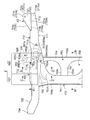
- a plurality of reinforcing ribs 81 to 88 projecting downward from the bottom surface portion are formed on the bottom surface portion of the sub frame 20 of the sub frame structure 10. ing.
- the plurality of reinforcing ribs 81 to 88 will be described with reference to FIG. 6, FIG. 8, FIG. 9 (b), and FIG.
- the front portion of the base portion of the subframe 20 in the vehicle width direction inside and outside both ends (substantially middle portion of the front portion 21 in the vehicle front-rear direction).
- a vehicle width inner edge rib 81 and a vehicle width outer edge rib 82 extending substantially parallel to each other and substantially parallel to each other in the vehicle front-rear direction from the rear portion to the rear portion (rear end of the rear portion 61) are formed.
- the vehicle width inner edge rib 81 is formed by bulging a portion corresponding to the housing portion 33 in the vehicle front-rear direction in an arc shape inward in the vehicle width direction so as to bypass the housing portion 33 in a bottom view (see FIG. 6, see FIG. Further, the vehicle width inner edge rib 81 forms a portion corresponding to the front wall guide portion 74b of the guide recess 74 for connecting the rear cross member 15 in the vehicle front-rear direction by the front wall guide portion 74b. On the other hand, the vehicle width outer edge rib 82 is formed along the vehicle front-rear direction across the intermediate portion 31 so as to be interrupted at the intermediate portion 31.
- the front portion 21 has a pair of guide wall reinforcing ribs 83 extending forward from the front end of the vehicle width inner edge rib 81 so as to branch into a bifurcated shape in the vehicle width direction when viewed from the bottom. 84 is formed.
- the pair of guide wall reinforcing ribs 83, 84 are both formed along the vehicle width direction.
- the guide wall reinforcing rib 83 (guide wall first reinforcing rib 83 on the inner side in the vehicle width direction). ) Is formed in the front overhanging portion 27 (reinforcement overhanging portion 271).
- the guide wall first reinforcing rib 83 is located in the vehicle width direction of the rear guide wall 23 c in the guide recess 23 for connection of the second front cross member 14.
- the guide wall reinforcing rib 84 (guide second wall reinforcing rib 84) on the outer side in the vehicle width direction is connected to the outer end in the vehicle width direction of the guide wall 23c on the rear side of the guide recess 23.
- the front portion 21 is linearly formed along the vehicle width direction so as to connect between the vehicle width outer edge rib 82 and the vehicle width inner edge rib 81.
- Extending first to third bottom front reinforcing ribs 85a, 85b, 85c are arranged in this order in the vehicle longitudinal direction.
- the first to third bottom front reinforcing ribs 85 a, 85 b and 85 c are formed on the rear mounting portion 242 of the pair of front and rear mounting portions 241 and 242 constituting the front support portion 24.
- it is formed in the inner peripheral portion in the vehicle width direction, and rearward in a bottom view so that the distance in the vehicle front-rear direction between adjacent ones gradually increases from the vehicle width outer edge rib 82 toward the vehicle width inner edge rib 81.
- the mounting portion 242 extends radially.
- a load (lateral force) in the vehicle width direction that is input from the front wheel to the front support portion 24 via the lower arm 100 during traveling is applied to the front portion 21. It is configured to be efficiently distributed throughout.
- the reinforcing overhanging portion 271 of the front overhanging portion 27 includes a vehicle width direction inner edge reinforcing rib 86 a extending along the vehicle width direction inner edge, and is spaced apart in the vehicle longitudinal direction.
- First to third front projecting portion reinforcing ribs 86b to 86d extending along the width direction are formed.
- the lower part of the vehicle width inner side wall portion 332 a of the accommodating portion 33 included in the intermediate portion 31 of the subframe structure 10 is on each side in the vehicle width direction in a cross-sectional view orthogonal to the vehicle longitudinal direction.
- the bifurcated portion on the inner side in the vehicle width direction is formed by a vehicle width inner edge rib 81.
- the intermediate portion 31 of the subframe structure 10 has first and second bottom surface intermediate ribs connecting the bifurcated lower portion of the vehicle width inner side wall portion 332 a of the accommodating portion 33.
- 87a and 87b are formed along the vehicle width direction.
- the rear portion 61 has first to seventh bottom rear ribs 88a to 88f connecting the vehicle width inner edge rib 81 and the vehicle width outer edge rib 82 along the vehicle width direction. Is formed.
- the second to sixth bottom surface rear ribs 88b to 88e are applied to the moment load input from the lower arm 100 to the rear support portion 67 around the front support portion 24.
- the rear portion 61 is provided at the inner peripheral portion as a reinforcing portion that reinforces the inner peripheral portion in the vehicle width direction with respect to the rear support portion 67.
- a moment load M centered on the front support portion 24 in plan view is transmitted via the rear support portion 67 to the subframe structure. 10 subframes 20 (see arrow M in FIG. 8).
- Such a moment load is applied to the subframe 20 of the subframe structure 10 from the lower arm 100 via the rear support portion 67 depending on the longitudinal force applied to the front wheels not only during the frontal collision of the vehicle but also during traveling. There is a fear.
- the second to sixth bottom rear ribs 88b to 88e with respect to the moment load that is input from the lower arm 100 to the rear support portion 67 and that is centered on the front support portion 24 described above. are formed radially around the rear support 67 in a bottom view.
- the second and third bottom rear ribs 88b and 88c extend linearly forward and inward in the vehicle width direction with respect to the rear support portion 67
- the sixth bottom rear ribs 88d, 88e, 88f extend linearly rearward and inward in the vehicle width direction with respect to the rear support portion 67.
- the vehicle width inner edge rib 81, the vehicle width outer edge rib 82, and the second and third bottom rear ribs 88b and 88c that are connected in the vehicle width direction and are adjacent to each other in the vehicle width direction are substantially trussed in bottom view. It is formed in a shape Tb.
- the vehicle width inner edge rib 81, the vehicle width outer edge rib 82, and the third and fourth bottom rear ribs 88c, 88d that are connected in the vehicle width direction and are adjacent to each other in the vehicle width direction, have a substantially truss shape Tc in a bottom view. Is formed.
- the vehicle width inner edge rib 81, the vehicle width outer edge rib 82, and the fourth and fifth bottom rear ribs 88d and 88e which are connected in the vehicle width direction and are adjacent in the vehicle width direction, are substantially truss-shaped in bottom view. It is formed at Td.
- the above-described subframe structure 10 of the present embodiment includes a subframe 20 that supports the power train 2 via a PT mount 36 (see FIG. 12), and the subframe 20. And an extension frame 12 that extends forward from the front and absorbs a collision load from the front of the vehicle.
- the sub-frame structure 10 is attached to the lower side with respect to the front side frame 1 (see FIGS. 1 and 2) extending in the vehicle front-rear direction at the front of the vehicle body.
- the subframe 20 is provided with a receiving portion 33 for receiving the PT mount 36 in a receiving space 33 s provided therein from below while allowing connection with a PT-side bracket 201 (see FIG. 12) provided with the PT mount 36 on the power train 2 side.
- a vehicle body attachment portion extending upward from the vicinity of the accommodation portion 33 is provided, and the accommodation portion 33 and the intermediate vehicle body attachment portion 72 (vehicle body) are provided.
- Reinforcing ribs 51a and 51b as reinforcing portions for reinforcing the space between them are provided (see FIGS. 4, 5, and 7).
- the PT mount 36 can be supported by the entire subframe 20 (at a position closer to the center of gravity of the accommodating portion 33 of the subframe 20) by accommodating the PT mount 36 in the accommodating portion 33.
- the support rigidity of the power train 2 can be increased.
- the intermediate vehicle body mounting portion 72 is configured to extend upward from the vicinity of the accommodating portion 33, the front side frame 1 has vibration of the power train 2 via the intermediate vehicle body mounting portion 72 (having a portion far from the position of the passenger's ear). Can be transmitted to and absorbed by the front linear portion 1a. At that time, vibrations can be efficiently transmitted from the housing portion 33 to the intermediate vehicle body attachment portion 72 by the reinforcing ribs 51a and 51b.
- the reinforcing portion includes a reinforcing rib 51a extending in the vertical direction so as to connect the intermediate vehicle body attaching portion 72 and the lower portion of the accommodating portion 33 with respect to the intermediate vehicle body attaching portion 72. Ribs) (see the figure).
- the transmission path for transmitting the vibrations transmitted downward below the upper wall portion 331 again to the upper direction It can be constituted by a reinforcing rib 51a extending in the direction. Therefore, the vibration transmitted downward from the upper wall portion 331 in the housing portion 33 can be efficiently transmitted to the intermediate vehicle body attachment portion 72 extending upward from the vicinity of the housing portion 33 by the reinforcing rib 51a.
- the reinforcing ribs 51a and 51b and the intermediate vehicle body mounting portion 72 are disposed adjacent to the housing portion 33 in a bottom view (see FIG. 8).
- the periphery of the housing portion 33 can be reinforced by vibrations input from the power train 2 to the PT mount 36 by the reinforcing ribs 51a and 51b and the intermediate vehicle body attachment portion 72.
- the rigidity of the upper wall portion 331 of the housing portion 33 can be increased by the intermediate vehicle body mounting portion 72 by the reinforcing ribs 51a and 51b, and the rigidity of the side wall portion 332 of the housing portion 33 by the reinforcing ribs 51a and 51b. Can be increased.
- the vibration transmission path from the mount support portion 32 to the front side frame 1 can exhibit vibration characteristics close to a rigid body as a whole, and thus the PT mount 36 exhibits a desired damping performance, so that the power train 2 Can be effectively reduced.
- a pair of left and right front side frames 501 and 501 formed of a frame member as a strength member extending in the longitudinal direction of the vehicle body are provided on both left and right sides of the engine room E.
- the front side frames 501 and 501 constitute a part of the vehicle body structure.
- a dash cross 510 extending in the vehicle body width direction is connected to the rear part of each front side frame 501, 501.
- the drive system is the front engine rear drive (FR).
- FR front engine rear drive
- an engine 502 is vertically disposed between front side frames 501 and 501, and a transmission 503 is connected to a rear portion of the engine 502.
- the transmission 503 is connected to a floor tunnel portion (not shown). It is arranged below.
- Each of the front side frames 501 and 501 includes front portions 511 and 511 extending forward from the dash cross 510, inclined portions 512 and 512 that are rearwardly lowered from the dash cross 510 toward the rear of the vehicle body, and further rearward from the lower end of the inclined portion 512. And rear portions 513 and 513 connected to a floor frame (not shown).
- Each of the front side frames 501 and 501 has rear portions 513 and 513 formed lower than front portions 511 and 511.
- a pair of left and right main crush cans 516 and 516 made of a cylindrical body or the like that absorbs shock at the time of collision are provided at the front ends of the front side frames 501 and 501 via set plates 514 and 514 and mounting plates 515 and 515. It has been.
- a bumper reinforcement 517 extending in the vehicle width direction is attached to the front end surfaces of the pair of left and right main crash cans 516 and 516.
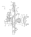
- Suspension subframes 505 and 505 (hereinafter also referred to as “subframes”) formed by casting, for example, aluminum die casting, for supporting the suspension links 542 of the suspension device, below the front side frames 501 and 501. ) are arranged.
- the subframes 505 and 505 may be made of a metal other than aluminum, such as iron. Details of the subframes 505 and 505 will be described later.
- a pair of left and right extension frames 506, 506 formed of a frame member as a load absorbing member extending forward of the vehicle body are connected to the front portions of the sub frames 505, 505.
- a front cross member 561 that extends and connects in the vehicle body width direction is attached to the front ends of the extension frames 506 and 506.
- Sub-crash cans 563 and 563 are connected to the left and right ends of the front cross member 561 via flanges 562 and 562, respectively.
- a lower member 564 is provided in front of the sub-crash cans 563 and 563.
- the lower member 564 is a so-called foot-wiping member that prevents a secondary collision by paying the pedestrian's legs and tilting the pedestrian on the hood when the vehicle collides with the pedestrian.
- a sub cross member 565 that extends in the vehicle width direction and connects the extension frames 506 and 506 is provided at the middle part of the extension frames 506 and 506 in the vehicle longitudinal direction.
- the frame 501 is connected to the lower surface of the front end portion of the 501 by a fastening member (not shown).
- a pair of left and right columnar rear column portions 567 that rises upward while straddling each extension frame 506, 506 from the outside in the vehicle body width direction at a position where the sub cross member 565 is connected in the front-rear direction of each extension frame 506, 506. 567 are provided.
- the upper ends of the rear column portions 567 and 567 are coupled to the lower surfaces of the front side frames 501 and 501 by fastening members (not shown).
- the extension frames 506 and 506 are connected to the front side frames 501 and 501 by the front column portions 566 and 566 and the rear column portions 567 and 567, respectively.
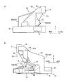
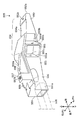
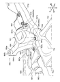
- subframes 505 and 505 will be described in detail with reference to FIGS. 16 to 20, only the subframe 505 on the left side of the vehicle body will be described, but the same applies to the subframe 505 on the right side of the vehicle body.
- the main body portion 550 of the sub-frame 505 is attached to the front portion 551 to which the extension frame 506 is connected, and the rear end portion of the inclined portion 512 of the front side frame 501 while extending in the vehicle body front-rear direction.
- the front portion 551 is disposed on the inner side in the vehicle width direction than the rear portion 552, the front portion 551 and the rear portion 552 are provided offset in the vehicle width direction.
- the intermediate portion 553 connecting the front portion 551 and the rear portion 552 is formed so as to spread from the vehicle body width direction inner side to the vehicle body width direction outer side from the vehicle body front side to the rear side.
- the front end surface of the front portion 551 is provided with a concave connecting portion 551a that opens to the front of the vehicle body.
- the rear end portion of the extension frame 506 is inserted and connected to the connecting portion 551a from the front side of the vehicle body.
- the extension frame 506 and the connecting portion 551a are fastened by fastening members 551b and 551b from the lower surface side of the front portion 551.
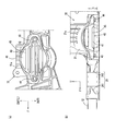
- the rear end portion 552a of the rear portion 552 is provided with a groove portion 552b having a U-shaped cross section in a bottom view that opens rearward and downward in the rear end portion 552a of the rear portion 552.
- the upper surface of the groove 552b is provided with a rear vehicle body attachment portion 552c for fastening the subframe 505 to the rear portion of the inclined portion 512 of the front side frame 501 with a fastening member such as a bolt (see FIG. 18).
- the upper surface portion 554 on the front side of the vehicle body from the groove portion 552b is provided with a thinning portion 554a that is recessed downward in a side view.
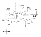
- the intermediate portion 553 is provided with a concave support portion 555 that opens to the outside in the vehicle width direction for supporting the base end portion 543 of the suspension link 542. Details of the support portion 555 of the suspension link 542 will be described later.
- the upper surface portion 554 extends from the rear half portion of the intermediate portion 553 to the rear portion 552 along the lower surface of the inclined portion 512 of the front side frame 501 in the side view. It is inclined to the side.
- an eaves portion 556 as a deformation suppressing portion that spreads outward in the vehicle body width direction is provided in the upper half of the front portion 551 and the intermediate portion 553.
- the eaves portion 556 is formed so as to extend in the vehicle front-rear direction from the front end portion of the front portion 551 to the support portion 555 of the intermediate portion 553.
- the eaves part 556 is inclined upward from the inner side in the vehicle body width direction to the outer side in the vehicle body width direction. This prevents the suspension link 542 and the eaves portion 556 from interfering with each other when the suspension link 542 disposed below the eaves portion 556 swings when the wheels bounce.
- the eaves portion 556 extends from the upper surface to the height of the lower surface of the front portion 511 of the front side frame 501 at a position between the front portion 551 and the intermediate portion 553 in the vehicle longitudinal direction.
- a columnar column portion 557 is provided.
- the column portion 557 is formed in a hollow shape having a columnar space 557a extending from below to above in the inside thereof.
- a second vehicle body attachment portion 557b for attaching the sub frame 505 to the lower surface of the front portion 511 of the front side frame 501 with a fastening member such as a bolt is provided on the upper surface of the column portion 557.
- the second vehicle body attachment portion 557b is rigidly coupled without using a damping element such as a rubber bush. Thereby, the rigidity between the column part 557 which comprises the 2nd intermediate vehicle body attaching part 557b, and the front side frame 501 is improved. Note that the space 557a in the column portion 557 is provided as an insertion portion into which a tool for inserting the sub frame 505 to the front side frame 501 is inserted.
- a rib portion 558 extending from the rear end of the second vehicle body attachment portion 557 b to the rear portion of the eave portion 556 is provided on the upper surface of the eave portion 556.
- the rib portion 558 is formed to be inclined downward toward the rear of the vehicle body along the lower surface of the inclined portion 512 of the front side frame 501 in a side view of the vehicle body.
- An upper surface 558 a of the rib portion 558 is formed continuously from the intermediate portion 553 to the upper surface portion 554 of the rear portion 552.
- the second vehicle body attachment portion 557b and the rear vehicle body attachment portion 552c are formed to be continuous by the rib portion 558 and the upper surface portion 554.
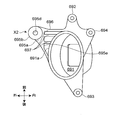
- a mount receiving portion 559 as a mount support portion for supporting an engine mount (not shown) for mounting the engine 502 is provided on the rear side of the connecting portion 551 a of the front portion 551. Is provided.
- the mount receiving portion 559 has a cylindrical portion 559a whose upper side is inclined to the inner side of the vehicle body from the lower side, and a bottom portion 559b that covers the lower end portion of the cylindrical portion 559a.
- the mount receiving portion 559 is formed so that its upper side bulges inward in the vehicle body width direction (engine room side) and its lower side bulges below the eaves portion 556 outside in the vehicle width direction.
- a drain hole 559c is provided on the inner side in the vehicle width direction of the bottom portion 559b.
- Mounting holes 559d to 559d are provided outside the mount receiving portion 559, and a rubber bush cover 521 (see FIG. 15) of the engine mount is fixed by a fastening member such as a bolt.
- the lower arms 541 and 542 of the suspension device of this embodiment are formed by two lower arms 541 and 542.
- the lower arm 541 on the front side of the vehicle body is constituted by a lateral link extending in the vehicle body width direction, and the end portion on the inner side in the vehicle width direction of the lateral lower arm 541 is the rear of the extension frame 506. It is swingably supported by a bracket (not shown) attached to the rear side of the side column portion 567.
- the lower arm 542 on the rear side of the vehicle body is formed of a compression link, and the compression lower arm 542 moves forward from the support portion 555 of the subframe 505 toward the outside in the vehicle width direction. It is provided so that it may extend.
- the end portion of the compression lower arm 542 on the inner side in the vehicle width direction is supported by the support portion 555 through a bush so as to be swingable.
- the “suspension link” in the claims corresponds to a “compression lower arm”.
- the ends of the lower arms 541 and 542 on the outer side in the vehicle width direction are coupled to a knuckle 571 schematically shown so as to be rotatable around an axis extending in the vertical direction.
- the knuckle 571 supports the front wheel 572 rotatably via a hub (not shown).
- the support portion 555 is provided with both wall portions 555a and 555b in the longitudinal direction of the vehicle body that form a recess. Both wall portions 555a and 555b are provided with insertion holes 555c and 555d for inserting pins that support the bushing 544 that is press-fitted into the base end portion 543 of the compression lower arm 542, respectively.
- the intermediate portion 553 includes a thinning portion 553a that opens in the vehicle width direction inside the support portion 555 in front of the vehicle body, and a removal portion that opens outward in the vehicle width direction in the vehicle rear direction of the support portion 555.
- a meat portion 553b is formed.
- These thinning portions 553a and 553b also function as insertion portions for inserting a tool when attaching the compression lower arm 542 to the subframe 505.
- the compression lower arm 542 swings with the line segment connecting the insertion holes 555c and 555d as the rotation axis a.
- the rotation axis a is provided such that the front side of the vehicle body is inclined inward in the vehicle body width direction in plan view.
- a line segment b connecting the rear vehicle body attachment portion 552c and the second vehicle body attachment portion 557b extends in the vehicle body front-rear direction.
- the line segment b and the rotation axis a have a relationship that intersects in plan view.
- the front side frames 501 and 501 and the extension frames 506 and 506 start to deform after the front crashes of the main crash cans 516 and 516 and the sub crash cans 563 and 563 at the time of a frontal collision of the vehicle. Since 501 and 501 and the extension frames 506 and 506 cooperate to deform and absorb the impact, the load input at the time of the front collision can be absorbed by two paths and transmitted to the vehicle body.
- subframes 505 and 505 are connected to the rear ends of the extension frames 506 and 506.
- the sub frames 505 and 505 are two vehicle body mounting portions 552c, 552c, 557b, and 557b, front portions 511 and 511 of the front side frames 501 and 501, and rear portions of the inclined portions 512 and 512 of the front side frames 501 and 501, respectively. It is concluded to. Thereby, since the support rigidity of the sub-frames 505 and 505 is enhanced, the shock absorbing function of the extension frames 506 and 506 can be promoted.
- the rotation axis a of the compression lower arm 542 and a line segment b connecting the rear vehicle body attachment portion 552c and the second vehicle body attachment portion 557b intersect with each other in a plan view.
- the behavior change of the vehicle is achieved by providing the support portion 555 of the compression lower arm 542 in a portion where the mounting rigidity is increased by providing the rear vehicle body mounting portion 552c and the second vehicle body mounting portion 557b in the subframe 505.
- the vehicle body can efficiently receive the input from the compression lower arm 542.
- an increase in weight and an increase in structure due to increasing the rigidity of the subframe 505 itself can be avoided.
- sub-frames 505 and 505 are provided with power train mount receiving portions 559 and 559, they have a function of supporting the power train mount.
- the subframes 505 and 505 have the three functions of the suspension link support function, the powertrain mount support function, and the function of promoting shock absorption during the front collision.
- the subframe 505 combines the functions of the left and right sides and the tower, the number of parts and the number of assembly steps can be reduced. it can.
- subframes 505 and 505 are divided into left and right parts, as compared with the case where the pair of right and left side parts are connected via the front side part as in the subframe described in Patent Document 1 described above. Thus, an increase in weight can be suppressed.
- the load absorption of the extension frames 506 and 506 is promoted by the subframes 505 and 505, and the engine 502 is supported by the subframes 505 and 505 in addition to reliably absorbing the front impact load. It can be effectively suppressed.
- the column portion 557 constituting the second vehicle body attachment portion 557b is integrally provided on the upper surface of the mount receiving portion 559. That is, the sub frame 505 is fixed to the front side frame 501 at the mount receiving portion 559. Therefore, also in the second embodiment, vibrations of the power trains 502 and 503 that cannot be absorbed by the PT mount (not shown) are directly transmitted from the mount receiving portion 559 to the front side frame 501. Therefore, the vibration transmission path from the mount receiving portion 559 to the front side frame 501 can exhibit vibration characteristics close to a rigid body as a whole, and thus the PT mount exhibits a desired damping performance, so that the power train 502, The vibration of 503 can be effectively reduced.
- the front vehicle body structure 601 provided with the subframe structure 700 of the present embodiment will be described with reference to FIGS.
- the front body structure 601 is arranged along a front surface of a pair of left and right front side frames 620 and 620 extending in the longitudinal direction of the vehicle body and a dash panel (not shown).
- a dash cross 630 that connects the side frames 620 and 620 and a subframe structure 700 that is disposed below the front side frames 620 and 620 are provided.
- the vehicle drive system is the front engine rear drive (FR).
- FR front engine rear drive
- a power train 640 including a vertically installed engine 641 and a transmission 642 connected to the rear portion is disposed (see FIG. 23).
- Each of the front side frames 620 and 620 has a front straight portion 621 and 621 extending substantially horizontally from the dash cross 630 toward the front, and an inclination extending obliquely downward from the rear end portion of the front straight portions 621 and 621 toward the rear of the vehicle body.
- Parts 622, 622, and rear straight parts 623, 623 extending substantially horizontally rearward from the lower ends of the inclined parts 622, 622.
- the front straight portions 621 and 621 of the front side frames 620 and 620 respectively have inner panels 624 and 624 located on the inner side in the vehicle body width direction and outer panels 625 and 625 located on the outer side in the vehicle body width direction. It is configured to be joined in the direction.
- the inner panels 624 and 624 have a cross-sectional hat shape opened to the outer side in the vehicle body width direction
- the outer panels 625 and 625 have a cross-sectional hat shape opened to the inner side in the vehicle body width direction and extend in the longitudinal direction of the vehicle body.
- the outer panels 625 and 625 and the inner panels 624 and 624 are joined to each other between their upper edges and between their lower edges. Accordingly, the front straight portions 621 and 621 form a closed cross section that is continuous in the longitudinal direction of the vehicle body by the frame itself.
- the inclined portions 622 and 622 of the front side frames 620 and 620 have a cross-sectional hat shape opened to the upper side.
- the inclined portions 622 and 622 are arranged so that the rear side of the vehicle body is lowered along the shape of the dash panel (not shown), and the upper edges of the inclined portions 622 and 622 are joined to the dash panel.
- a closed cross section that is continuous in the longitudinal direction of the vehicle body is formed between the inclined portions 622 and 622 and the dash panel.
- the rear straight portions 623 and 623 of the front side frames 620 and 620 are connected to the front end portion of a floor frame (not shown) extending in the longitudinal direction of the vehicle body at the rear end portion.
- a floor panel (not shown) is joined to the rear straight portions 623 and 623 and the floor frame, and the front edge of the floor panel is connected to the dash panel.
- the rear straight portions 623 and 623 and the floor frame have a cross-sectional hat shape opened to the upper side, and a closed cross section that is continuous in the longitudinal direction of the vehicle body is formed between the rear straight portions 623 and 623 and the floor frame.
- Main crush cans 653 and 653 made of a cylindrical body or the like that absorbs an impact load from the front of the vehicle body are connected to the front ends of the front side frames 620 and 620 via set plates 651 and 651 and mounting plates 652 and 652, respectively.
- a bumper reinforcement 654 extending in the vehicle width direction is attached to the front end surfaces of the pair of left and right main crash cans 653 and 653.
- the subframe structure 700 is disposed below the front side frame 620 and supports a pair of left and right subframes 710 and 710 that support lower arms 660 and 660 as suspension links for front wheels, and front ends of the subframes 710 and 710. And a pair of left and right extension frames 730, 730 extending forward of the vehicle body, and first to third cross members 740, 750, 760 connecting the left and right frames 710, 710, 730, 730.
- the sub-crash cans 655 and 655 extend forward from the front ends of the extension frames 730 and 730, respectively.
- a sub-bumper reinforcement 658 extending in the vehicle body width direction is provided in front of the sub-crash cans 655 and 655.
- the left and right sub-crash cans 655 and 655 are connected to each other via a sub-bumper reinforcement 658.
- the lower arms 660 supported by the subframes 710 and 710 extend substantially horizontally from the front arm portion 661 extending substantially parallel to the vehicle body width direction and from the middle portion of the front arm portion 661 to the vehicle body width direction inward and rearward.
- the lower arm 660 is formed in a substantially L shape in plan view as a whole.
- a front connection portion 661a that is connected to a relatively front portion of the subframe 710 and a rear connection portion 662a that is connected to a relatively rear portion of the subframe 710 are formed. Yes.
- the front connection portion 661a is provided at the inner end in the vehicle width direction of the front arm portion 661, and the rear connection portion 662a is provided at the rear end portion of the rear arm portion 662.
- the front side connecting portion 661a of the front arm portion 661 is swingable about an axis extending in the longitudinal direction of the vehicle body by a front side bracket 663 attached across the front end portion of the subframe 710 and the rear end portion of the extension frame 730. It is supported.
- the rear connecting portion 662a of the rear arm portion 662 is supported by a rear bracket 664 attached to the subframe 710 so as to be swingable around an axis extending in the vehicle longitudinal direction.
- the subframe 710 has a main body 711 that supports the lower arm 660.
- the rear end of the extension frame 730 is connected to the front end 712 of the main body 711 of the subframe 710.
- the rear end 713 of the main body 711 is fixed to the front side frame 20 via a rear vehicle body attachment portion X3 described later.
- the main body portion 711 of the subframe 710 is a long portion disposed so as to extend in the longitudinal direction of the vehicle body.
- the main body 711 includes an upper member 714 having a U-shaped cross section that opens downward, and a lower member 715 having a U-shaped cross section that opens upward.
- the lower edge portion of the upper member 714 and the upper edge portion of the lower member 715 are joined to each other by welding, for example.
- the main body 711 forms a closed cross section that is continuous in the longitudinal direction of the vehicle body between the upper member 714 and the lower member 715.
- the upper member 714 includes an upper surface portion 714a, an outer surface portion 714b and an inner surface portion 714c in the vehicle body width direction
- the lower member 715 includes a lower surface portion 715a, an outer surface portion 715b and an inner surface portion in the vehicle body width direction. 715c.
- the outer surface portions 714b and 715b of the upper member 714 and the lower member 715 and the inner surface portions 714c and 715c are joined to form a closed cross section that is continuous in the longitudinal direction of the vehicle body (see FIG. 25 (d)).
- the upper member 714 and the lower member 715 form an opening 716 (see FIG. 25A) at the front end 712 of the main body 711 of the subframe 710.
- the extension frame 730 includes an upper member 731 having an upper U-shape having a U-shaped cross section that opens downward, like the main body 711 of the subframe 710, With the lower member 732 having a U-shaped cross section that is open to the bottom, a closed cross section that is continuous in the longitudinal direction of the vehicle body is formed by the frame itself.
- the upper member 731 includes an upper surface portion 731a, an outer surface portion 731b and an inner side surface portion 731c in the vehicle width direction
- the lower member 732 includes a lower surface portion 732a, an outer surface portion 732b and an inner surface portion in the vehicle width direction. 732c.
- the outer surface portions 731b and 732b of the upper member 731 and the lower member 732, and the inner surface portions 731c and 732c are joined to form a closed cross section that is continuous in the longitudinal direction of the vehicle body (see FIG. 25C).
- the rear end portion 733 of the extension frame 730 is formed so that the outer diameter is smaller than the portion on the front side of the rear end portion 733.
- both the frames 710 and 730 are connected to each other.
- both the frames 710 and 730 are joined by welding or the like, for example.
- the extension frame 730 and the sub frame 710 are integrally connected in the longitudinal direction of the vehicle body (see FIG. 25A).
- the extension frame 730 is set to have lower rigidity with respect to the input load in the vehicle longitudinal direction than the sub frame 710.
- the front extension frame 730 can have a load absorbing function
- the rear sub frame 710 can have a function as a load receiving portion.
- first to third cross members 740, 750, 760 provided between the left and right subframes 710, 710 and the extension frames 730, 730 of the subframe structure 700 will be described with reference to FIG.
- a frame-shaped first cross that extends substantially linearly so that the front end portions 734, 734 of the pair of left and right extension frames 730, 730 bridge the front end portions 734, 734 of the extension frames 730, 730 in the vehicle body width direction.
- a member 740 is attached.
- the connecting portion 680 between the right subframe 710 and the extension frame 730 and the connecting portion 680 between the left subframe 710 and the extension frame 730 are connected to each other via the second cross member 750.
- the second cross member 750 includes a front side portion 751 extending between the left and right extension frames 730 and 730 in the vehicle body width direction, and a left and right side portion 752 extending from the left and right ends of the front side portion 751 to the vehicle body rear side. 752 and a reinforcing frame 753 disposed between the left and right side portions 752 and 752.
- the reinforcing frame 753 extends in the vehicle body width direction between the rear end portions of the left and right side portions 752 and 752 in the vehicle body width direction, and extends between the horizontal frame portion 754 and the front side portion 751 in the vehicle body front-rear direction.
- a vertical frame portion 755 connected to each other.
- the front side portion 751 has a U-shaped front side portion upper member 756 that extends in the vehicle body width direction and is opened downward, and an open surface of the front side portion upper member 756. And a plate-like lower member 759 for closing the door.
- the lower member 759 has a width wider than the front side upper member 756 in the longitudinal direction of the vehicle body, and is disposed so as to protrude rearward from the front side upper member 756. Further, the lower member 759 is disposed in the vehicle body front-rear direction region straddling the extension frame 730 and the subframe 710.
- the front side upper member 756 has an upper surface portion 756a, a front surface portion 756b, and a rear surface portion 756c.
- the front side upper member 756 is disposed on the upper surface 759 a of the lower member 759, and the front surface portion 756 b is disposed along the front end 759 b of the lower member 759.
- the lower end portions of the front surface portion 756b and the rear surface portion 756c are joined to the upper surface of the lower member 759, whereby a closed cross section that is continuous in the vehicle body width direction is formed between the front side upper member 756 and the lower member 759. ing.
- the upper surface portion 756a of the front side upper member 756 is joined to the upper surface portions 731a and 731a of the extension frames 730 and 730 at both edges 756d and 756d in the vehicle body width direction. .
- both end portions 759c and 759c of the lower member 759 in the vehicle width direction are provided on the lower surface portions 732a and 732a of the extension frames 730 and 730 and the sub frames 710 and 710, respectively.
- the main body portions 711 and 711 are joined to the lower surface portions 715a and 715a.
- the left and right side portions 752 and 752 are composed of left and right side upper members 757 and 757 that are integrally connected to the aforementioned front side upper member 756 and the aforementioned lower member 759. Yes.
- the left and right side upper members 757 are arranged so as to extend in the longitudinal direction of the vehicle body, and are connected to the front side upper member 756 at the front end thereof.
- the front side upper member 756 and the left and right side upper members 757 and 757 are formed in a U shape that opens to the rear side of the vehicle body in plan view (see FIG. 23).
- the inner edge 757b is arranged lower than the outer edge 757a in the vehicle body width direction.
- the left and right side upper members 757 have slope portions 757c that gradually decrease from the outer edge portion 757a toward the inner edge portion 757b.
- the inner edge portions 757b and 757b of the left and right side upper members 757 and 757 are joined to the upper surface 759a of the lower member 759, and the outer edge portions 757a and 757a are the upper surface portions 714a and 714a of the main body portions 711 and 711 of the subframes 710 and 710, respectively. It is joined to.
- the left and right side upper members 757 and 757, the lower member 759, and the inner side surface portions 714c and 715c of the main body portions 711 and 711 of the sub frames 710 and 710 form a closed cross section that is continuous in the vehicle body front-rear direction. Yes.
- the left and right side portions 752 and 752 of the second cross member 750 have a width that is gradually enlarged toward the front side of the vehicle body in a plan view.
- Reinforcing portions 751A and 751A having arcuate contours are formed at the corner portions between the front side portion 751 and the left and right side portions 752 and 752, respectively.
- the second cross member 750 includes the horizontal frame portion 754 that connects the rear end portions of the left and right side portions 752 and 752 of the second cross member 750, and the intermediate portion and the front side portion 751 of the horizontal frame portion 754.
- a reinforcing frame 753 having a substantially T-shape is provided by a vertical frame portion 755 that connects the intermediate portion.
- the horizontal frame portion 754 is formed in a U-shaped cross section that extends in the vehicle body width direction and is opened downward.
- the vertical frame portion 755 is formed in a U-shaped cross section that extends in the longitudinal direction of the vehicle body and is opened downward.
- the horizontal frame portion 754 has an upper surface portion 754a, a front surface portion 754b in front of the vehicle body, and a rear surface portion 754c at the rear of the vehicle body, and the rear surface portion 754c is disposed along the rear end portion 759d of the lower member 759. .
- the front surface portion 754 b and the rear surface portion 754 c of the horizontal frame portion 754 are joined to the upper surface of the lower member 759.
- a closed cross section that is continuous in the vehicle body width direction is formed between the horizontal frame portion 754 and the lower member 759.
- both side portions 754d and 754e of the horizontal frame portion 754 are joined to slope portions 757c and 757c of the left and right side portions 752 and 752, respectively (see FIGS. 23 and 24).
- the vertical frame portion 755 has an upper surface portion 755a and both side surface portions 755b and 755b in the vehicle body width direction, and the lower end portions of the both side surface portions 755b and 755b are joined to the lower member 759.
- a closed cross section that is continuous in the longitudinal direction of the vehicle body is formed between the vertical frame portion 755 and the lower member 759.
- the front end portion 755c of the vertical frame portion 755 is joined to the rear surface portion 756c of the front side portion 751.
- the outer edge portions 756d, 756d of the front side upper member 756 of the second cross member 750 and the outer edge portions 757a, 757a of the left and right side upper members 757, 757 are the rear end portions 733 of the extension frames 730, 730. , 733 and the upper surface portions 714a and 714a of the front end portions 712 and 712 in the sub-frames 710 and 710, respectively.
- Both end portions 759c and 759c of the lower member 759 are joined to the lower surface portions 732a and 732a of the rear end portions 733 and 733 in the extension frames 730 and 730 and the lower surface portions 715a and 715a of the front end portions 712 and 712 in the sub frames 710 and 710, respectively. ing.
- the second cross member 750 extends over the connection portion 680 between the extension frame 730 and the sub frame 710 and is joined so as to be gripped from the inner side in the vehicle body width direction.
- the folding of the connecting portion 680 between the vertical direction and the vehicle body width direction is suppressed.
- the lower arm 660 of the suspension device is attached to the front bracket on the outer surface 732b, 731b, 714b, 715b side of the rear end portion 733 of the extension frame 730 and the front end portion 714d of the subframe 710 in the vehicle width direction. 663 is supported.
- the front bracket 663 has a rear end portion 733 of the extension frame 730 and a front end portion 714d of the subframe 710 on the outer side surfaces 732b, 731b, 714b, 715b side in the vehicle body width direction.
- the lower surface portions 715a and 732a are joined to both the frames 710 and 730 so as to be continuous (W).
- connection portion 680 between the extension frame 730 and the sub frame 710 is reinforced by the left and right side portions 752 of the second cross member 750 on the inner side in the vehicle body width direction, and is reinforced by the front bracket 663 on the outer side in the vehicle body width direction.
- the front bracket 663 is used on the outer side in the vehicle body width direction to reinforce the connection portions 680 of both frames 710 and 730 without adding parts.
- the outer end of the second cross member 750 in the vehicle width direction is joined across the extension frame 730 and the subframe 710. That is, the joint region Z of the second cross member 750 with respect to the extension frame 730 and the subframe 710 includes an extension frame side joint region 681 joined to the extension frame 730 and a subframe side joint region 682 joined to the subframe 710. have.
- the extension frame side joining area 681 is set to be shorter than the subframe side joining area 682 as the dimension of the joining area Z in the longitudinal direction of the vehicle body.
- extension frame side joining region 681 By preventing the extension frame side joining region 681 from being formed longer than necessary, it is possible to prevent the second cross member 750 from inhibiting the deformation of the extension frame 730 when an impact load is input from the front of the vehicle body. Has been. Therefore, the shock absorbing function of the extension frame 730 can be satisfactorily exhibited.
- the subframe-side joining region 682 is formed to be relatively long, the strength and rigidity of the subframe 710 with respect to the load in the longitudinal direction of the vehicle body are improved. Therefore, when an impact load is input from the front of the vehicle body, the subframes 710 and 710 can exhibit a function as a load receiving portion, and thus the extension frames 730 and 730 can perform an impact absorbing function satisfactorily. It is possible.
- a third cross member 760 that connects the rear end portions 713, 713 to each other in the vehicle body width direction is connected to the rear end portions 713, 713 of the subframes 710, 710.
- the third cross member 760 is a plate member extending in the vehicle body width direction, and is fixed to the rear end portions 713 and 713 of the subframes 710 and 710 from below by a plurality of bolts 761.
- the above-described subframe structure 700 has front vehicle body attachment portions X1, X1 and intermediate vehicle body attachment portions X2, as attachment portions to the front side frames 620, 620, respectively.
- X2 and the rear vehicle body attachment portions X3 and X3 are provided at three locations, each of which will be described below.
- the front vehicle body attachment portion X1 is configured by a connection member 671 provided at the front end portion 734 of the extension frame 730.
- the connection member 671 has a lower portion 672 connected to the extension frame 730, and is formed in a tower shape extending upward from the connection location.
- connection member 671 is formed in a hollow box shape, and the upper surface portion 673 of the outer portion in the vehicle body width direction is a fastening member 675 with respect to the lower surface 625a of the outer panel 625 of the front side frame 620 via the mount bush 674. Is attached by.
- a sub-crash can 655 is connected to the vertical wall-shaped front surface 676 of the connection member 671 via a mounting plate 657.
- the intermediate vehicle body mounting portion X2 includes a power train mount bracket (hereinafter also simply referred to as “mount bracket”) 690 for housing a power train mount (not shown) for elastically supporting the power train 604.
- mount bracket for housing a power train mount (not shown) for elastically supporting the power train 604.
- the “mount support part” in FIG. Details of the mount bracket 690 will be described later.
- the rear vehicle body attachment portion X3 is provided on the side of the rear end portion 713 of the main body portion 711 of the suspension subframe 710, as shown in FIGS.
- the rear vehicle body attachment portion X3 includes an upper plate member 721 disposed on the upper side and a lower plate member 722 disposed on the lower side.
- the upper plate member 721 and the lower plate member 722 are respectively provided on side edge portions 721a and 722a extending in parallel with the outer side surfaces 714b and 715b of the suspension subframe 710 in the vehicle body width direction, and on the rear side of the vehicle body.
- Front edge portions 721b, 722b extending in a direction inclined outward in the vehicle body width direction, and rear edge portions 721c, 722c connecting the side edge portions 721a, 722a and the rear edge portions of the front edge portions 721b, 722b, As a whole, it is formed in a substantially triangular shape in plan view.
- the upper plate member 721 and the lower plate member 722 are coupled to each other by welding flange portions (not shown) provided on the respective rear edge portions 721c and 722c.
- the side edge portion 721a of the upper plate member 721 is joined to the upper surface 714a of the rear portion of the body portion 711 of the suspension subframe 710, for example, by welding, and the side edge portion 722a of the lower plate member 722 is joined to the body portion of the suspension subframe 710. 711 is joined to the rear lower surface 715a.
- the rear vehicle body attachment portion X3 is joined to the main body portion 711 of the suspension subframe 710.
- the suspension subframe 710 is fastened to the front side frame 620 at a position spaced apart from the body portion 711 of the suspension subframe 710 to the outside in the vehicle width direction on the upper plate member 721 and the lower plate member 722 of the rear vehicle body attachment portion X3.
- Bolt insertion holes 721e and 722e are provided.
- a sleeve member 724 (see FIG. 1) fixed to the front side frame 620 by a bolt 725 is interposed.
- the sleeve member 724 is connected to the main body 711 via the upper plate member 721 and the lower plate member 722.
- a bracket 626 for fixing the rear vehicle body attachment portion X3 is joined to the rear end portion of the inclined portion 622 of the front side frame 620 from below.
- a weld nut (not shown) into which the bolt 725 is screwed is joined to the upper surface of the bracket 626.
- mount bracket 690 will be described in detail with reference to FIGS.
- the mount bracket 690 is integrally formed by casting such as aluminum die casting.
- the material of the mounting bracket 690 is not limited to aluminum.
- the mount bracket 690 is provided with a hollow housing portion 691 having a housing space opened downward.
- the accommodating portion 691 is formed in a cylindrical shape, for example.
- the accommodation portion 691 accommodates a mount support structure (not shown) connected to a power train side bracket provided on the power train 604 side.
- a mount support structure since it is the same as that of 1st Embodiment, description is abbreviate
- Each mounting bracket 690 is provided with a plurality of fastening portions 692, 693, and 694 for fastening to the subframe structure 700.
- the plurality of fastening portions 692, 693, and 694 include a front side fastening portion 692 provided at the front edge portion of the mount bracket 690, a rear side fastening portion 693 provided at the rear edge portion of the mount bracket 690, and the vehicle body longitudinal direction. It is comprised by the intermediate
- These fastening portions 692, 693, and 694 are composed of a plurality of flange portions 692a, 693a, and 694a extending outward from the lower end portion of the outer peripheral portion 691a of the housing portion 691 in the mount bracket 690.
- These flange portions 692a, 693a, and 694a are provided with bolt insertion holes (not shown).
- the bolts 692c, 693c, and 694c inserted into the bolt insertion holes provide the subframe 710 and the second cross member 750 with each other. It is concluded.
- the sub frame 710 is provided with bolt fastening holes 711a and 711b for attaching the mount bracket 690 at positions corresponding to the bolt insertion holes of the front fastening portion 692 and the rear fastening portion 693 of the mount bracket 690. (See FIG. 24).
- the front fastening portion 692 is fixed to the subframe 710 at a position close to the front bracket 663 of the front lower arm 661 of the suspension device, and the rear fastening portion 693 is a rear bracket of the rear lower arm 662 of the suspension device. It is fixed to the subframe 710 at a position close to 664. As a result, the vibration due to the swing of the suspension device can be received by the portion of the subframe 710 where the mount bracket 690 is fastened and having high rigidity.
- Bolt fastening holes 752a for attaching the mount bracket 690 are provided in the left and right side portions 752 of the second cross member 750 at positions corresponding to the bolt insertion holes 694b of the intermediate fastening portion 694 (see FIG. 24). .
- the intermediate fastening portion 694 is fixed to the rear end portions 752b of the left and right side portions 752 of the second cross member 750 at substantially the same position as the horizontal frame portion 754 of the reinforcing frame 753 in the longitudinal direction of the vehicle body.
- the fastening portion of the mount bracket 690 will be described with the intermediate fastening portion 694 as an example with reference to FIG.
- the intermediate fastening portion 694 is fastened to the rear end portion 752b of the left and right side portions 752 of the second cross member 750 as described above.
- the left and right side portion upper members 757 have a substantially L-shaped cross section that opens outward and downward in the vehicle body width direction when viewed from the vehicle longitudinal direction.
- Bolt insertion holes 757 e for fastening the mount bracket 690 are provided on the upper surface 757 d of the left and right side upper members 757.
- the lower member 759 is provided with a bolt insertion hole 759e at a position corresponding to the bolt insertion hole 757e of the left and right side upper member 757, and the lower surface 759f of the lower member 759 corresponding to the bolt insertion hole 759e of the lower member 759 is A weld nut 759g is joined.
- a sleeve member 759 h is disposed between the left and right side upper members 757 and the lower member 759.
- the bolt 694c has a bolt insertion hole 694b from above the intermediate fastening portion 694, a bolt insertion hole 757e of the left and right side upper member 757, a sleeve member 759h, and a bolt insertion hole 759e of the lower member 759.
- the second cross member 750 is fastened and fixed to the upper surface 757d of the rear end portion 752b of the left and right side portions 752 by being penetrated and screwed into the weld nut 759g.
- the mount bracket 690 is fastened to the upper surface 714 a of the subframe 710 by bolts 692 c and 693 c, a sleeve member, and a weld nut. As a result, the mount bracket 690 is fastened to the sub-frame 710.
- the mount bracket 690 is provided as the intermediate mounting portion X2 so as to extend upward from the above-described housing portion 691, a base portion 695a disposed in the vehicle width direction outer side of the housing portion 691, and the base portion 695a. 691 and a columnar portion 695b disposed diagonally upward in the vehicle body width direction.
- the intermediate vehicle body attachment portion X2 is connected to the housing portion 691 via a connection surface portion 696 extending from the upper wall surface portion 691b of the housing portion 691 to the outside in the vehicle body width direction.
- a vehicle body width direction outer side end portion 696a of the connection surface portion 696 constitutes an upper surface portion of the base portion 695a, and is connected to an intermediate portion in the height direction of the columnar portion 695b.
- An inner end 696b in the vehicle width direction of the connection surface portion 696 is continuous with the upper wall surface portion 691b of the housing portion 691.
- the columnar portion 695b is connected to the outer end of the base portion 695a in the vehicle width direction at the lower end thereof.
- the columnar portion 695b is formed with a bolt insertion hole 695d that vertically penetrates the columnar portion 695b.
- a bolt insertion hole 625b is provided in the lower surface portion 625a of the outer panel 625 at the rear portion of the front linear portion 621 of the front side frame 620, and corresponds to the bolt insertion hole 625b on the upper surface of the lower surface portion 625a of the outer panel 625.
- a weld nut 625c is joined to the position.
- Bolts 695c inserted into the bolt insertion holes 695d of the columnar portion 695b and the bolt insertion holes 625b of the outer panel 625 from below are screwed into the weld nuts 625c, so that the lower surface of the front side frame 620 is intermediate the mount bracket 690.
- the vehicle body attachment portion X2 is rigidly coupled without using a damping element such as a rubber bush. Thereby, the rigidity between the intermediate vehicle body attachment portion X2 and the front side frame 620 is enhanced.
- the intermediate vehicle body attachment portion X2 is provided at a position overlapping the lower arm 660 in plan view, but the lower arm 660 has a hole at a position corresponding to the intermediate vehicle body attachment portion X2.
- a portion 660a is provided (see FIG. 28).
- the accommodating portion 691 of the mount bracket 690 is arranged such that the axis of the outer peripheral portion 691a is inclined inward in the vehicle body width direction toward the upper side. That is, the outer peripheral portion 691a is provided so as to be inclined so that the inner edge portion 691c in the vehicle body width direction is positioned lower than the outer edge portion 691d when viewed from the vehicle longitudinal direction.
- each rib 697 is formed of a plate-like portion disposed along a plane perpendicular to the longitudinal direction of the vehicle body (see FIG. 28).
- the rib 697 includes the side surface portion 695e of the base portion 695a in the vehicle width direction and the lower surface 696c of the connection surface portion 696 so as to connect the base portion 695a constituting the intermediate vehicle body attachment portion X2 and the housing portion 691. And the outer peripheral portion 691a of the accommodating portion 691 are connected. Thereby, the rigidity between the intermediate vehicle body attachment portion X2 and the accommodating portion 691 is enhanced.
- the rib 697 is provided so as to extend in the vertical direction along the side surface portion 695e of the base portion 695a in the vehicle body width direction and the outer peripheral portion 691a of the housing portion 691.
- the lower edge portion of 697 is formed to extend obliquely upward from the outer peripheral portion 691a of the housing portion 891 toward the side surface portion 695e of the base portion 695a in the vehicle width direction.
- the distance in the vehicle width direction between the outer end portion 691a of the housing portion 691 in the vehicle width direction and the center line L2 of the bolt 695c is the dimension in the vehicle width direction of the front side frame 620.
- the suspension subframe 710 is formed so as to be smaller than the vehicle body width direction dimension and the diameter of the accommodating portion 691.
- the intermediate vehicle body attachment portion X2 is disposed in the vicinity of the housing portion 691 in the vehicle body width direction.
- a straight line L1 extending along the outer edge portion 691d and the center line L2 of the bolt 695c of the intermediate vehicle body attachment portion X2 are horizontal from the lower surface 715a of the subframe 710 when viewed from the vehicle longitudinal direction. It is preferable to be arranged so as to intersect at a point P located on the straight line L3 extending in the direction or above the straight line L3. Thereby, compared to the case where the straight line L1 and the center line L2 intersect at a point below the lower surface 715a of the subframe 710, the housing portion 691 and the vehicle body attachment portion X2 are connected in the vehicle width direction. Can be arranged closer to each other.
- the intermediate vehicle body attachment portion X2 is disposed close to the housing portion 691 in the vehicle body width direction.
- the side surface portion 695e inside the base portion 695a in the vehicle body width direction of the intermediate vehicle body attachment portion X2 is adjacent to the outer peripheral portion 691a of the housing portion 691 in the vehicle body width direction.
- the housing portion 691 is effectively reinforced by the intermediate vehicle body attachment portion X2 disposed adjacent to the housing portion 691 and the ribs 697.
- the main body 711 of the sub-frame 710 is fixed to the front side frame 620 via the mount bracket 690. Therefore, the vibration of the power train 604 that cannot be absorbed by the mount is transmitted from the mount bracket 690 to the vehicle body without passing through the main body 711.
- the vibration transmission path from the housing portion 691 to the vehicle body attachment portion X2 adjacent thereto is formed to be extremely short, and the rigidity is enhanced by the ribs 697. Therefore, the vibration transmission path from the housing portion 691 of the mount bracket 690 to the vehicle body attachment portion X2 can exhibit vibration characteristics close to a rigid body as a whole. As a result, the vibration of the power train 604 can be effectively reduced because the mount exhibits desired damping characteristics.
- the intermediate vehicle body attachment portion X2 and the intermediate fastening portion 694 described above are disposed across the subframe 710 in the vehicle body width direction. Since the intermediate vehicle body attachment portion X2 and the intermediate fastening portion 694 are provided with a large offset amount in the vehicle body width direction, deformation of the mount bracket 690 in the vehicle body width direction can be suppressed.
- the mount bracket 690 is fixed not only to the subframe 710 but also to the second cross member 150, the mount bracket 690 can be supported in a wide region in the vehicle body width direction. Thereby, when the sub-frame 710 and the mount bracket 690 are separate bodies, the displacement that causes the mount bracket 690 to fall inward in the vehicle body width direction is suppressed.
- the present invention is not limited to the configuration of the above-described embodiment, and can be formed in various embodiments.
- the PT frame mounting function of the subframe and the shock absorbing function at the time of impact load input from the front of the vehicle body are enhanced, Since vibration can be reduced more effectively, it may be suitably used in the field of manufacturing the vehicle body of a vehicle.
Landscapes
- Engineering & Computer Science (AREA)
- Mechanical Engineering (AREA)
- Chemical & Material Sciences (AREA)
- Combustion & Propulsion (AREA)
- Transportation (AREA)
- Architecture (AREA)
- Structural Engineering (AREA)
- Body Structure For Vehicles (AREA)
Abstract
サブフレーム構造は、車両の車体構造体(620)に対して下方に配設されるサブフレーム(710)と、該サブフレーム(710)から前方に延びて車体前方からの衝撃荷重を吸収するエクステンションフレーム(730)とを備え、前記サブフレーム(710)は、車体前後方向に延びる本体部(711)と、マウントを介してパワートレイン(604)を支持するマウント支持部(690)とを有し、前記本体部(711)は、前記マウント支持部(690)を介して前記車体構造体(620)に固定されている。
Description
本発明はサブフレーム構造に関し、自動車等の車両の車体構造の技術分野に属する。
一般に車体前部構造としては、車両の前後方向に延びて車体前部を支える左右一対のフロントサイドフレームが設けられ、該フロントサイドフレームの下方に、パワートレインを支持するためのサブフレームが配設されたものが知られている。
特許文献1に開示された車体前部構造は、フロントサイドフレームの下方に配置される左右辺部、および該左右辺部の前端を車幅方向に連結する前辺部を有して、平面視で後方に開放してU字状に形成されたサブフレームと、前述の左右の側辺部から立ち上がって、フロントサイドフレームの下面に接続されたタワー部材と、該タワー部材の上下方向の中間の位置から前方に延びて車両の前突時にフロントサイドフレームと協働して変形し衝撃を吸収する一対のエクステンションフレームとを備えたサブフレーム構造を採用している。
特許文献1のサブフレームは、その側辺部に締結固定されたマウント支持部材を介してパワートレインを支持する機能を有している。さらに、サブフレームに備えたタワー部材は、車体前方からエクステンションフレームを経由して入力される荷重を、エクステンションフレームの左右辺部と、上側のフロントサイドフレームとの夫々に分岐して伝達するように構成している。すなわち、タワー部材は、車体前方からの入力荷重を確実に受け止めることで、パワートレインの後退を防ぎつつエクステンションフレームによる衝撃吸収を促す機能を有している。
このように特許文献1のサブフレーム構造は、上述した構成によりパワートレインのマウント支持機能と、車体前方からの衝撃荷重入力時の衝撃吸収機能との両立を図っている。
ところで、サブフレームを含めた車体前部構造には、車両重量低減、部品点数削減を図りたいという要求がある。
そのために、特許文献1のサブフレーム構造においては、サブフレームからフロントサイドフレームにかけて上下方向に延びる頑強なタワー部材を備えずに構成することが有効であると考えられる。
そのために、特許文献1のサブフレーム構造においては、サブフレームからフロントサイドフレームにかけて上下方向に延びる頑強なタワー部材を備えずに構成することが有効であると考えられる。
しかしながら単純にタワー部材を備えずに構成した場合には、例えば、エクステンションフレームを経由して入力される上記入力荷重を車体側のフロントサイドフレームへ伝達するロードパスが形成されなくなる。
そうすると、車体前方からの衝撃荷重入力時の上記入力荷重に対して、パワートレインの後退を防ぎつつエクステンションフレームによる衝撃吸収を促す機能を、サブフレームが独立して担うことになる。
このように、サブフレームに入力される衝撃荷重を該サブフレームが独立して受け止める構成を採用した場合には、サブフレームが、それまで担っていたパワートレインのマウント支持機能と、車体前方からの衝撃荷重入力時の衝撃吸収機能とのうち特に後者についての負担が大きくなることから、両機能を両立するには工夫を要する。
ところで、パワートレインがPTマウントを介してサブフレームに支持される車両において、PTマウントで吸収しきれないパワートレインの振動の一部は、サブフレームを経由して車体に伝播する。
そこで、従来の一般的な振動対策としては、パワートレインの振動をPTマウントで減衰させることに加えて、マウント支持部からサブフレームを経由して車体に至る経路上でも、前述の振動を減衰させる対策が採用されている。具体的には、例えば、マウント支持部からサブフレームを経由して車体に至る振動伝達経路を長く設けたり、サブフレームと車体との間にラバーブッシュ等の減衰部材を追加したりすることで、車体に対するパワートレインの振動の伝達の抑制が図られている。
なお、特許文献1のサブフレーム構造においても上述の思想にしたがって、マウント支持部からサブフレームの前部およびタワー部材を経由して車体に至る振動伝達経路と、マウント支持部からサブフレームの後部を経由して車体に至る振動伝達経路とが、いずれも長く設けられている。
しかしながら、従来のようにマウント支持部からサブフレームを経由して車体に至る振動伝達経路が長く形成されたり、PTマウント以外の減衰部材が当該経路内に介在されたりする場合、当該経路内での振動の減衰の態様によっては、PTマウントが狙い通りの減衰性能を発揮し難くなることを本願発明者は見出した。したがって、マウント支持部を有するサブフレーム構造では、パワートレインの振動を効果的に低減する上で改善の余地がある。
本発明はこのような課題に鑑みてなされたもので、車両重量低減、部品点数削減を図りながら、サブフレームのPTマウント機能と、車体前方からの衝撃荷重入力時の衝撃吸収機能との両立を図りつつ、パワートレインの振動をより効果的に低減させるサブフレーム構造の提供を目的とする。
まず、請求項1に記載の発明は、
車両の車体構造体に対して下方に配設されるサブフレームと、
該サブフレームから前方に延びて車体前方からの衝撃荷重を吸収するエクステンションフレームとを備えたサブフレーム構造であって、
前記サブフレームは、車体前後方向に延びる本体部と、マウントを介してパワートレインを支持するマウント支持部とを有し、
前記本体部は、前記マウント支持部を介して前記車体構造体に固定されていることを特徴とする。
車両の車体構造体に対して下方に配設されるサブフレームと、
該サブフレームから前方に延びて車体前方からの衝撃荷重を吸収するエクステンションフレームとを備えたサブフレーム構造であって、
前記サブフレームは、車体前後方向に延びる本体部と、マウントを介してパワートレインを支持するマウント支持部とを有し、
前記本体部は、前記マウント支持部を介して前記車体構造体に固定されていることを特徴とする。
なお、ここでいう「車体構造体」とは、車両の車体の骨格を構成する部分を指すものとする。
また、請求項2に記載の発明は、前記請求項1に記載の発明において、
前記マウント支持部と、前記車体構造体とは、減衰要素を介さずに剛結合されていることを特徴とする。
前記マウント支持部と、前記車体構造体とは、減衰要素を介さずに剛結合されていることを特徴とする。
また、請求項3に記載の発明は、前記請求項1または前記請求項2に記載の発明において、
前記マウント支持部には、前記マウントを、パワートレイン側に備えたブラケットとの接続を許容しつつ下方から内部に収容する収容部と、該収容部近傍から上方へ延びる車体取付部と、前記収容部と前記車体取付部との間に配設されてこれらの間を補強する補強部とが設けられたことを特徴とする。
前記マウント支持部には、前記マウントを、パワートレイン側に備えたブラケットとの接続を許容しつつ下方から内部に収容する収容部と、該収容部近傍から上方へ延びる車体取付部と、前記収容部と前記車体取付部との間に配設されてこれらの間を補強する補強部とが設けられたことを特徴とする。
また、請求項4に記載の発明は、前記請求項3に記載の発明において、
前記補強部は、前記車体取付部と、前記収容部における該車体取付部よりも下方部位との間において、これらを繋ぐリブであることを特徴とする。
前記補強部は、前記車体取付部と、前記収容部における該車体取付部よりも下方部位との間において、これらを繋ぐリブであることを特徴とする。
また、請求項5に記載の発明は、前記請求項3または前記請求項4に記載の発明において、
底面視で前記収容部に対して前記車体取付部が隣接して配設されたことを特徴とする。
底面視で前記収容部に対して前記車体取付部が隣接して配設されたことを特徴とする。
また、請求項6に記載の発明は、前記請求項1から前記請求項5のいずれか1項に記載の発明において、
前記本体部と、前記マウント支持部とは別体であり、
前記本体部に、該本体部から車体幅方向の内側に延びるクロスメンバが連結され、
前記マウント支持部は、前記本体部と前記クロスメンバとに固定されていることを特徴とする。
前記本体部と、前記マウント支持部とは別体であり、
前記本体部に、該本体部から車体幅方向の内側に延びるクロスメンバが連結され、
前記マウント支持部は、前記本体部と前記クロスメンバとに固定されていることを特徴とする。
また、請求項7に記載の発明は、前記請求項1または前記請求項2に記載の発明において、
前記サブフレームは左右一対設けられ、
前記各サブフレームは、サスペンションリンクを支持するリンク支持部と、該リンク支持部よりも車体後方側において前記本体部を前記車体構造体に固定させる後側車体取付部と、前記リンク支持部よりも車体前方側において前記本体部を前記車体構造体に固定させる第2の車体取付部とを更に備え、
前記サスペンションリンクは、前記リンク支持部から前方に延びる構成とされ、
前記サスペンションリンクの回動軸は、前記後側車体取付部と前記第2の車体取付部との間を結ぶ線分と交差するように設けられたことを特徴とする。
前記サブフレームは左右一対設けられ、
前記各サブフレームは、サスペンションリンクを支持するリンク支持部と、該リンク支持部よりも車体後方側において前記本体部を前記車体構造体に固定させる後側車体取付部と、前記リンク支持部よりも車体前方側において前記本体部を前記車体構造体に固定させる第2の車体取付部とを更に備え、
前記サスペンションリンクは、前記リンク支持部から前方に延びる構成とされ、
前記サスペンションリンクの回動軸は、前記後側車体取付部と前記第2の車体取付部との間を結ぶ線分と交差するように設けられたことを特徴とする。
また、請求項8に記載の発明は、前記請求項1から請求項7のいずれか1項に記載の発明において、
前記車体構造体は、前記エクステンションフレームおよび前記本体部の上方において車体前後方向に延びるフロントサイドフレームを含み、
前記サブフレームは、前記フロントサイドフレームに固定されていることを特徴とする。
前記車体構造体は、前記エクステンションフレームおよび前記本体部の上方において車体前後方向に延びるフロントサイドフレームを含み、
前記サブフレームは、前記フロントサイドフレームに固定されていることを特徴とする。
請求項1に記載の発明によれば、サブフレームの本体部がマウント支持部を介して車体構造体に固定されているため、マウントで吸収しきれないパワートレインの振動がマウント支持部から本体部を経由することなく車体に伝達される。すなわち、マウント支持部から車体に至る振動伝達経路を、従来のようにマウント支持部からサブフレームの本体部を経由して車体に至る経路に比べて短く形成することができる。そのため、マウント支持部から車体に至る経路全体が剛体に近い振動特性を示すことができ、これにより、マウントが所望の減衰性能を発揮することで、パワートレインの振動を効果的に低減することができる。
すなわち、図30に模式的に示すように、パワートレインの振動は、主としてマウントのラバー(以下、マウントラバーともいう)とマウント支持部とを介してサブフレームひいては車体に入力されることになる。この系において、車体に入力される振動は、マウントラバーのばね定数と、車体とマウント支持部との間のばね定数および減衰要素とに依存する。
マウントラバーのばね定数は、パワートレインから車体に入力される振動を低減するように特性を最適化することが可能である。しかしながら、このようにマウントラバーのばね定数を最適化したとしても、車体とマウント支持部との間のばね定数や減衰要素によっては、その特性通りに機能しない恐れがある。
しかしながら、請求項1に記載の発明によれば、マウント支持部から車体に至る経路全体が剛体に近い振動特性を示すことができることから、車体とマウント支持部との間のばね定数を向上できるとともに減衰要素が極力排除され、マウントが所望の減衰性能を発揮することで、パワートレインの振動を効果的に低減することができる。
また、請求項2に記載の発明によれば、マウント支持部と、車体構造体とは、ラバーブッシュ等の減衰要素を介することなく剛結合されているので、マウント支持部から車体に至る振動伝達経路における振動特性をより剛体に近づけることができる。そのため、マウント支持部からサブフレームを経由して車体に至る振動伝達経路にマウント以外の減衰要素を追加する従来の対策とは全く異なり、マウントに所望の減衰性能を確実に発揮させることができ、これにより、パワートレインの振動をより効果的に低減することができる。
また、請求項3に記載の発明によれば、PTマウントの支持剛性を高めることができるとともに、パワートレインの振動伝達経路である収容部から車体取付部までの間を、上記補強部によってその剛性を高めることで、収容部から車体取付部のばね定数が大きくなり、マウントに所望の減衰性能を発揮させることができる。
また、請求項4に記載の発明によれば、収容部の上壁部に入力されたパワートレインの振動のうち、該上壁部よりも下方へ伝達した振動を再度上方へ伝達する伝達経路を、上下方向に延びるリブによって構成することができる。
また、請求項5に記載の発明によれば、上記補強部および上記車体取付部によって、パワートレインからPTマウントに入力される振動に対して、収容部の周囲を補強することができる。
また、請求項6に記載の発明によれば、マウント支持部がサブフレームの本体部だけでなく、本体部から車体幅方向に内側に延びるクロスメンバにも固定されているので、マウント支持部を車体幅方向に広い領域で支持できる。これにより、本体部とマウント支持部とが別体である場合において、マウント支持部が、車体幅方向内側へ倒れるような変位が抑制される。
また、請求項7に記載の発明によれば、サブフレームの車体への取付部は、後側車体取付部および第2の車体取付部を含む車体前後方向の2箇所に設けられているので、サブフレームの支持剛性が高められている。
また、サブフレームには、リンク支持部が設けられており、サスペンションリンクは、リンク支持部から前方に延びる構成とされているので、サスペンションリンクからは、前後方向の荷重が支持部に入力される。
サスペンションリンクの回動軸は、後側車体取付部と第2の車体取付部との間を結ぶ線分と交差するように設けられているので、例えば、サブフレームのリンク支持部に車体前後方向の荷重が入力される場合において、入力荷重を効率よく車体で受けることができる。その結果、サブフレーム自体の剛性を上げることによる重量の増加や構造の大型化が回避される。
また、サブフレームには、リンク支持部が設けられており、サスペンションリンクは、リンク支持部から前方に延びる構成とされているので、サスペンションリンクからは、前後方向の荷重が支持部に入力される。
サスペンションリンクの回動軸は、後側車体取付部と第2の車体取付部との間を結ぶ線分と交差するように設けられているので、例えば、サブフレームのリンク支持部に車体前後方向の荷重が入力される場合において、入力荷重を効率よく車体で受けることができる。その結果、サブフレーム自体の剛性を上げることによる重量の増加や構造の大型化が回避される。
また、請求項8に記載の発明によれば、車体前方側から入力される荷重は、フロントサイドフレームから車体後方側へ伝達する経路と、前述のエクステンションフレームからサブフレームの本体部を経由して車体へ伝達する経路とで協働して受けることができる。そして、これら2つの経路で衝撃荷重を確実に吸収することによって、車室内側への影響を抑制することができる。
以下、図面に基づいて、本発明に係るサブフレーム構造を実施形態毎に詳述する。
[第1実施形態]
図1~図12を参照しながら、本発明の第1実施形態に係るサブフレーム構造体10を説明する。
なお、図中、矢印Fは車両前方を示し、矢印Rは車両右方を示し、矢印Lは車両左方を示し、矢印Uは車両上方を示し、矢印OUTは車幅方向外側を示し、矢印INは車幅方向内側を示すものとする。
[第1実施形態]
図1~図12を参照しながら、本発明の第1実施形態に係るサブフレーム構造体10を説明する。
なお、図中、矢印Fは車両前方を示し、矢印Rは車両右方を示し、矢印Lは車両左方を示し、矢印Uは車両上方を示し、矢印OUTは車幅方向外側を示し、矢印INは車幅方向内側を示すものとする。
図1~図3は、第1実施形態のサブフレーム構造体10を備えた前部車体構造を示す。まず、本実施形態のサブフレーム構造体10の前提構造として前部車体構造について主に図1~図3を用いて説明する。
図1および図2に示すように、エンジンルームE(図3参照)の左右両側部には、車体前後方向に延びる強度部材としてのフレーム部材で形成されたフロントサイドフレーム1が設けられている。フロントサイドフレーム1は、車両の車体構造体の一部を構成している。これら左右一対のフロントサイドフレーム1の後部には、車幅方向に延びるダッシュクロス5が接続されている。
この実施形態では駆動方式をフロントエンジンリア駆動(FR)としており、図3に示すように、フロントサイドフレーム1間のエンジンルームEには、縦置き配置タイプのエンジン3と、その後部に連結されるトランスミッション4とを備えたパワートレイン2が配置されている。
図1、図2に示すように、各フロントサイドフレーム1は、ダッシュクロス5から前方に直線状に延びる前側直線部1aと、ダッシュクロス5から車体後方に向かって後下がりの傾斜部1bと、傾斜部1bの下端からさらに後方に直線状に延びて、図示しないフロアフレームに連接される後側直線部1cとが設けられている。各フロントサイドフレーム1は、図2に示すように、後側直線部1cが前側直線部1aよりも低く形成されている。
図1、図2に示すように、各フロントサイドフレーム1の前端にはセットプレート6および取付けプレート7を介して、衝突時の衝撃を吸収する筒状体等からなる左右一対のメインクラッシュカン8が設けられている。左右一対のメインクラッシュカン8の前端面には、車幅方向に延びるバンパレインフォースメント9が取り付けられている。
各フロントサイドフレーム1の下方には、サスペンション装置のロアアーム100を支持するサブフレーム構造体10が配置されている。
図1~図3に示すように、サブフレーム構造体10は、主に左右一対のサスペンションサブフレーム20(以下、単に「サブフレーム20」ともいう)と、左右一対のエクステンションフレーム12と、第1、第2の前側クロスメンバ13、14(図1、図3参照)と、後側クロスメンバ15(同図参照)とを備えている。
サブフレーム構造体10の前部には、該サブフレーム構造体10の前端において車幅方向に延びる第1前側クロスメンバ13の左右両端部から夫々サブクラッシュカン19が前方に延びている。このサブクラッシュカン19は、図3に示すように、それぞれセットプレート18および取付けプレート17を介して第1前側クロスメンバ13の左右両端部に接続されている。サブクラッシュカン19よりも前方部にはサブバンパビーム11を設けている。このサブバンパビーム11は、車両と歩行者との衝突時に、歩行者の脚を払って当該歩行者をボンネット上に傾倒させ、2次衝突を防止する所謂足払い部材である。
図2に示すように、サブフレーム20は、車両前後方向に沿って延在するとともに、フロントサイドフレーム1に対して、その前側直線部1aの車両前後方向における中間位置から傾斜部1bにかけての下方に配置されており、図3に示すように、該サブフレーム20は、その前端がエンジン3の前端よりも前方に配置されている。なお、サブフレーム20の詳細については後述する。
エクステンションフレーム12は、サブフレーム20の前端部から前方に直線状に延びる前突荷重吸収部材としてのフレーム部材であり、図2に示すように、フロントサイドフレーム1の前側直線部1aの前部の下方に配設されている。
図3に示すように、第1前側クロスメンバ13は、左右一対のエクステンションフレーム12の前端部を車幅方向に橋渡しするように直線状に延びている。
車幅方向に延びる第1前側クロスメンバ13の左右両端部は、左右夫々においてエクステンションフレーム12の前端部とサブクラッシュカン19の後端部との夫々に接続部材16を介して接続されている。
接続部材16は、図2に示すように、その下部がエクステンションフレーム12に接続されており、該接続箇所から上方に延在したタワー形状に形成されている。さらに接続部材16は、中空箱型形状に形成されており、その車幅方向外側部分の上面部をマウントブッシュを介してフロントサイドフレーム1の下面に対して不図示の締結部材によって取り付けており、前側車体取付部71を構成している。
接続部材16の縦壁状の前面には、サブクラッシュカン19の後端に備えた取付けプレート17の後面を突き合わせた状態で接合するセットプレート18が取り付けられており、サブクラッシュカン19は、取付けプレート17およびセットプレート18を介して接続部材16に接続される。
また後述するが、車両前後方向に延びるサブフレーム20の車幅方向の外側寄りの部分であって、車両前後方向の中間および後端の各部位にも、フロントサイドフレーム1の下面に不図示の締結部材によって取り付ける車体取付部(中間車体取付部72、後側車体取付部73)が夫々設けられている(図1~図3参照)。
このようにサブフレーム構造体10は、中間車体取付部72および後側車体取付部73と、上述した前側車体取付部71との3箇所によって、フロントサイドフレーム1に取り付けられている。
すなわち、サブフレーム構造体10の特にサブフレーム20については、車両前後方向の中間部(中間車体取付部72)と後部(後側車体取付部73)との2箇所によってフロントサイドフレーム1に取り付ける構成を採用しており、該サブフレーム20の前部においてはフロントサイドフレーム1の下面に取り付ける車体取付部を設けない構成としている(図2参照)。
サブフレーム構造体10のサブフレーム20は、上述した車体取付部72、73を備えることに加えて、ロアアーム100の支持機能と後述するパワートレイン2の支持機能とを備えている。
ここで図3に示すように、ロアアーム100は、不図示のサスペンション装置の下部に備えたサスペンションアームであって、車幅方向に略平行延びる前側アーム部101と、前側アーム部101の車幅方向の中間部から車幅方向内側かつ後方へ略水平に延びる後側アーム部102とを有して平面視略L字形状に形成されている。そして、前後各アーム部101、102の車幅方向の車幅方向内端には、サブフレーム20の前側に連結する前側連結部101a、同じく後側に連結する後側連結部102aが形成されている(図1~図3参照)。
ここで図3に示すように、ロアアーム100は、不図示のサスペンション装置の下部に備えたサスペンションアームであって、車幅方向に略平行延びる前側アーム部101と、前側アーム部101の車幅方向の中間部から車幅方向内側かつ後方へ略水平に延びる後側アーム部102とを有して平面視略L字形状に形成されている。そして、前後各アーム部101、102の車幅方向の車幅方向内端には、サブフレーム20の前側に連結する前側連結部101a、同じく後側に連結する後側連結部102aが形成されている(図1~図3参照)。
以下、サブフレーム構造体10についてサブフレーム20を中心に図1~図12を用いて説明する。なお、左右一対のサブフレーム構造体10は、左右対称形状であるため、以下、特に示す場合を除いて左側の構成に基づいて説明する。
図3、図4に示すように、サスペンションサブフレーム構造体10のサブフレーム20の本体部20Aは、エクステンションフレーム12および第2前側クロスメンバ14が接続される前方部21と、後側クロスメンバ15が接続される後方部61と、これら前方部21と後方部61との間を繋ぐ中間部31とを有しており、全体として車体前後方向に延びるように形成されている。サブフレーム20は、アルミダイキャスト等の鋳造により一体成形された一部材から成るアルミブロックである。ただし、サブフレーム20は、例えば鉄など、アルミニウム以外の金属で構成されてもよい。
図5、図6に示すように、前方部21は、その車幅方向外側かつ前部に、エクステンションフレーム12(図1~図4参照)の後部が差し込まれる差込み部22が前端から後方へ向けて凹状に形成している。そして図1~図4に示すように、エクステンションフレーム12は、その後部が差込み部22に差し込まれることでサブフレーム20に対して一体に接続している。
図4~図6、図8に示すように、前方部21の前部には、後方部よりも車幅方向内縁が車幅方向内側に延出され、第2前側クロスメンバ14の車幅方向外端部を嵌め込んで接続するガイド凹部23が設けられている。
ガイド凹部23は、第2前側クロスメンバ14を嵌め込み可能に上壁部23aと、上壁部23aの前後両端から下方へ延びる一対のガイド側壁部23b、23cと、上壁部23aの車幅方向外端から下方に延びる車幅方向外壁部23dとで、第2前側クロスメンバ14の車幅方向外端部の形状に対応して下方かつ車幅方向内方へ開口する凹形状に形成している(特に図6参照)。
そして図4、図6に示すように、第2前側クロスメンバ14は、その車幅方向外端部がガイド凹部23に嵌め込まれた状態で各壁部23a~23cに対して溶接等により一体に接合されている。これにより、第2前側クロスメンバ14は、左右一対のサブフレーム20の前部の間に、これらを車幅方向に橋渡しするように直線状に延びている(図3参照)。
特に前後一対のガイド側壁部23b、23cは、第2前側クロスメンバ14に対して前後各側から隣接して車幅方向に延び、第2前側クロスメンバ14をその前後各側からガイドする前側ガイドリブ、後側ガイドリブとして夫々形成している。これにより、第2前側クロスメンバ14は、これら前後一対のガイド側壁部23b、23cにガイドされた状態で前方部21に接合される。
図3~図8に示すように、前方部21の車幅方向外側には、ロアアーム100の前側アーム部101の車幅方向内端に備えた前側連結部101a(図3、図4参照)を揺動自在に支持する前側支持部24が形成されている。
具体的には図5~図8に示すように、前側支持部24は、前方部21の車幅方向外側において車両前後方向に間隔を隔てて車幅方向外側へフランジ状に突出形成した前後一対の取付部241、242によって形成されており、前後一対の取付部241、242は、夫々ボルト締結穴241a、242a(図8参照)が上下方向に貫通形成されている。
一方、図3、図4に示すように、ロアアーム100の前側連結部101aは、該前側連結部101aに埋設された弾性ブッシュ25に挿通された車両前後方向に平行に延びる軸部材26を備えている。この軸部材26は、その軸方向における弾性ブッシュ25に対して両側が、ボルト頭部を支持可能に平坦なフランジ状に形成されており、夫々前後各側の取付部241、242の上面に設置され、ボルト締結穴241a、242aにてボルト等によって締結固定されている。
これにより、軸部材26は、前後一対の取付部241、242間を跨ぐように車両前後方向に延びており、前側連結部101aに埋設された弾性ブッシュ25は、この軸部材26によって揺動可能に軸支されている。
なお、エクステンションフレーム12は、上述したように、サブフレーム20の前面において車幅方向の中間位置に対して外側寄りに形成した上記の差込み部22(図5、図6参照)に接続することで、ロアアーム100の前側連結部101aを締結する締結部を有する等して高い剛性を有する前側支持部24に対して車幅方向の少なくとも一部がオーバーラップする構成としている。これにより、車両前突時にサブフレーム20によて、エクステンションフレーム12の衝撃吸収機能を高める構成としている。
図4、図6に示すように、サブフレーム20の車両前後方向の少なくとも前方部21には、車両前後方向に延びるベース部分に対して車幅方向内側へ張り出す前側張出し部27が一体に形成されている。
この前側張出し部27は、走行中にサブフレーム構造体10のサブフレーム20に対してロアアーム100から車幅方向の力(横力)の入力に伴って、該サブフレーム20に対する第2前側クロスメンバ14の相対変位を抑制する変位抑制手段として構成されたものである。
詳述すると、サブフレーム構造体10のサブフレーム20には、車両走行中に前輪からロアアーム100を介して車幅方向の力(横力)が入力されることによって、左右一対のサブフレーム20には、車幅方向の相互間の間隔が狭まるような荷重(図3中の矢印F1参照)が作用するおそれがある。
これに伴って、第2前側クロスメンバ14に対して、その車幅方向の中央部が前方に膨出変形するような荷重が左右一対のサブフレーム20から入力されることが懸念される(図3中の仮想線で示した第2前側クロスメンバ14参照)。
ところで本実施形態においては、前突時の衝撃荷重に対してエクステンションフレーム12をその後端側まで潰し切きることを優先して、サブフレーム構造体10のサブフレーム20の前部には上述したように、車体取付部(71、72、73)を設けない構成を採用している(図2、図3参照)。特にこのような構成の場合、サブフレーム20の前部に車体取付部を設ける構成に比して該サブフレーム20の前部の剛性が低下しがちであるため、上述したように車両走行中に、ロアアーム100から加わる車幅方向の力に対するサブフレーム20の剛性を確保することがより困難になるおそれがある。
そこで本実施形態においては、上述したように、サブフレーム20の少なくとも前方部21に前側張出し部27を設けたものである。
この前側張出し部27は、図4、図6、図8に示すように、第2前側クロスメンバ14を嵌め込んだ状態で接合するガイド凹部23と、該ガイド凹部23の後方で該ガイド凹部23を補強する補強張出し部271とで一体に形成されている。
前側張出し部27のうち、補強張出し部271は、ロアアーム100の後側連結部102aを支持する後述する後側支持部67(図2、図3参照)よりも前方からガイド凹部23の後縁にかけての範囲内に、サブフレーム20におけるベース部分(車両前後方向に延びる車幅方向中央部分)に対して車幅方向内側に延出している。
本実施形態の補強張出し部271は、中間部31(後述する収容部33)の車幅方向内側の側壁からガイド凹部23の後縁にかけての範囲に形成している(図4、図6、図8参照)。さらに、補強張出し部271は、その前端がガイド凹部23と略同じ車幅方向内側への延出長さとなるように該ガイド凹部23の後縁に対して一体形成されており、車両後方程徐々に車幅方向の内側への延出長さが短くなるように平面視で傾斜形状に形成されている。
図1、図2、図4~図7、図9(a)(b)、図10(a)(b)、図11(b)、図12に示すように、サブフレーム構造体10のサブフレーム20の中間部31は、その略全体が前方部21よりも上方に膨出する膨出部としてのマウント支持部32を形成している。
図4~図8、図9(a)(b)、図10(a)(b)、図11(a)(b)、図12に示すように、マウント支持部32には、パワートレイン2側に備えたPT側ブラケット201(図12参照)に接続するマウント支持構造体36(PTマウント36)(同図参照)を下方から収容する収容部33が設けられている。
収容部33は、図4、図6、図9(a)(b)、図10(a)(b)、図12に示すように、マウント支持部32の一部を成す上壁部331と側壁部332とによって下方に開口した収容空間33s(図6、図8、図9(b)、図12参照)を内部に有する中空状に形成している。
図4、図5、図8、図10(b)に示すように、マウント支持部32には、収容部33の上壁部331の車幅方向外縁から車幅方向外側に水平に延出する中間張出し部34が形成されている。
図4、図5、図7、図9(a)に示すように、中間張出し部34の平面視で前縁と車幅方向外縁とのコーナー部には、上記の中間車体取付部72が、上方に突出するように柱状(円筒状)に立設されている。この中間車体取付部72は、フロントサイドフレーム1の前側直線部1aの後部の下面にボルトによって、ラバーブッシュ等の減衰要素を介することなく剛結合されている。これにより、中間車体取付部72とフロントサイドフレーム1との間の剛性が高められている。また、中間車体取付部72は、上記の前側車体取付部71の高さと略同じ高さになるように配設されている(図1、図2参照)。
なお図4、図5に示すように、中間張出し部34の前側部位には、その周辺部位に対して上方へ隆起する隆起部35が形成されており、厳密には中間車体取付部72は、該隆起部35の上面から立設されている。
なお図4、図5に示すように、中間張出し部34の前側部位には、その周辺部位に対して上方へ隆起する隆起部35が形成されており、厳密には中間車体取付部72は、該隆起部35の上面から立設されている。
図12に示すように、収容部33の側壁部332の内面(収容空間33sに臨む面)は、上部が下部に対して車幅方向内側へ傾いた傾斜形状で形成している。さらに図4、図10(a)(b)、図12に示すように、収容部33の上壁部331は、車幅方向内側が車幅方向外側に対して下方に位置するように傾斜形状に形成している。
これらに伴って、PTマウント36は、その上部が下部に対して車幅方向内側へ傾いた傾斜姿勢で収容部33に収容される(図12参照)。
図12に示すように、PTマウント36は、略全体が収容部33に収容される被収容部材37と、該被収容部材37の内部に格納される硬質のコア部材38とで構成される。
被収容部材37は、その下部に備え、上方に開口する椀状の外殻部371と、該外殻部371に対して上方から嵌め込まれるマウントラバー部材372とで構成している。マウントラバー部材372は、胴部372aと肩部372bとネック部372cとを下方から上方へこの順に有してゴム等の弾性材により縦断面視段付き形状に一体に形成している。
被収容部材37は、外殻部371、胴部372a、肩部372bおよびネック部372cの各径に対応した内部空間を有して全体として中空状の略円錐台形状に形成している。被収容部材37は、ネック部372cが肩部372bに対して上方に突出し、肩部372bとネック部372cとの夫々の内部空間372sが上下方向に連通している。さらに、ネック部372cの上端には、その内部空間372sが上方へ向けて開口する開口部372dが形成されている。
そして、コア部材38は、被収容部材37における肩部372bからネック部372cにかけての内部空間372sに収容され、その下部が肩部372bの内部空間に対応して上部よりも大径に形成され、肩部372bの内部空間の上壁に係合されている。
一方、コア部材38の上部は、開口部372dよりも上方へ突出している。このコア部材38の上部には、図3、図4、図12に示すように、パワートレイン2側から車幅方向外側に向けて延出するPT側ブラケット201(被連結部)に取り付けるPTブラケット取付け用突出片39が設けられている。
なお、図3中においては、左右一対のサブフレームのうち左側に備えたPTマウント36のみ図示し、図4、図3、図12以外の図面においてはPTマウント36の図示を省略するものとする。
上壁部331の中央部には、収容部33に収容した被収容部材37に備えたネック部372cを挿通するネック部挿通孔372c1を貫通形成している。このネック部挿通孔372c1は、被収容部材37に備えた肩部372bよりも小径に形成されている。
これにより、肩部372bがネック部挿通孔372c1の周縁に係合されることで、ネック部挿通孔372c1を通じて収容部33の収容空間33sから被収容部材37が外側へ抜け出さない構成としている。
コア部材38に設けられたPTブラケット取付け用突出片39は、被収容部材37が収容部33に収容された状態で、ネック部372cの開口部372dから上方に突出し、PT側ブラケット201に対してボルト等による締結によって接続され、PTマウント36は、PT側ブラケット201を下側から弾性支持する。
車両走行中にPT側ブラケット201が大きく振動した場合には、PTマウント36が弾性変形するとともに、上壁部331の上面に備えたラバー部材380(緩衝部材)(図12参照)を介して該上壁部331によって、PT側ブラケット201は、下側から支持(それ以上下がらないように位置規制)される。
この収容部33の上壁部331は、アルミブロックで形成したサブフレーム20の一部として一体に形成されているため、高い支持剛性を有してPT側ブラケット201を支持することができる。
また収容部33の下部は、鉛直下方向に対して若干車幅方向外側に向けて開口している。収容部33は、サブフレーム20の下端位置Pd(底面部)(図12参照)に達するまで形成しておらず、図5~図8、図9(b)、図12に示すように、該収容部33の下端に位置する開口部33a(図9(b)参照)が底面よりも高い位置に形成されている。
図12に示すように、サブフレーム構造体10には、収容部33に収容したPTマウント36を下側から保持する保持部材40をさらに備えている。
図5、図7、図11(a)(b)、図12に示すように、保持部材40は、収容部33の開口部33aを閉塞する円板状の底壁部41と、該底壁部41の外周縁から上方に立ち上がる側壁部42と、前後各側から前方、後方に突出するとともにボルト挿通孔43a、44aが形成されたフランジ部43、44(図7参照)とを有してアルミダイキャスト等の鋳造により一体成形されている。底壁部41には、その下面部(底面部)から下方へ突出するとともに車幅方向に間隔を隔てて車両前後方に延びる複数のリブ45が配設されている。
また図8に示すように、開口部33aの周縁のうち前後各側の縁部は、保持部材40取付け用の取付け座面30a、30bが形成され、これら前後各側の取付け座面30a、30bは、サブフレーム20の底面部に対して一段高い位置に平坦状に形成され(図9(b)参照)、ボルト挿通孔30aa、30bbが夫々形成されている。
そして、保持部材40は、前後各側のフランジ部43、44が夫々に対応する取付け座面30a、30bに対して下側からボルトにより締結固定されることで(図7参照)、収容部33に収容された状態の被収容部材37が開口部33aから脱落しないように該開口部33aを塞いでいる(図11(a)(b)参照)。
図11(b)、図12に示すように、保持部材40は、サブフレーム20の底面部(図12中の底面位置Pd参照)よりも高い位置にて上記PTマウント36を下側から保持する。具体的には図11(b)参照に示すように、保持部材40は、該保持部材40の少なくとも一部が、前方に延びるエクステンションフレーム12の上下方向の厚みtの範囲内に含まれる取り付け高さで、換言すると、エクステンションフレーム12と上下方向にオーバーラップする取り付け高さでサブフレーム20の収容部33に対して取り付けられている。
さらに図12に示すように、保持部材40の側壁部42の内周面には、係合凹部40aが形成されるとともに、PTマウント36の下部に備えた外殻部371の外周面には、係合凸部37aが形成されている。そしてPTマウント36は、係合凸部37aが係合凹部40aに係合され、かつ保持部材40の底壁部41の上面に設置された状態で収容部33に収容されている(図12参照)。
図4、図6、図9(a)に示すように、収容部33の側壁部332(332a、332b)のうち、車幅方向内側に位置する側壁部332a(車幅内側壁部332a)は、上壁部331の車幅外縁331a(図4参照)に対して車幅方向内側に迫り出して上下方向に延びる略円筒形状の外周面の一部を構成するように寸胴形状の外周面を有して形成している。
一方、収容部33の側壁部332の内面を上述したように上部が下部に対して車幅方向内側へ傾いた傾斜形状に形成したことに伴って、収容部33の側壁部332のうち、上壁部331の車幅外縁331a(図4(a)参照)に対して車幅方向外側に位置する側壁部332b(車幅外側壁部332b)は、図5~図7、図10(a)(b)、図12に示すように、上部に対して下部が車幅方向外側へ迫り出すように形成している。
図5、図7、図8、図10(a)(b)、図12に示すように、収容部33と中間車体取付部72との間には、これら33、72の間を補強する複数の補強リブ51a、51bが設けられている。
詳しくは、補強リブ51a、51bのうち上下方向に延びる補強リブ51aは、中間車体取付部72の基端に位置する中間張出し部34の下面と、中間車体取付部72の下方に位置する車幅外側壁部332bの外面とを繋ぐように上下方向に直線状に形成されるとともに、車両前後方向に間隔を隔てて複数配設されている(図5参照)。
図8に示すように、上下方向に延びる補強リブ51aは、収容部33の車幅外側壁部332bに対して上方程車幅方向外側への突出長さが徐々に長くなるように形成され、上端部が中間張出し部34の車幅方向外端に至るまで車幅方向に延びている。
さらに、上下方向に延びる複数の補強リブ51aの上下方向の各中間部には、これら補強リブ51aを横切るように車両前後方向に略水平に延びる補強リブ51bが形成されており、この車両前後方向に延びる補強リブ51bによって上下方向に延びる複数の補強リブ51aは、互いに連結されている。
図8に示すように、上述した複数の補強リブ51a、51bと、中間車体取付部72とは、共にサブフレーム20の底面視で収容部33(開口部33a)に対して車幅方向外側において隣接配設されている。
図4~図7に示すように、サブフレーム20の後方部61は、車両前後方向に沿って略直線状に延びる後方部前側62と、該後方部前側62の後端から車両前後方向に対して後方程車幅方向外側へ傾斜して略直線状に延びる後方部後側63とを有して一体に形成されている。
さらに図4、図5、図7、図9(a)に示すように、サブフレーム20の後方部61には、該後方部61のベース部分の上面に対して上方に立ち上がる縦壁部64が形成されている。縦壁部64は、後方部61の後方部前側62の車幅方向外縁部において、その前端から後方部後側63の前部に至るまで車両前後方向に延びており、後方へ徐々に低くなるように側面視で傾斜状に形成されている。
縦壁部64の前端は、収容部33の側壁部332の後端から後方へ連続して延びるように該収容部33に対して一体に形成されるとともに、収容部33の上壁部331と同じ高さで形成されている。また、縦壁部64の上端部には、その前端から車両前後方向の中間部にかけて車幅方向内側へ突き出した庇部64aが形成されている。図4、図9(a)、図10(a)に示すように、縦壁部64の車幅方向内面と後方部前側62のベース部分の上面とのコーナー部には、これらの間を繋ぐ複数の補強リブ65が車両前後方向に間隔を隔てて立設されている。
図5~図8、図9(a)、図10(a)に示すように、後方部前側62と後方部後側63との車幅方向外側のコーナー部分(平面視で内角部分)には、車幅方向外側へ延出する後方張出部66が形成されている。この後方張出部66は、その後端がサブフレーム20の後方部61の後部に至まで後方部後側63に沿って後方に延びている。
図8に示すように、後方部61の車幅方向外側には、ロアアーム100の後側アーム部102の車幅方向内端に備えた後側連結部102a(図2参照)を揺動自在に支持する後側支持部67が形成されている。
具体的には図1~図3に示すように、後側支持部67は、ロアアーム後側支持ブラケット67Aを備えている。
具体的には図1~図3に示すように、後側支持部67は、ロアアーム後側支持ブラケット67Aを備えている。
図7、図8に示すように、このロアアーム後側支持ブラケット67Aは、その前後各側にサブフレーム構造体10のサブフレーム20に取り付ける取付けフランジ部67a、67bを備えており、これら前後一対の取付けフランジ部67a、67bのうち前側取付けフランジ部67aは、縦壁部64の車幅方向外側の壁面に形成されたボルト締結穴67aa(図5、図7、図9(a)参照)にボルトを介して締結固定される一方、後側取付けフランジ部67bは、後方張出部66に形成されたボルト締結穴67bb(図6、図8参照)にボルトを介して締結固定されている。
そしてロアアーム100の後側連結部102aは、その後方へ延びる軸部材68がロアアーム後側支持ブラケット67Aの内部に備えた弾性ブッシュ69(図4参照)に挿通することにより、後側支持部67に軸支される。
これにより、ロアアーム100の前側連結部101aと後側連結部102aとは、車両前後方向に平行かつ同軸に配されている。
図3、図4、図5、図7に示すように、後方部後側63の後部の上面部には、フロントサイドフレーム1の下面に対してマウントブッシュを介して締結固定する後側車体取付部73が形成されている。
図1に示すように、この後側車体取付部73は、後方部後側63における、フロントサイドフレーム1の後側直線部1cの前部に平面視で対応する位置に、ボルト挿通孔73aを有して座面状に形成され、後側直線部1cの前部の下面に取り付け可能な高さになるように前側車体取付部71および中間車体取付部72よりも低い高さに形成されている(図2参照)。
中間車体取付部72、後側車体取付部73および前側車体取付部71は、車幅方向において略一致するように車両前後方向に沿って配設されており、上述したように、これら3箇所の車体取付部71、72、73を介してサブフレーム構造体10はフロントサイドフレーム1に連結されている。
特に本実施形態のサブフレーム構造体10は、上述したように、前側車体取付部71と中間車体取付部72との略中間位置に相当するサブフレーム構造体10のサブフレーム20の前端位置には車体取付部をあえて設けずに、3箇所の車体取付部71、72、73によってフロントサイドフレーム1に取り付ける構成を採用している。
これにより、仮にサブフレーム構造体10のサブフレーム20の前端位置に車体取付部を設けた場合のように、前突時にエクステンションフレーム12が後端まで潰し切ることを該車体取付部によって阻害されるおそれがなく、該エクステンションフレーム12が後端まで潰し切ることを促進することができる。
図4、図6、図8、図9(a)に示すように、後方部61の後方部前側62の後部(換言すると後方部後側63の前部)の車幅方向内側には、後側クロスメンバ15の車幅方向外端部を嵌め込んで接続するガイド凹部74が設けられている。
ガイド凹部74は、後側クロスメンバ15を嵌め込み可能に上壁部74aと、上壁部74aの前後両端から下方へ延びる一対のガイド側壁部74b、74cと、上壁部74aの車幅方向外端から下方に延びる車幅方向外壁部74dとで、後側クロスメンバ15の車幅方向外端部の形状に対応して下方かつ車幅方向内方へ開口した凹形状で形成している。
そして、後側クロスメンバ15は、ガイド凹部74に嵌め込まれた状態で上壁部74aに対して締結により一体に接合されている。これにより、後側クロスメンバ15は、左右一対のサブフレーム20の後部の間に、これらを車幅方向に橋渡しするように直線状に延びている。
さらに図6、図8、図9(b)に示すように、サブフレーム構造体10のサブフレーム20の底面部には、該底面部から下方へ突出する複数の補強リブ81~88が形成されている。これら複数の補強リブ81~88について図6、図8、図9(b)、図12を用いて説明する。
図6、図8、図12に示すようにサブフレーム20のベース部分の車幅方向内外両端部側には夫々、該サブフレーム20の前部(前方部21の車両前後方向の略中間部)から後部(後方部61の後端)にかけて互いに略平行かつ略連続して車両前後方向に沿って互いに略平行に延びる車幅内縁リブ81、車幅外縁リブ82が形成されている。
車幅内縁リブ81は、車両前後方向の収容部33に対応する部位を、底面視で該収容部33を迂回するように車幅方向内側に円弧状に膨出させて形成している(図6、図8参照)。また、車幅内縁リブ81は、車両前後方向における、後側クロスメンバ15の接続用のガイド凹部74の前壁ガイド部74bに対応する部位を該前壁ガイド部74bによって形成している。一方、車幅外縁リブ82は、中間部31において途切れるように該中間部31を跨いで車両前後方向に沿って形成している。
図6、図8に示すように、前方部21には、車幅内縁リブ81の前端から底面視で車幅方向に2股状に分岐するように前方へ延びる一対のガイド壁補強リブ83、84が形成されている。これら一対のガイド壁補強リブ83、84は、共に車幅方向に沿って形成されているが、これら83、84のうち、車幅方向内側のガイド壁補強リブ83(ガイド壁第1補強リブ83)は、前側張出し部27(補強張出し部271)において形成されている。
具体的には、一対のガイド壁補強リブ83、84のうちガイド壁第1補強リブ83は、第2前側クロスメンバ14の接続用のガイド凹部23における後側のガイド壁23cの車幅方向内端に連結されるとともに、車幅方向外側のガイド壁補強リブ84(ガイド第2壁補強リブ84)は、ガイド凹部23の後側のガイド壁23cの車幅方向外端に連結されている。
これにより、ガイド壁第1補強リブ83とガイド第2壁補強リブ84と後側のガイド壁23cとによって底面視トラス形状Taを構成している。
これにより、ガイド壁第1補強リブ83とガイド第2壁補強リブ84と後側のガイド壁23cとによって底面視トラス形状Taを構成している。
図6、図8、図9(b)に示すように、前方部21には、車幅外縁リブ82と車幅内縁リブ81との間を連結するように車幅方向に沿って直線状に延びる第1~第3の底面前方補強リブ85a、85b、85cを車両前後方向にこの順に配設している。
図6、図8に示すように、第1~第3の底面前方補強リブ85a、85b、85cは、前側支持部24を構成する前後一対の取付部241、242のうち後側取付部242に対して車幅方向内側周辺部分に形成されており、車幅外縁リブ82から車幅内縁リブ81に向けて、隣り合う相互間の車両前後方向の間隔が徐々に広がるように底面視で後側取付部242を中心として放射状に延びている。
これら第1~第3の底面前方補強リブ85a、85b、85cによって、走行中に前輪からロアアーム100を介して前側支持部24に入力される車幅方向の荷重(横力)を、前方部21の全体に効率よく分散する構成としている。
図6、図8に示すように、前側張出し部27の補強張出し部271には、その車幅方向内縁に沿って延びる車幅方向内縁補強リブ86aと、夫々車両前後方向に間隔を隔てて車幅方向に沿って延びる第1~第3の前側張出し部補強リブ86b~86dとが形成されている。
また図6、図12に示すように、サブフレーム構造体10の中間部31に有する収容部33の車幅内側壁部332aの下部は、車両前後方向の直交断面視で車幅方向内外各側に2股状に形成しており、このうち車幅方向内側の分岐部分は、車幅内縁リブ81によって形成されている。
さらに図6、図8に示すように、サブフレーム構造体10の中間部31には、収容部33の車幅内側壁部332aの2股状の下部を連結する第1、第2底面中間リブ87a、87bが車幅方向に沿って形成されている。
また図6、図8に示すように、後方部61には、車幅内縁リブ81と車幅外縁リブ82とを連結する第1~第7底面後方リブ88a~88fが車幅方向に沿って形成されている。
第1~第7底面後方リブ88a~88fのうち、特に第2~第6底面後方リブ88b~88eは、ロアアーム100から後側支持部67に前側支持部24を中心として入力されるモーメント荷重に対して、後方部61における、後側支持部67に対して車幅方向の内側周辺部位を補強する補強部として該内側周辺部位に設けられたものである。
具体的には、車両の前突時にロアアーム100に対して前方から衝突荷重が入力すると、平面視で前側支持部24を中心としたモーメント荷重Mが後側支持部67を介してサブフレーム構造体10のサブフレーム20に対して加わることになる(図8中の矢印M参照)。
このようなモーメント荷重は、車両の前突時に限らず走行中においても前輪に加わる前後力によっては、ロアアーム100から後側支持部67を介してサブフレーム構造体10のサブフレーム20に対して加わるおそれがある。
このため本実施形態においては、ロアアーム100から後側支持部67に対して入力される上述した、前側支持部24を中心とするモーメント荷重に対して、第2~第6底面後方リブ88b~88eを、底面視で後側支持部67を中心として放射状に形成している。
詳しくは、第2~第6底面後方リブのうち、第2、第3底面後方リブ88b、88cは、後側支持部67に対して前方かつ車幅方向内側へ直線状に延びるとともに、第4~第6底面後方リブ88d、88e、88fは、後側支持部67に対して後方かつ車幅方向内側へ直線状に延びている。
そして、車幅内縁リブ81と、車幅外縁リブ82と、これらを車幅方向に連結するとともに車両前後方向で隣り合う第2、第3底面後方リブ88b、88cとによって、底面視で略トラス形状Tbに形成している。
車幅内縁リブ81と、車幅外縁リブ82と、これらを車幅方向に連結するとともに車両前後方向で隣り合う第3、第4底面後方リブ88c、88dとによって、底面視で略トラス形状Tcに形成している。
さらに車幅内縁リブ81と、車幅外縁リブ82と、これらを車幅方向に連結するとともに車両前後方向で隣り合う第4、第5底面後方リブ88d、88eとによって、底面視で略トラス形状Tdに形成している。
図1~図3に示すように、上述した本実施形態のサブフレーム構造体10は、PTマウント36(図12参照)を介してパワートレイン2を支持するサブフレーム20と、該サブフレーム20の前部から前方へ延び、車両前方からの衝突荷重を吸収するエクステンションフレーム12とを備える。サブフレーム構造体10は、車体前部において車両前後方向に延びるフロントサイドフレーム1(図1、図2参照)に対して下方に取り付けられる。サブフレーム20には、PTマウント36をパワートレイン2側に備えたPT側ブラケット201(図12参照)との接続を許容しつつ下方から内部に有する収容空間33sに収容する収容部33が設けられ(図4、図5、図7~図9(a)(b)、図12参照)、収容部33近傍から上方へ延びる車体取付部が設けられ、収容部33と中間車体取付部72(車体取付部)との間には、これらの間を補強する補強部としての補強リブ51a、51bが設けられている(図4、図5、図7参照)。
上記構成によれば、PTマウント36を収容部33に収容することでPTマウント36をサブフレーム20全体にて(サブフレーム20の収容部33の重心により近い位置にて)支持することができるため、パワートレイン2の支持剛性を高めることができる。また、中間車体取付部72を収容部33近傍から上方へ延びる構成としたため、パワートレイン2の振動を中間車体取付部72を介して(乗員の耳の位置から遠い部位に有する)フロントサイドフレーム1の前側直線部1aに伝達し吸収できる。そしてその際に、収容部33から中間車体取付部72までの振動の伝達を、補強リブ51a、51bによって効率的に行うことができる。
この発明の態様として、補強部を、中間車体取付部72と、収容部33における、該中間車体取付部72よりも下方部位との間において、これらを繋ぐように上下方向に延びる補強リブ51a(リブ)によって形成したものである(同図参照)。
上記構成によれば、収容部33の上壁部331に入力されたパワートレイン2の振動のうち、該上壁部331よりも下方へ伝達した振動を再度上方へ伝達する伝達経路を、上下方向に延びる補強リブ51aによって構成することができる。よって収容部33における上壁部331から下方に伝達された振動を、補強リブ51aによって収容部33近傍から上方に延びる中間車体取付部72へと効率的に伝達することができる。
この発明の態様として、底面視で収容部33に対して補強リブ51a、51bおよび中間車体取付部72が隣接配設されたものである(図8参照)。
上記構成によれば、補強リブ51a、51bおよび中間車体取付部72によって、パワートレイン2からPTマウント36に入力される振動に対して、収容部33の周囲を補強することができる。
具体的には補強リブ51a、51bによって、中間車体取付部72によって収容部33の特に上壁部331の剛性を高めることができ、補強リブ51a、51bによって収容部33の特に側壁部332の剛性を高めることができる。
第1実施形態によれば、サブフレーム20がマウント支持部32においてフロントサイドフレーム1に固定されているため、PTマウント36で吸収しきれないパワートレイン2の振動がマウント支持部32からフロントサイドフレーム1に直接伝達される。そのため、マウント支持部32からフロントサイドフレーム1に至る振動伝達経路が全体として剛体に近い振動特性を示すことができ、これにより、PTマウント36が所望の減衰性能を発揮することで、パワートレイン2の振動を効果的に低減することができる。
[第2実施形態]
続いて、図13~図20を参照しながら、本発明の第2実施形態に係るサブフレーム構造体500の詳細を説明する。
続いて、図13~図20を参照しながら、本発明の第2実施形態に係るサブフレーム構造体500の詳細を説明する。
図13および図14に示すように、エンジンルームEの左右両側部には、車体前後方向に延びる強度部材としてのフレーム部材で形成されたフロントサイドフレーム501、501が左右一対設けられている。フロントサイドフレーム501、501は、車両の車体構造体の一部を構成している。各フロントサイドフレーム501、501の後部には、車体幅方向に延びるダッシュクロス510が接続されている。
図15に示すように、この実施形態では駆動方式をフロントエンジンリア駆動(FR)としている。車両のパワートレインとして、フロントサイドフレーム501、501間には、エンジン502が縦置きに配置されるとともに、その後部にはトランスミッション503を連結し、該トランスミッション503はフロアトンネル部(図示せず)の下方に配置されている。
各フロントサイドフレーム501、501は、ダッシュクロス510から前方に延びる前部511、511と、ダッシュクロス510から車体後方に向かって後下がりの傾斜部512、512と、傾斜部512の下端からさらに後方に延びて、図示しないフロアフレームに連接される後部513、513とが設けられている。各フロントサイドフレーム501、501は、後部513、513が前部511、511よりも低く形成されている。
各フロントサイドフレーム501、501の前端にはセットプレート514、514および取付けプレート515、515を介して、衝突時の衝撃を吸収する筒状体等からなる左右一対のメインクラッシュカン516、516が設けられている。左右一対のメインクラッシュカン516、516の前端面には、車幅方向に延びるバンパレインフォースメント517が取り付けられている。
各フロントサイドフレーム501、501の下方には、サスペンション装置のサスペンションリンク542を支持するための例えば、アルミダイキャスト等の鋳造により形成されたサスペンションサブフレーム505、505(以下、「サブフレーム」ともいう)がそれぞれ配置されている。ただし、サブフレーム505、505は、例えば鉄など、アルミニウム以外の金属で構成されてもよい。なお、サブフレーム505、505の詳細は後述する。
サブフレーム505、505の前部には、車体前方に延びる荷重吸収部材としてフレーム部材で形成された左右一対のエクステンションフレーム506、506が接続されている。エクステンションフレーム506、506の前端には、車体幅方向に延びて連結するフロントクロスメンバ561が取り付けられている。
フロントクロスメンバ561の左右両端部には、それぞれフランジ部562、562を介してサブクラッシュカン563、563が接続されている。サブクラッシュカン563、563よりも前方部にはロアメンバ564を設けている。このロアメンバ564は、車両と歩行者との衝突時に、歩行者の脚を払って当該歩行者をボンネット上に傾倒させ、2次衝突を防止する所謂足払い部材である。
各エクステンションフレーム506、506の車体前後方向の中間部には、車幅方向に延びて両エクステンションフレーム506、506を連結するサブクロスメンバ565が設けられている。
フロントクロスメンバ561の両端部には、該フロントクロスメンバ561の上面から柱状に立ち上がる左右一対の前側柱部566、566が設けられており、これらの前側柱部566、566の上端は、フロントサイドフレーム501、501の前端部の下面に図示しない締結部材によって結合されている。
各エクステンションフレーム506、506の前後方向においてサブクロスメンバ565が接続される位置には、各エクステンションフレーム506、506を車体幅方向外側から跨ぐとともに、上方に立ち上がる左右一対の柱状の後側柱部567、567が設けられている。これらの後側柱部567、567の上端は、フロントサイドフレーム501、501の下面に図示しない締結部材によって結合されている。
これらの前側柱部566、566および後側柱部567、567によって、エクステンションフレーム506、506が、フロントサイドフレーム501、501に連結されている。
ここで、図16~図20を用いて、上述のサブフレーム505、505について詳しく説明する。なお、図16~図20では、図示する車体左側のサブフレーム505についてのみ説明するが、車体右側のサブフレーム505についても同様である。
図16および図17に示すようにサブフレーム505の本体部550は、エクステンションフレーム506が連結される前方部551と、車体前後方向に延びるとともにフロントサイドフレーム501の傾斜部512の後端部に取り付けられる後方部552と、前方部551と後方部552との間を繋ぐ中間部553とを有している。
前方部551は、後方部552よりも車体幅方向内側に配置されているので、前方部551と、後方部552とは、車体幅方向にオフセットして設けられている。前方部551と後方部552とを繋ぐ中間部553は、車体前方側から後方側に向けて車体幅方向内側から車体幅方向外側に広がるように形成されている。
図16に示すように、前方部551の前端面には、車体前方に開いた凹部状の連結部551aが設けられている。連結部551aには、エクステンションフレーム506の後端部が車体前方側から差し込まれて連結されるようになっている。エクステンションフレーム506と、連結部551aとは、前方部551の下面側から締結部材551b、551bによって締結されている。
図17に示すように、後方部552の後端部552aには、後方部552の後端部552aには、後方および下方に開く底面視で断面U字状の溝部552bが設けられている。この溝部552bの上面は、サブフレーム505をボルト等の締結部材によって、フロントサイドフレーム501の傾斜部512の後部に締結するための後側車体取付部552cが設けられている(図18参照)。なお、図18に示すように、溝部552bよりも車体前方側の上面部554には、側面視で下方に凹む除肉部554aが設けられている。
図16および図17に示すように、中間部553には、サスペンションリンク542の基端部543を支持するための車体幅方向外側に開いた凹部状の支持部555が設けられている。サスペンションリンク542の支持部555の詳細については後述する。
図18に示すように、中間部553の後半部から後方部552にかけて、その上面部554は、側面視においてフロントサイドフレーム501の傾斜部512の下面に沿って、車体後方側に向かって車体下方側へ傾斜して形成されている。
図16および図19に示すように、前方部551および中間部553の前半部には、その上部において、車体幅方向外側に広がる変形抑制部としてのひさし部556が設けられている。ひさし部556は、前方部551の前端部から中間部553の支持部555にかけて、車体前後方向に延びるように形成されている。ひさし部556は、車体幅方向内側から車体幅方向外側に向けて上方に傾斜されている。これにより、車輪のバウンド時等に、ひさし部556の下方に配置されているサスペンションリンク542が揺動した場合に、サスペンションリンク542と、ひさし部556とが干渉することが回避されている。
図18および図19に示すように、ひさし部556の車体前後方向において前方部551と中間部553との間の位置には、その上面からフロントサイドフレーム501の前部511の下面の高さまで延びる柱状の柱部557が設けられている。柱部557は、その内部で下方から上方に延びる円柱状の空間557aを有する中空状に形成されている。柱部557の上面には、サブフレーム505を、ボルト等の締結部材によってフロントサイドフレーム501の前部511の下面に取り付けるための第2の車体取付部557bが設けられている。第2の車体取付部557bは、ラバーブッシュ等の減衰要素を介することなく剛結合されている。これにより、第2の中間車体取付部557bを構成する柱部557とフロントサイドフレーム501との間の剛性が高められている。なお、柱部557内の空間557aは、サブフレーム505をフロントサイドフレーム501に取り付ける際の工具が挿入される挿入部として設けられている。
ひさし部556の上面には、図16および図18に示すように、第2の車体取付部557bの後端からひさし部556の後部に延びるリブ部558が設けられている。リブ部558は、車体側面視においてフロントサイドフレーム501の傾斜部512の下面に沿って車体後方に向けて下方側へ傾斜して形成されている。リブ部558の上面558aは、中間部553から後方部552の上面部554に連続して形成されている。
これにより、第2の車体取付部557bと、後側車体取付部552cとは、リブ部558および上面部554によって連続するように形成されている。
図19および図20に示すように、前方部551の連結部551aの車体後方には、エンジン502をマウントするためのエンジンマウント(図示せず)を支持するマウント支持部としてのマウント受け部559が設けられている。
マウント受け部559は、上方側が下方側よりも車体内側に傾斜する円筒部559aと、該円筒部559aの下端部を覆う底部559bとを有している。マウント受け部559は、上方側が車体幅方向内側(エンジンルーム側)に膨出するとともに、下方側は車体幅方向外側のひさし部556の下方に膨出するように形成されている。なお、底部559bの車体幅方向内側には、水抜き用の孔559cが設けられている。マウント受け部559の外方には、取付孔559d…559dが設けられており、エンジンマウントのラバーブッシュのカバー521(図15参照)がボルト等の締結部材によって固定されるようになっている。
図13および図15に示すように、本実施形態のサスペンション装置のロアアーム541、542は、2本のロアアーム541、542で形成されている。これらの2本のロアアーム541、542のうち、車体前方側のロアアーム541は、車体幅方向に延びるラテラルリンクで構成され、このラテラルロアアーム541の車体幅方向内側の端部は、エクステンションフレーム506の後側柱部567の後方に取り付けられたブラケット(図示せず)によって揺動自在に支持されている。
上述の2本のロアアーム541、542のうち、車体後方側のロアアーム542は、コンプレッションリンクで構成され、このコンプレッションロアアーム542は、前述のサブフレーム505の支持部555から車体幅方向外側に向かって前方に延びるように設けられている。このコンプレッションロアアーム542の車体幅方向内側の端部は、ブッシュを介して支持部555に揺動自在に支持されている。なお、特許請求の範囲における「サスペンションリンク」は、「コンプレッションロアアーム」に相当する。
これらのロアアーム541、542の車体幅方向外側の端部は、模式的に示したナックル571に、上下方向に延びる軸周りで回転自在に連結されている。ナックル571は、図示しないハブを介して前輪572を回転自在に支持している。
次に、図16、図18および図20を用いてコンプレッションロアアーム542の支持部555への取付構造について説明する。
支持部555には、凹部を形成する車体前後方向の両壁部555a、555bが設けられている。この両壁部555a、555bには、コンプレッションロアアーム542の基端部543に圧入されたブッシュ544を貫通して支持するピンを挿通するための挿入孔555c、555dがそれぞれ設けられている。
なお、中間部553には、図20に示すように、支持部555の車体前方で車体幅方向内側に開いた除肉部553aと、支持部555の車体後方で車体幅方向外側に開いた除肉部553bとが形成されている。これらの除肉部553a、553bは、サブフレーム505にコンプレッションロアアーム542を取り付ける際の工具を差し込むための差し込み部としても機能する。
図20に示すように、コンプレッションロアアーム542は、挿入孔555c、555dを繋ぐ線分を回動軸aとして揺動する。この回動軸aは、平面視で車体前方側が車体幅方向内側に傾斜するように設けられている。また、後側車体取付部552cと、第2の車体取付部557bとを結ぶ線分bは、車体前後方向に延びている。そして、この線分bと、回動軸aとは、平面視において交差する関係を有している。
次に本実施形態に係る車両のサスペンションリンク支持構造およびサスペンションリンク支持部材の作用および効果について説明する。
フロントサイドフレーム501、501と、エクステンションフレーム506、506とは、車両の前突時にそれぞれの前端のメインクラッシュカン516、516およびサブクラッシュカン563、563が潰れた後に変形を開始し、フロントサイドフレーム501、501とエクステンションフレーム506、506が協働して変形し衝撃を吸収するので、前突時に入力される荷重を、2つの経路で吸収するとともに、車体に伝達することができる。
また、エクステンションフレーム506、506の後端には、サブフレーム505、505が連結されている。サブフレーム505、505は、2つの車体取付部552c、552c、557b、557bで、フロントサイドフレーム501、501の前部511、511と、フロントサイドフレーム501、501の傾斜部512、512の後部とに締結されている。これにより、サブフレーム505、505は支持剛性が高められているため、エクステンションフレーム506、506の衝撃吸収機能を促進することができる。
図20に示すように、平面視において、コンプレッションロアアーム542の回転軸aと、後側車体取付部552cと第2の車体取付部557bとを結ぶ線分bとは、平面視で交差するように設けられている。サブフレーム505における後側車体取付部552cと第2の車体取付部557bとが設けられることによって取付剛性が高められた部位に、コンプレッションロアアーム542の支持部555を設けたことにより、車両の挙動変化によって発生するコンプレッションロアアーム542からの入力を効率よく車体で受けることができる。その結果、サブフレーム505自体の剛性を上げることによる重量の増加や構造の大型化が回避される。
また、サブフレーム505、505には、パワートレインのマウント受け部559、559が設けられているので、パワートレインのマウントを支持する機能を有している。
以上により、サブフレーム505、505は、サスペンションリンク支持機能と、パワートレインのマウント支持機能と、前突時の衝撃吸収を促進させる機能との3つの機能を有する。
また、例えば、仮に、フロントサイドフレーム501の下方に配置されてサスペンションリンクを支持する左右辺部と、該左右辺部から立ち上がるとともにフロントサイドフレーム501と左右辺部とを連結する柱状のタワー部とで形成されるサブフレームに比して、本実施形態においては、前述の左右辺部とタワー部との機能をサブフレーム505が兼ね備えているため、部品点数の削減および組立工数を削減することができる。
前記サブフレーム505、505は、左右に分断して配置されているので、上述した特許文献1に記載のサブフレームのように一対の左右辺部が前辺部を介して繋がれる場合に比して重量増を抑制することができる。
サブフレーム505、505によってエクステンションフレーム506、506の荷重吸収が促進され、前突荷重を確実に吸収することに加え、サブフレーム505、505によってエンジン502が支持されているので、パワートレインの後退を効果的に抑制することができる。
第2実施形態において、第2の車体取付部557bを構成する柱部557は、マウント受け部559の上面に一体に設けられている。すなわち、サブフレーム505は、マウント受け部559においてフロントサイドフレーム501に固定されている。したがって、第2実施形態においても、PTマウント(図示せず)で吸収しきれないパワートレイン502、503の振動は、マウント受け部559からフロントサイドフレーム501に直接伝達される。そのため、マウント受け部559からフロントサイドフレーム501に至る振動伝達経路が全体として剛体に近い振動特性を示すことができ、これにより、PTマウントが所望の減衰性能を発揮することで、パワートレイン502、503の振動を効果的に低減することができる。
[第3実施形態]
以下、図21~図29を参照しながら、第3実施形態に係るサブフレーム構造体700の詳細を説明する。
以下、図21~図29を参照しながら、第3実施形態に係るサブフレーム構造体700の詳細を説明する。
図21~図23を参照しながら、本実施形態のサブフレーム構造体700を備えた前部車体構造601について説明する。
図21および図22に示すように、前部車体構造601は、車体前後方向に延びる左右一対のフロントサイドフレーム620、620と、ダッシュパネル(図示せず)の前面に沿って配置されて両フロントサイドフレーム620、620間を連結するダッシュクロス630と、両フロントサイドフレーム620、620の下方に配置されるサブフレーム構造体700とを備えている。
この実施形態では、車両の駆動方式をフロントエンジンリア駆動(FR)としている。フロントサイドフレーム620、620間のエンジンルームEには、縦置きタイプのエンジン641と、その後部に連結されるトランスミッション642とを備えたパワートレイン640が配置されている(図23参照)。
各フロントサイドフレーム620、620は、ダッシュクロス630から前方に向かって略水平に延びる前側直線部621、621と、前側直線部621、621の後端部から車体後方に向かって斜め下方に延びる傾斜部622、622と、傾斜部622、622の下端部からさらに後方に略水平に延びる後側直線部623、623とを有している。
各フロントサイドフレーム620、620の前側直線部621、621は、車体幅方向内側に位置するインナパネル624、624と、車体幅方向外側に位置するアウタパネル625、625とを有し、これらが車体幅方向に接合されて構成されている。インナパネル624、624は、車体幅方向外側に開放された断面ハット形状をなし、アウタパネル625、625は、車体幅方向内側に開放された断面ハット形状をなすとともに、それぞれ車体前後方向に延びている。アウタパネル625、625と、インナパネル624、624とは、それぞれの上縁部間、および、それぞれの下縁部間で互いに接合されている。これによって、前側直線部621、621は、フレーム自体で、車体前後方向に連続する閉断面を形成している。
各フロントサイドフレーム620、620の傾斜部622、622は、上側に開放された断面ハット形状をなしている。傾斜部622、622は、ダッシュパネル(図示せず)の形状に沿って車体後方側が低くなるように配置され、傾斜部622、622の上縁部は、ダッシュパネルに接合されている。これにより、傾斜部622、622とダッシュパネルとの間には、車体前後方向に連続する閉断面が形成されている。
フロントサイドフレーム620、620の後側直線部623、623は、その後端部において、車体前後方向に延設された図示しないフロアフレームの前端部に接続されている。この後側直線部623、623およびフロアフレーム上には、図示しないフロアパネルが接合されており、このフロアパネルの前端縁はダッシュパネルに連接されている。後側直線部623、623およびフロアフレームは、上側に開放された断面ハット形状をなしており、フロアパネルとの間には、車体前後方向に連続する閉断面が形成されている。
各フロントサイドフレーム620、620の前端には、セットプレート651、651および取付けプレート652、652を介して、車体前方からの衝撃荷重を吸収する筒状体等からなるメインクラッシュカン653、653が連結されている。左右一対のメインクラッシュカン653、653の前端面には、車幅方向に延びるバンパレインフォースメント654が取り付けられている。
次に、図21および図22に加えて図23を参照しながら、前述のサブフレーム構造体700について説明する。サブフレーム構造体700は、フロントサイドフレーム620の下方に配置されるとともに前輪用のサスペンションリンクとしてのロアアーム660、660を支持する左右一対のサブフレーム710、710と、該サブフレーム710、710の前端に接合されて車体前方に延びる左右一対のエクステンションフレーム730、730と、左右のフレーム710、710、730、730間を連結する第1~第3クロスメンバ740、750、760とを備えている。
エクステンションフレーム730、730の前端部からは、それぞれサブクラッシュカン655、655が前方に延びている。サブクラッシュカン655、655よりも前方部には、車体幅方向に延びるサブバンパレインフォースメント658が設けられている。左右のサブクラッシュカン655、655は、サブバンパレインフォースメント658を介して互いに連結されている。
サブフレーム710、710に支持される各ロアアーム660は、車体幅方向に略平行に延びる前側アーム部661と、前側アーム部661の車体幅方向中間部から車体幅方向内側かつ後方へ略水平に延びる後側アーム部662とを有する。ロアアーム660は、全体として、平面視略L字形状に形成されている。
ロアアーム660の車体幅方向の内側には、サブフレーム710の比較的前側部分に連結する前側連結部661aと、サブフレーム710の比較的後側部分に連結する後側連結部662aとが形成されている。前側連結部661aは、前側アーム部661の車体幅方向内側端部に設けられ、後側連結部662aは、後側アーム部662の後端部に設けられている。
前側アーム部661の前側連結部661aは、サブフレーム710の前端部とエクステンションフレーム730の後端部に跨がって取り付けられた前側ブラケット663によって、車体前後方向に延びる軸周りに揺動自在に支持されている。一方、後側アーム部662の後側連結部662aは、サブフレーム710に取り付けられた後側ブラケット664によって、車体前後方向に延びる軸周りに揺動自在に支持されている。
図24および図25に示すように、サブフレーム710は、ロアアーム660を支持する本体部711を有している。サブフレーム710の本体部711の前端部712には、エクステンションフレーム730の後端部が接続されている。なお、本体部711の後端部713は、後述する後側車体取付部X3を介してフロントサイドフレーム20に固定されている。
サブフレーム710の本体部711は、車体前後方向に延びるように配置された長尺部である。本体部711は、下側に開放する断面コ字状を有するアッパ部材714と、上側に開放する断面コ字状を有する下側のロア部材715とを備えている。アッパ部材714の下縁部とロア部材715の上縁部とは、例えば溶接によって互いに接合されている。本体部711は、アッパ部材714とロア部材715との間において、車体前後方向に連続する閉断面を形成している。
具体的には、アッパ部材714は、上面部714aと、車体幅方向の外側面部714bおよび内側面部714cとを備え、ロア部材715は、下面部715aと、車体幅方向の外側面部715bおよび内側面部715cとを備えている。アッパ部材714とロア部材715の外側面部714b、715bと、内側面部714c、715cとがそれぞれ接合されて、車体前後方向に連続する閉断面を形成している(図25(d)参照)。
アッパ部材714と、ロア部材715とによって、サブフレーム710の本体部711の前端部712には、開口部716(図25(a)参照)が形成されている。
図25(a)および図25(c)に示すように、エクステンションフレーム730は、サブフレーム710の本体部711同様に、下側に開放する断面コ字状を有する上側のアッパ部材731と、上側に開放する断面コ字状を有する下側のロア部材732とにより、フレーム自体で車体前後方向に連続する閉断面を形成している。
具体的には、アッパ部材731は、上面部731aと、車体幅方向の外側面部731bおよび内側面部731cとを備え、ロア部材732は、下面部732aと、車体幅方向の外側面部732bおよび内側面部732cとを備えている。アッパ部材731とロア部材732の外側面部731b、732bと、内側面部731c、732cとがそれぞれ接合されて、車体前後方向に連続する閉断面を形成している(図25(c)参照)。
なお、エクステンションフレーム730の後端部733は、この後端部733よりも前側の部位に比べて外径が小さくなるように形成されている。
サブフレーム710における本体部711の前端部712の開口部716(図25(a)参照)にエクステンションフレーム730の後端部733が差し込まれることで、両フレーム710、730が互いに連結されている。この両フレーム710、730間の接続部680では、例えば溶接等により両フレーム710、730が接合されている。これにより、エクステンションフレーム730と、サブフレーム710とが車体前後方向に一体的に連なっている(図25(a)参照)。
本実施形態において、エクステンションフレーム730は、サブフレーム710よりも車体前後方向の入力荷重に対する剛性が低く設定されている。これにより、車体前後方向に連なるエクステンションフレーム730およびサブフレーム710のうち、前側のエクステンションフレーム730に荷重吸収機能を担わせ、後側のサブフレーム710に荷重受け部としての機能を担わせることができる。
次に、図23を参照しながら、サブフレーム構造体700の左右のサブフレーム710、710およびエクステンションフレーム730、730間に設けられた第1~第3クロスメンバ740、750、760について説明する。
左右一対のエクステンションフレーム730、730における前端部734、734には、このエクステンションフレーム730、730の前端部734、734同士を車体幅方向に橋渡しするように略直線状に延びるフレーム状の第1クロスメンバ740が取り付けられている。
右側のサブフレーム710とエクステンションフレーム730との接続部680、および、左側のサブフレーム710とエクステンションフレーム730との接続部680は、第2クロスメンバ750を介して互いに連結されている。
第2クロスメンバ750は、左右のエクステンションフレーム730、730間を車体幅方向に延びて連結する前辺部751と、該前辺部751の左右両端部から車体後側に延びる左右辺部752、752と、左右辺部752、752間に配置された補強フレーム753とを有する。補強フレーム753は、左右辺部752、752の後端部間を車体幅方向に延びて連結する横フレーム部754と、該横フレーム部754と前辺部751との間を車体前後方向に延びて連結する縦フレーム部755とを有している。
図25(b)に示すように、前辺部751は、車体幅方向に延びるとともに下側に開放された断面コ字状の前辺部アッパ部材756と、前辺部アッパ部材756の開放面を塞ぐプレート状のロア部材759とで構成されている。ロア部材759は、車体前後方向において前辺部アッパ部材756よりも広い幅を有し、前辺部アッパ部材756よりも後方に突出して配置されている。また、ロア部材759は、エクステンションフレーム730とサブフレーム710とに跨がる車体前後方向領域に配置されている。
前辺部アッパ部材756は、上面部756aと、前面部756bと、後面部756cとを有している。前辺部アッパ部材756は、ロア部材759の上面759aに配置されるとともに、前面部756bが、ロア部材759の前端部759bに沿って配置されている。前面部756bおよび後面部756cの下端部が、ロア部材759の上面に接合されることによって、前辺部アッパ部材756とロア部材759との間に、車体幅方向に連続する閉断面が形成されている。
図25(c)に示すように、前辺部アッパ部材756の上面部756aは、その車体幅方向両縁部756d、756dにおいて、エクステンションフレーム730、730の上面部731a、731aに接合されている。
図25(c)および図25(d)に示すように、ロア部材759の車体幅方向の両端部759c、759cは、エクステンションフレーム730、730の下面部732a、732aと、サブフレーム710、710の本体部711、711の下面部715a、715aとに接合されている。
図25(d)に示すように、左右辺部752、752は、前述の前辺部アッパ部材756に一体に連なる左右辺部アッパ部材757、757と、前述のロア部材759とで構成されている。左右辺部アッパ部材757は、車体前後方向に延びるように配置され、その前端部において前辺部アッパ部材756に連なっている。これにより、前辺部アッパ部材756と左右辺部アッパ部材757、757とは、全体として、平面視において車体後方側に開口するU字状に形成されている(図23参照)。
左右辺部アッパ部材757では、車体幅方向の外縁部757aに比べて、内縁部757bが低く配置されている。左右辺部アッパ部材757は、外縁部757aから内縁部757bに向かって次第に低くなる斜面部757cを有する。
左右辺部アッパ部材757、757の内縁部757b、757bは、ロア部材759の上面759aに接合され、外縁部757a、757aは、サブフレーム710、710の本体部711、711の上面部714a、714aに接合されている。
これにより、左右辺部アッパ部材757、757と、ロア部材759と、サブフレーム710、710の本体部711、711の内側面部714c、715cとによって、車体前後方向に連続する閉断面が形成されている。
図23に示すように、第2クロスメンバ750の左右辺部752、752は、平面視において、車体前方側に向かって次第に拡大された幅を有する。前辺部751と、左右辺部752、752との間のコーナ部に、円弧状の輪郭を有する補強部751A、751Aがそれぞれ形成されている。これにより、サスペンション装置のロアアーム660からの横力に対する剛性が高められているので、サブフレーム710およびエクステンションフレーム730の車体幅方向内側への変形が抑制される。
前述のように、第2クロスメンバ750は、第2クロスメンバ750の左右辺部752、752の後端部間を繋ぐ横フレーム部754と、該横フレーム部754の中間部と前辺部751の中間部とを繋ぐ縦フレーム部755によって、略T字状をなす補強フレーム753を備えている。
図25(b)に示すように、横フレーム部754は、車体幅方向に延びるとともに下側に開放された断面コ字状に形成されている。一方、縦フレーム部755は、車体前後方向に延びるとともに下側に開放された断面コ字状に形成されている。
横フレーム部754は、上面部754aと、車体前方の前面部754bと、車体後方の後面部754cとを有し、後面部754cは、ロア部材759の後端部759dに沿って配置されている。横フレーム部754の前面部754bおよび後面部754cは、ロア部材759の上面に接合されている。これにより、横フレーム部754とロア部材759との間に、車体幅方向に連続する閉断面が形成されている。なお、横フレーム部754の両側部754d、754eは、それぞれ左右辺部752、752の斜面部757c、757cに接合されている(図23、24参照)。
縦フレーム部755は、上面部755aと、車体幅方向の両側面部755b、755bとを有し、両側面部755b、755bの下端部が、ロア部材759に接合されている。これにより、縦フレーム部755とロア部材759との間に、車体前後方向に連続する閉断面が形成されている。なお、縦フレーム部755の前端部755cは、前辺部751の後面部756cに接合されている。
ここで、図24を参照しながら、第2クロスメンバ750と、サブフレーム710およびエクステンションフレーム730との接合領域Zについて、詳細を説明する。
前述のように、第2クロスメンバ750の前辺部アッパ部材756の外縁部756d、756dおよび左右辺部アッパ部材757、757の外縁部757a、757aは、エクステンションフレーム730、730における後端部733、733の上面部731a、731aおよびサブフレーム710、710における前端部712、712の上面部714a、714aにそれぞれ接合されている。
ロア部材759の両端部759c、759cは、エクステンションフレーム730、730における後端部733、733の下面部732a、732aおよびサブフレーム710、710における前端部712、712の下面部715a、715aに接合されている。
これにより、第2クロスメンバ750が、エクステンションフレーム730とサブフレーム710との接続部680に跨がるとともに、車体幅方向内側から銜え込むように接合されているので、特に、両フレーム710、730間の接続部680の上下方向および車体幅方向内側への折れが抑制されている。
また、エクステンションフレーム730の後端部733と、サブフレーム710の前端部714dの車体幅方向の外側面732b、731b、714b、715b側には、前述のように、サスペンション装置のロアアーム660が前側ブラケット663を介して支持されている。この前側ブラケット663は、図26の底面図に示すように、エクステンションフレーム730の後端部733と、サブフレーム710の前端部714dとの車体幅方向の外側面732b、731b、714b、715b側の下面部715a、732aにおいて、両フレーム710、730に連続するように接合されている(W)。
これにより、エクステンションフレーム730とサブフレーム710との接続部680は、車体幅方向内側においては、第2クロスメンバ750の左右辺部752によって補強され、車体幅方向外側においては、前側ブラケット663によって補強されている。その結果、両フレーム730、710間の接続部680における折れ変形をより効果的に抑制することができる。なお、車体幅方向外側には、前側ブラケット663を用いることで、部品を追加することなく両フレーム710、730の接続部680の補強が果たされている。
図24に示すように、第2クロスメンバ750の車幅方向外側端部は、エクステンションフレーム730およびサブフレーム710に跨がって接合されている。すなわち、エクステンションフレーム730およびサブフレーム710に対する第2クロスメンバ750の接合領域Zは、エクステンションフレーム730に接合されるエクステンションフレーム側接合領域681と、サブフレーム710に接合されるサブフレーム側接合領域682とを有している。
この接合領域Zの車体前後方向の寸法は、サブフレーム側接合領域682に比して、エクステンションフレーム側接合領域681が短く設定されている。
エクステンションフレーム側接合領域681が必要以上に長く形成されることが回避されていることにより、車体前方からの衝撃荷重入力時におけるエクステンションフレーム730の変形が第2クロスメンバ750によって阻害されることが抑制されている。したがって、エクステンションフレーム730の衝撃吸収機能を良好に発揮することが可能となっている。
一方、サブフレーム側接合領域682が比較的長く形成されていることにより、車体前後方向の荷重に対するサブフレーム710の強度および剛性の向上が図られている。そのため、車体前方からの衝撃荷重入力時において、サブフレーム710、710が荷重受け部としての機能を良好に発揮することができ、これにより、エクステンションフレーム730、730が衝撃吸収機能を良好に発揮することが可能となっている。
図23に示すように、サブフレーム710、710の後端部713、713には、後端部713、713同士を車体幅方向に接続する第3クロスメンバ760が連結されている。第3クロスメンバ760は、車体幅方向に延びるプレート部材であり、サブフレーム710、710の後端部713、713に複数のボルト761…761等によって、下方から固定されている。
さらに、上述のサブフレーム構造体700には、図22に示すように、フロントサイドフレーム620、620への取付部として、左右それぞれに、前側車体取付部X1、X1と、中間車体取付部X2、X2と、後側車体取付部X3、X3との3箇所ずつ設けられており、以下それぞれについて説明する。
前側車体取付部X1は、エクステンションフレーム730の前端部734に設けられた接続部材671によって構成されている。具体的には、接続部材671は、その下部672がエクステンションフレーム730に接続されており、該接続箇所から上方に延在したタワー形状に形成されている。
さらに接続部材671は、中空箱型形状に形成されており、その車体幅方向外側部分の上面部673が、マウントブッシュ674を介してフロントサイドフレーム620のアウタパネル625の下面625aに対して締結部材675によって取り付けられている。
なお、接続部材671の縦壁状の前面676には、取り付けプレート657を介してサブクラッシュカン655が接続されている。
中間車体取付部X2は、パワートレイン604を弾性支持するためのパワートレインマウント(図示せず)を収容するためのパワートレインマウントブラケット(以下、単に「マウントブラケット」ともいう)690(特許請求の範囲における「マウント支持部」)によって構成されている。なお、マウントブラケット690について詳細を後述する。
後側車体取付部X3は、図22および図23に示すように、サスペンションサブフレーム710の本体部711の後端部713の側方に設けられている。後側車体取付部X3は、上側に配置される上側プレート部材721と、下側に配置される下側プレート部材722とを有している。
上側プレート部材721および下側プレート部材722は、図24に示すように、それぞれ、サスペンションサブフレーム710の車体幅方向の外側面714b、715bと平行に延びる側縁部721a、722aと、車体後方に向かって車体幅方向外側に傾斜した方向に延びる前縁部721b、722bと、側縁部721a、722aと前縁部721b、722bの後端部を繋ぐ後縁部721c、722cとを有し、全体として平面視で略三角形状に形成されている。
上側プレート部材721と下側プレート部材722は、それぞれの後縁部721c、722cに設けられたフランジ部(図示せず)同士が溶接されることで、互いに結合されている。
上側プレート部材721の側縁部721aは、サスペンションサブフレーム710の本体部711における後部の上面714aに例えば溶接により接合され、下側プレート部材722の側縁部722aは、サスペンションサブフレーム710の本体部711における後部の下面715aに接合されている。これにより、後側車体取付部X3が、サスペンションサブフレーム710の本体部711に接合されている。
後側車体取付部X3の上側プレート部材721および下側プレート部材722には、サスペンションサブフレーム710の本体部711から車体幅方向外側に離間した位置にサスペンションサブフレーム710をフロントサイドフレーム620に締結するためのボルト挿通孔721e、722eが設けられている。
上側プレート部材721と下側プレート部材722との間には、ボルト725によってフロントサイドフレーム620に固定されるスリーブ部材724(図1参照)が介装されている。スリーブ部材724は、上側プレート部材721および下側プレート部材722を介して本体部711に接続されている。
一方、フロントサイドフレーム620の傾斜部622の後端部には、後側車体取付部X3を固定するためのブラケット626が下側から接合されている。ブラケット626の上面には、ボルト725がねじ込まれるウェルドナット(図示せず)が接合されている。
後側車体取付部X3では、下側プレート部材722のボルト挿通孔722eと、スリーブ部材724の孔(図示せず)と、上側プレート部材721のボルト挿通孔721eとに下側から差し込まれたボルト725の先端部が、ブラケット626の上記ウェルドナットに螺合されている。これにより、サスペンションサブフレーム710は、後側車体取付部X3においてフロントサイドフレーム620の下面に締結固定されている。
ここで、図27~図29を参照しながら、マウントブラケット690について詳しく説明する。
本実施形態において、マウントブラケット690は、アルミダイキャスト等の鋳造により一体成形されている。ただし、マウントブラケット690の材質はアルミニウムに限られるものでない。
マウントブラケット690には、下方に開口した収容空間を有する中空状の収容部691が設けられている。収容部691は、例えば円筒状に形成されている。収容部691には、パワートレイン604側に備えられたパワートレイン側ブラケットに接続されるマウント支持構造体(図示せず)が収容されている。なお、マウント支持構造体の収容方法および形状については、第1実施形態と同様であるため、説明を省略する。
各マウントブラケット690には、サブフレーム構造体700に締結されるための複数の締結部692、693、694が設けられている。複数の締結部692、693、694は、マウントブラケット690の前縁部に設けられた前側締結部692と、マウントブラケット690の後縁部に設けられた後側締結部693と、車体前後方向において前側締結部692と後側締結部693との間に配置された中間締結部694とで構成されている。
これらの締結部692、693、694は、マウントブラケット690における収容部691の外周部691aの下端部から外側に延びる複数のフランジ部692a、693a、694aで構成されている。これらのフランジ部692a、693a、694aには、ボルト挿通孔(図示せず)が備えられており、該ボルト挿通孔に差し込まれるボルト692c、693c、694cによってサブフレーム710および第2クロスメンバ750に締結されている。
一方、サブフレーム710には、マウントブラケット690のの前側締結部692および後側締結部693のボルト挿通孔に対応する位置に、該マウントブラケット690を取り付けるためのボルト締結孔711a、711bが設けられている(図24参照)。
なお、前側締結部692は、サスペンション装置の前側ロアアーム661の前側ブラケット663に近接した位置でサブフレーム710に固定されており、後側締結部693は、サスペンション装置の後側ロアアーム662の後側ブラケット664に近接した位置でサブフレーム710に固定されている。これにより、サスペンション装置の揺動による振動を、サブフレーム710におけるマウントブラケット690が締結された剛性の高い部分で受けることができるようになっている。
第2クロスメンバ750の各左右辺部752には、中間締結部694のボルト挿通孔694bに対応する位置に、マウントブラケット690を取り付けるためのボルト締結孔752aが設けられている(図24参照)。
中間締結部694は、車体前後方向における補強フレーム753の横フレーム部754と略同一の位置において、第2クロスメンバ750の左右辺部752の後端部752bに固定されている。
具体的に、マウントブラケット690の締結部について、図28を参照しながら中間締結部694を例に挙げて説明する。中間締結部694は、前述のように第2クロスメンバ750の左右辺部752の後端部752bに締結されている。
左右辺部752の後端部752bにおいて、左右辺部アッパ部材757は、車体前後方向から見て、車体幅方向外側および下方に開放する断面略L字状の形状を有している。左右辺部アッパ部材757の上面757dには、マウントブラケット690を締結するためのボルト挿通孔757eが設けられている。
ロア部材759には、左右辺部アッパ部材757のボルト挿通孔757eに対応した位置にボルト挿通孔759eが設けられ、ロア部材759のボルト挿通孔759eに対応するロア部材759の下面759fには、ウェルドナット759gが接合されている。左右辺部アッパ部材757と、ロア部材759との間には、スリーブ部材759hが配置されている。
マウントブラケット690は、ボルト694cが、中間締結部694の上方からボルト挿通孔694bと、左右辺部アッパ部材757のボルト挿通孔757eと、スリーブ部材759hと、ロア部材759のボルト挿通孔759eとを貫通するとともにウェルドナット759gに螺合されることで、第2クロスメンバ750の左右辺部752の後端部752bの上面757dに締結固定されている。
前側および後側締結部692、693においても、中間締結部694と同様に、ボルト692c、693cとスリーブ部材とウェルドナットとによって、マウントブラケット690が、サブフレーム710の上面714aに締結されている。これにより、サブフレー710にマウントブラケット690が締結されている。
次に、各マウントブラケット690における中間車体取付部X2に関する構成について詳細に説明する。
マウントブラケット690は、中間取付部X2として、上述の収容部691と、該収容部691の車体幅方向外側近傍に配置されたベース部695aと、ベース部695aから上方延びるように設けられ、収容部691の車体幅方向外側かつ斜め上方に配置された柱状部695bとを有している。
中間車体取付部X2は、収容部691の上壁面部691bから車体幅方向外側に延びる接続面部696を介して、収容部691に接続されている。接続面部696の車体幅方向外側端部696aは、ベース部695aの上面部を構成しており、柱状部695bの高さ方向中間部に接続されている。接続面部696の車体幅方向内側端部696bは、収容部691の上壁面部691bに連なっている。
柱状部695bは、その下端部において、ベース部695aの車体幅方向外側端部に接続されている。柱状部695bには、該柱状部695bを上下に貫通するボルト挿通孔695dが形成されている。
一方、フロントサイドフレーム620の前側直線部621の後部で、アウタパネル625の下面部625aには、ボルト挿通孔625bが設けられており、アウタパネル625の下面部625aの上面におけるボルト挿通孔625bに対応する位置には、ウェルドナット625cが接合されている。
下方から柱状部695bのボルト挿通孔695dと、アウタパネル625のボルト挿通孔625bとに差し込まれたボルト695cがウェルドナット625cに螺合されることで、フロントサイドフレーム620の下面にマウントブラケット690の中間車体取付部X2がラバーブッシュ等の減衰要素を介することなく剛結合されている。これにより、中間車体取付部X2とフロントサイドフレーム620との間の剛性が高められている。
なお、中間車体取付部X2は、図23に示すように、平面視において、ロアアーム660とオーバーラップする位置に設けられているが、ロアアーム660には、中間車体取付部X2に対応する位置に孔部660aが設けられている(図28参照)。これにより、サブフレーム構造体700がフロントサイドフレーム620に締結される際には、ロアアームの孔部660aに工具を挿通させて中間車体取付部X2のボルト695cを下方から締め付けることができるようになっている。
また、図28に示すように、マウントブラケット690の収容部691は、外周部691aの軸線が上方側に向かって車体幅方向内側に傾斜するように配置されている。すなわち、外周部691aは、車体前後方向から見て、車体幅方向の内縁部691cが、外縁部691dに比して下方に位置するように傾斜して設けられている。
さらに、図29の車体取付状態のマウントブラケット690の底面図に示すように、中間車体取付部X2と、収容部691との間には、両者X2、691の間の接続面部696を補強する補強部としての複数のリブ697…697が設けられている。各リブ697は、車体前後方向に直交する面に沿って配置された板状部で形成されている(図28参照)。
より詳しくは、リブ697は、中間車体取付部X2を構成するベース部695aと、収容部691とを繋ぐように、ベース部695aの車体幅方向内側の側面部695eと、接続面部696の下面696cと、収容部691の外周部691aとを接続している。これにより、中間車体取付部X2と、収容部691との間の剛性が高められている。
また、図28に示すように、リブ697は、ベース部695aの車体幅方向内側の側面部695eと、収容部691の外周部691aとに沿って上下方向に延びるように設けられており、リブ697の下縁部は、収容部891の外周部691aからベース部695aの車体幅方向内側の側面部695eに向かって斜め上方に延びるように形成されている。これにより、パワートレイン604から収容部691に入力された振動が、複数のリブ697…697およびベース部695aを経由して、収容部691の斜め上方に位置する柱状部695bに伝達されやすくなっている。
図28および図29に示すように、収容部691の外周部691aにおける車体幅方向外側端部と、ボルト695cの中心線L2との車体幅方向の間隔は、フロントサイドフレーム620の車体幅方向寸法、サスペンションサブフレーム710の車体幅方向寸法、および、収容部691の直径よりも小さくなるように形成されている。このように、中間車体取付部X2は、車体幅方向において収容部691に近接して配置されている。
また、図28に示すように、車体前後方向から見て、外縁部691dに沿って延びる直線L1と、中間車体取付部X2のボルト695cの中心線L2とは、サブフレーム710の下面715aから水平方向に延びる直線L3上、または、該直線L3よりも上方に位置する点Pで交差するように配置されることが好ましい。これにより、仮に上記の直線L1と上記の中心線L2とがサブフレーム710の下面715aよりも下方の点で交差する場合に比べて、収容部691と、車体取付部X2とを、車体幅方向においてより近接させて配置することができる。
以上のように、中間車体取付部X2は、車体幅方向において収容部691に近接して配置されている。特に、図29の底面図に示すように、中間車体取付部X2におけるベース部695aの車体幅方向内側の側面部695eは、車体幅方向において収容部691の外周部691aに隣接している。このように、収容部691に隣接して配置された中間車体取付部X2と、上記のリブ697…697とによって、収容部691が効果的に補強されている。
第3実施形態においても、サブフレーム710の本体部711はマウントブラケット690を介してフロントサイドフレーム620に固定されている。そのため、マウントで吸収しきれないパワートレイン604の振動がマウントブラケット690から本体部711を経由することなく車体に伝達される。
また、マウントブラケット690において、収容部691からこれに隣接する車体取付部X2までの振動伝達経路は、極めて短く形成され、かつ、上記のリブ697…697によって、剛性が高められている。そのため、マウントブラケット690の収容部691から車体取付部X2までの振動伝達経路は、全体として剛体に近い振動特性を示すことができる。その結果、マウントが所望の減衰特性を発揮することで、パワートレイン604の振動を効果的に低減することができる。
また、中間車体取付部X2と、前述の中間締結部694とは、車体幅方向において、サブフレーム710を跨いで配置されている。中間車体取付部X2と、中間締結部694とは車体幅方向のオフセット量が大きく設けられているので、マウントブラケット690の車体幅方向内側への変形を抑制することができるようになっている。
また、マウントブラケット690がサブフレーム710だけでなく、第2クロスメンバ150にも固定されているので、マウントブラケット690を車体幅方向に広い領域で支持できる。これにより、サブフレーム710とマウントブラケット690とが別体である場合において、マウントブラケット690が、車体幅方向内側へ倒れるような変位が抑制される。
この発明は、上述の実施例の構成のみに限定されるものではなく様々な実施形態で形成することができる。
以上のように、本発明によれば、、車両重量低減、部品点数削減を図りながらサブフレームのPTマウント機能と、車体前方からの衝撃荷重入力時の衝撃吸収機能とを高めつつ、パワートレインの振動をより効果的に低減させることができるので、車両の車体の製造産業分野において好適に利用される可能性がある。
1 フロントサイドフレーム(車両の車体構造体)
2 パワートレイン
10 サブフレーム構造体
12 エクステンションフレーム
20 サブフレーム
20A 本体部
32 マウント支持部
33 収容部
33s 収容空間(内部)
36 PTマウント
39 PTブラケット取付け用突出片(PT側ブラケットの接続部)
51a、51b 補強リブ(補強部)
51a 上下方向に延びる補強リブ(上下方向に延びるリブ)
72 中間車体取付部(車体取付部)
201 PT側ブラケット
500 サブフレーム構造体
501、501 フロントサイドフレーム(車両の車体構造体)
502、502 エンジン(パワートレイン)
505、505 サブフレーム
506、506 エクステンションフレーム(荷重吸収部材)
542、542 コンプレッションロアアーム(サスペンションリンク)
550、550 本体部
555、555 支持部
552c、552c 後側車体取付部
557b、557b 第2の車体取付部
559、559 マウント受け部(マウント支持部)
a 回動軸(サスペンションリンクの回動軸)
b 2つの車体取付部の間を結ぶ線分
604 パワートレイン
620、620 フロントサイドフレーム(車両の車体構造体)
700、700 サブフレーム構造体
710、710 サブフレーム
711、711 本体部
690、690 パワートレインマウントブラケット(マウント支持部)
691、691 収容部
696…696 リブ(補強部)
750 第2クロスメンバ(クロスメンバ)
X2、X2 中間車体取付部(車体取付部)
Claims (8)
- 車両の車体構造体に対して下方に配設されるサブフレームと、
該サブフレームから前方に延びて車体前方からの衝撃荷重を吸収するエクステンションフレームとを備えたサブフレーム構造であって、
前記サブフレームは、車体前後方向に延びる本体部と、マウントを介してパワートレインを支持するマウント支持部とを有し、
前記本体部は、前記マウント支持部を介して前記車体構造体に固定されていることを特徴とするサブフレーム構造。 - 前記マウント支持部と、前記車体構造体とは、減衰要素を介さずに剛結合されていることを特徴とする請求項1に記載のサブフレーム構造。
- 前記マウント支持部には、前記マウントを、パワートレイン側に備えたブラケットとの接続を許容しつつ下方から内部に収容する収容部と、該収容部近傍から上方へ延びる車体取付部と、前記収容部と前記車体取付部との間に配設されてこれらの間を補強する補強部とが設けられたことを特徴とする請求項1または請求項2に記載のサブフレーム構造。
- 前記補強部は、前記車体取付部と、前記収容部における該車体取付部よりも下方部位との間において、これらを繋ぐリブであることを特徴とする請求項3に記載のサブフレーム構造。
- 底面視で前記収容部に対して前記車体取付部が隣接して配設されたことを特徴とする請求項3または請求項4に記載のサブフレーム構造。
- 前記本体部と、前記マウント支持部とは別体であり、
前記本体部に、該本体部から車体幅方向の内側に延びるクロスメンバが連結され、
前記マウント支持部は、前記本体部と前記クロスメンバとに固定されていることを特徴とする請求項1から請求項5のいずれか1項に記載にのサブフレーム構造。 - 前記サブフレームは左右一対設けられ、
前記各サブフレームは、サスペンションリンクを支持するリンク支持部と、該リンク支持部よりも車体後方側において前記本体部を前記車体構造体に固定させる後側車体取付部と、前記リンク支持部よりも車体前方側において前記本体部を前記車体構造体に固定させる第2の車体取付部とを更に備え、
前記サスペンションリンクは、前記リンク支持部から前方に延びる構成とされ、
前記サスペンションリンクの回動軸は、前記後側車体取付部と前記第2の車体取付部との間を結ぶ線分と交差するように設けられたことを特徴とする請求項1または請求項2に記載のサブフレーム構造。 - 前記車体構造体は、前記エクステンションフレームおよび前記本体部の上方において車体前後方向に延びるフロントサイドフレームを含み、
前記サブフレームは、前記フロントサイドフレームに固定されていることを特徴とする請求項1から請求項7のいずれか1項のサブフレーム構造。
Priority Applications (3)
| Application Number | Priority Date | Filing Date | Title |
|---|---|---|---|
| US16/970,762 US11198473B2 (en) | 2018-02-20 | 2019-02-12 | Subframe structure |
| CN201980013374.8A CN111683862B (zh) | 2018-02-20 | 2019-02-12 | 副框架结构 |
| EP19756810.8A EP3736197B1 (en) | 2018-02-20 | 2019-02-12 | Subframe structure |
Applications Claiming Priority (6)
| Application Number | Priority Date | Filing Date | Title |
|---|---|---|---|
| JP2018-027989 | 2018-02-20 | ||
| JP2018027989 | 2018-02-20 | ||
| JP2018108656 | 2018-06-06 | ||
| JP2018-108656 | 2018-06-06 | ||
| JP2018-175215 | 2018-09-19 | ||
| JP2018175215A JP7021622B2 (ja) | 2018-02-20 | 2018-09-19 | サブフレーム構造 |
Publications (1)
| Publication Number | Publication Date |
|---|---|
| WO2019163582A1 true WO2019163582A1 (ja) | 2019-08-29 |
Family
ID=67688305
Family Applications (1)
| Application Number | Title | Priority Date | Filing Date |
|---|---|---|---|
| PCT/JP2019/004892 Ceased WO2019163582A1 (ja) | 2018-02-20 | 2019-02-12 | サブフレーム構造 |
Country Status (2)
| Country | Link |
|---|---|
| US (1) | US11198473B2 (ja) |
| WO (1) | WO2019163582A1 (ja) |
Families Citing this family (8)
| Publication number | Priority date | Publication date | Assignee | Title |
|---|---|---|---|---|
| GB2582937B (en) * | 2019-04-09 | 2021-05-12 | Caterpillar Sarl | Chassis system |
| US11713080B2 (en) * | 2020-08-13 | 2023-08-01 | Ford Global Technologies, Llc | Double subframes with isolation couplings |
| CN114851820A (zh) * | 2021-02-05 | 2022-08-05 | Tvs电机股份有限公司 | 动力系 |
| JP2022152262A (ja) * | 2021-03-29 | 2022-10-12 | 本田技研工業株式会社 | サブフレーム |
| KR20230022542A (ko) * | 2021-08-09 | 2023-02-16 | 현대자동차주식회사 | 전방 차체 구조 |
| KR20230151262A (ko) | 2022-04-25 | 2023-11-01 | 현대자동차주식회사 | 차체 구조 |
| DE102022115121A1 (de) | 2022-06-15 | 2023-12-21 | Bayerische Motoren Werke Aktiengesellschaft | Lagerungsanordnung einer ersten Komponente an einer zweiten Komponente eines Fahrzeugs, insbesondere eines Kraftfahrzeugs, sowie Fahrzeug |
| JP2024054028A (ja) * | 2022-10-04 | 2024-04-16 | 株式会社Subaru | 車体前部構造 |
Citations (6)
| Publication number | Priority date | Publication date | Assignee | Title |
|---|---|---|---|---|
| JP2011240787A (ja) * | 2010-05-17 | 2011-12-01 | Honda Motor Co Ltd | サブフレーム構造体 |
| JP2013203243A (ja) * | 2012-03-28 | 2013-10-07 | Mazda Motor Corp | フロントサブフレーム構造 |
| JP2014084046A (ja) * | 2012-10-26 | 2014-05-12 | Mazda Motor Corp | フロントサブフレーム構造およびフロントサブフレームの組付け方法 |
| JP2014144715A (ja) * | 2013-01-29 | 2014-08-14 | Mazda Motor Corp | 車両の前部車体構造 |
| JP2015231781A (ja) * | 2014-06-10 | 2015-12-24 | 株式会社ワイテック | フロントサブフレーム |
| US20170166258A1 (en) * | 2015-12-14 | 2017-06-15 | Hyundai Motor Company | Front vehicle body structure |
Family Cites Families (15)
| Publication number | Priority date | Publication date | Assignee | Title |
|---|---|---|---|---|
| JP4506686B2 (ja) * | 2006-02-20 | 2010-07-21 | トヨタ自動車株式会社 | 車体前部構造 |
| JP5504820B2 (ja) * | 2009-10-26 | 2014-05-28 | マツダ株式会社 | 車両の前部車体構造 |
| JP5552829B2 (ja) * | 2010-02-15 | 2014-07-16 | マツダ株式会社 | 自動車の下部構造 |
| JP5488117B2 (ja) * | 2010-03-30 | 2014-05-14 | マツダ株式会社 | 自動車の駆動力伝達装置およびこれを備えた自動車の下部車体構造 |
| JP5651780B2 (ja) | 2011-07-30 | 2015-01-14 | 本田技研工業株式会社 | 車体前部構造 |
| JP5958005B2 (ja) | 2012-03-26 | 2016-07-27 | マツダ株式会社 | 自動車のフロントサブフレーム構造 |
| BR112015017550A2 (pt) * | 2013-01-30 | 2017-07-11 | Honda Motor Co Ltd | estrutura para seção frontal de corpo de veículo |
| JP6052120B2 (ja) * | 2013-09-20 | 2016-12-27 | マツダ株式会社 | 車体前部構造 |
| JP6237748B2 (ja) * | 2015-11-11 | 2017-11-29 | マツダ株式会社 | フロントサブフレーム構造 |
| JP6737243B2 (ja) * | 2017-06-22 | 2020-08-05 | トヨタ自動車株式会社 | 車両下部構造 |
| JP7139817B2 (ja) * | 2018-09-19 | 2022-09-21 | マツダ株式会社 | サスペンションサブフレーム構造 |
| JP7400238B2 (ja) * | 2019-07-24 | 2023-12-19 | マツダ株式会社 | サブフレーム構造 |
| JP7298361B2 (ja) * | 2019-07-24 | 2023-06-27 | マツダ株式会社 | フロントサスペンション装置 |
| JP7363159B2 (ja) * | 2019-07-24 | 2023-10-18 | マツダ株式会社 | フロントサスペンションのサブフレーム構造 |
| JP7331522B2 (ja) * | 2019-07-24 | 2023-08-23 | マツダ株式会社 | 車両の前部構造 |
-
2019
- 2019-02-12 US US16/970,762 patent/US11198473B2/en active Active
- 2019-02-12 WO PCT/JP2019/004892 patent/WO2019163582A1/ja not_active Ceased
Patent Citations (6)
| Publication number | Priority date | Publication date | Assignee | Title |
|---|---|---|---|---|
| JP2011240787A (ja) * | 2010-05-17 | 2011-12-01 | Honda Motor Co Ltd | サブフレーム構造体 |
| JP2013203243A (ja) * | 2012-03-28 | 2013-10-07 | Mazda Motor Corp | フロントサブフレーム構造 |
| JP2014084046A (ja) * | 2012-10-26 | 2014-05-12 | Mazda Motor Corp | フロントサブフレーム構造およびフロントサブフレームの組付け方法 |
| JP2014144715A (ja) * | 2013-01-29 | 2014-08-14 | Mazda Motor Corp | 車両の前部車体構造 |
| JP2015231781A (ja) * | 2014-06-10 | 2015-12-24 | 株式会社ワイテック | フロントサブフレーム |
| US20170166258A1 (en) * | 2015-12-14 | 2017-06-15 | Hyundai Motor Company | Front vehicle body structure |
Non-Patent Citations (1)
| Title |
|---|
| See also references of EP3736197A4 * |
Also Published As
| Publication number | Publication date |
|---|---|
| US11198473B2 (en) | 2021-12-14 |
| US20210009206A1 (en) | 2021-01-14 |
Similar Documents
| Publication | Publication Date | Title |
|---|---|---|
| WO2019163582A1 (ja) | サブフレーム構造 | |
| JP7021622B2 (ja) | サブフレーム構造 | |
| JP5974475B2 (ja) | 自動車のフロントサブフレーム構造 | |
| JP6052120B2 (ja) | 車体前部構造 | |
| JP6288044B2 (ja) | フロントサブフレーム構造 | |
| JP5874599B2 (ja) | フロントサブフレーム構造およびフロントサブフレームの組付け方法 | |
| JP2017114150A (ja) | 車両の前部車体構造 | |
| JP5870673B2 (ja) | 自動車のフロントサブフレーム構造 | |
| JP2020044997A (ja) | サスペンションサブフレーム構造 | |
| JP2013129384A (ja) | 自動車のフロントサブフレーム構造 | |
| JP2010000866A (ja) | 車両の前部車体構造 | |
| JP7095430B2 (ja) | 車両の後部車体構造 | |
| JP7035825B2 (ja) | サブフレーム構造 | |
| JP2007230490A (ja) | 車体前部構造 | |
| JP2017140860A (ja) | 自動車の車体構造および自動車の製造方法 | |
| JP7035824B2 (ja) | サブフレーム構造 | |
| JP7035823B2 (ja) | サブフレーム構造 | |
| JP2007245863A (ja) | 車体前部構造 | |
| JP2005170269A (ja) | 車両の車体構造 | |
| JP4432672B2 (ja) | 自動車の前部車体構造 | |
| JP2007230489A (ja) | 車体前部構造 | |
| JP6052122B2 (ja) | 車体前部構造 | |
| JP2006062443A (ja) | 自動車の後部車体構造 | |
| JP6102654B2 (ja) | 車体前部構造 | |
| JP7035837B2 (ja) | 車両の前部車体構造 |
Legal Events
| Date | Code | Title | Description |
|---|---|---|---|
| 121 | Ep: the epo has been informed by wipo that ep was designated in this application |
Ref document number: 19756810 Country of ref document: EP Kind code of ref document: A1 |
|
| ENP | Entry into the national phase |
Ref document number: 2019756810 Country of ref document: EP Effective date: 20200806 |
|
| NENP | Non-entry into the national phase |
Ref country code: DE |