WO2019164009A1 - 選別機又は検査機用照明装置 - Google Patents
選別機又は検査機用照明装置 Download PDFInfo
- Publication number
- WO2019164009A1 WO2019164009A1 PCT/JP2019/007217 JP2019007217W WO2019164009A1 WO 2019164009 A1 WO2019164009 A1 WO 2019164009A1 JP 2019007217 W JP2019007217 W JP 2019007217W WO 2019164009 A1 WO2019164009 A1 WO 2019164009A1
- Authority
- WO
- WIPO (PCT)
- Prior art keywords
- reflector
- light source
- light
- concave curved
- mirror
- Prior art date
- Legal status (The legal status is an assumption and is not a legal conclusion. Google has not performed a legal analysis and makes no representation as to the accuracy of the status listed.)
- Ceased
Links
Images







Classifications
-
- G—PHYSICS
- G01—MEASURING; TESTING
- G01N—INVESTIGATING OR ANALYSING MATERIALS BY DETERMINING THEIR CHEMICAL OR PHYSICAL PROPERTIES
- G01N21/00—Investigating or analysing materials by the use of optical means, i.e. using sub-millimetre waves, infrared, visible or ultraviolet light
- G01N21/84—Systems specially adapted for particular applications
- G01N21/88—Investigating the presence of flaws or contamination
- G01N21/8806—Specially adapted optical and illumination features
-
- B—PERFORMING OPERATIONS; TRANSPORTING
- B07—SEPARATING SOLIDS FROM SOLIDS; SORTING
- B07C—POSTAL SORTING; SORTING INDIVIDUAL ARTICLES, OR BULK MATERIAL FIT TO BE SORTED PIECE-MEAL, e.g. BY PICKING
- B07C5/00—Sorting according to a characteristic or feature of the articles or material being sorted, e.g. by control effected by devices which detect or measure such characteristic or feature; Sorting by manually actuated devices, e.g. switches
- B07C5/34—Sorting according to other particular properties
- B07C5/342—Sorting according to other particular properties according to optical properties, e.g. colour
- B07C5/3425—Sorting according to other particular properties according to optical properties, e.g. colour of granular material, e.g. ore particles, grain
-
- F—MECHANICAL ENGINEERING; LIGHTING; HEATING; WEAPONS; BLASTING
- F21—LIGHTING
- F21V—FUNCTIONAL FEATURES OR DETAILS OF LIGHTING DEVICES OR SYSTEMS THEREOF; STRUCTURAL COMBINATIONS OF LIGHTING DEVICES WITH OTHER ARTICLES, NOT OTHERWISE PROVIDED FOR
- F21V7/00—Reflectors for light sources
- F21V7/0025—Combination of two or more reflectors for a single light source
- F21V7/0033—Combination of two or more reflectors for a single light source with successive reflections from one reflector to the next or following
-
- F—MECHANICAL ENGINEERING; LIGHTING; HEATING; WEAPONS; BLASTING
- F21—LIGHTING
- F21V—FUNCTIONAL FEATURES OR DETAILS OF LIGHTING DEVICES OR SYSTEMS THEREOF; STRUCTURAL COMBINATIONS OF LIGHTING DEVICES WITH OTHER ARTICLES, NOT OTHERWISE PROVIDED FOR
- F21V7/00—Reflectors for light sources
- F21V7/04—Optical design
- F21V7/09—Optical design with a combination of different curvatures
-
- G—PHYSICS
- G01—MEASURING; TESTING
- G01J—MEASUREMENT OF INTENSITY, VELOCITY, SPECTRAL CONTENT, POLARISATION, PHASE OR PULSE CHARACTERISTICS OF INFRARED, VISIBLE OR ULTRAVIOLET LIGHT; COLORIMETRY; RADIATION PYROMETRY
- G01J1/00—Photometry, e.g. photographic exposure meter
- G01J1/02—Details
- G01J1/04—Optical or mechanical part supplementary adjustable parts
- G01J1/0407—Optical elements not provided otherwise, e.g. manifolds, windows, holograms, gratings
- G01J1/0414—Optical elements not provided otherwise, e.g. manifolds, windows, holograms, gratings using plane or convex mirrors, parallel phase plates, or plane beam-splitters
-
- G—PHYSICS
- G01—MEASURING; TESTING
- G01N—INVESTIGATING OR ANALYSING MATERIALS BY DETERMINING THEIR CHEMICAL OR PHYSICAL PROPERTIES
- G01N21/00—Investigating or analysing materials by the use of optical means, i.e. using sub-millimetre waves, infrared, visible or ultraviolet light
- G01N21/84—Systems specially adapted for particular applications
- G01N21/85—Investigating moving fluids or granular solids
-
- G—PHYSICS
- G01—MEASURING; TESTING
- G01N—INVESTIGATING OR ANALYSING MATERIALS BY DETERMINING THEIR CHEMICAL OR PHYSICAL PROPERTIES
- G01N33/00—Investigating or analysing materials by specific methods not covered by groups G01N1/00 - G01N31/00
- G01N33/0098—Plants or trees
-
- G—PHYSICS
- G01—MEASURING; TESTING
- G01N—INVESTIGATING OR ANALYSING MATERIALS BY DETERMINING THEIR CHEMICAL OR PHYSICAL PROPERTIES
- G01N21/00—Investigating or analysing materials by the use of optical means, i.e. using sub-millimetre waves, infrared, visible or ultraviolet light
- G01N21/84—Systems specially adapted for particular applications
- G01N2021/8466—Investigation of vegetal material, e.g. leaves, plants, fruits
-
- G—PHYSICS
- G01—MEASURING; TESTING
- G01N—INVESTIGATING OR ANALYSING MATERIALS BY DETERMINING THEIR CHEMICAL OR PHYSICAL PROPERTIES
- G01N21/00—Investigating or analysing materials by the use of optical means, i.e. using sub-millimetre waves, infrared, visible or ultraviolet light
- G01N21/84—Systems specially adapted for particular applications
- G01N21/85—Investigating moving fluids or granular solids
- G01N2021/8592—Grain or other flowing solid samples
-
- G—PHYSICS
- G01—MEASURING; TESTING
- G01N—INVESTIGATING OR ANALYSING MATERIALS BY DETERMINING THEIR CHEMICAL OR PHYSICAL PROPERTIES
- G01N21/00—Investigating or analysing materials by the use of optical means, i.e. using sub-millimetre waves, infrared, visible or ultraviolet light
- G01N21/84—Systems specially adapted for particular applications
- G01N21/88—Investigating the presence of flaws or contamination
- G01N21/8806—Specially adapted optical and illumination features
- G01N2021/8809—Adjustment for highlighting flaws
Definitions
- the present invention relates to a color sorter that sorts or inspects granular materials such as grains and resin pellets by color, and in particular, when an optical detection means captures a granular material that is a detected object.
- This is a technique related to an illumination device that illuminates a detection object.
- an optical detection unit in a conventional sorter is an object to be detected that moves downward along an inclined table (hereinafter referred to as “chute”) arranged in the sorter (for example, , Grain).
- the optical detection unit includes at least a visible light camera and a visible light source such as a fluorescent lamp (may further include a near infrared light camera and a near infrared light source such as a halogen lamp).
- a visible light camera such as a fluorescent lamp
- a near infrared light camera and a near infrared light source such as a halogen lamp
- the grain is estimated as a defective product, and is blown off by the blast from the ejector nozzle to be separated from the good product.
- one illumination light source When an illumination light source is arranged at four locations as in the optical detectors in a conventional sorter and an attempt is made to illuminate the grain, for example, one illumination light source has a plurality of (N) LEDs according to the width of the chute. In the case of an LED substrate on which chips are arranged, 4N LED chips are required. Moreover, in order to electrically detect the ball breakage on each LED substrate, a plurality of drive circuits proportional to the number of LED chips are required, resulting in high costs. If the number of illumination light sources and the number of LED chips in one illumination light source can be reduced, the cost of LED chips can be reduced. Furthermore, it is possible to incorporate an inexpensive ball breakage detection mechanism in which the drive circuit is simplified with a small number of LED chips into the sorting machine.
- the conventional optical detection unit is optically designed so that the object surfaces of the grains are aligned on the same surface, and the light from the illumination light source is condensed on the assumed object surface. For this reason, the state where the illuminating light is not sufficiently applied to the grains that fall while jumping on the chute has occurred. As a result, there is a problem that the detection image becomes dark due to insufficient light amount, or a shadow that does not occur if sufficient light amount is supplied to the whole grain appears in the image, and the detection accuracy decreases. It was.
- the present invention reduces the number of illumination light sources, while supplying a sufficient amount of light to an object to be detected so as to create a detection image that is bright overall and has few shadows. It aims at providing the sorter or inspection machine provided with the illuminating device which is.
- the illumination device for the sorter or inspection machine determines whether the detected object is a good product or a defective product based on the detected image of the detected object by the optical detection means.
- a light source unit having a light source that emits illumination light, and a plurality of reflectors that reflect light rays from the light source unit toward the object to be detected, sandwiching the optical axis of the optical detection unit
- a plurality of reflectors including a first reflector and a second reflector, wherein at least one of the first reflector and the second reflector is a concave curved mirror, and the same light source unit.
- the detected light is reflected by the first reflector and the second reflector and takes an optical path toward the detected object, so that the detected object is illuminated from above and below.
- the illumination device for the sorter or inspection machine is based on the detection image of the detected object by the optical detection means in order to distinguish whether the detected object is a non-defective product or a defective product.
- a light source unit having a light source that emits illumination light, and a plurality of reflectors that reflect light rays from the light source unit toward the object to be detected, the first unit being disposed across the optical axis of the optical detection unit Reflectors and second reflectors, the first reflector and the second reflector being a plane mirror, and an optical path of at least some of the rays emitted from the light source unit
- a refracting mirror having a first concave reflecting surface and a second concave reflecting surface, wherein the first concave reflecting surface is emitted from the light source unit.
- the second concave reflecting surface reflects at least a part of the light beam that does not reach the first concave reflecting surface toward the second reflector.
- the detected object is illuminated from above and below by taking an optical path of the light beam reflected by the first reflector and the second reflector toward the detected object.
- the illuminating device shares a light source necessary for the illumination from above and the illumination from below on the respective sides before and after the flow trajectory of the detection object, and is emitted from one illumination light source.
- a part of the light beam group is reflected by the first reflector, and another part of the light beam group is reflected by the second reflector.
- the light from the illumination light source is divided so as to be illuminated in the upward and downward directions after being reflected by a plurality of reflectors, and the object to be detected can be illuminated by the collected light beam group.
- the number of illumination light sources can be reduced without drastically reducing the amount of light compared to a conventional illumination device, which contributes to a reduction in the price of the illumination device, and hence a sorter incorporating the illumination device.
- the lighting device changes the optical path of at least a part of the light beam from the illumination light source by the refracting mirror, and then receives the light path with at least one of the first reflector and the second reflector. Illuminate the detected object.
- the envelope size of the lighting device is reduced, and the overall size of the sorting machine is reduced.
- At least one of the first reflector and the second reflector in the illumination device according to the present invention is a concave curved mirror (a concave cylindrical mirror having a curvature only in one direction).
- the concave curved surface is composed of a plurality of concave curved partial surfaces with different curvatures, or a free concave curved surface whose local radius of curvature continuously and arbitrarily changes depending on the position and orientation on the concave curved surface (in general terms)
- it may be a special concave curved mirror such as a free curved surface, an anamorphic aspherical surface having no rotational symmetry, or a higher-order rotational aspherical surface, or a concave curved surface approximated by a plurality of planes.
- the light rays from the illumination light source travel toward the detection object at reflection angles based on the curvatures at the respective positions on the concave curved surface, the light is condensed so that a wide area including the detection object becomes the illumination range.
- the fall trajectory of the detected object deviates from the assumption, the detected object exists within the illumination range, so that a shadow may appear in the detection image by the camera or the image itself may become dark. Absent. As a result, it is possible to prevent a decrease in detection accuracy.
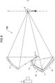
- 1 is a schematic cross-sectional view showing a first embodiment of a lighting device according to the present invention. It is a section schematic diagram showing a 2nd embodiment of an illuminating device concerning the present invention. It is the cross-sectional schematic which showed the structure which used the refracting mirror in 2nd Embodiment as the concave curved surface mirror, and used the 1st reflector as the plane mirror. It is the cross-sectional schematic which showed the structure which made the refracting mirror and 1st reflector in 2nd Embodiment into the concave curved surface mirror. It is a cross-sectional schematic diagram showing 3rd Embodiment of the illuminating device which concerns on this invention.
- FIG. 9 It is the cross-sectional schematic diagram showing 9th Embodiment when the 1st reflector of 6th Embodiment and a 2nd reflector are used for the illuminating device of 1st Embodiment. It is the figure which showed the optical path when the reflected light by a 1st reflector and a 2nd reflector was condensed on the back of a to-be-detected object.
- the first reflector and the second reflector of the sixth embodiment it will be described that the light quantity distribution can be controlled for each incident angle of the light beam directed to the detection object due to the difference in the surface curvature of each concave curved partial surface.
- the structure of the sorter is an optical detection unit including a pair of or one-side illumination devices that are placed before and after the object to be detected poured into an inclined chute from above and sandwiched along the flow path during the fall.
- the object to be detected is imaged by a camera (for example, a line sensor camera). After irradiating the detected object with light emitted from the illumination light source of the illuminating device, the reflected or transmitted light is imaged with a camera to obtain optical information of the detected object.
- an object to be detected that is sorted by a sorter is a rice grain.
- the harvested rice contains foreign substances such as defective rice and stones to a certain extent, so it is necessary to remove them, and the sorter uses the acquired optical information to meet the standards and other rice Sort into and.
- Detected objects determined to be out of the standard or foreign are transported to a different path from non-defective products by the force of air ejected from the ejector nozzle.
- the present invention is a technique particularly related to the lighting device in the configuration of the sorter.
- An illuminating device that is a means for irradiating light toward an object to be detected for discrimination by a sorter includes at least an illumination light source and a plurality of reflectors. In the following description, details of the configuration and functions other than the lighting device that are not directly related to the present invention are omitted.
- the illumination light source applied to the illumination device of the present embodiment is configured by arranging a plurality of LED chips on a substrate in a row or in a plane according to the width of the chute. LEDs may be mixed in a plurality of colors. In another embodiment, a light emitter other than the LED chip may be used.
- the plurality of reflectors used in this embodiment are concave curved mirrors, and elliptic concave concave mirrors having an elliptical curvature are used.
- the concave curved surface does not necessarily have an elliptical curvature, and may be a concave surface having a parabolic or hyperbolic curvature depending on a case where it is desired to weaken light collection on the object to be detected. Further, it may be a free-form surface that can freely set the incident angle of light directed toward the object to be detected, the light collecting position, and the light collecting condition.
- FIG. 1 is a schematic diagram of an illuminating device 100 according to the first embodiment, and shows what optical path the light emitted from the illumination light source 1 forms to illuminate the rice grain 2 that is the object to be detected. It is shown with a solid line.
- two reflectors 4 and 5 are arranged between the camera 3 and the rice grain 2 so as to sandwich the optical axis O connecting the camera 3 and the rice grain 2.
- the reflectors 4 and 5 are each a concave curved mirror.
- the concave curved mirror disposed below the optical axis O is referred to as a “first reflector 4”
- the concave curved mirror disposed above the optical axis O is referred to as a “second reflector 5”. This corresponds to the “first reflector” and the “second reflector” recited in the claims.
- the illumination light source 1 is disposed only on the second reflector 5 side. That is, the light beam group from the illumination light source 1 is incident on the first reflector 4 and the second reflector 5, and the illumination light source for each reflector does not exist independently. Therefore, a part of the light rays from the illumination light source 1 are reflected by the first reflector 4 and travel toward the rice grain 2, and another part of the light rays from the illumination light source 1 are reflected by the second reflector 5.
- the amount of light emitted from the illumination light source can be used effectively, and as a result, The number of illumination light sources can be simply reduced to half. Therefore, the cost required for the lighting device can be reduced.
- the illumination light source 1 shows the case where the illumination light source 1 is arranged on the second reflector 5 side above the optical axis O, the illumination light source 1 and the reflectors 4 and 5 are arranged symmetrically with respect to the optical axis O. It goes without saying that the same technical effect can be obtained even if the arrangement is reversed.
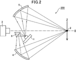
- the illumination device 200 according to the second embodiment further includes a refracting mirror 6 as shown in FIG. Since the functions of other components are the same as those in the first embodiment, the description thereof is omitted.
- the refracting mirror 6 in the present embodiment is a plane mirror, and is used to bend the optical path of the light emitted from the illumination light source 1 so that the light reaches the first reflector 4. Therefore, unlike the arrangement in the first embodiment, the illumination light source 1 is arranged between the first reflector 4 and the second reflector 5 as shown in FIG. The curved mirror) and the second reflector 5 are arranged so as to face each other. As shown in the drawing, a group of light rays from the illumination light source 1 does not directly enter the first reflector 4, but first, a part of the light beam group from the illumination light source 1 travels toward the refracting mirror 6, and this refraction. An optical path is formed in which the light reflected by the mirror 6 becomes incident light on the first reflector 4.
- the light beam of the illumination light source 1 can be directed to the rice grain 2 through a plurality of optical path bendings. . Further, the optical paths of all the light beams from the illumination light source 1 are not bent by the refracting mirror 6. As shown in FIG. 2, the light from the illumination light source 1 is directly incident on the second reflector 5 (for example, an elliptical concave curved mirror), and only the incident light of the first reflector is bent by the refracting mirror 6. . Note that the position of the refracting mirror 6 in FIG.
- the refractive mirror 6 may be disposed on the second reflector 5 side above the optical axis O.
- a part of the light beam from the illumination light source 1 enters the refracting mirror 6, and then the light beam bent by the refracting mirror 6 enters the first reflector 4.
- the position and orientation of the illumination light source 1, the refracting mirror 6, and the first and second reflectors 4 and 5 are adjusted so that the light beam from the illumination light source 1 is directly incident on the second reflector 5. .
- the optical axis O is adopted as the refracting mirror 6, but it does not necessarily have to be a plane mirror.
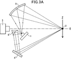
- the first reflector 4 ′ may be a plane mirror as shown in FIG. 3A, or the first reflector 4 may be a concave curved mirror as shown in FIG. 3B.
- the concave The curved mirror (or concave curved refracting mirror) is preferably an elliptic concave curved mirror.
- the concave curved mirror is preferably an elliptic concave curved mirror.
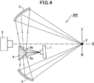
- the illumination device 300 of the third embodiment is characterized in that the refracting mirror 6 has a plurality of reflecting surfaces 6a and 6b. As shown in the drawing, a part of the light beam from the illumination light source 1 whose optical path is bent by the first reflecting surface 6a is reflected by the first reflector 4 which is a concave curved mirror (for example, an elliptical concave curved mirror). Later, the reflected light becomes illumination light from below the rice grain 2.
- the second reflector 5 which is a concave curved mirror (for example, an elliptic concave curved mirror).
- the reflected light becomes illumination light from above the rice grain 2. That is, the refracting mirror 6 in the second embodiment shown in FIG. 2 bends the light beam from the illumination light source 1 by a single reflecting surface so that the light beam is directed to the first reflector 4.
- the second reflecting surface 6b in addition to the first reflecting surface 6a having the same function as this, the second reflecting surface 6b also bends the light beam from the illumination light source 1, and this is bent into the first reflector 4.
- the second reflector 5 is directed to the second reflector 5.
- FIG. 4 shows an example in which the two reflecting surfaces of the refracting mirror 6 in the illuminating device 300 shown in FIG. 4 are constituted by refracting mirrors 6 ′ (reflecting surfaces 6 a ′ and 6 b ′) that are concave curved mirrors.
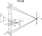
- FIG. 5A A further modification is shown in FIG.
- the two reflecting surfaces 6a 'and 6b' of the refracting mirror 6 ' are concave curved mirrors as in the case of FIG. 5A, but the first reflector 4 and the second reflector 5 are concave curved mirrors. Instead, the first reflector 4 ′ and the second reflector 5 ′, which are plane mirrors, are used. Also by this structure, the reflected light by two reflectors can illuminate the rice grain 2 from an up-down direction.
- the two reflecting surfaces 6a ′ and 6b ′ of the refracting mirror 6 ′ shown in FIG. 5A, the first reflector 4, and the second Each of the reflectors 5 preferably employs a parabolic concave curved mirror.
- the two reflecting surfaces 6a 'and 6b' of the refracting mirror 6 are elliptic concave curved mirrors.
- the refracting mirrors 6 and 6 ′ may be arranged so that a part or all of the refracting mirrors 6 and 6 ′ are present on the second reflectors 5 and 5 ′ above the optical axis O. This is the same as in the second embodiment. Further, even if the optical source O, the refracting mirrors 6 and 6 ', the first reflectors 4 and 4', and the second reflectors 5 and 5 'are reversed, the same technical relationship is obtained. The effect is the same as in the above-described embodiment.
- the illumination device 400 of the fourth embodiment is characterized in that the refractive mirror 6 and the first reflector 4 of the second embodiment shown in FIG. 2 are integrated.
- the reflection partial surface 7c of the first reflector 7 shown in FIG. 6 corresponds to the refractive mirror 6 in the second embodiment
- the reflection partial surface 7a is the second embodiment.
- the other components are the same as those in the first to third embodiments, and thus description thereof is omitted.
- the light beam from the illumination light source 1 toward the reflection partial surface 7c of the first reflector 7 is reflected to change the optical path toward the reflection partial surface 7a. Further, the light beam reflected by the reflection partial surface 7a travels toward the rice grain 2 and becomes illumination light from below the rice grain 2. Note that at least a part of the light beam group not directed to the reflection partial surface 7c is directly incident on the second reflector 5, and the reflected light beam becomes illumination light from above the rice grain 2 as in the second embodiment. The same.
- the first reflector 7 may be arranged so that a part or all of the first reflector 7 exists on the second reflector 5 side above the optical axis O. This is the same as in the above-described embodiment. Further, the same technical effect is obtained in the arrangement relationship in which the illumination light source 1, the first reflector 7, and the second reflector 5 are reversed symmetrically with respect to the optical axis O as in the above-described embodiment.
- the illumination device 500 of the fifth embodiment is characterized in that the refracting mirror 6 and the first reflector 4 of the third embodiment shown in FIG. 4 are integrated.
- the reflection partial surfaces 8b and 8c of the first reflector 8 shown in FIG. 7 are the refraction mirror 6 having the first reflection surfaces 6a and 6b in the third embodiment.
- the reflection partial surface 8a corresponds to the first reflector 4 in the third embodiment.
- the other components are the same as those in the other embodiments, and the description thereof is omitted.
- FIGS. 5 (A) and 5 (B) which are application examples of the third embodiment, are integrated, Needless to say, it is included as an application example of the fifth embodiment.
- the light beam from the illumination light source 1 toward the reflection partial surface 8b of the first reflector 8 is reflected to change the optical path toward the reflection partial surface 8a. Further, the light beam reflected by the reflection partial surface 8a travels toward the rice grain 2 and becomes illumination light from below the rice grain 2. In addition, a part of the light beam from the illumination light source 1 is reflected by the reflection partial surface 8c and the optical path is changed so as to go to the second reflector 5, and the reflected light beam becomes the illumination light from above the rice grain 2. This is the same as the third embodiment.
- the same technical effect is obtained in the arrangement relationship in which the illumination light source 1, the first reflector 8, and the second reflector 5 are reversed with the optical axis O symmetrical, as in the above-described embodiment.
- the first reflector 8 may be arranged such that a part or the whole of the first reflector 8 exists on the second reflector 5 side above the optical axis O. This is the same as in the above-described embodiment.
- a refracting mirror for distributing a group of rays from the illumination light source 1 to a plurality of reflectors arranged above or below the optical axis O of the camera, Only the aspect which focused on the point which makes a reflector an integral structure was demonstrated. Therefore, as in the second and third embodiments, the reflecting partial surfaces 7c, 8b, and 8c having the same function as the refracting mirror 6 or 6 'include not only a plane mirror but also a concave mirror shape. . Furthermore, it should be noted that the reflecting partial surfaces 7a and 8a and the second reflector 5 having the same function as the first reflector 4 or 4 'include both a plane mirror and a concave curved mirror.
- first reflectors 7 and 8 may be arranged so that part or all of the first reflectors 7 and 8 exist on the second reflector 5 or 5 ′ side above the optical axis O.
- the illumination light source 1, the first reflectors 7 and 8, and the second reflector 5 may be reversed with the optical axis O symmetrical.
- one illumination light source 1 is used for simultaneously illuminating the upper half and the lower half of one front and rear side of the rice grain 2. Functions as a common light source. For this reason, the light quantity which one illumination light source radiates
- the illumination light source 1 is not located outside the reflector as in the first embodiment, but is disposed between (inside) the two reflectors, so that the sorter can be compared with the first embodiment. This is an effective configuration for realizing further downsizing of the whole.
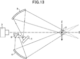
- the sorter moves the rice grains 2 that fall from the chute and move along the fall trajectory Z by the two cameras 3 (front camera 3a and rear camera 3b) that are line sensor cameras. Take an image from the side.
- the rice grains 2 jumped on the chute among a large number of rice grains, so that the ideal detection position P where the optical axis O of the front camera 3a and the fall trajectory Z intersect, Rice may be imaged at a detection position P ′ close to the front camera 3a side and a detection position P ′′ close to the rear camera 3b side (see FIG. 8).
- the surface is regarded as the center of the rice grain, and the falling locus Z of the center of the rice grain is illustrated, where 9a and 9b are backgrounds for the cameras facing each other.
- the light ray group from the illumination light source is focused on the object surface of the rice grain 2 by focusing on the assumption that the ideal detection position P matches the object surface of the rice grain 2, that is, the center of the rice grain. For this reason, in the imaging of the front side of the rice grain by the front camera 3a, when the degree of deviation toward the camera 3a is large, the object plane that is not on the optical path of the light group from the lower direction by the first reflector 4 is similarly used. The object surface which is not on the optical path of the light ray group from the upper direction by the reflector 5 is generated. For example, the rice grain 2 approaching P ′ shown in FIG. In some cases, the rice grains may come close to P ′′ on the rear camera 3b side.
- the rice grains will still have no object surface on the optical path of the light beam reflected by the reflector. Note that the above-mentioned problem in the imaging of the front side of rice grains by the front camera 3a applies to the imaging of the rear side of rice grains by the rear camera 3b.
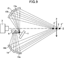
- the sixth object shown in FIG. 9 has been devised in order to solve the influence on the detected image caused by the deviation of the position of the object surface based on such a thing that the object to be detected falls while jumping on the chute. It is an embodiment.
- the 1st reflector 14 and the 2nd reflector 15 in the illuminating device of 6th Embodiment have several concave-curved partial surfaces (for example, two elliptical concave curved surfaces) from which curvature differs.
- the plurality of concave partial surfaces are at least a first concave partial surface defined by a first curvature and a second concave partial surface defined by a second curvature different from the first curvature. It is comprised including. Since the other components are the same as those in the first embodiment, the effect of the concave curved mirror having “a plurality of concave curved partial surfaces” will be described below.
- the use of reflectors 14 and 15 having a plurality of concavely curved partial surfaces is characterized in that a width is generated in the condensed region.
- the first reflector 14 includes a first concave portion surface 14a and a second concave portion surface 14b.
- the 2nd reflector 15 contains the 1st concave-curved partial surface 15a and the 2nd concave-curved partial surface 15b.
- Both the first concave portion surface 14a and the second concave portion surface 14b of the first reflector 14 reflect the light from the illumination light source 1 to illuminate the rice grain 2 from below, but the first concave portion
- the condensing position of the reflected light by the partial surface 14a is not the same as the condensing position of the reflected light by the second concave curved partial surface 14b. This is because the surface curvature that defines the first concave portion surface 14a is different from the curvature that defines the second concave portion surface 14b.
- the ideal detection position P of the rice grain 2 (in FIG.
- the surface curvature of the first concave partial surface 14a is designed so as to collect light over a predetermined range (in the direction away from 3).
- the group of light beams reflected by the first concave portion surface 14b is condensed over a predetermined range forward (in the direction approaching the camera 3 in FIG. 9) from the ideal detection position P of the rice grain 2.
- the surface curvature of the first concave curved partial surface 14b is designed in advance.
- each group of rays reflected by the first concave part surface 15a and the second concave part surface 15b of the second reflector 15 is the ideal of the rice grain 2.
- the surface curvature of the second reflector 15 is designed so as to collect light over a predetermined range from the detection position P to the rear or front.
- FIG. 9 shows a case where the illumination range by the first concavely curved partial surface 14a and the illumination range by the second concavely curved partial surface 14b do not overlap, but they may partially overlap.
- a part of the surface may be illuminated with reflected light from two concave curved partial surfaces.
- the light beam reflected by the first concave portion surface 14a is condensed over a predetermined range from the ideal detection position P of the rice grain 2 and reflected by the first concave portion surface 14b.
- the group may collect light over a predetermined range behind the ideal detection position P of the rice grain 2. This depends on the surface curvature of each concave curved partial surface. The same applies to the first concave portion surface 15a and the second concave portion surface 15b.
- FIG. 9 shows only the front camera 3a side of FIG. 8, but the illumination for the entire rear half of each rice grain by the rear camera 3b is exactly the same, and is omitted.
- the concept of condensing position control using the first and second reflectors 24 and 25 is basically the same as in the sixth embodiment.
- the surface shape of the first and second reflectors 14 and 15 in the sixth embodiment is a concave curved surface shape in which a plurality of concave curved surface surfaces having different curvatures are combined.
- the condensing position is designed to be before and after the rice grain
- the first and second reflectors 24 and 25 of the seventh embodiment have a free concave curved surface shape that forms one concave curved surface.
- the condensing region is made wide by the curvature at an arbitrary position on the free concave curved surface.
- the concept of condensing position control using the first and second reflectors 34 and 35 is basically the same as that of the sixth embodiment.
- the surface shape of the first and second reflectors 14 and 15 in the sixth embodiment is a concave curved surface shape in which a plurality of concave curved surface surfaces having different curvatures are combined.
- the condensing position is designed to be before and after the rice grain, but the concave curved surface has a mirror surface shape approximated by a plurality of planes. The feature is that it creates a width in the region where light is condensed.
- FIG. 12 shows the optical path of the light source.
- the 2nd reflector 5 in FIG. 3 (A) which is an application example of 2nd Embodiment, 1st and 2nd reflectors 4 and 5 in FIG. 3 (B), 3rd Embodiment
- the present invention can also be applied to the first and second reflectors 4 and 5 in the configuration shown in FIG. 4 and the application example shown in FIG. 5A.
- the curvature that defines the surface shape of each reflector when the first reflectors 14, 24, 34 and the second reflectors 15, 25, 35 are used, the curvature that defines the surface shape of each reflector.
- the illuminating apparatus of the sixth to ninth embodiments This eliminates the problem that the detected image becomes dark or a shadow is generated even if the position of the surface of each rice grain is slightly shifted. Thereby, it is possible to manufacture a sorter in which the detection accuracy does not decrease.
- the reflector defined by the concave curved surface described in the embodiments other than the sixth to ninth embodiments is used, for example, as shown in FIG.
- the reflectors according to the sixth to ninth embodiments an excellent effect is obtained in that the light quantity distribution can be controlled for each incident angle of the light beam directed to the detection object.
- the reflector defined by the concave curved surface shown in the sixth to ninth embodiments is used, the light quantity distribution is appropriately controlled even when the detected object does not fall on the assumed ideal locus.
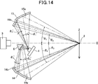
- FIG. 14 is a graph in which the surface area ratio of the first concave curved portion surfaces 14a and 15a and the second concave curved portion surfaces 14b and 15b shown in FIG.
- the light from the illumination light source reflected from the first concave partial surfaces 14 a and 15 a far from the optical axis O has a large incident angle ( ⁇ 1 , ⁇ 4 ) and is a rice grain 2 that is a detected portion. Irradiate.
- the light from the illumination light source that has reflected the second concave partial surfaces 14b and 15b closer to the optical axis O irradiates the rice grain 2 with a small incident angle ( ⁇ 2 , ⁇ 3 ).
- a small incident angle ⁇ 2 , ⁇ 3
- a large shadow appears on the detected image around the outline of the detection object. It has been found from the experimental results by the applicant.
- the light emitted from the illumination light source light reflects the first concave partial surfaces 14a and 15a far from the optical axis O at larger radiation angles ( ⁇ 1 ′, ⁇ 4 ′), thereby detecting the object to be detected. It is possible to reduce the shadow around the outline of the.
- a detection image having a shadow around the contour of the detection object in particular, the upper contour portion and the lower contour portion
- the use of such a reflector has a remarkable effect.
- the reflector is defined by two concave curved surfaces (a first concave curved surface and a second concave curved surface).
- the present invention is not limited to this. Furthermore, you may make it have many concave curved surfaces, for example, comprising the whole concave curved surface by three concave curved partial surfaces.
- the amount of light reflected from the first concave part surface 14a, 15a in FIG. 14 is reflected from each of the second concave part surface 14b, 15b.
- a mode in which a plurality of lines are added to at least one of the concave curved surfaces of the first reflector or the second reflector described so far will be described.
- a camera for example, a line sensor camera
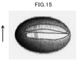
- the light emitting surface of the illumination light source may be reflected (dotted line in FIG. 15). (See the part surrounded by).
- an illumination light source is configured with a plurality of LED chips as light emitters
- the presence of a plurality of light emitters arranged on the surface of the object to be detected appears so that the reflected light is weighted to the original illumination light. Will be.
- the camera receives the light. It is. A glossy object to be detected is particularly affected by this. In order to increase the detection accuracy, it is necessary to prevent the LED chip from appearing on the surface of the object to be detected.
- the concave curved surface of the first reflector or the second reflector is bent into a concave curved surface so that the streaks in the rolling direction are vertical streaks of aluminum rolling material, and the concave curved mirror is provided.
- a concave curved mirror is formed by vertically adding innumerable fine streaks (see FIG. 16) such as hairline processing to a mirror-finished aluminum plate and then bending the concave curved surface.
- the first reflector or the second reflector is manufactured by resin molding, vertical bars are provided on the mold so that vertical grooves are formed on the reflective surface of the concave curved surface, and aluminum is applied to the surface having the vertical bars.
- a concave curved mirror may be formed by vapor deposition.
- the presence of vertical streaks on the concave surface of the first reflector or the second reflector creates the effect that the light from the illumination light source is laterally confused after reflecting each concave curved mirror.
- the reflection of the LED chip light emitting surface on the surface of the object to be detected is dispersed in the horizontal direction.
- the light from the illumination light source reflects each concave curved mirror and creates an effect of confusion not only in the horizontal direction but also in the vertical direction. .
- the reflection of the LED chip light emitting surface on the surface of the object to be detected is dispersed horizontally and vertically. In this case, the amount of light directed toward the object to be detected is significantly reduced. However, when the amount of light from the LED is sufficient, the effect is extremely great as a means for avoiding the reflection of the LED chip.
- the illumination light source may use any light emitter.
- the conventional lighting device uses many LED chips, and lights up using many drive circuits according to the LED chips, thereby detecting LED breakage. Had gone. Therefore, many costs are required for the LED chip and the LED drive circuit. Or although it was possible to reduce the LED driving circuit and reduce the cost by lighting the LED chip with a parallel circuit, there was a problem that it was not possible to detect the LED ball breakage.
- one illumination light source can be used together for upper and lower illuminations, not only the illumination light source but also the LED chip can be simply reduced to a half, and the LED drive circuit can also be reduced. As a result, it is possible to detect LED bulb breakage while reducing costs.
- the illumination light to the object to be detected is more than twice that of a conventional illumination device that does not use a reflector. It is possible to replace a part of the illumination light source with another wavelength LED such as an IR-LED, and the same illumination device can irradiate light of a plurality of wavelengths. In any case, the amount of light more than that of the conventional lighting device can be obtained with a small number of chips, so that the cost reduction effect when using an IR-LED that is more expensive than a white LED is very large.
Landscapes
- Life Sciences & Earth Sciences (AREA)
- General Physics & Mathematics (AREA)
- Health & Medical Sciences (AREA)
- Chemical & Material Sciences (AREA)
- Physics & Mathematics (AREA)
- Immunology (AREA)
- General Health & Medical Sciences (AREA)
- Biochemistry (AREA)
- Analytical Chemistry (AREA)
- Pathology (AREA)
- Engineering & Computer Science (AREA)
- General Engineering & Computer Science (AREA)
- Botany (AREA)
- Wood Science & Technology (AREA)
- Food Science & Technology (AREA)
- Medicinal Chemistry (AREA)
- Spectroscopy & Molecular Physics (AREA)
- Investigating Materials By The Use Of Optical Means Adapted For Particular Applications (AREA)
- Sorting Of Articles (AREA)
Abstract
Description
上記引用文献1と同様に、選別機の構造は、被検出物を上方から傾斜シュートに流し込み落下させ、落下途中で流下軌跡を挟んで前後に設置した一対又は片側の照明装置を含む光学検出部によって被検出物をカメラ(例えば、ラインセンサカメラ)で撮像する。照明装置の照明光源から発した光を被検出物に照射後、反射若しくは透過した光をカメラで撮像することで、被検出物の光学的情報を取得する。以下の実施形態において、選別機により選別される被検出物は米粒とする。収穫される米には、不良米や石などの異物が一定程度含まれているためこれらを除去する必要があり、選別機は取得した光学的情報に基づき、基準を満たす米とそれ以外のものとに分別する。
本実施形態の照明装置に適用する照明光源は、シュートの幅に応じて基板上にLEDチップを1列若しくは平面的に複数個配列して構成する。LEDは複数色を混在してもよい。なお、別の実施形態においては、LEDチップ以外の発光体を用いてもよい。
図1に示すように、カメラ3と米粒2の間であって、カメラ3と米粒2を結ぶ光軸Oを挟むように2つのリフレクタ4,5を配置する。上述したように、本実施形態の場合、リフレクタ4,5は各々凹曲面鏡である。ここでは、便宜上、光軸Oの下方に配置する凹曲面鏡を「第1のリフレクタ4」、光軸Oの上方に配置する凹曲面鏡を「第2のリフレクタ5」とする。これは、特許請求の範囲に記載する「第1のリフレクタ」及び「第2のリフレクタ」に対応する。
したがって、照明光源1からの一部の光線が第1のリフレクタ4によって反射されて米粒2へ向かって進むとともに、照明光源1からの別の一部の光線が第2のリフレクタ5によって反射されて米粒2へ向かう。つまり、図1に示す本実施形態の場合、第2のリフレクタ5によって反射された光は米粒2の前側上半分を、第1のリフレクタ4によって反射された光は米粒2の前側下半分を照らすことになる。なお、図1は、米粒2の前側の照明についてのみを示しており、米粒2の後側を照明するには、同様の照明装置を米粒2の流下軌跡Zを挟んで後側に配置すればよい。
第2の実施形態の照明装置200は、図2に示すように屈折鏡6を更に備える。他の構成要素の機能については第1の実施形態と同じであるため説明は省略する。
また、照明光源1からの光線群すべての光路が、屈折鏡6により曲げられるというわけではない。図2に示すとおり、第2のリフレクタ5(例えば、楕円凹曲面鏡)へは照明光源1からの光線が直接入射し、屈折鏡6で折り曲げられるのは第1のリフレクタの入射光のみである。なお、図2の屈折鏡6の位置は光軸Oよりも下方であって第1のリフレクタ4に近い場所に配置しているが、照明光源1の光線放射の方向や屈折鏡6の傾きの関係によっては、光軸Oより上方の第2のリフレクタ5側に屈折鏡6の一部又は全部を配置することもあり得る。
さらに、本実施形態の場合、屈折鏡6として平面鏡を採用したが、必ずしも平面鏡でなければならないというわけではない。平面鏡を使用したときと同じように照明光源1からの光線群を分離させ、第1のリフレクタ4及び第2のリフレクタ5が存在する各方向に向かわせることが可能な凹曲面形状の屈折鏡6’を採用してもよい。この場合、図3(A)のように平面鏡の第1のリフレクタ4’であってもよいし、或いは図3(B)のように凹曲面鏡の第1のリフレクタ4であってもよい。
第3の実施形態の照明装置300は図4に示すように、屈折鏡6が複数の反射面6a,6bを有することが特徴である。図示するように、第1の反射面6aで光路が折曲げられた照明光源1からの一部の光線が凹曲面鏡(例えば、楕円凹曲面鏡)である第1のリフレクタ4によって反射された後、その反射光線は米粒2の下方向からの照明光となる。同様に、第1の反射面6bで光路が折曲げられた照明光源1からの一部の光線が、凹曲面鏡(例えば、楕円凹曲面鏡)である第2のリフレクタ5によって反射された後、その反射光線は米粒2の上方向からの照明光となる。
つまり、図2に示す第2の実施形態における屈折鏡6は単一の反射面によって照明光源1からの光線を折り曲げて第1のリフレクタ4へ光線が向かうようにしているのに対し、第3の実施形態の屈折鏡6はこれと同様の機能を有する第1の反射面6aの他に、第2の反射面6bによっても照明光源1からの光線を折り曲げて、これを第1のリフレクタ4の他に、第2のリフレクタ5へと向かわせる構造である。
第4の実施形態の照明装置400は、図6に示すように、図2に示す第2の実施形態の屈折鏡6と第1のリフレクタ4を一体構造にした点が特徴である。第2の実施形態と対比して説明すると、図6に示す第1のリフレクタ7の反射部分面7cが第2の実施形態における屈折鏡6に相当し、反射部分面7aが第2の実施形態における第1のリフレクタ4に相当する。なお、他の構成要素については第1~第3の実施形態と同じであるため説明は省略する。
第5の実施形態の照明装置500は、図7に示すように、図4に示す第3の実施形態の屈折鏡6と第1のリフレクタ4を一体構造にした点が特徴である。第3の実施形態と対比して説明すると、図7に示す第1のリフレクタ8の反射部分面8b、8cが、第3の実施形態における第1の反射面6a、6bを有する屈折鏡6に相当し、反射部分面8aが第3の実施形態における第1のリフレクタ4に相当する。なお、他の構成要素については他の実施形態と同じであるため説明は省略する。なお、図示はしないが、第3の実施形態の応用例である図5(A)及び図5(B)における屈折鏡6’と第1のリフレクタ4又は4’を一体構造にした場合も、第5の実施形態の応用例として含まれることはいうまでもない。
また、照明光源1は、第1の実施形態のようなリフレクタの外側に存在するのではなく、2つのリフレクタの間(内部)に配置するので、第1の実施形態と比較しても選別機全体のより一層の小型化の実現に有効な構成となる。
次に、上述した第1のリフレクタ又は第2のリフレクタに凹曲面鏡を使用する場合であり、その凹曲面形状が1箇所に光を集光させず、集光位置を前後に分散させるケースを説明する。そのような鏡面形状は、上記実施形態における第1及び第2の凹曲面鏡4,5のみならず、リフレクタ7,8の反射部分面7a,8aにも適用され得る。
以下では、説明の便宜上、第2の実施形態で示した照明装置200の構成に適用した場合を説明することにする。
なお、米粒がリアカメラ3b側のP”に寄ってしまう場合もあるが、ズレの程度が大きければやはりリフレクタで反射された光線群の光路上に物体面がない米粒となり、その米粒に光があたらない。なお、リアカメラ3bによる米粒後側の撮像については、フロントカメラ3aによる米粒前側の撮像における上記問題が同様にあてはまる。
第1の凹曲部分面15aと第2の凹曲部分面15bについても同様である。
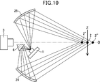
図10に示す第7の実施形態において、第1及び第2のリフレクタ24,25を用いた集光位置のコントロールの考え方は、基本的に第6の実施形態と同じである。異なる点は、第6の実施形態における第1及び第2のリフレクタ14,15の面形状が、曲率の異なる複数の凹曲部分面を組み合わせた凹曲面形状であり、各凹曲部分面ごとに集光位置が米粒の前後になるよう設計してあるのに対し、第7の実施形態の第1及び第2のリフレクタ24,25の場合は、1つの凹曲面を形成する自由凹曲面形状であり、その自由凹曲面上の任意の位置の曲率によって集光領域に幅を生み出しているのが特徴である。
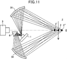
図11に示す第8の実施形態において、第1及び第2のリフレクタ34,35を用いた集光位置のコントロールの考え方は、基本的に第6の実施形態と同じである。異なる点は、第6の実施形態における第1及び第2のリフレクタ14,15の面形状が、曲率の異なる複数の凹曲部分面を組み合わせた凹曲面形状であり、各凹曲部分面ごとに集光位置が米粒の前後になるよう設計してあるのに対し、第8の実施形態の第1及び第2のリフレクタ34,35の場合は、凹曲面を複数の平面で近似した鏡面形状にすることによって集光される領域に幅を生み出しているのが特徴である。
第6の実施形態における第1及び第2のリフレクタ14,15(曲率の異なる複数の凹曲部分面があるリフレクタ)の技術思想を、第1の実施形態の照明装置に用いたときの照明用光源の光路を示したのが図12である。また、図示しないが、第2の実施形態の応用例である図3(A)における第2のリフレクタ5、図3(B)における第1及び第2のリフレクタ4,5、第3の実施形態である図4及びその応用例である図5(A)に示す構成における第1及び第2のリフレクタ4,5にも適用可能であることは言うまでもない。
一方で、第6の実施形態~第9の実施形態のリフレクタの場合は、被検出物に向かう光線の入射角ごとに光量配分を制御できるという優れた効果が生じる。
図14に示すように、光軸Oから遠い第1の凹曲部分面14a,15aを反射した照明光源からの光が、大きな入射角(θ1,θ4)で被検出部である米粒2を照射する。また、光軸Oにより近い第2の凹曲部分面14b,15bを反射した照明光源からの光は、小さな入射角(θ2,θ3)で米粒2を照射する。特に、米粒のような物体とは異なり、光を透過させない被検出物の場合、入射角度の小さな光源光が照射されると、その検出画像には被検出物の輪郭周辺に大きな影が出てしまうことが、本出願人による実験結果でも判明している。
そこで、照明光源光から放射される光が、より大きな放射角(θ1’,θ4’)で光軸Oから遠い第1の凹曲部分面14a,15aを反射することにより、被検出物の輪郭周辺の影を少なくすることができる。被検出物の輪郭周辺(特に、上輪郭部分及び下輪郭部分)に影がある検出画像が取得されるという特殊な事情があるとき、このようなリフレクタを使用すると顕著な効果を呈する。
また、上下輪郭部に影が大きく出ない被検出物であれば、図14における第1の凹曲部分面14a,15aを反射する光量を、第2の凹曲部分面14b,15bそれぞれから反射する光量と同等または少なくするようθ1,θ2,θ3,θ4,θ1’,θ2’,θ3’,θ4’を設定し、これに対応する表面積の凹曲面を形成してよい。
次に、これまで述べてきた第1のリフレクタ又は第2のリフレクタの少なくとも何れか一つの凹曲面に、複数の筋が追加された態様を説明する。
表面が曲率を持ち且つ光沢のある被検出物をカメラ(例えば、ラインセンサカメラ)で撮像して検出画像を得た場合、照明光源の発光面が写り込んでしまうことがある(図15の点線で囲った部分を参照)。例えば、複数のLEDチップを発光体として照明光源を構成した場合、被検出物の表面に複数の並んだ発光体の存在が識別できるように写ってしまい、写り込み光が本来の照明光に加重されてしまう。これは、照明光源の光が第1及び第2のリフレクタにより反射された後、表面が曲率をもつ被検出物の特定の場所で正反射されると、カメラがその光を受光してしまうからである。光沢のある被検出物は特にこの影響が大きい。検出精度を上げるには、被検出物の表面にLEDチップが写り込むことを回避する必要がある。
また、筋に代わり、縦横比を任意に設定したディンプル(凹み)を形成することで、照明光源からの光が各凹曲面鏡を反射後に横方向のみならず縦方向にも錯乱させる効果を生み出す。これにより、被検出物表面へのLEDチップ発光面の写り込みは横及び縦方向に分散する。この場合、被検出物へ向かう光量は著しく低下するが、LEDの光量が十分にある場合は、LEDチップの写り込みを回避する手段としては効果が非常に大きいものとなる。
本発明によれば1つの照明光源が上下の照明用に併用できるため、照明光源のみならずLEDチップを単純に2分の1に削減でき、LED駆動回路も減らすことができる。その結果、コストを下げながらLED球切れ検知を実現することができる。
上述してきた実施形態においては、米粒を対象とした選別機の例を説明したが、必ずしもこれに限定するわけではない。例えば、米以外の大豆等の穀粒やコーヒー豆や種などの粒型固体はもちろんのこと、茶葉やタブレット、さらには自動車のバンパーなどの合成樹脂はリサイクル工程でペレット状に加工されるが、色塗料を含む樹脂ペレットを本願発明の選別機による選別の対象として用いることができる。
さらにまた、被検出物が米粒などの粒型の対象物ではなく、例えばコンベア上に積置したシート若しくはフィルム状の対象物である場合は、そのシート状等の対象物を鉛直方向からカメラによって観察し、シート状の対象物内で異物を検出するとコンベア上の搬路変更手段が駆動して、異物を含んだシート状の対象物のみが規格外対象物用の貯留ケースに搬送されるようにすることが可能である。
2,2’,2” 米粒
3,3a,3b カメラ
4,4’ 第1のリフレクタ
5,5’ 第2のリフレクタ
6,6’ 屈折鏡
6a,6a’ 第1の反射面
6b,6b’ 第2の反射面
7 第1のリフレクタ
7a,7b,7c 反射部分面
8 第1のリフレクタ
8a,8b,8c 反射部分面
9a,9b バックグランド
14,24,34 第1のリフレクタ
15,25,35 第2のリフレクタ
14a,15a 第1の凹曲部分面
14b,15b 第2の凹曲部分面
Z 被検出物の落下軌跡
O 光軸
P 理想的な検出位置
P’ フロントカメラ3a側に寄った検出位置
P” リアカメラ3b側に寄った検出位置
Claims (13)
- 光学検出手段による被検出物の検出画像に基づき、当該被検出物が良品であるか又は不良品であるかを区別する選別機又は検査機に用いられる照明装置であって、
照明光を発光する光源を有する光源部と、
前記光源部からの光線を前記被検出物に向けて反射する複数のリフレクタと、
を備えたことを特徴とする、選別機又は検査機用照明装置。 - 前記複数のリフレクタは、前記光学検出手段の光軸を挟んで配置される第1のリフレクタ及び第2のリフレクタを含み、前記第1のリフレクタ及び前記第2のリフレクタの少なくとも何れかは凹曲面鏡である、請求項1に記載の選別機又は検査機用照明装置。
- 同一の前記光源部からの光線が前記第1のリフレクタ及び前記第2のリフレクタにより反射されて前記被検出物に向かう光路をとることで前記被検出物を上下方向から照明する、請求項2に記載の選別機又は検査機用照明装置。
- 前記光源部は、前記第1のリフレクタと前記第2のリフレクタとの間の前記光軸を含む空間領域に配置される、請求項2又は3に記載の選別機又は検査機用照明装置。
- 前記光源部から放射された光線のうちの少なくとも一部の光線の光路上に屈折鏡を配置し、
前記屈折鏡の第1の反射面は、前記少なくとも一部の光線の光路を折り曲げて前記第1のリフレクタに向けて進ませ、前記光源部から放射された光線のうち、前記屈折鏡に到達しない光線の少なくとも一部が前記第2のリフレクタに入射する、請求項4に記載の選別機又は検査機用照明装置。 - 前記光源部から放射された光線の光路上に屈折鏡を配置し、
前記屈折鏡は、第1の反射面と、前記第1の反射面とは異なる方向に光路を変える第2の反射面とを有し、
前記第1の反射面は、前記光源部から放射された光線の一部の光路を折り曲げて前記第1のリフレクタに向かうよう反射させ、
前記第2の反射面は、前記1の反射面に到達しない前記光源部からの光線の少なくとも一部を前記第2のリフレクタに向かうよう反射させる、請求項4に記載の選別機又は検査機用照明装置。 - 前記凹曲面鏡は、第1の曲率により規定される第1の凹曲部分面と、前記第1の曲率とは異なる第2の曲率により規定される第2の凹曲部分面とを有し、凹曲面全体が前記第1の凹曲部分面と前記第2の凹曲部分面で構成される凹面形状である、請求項2~6の何れか1項に記載の選別機又は検査機用照明装置。
- 前記凹曲面鏡は、局所的な曲率半径が凹曲面上の位置や方位によって連続的に変化する自由凹曲面鏡である、請求項2~6の何れか1項に記載の選別機又は検査機用照明装置。
- 前記凹曲面鏡は、凹曲面が平面で近似された凹曲面鏡である、請求項2~6の何れか1項に記載の選別機又は検査機用照明装置。
- 前記第1のリフレクタ及び第2のリフレクタの少なくとも1つは、凹曲面の縦方向に沿って複数の溝が重なるよう加工されている面形状を有する、請求項2~9の何れか1項に記載の選別機又は検査機用照明装置。
- 光学検出手段による被検出物の検出画像に基づき、当該被検出物が良品であるか又は不良品であるかを区別する選別機又は検査機に用いられる照明装置であって、
照明光を発光する光源を有する光源部と、
前記光源部からの光線を前記被検出物に向けて反射する複数のリフレクタであって、前記光学検出手段の光軸を挟んで配置される第1のリフレクタ及び第2のリフレクタを含み、前記第1のリフレクタ及び前記第2のリフレクタは平面鏡である前記複数のリフレクタと、
を備えたことを特徴とする選別機又は検査機用照明装置。 - 前記光源部から放射された光線のうちの少なくとも一部の光線の光路上に配置した屈折鏡であって、第1の凹曲反射面及び第2の凹曲反射面をもつ前記屈折鏡を更に備え、
前記第1の凹曲反射面は、前記光源部から放射された光線の少なくとも一部の光路を折り曲げて前記第1のリフレクタに向かうよう反射させ、前記第2の凹曲反射面は、前記1の凹曲反射面に到達しない前記光線の少なくとも一部を前記第2のリフレクタに向かうよう反射させ、これにより、前記第1のリフレクタ及び前記第2のリフレクタにより反射された前記光線が前記被検出物に向かう光路をとることで前記被検出物を上下方向から照明する、請求項11に記載の選別機又は検査機用照明装置。 - 前記第1のリフレクタ及び前記屈折鏡が単一構造の鏡体である、請求項5~12の何れか1項に記載の選別機又は検査機用照明装置。
Priority Applications (6)
| Application Number | Priority Date | Filing Date | Title |
|---|---|---|---|
| KR1020207025271A KR20200123147A (ko) | 2018-02-26 | 2019-02-26 | 선별기 또는 검사기용 조명 장치 |
| US16/975,277 US20210003509A1 (en) | 2018-02-26 | 2019-02-26 | Illuminating device for a sorting or inspecting machine |
| BR112020017021-6A BR112020017021A2 (pt) | 2018-02-26 | 2019-02-26 | Dispositivo de iluminação usado para uma máquina de classificação ou uma máquina de inspeção |
| EP19757866.9A EP3761011A4 (en) | 2018-02-26 | 2019-02-26 | SORTING MACHINE OR INSPECTION MACHINE LIGHTING DEVICE |
| AU2019224509A AU2019224509A1 (en) | 2018-02-26 | 2019-02-26 | Illuminating device for sorting machine or inspecting machine |
| CN201980014684.1A CN111742213A (zh) | 2018-02-26 | 2019-02-26 | 用于分选机或检查机的照明装置 |
Applications Claiming Priority (2)
| Application Number | Priority Date | Filing Date | Title |
|---|---|---|---|
| JP2018-031560 | 2018-02-26 | ||
| JP2018031560A JP6909407B2 (ja) | 2018-02-26 | 2018-02-26 | 選別機又は検査機用照明装置 |
Publications (1)
| Publication Number | Publication Date |
|---|---|
| WO2019164009A1 true WO2019164009A1 (ja) | 2019-08-29 |
Family
ID=67688133
Family Applications (1)
| Application Number | Title | Priority Date | Filing Date |
|---|---|---|---|
| PCT/JP2019/007217 Ceased WO2019164009A1 (ja) | 2018-02-26 | 2019-02-26 | 選別機又は検査機用照明装置 |
Country Status (9)
| Country | Link |
|---|---|
| US (1) | US20210003509A1 (ja) |
| EP (1) | EP3761011A4 (ja) |
| JP (1) | JP6909407B2 (ja) |
| KR (1) | KR20200123147A (ja) |
| CN (1) | CN111742213A (ja) |
| AU (1) | AU2019224509A1 (ja) |
| BR (1) | BR112020017021A2 (ja) |
| TW (1) | TWI719410B (ja) |
| WO (1) | WO2019164009A1 (ja) |
Cited By (1)
| Publication number | Priority date | Publication date | Assignee | Title |
|---|---|---|---|---|
| CN112816718A (zh) * | 2019-11-15 | 2021-05-18 | 豪夫迈·罗氏有限公司 | 用于确定实验室样品容器性质的设备、方法和自动化系统 |
Families Citing this family (5)
| Publication number | Priority date | Publication date | Assignee | Title |
|---|---|---|---|---|
| JP6909407B2 (ja) * | 2018-02-26 | 2021-07-28 | 株式会社サタケ | 選別機又は検査機用照明装置 |
| SE544932C2 (en) * | 2021-05-31 | 2023-01-10 | Bomill Ab | Object sorting device comprising an illumination unit and pivotable mirrors |
| JP7440044B2 (ja) * | 2022-02-08 | 2024-02-28 | ユーシーシー上島珈琲株式会社 | コーヒー豆類の良品識別機能を備える良品検査システムおよび良品検査方法 |
| EP4246131A1 (en) * | 2022-03-14 | 2023-09-20 | Bühler UK Limited | Lighting for an optical monitoring apparatus |
| KR102935628B1 (ko) | 2023-09-22 | 2026-03-09 | (주)아이씨디 | 반사광학계를 이용한 바이오입자 및 미세먼지 검출 장치 |
Citations (11)
| Publication number | Priority date | Publication date | Assignee | Title |
|---|---|---|---|---|
| JPH0231009A (ja) * | 1988-04-22 | 1990-02-01 | Kyokuto Kaihatsu Kogyo Co Ltd | 伸縮シリンダの緩衝装置 |
| JPH10332567A (ja) * | 1997-05-27 | 1998-12-18 | Lion Corp | 粒子の混合比測定方法及び装置 |
| JP2002170404A (ja) * | 2000-11-29 | 2002-06-14 | Tb Optical Co Ltd | ライトガイド用照明光源 |
| JP2002310626A (ja) * | 2001-04-18 | 2002-10-23 | Omron Corp | 照明装置 |
| JP2005156357A (ja) * | 2003-11-26 | 2005-06-16 | Kyoto Denkiki Kk | ツイン蛍光灯を用いた線状照明装置 |
| JP2005188929A (ja) * | 2003-12-24 | 2005-07-14 | Dac Engineering Co Ltd | ワーク検査装置 |
| JP2005214877A (ja) * | 2004-01-30 | 2005-08-11 | Futec Inc | 欠点検出装置用高照度照明装置および欠点検出装置 |
| JP2005283563A (ja) * | 2004-03-02 | 2005-10-13 | Ccs Inc | 光照射装置 |
| JP2006234744A (ja) * | 2005-02-28 | 2006-09-07 | Kubota Corp | 粒状体選別装置 |
| JP2007283204A (ja) | 2006-04-17 | 2007-11-01 | Satake Corp | 色彩選別機 |
| JP2017203759A (ja) * | 2016-05-13 | 2017-11-16 | 株式会社キーエンス | 画像処理センサ |
Family Cites Families (11)
| Publication number | Priority date | Publication date | Assignee | Title |
|---|---|---|---|---|
| JPS6015052B2 (ja) * | 1977-10-12 | 1985-04-17 | キヤノン株式会社 | スリツト照明装置 |
| JPS5899736A (ja) * | 1981-12-08 | 1983-06-14 | Matsushita Electric Works Ltd | 表面欠陥検出装置 |
| JPS61171044U (ja) * | 1985-04-10 | 1986-10-23 | ||
| CN101482689A (zh) * | 2009-02-12 | 2009-07-15 | 复旦大学 | 超薄背投光学系统 |
| DE202009013555U1 (de) * | 2009-10-07 | 2010-02-04 | Ldv-Systeme Gmbh | Einrichtung zur Ausleuchtung der Oberfläche eines Bauteils |
| JP2012002762A (ja) * | 2010-06-18 | 2012-01-05 | Omron Corp | カラーセンサ |
| KR101683065B1 (ko) * | 2011-11-09 | 2016-12-07 | 가부시끼 가이샤 구보다 | 입상체 검사 장치 |
| JP6179752B2 (ja) * | 2012-12-28 | 2017-08-16 | 株式会社サタケ | 検査装置 |
| JP6061086B2 (ja) * | 2013-03-08 | 2017-01-18 | 株式会社リコー | 光走査装置及び画像形成装置 |
| JP2015187564A (ja) * | 2014-03-26 | 2015-10-29 | 株式会社日立ハイテクノロジーズ | 赤外線検査装置 |
| JP6909407B2 (ja) * | 2018-02-26 | 2021-07-28 | 株式会社サタケ | 選別機又は検査機用照明装置 |
-
2018
- 2018-02-26 JP JP2018031560A patent/JP6909407B2/ja active Active
-
2019
- 2019-02-25 TW TW108106229A patent/TWI719410B/zh not_active IP Right Cessation
- 2019-02-26 BR BR112020017021-6A patent/BR112020017021A2/pt not_active Application Discontinuation
- 2019-02-26 KR KR1020207025271A patent/KR20200123147A/ko not_active Withdrawn
- 2019-02-26 WO PCT/JP2019/007217 patent/WO2019164009A1/ja not_active Ceased
- 2019-02-26 CN CN201980014684.1A patent/CN111742213A/zh not_active Withdrawn
- 2019-02-26 AU AU2019224509A patent/AU2019224509A1/en not_active Abandoned
- 2019-02-26 EP EP19757866.9A patent/EP3761011A4/en not_active Withdrawn
- 2019-02-26 US US16/975,277 patent/US20210003509A1/en not_active Abandoned
Patent Citations (11)
| Publication number | Priority date | Publication date | Assignee | Title |
|---|---|---|---|---|
| JPH0231009A (ja) * | 1988-04-22 | 1990-02-01 | Kyokuto Kaihatsu Kogyo Co Ltd | 伸縮シリンダの緩衝装置 |
| JPH10332567A (ja) * | 1997-05-27 | 1998-12-18 | Lion Corp | 粒子の混合比測定方法及び装置 |
| JP2002170404A (ja) * | 2000-11-29 | 2002-06-14 | Tb Optical Co Ltd | ライトガイド用照明光源 |
| JP2002310626A (ja) * | 2001-04-18 | 2002-10-23 | Omron Corp | 照明装置 |
| JP2005156357A (ja) * | 2003-11-26 | 2005-06-16 | Kyoto Denkiki Kk | ツイン蛍光灯を用いた線状照明装置 |
| JP2005188929A (ja) * | 2003-12-24 | 2005-07-14 | Dac Engineering Co Ltd | ワーク検査装置 |
| JP2005214877A (ja) * | 2004-01-30 | 2005-08-11 | Futec Inc | 欠点検出装置用高照度照明装置および欠点検出装置 |
| JP2005283563A (ja) * | 2004-03-02 | 2005-10-13 | Ccs Inc | 光照射装置 |
| JP2006234744A (ja) * | 2005-02-28 | 2006-09-07 | Kubota Corp | 粒状体選別装置 |
| JP2007283204A (ja) | 2006-04-17 | 2007-11-01 | Satake Corp | 色彩選別機 |
| JP2017203759A (ja) * | 2016-05-13 | 2017-11-16 | 株式会社キーエンス | 画像処理センサ |
Non-Patent Citations (1)
| Title |
|---|
| See also references of EP3761011A4 * |
Cited By (3)
| Publication number | Priority date | Publication date | Assignee | Title |
|---|---|---|---|---|
| CN112816718A (zh) * | 2019-11-15 | 2021-05-18 | 豪夫迈·罗氏有限公司 | 用于确定实验室样品容器性质的设备、方法和自动化系统 |
| US20210146368A1 (en) * | 2019-11-15 | 2021-05-20 | Roche Diagnostics Operations, Inc. | Apparatus for determining properties of a laboratory sample container, laboratory automation system and method for determining properties of a laboratory sample container |
| US12053782B2 (en) * | 2019-11-15 | 2024-08-06 | Roche Diagnostics Operations, Inc. | Apparatus for determining properties of a laboratory sample container, laboratory automation system and method for determining properties of a laboratory sample container |
Also Published As
| Publication number | Publication date |
|---|---|
| US20210003509A1 (en) | 2021-01-07 |
| TWI719410B (zh) | 2021-02-21 |
| CN111742213A (zh) | 2020-10-02 |
| KR20200123147A (ko) | 2020-10-28 |
| EP3761011A4 (en) | 2021-12-08 |
| JP6909407B2 (ja) | 2021-07-28 |
| TW201944058A (zh) | 2019-11-16 |
| JP2019148431A (ja) | 2019-09-05 |
| AU2019224509A1 (en) | 2020-09-24 |
| EP3761011A1 (en) | 2021-01-06 |
| BR112020017021A2 (pt) | 2020-12-15 |
Similar Documents
| Publication | Publication Date | Title |
|---|---|---|
| WO2019164009A1 (ja) | 選別機又は検査機用照明装置 | |
| US7339660B1 (en) | Illumination device for product examination | |
| JP5339707B2 (ja) | 線状集光器 | |
| US7382457B2 (en) | Illumination system for material inspection | |
| CN110166702B (zh) | 捕获图像数据的相机和方法 | |
| CN114127545B (zh) | 用于以光学方式检查容器的方法和装置 | |
| US20060037892A1 (en) | Apparatus for optically analyzing products such as fruit having indirect illumination | |
| US6936784B2 (en) | Illumination source for sorting machine | |
| CN103907013B (zh) | 粒状体检查装置 | |
| KR102602108B1 (ko) | 광학 유닛을 구비한 장치 | |
| EP3465170A1 (en) | Quality control station for a sheet element processing machine and illumination unit for the quality control station | |
| WO2010008303A1 (en) | Improved method and apparatus for article inspection | |
| JP7282021B2 (ja) | 色彩選別機 | |
| US4900916A (en) | System employing preconditioned radiation for detecting defects in transparent objects | |
| JP2006234744A (ja) | 粒状体選別装置 | |
| JP2025500756A (ja) | 物質を照明するための装置 | |
| DK2083261T3 (en) | Device for recording and recognizing objects | |
| KR102748327B1 (ko) | 라인 스캔 검사를 위한 조명 장치 | |
| CN120225863A (zh) | 光学监测设备的照明 | |
| KR20050023276A (ko) | 분류기용 조명원 | |
| TH2001004721A (th) | อุปกรณ์ส่องสว่างสำหรับเครื่องคัดแยกหรือตรวจสอบ |
Legal Events
| Date | Code | Title | Description |
|---|---|---|---|
| 121 | Ep: the epo has been informed by wipo that ep was designated in this application |
Ref document number: 19757866 Country of ref document: EP Kind code of ref document: A1 |
|
| NENP | Non-entry into the national phase |
Ref country code: DE |
|
| ENP | Entry into the national phase |
Ref document number: 20207025271 Country of ref document: KR Kind code of ref document: A |
|
| ENP | Entry into the national phase |
Ref document number: 2019224509 Country of ref document: AU Date of ref document: 20190226 Kind code of ref document: A |
|
| REG | Reference to national code |
Ref country code: BR Ref legal event code: B01A Ref document number: 112020017021 Country of ref document: BR |
|
| ENP | Entry into the national phase |
Ref document number: 2019757866 Country of ref document: EP Effective date: 20200928 |
|
| ENP | Entry into the national phase |
Ref document number: 112020017021 Country of ref document: BR Kind code of ref document: A2 Effective date: 20200820 |