WO2019167153A1 - 電動送風機、電気掃除機および手乾燥装置 - Google Patents
電動送風機、電気掃除機および手乾燥装置 Download PDFInfo
- Publication number
- WO2019167153A1 WO2019167153A1 PCT/JP2018/007400 JP2018007400W WO2019167153A1 WO 2019167153 A1 WO2019167153 A1 WO 2019167153A1 JP 2018007400 W JP2018007400 W JP 2018007400W WO 2019167153 A1 WO2019167153 A1 WO 2019167153A1
- Authority
- WO
- WIPO (PCT)
- Prior art keywords
- air
- electric blower
- motor
- stator
- air path
- Prior art date
- Legal status (The legal status is an assumption and is not a legal conclusion. Google has not performed a legal analysis and makes no representation as to the accuracy of the status listed.)
- Ceased
Links
Images


Classifications
-
- F—MECHANICAL ENGINEERING; LIGHTING; HEATING; WEAPONS; BLASTING
- F04—POSITIVE - DISPLACEMENT MACHINES FOR LIQUIDS; PUMPS FOR LIQUIDS OR ELASTIC FLUIDS
- F04D—NON-POSITIVE-DISPLACEMENT PUMPS
- F04D25/00—Pumping installations or systems
- F04D25/02—Units comprising pumps and their driving means
- F04D25/06—Units comprising pumps and their driving means the pump being electrically driven
- F04D25/0606—Units comprising pumps and their driving means the pump being electrically driven the electric motor being specially adapted for integration in the pump
-
- F—MECHANICAL ENGINEERING; LIGHTING; HEATING; WEAPONS; BLASTING
- F04—POSITIVE - DISPLACEMENT MACHINES FOR LIQUIDS; PUMPS FOR LIQUIDS OR ELASTIC FLUIDS
- F04D—NON-POSITIVE-DISPLACEMENT PUMPS
- F04D29/00—Details, component parts, or accessories
- F04D29/05—Shafts or bearings, or assemblies thereof, specially adapted for elastic fluid pumps
- F04D29/056—Bearings
-
- A—HUMAN NECESSITIES
- A47—FURNITURE; DOMESTIC ARTICLES OR APPLIANCES; COFFEE MILLS; SPICE MILLS; SUCTION CLEANERS IN GENERAL
- A47L—DOMESTIC WASHING OR CLEANING; SUCTION CLEANERS IN GENERAL
- A47L5/00—Structural features of suction cleaners
- A47L5/12—Structural features of suction cleaners with power-driven air-pumps or air-compressors, e.g. driven by motor vehicle engine vacuum
- A47L5/22—Structural features of suction cleaners with power-driven air-pumps or air-compressors, e.g. driven by motor vehicle engine vacuum with rotary fans
- A47L5/28—Suction cleaners with handles and nozzles fixed on the casings, e.g. wheeled suction cleaners with steering handle
-
- F—MECHANICAL ENGINEERING; LIGHTING; HEATING; WEAPONS; BLASTING
- F04—POSITIVE - DISPLACEMENT MACHINES FOR LIQUIDS; PUMPS FOR LIQUIDS OR ELASTIC FLUIDS
- F04D—NON-POSITIVE-DISPLACEMENT PUMPS
- F04D25/00—Pumping installations or systems
- F04D25/02—Units comprising pumps and their driving means
- F04D25/06—Units comprising pumps and their driving means the pump being electrically driven
- F04D25/0606—Units comprising pumps and their driving means the pump being electrically driven the electric motor being specially adapted for integration in the pump
- F04D25/0613—Units comprising pumps and their driving means the pump being electrically driven the electric motor being specially adapted for integration in the pump the electric motor being of the inside-out type, i.e. the rotor is arranged radially outside a central stator
- F04D25/0646—Details of the stator
-
- F—MECHANICAL ENGINEERING; LIGHTING; HEATING; WEAPONS; BLASTING
- F04—POSITIVE - DISPLACEMENT MACHINES FOR LIQUIDS; PUMPS FOR LIQUIDS OR ELASTIC FLUIDS
- F04D—NON-POSITIVE-DISPLACEMENT PUMPS
- F04D25/00—Pumping installations or systems
- F04D25/02—Units comprising pumps and their driving means
- F04D25/08—Units comprising pumps and their driving means the working fluid being air, e.g. for ventilation
- F04D25/082—Units comprising pumps and their driving means the working fluid being air, e.g. for ventilation the unit having provision for cooling the motor
-
- F—MECHANICAL ENGINEERING; LIGHTING; HEATING; WEAPONS; BLASTING
- F04—POSITIVE - DISPLACEMENT MACHINES FOR LIQUIDS; PUMPS FOR LIQUIDS OR ELASTIC FLUIDS
- F04D—NON-POSITIVE-DISPLACEMENT PUMPS
- F04D29/00—Details, component parts, or accessories
- F04D29/26—Rotors specially for elastic fluids
- F04D29/28—Rotors specially for elastic fluids for centrifugal or helico-centrifugal pumps for radial-flow or helico-centrifugal pumps
- F04D29/281—Rotors specially for elastic fluids for centrifugal or helico-centrifugal pumps for radial-flow or helico-centrifugal pumps for fans or blowers
-
- F—MECHANICAL ENGINEERING; LIGHTING; HEATING; WEAPONS; BLASTING
- F04—POSITIVE - DISPLACEMENT MACHINES FOR LIQUIDS; PUMPS FOR LIQUIDS OR ELASTIC FLUIDS
- F04D—NON-POSITIVE-DISPLACEMENT PUMPS
- F04D29/00—Details, component parts, or accessories
- F04D29/40—Casings; Connections of working fluid
- F04D29/42—Casings; Connections of working fluid for radial or helico-centrifugal pumps
- F04D29/4206—Casings; Connections of working fluid for radial or helico-centrifugal pumps especially adapted for elastic fluid pumps
- F04D29/4226—Fan casings
-
- F—MECHANICAL ENGINEERING; LIGHTING; HEATING; WEAPONS; BLASTING
- F04—POSITIVE - DISPLACEMENT MACHINES FOR LIQUIDS; PUMPS FOR LIQUIDS OR ELASTIC FLUIDS
- F04D—NON-POSITIVE-DISPLACEMENT PUMPS
- F04D29/00—Details, component parts, or accessories
- F04D29/40—Casings; Connections of working fluid
- F04D29/42—Casings; Connections of working fluid for radial or helico-centrifugal pumps
- F04D29/44—Fluid-guiding means, e.g. diffusers
- F04D29/441—Fluid-guiding means, e.g. diffusers especially adapted for elastic fluid pumps
-
- F—MECHANICAL ENGINEERING; LIGHTING; HEATING; WEAPONS; BLASTING
- F04—POSITIVE - DISPLACEMENT MACHINES FOR LIQUIDS; PUMPS FOR LIQUIDS OR ELASTIC FLUIDS
- F04D—NON-POSITIVE-DISPLACEMENT PUMPS
- F04D29/00—Details, component parts, or accessories
- F04D29/58—Cooling; Heating; Diminishing heat transfer
- F04D29/5806—Cooling the drive system
-
- F—MECHANICAL ENGINEERING; LIGHTING; HEATING; WEAPONS; BLASTING
- F04—POSITIVE - DISPLACEMENT MACHINES FOR LIQUIDS; PUMPS FOR LIQUIDS OR ELASTIC FLUIDS
- F04D—NON-POSITIVE-DISPLACEMENT PUMPS
- F04D29/00—Details, component parts, or accessories
- F04D29/58—Cooling; Heating; Diminishing heat transfer
- F04D29/5813—Cooling the control unit
-
- H—ELECTRICITY
- H02—GENERATION; CONVERSION OR DISTRIBUTION OF ELECTRIC POWER
- H02K—DYNAMO-ELECTRIC MACHINES
- H02K1/00—Details of the magnetic circuit
- H02K1/06—Details of the magnetic circuit characterised by the shape, form or construction
- H02K1/12—Stationary parts of the magnetic circuit
- H02K1/14—Stator cores with salient poles
- H02K1/146—Stator cores with salient poles consisting of a generally annular yoke with salient poles
- H02K1/148—Sectional cores
-
- H—ELECTRICITY
- H02—GENERATION; CONVERSION OR DISTRIBUTION OF ELECTRIC POWER
- H02K—DYNAMO-ELECTRIC MACHINES
- H02K5/00—Casings; Enclosures; Supports
- H02K5/04—Casings or enclosures characterised by the shape, form or construction thereof
- H02K5/16—Means for supporting bearings, e.g. insulating supports or means for fitting bearings in the bearing-shields
- H02K5/173—Means for supporting bearings, e.g. insulating supports or means for fitting bearings in the bearing-shields using bearings with rolling contact, e.g. ball bearings
- H02K5/1735—Means for supporting bearings, e.g. insulating supports or means for fitting bearings in the bearing-shields using bearings with rolling contact, e.g. ball bearings radially supporting the rotary shaft at only one end of the rotor
-
- H—ELECTRICITY
- H02—GENERATION; CONVERSION OR DISTRIBUTION OF ELECTRIC POWER
- H02K—DYNAMO-ELECTRIC MACHINES
- H02K5/00—Casings; Enclosures; Supports
- H02K5/04—Casings or enclosures characterised by the shape, form or construction thereof
- H02K5/20—Casings or enclosures characterised by the shape, form or construction thereof with channels or ducts for flow of cooling medium
- H02K5/207—Casings or enclosures characterised by the shape, form or construction thereof with channels or ducts for flow of cooling medium with openings in the casing specially adapted for ambient air
-
- H—ELECTRICITY
- H02—GENERATION; CONVERSION OR DISTRIBUTION OF ELECTRIC POWER
- H02K—DYNAMO-ELECTRIC MACHINES
- H02K9/00—Arrangements for cooling or ventilating
- H02K9/02—Arrangements for cooling or ventilating by ambient air flowing through the machine
- H02K9/04—Arrangements for cooling or ventilating by ambient air flowing through the machine having means for generating a flow of cooling medium
- H02K9/06—Arrangements for cooling or ventilating by ambient air flowing through the machine having means for generating a flow of cooling medium with fans or impellers driven by the machine shaft
-
- F—MECHANICAL ENGINEERING; LIGHTING; HEATING; WEAPONS; BLASTING
- F04—POSITIVE - DISPLACEMENT MACHINES FOR LIQUIDS; PUMPS FOR LIQUIDS OR ELASTIC FLUIDS
- F04C—ROTARY-PISTON, OR OSCILLATING-PISTON, POSITIVE-DISPLACEMENT MACHINES FOR LIQUIDS; ROTARY-PISTON, OR OSCILLATING-PISTON, POSITIVE-DISPLACEMENT PUMPS
- F04C2240/00—Components
- F04C2240/50—Bearings
Definitions
- the present invention relates to an electric blower, a vacuum cleaner, and a hand dryer.
- Patent Document 1 proposes a motor in which one bearing is attached to one end of the motor frame in the axial direction and another bearing is attached to the other end in the axial direction via a bracket.
- This invention was made in order to solve the said subject, and it aims at providing the electric blower which suppresses the whirling of a rotation part and has high heat dissipation efficiency.
- An electric blower of the present invention includes a rotor having a rotating shaft, a motor having a stator provided so as to surround the rotor, a moving blade attached to one end side in the axial direction of the rotating shaft, and a moving blade in the axial direction. And a stator, and a bearing portion that rotatably supports the rotating shaft, and a frame.
- the frame is formed between the motor housing portion for housing the stator, the bearing housing portion for housing the bearing portion, the motor housing portion and the bearing housing portion, and the wall portion facing the moving blade, and penetrates the wall portion. With holes.
- the electric blower also has a first air path outside the frame and a second air path inside the frame. The amount of air flowing through the first air passage is larger than the amount of air flowing through the second air passage.
- the rotating shaft is rotatably supported by the bearing portion disposed between the rotor blade and the stator, the center of the rotating shaft, the center of the stator, and the center of the bearing can be easily matched. For this reason, it is possible to suppress swinging due to centrifugal force. Further, the heat generated by the motor is efficiently radiated by the air flowing through the second air passage inside the frame.
- FIG. 2 is a perspective view showing a moving blade according to the first embodiment. It is the figure (A) which shows the blade
- FIG. 2 is a transverse sectional view showing the motor according to the first embodiment. It is a cross-sectional view which shows the state which fitted the motor of Embodiment 1 to the flame
- FIG. 3 is a schematic diagram showing a flow of air in the electric blower of the first embodiment. It is the side view (A) and front view (B) which show the wind guide effect
- FIG. FIG. 3 is a schematic diagram showing the air volume in the first air path and the second air path in the first embodiment. 3 is a schematic diagram illustrating an air path along a substrate in the electric blower of Embodiment 1.
- FIG. FIG. 3 is a schematic diagram showing a relationship between a first air path, a second air path, and a substrate in the first embodiment.
- FIG. 3 is a schematic diagram showing an exposed portion of a stator in the motor frame of the first embodiment.
- FIG. 3 is a cross-sectional view illustrating a cross-sectional structure of a housing according to Embodiment 1.
- FIG. It is a graph which shows the change of the air efficiency with respect to an area ratio, and motor heat_generation
- FIG. 10 is a side view showing another configuration example of the air guide plate of the first embodiment. It is a longitudinal cross-sectional view which shows the electric blower of Embodiment 2. It is the cross-sectional view (A) which shows the motor of Embodiment 3, and the figure (B) which shows the state which expand
- FIG. 10 is a cross sectional view showing a motor of a modification of the third embodiment.
- FIG. 10 is a cross sectional view showing a motor of a second modification example of the third embodiment.
- FIG. 10 is a cross sectional view showing a motor according to a third modification of the third embodiment. It is a figure which shows the vacuum cleaner which can apply the electric blower of each embodiment. It is a perspective view which shows the hand dryer which can apply the electric blower of each embodiment.
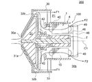
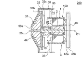
- FIG. 1 is a longitudinal sectional view showing an electric blower 200 according to Embodiment 1 of the present invention.
- the electric blower 200 includes a motor 100 having a rotating shaft 25, a moving blade (fan) 31 attached to one end of the rotating shaft 25 of the motor 100, a stationary blade 32 disposed adjacent to the moving blade 31, And a housing 30 for housing them.
- the direction of the axis C1 that is the central axis of the rotary shaft 25 is referred to as “axial direction”.
- the circumferential direction around the axis C1 is referred to as “circumferential direction”.
- the radial direction centered on the axis C1 is referred to as “radial direction”.
- a cross-sectional view in a cross section parallel to the axial direction is referred to as a “longitudinal cross-sectional view”
- a cross-sectional view in a cross section orthogonal to the axial direction is referred to as a “transverse cross-sectional view”.
- the motor 100 is a permanent magnet synchronous motor and is a single phase motor driven by an inverter.
- the motor 100 includes a motor frame (also simply referred to as a frame) 4, a stator 1 fixed in the motor frame 4, a rotor 2 provided inside the stator 1, and a rotating shaft 25 fixed at the center of the rotor 2. And have. A specific configuration of the motor 100 will be described later.
- FIG. 2 is a schematic diagram showing the motor frame 4 and the motor 100.
- the motor frame 4 includes a motor housing portion (that is, a peripheral wall portion) 40 and a bearing housing portion 44 formed on the moving blade 31 side of the motor housing portion 40. Both the motor housing portion 40 and the bearing housing portion 44 have a cylindrical shape centered on the axis C1. Inside the motor housing 40 is a stator insertion space 201 into which the stator 1 is inserted.
- the outer diameter of the bearing housing portion 44 is smaller than the outer diameter of the motor housing portion 40. Inside the bearing housing portion 44 is a bearing insertion space 202 into which the bearing 45 is inserted.
- the bearing housing portion 44 has a wall portion 44a on the moving blade 31 side, and a hole 44b through which the rotary shaft 25 passes is formed in the wall portion 44a.
- Two bearings 45 as bearing portions are attached inside the bearing housing portion 44.
- the outer ring of the bearing 45 is fitted inside the bearing housing portion 44, and the rotary shaft 25 is press-fitted into the inner ring of the bearing 45.
- the two bearings 45 are arranged at an interval in the axial direction.
- a sleeve or the like may be disposed between the two bearings 45.
- a wall 41 is formed between the motor housing 40 and the bearing housing 44.
- the wall 41 extends in a direction orthogonal to the axis C1.
- the wall 41 is formed with a hole 42 through which air passes in the axial direction.
- FIG. 3 is a cross-sectional view taken along line III-III shown in FIG.
- the hole 42 is for guiding the air flow generated in the rotor blade 31 to the inside of the motor frame 4 as described later.
- four holes 42 are formed in the circumferential direction, and each hole 42 has an arc shape centered on the axis C ⁇ b> 1.
- the hole 42 is not limited to such a shape and number.
- FIG. 4 is a perspective view showing an example in which the moving blade 31 is composed of a mixed flow fan. 4 includes a plurality of blades 31a on the surface of a conical hub 31b centered on the axis C1. The moving blade 31 is inclined with respect to the axial direction and generates a flow of air that is directed radially outward.
- the moving blade 31 is not limited to a mixed flow fan, and may be a turbo fan, for example.
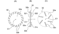
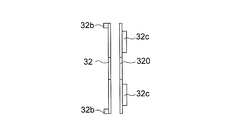
- the stationary blade 32 includes a disk-shaped main plate 32 a, a plurality of blades 32 b formed on the first surface 321 of the main plate 32 a on the moving blade 31 side, and a first blade 32 b opposite to the moving blade 31. And a plurality of air guide plates 32 c formed on the second surface 322.
- the stationary blade 32 has a hole 32d at the radial center, and the bearing housing portion 44 is fitted in the hole 32d.
- the stationary blade 32 is fixed by, for example, bonding or fastening with screws.
- FIG. 5 (A) is a diagram showing the shape and arrangement of the blades 32b of the stationary blade 32.
- FIG. FIG. 5B is a side view of the stationary blade 32.
- FIG. 5C is a diagram showing the shape and arrangement of the air guide plate 32 c of the stationary blade 32.
- 5A and 5C both show the shape and arrangement viewed from the moving blade 31 side.
- the blades 32b are arranged at equal intervals in the circumferential direction, and each extends in a direction inclined with respect to the radial direction. Further, the blade 32b is formed in the outer peripheral region of the first surface 321 and is located on the radially outer side with respect to the moving blade 31 (FIG. 4). The blade 32 b has a function of rectifying the air flow generated by the rotation of the moving blade 31.
- the air guide plates 32c are arranged at equal intervals in the circumferential direction, and each extend in a direction inclined with respect to the radial direction. Note that the direction of inclination of the air guide plate 32c is opposite to the direction of inclination of the blade 32b. Further, the air guide plate 32c extends radially inward from the blade 32b. The air guide plate 32c has a function of directing the air flow rectified by the blades 32b to the inner side in the radial direction and guiding it to the motor frame 4 side.
- the electric blower 200 has a cantilever structure in which the rotating shaft 25 is supported by two bearings 45 disposed between the moving blade 31 and the stator 1 in the axial direction. That is, the electric blower 200 has a configuration in which the center of the rotating shaft 25, the center of the stator 1 and the center of the bearing 45 can be matched with high accuracy.
- the number of bearings 45 is not limited to two, and may be three or more.
- the housing 30 has a fan cover 34 formed along the moving blade 31 and a suction port 30 a facing the radial center of the moving blade 31. Further, the housing 30 has a frame support portion 33 that supports the motor frame 4. Here, a plurality of frame support portions 33 are provided radially about the axis C1. The housing 30 is open on the side opposite to the fan cover 34 and serves as an exhaust port 30b.
- the electric blower 200 includes a first air passage P1 outside the motor frame 4 and a second air passage inside the motor frame 4 as a passage (that is, an air passage) for air flowing into the housing 30 from the suction port 30a. And an air path P2.
- the air that has flowed through the first air path P1 is directly discharged from the exhaust port 30b.
- the air flowing through the second air passage P2 passes through the motor 100 in the axial direction.
- a substrate 48 for controlling the driving of the motor 100 is provided on the side opposite to the rotor blade 31 with respect to the motor 100.
- the substrate 48 is fixed to the motor frame 4 or the stator 1 by a fixing member 49.
- the substrate 48 includes a sensor guide 46 that guides a lead wire of a sensor 7 (described later) of the motor 100.
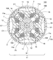
- FIG. 6 is a cross-sectional view showing motor 100 of the first embodiment.
- the motor 100 includes the rotor 2 and the stator 1 provided so as to surround the rotor 2.
- the rotor 2 rotates clockwise in the figure around the axis C1.
- the direction of rotation of the rotor 2 is indicated by an arrow R1.
- the rotor 2 has a rotating shaft 25 and permanent magnets 21 and 22 fixed around the rotating shaft 25.
- the permanent magnets 21 and 22 are arranged at equal intervals in the circumferential direction, and each constitutes a magnetic pole.
- the outer peripheral surface of the permanent magnet 21 is, for example, an N pole, and the outer peripheral surface of the permanent magnet 22 is, for example, an S pole, but may be reversed.
- the two permanent magnets 21 and the two permanent magnets 22 are alternately arranged in the circumferential direction. That is, the rotor 2 has four magnetic poles. However, the number of magnetic poles of the rotor 2 is not limited to four and may be two or more.
- the stator 1 is provided on the outer side in the radial direction of the rotor 2 through an air gap.
- the stator 1 includes a stator core 10, an insulating portion 14, and a coil 18.
- the stator core 10 is formed by laminating a plurality of laminated elements in the axial direction and integrally fixing with caulking portions 101, 102, 103.
- the laminated element is a magnetic steel sheet, and the thickness is, for example, 0.25 mm.
- the stator core 10 includes a yoke 11 surrounding the rotor 2 and a plurality of teeth 12 extending in a direction from the yoke 11 toward the rotor 2 (that is, radially inward).
- the teeth 12 are arranged at equal intervals in the circumferential direction.
- the number of teeth 12 is the same as the number of magnetic poles of the rotor 2, and is four here.
- a slot 13 is formed between two teeth 12 adjacent to each other in the circumferential direction in the stator core 10.
- an insulating part 14 made of an insulating resin is provided in the slot 13.
- a coil 18 is wound around the tooth 12 via an insulating portion 14.
- the yoke 11 of the stator core 10 includes a plurality of arc-shaped back yokes 11a and a linear connection yoke 11b positioned radially inward of the back yoke 11a.
- the back yoke 11a is a portion of the stator 1 that is located on the outermost radial direction, and is arranged at equal intervals in the circumferential direction.
- the number of back yokes 11a is the same as the number of teeth 12, and is four here.
- the teeth 12 are positioned between two back yokes 11a adjacent in the circumferential direction.
- the outer peripheral surface of the back yoke 11a is fitted to the inner peripheral surface of the motor housing portion 40 of the motor frame 4 (FIG. 1).
- the connecting yoke 11b extends so as to connect the back yoke 11a and the teeth 12.
- the connecting yoke 11b extends linearly so as to be displaced inward in the radial direction as the distance from the back yoke 11a increases.
- the teeth 12 extend toward the rotor 2 from a portion where two connecting yokes 11b adjacent to each other in the circumferential direction are connected in a V shape (that is, a portion located on the innermost radial direction of the yoke 11). Yes.
- a split surface (that is, a split fitting portion) 106 is formed at the center in the circumferential direction of the back yoke 11a.
- the stator core 10 is divided into a plurality of blocks, that is, divided cores 17 for each tooth 12 on a divided surface 106 formed on the back yoke 11a.
- the stator core 10 is divided into four divided cores 17.
- the dividing surface 106 has a convex part or a concave part. Of the two split cores 17 adjacent to each other in the circumferential direction, the convex portion of the split surface 106 of one split core 17 and the concave portion of the split surface 106 of the other split core 17 are fitted.
- the stator core 10 is integrally fixed by caulking portions 101, 102, and 103.
- the crimping portions 101 and 102 are formed on the yoke 11, and the crimping portion 103 is formed on the tooth 12.
- the crimping portions 101 and 102 are desirably formed at a position as close as possible to the dividing surface 106 in the yoke 11, that is, in the back yoke 11a.
- a fixing recess 105 which is a long groove in the axial direction is formed.
- a part of the motor housing portion 40 is pressed from the outer peripheral side to be deformed and fitted into the fixing recess 105. Thereby, rotation of the stator 1 in the motor frame 4 is prevented.
- a configuration without the fixing recess 105 is also possible.
- the tip end portion of the tooth 12 has an asymmetric shape with respect to a radial straight line passing through the center in the width direction of the tooth 12.
- the shape is not limited to such a shape. Alternatively, it may have a symmetric shape.
- Sensor fixing portions 15 a and 15 b are provided on both sides in the circumferential direction of the tip of the tooth 12.
- the sensor fixing portions 15 a and 15 b protrude from the tip end portion of the tooth 12 in the circumferential direction.
- the sensor fixing portions 15 a and 15 b are formed integrally with the insulating portion 14.
- a sensor 7 for detecting the magnetic field of the rotor 2 is held between the sensor fixing portions 15a and 15b of the four sets of the sensor fixing portions 15a and 15b of the stator 1.
- the sensor 7 has a Hall effect element integrated with a resin package, and a lead wire is drawn from one end face in the axial direction.
- the sensor 7 is disposed to face the outer peripheral surface of the rotor 2 in order to detect the magnetic field of the rotor 2.
- the insulating portion 14 and the sensor fixing portions 15a and 15b are assembled to the respective split cores 17 (FIG. 6). Then, after winding the coil 18 around the insulating portion 14, the four divided cores 17 are combined with each other to obtain the stator 1. Further, the sensor 7 is inserted into the sensor fixing portions 15 a and 15 b between the two teeth 12.
- FIG. 7 is a view showing a state in which the motor 100 configured as described above is attached to the motor frame 4 (FIG. 1).
- the outer peripheral surface of the back yoke 11 a of the stator 1 is fitted to the inner peripheral surface of the motor housing portion 40. Since the stator 1 has the fixing recess 105 described above, an external force is applied to a portion corresponding to the fixing recess 105 of the motor accommodating portion 40 (denoted by reference numeral 40 a) and engaged with the fixing recess 105. Thereby, the position shift of the circumferential direction of the motor 100 can be prevented.
- FIG. 8 is a diagram illustrating an air flow in the electric blower 200.
- the motor 100 is rotated by energization of the coil 18, the rotary shaft 25 rotates and the rotor blade 31 rotates.
- the moving blade 31 rotates, air flows into the housing 30 from the suction port 30a.
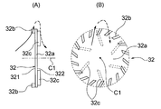
- FIG. 9 is a side view (A) showing the operation of the stationary blade 32 and a front view (B) viewed from the moving blade 31 side.
- the blade 32b of the stationary blade 32 rectifies the air (indicated by the solid line arrow) flowing along the moving blade 31 and guides it radially outward.
- the air guide plate 32c of the stationary blade 32 guides the air that has passed through the blade 32b to the inside in the radial direction as indicated by the broken line arrow.
- a part of the air that has passed through the stationary blade 32 flows in the first wind path P1 outside the motor frame 4 in the axial direction. Further, another part of the air that has passed through the stationary blade 32 is guided radially inward by the air guide plate 32c of the stationary blade 32, as indicated by an arrow F2, passes through the hole 42, and enters the inside of the motor frame 4. And flows through the second air passage P2 in the axial direction.
- the air flowing into the motor frame 4 passes through the gap 19 between the stator 1 and the motor housing 40 shown in FIG. 7, the inside of each slot 13 of the stator 1, and the air gap between the stator 1 and the rotor 2. , Flowing axially. Therefore, the heat generated in the coil 18 when the motor 100 is driven can be efficiently radiated by the air flowing through the second air path P2.
- FIG. 10 is a schematic diagram for explaining the air volume in the first air path P1 and the second air path P2.
- the air volume of the first air path P1 and the air volume of the second air path P2 are represented by the thickness of the arrows shown in FIG.
- the stator 1 and the rotor 2 serving as the air path resistance are disposed in the second air path P2.
- the first air passage P1 having a low air passage resistance is used as the main air passage. That is, the air volume is improved by increasing the air volume of the first air path P1, and the air flow of the air volume smaller than that of the first air path P1 is caused to flow through the second air path P2. It has improved.
- the air efficiency refers to the ratio of the aerodynamic output to the electric power input to the motor 100, and the aerodynamic output is obtained by the product of the air volume and the static pressure.
- the main air path is a case where the first air path P1 is completely blocked and only the second air path P2 is used, and a case where the second air path P2 is completely blocked and the first air path P1 is used. This is the case where only air is used, and the air path with the larger air volume at the same rotational speed.
- the first air passage P1 is the main air passage.
- FIG. 11 is a schematic diagram showing an air path along the substrate 48.
- the air that has flowed through the first air path P1 and the second air path P2 strikes the surface of the substrate 48 and changes its direction, and goes outward in the radial direction.
- the substrate 48 has elements and patterns for controlling the motor 100, and generates heat when driven, so that heat can be radiated by the air flowing on the surface of the substrate 48.
- the distance that the air that has flowed through the first air path P1 flows radially outward along the surface of the substrate 48 is defined as B1.
- the distance that the air that has flowed through the second air path P2 flows radially outward along the surface of the substrate 48 is defined as B2. Since the second air path P2 is located on the radially inner side of the first air path P1, B1 ⁇ B2 is established.
- the air efficiency of the electric blower 200 is determined by the air volume of the first air path P1, which is the main air path, the air volume of the second air path P2 has little influence on the air efficiency. Therefore, the substrate 48 can be radiated while improving the air efficiency by radiating the substrate 48 with the air flowing through the second air path P2. Further, since the air volume hitting the substrate 48 is not increased too much, the substrate 48 can be prevented from coming off.
- FIG. 12 is a schematic diagram showing the relationship between the first air path P 1 and the second air path P 2 and the substrate 48.
- the substrate 48 has a first circuit region 48 a on the side facing the motor 100 and a second circuit region 48 b on the side opposite to the motor 100.
- the first circuit region 48a has elements and patterns for supplying power to the motor 100, that is, elements and patterns through which a relatively large current (for example, 1 A or more) flows.
- the second circuit region 48b has elements and patterns for controlling the motor 100, that is, elements and patterns through which a relatively small current (for example, 1 mA level) flows.
- the efficiency can be improved by direct application to the air flowing through the first air path P1 and the second air path P2. It can dissipate heat well.
- stator core 10 is composed of the combination of the split cores 17 (FIG. 6), the assembling work of the insulating portion 14 and the winding work of the coil 18 are easier than the integrated core. is there.
- the motor 100 when the motor 100 is downsized, the coil 18 becomes difficult to wind and the space factor tends to decrease.
- the motor 100 can be downsized by configuring the stator core 10 with a combination of the split cores 17 (FIG. 6). Even in this case, the coil 18 can be wound with high density to improve the space factor.
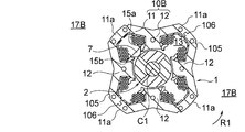
- FIG. 13 is a schematic diagram for explaining an exposed portion of the stator 1 in the motor frame 4.
- a portion of the stator 1 surrounded by a broken line E1 is covered with an insulating portion 14, and a coil 18 is wound thereon.
- a portion including the dividing surface 106 that is, a part of the back yoke 11a
- the coil 18 is not wound. Therefore, this portion is exposed in the second air path P2, and the air directly hits it.
- the split surface 106 is formed by punching a magnetic steel sheet with a mold, but strain (that is, punch strain) generated during the punching process remains on the split surface 106.
- strain that is, punch strain
- the punching distortion lowers the magnetic permeability of the stator core 10, so that when the magnetic flux passes through the dividing surface 106, a loss is locally generated, and thus heat is generated locally.
- FIG. 13 shows the stator core 10 configured by combining the split cores 17, as shown in FIG. 19 to be described later, the stator core 10B connected by the thin-walled portion (connecting portion) 112 (that is, the connecting core) Also for the stator core 10B) configured in combination, the heat generated locally due to the punching distortion can be efficiently radiated by exposing the thin portion 112 to the second air path P2.
- the minimum cross-sectional areas of the first air path P1 and the second air path P2 will be described.
- the air passage cross-sectional area is minimized at the portion where the frame support portion 33 is provided in the housing 30.
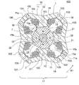
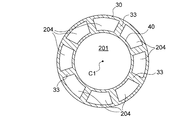
- FIG. 14 is a cross-sectional view of the housing 30 at a portion where the frame support portion 33 is provided.
- Eight frame support portions 33 are provided between the housing 30 and the motor housing portion 40 of the motor frame 4.
- the eight frame support portions 33 are formed radially about the axis C1.
- An opening 204 through which air passes in the axial direction is formed between the frame support portions 33 adjacent in the circumferential direction.
- the total area of the openings 204 is S1.
- the air passage cross-sectional area is minimized by the hole 42 of the motor frame 4.
- the wall 41 of the motor frame 4 has four holes 42 through which air passes in the axial direction.
- the total area of the holes 42 is S2.
- the minimum cross-sectional area S1 of the first air passage P1 is larger than the minimum cross-sectional area S2 of the second air passage P2. This is because the first air passage P1 is used as the main air passage.
- FIG. 15 shows the ratio of the minimum cross-sectional area S2 of the second air passage P2 to the minimum cross-sectional area S1 of the first air passage P1 (referred to as area ratio S2 / S1), the air efficiency, and the heat generation amount of the motor 100. It is a graph which shows a relationship.
- FIG. 15 shows that when the area ratio S2 / S1 increases, the air efficiency does not change, but the amount of heat generated by the motor 100 decreases. Further, it can be seen that when the area ratio S2 / S1 is in the range of 2% or more, the decreasing tendency of the heat generation amount of the motor 100 becomes moderate. From this result, it is understood that the area ratio S2 / S1 is desirably 2% or more in order to improve the heat dissipation of the motor 100.
- the rotary shaft 25 is rotatably supported by two bearings 45 provided between the moving blade 31 and the stator 1 in the axial direction. Therefore, the center positions of the two bearings 45 are not shifted from each other.
- stator 1 and the bearing 45 are supported by the common motor frame 4, there is no assembly tolerance as in the case where the stator 1 and the bearing 45 are supported by different members.
- the center of the rotating shaft 25, the center of the stator 1, and the center of the bearing 45 can be made to coincide with each other accurately, thereby preventing the whirling due to the centrifugal force.
- the influence on rotation by the electromagnetic force which acts between the stator 1 and the rotor 2 can be suppressed.
- the rotating shaft 25 is supported by the bearing 45 disposed between the moving blade 31 and the stator 1 in the axial direction. Further, the stator 1 is accommodated in the motor accommodating portion 40 of the motor frame 4, and the bearing 45 is accommodated in the bearing accommodating portion 43. A hole 42 is formed in the motor frame 4, and a first air path P ⁇ b> 1 outside the motor frame 4 and a second air path P ⁇ b> 2 inside the motor frame 4 are provided. The amount of air flowing through the first air passage P1 is larger than the amount of air flowing through the second air passage P2.
- the air guide plate 32c on the stationary blade 32, the air that has passed through the moving blade 31 can be efficiently guided to the second air path, and the heat dissipation of the motor 100 can be improved.
- the air flow generated in the moving blade 31 is guided to the second air path P2 by the air guide plate 32c provided in the stationary blade 32 (FIG. 1).
- the air guide plate 32c is not necessarily provided on the stationary blade 32, and may be provided on a plate-like member 320 different from the stationary blade 32 as shown in FIG.
- the plate-like member 320 in FIG. 16 has a wind guide plate 32 c on the surface opposite to the side facing the stationary blade 32.
- the structure of the air guide plate 32c is as described with reference to FIG.
- FIG. 17 is a longitudinal sectional view showing an electric blower 200A of the second embodiment.
- the first air passage P1 is provided with an air passage resistor 36 that provides air passage resistance (that is, increases pressure loss).
- the air path resistor 36 acts as an air guide member that guides the air that has flowed into the housing 30 by the moving blade 31 to the second air path P2.
- the air path resistor 36 is fixed to the outer peripheral surface of the motor frame 4, and a gap is provided between the air path resistor 36 and the inner peripheral surface of the housing 30.
- the air path resistor 36 only needs to be a resistance to the air flowing through the first air path P1.
- a porous body is desirable so as not to completely block the air flow. If the air path resistor 36 is made of a porous elastic body such as a sponge, the air path resistor 36 can be fixed so as to be wound around the outer peripheral surface of the motor frame 4, so that assembly is easy. Therefore, it is desirable to use a soundproof material as the air path resistor 36, for example.
- the electric blower 200A of the second embodiment is configured in the same manner as the electric blower 200 of the first embodiment except that the air path resistor 36 is provided in the first air path P1.
- the air flow resistor 36 of the first air path P1 is configured to guide the air flowing into the housing 30 to the second air path P2, as in the first embodiment, The heat generated in the coil 18 when the motor 100 is driven can be efficiently radiated by the air flowing through the second air path P2.
- the air guide plate 32c of the stationary blade 32 may be omitted. This is because the air from the rotor blade 31 can be guided to the second air path P2 only by the air path resistor 36.
- FIG. 18A is a cross-sectional view showing the motor of the third embodiment.
- the motor 100 (FIG. 6) of the first embodiment described above has the stator core 10 in which a plurality of divided cores 17 are combined.
- the motor according to the third embodiment has a stator core 10A in which a plurality of connecting cores 17A connected by the thin portion 112 are combined.
- the three back yokes 11a have separation surfaces 111 instead of the division surfaces 106 described in the first embodiment (FIG. 6). And the thin part 112 is formed.
- the separation surface 111 extends from the inner periphery to the outer periphery of the back yoke 11a, but does not reach the outer periphery of the back yoke 11a.
- a deformable thin portion (that is, a connecting portion) 112 is formed between the terminal end of the separation surface 111 and the outer periphery of the back yoke 11a.
- a caulking may be provided instead of the thin portion 112.
- a welding surface (that is, a bonding surface) 113 is formed on one of the four back yokes 11a of the stator core 10A.
- the welding surface 113 extends from the inner periphery to the outer periphery of the back yoke 11a and reaches the outer periphery of the back yoke 11a.
- each block separated by the separation surface 111 and the thin portion 112 (or the welding surface 113) is referred to as a connecting core 17A.
- the stator core 10 ⁇ / b> A has four connection cores 17 ⁇ / b> A for each tooth 12.
- FIG. 18B is a schematic diagram showing a state where the stator core 10A is developed in a band shape.
- the stator core 10A can be developed in a band shape as shown in FIG. 18B from the state shown in FIG. 18A by deforming the thin portion 112.
- Each of the connecting cores 17A is connected by the thin portion 112 and connected in a row.
- the welding surfaces 113 are located at both ends of the row.
- the insulating portion 14 (including the sensor fixing portions 15a and 15b) is assembled to the connecting core 17A in a state where the connecting core 17A is expanded in a band shape (FIG. 18B). Then, after winding the coil 18 around the insulating portion 14, the connecting core 17A is bent in an annular shape, and the welding surface 113 is welded to obtain the stator core 10A. Thereafter, the sensor 7 is attached to the sensor fixing portions 15 a and 15 b between the two teeth 12.
- Other configurations of the stator core 10A are the same as those of the stator core 10 described in the first embodiment.
- the stator core 10A is composed of the connecting core 17A, the assembling work of the insulating portion 14 and the sensor fixing portions 15a and 15b and the winding work of the coil 18 are compared with the integrated core. Is easy. Therefore, even when the motor 100 is downsized, the coil 18 can be wound at a high density and the space factor can be improved.
- FIG. 19 is a cross-sectional view showing a motor according to a first modification of the third embodiment.
- the motor of the third embodiment described above (FIG. 18A) has a stator core 10A in which a plurality of connecting cores 17A are combined for each tooth 12.
- the motor of the first modification has a stator core 10B in which a plurality of divided cores 17B each including two teeth 12 are combined.
- the two back yokes 11a are provided with the dividing surfaces 106 described in the first embodiment (FIG. 6), and the remaining two back yokes 11a.
- the yoke 11a is not provided with the dividing surface 106.
- the back yoke 11a provided with the dividing surface 106 and the back yoke 11a not provided with the dividing surface 106 are alternately arranged in the circumferential direction.
- stator core 10B each block divided by the dividing surface 106 is referred to as a divided core 17B.
- stator core 10 ⁇ / b> B has two divided cores 17 ⁇ / b> B each including two teeth 12.
- the insulating portion 14 (including the sensor fixing portions 15a and 15b) is assembled to each divided core 17B. Then, after winding the coil 18 around the insulating portion 14, the two split cores 17B are combined with each other to obtain the stator core 10B. Thereafter, the sensor 7 is attached to the sensor fixing portions 15 a and 15 b between the two teeth 12.
- Other configurations of the stator core 10B are the same as those of the stator core 10 described in the first embodiment. Also in this first modification, the same effect as in the third embodiment can be obtained.
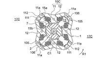
- FIG. 20 is a cross-sectional view showing a motor according to a second modification of the third embodiment.
- the motor of the third embodiment described above (FIG. 18A) has a stator core 10A in which a plurality of connecting cores 17A are combined.
- the motor of the second modification has a stator core 10C in which a split core and a connecting core are combined.
- the two back yokes 11a are provided with the split surfaces 106 described in FIG. 11a is provided with the separation surface 111 and the thin portion 112 described in Embodiment 3 (FIG. 18), and the back yoke 11a provided with the division surface 106, and the separation surface 111 and the thin portion 112.
- the provided back yokes 11a are alternately arranged in the circumferential direction.
- each block divided by the dividing surface 106 is referred to as a divided core 17C.
- the stator core 10 ⁇ / b> B has two divided cores 17 ⁇ / b> C each including two teeth 12.
- Each split core 17 ⁇ / b> C can be developed at the center in the circumferential direction by the thin portion 112.
- the insulating portions 14 (including the sensor fixing portions 15a and 15b) are assembled in a state where the respective divided cores 17C are spread in a band shape. Then, after winding the coil 18 around the insulating portion 14, the two split cores 17C are combined with each other to obtain the stator core 10B. Thereafter, the sensor 7 is attached to the sensor fixing portions 15 a and 15 b between the two teeth 12.
- Other configurations of the stator core 10C are the same as those of the stator core 10 described in the first embodiment. Also in this second modification, the same effect as in the third embodiment can be obtained.
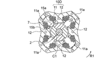
- FIG. 21 is a cross-sectional view showing a motor according to a third modification of the third embodiment.
- the motor of the third embodiment described above (FIG. 18A) has a stator core 10A in which a plurality of connecting cores 17A are combined.
- the motor of the fourth modified example has an integrally configured stator core 10D.
- the split surface 106 described in the first embodiment is not provided in the stator core 10D, and the separation surface 111 and the thin portion described in the third embodiment (FIG. 18). 112 is also not provided. Therefore, it is necessary to assemble the insulating portion 14 and the sensor fixing portions 15a and 15b to the annular stator core 10D, and further wind the coil 18.
- Other configurations of the stator core 10D are the same as those of the stator core 10 described in the first embodiment.
- stator cores 10 to 10D having four teeth 12 have been described, but the number of teeth may be two or more.
- the yoke 11 of the stator cores 10 to 10D includes the back yoke 11a and the connecting yoke 11b, it may be an annular yoke.
- FIG. 22 is a schematic diagram illustrating a vacuum cleaner 300 using the electric blower 200 (FIG. 1) of the first embodiment.
- the electric vacuum cleaner 300 includes a vacuum cleaner main body 301, a pipe 303 connected to the vacuum cleaner main body 301, and a suction part 304 connected to the tip of the pipe 303.
- the suction unit 304 is provided with a suction port 305 for sucking air containing dust.
- a dust collection container 302 is disposed inside the cleaner body 301.
- An electric blower 200 that sucks air containing dust from the suction port 305 to the dust collecting container 302 is disposed inside the cleaner body 301.
- the electric blower 200 has the configuration shown in FIG. 1, for example.
- the cleaner body 301 is also provided with a grip portion 306 that is gripped by the user, and the grip portion 306 is provided with an operation portion 307 such as an on / off switch.
- the electric blower 200 When the user grips the grip portion 306 and operates the operation portion 307, the electric blower 200 operates and the motor 100 rotates. When the electric blower 200 is operated, suction air is generated, and dust is sucked together with air through the suction port 305 and the pipe 303. The sucked dust is stored in the dust collecting container 302.
- the electric vacuum cleaner 300 uses the highly reliable electric blower 200, high operating efficiency can be obtained.
- the electric blowers of other embodiments or modifications may be used.
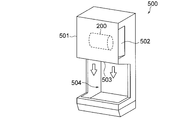
- FIG. 23 is a schematic diagram showing a hand dryer 500 using the electric blower 200 (FIG. 1) of the first embodiment.
- the hand dryer 500 has a housing 501 and an electric blower 200 fixed inside the housing 501.
- the electric blower 200 has the configuration shown in FIG. 1, for example.
- the housing 501 has an air inlet 502 and an air outlet 503, and a hand insertion unit 504 into which a user inserts a hand below the air outlet 503.
- the electric blower 200 sucks air outside the housing 501 through the air inlet 502 by generating an air flow, and blows air to the manual insertion portion 504 through the air outlet 503.
- the power of the hand dryer 500 When the power of the hand dryer 500 is turned on, electric power is supplied to the electric blower 200 and the motor 100 is driven. While the electric blower 200 is driven, air outside the hand dryer 500 is sucked from the air inlet 502 and blown from the air outlet 503. When the user inserts a hand into the hand insertion portion 504, the water droplets attached to the hand can be blown out or evaporated by the air blown from the air blowing port 503.
- the hand dryer 500 uses the highly reliable electric blower 200, high operating efficiency can be obtained.
- the electric blowers of other embodiments or modifications may be used.
Landscapes
- Engineering & Computer Science (AREA)
- Mechanical Engineering (AREA)
- General Engineering & Computer Science (AREA)
- Physics & Mathematics (AREA)
- Thermal Sciences (AREA)
- Power Engineering (AREA)
- Structures Of Non-Positive Displacement Pumps (AREA)
- Iron Core Of Rotating Electric Machines (AREA)
Abstract
電動送風機は、回転シャフトを有するロータと、ロータを囲むように設けられたステータとを有するモータと、回転シャフトの軸方向の一端側に取り付けられた動翼と、軸方向において動翼とステータとの間に設けられ、回転シャフトを回転可能に支持する軸受部と、フレームとを備える。フレームは、ステータを収容するモータ収容部と、軸受部を収容する軸受収容部と、モータ収容部と軸受収容部との間に形成され、動翼に対向する壁部と、壁部を貫通する穴とを有する。電動送風機は、また、フレームの外側の第1の風路と、フレームの内側の第2の風路とを有する。第1の風路を流れる風量は、第2の風路を流れる風量よりも大きい。
Description
本発明は、電動送風機、電気掃除機および手乾燥装置に関する。
電動送風機の小型化に伴い、電動送風機のモータの回転数の高速化が求められている。モータの回転数が高速化すると、モータの回転部分に作用する遠心力が大きくなる。そのため、モータの回転シャフトの中心と、ステータの中心と、回転シャフトを支持する軸受の中心とが正確に一致していないと、遠心力による振れ回りが生じる可能性がある。
例えば、特許文献1には、モータフレームの軸方向の一端に1つの軸受を取り付け、軸方向の他端にブラケットを介してもう1つの軸受を取り付けたモータが提案されている。
しかしながら、上記のように2つの軸受を別々の部材に取り付けたのでは、軸受同士の中心を一致させることが難しく、高速回転に適した構成とは言えない。
また、モータの回転数の高速化に伴い、モータの発熱量が増加するため、放熱効率の向上も望まれる。
本発明は、上記課題を解決するためになされたものであり、回転部分の振れ回りを抑制し、且つ放熱効率の高い電動送風機を提供することを目的とする。
本発明の電動送風機は、回転シャフトを有するロータと、ロータを囲むように設けられたステータとを有するモータと、回転シャフトの軸方向の一端側に取り付けられた動翼と、軸方向において動翼とステータとの間に設けられ、回転シャフトを回転可能に支持する軸受部と、フレームとを備える。フレームは、ステータを収容するモータ収容部と、軸受部を収容する軸受収容部と、モータ収容部と軸受収容部との間に形成され、動翼に対向する壁部と、壁部を貫通する穴とを有する。電動送風機は、また、フレームの外側の第1の風路と、フレームの内側の第2の風路とを有する。第1の風路を流れる風量は、第2の風路を流れる風量よりも大きい。
本発明によれば、動翼とステータとの間に配置した軸受部によって回転シャフトを回転可能に支持するため、回転シャフトの中心と、ステータの中心と、軸受の中心とを一致させやすい。そのため、遠心力による振れ回りを抑制することができる。また、フレームの内側の第2の風路を流れる空気によって、モータで発生した熱が効率よく放熱される。
以下、本発明の実施の形態について、図面を参照して詳細に説明する。なお、この実施の形態により本発明が限定されるものではない。
実施の形態1.
<電動送風機200の構成>
図1は、本発明の実施の形態1の電動送風機200を示す縦断面図である。電動送風機200は、回転シャフト25を有するモータ100と、モータ100の回転シャフト25の一端側に取り付けられた動翼(ファン)31と、動翼31に隣接して配置された静翼32と、これらを収容する筐体30とを備える。
<電動送風機200の構成>
図1は、本発明の実施の形態1の電動送風機200を示す縦断面図である。電動送風機200は、回転シャフト25を有するモータ100と、モータ100の回転シャフト25の一端側に取り付けられた動翼(ファン)31と、動翼31に隣接して配置された静翼32と、これらを収容する筐体30とを備える。
以下では、回転シャフト25の中心軸線である軸線C1の方向を、「軸方向」と称する。また、軸線C1を中心とする周方向を、「周方向」と称する。また、軸線C1を中心とする半径方向を、「径方向」と称する。また、軸方向に平行な断面における断面図を「縦断面図」と称し、軸方向に直交する断面における断面図を「横断面図」と称する。
モータ100は、永久磁石同期モータであり、インバータによって駆動される単相モータである。モータ100は、モータフレーム(単にフレームとも称する)4と、モータフレーム4内に固定されたステータ1と、ステータ1の内側に設けられたロータ2と、ロータ2の中心に固定された回転シャフト25とを有する。モータ100の具体的な構成については、後述する。
図2は、モータフレーム4とモータ100とを示す模式図である。モータフレーム4は、モータ収容部(すなわち周壁部)40と、モータ収容部40の動翼31側に形成された軸受収容部44とを有する。モータ収容部40および軸受収容部44は、いずれも、軸線C1を中心とする円筒形状を有する。モータ収容部40の内側は、ステータ1が挿入されるステータ挿入スペース201である。
軸受収容部44の外径は、モータ収容部40の外径よりも小さい。軸受収容部44の内側は、軸受45が挿入される軸受挿入スペース202である。また、軸受収容部44は、動翼31側に壁部44aを有し、この壁部44aには、回転シャフト25を貫通させる穴44bが形成されている。
軸受収容部44の内側には、軸受部としての2つの軸受45が取り付けられている。軸受45の外輪は、軸受収容部44の内側に嵌合し、軸受45の内輪には回転シャフト25が圧入されている。2つの軸受45は、軸方向に間隔を開けて配置されている。なお、2つの軸受45の間に、スリーブ等を配置しても良い。
モータ収容部40と軸受収容部44との間には、壁部41が形成されている。壁部41は、ここでは、軸線C1に直交する方向に延在している。壁部41には、空気を軸方向に通過させる穴42が形成されている。
図3は、図2に示す線分III-IIIにおける断面図である。穴42は、後述するように動翼31で生じた空気の流れをモータフレーム4の内側に導くためのものである。図3に示した例では、周方向に4つの穴42が形成されており、それぞれの穴42は、軸線C1を中心とする円弧形状を有している。但し、穴42は、このような形状および数に限定されるものではない。
図4は、動翼31を斜流ファンで構成した例を示す斜視図である。図4に示す動翼31は、軸線C1を中心とする円錐形状のハブ31bの表面に、複数の羽根31aを備える。動翼31は、軸方向に対して傾斜し、且つ径方向外側に向かう空気の流れを生成する。動翼31は、斜流ファンに限定されるものではなく、例えばターボファンであってもよい。
図1に戻り、静翼32は、円板状の主板32aと、主板32aの動翼31側の第1の面321に形成された複数の羽根32bと、動翼31とは反対側の第2の面322に形成された複数の導風板32cとを有する。静翼32は、径方向の中央部に穴32dを有し、この穴32dに軸受収容部44が嵌合している。静翼32の固定は、例えば接着またはねじによる締結による。
図5(A)は、静翼32の羽根32bの形状および配列を示す図である。図5(B)は、静翼32の側面図である。図5(C)は、静翼32の導風板32cの形状および配列を示す図である。なお、図5(A)および図5(C)は、いずれも、動翼31側から見た形状および配列を示している。
図5(A),(B)に示すように、羽根32bは、周方向に等間隔に配列され、それぞれが径方向に対して傾斜する方向に延在している。また、羽根32bは、第1の面321の外周領域に形成されており、動翼31(図4)に対して径方向外側に位置している。羽根32bは、動翼31の回転によって生じた空気の流れを整流する作用を有する。
図5(B),(C)に示すように、導風板32cは、周方向に等間隔に配列され、それぞれが径方向に対して傾斜する方向に延在している。なお、導風板32cの傾斜方向は、羽根32bの傾斜方向とは反対向きである。また、導風板32cは、羽根32bよりも径方向内側まで延在している。導風板32cは、羽根32bによって整流された空気の流れを径方向内側に向け、モータフレーム4側に導く作用を有する。
図1に戻り、電動送風機200は、軸方向において動翼31とステータ1との間に配置された2つの軸受45によって回転シャフト25を支持する片持ち構造を有する。すなわち、電動送風機200は、回転シャフト25の中心と、ステータ1の中心と、軸受45の中心とを高精度で一致させることが可能な構成を有する。なお、軸受45の数は、2つに限らず、3つ以上であってもよい。
筐体30は、動翼31に沿って形成されたファンカバー34と、動翼31の径方向中心部に対向する吸入口30aとを有する。また、筐体30は、モータフレーム4を支持するフレーム支持部33を有する。ここでは、軸線C1を中心として放射状に複数のフレーム支持部33が設けられている。筐体30は、ファンカバー34と反対の側が開放されており、排気口30bとなっている。
電動送風機200は、吸入口30aから筐体30内に流入した空気の流れる経路(すなわち風路)として、モータフレーム4の外側の第1の風路P1と、モータフレーム4の内側の第2の風路P2とを有する。第1の風路P1を流れた空気は、そのまま排気口30bから排出される。一方、第2の風路P2を流れた空気は、モータ100を軸方向に通過する。
モータフレーム4の内側の第2の風路P2には、風路抵抗となるステータ1およびロータ2が配置されている。そのため、風路抵抗の少ないモータフレーム4の外側の第1の風路P1が、メイン風路として用いられる。
また、モータ100に対して動翼31と反対の側には、モータ100の駆動を制御する基板48が設けられている。基板48は、固定部材49により、モータフレーム4またはステータ1に固定されている。また、基板48は、モータ100のセンサ7(後述)のリード線を案内するセンサガイド46を備える。
<モータ100の構成>
図6は、実施の形態1のモータ100を示す断面図である。モータ100は、上記の通り、ロータ2と、ロータ2を囲むように設けられたステータ1とを有する。ロータ2は、軸線C1を中心として、図中時計回りに回転する。ロータ2の回転方向を、矢印R1で示す。
図6は、実施の形態1のモータ100を示す断面図である。モータ100は、上記の通り、ロータ2と、ロータ2を囲むように設けられたステータ1とを有する。ロータ2は、軸線C1を中心として、図中時計回りに回転する。ロータ2の回転方向を、矢印R1で示す。
ロータ2は、回転シャフト25と、回転シャフト25の周囲に固定された永久磁石21,22を有する。永久磁石21,22は、周方向に等間隔に配置され、それぞれが磁極を構成する。永久磁石21の外周面は例えばN極であり、永久磁石22の外周面は例えばS極であるが、逆であってもよい。
ここでは、2つの永久磁石21と2つの永久磁石22とが、周方向に交互に配置されている。すなわち、ロータ2は、4つの磁極を有する。但し、ロータ2の磁極数は4に限らず、2以上であればよい。
ステータ1は、エアギャップを介してロータ2の径方向外側に設けられている。ステータ1は、ステータコア10と、絶縁部14と、コイル18とを有する。ステータコア10は、複数の積層要素を軸方向に積層し、カシメ部101,102,103で一体に固定したものである。積層要素は、ここでは電磁鋼板であり、板厚は例えば0.25mmである。
ステータコア10は、ロータ2を囲むヨーク11と、ヨーク11からロータ2に向かう方向に(すなわち径方向内側に)延在する複数のティース12とを有する。ティース12は、周方向に等間隔に配置されている。ティース12の数は、ロータ2の磁極数と同数であり、ここでは4つである。
ステータコア10において周方向に隣り合う2つのティース12の間には、スロット13が形成されている。スロット13内には、絶縁性を有する樹脂で構成された絶縁部14が設けられている。ティース12には、絶縁部14を介して、コイル18が巻き付けられている。
ステータコア10のヨーク11は、図6に示した例では、円弧状の複数のバックヨーク11aと、バックヨーク11aよりも径方向内側に位置する直線状の連結ヨーク11bとを有する。バックヨーク11aは、ステータ1のうちで最も径方向外側に位置する部分であり、周方向に等間隔に配置されている。
バックヨーク11aの数は、ティース12の数と同数であり、ここでは4つである。周方向に隣り合う2つのバックヨーク11aの間に、上記のティース12が位置している。バックヨーク11aの外周面は、モータフレーム4(図1)のモータ収容部40の内周面に嵌合する。
連結ヨーク11bは、バックヨーク11aとティース12とを結ぶように延在している。連結ヨーク11bは、バックヨーク11aから離れるにつれて径方向内側に変位するように、直線状に延在している。ティース12は、周方向に隣り合う2つの連結ヨーク11bがV字状に接続される部分(すなわち、ヨーク11のうち最も径方向内側に位置する部分)から、ロータ2に向かって延在している。
バックヨーク11aの周方向の中心には、分割面(すなわち分割嵌合部)106が形成されている。ステータコア10は、バックヨーク11aに形成された分割面106において、ティース12毎の複数のブロックすなわち分割コア17に分割される。ここでは、ステータコア10が4つの分割コア17に分割される。
分割面106は、凸部または凹部を有している。周方向に隣り合う2つの分割コア17のうち、一方の分割コア17の分割面106の凸部と、他方の分割コア17の分割面106の凹部とが嵌合する。
ステータコア10は、カシメ部101,102,103により一体に固定される。カシメ部101,102はヨーク11に形成され、カシメ部103はティース12に形成されている。カシメ部101,102は、ヨーク11において分割面106にできるだけ近い位置、すなわちバックヨーク11aに形成されていることが望ましい。
ヨーク11のバックヨーク11aの外周側には、軸方向に長い溝である固定用窪み105が形成されている。ステータコア10をモータフレーム4のモータ収容部40(図1)に係合させた状態で、モータ収容部40の一部を外周側から押圧して変形させて固定用窪み105に嵌合させる。これにより、モータフレーム4内におけるステータ1の回転が防止される。なお、固定用窪み105を設けない構成も可能である。
図6に示した例では、ティース12の先端部は、ティース12の幅方向中心を通る径方向の直線に対して非対称な形状を有しているが、このような形状に限定されるものではなく、対称な形状を有していてもよい。
ティース12の先端部の周方向両側には、センサ固定部15a,15bが設けられている。センサ固定部15a,15bは、ティース12の先端部からそれぞれ周方向に突出している。センサ固定部15a,15bは、絶縁部14と一体に形成されている。ステータ1の4組のセンサ固定部15a,15bのうち、1組のセンサ固定部15a,15bの間に、ロータ2の磁界を検知するためのセンサ7が保持されている。
センサ7は、ホール効果素子を樹脂パッケージで一体化したものであり、軸方向の一端面からリード線が引き出されている。センサ7は、ロータ2の磁界を検知するため、ロータ2の外周面に対向するように配置されている。
モータ100を組み立てる際には、それぞれの分割コア17(図6)に、絶縁部14およびセンサ固定部15a,15bを組み付ける。その後、絶縁部14にコイル18を巻き付けたのち、4つの分割コア17を互いに組み合わせてステータ1を得る。さらに、2つのティース12の間のセンサ固定部15a,15bに、センサ7を挿入する。
図7は、このように構成されたモータ100を、モータフレーム4(図1)に取り付けた状態を示す図である。モータ100をモータ収容部40に取り付けると、ステータ1のバックヨーク11aの外周面がモータ収容部40の内周面に嵌合する。ステータ1は上述した固定用窪み105を有するため、モータ収容部40の固定用窪み105に対応する箇所に外力を加えて窪ませ(符号40aで示す)、固定用窪み105に係合させる。これにより、モータ100の周方向の位置ずれを防止することができる。
<作用>
次に、この実施の形態1の電動送風機200の作用について説明する。図8は、電動送風機200における空気の流れを示す図である。コイル18への通電によりモータ100が回転すると、回転シャフト25が回転し、動翼31が回転する。動翼31が回転すると、吸入口30aから筐体30内に空気が流入する。
次に、この実施の形態1の電動送風機200の作用について説明する。図8は、電動送風機200における空気の流れを示す図である。コイル18への通電によりモータ100が回転すると、回転シャフト25が回転し、動翼31が回転する。動翼31が回転すると、吸入口30aから筐体30内に空気が流入する。
図9は、静翼32の作用を示す側面図(A)および動翼31側から見た正面図(B)である。図9(A)および(B)に示すように、静翼32の羽根32bは、動翼31に沿って流れてきた空気(実線矢印で示す)を整流し、径方向外側に導く。一方、静翼32の導風板32cは、羽根32bを通過した空気を、破線矢印で示すように径方向内側に導く。
そのため、図8に矢印F1で示すように、静翼32を通過した空気の一部は、モータフレーム4の外側の第1の風路P1を軸方向に流れる。また、静翼32を通過した空気の別の一部は、矢印F2で示すように、静翼32の導風板32cによって径方向内側に導かれ、穴42を通過してモータフレーム4の内側に流入し、第2の風路P2を軸方向に流れる。
モータフレーム4の内側に流入した空気は、図7に示したステータ1とモータ収容部40との隙間19、ステータ1の各スロット13の内部、およびステータ1とロータ2とのエアギャップを通って、軸方向に流れる。そのため、モータ100の駆動時にコイル18で発生した熱を、第2の風路P2を流れる空気によって効率よく放熱することができる。
図10は、第1の風路P1および第2の風路P2における風量を説明するための模式図である。第1の風路P1の風量および第2の風路P2の風量は、図10に示す矢印の太さで表す。
上記の通り、第2の風路P2には、風路抵抗となるステータ1およびロータ2が配置されている。そのため、風路抵抗の少ない第1の風路P1が、メイン風路として用いられる。すなわち、第1の風路P1の風量を多くして空気効率を向上すると共に、第2の風路P2には第1の風路P1よりも少ない風量の空気を流してモータ100の放熱性を向上している。なお、空気効率とは、モータ100への投入電力に対する空力出力の割合を言い、空力出力は風量と静圧との積で求められる。
なお、メイン風路は、第1の風路P1を完全に遮断して第2の風路P2のみを用いた場合と、第2の風路P2を完全に遮断して第1の風路P1のみを用いた場合とで、同一回転数における風量の大きい方の風路である。上記の通り、ここでは、第1の風路P1がメイン風路である。
次に、基板48の放熱のための構成について説明する。図11は、基板48に沿った風路を示す模式図である。第1の風路P1および第2の風路P2を流れた空気は、いずれも基板48の表面に当たって向きを変え、径方向外側に向かう。基板48は、モータ100の制御のための素子およびパターンを有しており、駆動時に発熱するため、基板48の表面を流れる空気によって放熱することができる。
ここで、第1の風路P1を流れてきた空気が、基板48の表面に沿って径方向外側に流れる距離を、B1とする。また、第2の風路P2を流れてきた空気が、基板48の表面に沿って径方向外側に流れる距離を、B2とする。第2の風路P2は、第1の風路P1よりも径方向内側に位置するため、B1<B2が成立する。
電動送風機200の空気効率は、メイン風路である第1の風路P1の風量で決まるため、第2の風路P2の風量は空気効率への影響が小さい。そのため、第2の風路P2を流れてきた空気によって基板48の放熱を行うことで、空気効率を向上しながら、基板48の放熱を行うことができる。また、基板48に当たる風量を大きくし過ぎないことにより、基板48の外れを防止することができる。
図12は、第1の風路P1および第2の風路P2と基板48との関係を示す模式図である。基板48は、モータ100に対向する側に、第1の回路領域48aを有し、モータ100とは反対側に、第2の回路領域48bを有する。
第1の回路領域48aは、モータ100への電力供給用の素子およびパターン、すなわち比較的大きな電流(例えば1A以上)が流れる素子およびパターンを有する。一方、第2の回路領域48bは、モータ100の制御用の素子およびパターン、すなわち比較的小さな電流(例えば1mAレベル)が流れる素子およびパターンを有する。
比較的大きな電流(例えば1A以上)が流れる第1の回路領域48aは、発熱量も大きいため、第1の風路P1および第2の風路P2を流れてきた空気に直接当てることによって、効率よく放熱することができる。
次に、分割コア17による作用について説明する。この実施の形態1では、ステータコア10が分割コア17(図6)の組み合わせで構成されるため、一体型のコアと比較して、絶縁部14の組み付け作業およびコイル18の巻線作業が容易である。
一般に、モータ100が小型化すると、コイル18が巻き付けにくくなり、占積率が低下する傾向があるが、ステータコア10を分割コア17(図6)の組み合わせで構成することにより、モータ100を小型化した場合でも、コイル18を高密度に巻き付け、占積率を向上することができる。
ここで、ステータコア10の分割面106の放熱について説明する。図13は、モータフレーム4内のステータ1の露出部分を説明するための模式図である。ステータ1のうち、破線E1で囲んだ部分は、絶縁部14に覆われており、またコイル18が巻き付けられている。一方、分割面106を含む部分(すなわちバックヨーク11aの一部)は、絶縁部14に覆われておらず、コイル18も巻かれていない。そのため、この部分は、第2の風路P2において露出しており、空気が直接当たる。
分割面106は、電磁鋼板を金型で打ち抜き加工することにより形成されるが、打ち抜き加工時に生じる歪み(すなわち打ち抜き歪み)が分割面106に残る。打ち抜き歪みはステータコア10の透磁率を低下させるため、磁束が分割面106を通過すると局所的に損失が発生し、従って局所的に発熱する。
そのため、図13に示したように、ステータ1の分割面106を第2の風路P2に対して露出させることにより、打ち抜き歪みに起因して局所的に発生した熱を効率よく放熱することができる。
なお、図13には、分割コア17の組み合わせで構成されたステータコア10を示したが、後述する図19に示すように、薄肉部(連結部)112で連結されたステータコア10B(すなわち連結コアの組み合わせで構成されるステータコア10B)についても、薄肉部112を第2の風路P2に対して露出させることにより、打ち抜き歪みに起因して局所的に発生した熱を効率よく放熱することができる。
次に、第1の風路P1および第2の風路P2の最小断面積について説明する。第1の風路P1では、筐体30にフレーム支持部33が設けられた部分で、風路断面積が最小となる。
図14は、フレーム支持部33が設けられた部分における筐体30の横断面図である。筐体30とモータフレーム4のモータ収容部40との間には、8つのフレーム支持部33が設けられている。8つのフレーム支持部33は、軸線C1を中心として放射状に形成されている。周方向に隣り合うフレーム支持部33の間には、空気が軸方向に通過する開口部204が形成される。この開口部204の面積の合計を、S1とする。
また、第2の風路P2では、モータフレーム4の穴42で、風路断面積が最小となる。上述した図3に示したように、モータフレーム4の壁部41には、空気が軸方向に通過する4つの穴42が形成されている。この穴42の面積の合計を、S2とする。
この実施の形態1では、第1の風路P1の最小断面積S1は、第2の風路P2の最小断面積S2よりも大きい。第1の風路P1をメイン風路として用いるためである。
図15は、第1の風路P1の最小断面積S1に対する第2の風路P2の最小断面積S2の比率(面積比率S2/S1と称する)と、空気効率およびモータ100の発熱量との関係を示すグラフである。
図15から、面積比率S2/S1が増加すると、空気効率の変化は見られないのに対し、モータ100の発熱量が低下していることが分かる。また、面積比率S2/S1が2%以上の範囲では、モータ100の発熱量の低下傾向が緩やかになることが分かる。この結果から、モータ100の放熱性を向上するためには、面積比率S2/S1は2%以上であることが望ましいことが分かる。
次に、回転シャフト25の支持構造について説明する。電動送風機200の小型化には、モータ100の回転数の高速化が必要である。一方、モータ100の回転数が高速化すると、モータ100の回転部分に作用する遠心力が大きくなる。モータ100の各部の質量をmとし、回転中心からの距離をrとし、回転速度をωとすると、モータ100の各部にはP=mrω2の遠心力が作用する。
そのため、回転シャフト25の中心と、ステータ1の中心と、軸受45の中心とが正確に一致していないと、遠心力による振れ回りが生じる可能性があり、回転シャフト25あるいは軸受45の損傷につながる可能性がある。
この実施の形態1では、図1に示したように、軸方向において動翼31とステータ1との間に設けた2つの軸受45により、回転シャフト25を回転可能に支持している。そのため、2つの軸受45の中心位置が相互にずれることがない。
また、共通のモータフレーム4でステータ1と軸受45とを支持しているため、ステータ1と軸受45とを別部材で支持する場合のような組み立て公差が生じない。その結果、回転シャフト25の中心と、ステータ1の中心と、軸受45の中心とが正確に一致させることができ、これにより遠心力による振れ回りを防止することができる。また、ステータ1とロータ2との間に作用する電磁力による、回転への影響を抑制することができる。
<実施の形態の効果>
以上説明したように、実施の形態1では、軸方向において動翼31とステータ1との間に配置した軸受45によって、回転シャフト25が支持される。また、モータフレーム4のモータ収容部40にステータ1が収容され、軸受収容部43に軸受45が収容される。モータフレーム4には穴42が形成され、モータフレーム4の外側の第1の風路P1と、モータフレーム4の内側の第2の風路P2とが設けられる。第1の風路P1を流れる風量は、第2の風路P2を流れる風量よりも大きい。
以上説明したように、実施の形態1では、軸方向において動翼31とステータ1との間に配置した軸受45によって、回転シャフト25が支持される。また、モータフレーム4のモータ収容部40にステータ1が収容され、軸受収容部43に軸受45が収容される。モータフレーム4には穴42が形成され、モータフレーム4の外側の第1の風路P1と、モータフレーム4の内側の第2の風路P2とが設けられる。第1の風路P1を流れる風量は、第2の風路P2を流れる風量よりも大きい。
このように構成されているため、モータ100の回転数が高速化した場合であっても、遠心力による振れ回りを防止することができる。また、第2の風路P2を流れる空気により、モータ100で発生した熱を効率よく放熱することができる。
また、静翼32に導風板32cを設けることにより、動翼31を通過した空気を効率よく第2の風路に導くことができ、モータ100の放熱性を高めることができる。
なお、この実施の形態1では、静翼32(図1)に設けた導風板32cにより、動翼31で生じた空気の流れを第2の風路P2に導いた。しかしながら、導風板32cは、必ずしも静翼32に設ける必要は無く、図16に示すように、静翼32とは別の板状部材320に設けてもよい。図16の板状部材320は、静翼32に対向する側とは反対側の面に、導風板32cを有する。導風板32cの構成は、図5を参照して説明した通りである。
実施の形態2.
次に、本発明の実施の形態2について説明する。図17は、実施の形態2の電動送風機200Aを示す縦断面図である。実施の形態2の電動送風機200Aでは、第1の風路P1に、風路抵抗となる(すなわち圧力損失を増加させる)風路抵抗体36が設けられている。風路抵抗体36は、動翼31によって筐体30内に流入した空気を第2の風路P2に導く導風部材として作用する。
次に、本発明の実施の形態2について説明する。図17は、実施の形態2の電動送風機200Aを示す縦断面図である。実施の形態2の電動送風機200Aでは、第1の風路P1に、風路抵抗となる(すなわち圧力損失を増加させる)風路抵抗体36が設けられている。風路抵抗体36は、動翼31によって筐体30内に流入した空気を第2の風路P2に導く導風部材として作用する。
風路抵抗体36は、モータフレーム4の外周面に固定され、筐体30の内周面との間には隙間が設けられている。風路抵抗体36は、第1の風路P1を流れる空気に対する抵抗となるものであればよい。但し、空気の流れを完全に遮断しないように、多孔体が望ましい。また、風路抵抗体36をスポンジのような多孔性の弾性体で構成すれば、風路抵抗体36をモータフレーム4の外周面に巻き付けるようにして固定できるため、組立が容易である。そのため、風路抵抗体36としては、例えば、防音材を用いることが望ましい。
モータ100の駆動により動翼31が回転すると、吸入口30aから筐体30内に空気が流入する。第1の風路P1に風路抵抗体36が配置されているため、静翼32を通過した空気の多くが第2の風路P2に向かい、穴42からモータフレーム4内に流入する。これにより、モータ100を軸方向に空気が通過し、モータ100の熱が放熱される。
実施の形態2の電動送風機200Aは、第1の風路P1に風路抵抗体36が設けられている点を除き、実施の形態1の電動送風機200と同様に構成されている。
この実施の形態2では、第1の風路P1の風路抵抗体36により、筐体30内に流入した空気を第2の風路P2に導くように構成したため、実施の形態1と同様、モータ100の駆動時にコイル18で発生した熱を、第2の風路P2を流れる空気によって効率よく放熱することができる。
なお、第1の風路P1に風路抵抗体36を設けた場合、静翼32の導風板32cを省略してもよい。風路抵抗体36だけでも、動翼31からの空気を第2の風路P2に導くことができるためである。
実施の形態3.
次に、本発明の実施の形態3について説明する。図18(A)は、実施の形態3のモータを示す横断面図である。上述した実施の形態1のモータ100(図6)は、複数の分割コア17を組み合わせたステータコア10を有していた。これに対し、この実施の形態3のモータは、薄肉部112で連結された複数の連結コア17Aを組み合わせたステータコア10Aを有する。
次に、本発明の実施の形態3について説明する。図18(A)は、実施の形態3のモータを示す横断面図である。上述した実施の形態1のモータ100(図6)は、複数の分割コア17を組み合わせたステータコア10を有していた。これに対し、この実施の形態3のモータは、薄肉部112で連結された複数の連結コア17Aを組み合わせたステータコア10Aを有する。
図18(A)に示すように、ステータコア10Aの4つのバックヨーク11aのうち、3つのバックヨーク11aには、実施の形態1(図6)で説明した分割面106の代わりに、分離面111と薄肉部112とが形成されている。分離面111は、バックヨーク11aの内周から外周に向けて延在するが、バックヨーク11aの外周には到達しない。分離面111の終端とバックヨーク11aの外周との間には、変形可能な薄肉部(すなわち連結部)112が形成される。なお、薄肉部112の代わりに、カシメを設けてもよい。
また、ステータコア10Aの4つのバックヨーク11aのうちの一つには、溶接面(すなわち接合面)113が形成されている。この溶接面113は、バックヨーク11aの内周から外周に向けて延在し、バックヨーク11aの外周に到達している。
ステータコア10Aにおいて、分離面111および薄肉部112(または溶接面113)で区切られた個々のブロックを、連結コア17Aと称する。ここでは、ステータコア10Aは、ティース12毎に4つの連結コア17Aを有する。
図18(B)は、ステータコア10Aを帯状に展開した状態を示す模式図である。ステータコア10Aは、薄肉部112を変形させることで、図18(A)に示した状態から、図18(B)に示したように帯状に展開することができる。各連結コア17Aは、薄肉部112で連結され、一列につながっている。溶接面113は、列の両端に位置する。
モータの組立工程では、連結コア17Aを帯状に展開した状態(図18(B))で、連結コア17Aに絶縁部14(センサ固定部15a,15bを含む)を組み付ける。その後、絶縁部14にコイル18を巻き付けたのち、連結コア17Aを環状に湾曲させて、溶接面113を溶接してステータコア10Aを得る。その後、2つのティース12の間のセンサ固定部15a,15bに、センサ7を取り付ける。ステータコア10Aの他の構成は、実施の形態1で説明したステータコア10と同様である。
この実施の形態3のモータは、ステータコア10Aが連結コア17Aで構成されるため、一体型のコアと比較して、絶縁部14およびセンサ固定部15a,15bの組み付け作業およびコイル18の巻線作業が容易である。そのため、モータ100を小型化した場合でも、コイル18を高密度に巻き付け、占積率を向上することができる。
第1の変形例.
図19は、実施の形態3の第1の変形例のモータを示す横断面図である。上述した実施の形態3のモータ(図18(A))は、ティース12毎に複数の連結コア17Aを組み合わせたステータコア10Aを有していた。これに対し、第1の変形例のモータは、それぞれ2つのティース12を含む複数の分割コア17Bを組み合わせたステータコア10Bを有する。
図19は、実施の形態3の第1の変形例のモータを示す横断面図である。上述した実施の形態3のモータ(図18(A))は、ティース12毎に複数の連結コア17Aを組み合わせたステータコア10Aを有していた。これに対し、第1の変形例のモータは、それぞれ2つのティース12を含む複数の分割コア17Bを組み合わせたステータコア10Bを有する。
図19に示すように、ステータコア10Bの4つのバックヨーク11aのうち、2つのバックヨーク11aには、実施の形態1(図6)で説明した分割面106が設けられており、残る2つのバックヨーク11aには、分割面106は設けられていない。また、分割面106が設けられたバックヨーク11aと、分割面106が設けられていないバックヨーク11aとは、周方向に交互に配置されている。
ステータコア10Bにおいて、分割面106で区切られた個々のブロックを、分割コア17Bと称する。ここでは、ステータコア10Bは、それぞれ2つのティース12を含む2つの分割コア17Bを有する。
モータの組立工程では、それぞれの分割コア17Bに絶縁部14(センサ固定部15a,15bを含む)を組み付ける。その後、絶縁部14にコイル18を巻き付けたのち、2つの分割コア17Bを互いに組み合わせてステータコア10Bを得る。その後、2つのティース12の間のセンサ固定部15a,15bに、センサ7を取り付ける。ステータコア10Bの他の構成は、実施の形態1で説明したステータコア10と同様である。この第1の変形例においても、実施の形態3と同様の効果が得られる。
第2の変形例.
図20は、実施の形態3の第2の変形例のモータを示す横断面図である。上述した実施の形態3のモータ(図18(A))は、複数の連結コア17Aを組み合わせたステータコア10Aを有していた。これに対し、第2の変形例のモータは、分割コアと連結コアとを組み合わせたステータコア10Cを有する。
図20は、実施の形態3の第2の変形例のモータを示す横断面図である。上述した実施の形態3のモータ(図18(A))は、複数の連結コア17Aを組み合わせたステータコア10Aを有していた。これに対し、第2の変形例のモータは、分割コアと連結コアとを組み合わせたステータコア10Cを有する。
図20に示すように、ステータコア10Cの4つのバックヨーク11aのうち、2つのバックヨーク11aには、実施の形態1(図6で説明した分割面106が設けられており、残る2つのバックヨーク11aには、実施の形態3(図18)で説明した分離面111および薄肉部112が設けられている。また、分割面106が設けられたバックヨーク11aと、分離面111および薄肉部112が設けられたバックヨーク11aとは、周方向に交互に配置されている。
ステータコア10Cにおいて、分割面106で区切られた個々のブロックを、分割コア17Cと称する。ここでは、ステータコア10Bは、それぞれ2つのティース12を含む2つの分割コア17Cを有する。また、各分割コア17Cは、薄肉部112によって周方向中心で展開可能である。
モータの組立工程では、それぞれの分割コア17Cを帯状に展開した状態で、絶縁部14(センサ固定部15a,15bを含む)を組み付ける。その後、絶縁部14にコイル18を巻き付けたのち、2つの分割コア17Cを互いに組み合わせてステータコア10Bを得る。その後、2つのティース12の間のセンサ固定部15a,15bに、センサ7を取り付ける。ステータコア10Cの他の構成は、実施の形態1で説明したステータコア10と同様である。この第2の変形例においても、実施の形態3と同様の効果が得られる。
第3の変形例.
図21は、実施の形態3の第3の変形例のモータを示す横断面図である。上述した実施の形態3のモータ(図18(A))は、複数の連結コア17Aを組み合わせたステータコア10Aを有していた。これに対し、第4の変形例のモータは、一体構成のステータコア10Dを有する。
図21は、実施の形態3の第3の変形例のモータを示す横断面図である。上述した実施の形態3のモータ(図18(A))は、複数の連結コア17Aを組み合わせたステータコア10Aを有していた。これに対し、第4の変形例のモータは、一体構成のステータコア10Dを有する。
図21に示すように、ステータコア10Dには、実施の形態1(図4)で説明した分割面106は設けられておらず、実施の形態3(図18)で説明した分離面111および薄肉部112も設けられていない。そのため、環状のステータコア10Dに、絶縁部14およびセンサ固定部15a,15bを組み付け、さらにコイル18を巻き付ける必要がある。ステータコア10Dの他の構成は、実施の形態1で説明したステータコア10と同様である。
上述した各実施の形態および各変形例では、4つのティース12を有するステータコア10~10Dについて説明したが、ティースの数は2以上であればよい。また、ステータコア10~10Dのヨーク11は、バックヨーク11aと連結ヨーク11bとを有すると説明したが、円環状のヨークであってもよい。
<電気掃除機>
次に、各実施の形態および変形例の電動送風機が適用される電気掃除機について説明する。図22は、実施の形態1の電動送風機200(図1)を用いた電気掃除機300を示す模式図である。
次に、各実施の形態および変形例の電動送風機が適用される電気掃除機について説明する。図22は、実施の形態1の電動送風機200(図1)を用いた電気掃除機300を示す模式図である。
電気掃除機300は、掃除機本体301と、掃除機本体301に接続されたパイプ303と、パイプ303の先端部に接続された吸引部304とを備える。吸引部304には、塵埃を含む空気を吸引するための吸引口305が設けられている。掃除機本体301の内部には、集塵容器302が配置されている。
掃除機本体301の内部には、吸引口305から集塵容器302に塵埃を含む空気を吸引する電動送風機200が配置されている。電動送風機200は、例えば図1に示した構成を有する。掃除機本体301には、また、ユーザによって把持されるグリップ部306が設けられ、グリップ部306にはオンオフスイッチ等の操作部307が設けられている。
ユーザがグリップ部306を把持して操作部307を操作すると、電動送風機200が作動し、モータ100が回転する。電動送風機200が作動すると、吸引風が発生し、吸引口305およびパイプ303を介して空気と共に塵埃が吸引される。吸引された塵埃は、集塵容器302に収納される。
この電気掃除機300は、信頼性の高い電動送風機200を用いているため、高い運転効率を得ることができる。なお、実施の形態1の電動送風機200の代わりに、他の実施の形態または各変形例の電動送風機を用いても良い。
<手乾燥装置>
次に、各実施の形態および変形例の電動送風機が適用される手乾燥装置について説明する。図23は、実施の形態1の電動送風機200(図1)を用いた手乾燥装置500を示す模式図である。
次に、各実施の形態および変形例の電動送風機が適用される手乾燥装置について説明する。図23は、実施の形態1の電動送風機200(図1)を用いた手乾燥装置500を示す模式図である。
手乾燥装置500は、筐体501と、筐体501の内部に固定された電動送風機200とを有する。電動送風機200は、例えば図1に示した構成を有する。筐体501は、吸気口502と送風口503とを有し、送風口503の下側に、ユーザが手を挿入する手挿入部504を有する。電動送風機200は、空気の流れを発生させることにより、吸気口502を介して筐体501の外部の空気を吸引し、送風口503を介して手挿入部504に空気を送風する。
手乾燥装置500の電源をオンにすると、電力が電動送風機200に供給され、モータ100が駆動する。電動送風機200が駆動している間、手乾燥装置500の外部の空気が吸気口502から吸引され、送風口503から送風される。ユーザが手挿入部504に手を挿入すると、送風口503から送風される空気により、手に付着した水滴を吹き飛ばし、あるいは蒸発させることができる。
手乾燥装置500は、信頼性の高い電動送風機200を用いているため、高い運転効率を得ることができる。なお、実施の形態1の電動送風機200の代わりに、他の実施の形態または各変形例の電動送風機を用いても良い。
以上、本発明の望ましい実施の形態について具体的に説明したが、本発明は上記の実施の形態に限定されるものではなく、本発明の要旨を逸脱しない範囲において、各種の改良または変形を行なうことができる。
1 ステータ、 2 ロータ、 4 モータフレーム、 5 第1の部分、 6 第2の部分、 7 センサ、 10,10A,10B,10C,10D ステータコア、 11 ヨーク、 11a バックヨーク、 11b 連結ヨーク、 12 ティース、 12a 第1の側面部、 12b 第2の側面部、 13 スロット、 14 絶縁部、 15a,15b センサ固定部、 16 保持面、 17,17B,17C 分割コア、 17A 連結コア、 18 コイル、 21,22 永久磁石、 25 回転シャフト、 30 筐体、 30a 吸入口、 30b 排出口、 31 動翼(ファン)、 31a 羽根、 32 静翼、 32a 主板、 32b 羽根、 32c 導風板(導風部材)、 33 支持部、 34 ファンカバー、 36 風路抵抗体(導風部材)、 40 周壁部、 41 壁部、 42 穴、 44 軸受収容部、 45 軸受、 46 センサガイド、 48 基板、 51 第1の端部、 52 第1の側部、 61 第2の端部、 62 第2の側部、 71 対向面、 72,73 側面、 74 背面、 75 リード線、 100 モータ、 105 固定用窪み、 106 分割嵌合部、 111 分割面、 112 薄肉部(連結部)、 113 溶接面(接合面)、 151,152,161,162 当接部、 200,200A,200B,200C 電動送風機、 300 電気掃除機、 301 掃除機本体、 302 集塵容器、 303 パイプ、 304 吸引部、 305 吸引口、 306 グリップ部、 307 操作部、500 手乾燥装置、 501 筐体、 502 吸気口、 503 送風口、 504 手挿入部。
Claims (16)
- 回転シャフトを有するロータと、前記ロータを囲むように設けられたステータとを有するモータと、
前記回転シャフトの軸方向の一端側に取り付けられた動翼と、
前記軸方向において前記動翼と前記ステータとの間に設けられ、前記回転シャフトを回転可能に支持する軸受部と、
フレームと
を備え、
前記フレームは、
前記ステータを収容するモータ収容部と、
前記軸受部を収容する軸受収容部と、
前記モータ収容部と前記軸受収容部との間に形成され、前記動翼に対向する壁部と、
前記壁部を貫通する穴と
を有し、
前記フレームの外側の第1の風路と、フレームの内側の第2の風路とを有し、
前記第1の風路を流れる風量が、前記第2の風路を流れる風量よりも大きい
電動送風機。 - 前記軸受部は、少なくとも2つの軸受を有する
請求項1に記載の電動送風機。 - 前記第1の風路における最小断面積は、前記第2の風路における最小断面積よりも大きい
請求項1または2に記載の電動送風機。 - 前記モータ収容部と前記軸受収容部は、いずれも、前記回転シャフトの中心軸線を中心とする円筒形状を有する
請求項1から3までの何れか1項に記載の電動送風機。 - 前記動翼によって生じた空気の流れを前記第2の風路に導く導風部材をさらに備えた
請求項1から4までの何れか1項に記載の電動送風機。 - 前記動翼と前記フレームとの間に、静翼をさらに備え、
前記導風部材は、前記静翼の前記フレーム側の面に設けられた導風板である
請求項5に記載の電動送風機。 - 前記動翼と前記フレームとの間に、静翼をさらに備え、
前記静翼と前記フレームとの間に、前記導風部材としての導風板を有する部材をさらに備える
請求項5に記載の電動送風機。 - 前記導風部材は、前記第1の風路に設けられた風路抵抗体である
請求項5から7までの何れか1項に記載の電動送風機。 - 前記風路抵抗体は、多孔体である
請求項8に記載の電動送風機。 - 前記風路抵抗体は、防音材である
請求項8または9に記載の電動送風機。 - 前記ステータは、分割面で組み合わせられた複数のブロック、および、連結部で連結された複数のブロックのうち、少なくとも一方を有するステータコアを備える
請求項1から10までの何れか1項に記載の電動送風機。 - 前記ステータにおいて、前記分割面または前記連結部を含む部分は、前記第2の風路に露出している
請求項11に記載の電動送風機。 - 前記ステータに対して前記動翼と反対の側に、基板を有し、
前記第1の風路を流れた空気が前記基板に当接したのち、前記回転シャフトの中心軸線を中心とする径方向に流れる経路は、前記第2の風路を流れた空気が前記基板に当接したのち前記径方向に流れる経路よりも短い
請求項1から12までの何れか1項に記載の電動送風機。 - 前記ステータに対して前記動翼と反対の側に、基板を有し、
前記基板は、前記ステータに対向する側に第1の回路領域を有し、前記ステータとは反対の側に第2の回路領域を有し、
前記第1の回路領域は、前記第2の回路領域よりも大きい電流が流れる
請求項1から13までの何れか1項に記載の電動送風機。 - 吸引口を有する吸引部と、
塵埃を収納する集塵容器と、
前記吸引部から前記集塵容器に塵埃を含む空気を吸引する、請求項1から14までの何れか1項に記載の電動送風機と
を備えた電気掃除機。 - 吸気口および送風口を有する筐体と、
前記筐体の内部に配置され、前記吸気口から空気を吸引し、前記送風口から空気を送風する、請求項1から14までの何れか1項に記載の電動送風機と
を備えた手乾燥装置。
Priority Applications (5)
| Application Number | Priority Date | Filing Date | Title |
|---|---|---|---|
| EP18908189.6A EP3760878B1 (en) | 2018-02-28 | 2018-02-28 | Electric blower, electric vacuum cleaner and hand dryer |
| US16/970,120 US11268532B2 (en) | 2018-02-28 | 2018-02-28 | Electric blower, electric vacuum cleaner, and hand dryer |
| JP2020503148A JP6925502B2 (ja) | 2018-02-28 | 2018-02-28 | 電動送風機、電気掃除機および手乾燥装置 |
| PCT/JP2018/007400 WO2019167153A1 (ja) | 2018-02-28 | 2018-02-28 | 電動送風機、電気掃除機および手乾燥装置 |
| CN201880089820.9A CN111886414B (zh) | 2018-02-28 | 2018-02-28 | 电动鼓风机、电动吸尘器及干手装置 |
Applications Claiming Priority (1)
| Application Number | Priority Date | Filing Date | Title |
|---|---|---|---|
| PCT/JP2018/007400 WO2019167153A1 (ja) | 2018-02-28 | 2018-02-28 | 電動送風機、電気掃除機および手乾燥装置 |
Publications (1)
| Publication Number | Publication Date |
|---|---|
| WO2019167153A1 true WO2019167153A1 (ja) | 2019-09-06 |
Family
ID=67805985
Family Applications (1)
| Application Number | Title | Priority Date | Filing Date |
|---|---|---|---|
| PCT/JP2018/007400 Ceased WO2019167153A1 (ja) | 2018-02-28 | 2018-02-28 | 電動送風機、電気掃除機および手乾燥装置 |
Country Status (5)
| Country | Link |
|---|---|
| US (1) | US11268532B2 (ja) |
| EP (1) | EP3760878B1 (ja) |
| JP (1) | JP6925502B2 (ja) |
| CN (1) | CN111886414B (ja) |
| WO (1) | WO2019167153A1 (ja) |
Cited By (3)
| Publication number | Priority date | Publication date | Assignee | Title |
|---|---|---|---|---|
| WO2021095200A1 (ja) * | 2019-11-14 | 2021-05-20 | 三菱電機株式会社 | ロータ、電動機、送風機及び電気掃除機又はハンドドライヤー |
| US11725671B2 (en) | 2020-07-09 | 2023-08-15 | Lg Electronics Inc. | Fan motor |
| US20230296101A1 (en) * | 2020-09-14 | 2023-09-21 | Beijing Roborock Technology Co., Ltd. | Fan and cleaning apparatus |
Families Citing this family (3)
| Publication number | Priority date | Publication date | Assignee | Title |
|---|---|---|---|---|
| CN111869050B (zh) * | 2018-03-26 | 2022-12-30 | 三菱电机株式会社 | 定子、电动机、电动吸尘器以及手干燥装置 |
| KR102824015B1 (ko) * | 2020-07-28 | 2025-06-23 | 엘지전자 주식회사 | 팬 모터 및 이를 포함하는 헤어드라이어 |
| KR102499760B1 (ko) * | 2020-12-30 | 2023-02-15 | 엘지전자 주식회사 | 모터 조립체 |
Citations (9)
| Publication number | Priority date | Publication date | Assignee | Title |
|---|---|---|---|---|
| JPS5198807U (ja) * | 1975-02-06 | 1976-08-07 | ||
| JPS5641119Y2 (ja) * | 1976-10-25 | 1981-09-25 | ||
| JPH08196470A (ja) * | 1995-01-23 | 1996-08-06 | Mitsubishi Electric Corp | 手乾燥装置 |
| JP2001112198A (ja) * | 1999-10-08 | 2001-04-20 | Mitsubishi Electric Corp | 電動送風機 |
| JP2006144556A (ja) * | 2004-11-16 | 2006-06-08 | Toshiba Tec Corp | 電動送風機、およびこの電動送風機が用いられる電気機器 |
| JP2006299808A (ja) * | 2005-04-15 | 2006-11-02 | Matsushita Electric Ind Co Ltd | 電動送風機及びそれを用いた電気掃除機 |
| JP2013024133A (ja) | 2011-07-21 | 2013-02-04 | Panasonic Corp | 電動送風機およびそれを用いた電気掃除機 |
| JP2016211533A (ja) * | 2015-04-28 | 2016-12-15 | 日本電産株式会社 | 送風装置および掃除機 |
| WO2017169033A1 (ja) * | 2016-03-29 | 2017-10-05 | 三菱電機株式会社 | 電動送風機及びこの電動送風機を備えた電気掃除機 |
Family Cites Families (17)
| Publication number | Priority date | Publication date | Assignee | Title |
|---|---|---|---|---|
| US2968249A (en) * | 1958-09-04 | 1961-01-17 | Borg Warner | Axial flow apparatus |
| JPS5198807A (ja) | 1975-02-27 | 1976-08-31 | ||
| JPS6270697A (ja) | 1985-09-20 | 1987-04-01 | Matsushita Electric Ind Co Ltd | 電動送風機 |
| US5350281A (en) * | 1993-01-26 | 1994-09-27 | Sundstrand Corporation | Fan with secondary air passage for motor cooling |
| JP3747630B2 (ja) | 1998-05-25 | 2006-02-22 | 松下電器産業株式会社 | 電動送風機 |
| JP4559812B2 (ja) * | 2004-10-01 | 2010-10-13 | 株式会社東芝 | 電動送風機 |
| JP4904894B2 (ja) * | 2005-04-21 | 2012-03-28 | 日本電産株式会社 | 軸流ファン |
| JP5776170B2 (ja) * | 2010-12-01 | 2015-09-09 | 日本電産株式会社 | ステータコア及びモータ |
| JP6011914B2 (ja) * | 2012-07-05 | 2016-10-25 | 日本電産株式会社 | 遠心ファン |
| GB2513665B (en) * | 2013-05-03 | 2016-01-06 | Dyson Technology Ltd | Compressor |
| EP2961038B1 (en) * | 2014-06-05 | 2019-12-11 | Samsung Electronics Co., Ltd. | Vacuum cleaner with motor assembly |
| KR102233312B1 (ko) * | 2014-06-05 | 2021-03-29 | 삼성전자주식회사 | 모터어셈블리 |
| EP3015713A1 (en) | 2014-10-30 | 2016-05-04 | Nidec Corporation | Blower apparatus |
| JP6382122B2 (ja) * | 2015-01-28 | 2018-08-29 | 日立アプライアンス株式会社 | 電動送風機及びそれを搭載した電気掃除機 |
| EP3306105A4 (en) | 2015-05-25 | 2019-02-27 | Nidec Corporation | FAN AND CLEANER |
| US10784751B2 (en) | 2016-04-08 | 2020-09-22 | Mitsubishi Electric Corporation | Stator, motor, blower, vacuum cleaner, and method for attaching hall effect sensor |
| US20190159640A1 (en) * | 2017-11-24 | 2019-05-30 | Nidec Corporation | Blower and cleaner |
-
2018
- 2018-02-28 CN CN201880089820.9A patent/CN111886414B/zh not_active Expired - Fee Related
- 2018-02-28 JP JP2020503148A patent/JP6925502B2/ja active Active
- 2018-02-28 US US16/970,120 patent/US11268532B2/en not_active Expired - Fee Related
- 2018-02-28 EP EP18908189.6A patent/EP3760878B1/en active Active
- 2018-02-28 WO PCT/JP2018/007400 patent/WO2019167153A1/ja not_active Ceased
Patent Citations (9)
| Publication number | Priority date | Publication date | Assignee | Title |
|---|---|---|---|---|
| JPS5198807U (ja) * | 1975-02-06 | 1976-08-07 | ||
| JPS5641119Y2 (ja) * | 1976-10-25 | 1981-09-25 | ||
| JPH08196470A (ja) * | 1995-01-23 | 1996-08-06 | Mitsubishi Electric Corp | 手乾燥装置 |
| JP2001112198A (ja) * | 1999-10-08 | 2001-04-20 | Mitsubishi Electric Corp | 電動送風機 |
| JP2006144556A (ja) * | 2004-11-16 | 2006-06-08 | Toshiba Tec Corp | 電動送風機、およびこの電動送風機が用いられる電気機器 |
| JP2006299808A (ja) * | 2005-04-15 | 2006-11-02 | Matsushita Electric Ind Co Ltd | 電動送風機及びそれを用いた電気掃除機 |
| JP2013024133A (ja) | 2011-07-21 | 2013-02-04 | Panasonic Corp | 電動送風機およびそれを用いた電気掃除機 |
| JP2016211533A (ja) * | 2015-04-28 | 2016-12-15 | 日本電産株式会社 | 送風装置および掃除機 |
| WO2017169033A1 (ja) * | 2016-03-29 | 2017-10-05 | 三菱電機株式会社 | 電動送風機及びこの電動送風機を備えた電気掃除機 |
Non-Patent Citations (1)
| Title |
|---|
| See also references of EP3760878A4 |
Cited By (8)
| Publication number | Priority date | Publication date | Assignee | Title |
|---|---|---|---|---|
| WO2021095200A1 (ja) * | 2019-11-14 | 2021-05-20 | 三菱電機株式会社 | ロータ、電動機、送風機及び電気掃除機又はハンドドライヤー |
| JPWO2021095200A1 (ja) * | 2019-11-14 | 2021-05-20 | ||
| JP7282200B2 (ja) | 2019-11-14 | 2023-05-26 | 三菱電機株式会社 | ロータ、電動機、送風機及び電気掃除機又はハンドドライヤー |
| US11962224B2 (en) | 2019-11-14 | 2024-04-16 | Mitsubishi Electric Corporation | Rotor, motor, fan, and electric vacuum cleaner or hand dryer |
| US11725671B2 (en) | 2020-07-09 | 2023-08-15 | Lg Electronics Inc. | Fan motor |
| AU2021204809B2 (en) * | 2020-07-09 | 2023-10-12 | Lg Electronics Inc. | Motor fan |
| US20230296101A1 (en) * | 2020-09-14 | 2023-09-21 | Beijing Roborock Technology Co., Ltd. | Fan and cleaning apparatus |
| US12209591B2 (en) * | 2020-09-14 | 2025-01-28 | Beijing Roborock Technology Co., Ltd. | Fan and cleaning apparatus |
Also Published As
| Publication number | Publication date |
|---|---|
| EP3760878B1 (en) | 2023-05-10 |
| JP6925502B2 (ja) | 2021-08-25 |
| CN111886414B (zh) | 2022-07-26 |
| EP3760878A4 (en) | 2021-03-03 |
| EP3760878A1 (en) | 2021-01-06 |
| US11268532B2 (en) | 2022-03-08 |
| CN111886414A (zh) | 2020-11-03 |
| US20200400157A1 (en) | 2020-12-24 |
| JPWO2019167153A1 (ja) | 2020-09-03 |
Similar Documents
| Publication | Publication Date | Title |
|---|---|---|
| JP7134309B2 (ja) | 電動送風機、電気掃除機および手乾燥装置 | |
| JP6925502B2 (ja) | 電動送風機、電気掃除機および手乾燥装置 | |
| CN101188373B (zh) | 风扇电动机 | |
| CN111630751B (zh) | 定子、电机、送风机、电动吸尘器及手干燥装置 | |
| JP7090767B2 (ja) | モータ、送風機、電気掃除機および手乾燥装置 | |
| US9140265B2 (en) | Blower | |
| JP2019157656A (ja) | 遠心ファン | |
| JP2014105706A (ja) | スイッチドリラクタンスモータアセンブリ | |
| JP7118131B2 (ja) | モータ、電動送風機、電気掃除機および手乾燥装置 | |
| JP2021085399A (ja) | 送風装置及び掃除機 | |
| JP7190368B2 (ja) | ブラシレスモータおよび電動送風機 | |
| CN113966440A (zh) | 旋转设备 | |
| JP2019103355A (ja) | モータ、及び、それを有する送風装置 | |
| JP2019100314A (ja) | 送風装置 | |
| JP2022012979A (ja) | 電動送風機、及び、それを搭載した電気掃除機 | |
| KR20080079481A (ko) | 공기조화기의 송풍기 |
Legal Events
| Date | Code | Title | Description |
|---|---|---|---|
| 121 | Ep: the epo has been informed by wipo that ep was designated in this application |
Ref document number: 18908189 Country of ref document: EP Kind code of ref document: A1 |
|
| ENP | Entry into the national phase |
Ref document number: 2020503148 Country of ref document: JP Kind code of ref document: A |
|
| NENP | Non-entry into the national phase |
Ref country code: DE |
|
| ENP | Entry into the national phase |
Ref document number: 2018908189 Country of ref document: EP Effective date: 20200928 |